

Page 1

PLASMA TV
SERVICE MANUAL
CAUTION
BEFORE SERVICING THE CHASSIS,
READ THE SAFETY PRECAUTIONS IN THIS MANUAL.
CHASSIS : PA64C
MODEL : 42PG60C 42PG60C-UA
North/Latin America http://aic.lgservice.com
Europe/Africa http://eic.lgservice.com
Asia/Oceania http://biz.lgservice.com
Internal Use Only
Page 2

- 2 -
- 2 -
LGE Internal Use OnlyCopyright©2008 LG Electronics. Inc. All right reserved.
Only for training and service purposes
SAFETY PRECAUTIONS
Many electrical and mechanical parts in this chassis have special safety-related characteristics. These parts are identified by in the
Schematic Diagram and Exploded View.
It is essential that these special safety parts should be replaced with the same components as recommended in this manual to prevent
X-RADIATION, Shock, Fire, or other Hazards.
Do not modify the original design without permission of manufacturer.
General Guidance
An lsolation Transformer should always be used during the
servicing of a receiver whose chassis is not isolated from the AC
power line. Use a transformer of adequate power rating as this
protects the technician from accidents resulting in personal injury
from electrical shocks.
It will also protect the receiver and it's components from being
damaged by accidental shorts of the circuitary that may be
inadvertently introduced during the service operation.
If any fuse (or Fusible Resistor) in this monitor is blown, replace it
with the same specified type.
When replacing a high wattage resistor (Oxide Metal Film Resistor,
over 1W), keep the resistor 10mm away from PCB.
Keep wires away from high voltage or high temperature parts.
Leakage Current Cold Check(Antenna Cold Check)
With the instrument AC plug removed from AC source, connect an
electrical jumper across the two AC plug prongs. Place the AC
switch in the on positioin, connect one lead of ohm-meter to the AC
plug prongs tied together and touch other ohm-meter lead in turn to
each exposed metallic parts such as antenna terminals, phone
jacks, etc.
If the exposed metallic part has a return path to the chassis, the
measured resistance should be between 1MΩ and 5.2MΩ.
When the exposed metal has no return path to the chassis the
reading must be infinite.
An other abnormality exists that must be corrected before the
receiver is returned to the customer.
Leakage Current Hot Check (See below Figure)
Plug the AC cord directly into the AC outlet.
Do not use a line Isolation Transformer during this check.
Connect 1.5K/10watt resistor in parallel with a 0.15uF capacitor
between a known good earth ground (Water Pipe, Conduit, etc.)
and the exposed metallic parts.
Measure the AC voltage across the resistor using AC voltmeter
with 1000 ohms/volt or more sensitivity.
Reverse plug the AC cord into the AC outlet and repeat AC voltage
measurements for each esposed metallic part. Any voltage
measured must not exceed 0.75 volt RMS which is corresponds to
0.5mA.
In case any measurement is out of the limits sepcified, there is
possibility of shock hazard and the set must be checked and
repaired before it is returned to the customer.
Leakage Current Hot Check circuit
CANADA: LG Electronics Canada, Inc. 550 Matheson
Boulevard East Mississauga, Ontario L4Z 4G3
USA : LG Customer Interactive Center
P.O.Box 240007, 201 James Record Road Huntsville,
AL 35824
Digital TV Hotline 1-800-243-0000
1.5 Kohm/10W
To Instrument's
exposed
METALLIC PARTS
Good Earth Ground
such as WATER PIPE,
CONDUIT etc.
AC Volt-meter
IMPORTANT SAFETY NOTICE
0.15uF
Page 3

- 3 -
- 3 -
LGE Internal Use OnlyCopyright©2008 LG Electronics. Inc. All right reserved.
Only for training and service purposes
SPECIFICATIONS.................................................................4
ADJUSTMENT INSTRUCTIONS ..........................................6
BLOCK DIAGRAM...............................................................15
EXPLODED VIEW...............................................................19
SCHEMATIC DIAGRAM..........................................................
PRINTED CIRCUIT BOARDS.................................................
TABLE OF CONTENTS
Page 4

- 4 -
- 4 -
LGE Internal Use OnlyCopyright©2008 LG Electronics. Inc. All right reserved.
Only for training and service purposes
SPECIFICATIONS
NOTE : Specifications and others are subject to change without notice for improvement
.
V Application Range
This spec is applied to the 42” PLASMA TV used PA64C Chassis.
V Specification
Each part is tested as below without special appointment.
1) Temperature : 20±5°C
2) Relative Humidity: 65±10%
3) Power Voltage: Standard Input voltage (100-240V~, 50/60Hz)
* Standard Voltage of each product is marked by models.
4) Specification and performance of each parts are followed each drawing and specification by part number in accordance with SBOM.
5) The receiver must be operated for about 20 minutes prior to the adjustment.
V Test Method
1) Performance : LGE TV test method followed.
2) Demanded other specification
Safety : UL, CSA, IEC specification
EMC : FCC, ICES, IEC specification
Chassis
PA64C 42PG60C-UA
42PG65C-UA
North America LG
Class B
Model Name Market Brand Remark
42PG60C-UA
42PG65C-UA
Safety : UL1492, CSA C22.2.No.1
EMC : FCC Class B, IEC Class B
North America
Model ApplianceMarket Remark
Page 5

- 5 -
- 5 -
LGE Internal Use OnlyCopyright©2008 LG Electronics. Inc. All right reserved.
Only for training and service purposes
SPECIFICATIONS
Receiving System
Available Channel
Input Voltage
Market
Screen Size
Aspect Ratio
Tuning System
PDP Module
Operating Environment
Storage Environment
1
2
3
4
5
6
7
8
9
10
No Item Specification Remark
VSB/64 & 256 QAM/NTSC-M
1) VHF: 02~13
2) UHF: 14~69
3) DTV: 02~69
4) CATV: 01~135
5) CADTV: 01~135
AC 100~260V 50/60Hz
North America
42 inch Wide
16:9
FS
PDP42G1A####(1024x768)
1) Temp. : 0 ~ 40deg
2) Humidity : ~ 80%
1) Temp. : -30 ~ 60deg
2) Humidity : 0 ~ 90%
V General Specification
Page 6

- 6 -
- 6 -
LGE Internal Use OnlyCopyright©2008 LG Electronics. Inc. All right reserved.
Only for training and service purposes
1. Application Object
These instructions are applied to all of the Plasma TV,
PA64C.
2. Notes
(1) Because this is not a hot chassis, it is not necessary to use
an isolation transformer. However, the use of isolation
transformer will help protect test equipment.
(2) Adjustments must be done in the correct order.
(3) The adjustments must be performed in the circumstance of
25±5°C of temperature and 65±10% of relative humidity if
there is no specific designation.
(4) The input voltage of the receiver be must kept 110V, 60Hz
when adjusting.
(5) The receiver must be operational for about 15 minutes
prior to the adjustments.
1) After receiving 100% white pattern, the receiver must be
operated prior to adjustment. (Or 8. White Pattern
condition in EZ - Adjust)
2) Enter into White Pattern
- Press POWER ON Key on the Service Remote
Control (S R/C)
- Enter the Ez - Adjust by pressing ADJ Key on the
Service Remote Control (S R/C).
- Select 7. White Pattern using the CH +/- Key and
press the Enter(Y) Key.
Display the 100% Full White Pattern.
[ Set is activated HEAT-RUN without signal generator in
this mode.
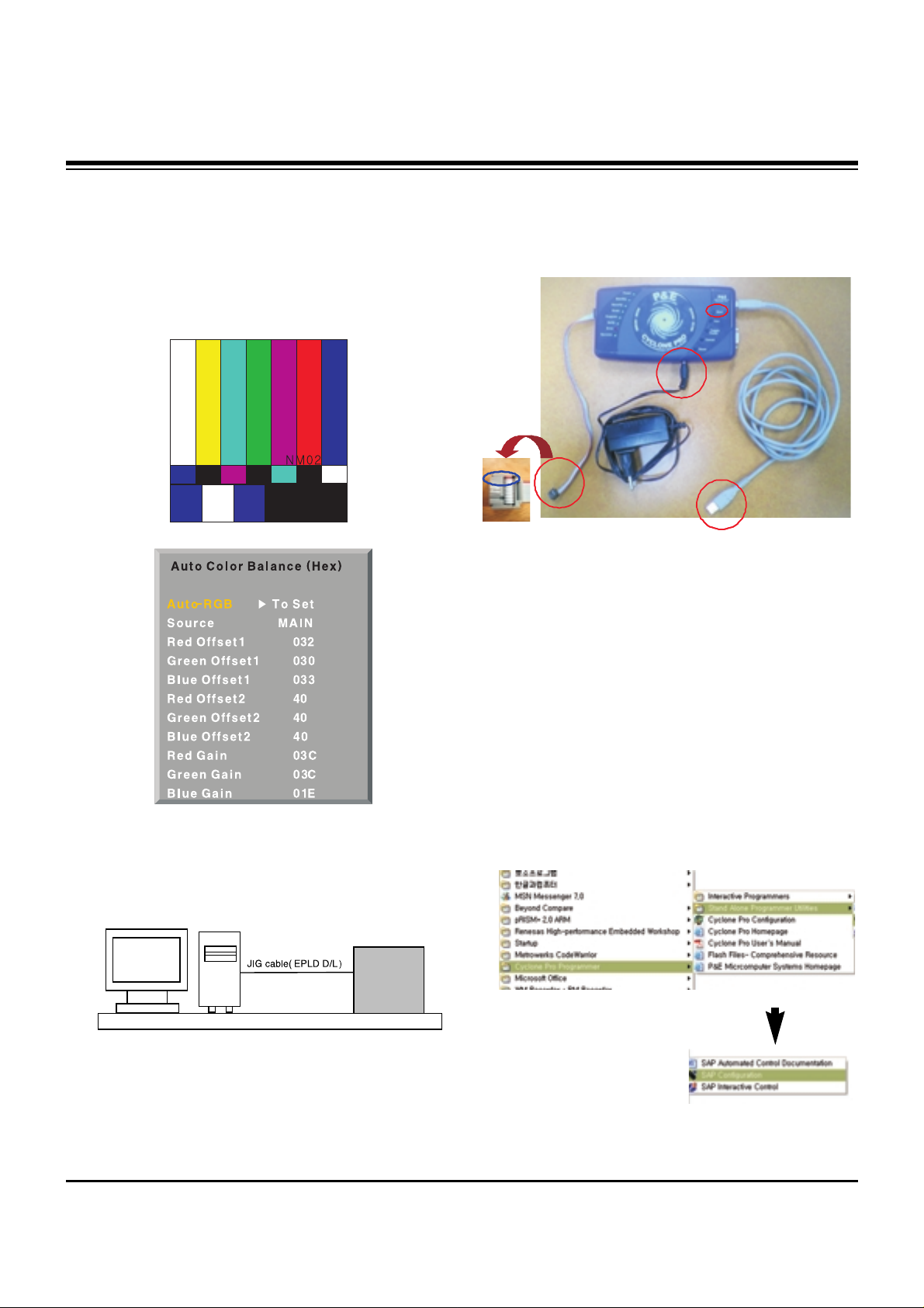
3. Auto AV (CVBS) Color Balance
3-1. Required Equipment
(1) Remote controller for adjustment
(2) AV Pattern Generator: 802F Pattern Generator, Master
(MSPG-925FS), etc
(Which has NTSC-J Composite Video format output with
standard (1.0 Vpp) See Fig. 1)
(3) It is very import to use correct adjustment pattern like
Fig.1.
3-2. Method of Auto AV (CVBS) Color
Balance
(1) Input the NTSC-J Composite Video (Fig.1.) into video
input.
=> MSPG-925FS Model No: 207 / Pattern No: 65 / NTSC-J
(2) Set the EZ Picture to Daylight mode in Video menu.
(3) Press INSTART key on R/C for adjustment.
(4) Press the
G(Vol. +) key operate to set, then it becomes
automatically.
(5) Auto-RGB OK means completed adjustment.
* When adjust main picture, sub picture is included.
ADJUSTMENT INSTRUCTIONS
If you turn on a still screen more than 20 minutes (Especially
Digital pattern(13 CH), Cross Hatch Pattern), an afterimage
may occur in the black level part of the screen.
<Fig. 1> Auto AV (CVBS) Color Balance Test Pattern
Default Value on OSD
Page 7

- 7 -
- 7 -
LGE Internal Use OnlyCopyright©2008 LG Electronics. Inc. All right reserved.
Only for training and service purposes
4. Auto Component Color Balance
4-1. Required Equipment
(1) Remote controller for adjustment
(2) 802F Pattern Generator Which has 720p YPbPr output
with Standard (0.7Vpp) See Fig. 2
(3) It is very important to use correct adjustment pattern like
Fig. 2.
4-2. Method of Auto Component Color
Balance
(1) Input the Component 1280*720p 60Hz signal into
Component.
=> MSPG-925FS Model No: 217 / Pattern No: 65
(2) Set the EZ Pictures to Daylight mode in Video menu.
(3) Press INSTART key on R/C for adjustment.
(4) Press the
G(Vol. +) key operate To set, then it becomes
automatically.
(5) Auto-RGB OK means completed adjustment
5. Auto RGB Color Balance
5-1. Required Equipment
(1) Remote controller for adjustment
(2) 802F Pattern Generator, Master (MSPG-925FS), etc.
(Which has XGA 60Hz PC Format output with standard
(0.7Vpp) See Fig. 3 )
(3) It is very import to use correct adjustment pattern like Fig.
3.
5-2. Method of Auto RGB Color Balance
(1) Input the PC 1024x768 @ 60Hz into RGB.
=> MSPG-925FS Model No: 60 / Pattern No: 65
(2) Set the EZ Pictures to Daylight mode in Video menu.
(3) Press INSTART key on R/C for adjustment.
(4) Press the
G(Vol. +) key operate To set, then it becomes
automatically.
(5) Auto-RGB OK means completed adjustment.
ADJUSTMENT INSTRUCTIONS
<Fig. 2> Auto Component Color Balance Test Pattern
Default Value on OSD
<Fig. 3> Auto RGB Color Balance Test Pattern
Default Value on OSD
Page 8
- 8 -
- 8 -
LGE Internal Use OnlyCopyright©2008 LG Electronics. Inc. All right reserved.
Only for training and service purposes
6. RF Color Balance
(1) Input the RF cable
(2) Set the EZ Pictures to Daylight mode in Video menu.
(3) Press INSTART key on R/C for adjustment.
(4) Press the
G(Vol. +) key operate To set, then it becomes
automatically.
(5) Auto-RGB OK means completed adjustment.
7. EPLD Download
(1) Test Equipment: PC, Jig for download
(2) Connect the power of VSC B/D.
(3) Execute download program(iMPACK) of PC.
(4) After executing the hot key on the Programmer, click icon
(5) End after confirming
8. PTC MICOM Download
8-1. PTC MICOM JIG
(1) Connect power.
(2) Connect the jack(No. 1) to PTC Micom.
(3) Connect the USB Cable(No. 2) and computer.
(4) Execute download program(SAP Configuration)
[ (Caution) PTC Download JIG can save Download file in
memory by Download Program(SAP Configuration).
Because it has a memory chip inside.
After saving the file, you can download it by just pressing
Start button (number 4.).
8-2. Download program(SAP Configuration)
Execute
ADJUSTMENT INSTRUCTIONS
Default Value on OSD
PC
VSC
B/D
Connection Diagram of EPLD Download
Mic om
Micom
Jig
Jig
3.3.
4.Start
4. Start
Mic om
Micom
Jig
Jig
3.3. Power
2. Connect Computer1. Connect Micom port of TV board
4.Start
4. Start Button
<SAP Configuration Process>
(Connect red line (a part of arrow) to port 1)
Page 9
- 9 -
- 9 -
LGE Internal Use OnlyCopyright©2008 LG Electronics. Inc. All right reserved.
Only for training and service purposes
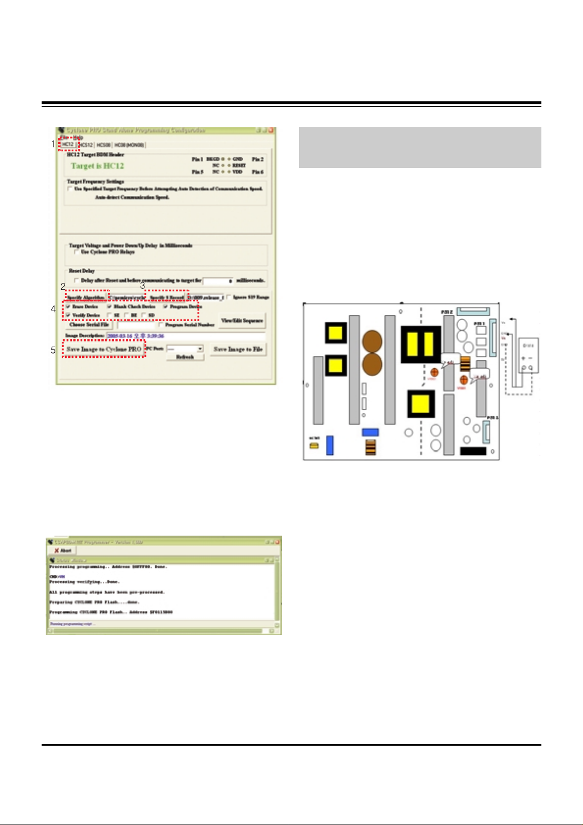
(1) Select HC12.
(2) Specify Algorithm: Select the 9S12dt128_128k.12P file.
(3) Specify S Record: Select the Download file.
(4) Check the check box of Erase Device, Blank Check
Device, Porgram Device, Verify Device.
[ (Caution) Don’t check anywhere except one like picture as
shown.
(5) Press “Save Image to Cyclone PRO” button.
And then the file is downloaded to Download JIG from PC.
(6) When Download is finished, you can download the file by
pressing “start” button on Download JIG.
At first, you download the file, you should not download it
again.
9. POWER PCB Assy Voltage
Adjustment
(Va, Vs Voltage Adjustment)
Caution: Set up “RF mode(noise)” before voltage adjustment.
9-1. Test Equipment :D.M.M 1EA
9-2. Connection Diagram for Measuring
Refer to Fig 4.
9-3. Adjustment
(1) 42” Va Adjustment
1) After receiving 100% Full White Pattern, HEAT RUN.
2) Connect + terminal of D.M.M to Va pin of P811 and
connect – terminal to GND pin of P811.
3) After turning VR901, voltage of D.M.M adjustment as
same as Va voltage which on label of panel Top/Right.
(Deviation : ±0.5V)
(2) 42” Vs Adjustment
1) Connect + terminal of D.M.M to Vs pin of P811 and
connect – terminal to GND pin of P811.
2) After turning VR951, voltage of D.M.M adjustment as
same as Vs voltage which on label of panel Top/Right.
(Deviation : ±0.5V)
ADJUSTMENT INSTRUCTIONS
<Execute SAP Configuration>
<Picture is downloaded to Download JIG>
Each PCB Assy must be checked by Check JIG Set before
assembly. (Especially, be careful Power PCB Assy which can
cause Damage to the PDP Module.)
<Fig. 4> 42 inch Power PCB Assy Voltage Adjustment
Page 10
- 10 -
- 10 -
LGE Internal Use OnlyCopyright©2008 LG Electronics. Inc. All right reserved.
Only for training and service purposes
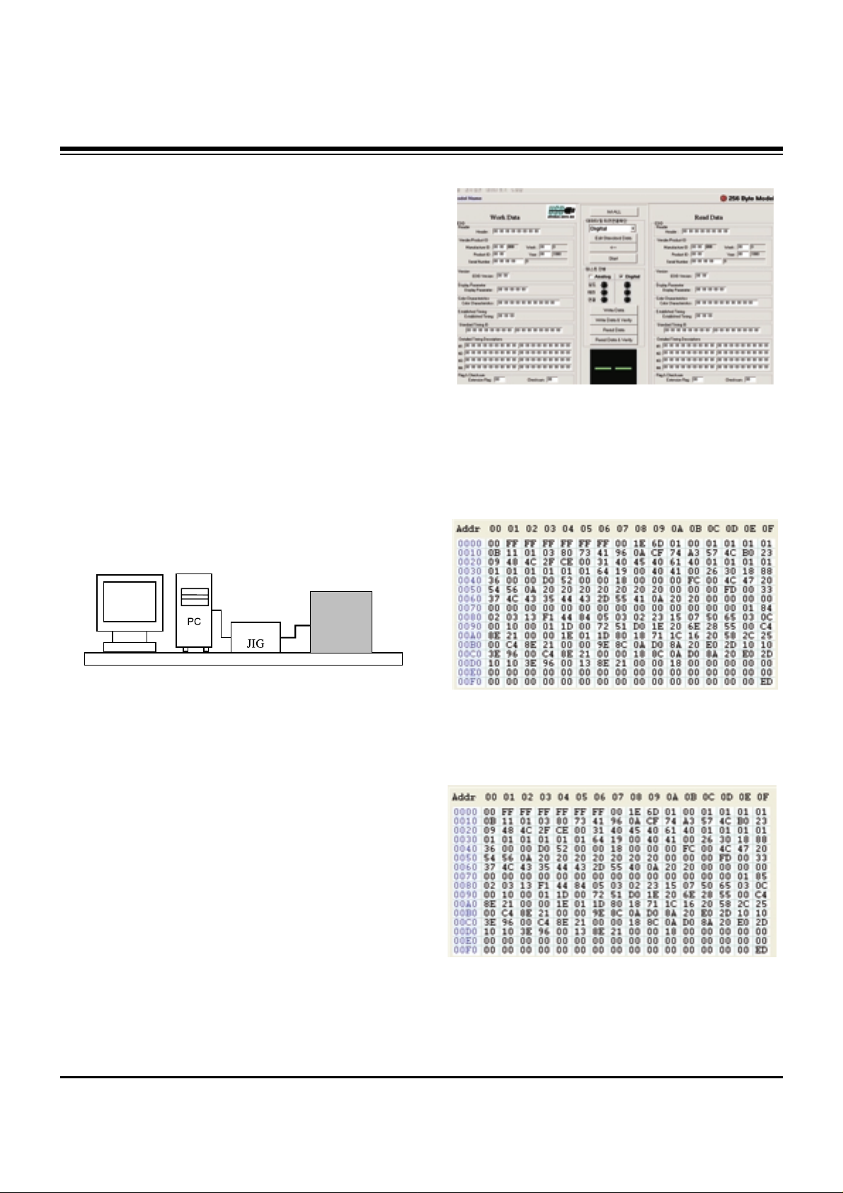
10. EDID(The Extended Display
Identification Data)/DDC
(Display Data Channel) Download
It is the feature to implement the “Plug and Play” which
automatically reconfigures the user’sl environment to directly
use by exchanging information without any command directly
to the PC or the monitor by the user, which is established by
the VESA
10-1. HDMI EDID Data Input
(1) Required Test Equipment
1) PC, Jig for adjusting DDC. (PC serial to D-sub
Connection equipment)
2) S/W for writing DDC(EDID data write & read)
3) D-Sub cable
4) Jig for HDMI Cable connection
(2) Preparation for Adjustments &
Setting of Device
1) Set devices as below and turn on the PC and JIG.
2) Open S/W for writing DDC (EDID data write & read).
(operated in DOS mode)
10-2. Download Method
(1) Set devices as above and turn on the PC and JIG.
(2) Execute DDC Program (EDID data write & read).
(3) Select the EDID data of the said model by selecting Model
-> Open at the menu.
(4) Check the item(s) to download from the <Test processing>
items.
1) HDMI & RGB: Digital & Analog Check
2) (Only)HDMI: Check only the digital
(5) Press ESC (Cancel mode) -> F8 (Auto mode). (Set ‘Auto
Detecting‘)
(6) Connect the said signal cable to the set.
(7) Make sure that the window “Perform the write operation?“
is displayed.
(8) Press the Enter key or the space key to download.
(9) After checking the ’OK’ message after downloading,
disconnect the connected cable.
10-3. EDID DATA for PA64C
:EDID for HDMI 1 (DDC (Display Data Channel) Data)
EDID table =
HDMI1(84ED)
:EDID for HDMI 2 (DDC (Display Data Channel) Data)
EDID table =
HDMI2(85ED)
ADJUSTMENT INSTRUCTIONS
LCD TV SET
(or Digital Board)
<Fig. 5>
Page 11

- 11 -
- 11 -
LGE Internal Use OnlyCopyright©2008 LG Electronics. Inc. All right reserved.
Only for training and service purposes
:EDID for RGB
EDID table(F6) =
11. Adjustment of White Balance
Adjust to equalize the white color caused by the module
deviation
11-1. Required Test Equipment
(1) Color Analyzer: CA-100+(CH 10), CA-100(CH10), CA-
210U(CH 10)
(2) Computer for adjusting (necessary for the automatic
adjustment, possible to communicate with the RS-232C)
(3) Remote controller for adjusting
* Use the instrument with the matrix compensated by the CS-
1000 as the color analyzer.
11-2. Adjustment of White Balance
O
Operate the Zero-calibration of the CA-100, then attach
sensor to PDP module surface when you adjust.
O
Manual adjustment is also possible by the following sequence.
(1) Enter ‘Ez - Adjust’ by pressing ADJ KEY on the Service
Remote Control.
(2) Select "8. WHITE PATTERN" using CH +/- Key and HEAT
RUN at least 30 minutes by pressing the ENTER Key.
(3) Receive the Window pattern signal from Digital Pattern
Generator. (AV Input: connect the ‘HDMI’)
(4) After attaching sensor to center of screen, select ‘5. White-
Balance’ of ‘Ez - Adjust’ by pressing the ADJ KEY on the
Service R/C. Then enter adjustment mode by pressing the
Right KEY (
G
) .
(5) Adjust the Hight Light using R Gain/G Gain/B Gain.(Cool).
Adjust the Hight Light using R Gain/G Gain/B Gain.
(Medium).
Adjust the Hight Light using R Gain/G Gain/B Gain.(Warm).
(6) Adjust using Volume +/- KEY.
(7) After adjustment is complete, exit the adjustment mode by
pressing the ADJ KEY.
High Level: 216gray
[Cool]
X; 0.276±0.002 Y; 0.283±0.002
Color temperature: 11000°K±1000°K
[Medium]
X; 0.285±0.002 Y; 0.293±0.002
Color temperature: 9300°K±1000°K
[Warm]
X; 0.313±0.002 Y; 0.329±0.002
Color temperature: 6500°K±1000°K
ADJUSTMENT INSTRUCTIONS
R Gain
G Gain
B Gain
R offset
G offset
B offset
Jg
Jh
Ji
Cool
Ja
Jb
Jc
Med
RS-232C
COMMAND
CENTER
(DEFAULT)
Jd
Je
Jf
00
00
00
ff
ff
ff
7f
7f
7f
Warm
Min Max
80
75
68
80
74
85
Cool
80
73
6E
80
74
82
Med
80
75
68
80
74
85
Warm
Page 12

- 12 -
- 12 -
LGE Internal Use OnlyCopyright©2008 LG Electronics. Inc. All right reserved.
Only for training and service purposes
12. Commercial Model Test Item
12-1. IR In/Out Check
ADJUSTMENT INSTRUCTIONS
Page 13

- 13 -
- 13 -
LGE Internal Use OnlyCopyright©2008 LG Electronics. Inc. All right reserved.
Only for training and service purposes
12-2. Lodgenet Card & Auto Camport Check
12-3. RJP(Remote Jack Pack) Check
ADJUSTMENT INSTRUCTIONS
Page 14

- 14 -
- 14 -
LGE Internal Use OnlyCopyright©2008 LG Electronics. Inc. All right reserved.
Only for training and service purposes
12-4. MPI Card Check
ADJUSTMENT INSTRUCTIONS
Page 15

- 15 -
- 15 -
LGE Internal Use OnlyCopyright©2008 LG Electronics. Inc. All right reserved.
Only for training and service purposes
BLOCK DIAGRAM
Page 16

- 16 -
- 16 -
LGE Internal Use OnlyCopyright©2008 LG Electronics. Inc. All right reserved.
Only for training and service purposes
BLOCK DIAGRAM
Page 17

- 17 -
- 17 -
LGE Internal Use OnlyCopyright©2008 LG Electronics. Inc. All right reserved.
Only for training and service purposes
BLOCK DIAGRAM
Page 18

- 18 -
- 18 -
LGE Internal Use OnlyCopyright©2008 LG Electronics. Inc. All right reserved.
Only for training and service purposes
BLOCK DIAGRAM
Page 19

- 19 -
- 19 -
LGE Internal Use Only
EXPLODED VIEW
307
120
121
306
560
570
LV1
310
571
302
202
205
590
240
501
250
540
530
580
204
203
303
305
300
304
301
200
206
201
603
602
601
520
270
260
400
A2
Many electrical and mechanical parts in this chassis have special safety-related characteristics. These
parts are identified by in the Schematic Diagram and EXPLODED VIEW.
It is essential that these special safety parts should be replaced with the same components as
recommended in this manual to prevent X-RADIATION, Shock, Fire, or other Hazards.
Do not modify the original design without permission of manufacturer.
IMPORTANT SAFETY NOTICE
Page 20

Copyright©2008 LG Electronics. Inc. All right reserved.
Only for training and service purposes
LGE Internal Use Only
Page 21

Copyright©2008 LG Electronics. Inc. All right reserved.
Only for training and service purposes
LGE Internal Use Only
Page 22

Copyright©2008 LG Electronics. Inc. All right reserved.
Only for training and service purposes
LGE Internal Use Only
Page 23

Copyright©2008 LG Electronics. Inc. All right reserved.
Only for training and service purposes
LGE Internal Use Only
Page 24

Copyright©2008 LG Electronics. Inc. All right reserved.
Only for training and service purposes
LGE Internal Use Only
Page 25

Copyright©2008 LG Electronics. Inc. All right reserved.
Only for training and service purposes
LGE Internal Use Only
Page 26

Copyright©2008 LG Electronics. Inc. All right reserved.
Only for training and service purposes
LGE Internal Use Only
Page 27

Copyright©2008 LG Electronics. Inc. All right reserved.
Only for training and service purposes
LGE Internal Use Only
Page 28

Copyright©2008 LG Electronics. Inc. All right reserved.
Only for training and service purposes
LGE Internal Use Only
Page 29

Copyright©2008 LG Electronics. Inc. All right reserved.
Only for training and service purposes
LGE Internal Use Only
Page 30

Copyright©2008 LG Electronics. Inc. All right reserved.
Only for training and service purposes
LGE Internal Use Only
Page 31

Copyright©2008 LG Electronics. Inc. All right reserved.
Only for training and service purposes
LGE Internal Use Only
Page 32

Copyright©2008 LG Electronics. Inc. All right reserved.
Only for training and service purposes
LGE Internal Use Only
Page 33

Copyright©2008 LG Electronics. Inc. All right reserved.
Only for training and service purposes
LGE Internal Use Only
MAIN(TOP)
Page 34

Copyright©2008 LG Electronics. Inc. All right reserved.
Only for training and service purposes
LGE Internal Use Only
MAIN(BOTTOM)
Page 35

Copyright©2008 LG Electronics. Inc. All right reserved.
Only for training and service purposes
LGE Internal Use Only
CONTROL(TOP) CONTROL(BOTTOM)
PRE AMP(TOP)
PRE AMP(BOTTOM)
VERTICAL(TOP) VERTICAL(BOTTOM)
Page 36

Copyright©2008 LG Electronics. Inc. All right reserved.
Only for training and service purposes
LGE Internal Use Only
MPI(TOP)
MPI(BOTTOM)
Page 37

Sep., 2008
Printed in KoreaP/NO : MFL54063801
CANADA: LG Electronics Canada, Inc. 550 Matheson
Boulevard East Mississauga, Ontario L4Z 4G3
USA : LG Electronics Alabama, Inc.
P.O.Box 240007, 201 James Record Road Bldg 3
Huntsville, AL 35824
 Loading...