


LCD TV
PLASMA TV
OWNER’S MANUAL
LCD TV MODELS
26LC2R
27LC2R
32LC2R
32LC25R
32LC3R
32LX2R
37LE2R
42LE2R
PPlleeaassee rreeaadd
bbeeffoorree rreeaaddiinngg tthhiiss mmaannuuaall aanndd ooppeerraattiinngg yyoouurr sseett..
Retain it for future reference.
Record model number and serial number of the set.
See the label attached on the back cover and quote
this information to your dealer when you require service.
*
*
*
*
*
*
*
*
IInnffoorrmmaattiioonn MMaannuuaall
PLASMA TV MODELS
42PC1RV
42PC3RV
42PC3RA
*
*
*
iinncclluuddeedd ttooggeetthheerr

1-0323E_en_1-rev01 9/29/06 1:45 PM Page 2
Owner's
Manual
OK
INPUT
TVTV
PIP PR-
PIP PR+
PIP INPUT
DVD
ARC
EXIT
VOL
TIME
REVEAL
INDEX
Q.VIEW
PR
SLEEP
LIST
I/II
MENU
PIP SIZE
POSTION
VCR
POWER
123
456
789
*
FAV
?
0
TEXT
INPUT
MUTE
0323A_en_1_rev11 5/25/07 9:46 AM Page 1
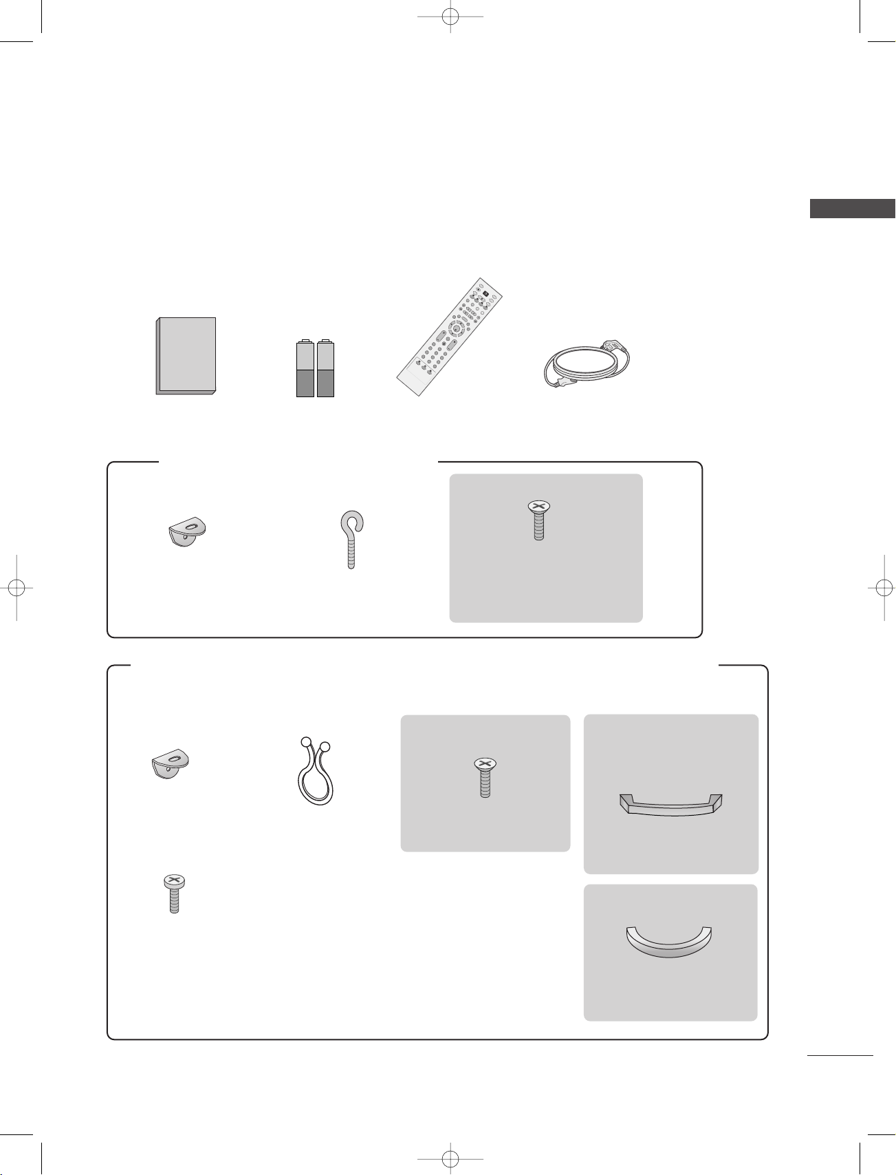
ACCESSORIES
Ensure that the following accessories are included with your TV. If an accessory is missing, please contact the
dealer where you purchased the product.
ACCESSORIES
Owner’s Manual Batteries
FFoo rr 4422PPCC11RRVV**,, 4422PPCC33RRVV**,, 4422PPCC33RRAA
Remote Control Power Cord
**
2-bolts for stand assembly
2-Wall brackets
2-eye-bolts
Refer to p.12
This feature is not available for all
models.
FFoo rr 2266LL CC22RR**,, 2277LL CC22RR**,, 3322LL CC22RR**,, 33 22 LLCC 22 55 RR**,, 2266LL CC33RR**,, 3322LL CC33RR**,, 3322LL XX22RR**,, 3322LL EE22RR**,,
3377LLEE22RR**,, 4422LL EE22RR
**
2266LLCC33RR**,, 3322LL CC22RR**,,
3322LLCC2255RR**,, 3322LL EE22RR
**
2266LLCC22RR**,, 2277LLCC22RR**,, 3322LLCC22RR**,,
3322LLCC2255RR**,, 3322LLEE22RR**,, 3377LLEE22RR**,,
4422LLEE22RR
**
2-TV brackets
2-Wall brackets
Twister Holder
Arrange the wires
with the twister holder.
4-bolts for stand assembly
Management
Cable
2266LLCC33RR**,, 3322LLCC33 RR
**
2-bolts
Cable
Management
1

1-0323E_en_1-rev01 9/29/06 1:45 PM Page 2
CONTENTS
ACCESSORIES . . . . . . . . . . . . . . . . . . . . . . . . . . . . . . . . . . . . . . . . . . .1
CONTENTS
INTRODUCTION
Controls / Connection Options . . . . . . . . . . . . . . . . . . . . . . . . . .
Remote Control Key Functions
Installing Batteries . . . . . . . . . . . . . . . . . . . . . . . . . .12
INSTALLATION
Stand Installation
Basic Connection /
How to Remove the Cable Management
How to join the product assembly to the wall
to protect the set tumbling
CONNECTIONS & SETUP
Antenna Connection
VCR Setup
External Equipment Connections
DVD Setup
STB Setup
PC Setup
Turning the TV On
SPECIAL FUNCTIONS
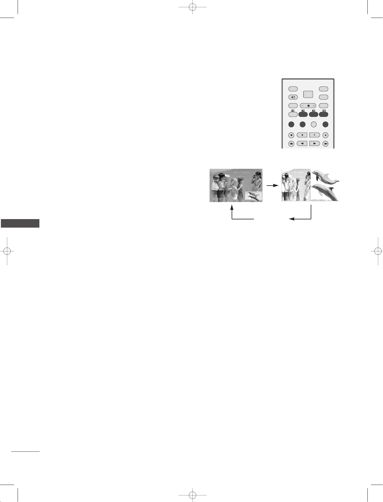
PPIIPP ((PPiiccttuurree--IInn--PPiiccttuurree))
Watching PIP
Programme Selection for Sub Picture
Input Source Selection for Sub Picture
Sub Picture Size Adjustment (PIP mode only) . .32
Moving the Sub Picture (PIP mode only) . . .32
4-9
. . . . . . . . . . . . . . . . . . . . . . . . .11-12
. . . . . . . . . . . . . . . . . . . . . . . . . . . . . . . . . . . . . . . . . . . .13-14
. . . . . . . . . . .15-17
. . . . . . . . . . . . . . . . . . . . . . . . . . . . . . . . . .19
. . . . . . . . . . . . . . . . . . . . . . . . . . . . . . . . . . . . . . . . . . . .20
. . . . . . . . . . . . . . . . . . . . . . . . . . . . . . . . . . . . . . . . . . . . . . . . . . . . .21-22
. . . . . . . . . . . . . . . . . . . . . . . . . .23
. . . . . . . . . . . . . . . . . . . . . . . . . . . . . . . . . . . . . . . . . . . . . . . . . . . . .24-25
. . . . . . . . . . . . . . . . . . . . . . . . . . . . . . . . . . . . . . . . . . . . . . . . . . . . .26-27
. . . . . . . . . . . . . . . . . . . . . . . . . . . . . . . . . . . . . . . . . . . . . . . . . . . . . . .28-29
. . . . . . . . . . . . . . . . . . . . . . . . . . . . . . . . . . . . . . . . .30-31
. . . . . . . . . . . . . . . . . . . . . . . . . . . . . . . . . . . . . . . . . . . . . . .32
. . . . . . . . . . . .32
. . . . . . . . . .32
TV MENU
On Screen Menus Selection and Adjustment . . . . .36
SSeettttiinngg uupp TTVV ssttaattiioonnss
Auto programme tuning
Manual programme tuning
Fine tuning
. . . . . . . . . . . . . . . . . . . . . . . . . . . . . . . . . . . . . . . . . . . . . . . . . .39
Assigning a station name
Programme edit
. . . . . . . . . . . . . . . . . . . . . . . . . . . . . . . . . . . . . . . . . . . .41
Favourite programme
Calling the programme table
. . . . . . . . . . . . . . . . . . . . . . . . . . . . . . .
. . . . . . . . . . . . . . . . . . . . . . . . . . . .
. . . . . . . . . . . . . . . . . . . . . . . . . . . . . . .40
. . . . . . . . . . . . . . . . . . . . . . . . . . . . . . . . . . . .
. . . . . . . . . . . . . . . . . . . . . . . . .
PPiiccttuurree MMeennuu OOppttiioonnss
PSM (Picture Status Memory)
. . . . . . . . . . . . . . . . . . . . . .44
Picture Adjustment (PSM-User option)
CSM (Colour Status Memory)
. . . . . . . . . . . . . . . . . . . . . .46
Manual Colour Temperature Control
(CSM - User option)
Function
ADVANCED-CINEMA
ADVANCED-BLACK LEVEL
. . . . . . . . . . . . . . . . . . . . . . . . . . . . . . . . . . . .47
. . . . . . . . . . . . . . . . . . . . . . . . . . . . . . . . . . . . . . . . . . .48
. . . . . . . . . . . . . . . . . . . . . . . . . . . . . . . . . . .49
. . . . . . . . . . . . . . . . . . . . . . . . . . . .
Reset . . . . . . . . . . . . . . . . . . . . . . . . . . . . . . . . . . . . . . . . . . . . . . . . . . . . . . . . . . .51
SSoouunndd MMeennuu OOppttiioonnss
SSM (Sound Status Memory)
. . . . . . . . . . . . . . . . . . . . . . .52
Sound Frequency Adjustment
(SSM - User option)
AVL (Auto Volume Leveler)
Balance Adjustment
Speaker
. . . . . . . . . . . . . . . . . . . . . . . . . . . . . . . . . . . . . . . . . . . . . . . . . . . . . . .56
Stereo/Dual Reception
NICAM Reception
Speaker Sound Output Selection
. . . . . . . . . . . . . . . . . . . . . . . . . . . . . . . . . . . .53
. . . . . . . . . . . . . . . . . . . . . . . . . . .54
. . . . . . . . . . . . . . . . . . . . . . . . . . . . . . . . . . . . .55
. . . . . . . . . . . . . . . . . . . . . . . . . . . . . . . . .57
. . . . . . . . . . . . . . . . . . . . . . . . . . . . . . . . . . . . . . . .58
. . . . . . . . . . . . . . . . . .58
TTiimmee MMeennuu OOppttiioonnss
37
38
42
43
. . . . . . . . .45
50
2
TTee lleetteexxtt
Switch on/off . . . . . . . . . . . . . . . . . . . . . . . . .33
SIMPLE Text . . . . . . . . . . . . . . . . . . . . . . . . . .33
TOP Text . . . . . . . . . . . . . . . . . . . . . . . . . . . . .34
FASTEXT . . . . . . . . . . . . . . . . . . . . . . . . . . . . .34
Special Teletext Functions . . . . . . . . . . . . . . .35
Clock Setup . . . . . . . . . . . . . . . . . . . . . . . . . . . . . . . . . . . . . . . . . . . . . . . . .59
On/Off Time
Auto Sleep
Sleep Timer
. . . . . . . . . . . . . . . . . . . . . . . . . . . . . . . . . . . . . . . . . . . . . . .60
. . . . . . . . . . . . . . . . . . . . . . . . . . . . . . . . . . . . . . . . . . . . . . . . . . .61
. . . . . . . . . . . . . . . . . . . . . . . . . . . . . . . . . . . . . . . . . . . . . . . . .61
SSppeecciiaall MMeennuu OOppttiioonnss
Child Lock
ISM (Image Sticking Minimization) Method
Low Power
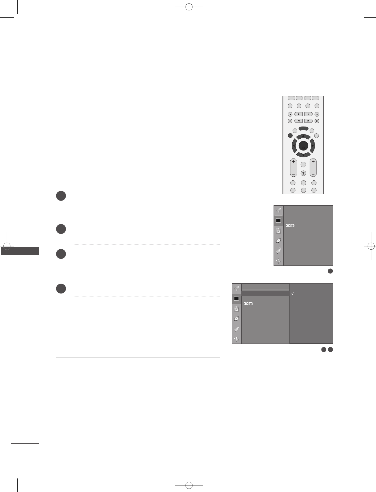
XD Demo
. . . . . . . . . . . . . . . . . . . . . . . . . . . . . . . . . . . . . . . . . . . . . . . . . . .62
. . .63
. . . . . . . . . . . . . . . . . . . . . . . . . . . . . . . . . . . . . . . . . . . . . . . . . . .64
. . . . . . . . . . . . . . . . . . . . . . . . . . . . . . . . . . . . . . . . . . . . . . . . . . . .65

1-0323E_en_1-rev01 9/29/06 1:45 PM Page 3
TV MENU
SSccrreeeenn MMeennuu OOppttiioonnss
Auto Configure (RGB [PC] mode only)
. . . . . . . . . . . .66
Manual Configure . . . . . . . . . . . . . . . . . . . . . . . . . . . . . . . . . . . . . . . .67
Setting the Picture Format . . . . . . . . . . . . . . . . . . . . . .68-69
Selecting Wide VGA/XGA mode . . . . . . . . . . . . . . . . . . .69
Initializing
(Reset to original factory settings) . . . . . . . . . . . . . . . .70
APPENDIX
Programming the Remote
Programming code
Troubleshooting Checklist
Maintenance
. . . . . . . . . . . . . . . . . . . . . . . . . . . . . . . . . . . . . . . . . . . . . . . . . .
Product Specifications
External Control Device Setup
IR Codes
. . . . . . . . . . . . . . . . . . . . . . . . . . . . . . . . . . . . . . . . . . . . . . . . . . . . . . .
Remote control ir codes
. . . . . . . . . . . . . . . . . . . . . . . . . . . . . . . . . .
. . . . . . . . . . . . . . . . . . . . . . . . . . . . . . . . . . . . .
. . . . . . . . . . . . . . . . . . . . . . . . . . . .
. . . . . . . . . . . . . . . . . . . . . . . . . . . . . . . .
. . . . . . . . . . . . . . . . . . . . . . . . . . .
. . . . . . . . . . . . . . . . . . . . . . . . . . . . . . . . . . .
71
71-72
73-74
75
76-77
78
85
86
CONTENTS
3
PR
VOL
OKOK
MENU
INPUT
PR
VOL
OK
MENU
INPUT
1-0323E_en_1-rev01 9/29/06 1:45 PM Page 4
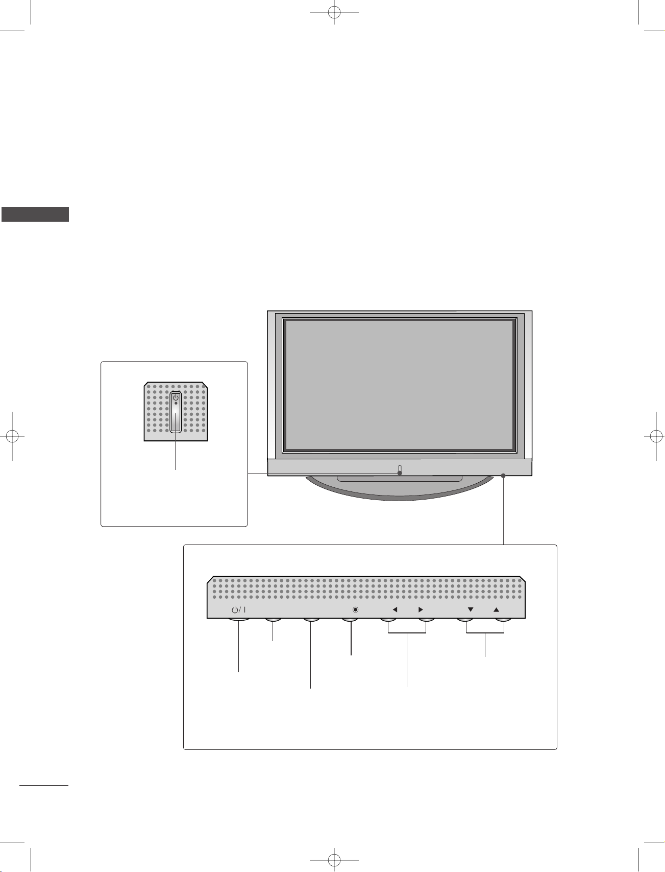
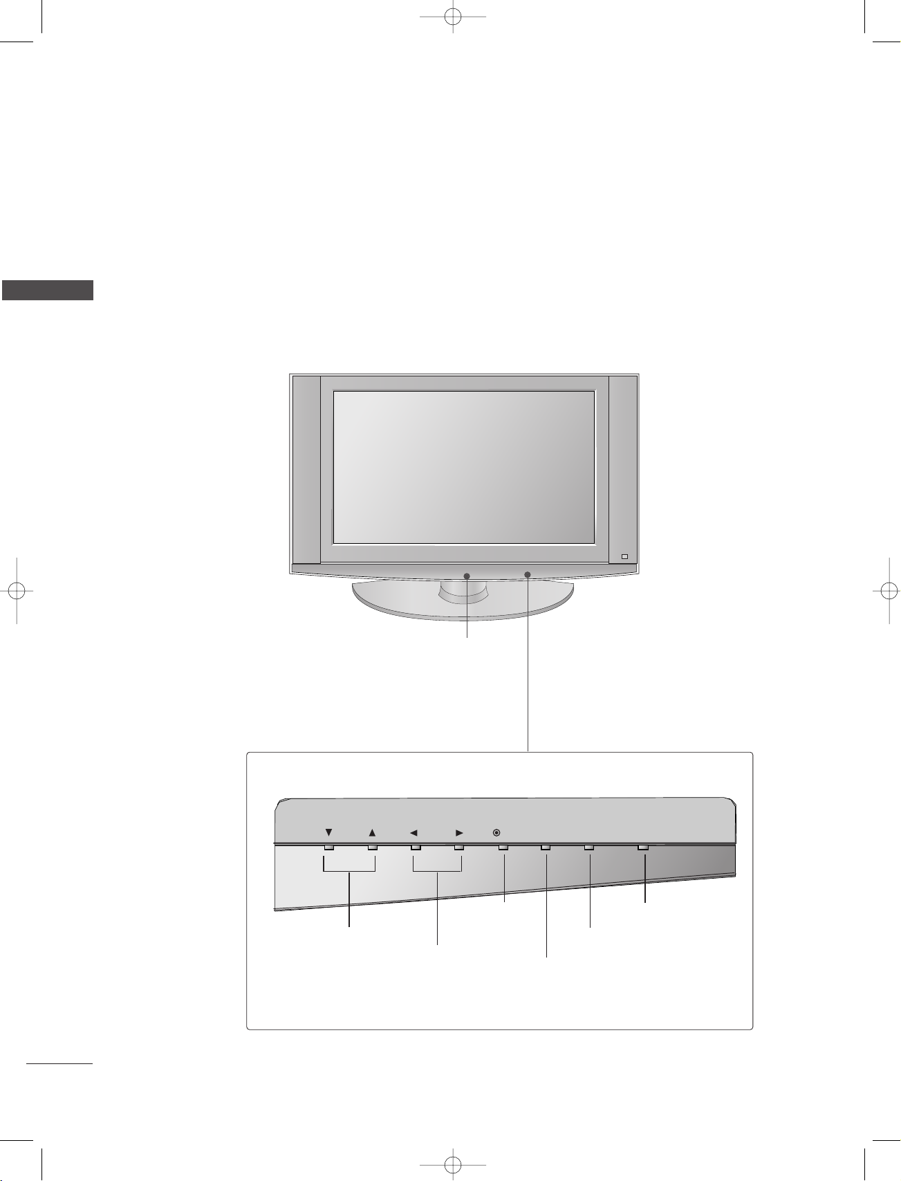
INTRODUCTION
CONTROLS
This is the front panel of models 42PC1RV*TVs.
■
This is a simplified representation of the front panel. Here shown may be somewhat different from your TV.
INTRODUCTION
Front Panel Controls
Power/Standby Indicator
• illuminates red in standby mode.
• illuminates white when the set is
switched on.
POWER Button
INPUT Button
OK Button
MENU Button
PROGRAMME Buttons
VOLUME Buttons
4
PR
VOL
OK
MENU
INPUT
1-0323E_en_1-rev01 9/29/06 1:45 PM Page 5
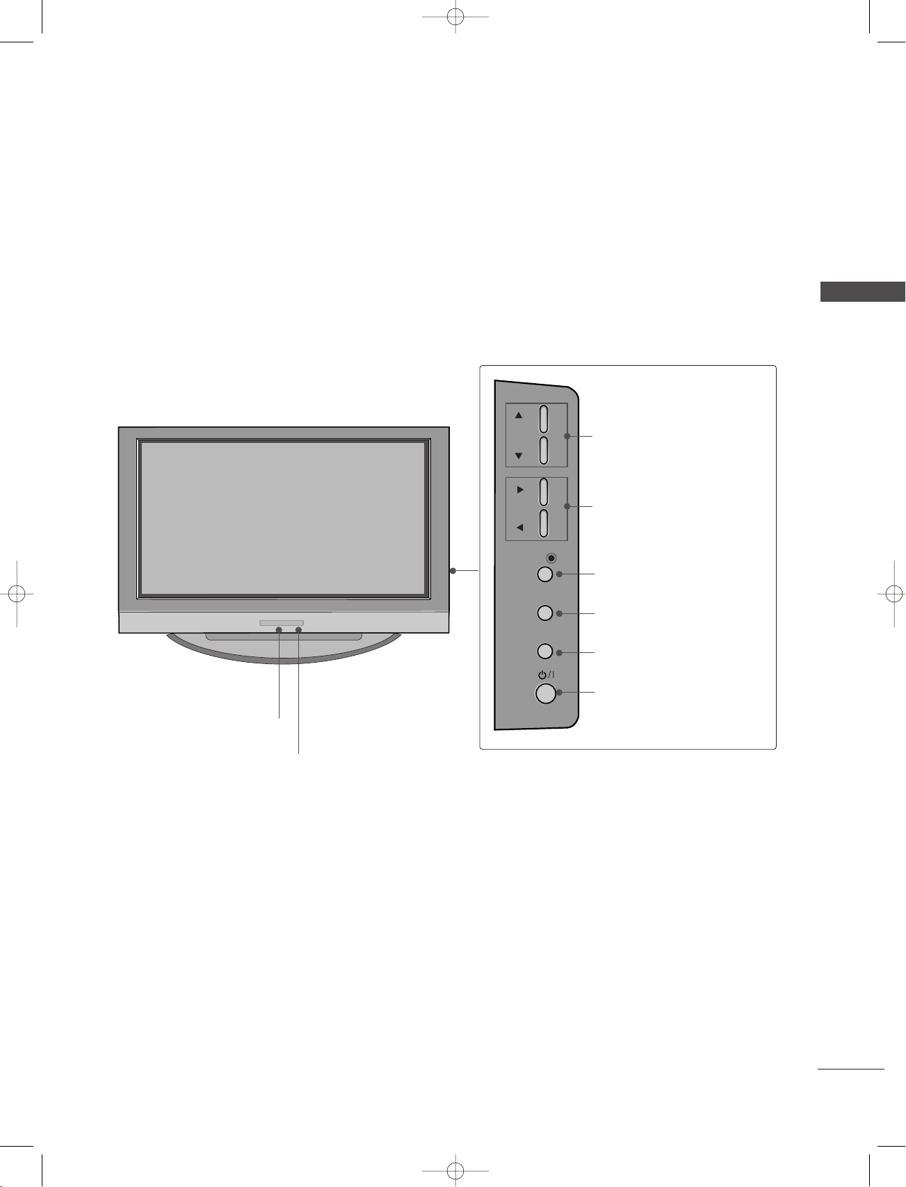
This is the front panel of models 42PC3RV*, 42PC3RA*TVs.
■
This is a simplified representation of the front panel. Here shown may be somewhat different from your TV.
Front Panel Controls
INTRODUCTION
Remote Control Sensor
Power/Standby Indicator
• illuminates red in standby mode.
• illuminates white when the set is switched on.
PROGRAMME Buttons
VOLUME Buttons
OK Button
MENU Button
INPUT Button
ON/OFF Button
5
REMOTE
CONTROL IN
AUDIO IN
(RGB)
AC IN
AV 1 AV 2
MONO
( )
AUDIOUDIO
RGB IN
(PC/DTV)
RS-232C INRS-232C IN
(CONTROL & SERVICE)
HDMI IN
ANTENNA
IN
VIDEOVIDEO
S-VIDEOS-VIDEO
AV IN 3
AUDIO OUT
VARIABLE
VIDEOVIDEO
AUDIOUDIO
COMPONENT INCOMPONENT IN
AV IN 4
L/MONO
R
AUDIOAUDIO
VIDEOVIDEO
1-0323E_en_1-rev01 9/29/06 1:45 PM Page 6
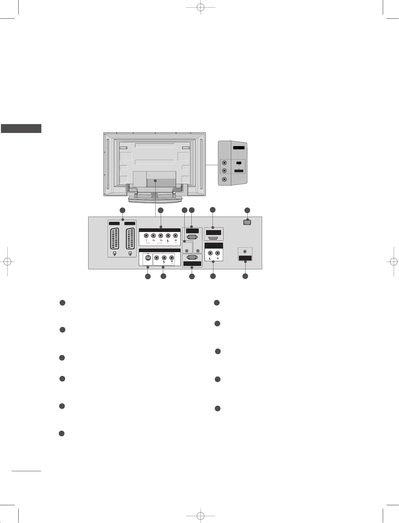
INTRODUCTION
CONNECTION OPTION
This is the back panel of models 42PC1RV*, 42PC3RV*, 42PC3RA*TVs.
Back Connection Panel
INTRODUCTION
1
Euro Scart Socket (AV1/AV2)
Connect scart socket input or output from an
external device to these jacks.
2
Component Input
Connect a component video/audio device to
these jacks.
3
Remote Control Port
Connect your wired remote control here.
4
RGB/Audio Input
Connect the monitor output from a PC to the
appropriate input port.
5
HDMI Input
Connect a HDMI signal to HDMI port with HDMI
cable.
7
21
42PC1RV*only
AUDIO Input
Connections are available for listening
stereo sound from an external device.
VIDEO Input
Connects the video signal from a video
device.
4
3
8
9
5
10 11
7
S-Video Input
6
Connect S-Video out from an S-VIDEO device.
8
Audio/Video Input
Connect audio/video output from an external
device to these jacks.
9
RS-232C Input
(CONTROL&SERVICE) Port
Connect the serial port of the control devices to
the RS-232C jack.
10
Variable Audio Output
Connect an external amplifier or add a subwoofer
to your surround sound system.
11
Antenna Input
Connect over-the-air signals to this jack.
6
6
Power Cord Socket
This TV operates on an AC power. The voltage is
indicated on the Specifications page. Never
attempt to operate the TV on DC power.

R
R
PR
VOL
OK
MENU
INPUT
/I
1-0323E_en_1-rev01 9/29/06 1:45 PM Page 7
This is the front panel of models 26LC2R*, 26LC3R*, 27LC2R*, 32LC2R*, 32LC25R*, 32LC3R*, 32LE2R*,
37LE2R*, 42LE2R*TVs.
■
This is a simplified representation of the front panel. Here shown may be somewhat different from your TV.
Front Panel Controls
26LC2R*, 27LC2R*, 32LC2R*, 32LC25R*, 32LE2R*,
37LE2R*, 42LE2R
Remote Control Sensor
Power/Standby Indicator
• illuminates red in standby mode.
• illuminates white when the set is switched on.
26LC3R*, 32LC3R
*
*
INTRODUCTION
PROGRAMME Buttons
VOLUME Buttons
OK Button
MENU Button
INPUT Button
Remote Control Sensor
Power/Standby Indicator
• illuminates red in standby mode.
• illuminates white when the set is switched on.
ON/OFF Button
7
1-0323E_en_1-rev01 9/29/06 1:45 PM Page 8
INTRODUCTION
CONNECTION OPTION
This is the front panel of models 32LX2R*TV.
■
This is a simplified representation of the front panel. Here shown may be somewhat different from your TV.
INTRODUCTION
Front Panel Controls
Remote Control Sensor
Power/Standby Indicator
• illuminates red in standby mode.
• illuminates white when the set is switched on.
8
PR
PROGRAMME Buttons
VOL
OK Button
VOLUME Buttons
MENU
OK INPUT
INPUT Button
MENU Button
ON/OFF
POWER Button
REMOTE
CONTROL IN
AUDIO IN
(RGB)
AC IN
AV 1 AV 2
MONO
( )
AUDIOUDIO
RGB IN
(PC/DTV)
RS-232C INRS-232C IN
(CONTROL & SERVICE)
HDM IN
ANTENNA
IN
VIDEOVIDEO
S-VIDEOS-VIDEO
AV IN 3
AUDIO OUT
VARIABLE
VIDEOVIDEO
AUDIOUDIO
COMPONENT INCOMPONENT IN
AV IN 4
AUDIOAUDIOVIDEOVIDEO
L/MONO
R
AC IN
AV IN 4
AUDIOAUDIOVIDEOVIDEO
L/MONO
R
1-0323E_en_1-rev01 9/29/06 1:45 PM Page 9
CONTROLS
This is the back panel of models 26LC2R*, 26LC3R*, 27LC2R*TVs.
Back Connection Panel
31 2
8
7
1
Power Cord Socket
This TV operates on an AC power. The voltage is
indicated on the Specifications page. Never
attempt to operate the TV on DC power.
2
Euro Scart Socket (AV1/AV2)
Connect scart socket input or output from an
external device to these jacks.
3
Component Input
Connect a component video/audio device to
these jacks.
4
Remote Control Port
Connect your wired remote control here.
5
RGB/Audio Input
Connect the monitor output from a PC to the
appropriate input port.
26LC2R
27LC2R
*
*
26LC3R
*
INTRODUCTION
AUDIO Input
Connections are available for listening
stereo sound from an external device.
VIDEO Input
Connects the video signal from a video
device.
5
4
9
6
10 11
7
S-Video Input
Connect S-Video out from an S-VIDEO device.
8
Audio/Video Input
Connect audio/video output from an external
device to these jacks.
9
RS-232C Input
(CONTROL&SERVICE) Port
Connect the serial port of the control devices to
the RS-232C jack.
10
Variable Audio Output
Connect an external amplifier or add a subwoofer
to your surround sound system.
11
Antenna Input
Connect over-the-air signals to this jack.
6
HDMI Input
Connect a HDMI signal to HDMI port with HDMI
cable.
9
REMOTE
CONTROL IN
AUDIO IN
(RGB)
AC IN
AV 1 AV 2V 2
MONO
( )
AUDIOUDIO
RGB IN
(PC/DTV)
RS-232C INRS-232C IN
(CONTROL & SERVICE)
HDM IN
ANTENNA
IN
VIDEOVIDEO
S-VIDEOS-VIDEO
AV IN 3
AUDIO OUT
VARIABLE
VIDEOVIDEO
AUDIOUDIO
COMPONENT INCOMPONENT IN
AC IN
AV IN 4
L/MONO
R
AUDIOAUDIO
VIDEOVIDEO
AV IN 4
L/MONOMONO
R
AUDIOAUDIO
VIDEOVIDEO
AV IN 4
AUDIOAUDIOVIDEOVIDEO
L/MONO
R
1-0323E_en_1-rev01 9/29/06 1:45 PM Page 10
INTRODUCTION
CONTROLS
This is the back panel of models 32LC2R*, 32LC25R*, 32LC3R*, 32LX2R*, 32LE2R*, 37LE2R*, 42LE2R*TVs.
Back Connection Panel
INTRODUCTION
32LC2R
32LC25R
32LX2R
32LE2R
5
31 2
4
6
*
*
*
*
32LC3R
*
37LE2R
42LE2R
*
*
AUDIO Input
Connections are available for listening
stereo sound from an external device.
VIDEO Input
Connects the video signal from the video
device.
8
7
9
10 11
10
1
Power Cord Socket
This TV operates on an AC power. The voltage is
indicated on the Specifications page. Never
attempt to operate the TV on DC power.
2
Euro Scart Socket (AV1/AV2)
Connect scart socket input or output from an
external device to these jacks.
3
Component Input
Connect a component video/audio device to
these jacks.
4
Remote Control Port
Connect your wired remote control here.
5
RGB/Audio Input
Connect the monitor output from a PC to the
appropriate input port.
6
HDMI Input
Connect a HDMI signal to HDMI port with HDMI
cable.
7
S-Video Input
Connect S-Video out from an S-VIDEO device.
8
Audio/Video Input
Connect audio/video output from an external
device to these jacks.
9
RS-232C Input
(CONTROL&SERVICE) Port
Connect the serial port of the control devices to
the RS-232C jack.
10
Variable Audio Output
Connect an external amplifier or add a subwoofer
to your surround sound system.
11
Antenna Input
Connect over-the-air signals to this jack.
OK
INPUT
TVTV
PIP PR- PIP PR+
PIP INPUT
DVD
ARC
EXIT
VOL
TIME
REVEAL
INDEX
Q.VIEW
PR
SLEEP
LIST
I/II
MENU
PIP SIZE
POSTION
VCR
POWER
123
456
789
*
0
FAV
?
TEXT
INPUT
MUTE
1-0323E_en_1-rev01 9/29/06 1:45 PM Page 11
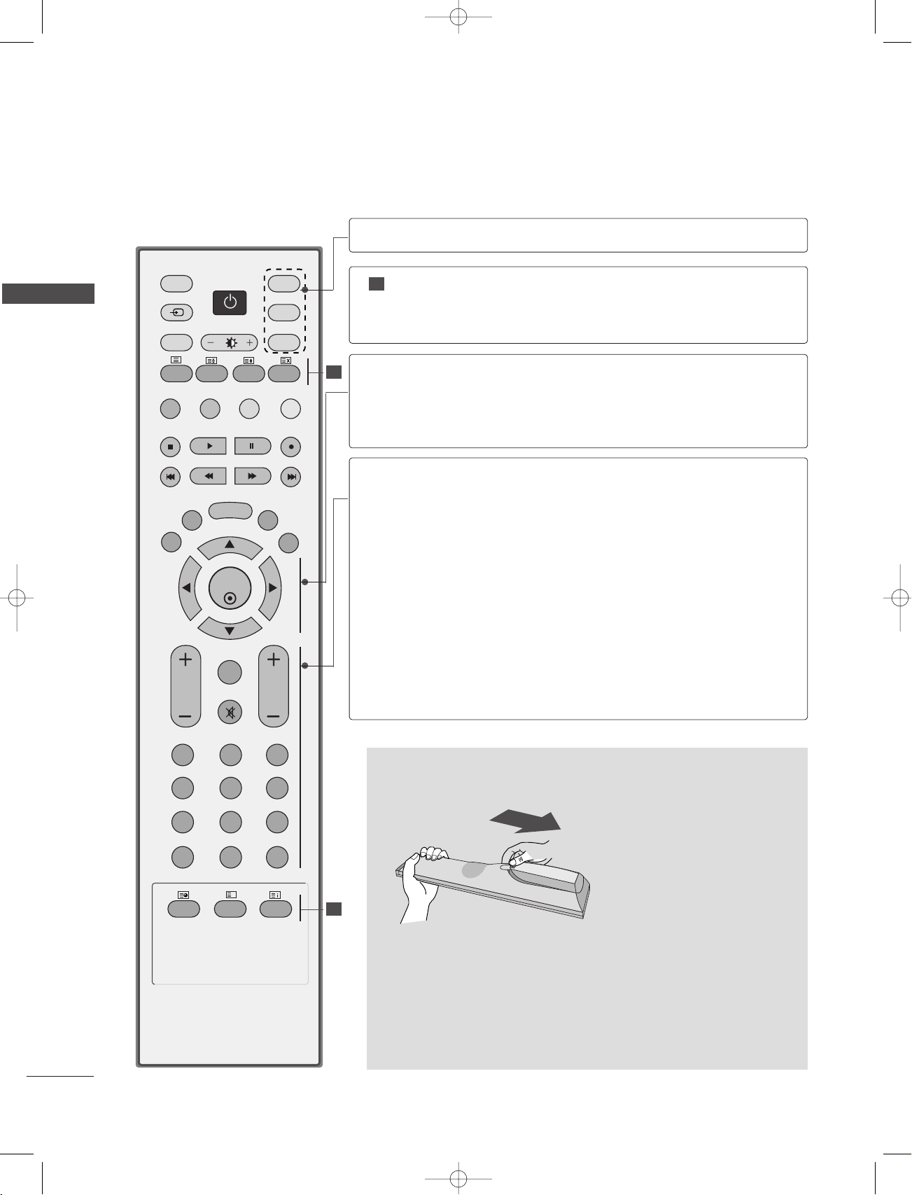
REMOTE CONTROL KEY FUNCTIONS
When using the remote control, aim it at the remote control sensor on the TV.
POWER
TV INPUT
INPUT
ARC
Brightness
adjustment
PIP
SIZE
POSITION
Switches the set on from standby or off to standby.
Returns to the TV viewing from any mode.
Switches the set on from standby.
If you press the button once, the input source OSD
will appear on screen as shown. Press the
DD/ EE
button and then OK button to select the desired input
source (TV, AV1 , AV2, S-Video2 , AV3 , AV4 (except
42PC3RV*, 42PC3RA*), Component , RGB, or HDMI).
Selects your desired picture format.
Adjusts screen brightness.
It returns to the default settings brightness by changing
mode source.
Switches the sub picture PIP, DW mode.
Adjusts the sub picture size.
Moves the sub picture.
INTRODUCTION
PIP PR - /+
PIP INPUT
Coloured
buttons
VCR/DVD
control buttons
EXIT
LIST
MENU
I/II
SLEEP
Selects a programme for the sub picture.
Selects the input source for the sub picture in PIP/Twin
picture mode.
These buttons are used for teletext (only
models) or
PPrrooggrraammmmee eeddiitt
.
TTEELLEETTEEXXTT
Controls some video cassette recorders or DVD players
when you have already selected DVD or VCR mode button.
Clears all on-screen displays and returns to TV viewing
from any menu.
Displays the programme table.
Selects a menu.
Selects the sound output.
Sets the sleep timer.
11
OK
INPUT
TVTV
PIP PR- PIP PR+
PIP INPUT
DVD
ARC
EXIT
VOL
TIME
REVEAL
INDEX
Q.VIEW
PR
SLEEP
LIST
I/II
MENU
TEXT PIP SIZE
POSTION
VCR
POWER
123
456
789
*
FAV
?
0
INPUT
MUTE
1-0323E_en_1-rev01 9/29/06 1:45 PM Page 12
INTRODUCTION
INTRODUCTION
1
THUMBSTICK
(Up/Down/Left
MODE
1
TELETEXT
BUTTONS
Right)
OK
VOLUME UP
/DOWN
Q.VIEW
MUTE
Programme
UP/DOWN
0~9 number
button
Selects the remote operating modes.
These buttons are used for teletext.
For further details, see the ‘Teletext’ section.
Allows you to navigate the on-screen menus and adjust
the system settings to your preference.
Accepts your selection or displays the current mode.
Adjusts the volume.
Returns to the previously viewed programme.
Switches the sound on or off.
Selects a programme.
Selects a programme.
Selects numbered items in a menu.
Displays the selected favourite programme.
FAV
No function
*
INSTALLING BATTERIES
1
■
Open the battery compartment cover on the back side and install
the batteries matching correct polarity (+ with +, - with -).
■
Install two 1.5V AA batteries. Don’t mix old or used batteries with
new ones.
■
Close cover.
12
!
1-0323E_en_1-rev01 9/29/06 1:45 PM Page 13
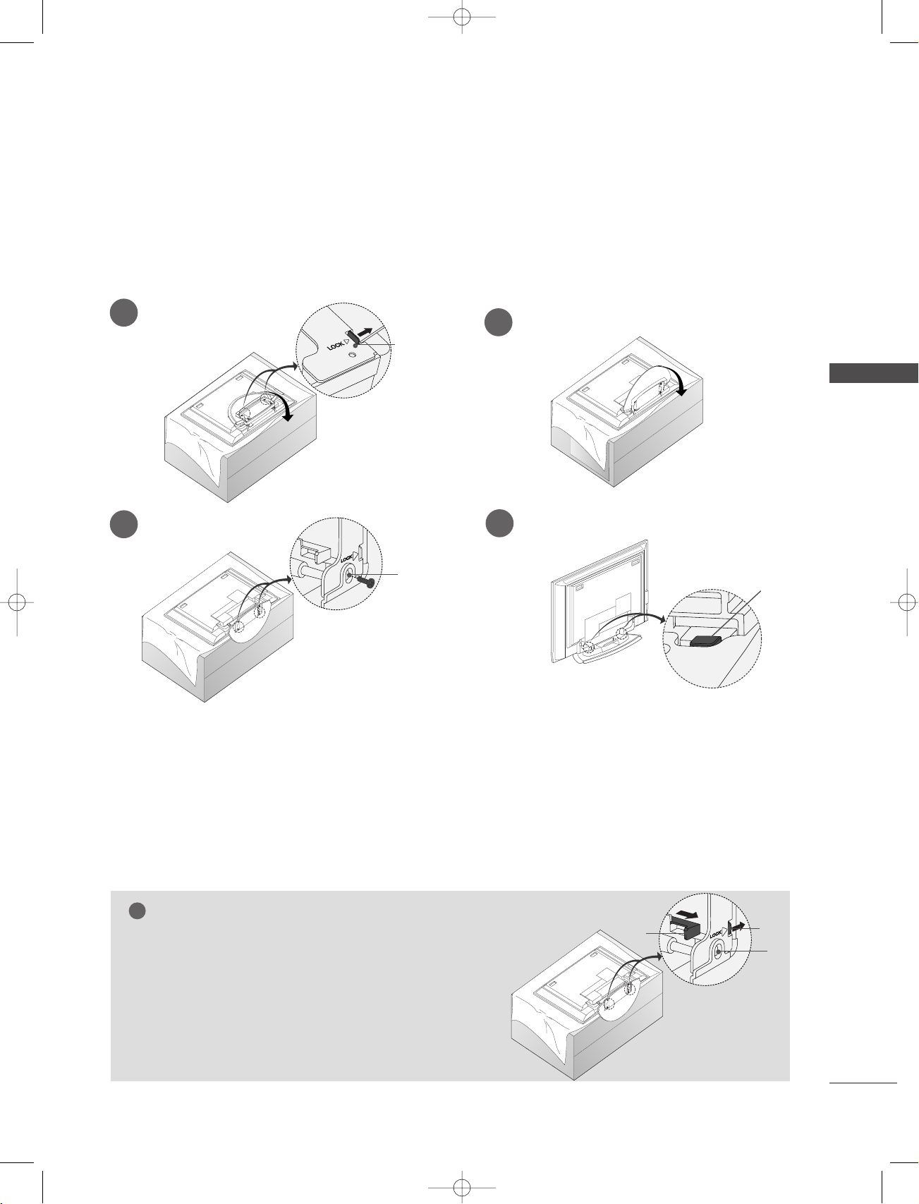
INSTALLATION
STAND INSTALLATION
■
This feature is not available for all models.
1
3
2
A
INSTALLATION
4
B
C
■
Place the set with the screen facing down on a cushion or soft cloth as shown in Figures 1.
Before unfolding the stand,please make sure two locks (A)on the bottom of the stand push outward.
■
Pull the stand out as shown above in Figures 2 ~ 3.
After unfolding the stand,please insert and tighten the screws in the holes (B)on the bottom of the stand.
■
When connecting cables to the set,Do not disengage the lock (C).
This may cause the set to fall,causing serious bodily injury and serious damage to the set.
NOTE
Figures shown here may be slightly different from your set.
WWhheenn cclloossiinngg tthhee ssttaanndd ffoorr ssttoorraaggee
First remove the screws in the holes (B)on the bottom of the
stand.And then pull two Hooks (D)of the stand bottom and
fold the stand into the back of the set.
After folding,push two Locks (A)of the stand bottom outward.
D
A
B
13
0323A_en_1_rev11 5/23/07 11:49 AM Page 14
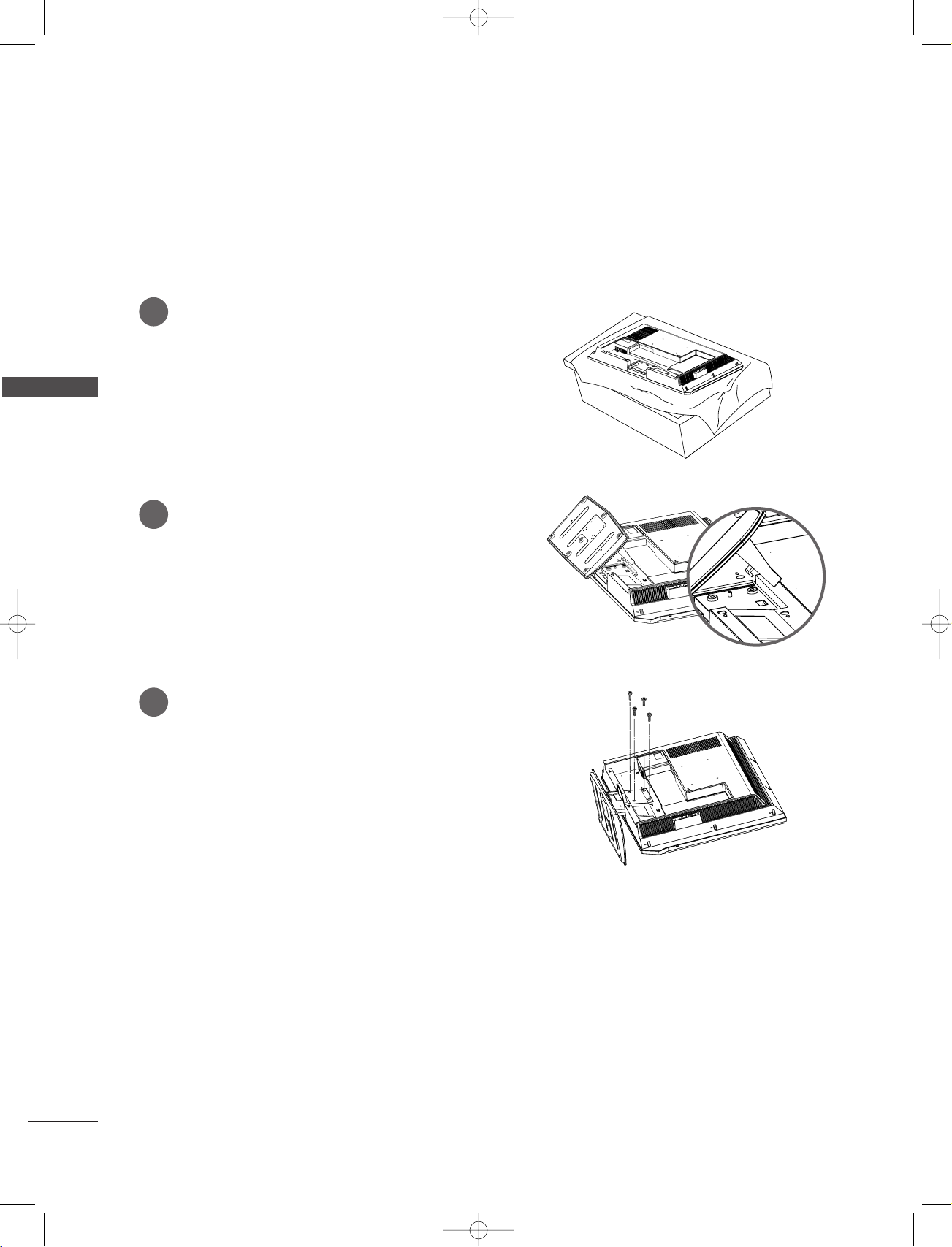
INSTALLATION
STAND INSTALLATION
(Only 26LC3R*, 32LC2R*, 32LC25R*, 32LE2R*)
Carefully place the product screen side down on
1
a cushioned surface that will protect product
and screen from damage.
INSTALLATION
Place the product stand on the product as
2
shown.
Install the 4 bolts securely, in the back of the
3
product in the holes provided.
14
1-0323E_en_1-rev01 9/29/06 1:45 PM Page 15
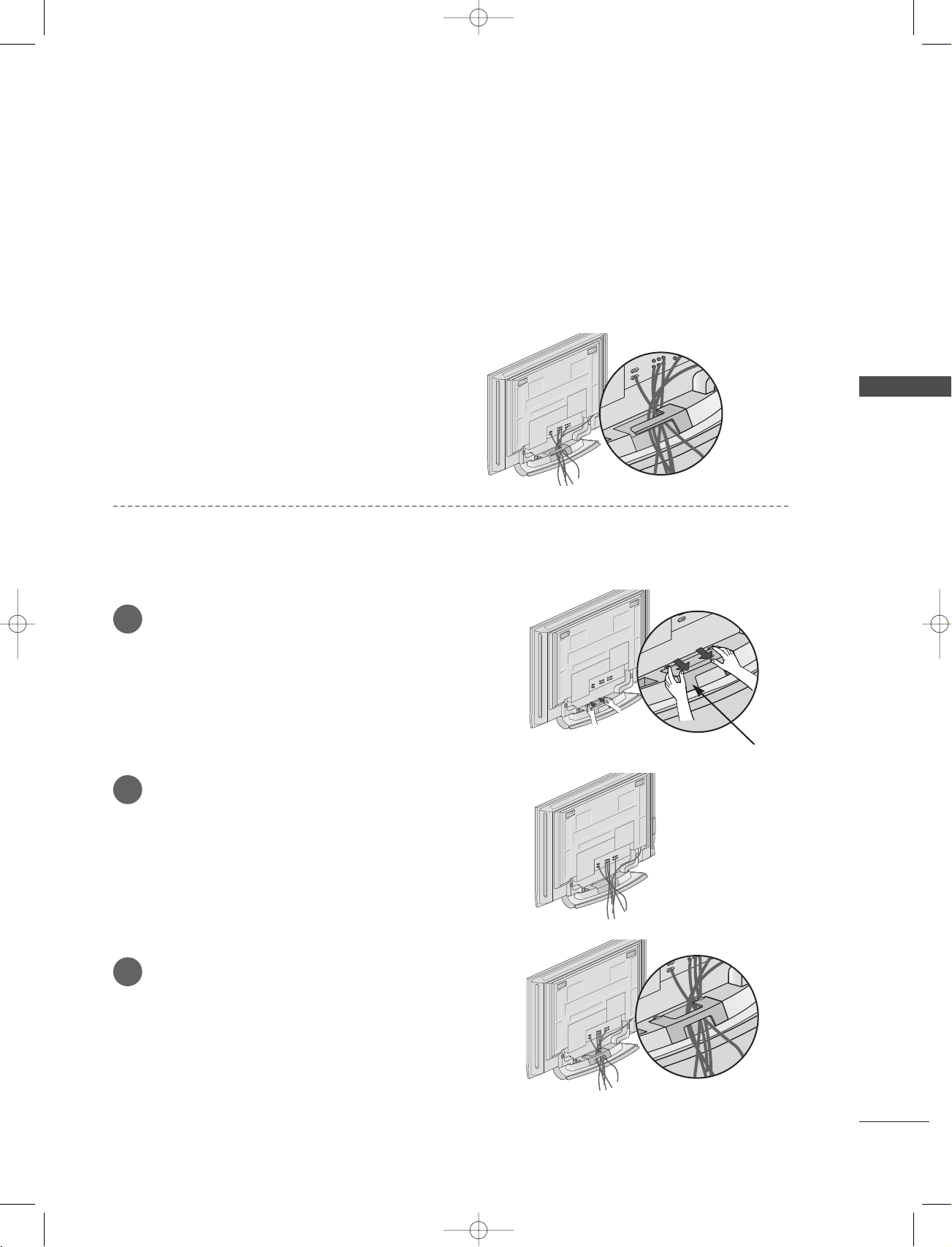
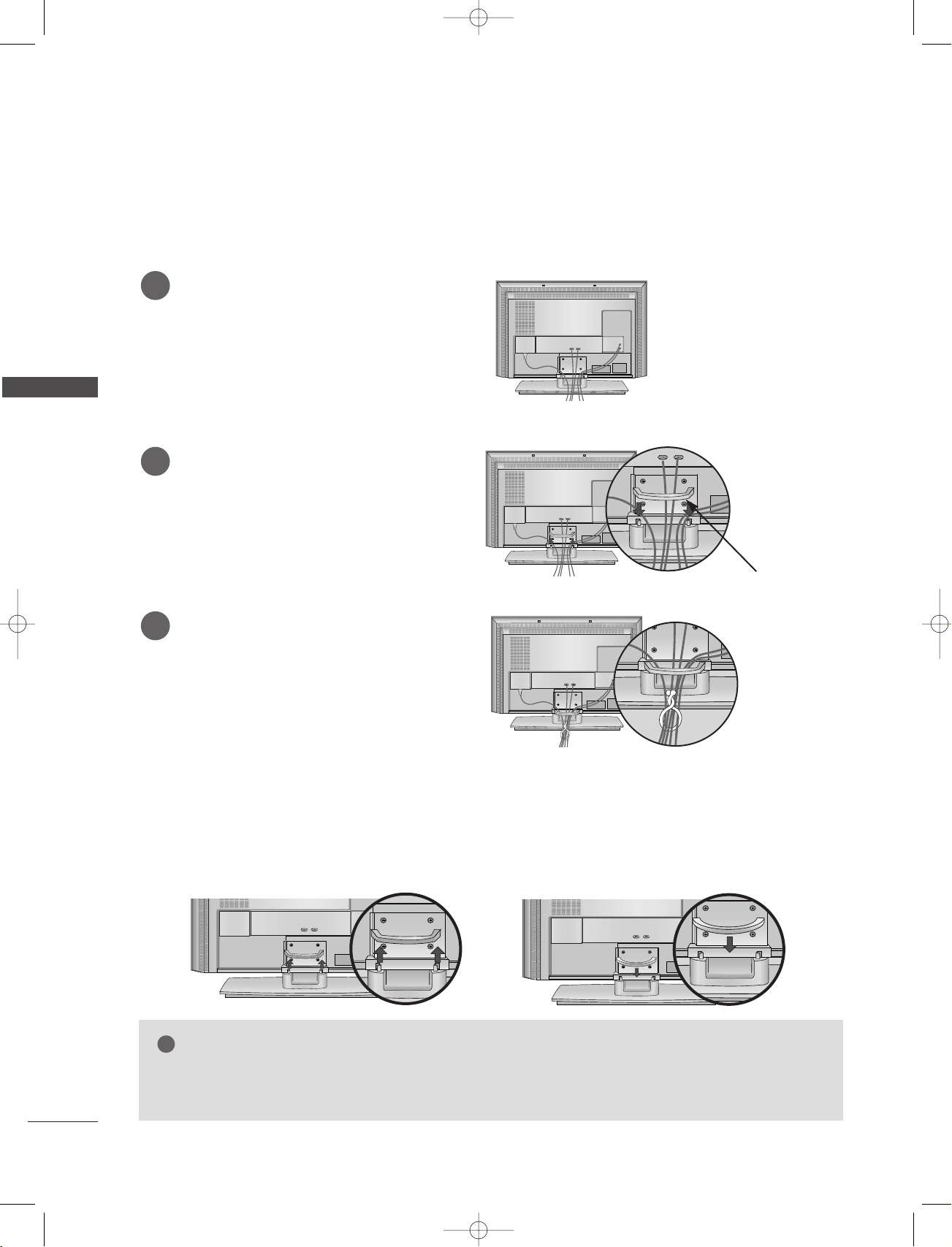
BASIC CONNECTION (42PC1RV
■
These models have two cable arrangement methods according to the stand type.
, 42PC3RV*, 42PC3RA*)
*
Stand type 1
Arrange the cables as shown picture.
Stand type 2
Hold the
1
hands and push it as shown.
CCAABBLLEE MMAA NNAAGGEEMMEENNTT
with both
INSTALLATION
Connect the cables as necessary.
2
To connect an additional equipment, see the
EExxtteerrnn aall eeqquuiippmmeenntt CCoonnnneeccttiioonnss
3
Reinstall the
shown.
CCAABBLLEE MMAANNAAGGEEMMEE NNTT
CABLE MANAGEMENT
section.
as
15
!
1-0323E_en_1-rev01 9/29/06 1:45 PM Page 16
INSTALLATION
BASIC CONNECTION
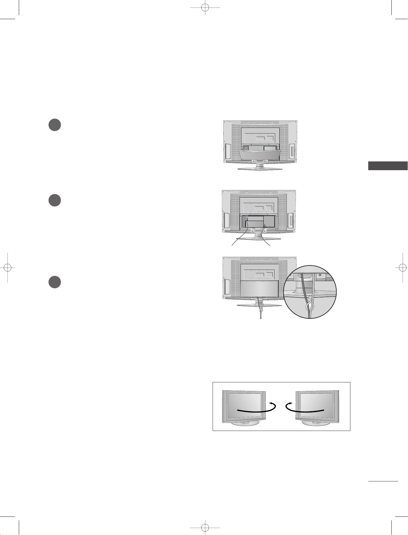
(Only 26LC2R*, 27LC2R*, 32LC2R*, 32LC25R*, 26LC3R*, 32LC3R*, 32LE2R*, 37LE2R*, 42LE2R*)
Connect the cables as necessary.
1
After connecting the cables neatly, arrange
the cables to the Cable Holder.
To connect an additional equipment, see the
EExxtteerrnnaall eeqquuiippmmeenntt CCoonnnneeccttiioonnss
tion.
INSTALLATION
sec-
Install the
2
as shown.
Bundle the cables using the supplied
3
twister holder.
CCAABBLLEE MMAANNAAGGEEMMEE NNTT
HOW TO REMOVE THE CABLE MANAGEMENT
- Hold the
- Hold the
CCAABBLLEE MMAANNAAGGEEMMEE NNTT
CCAABBLLEE MMAANNAAGGEEMMEE NNTT
with both hands and pull it upward.
with both hands and pull it downward. (Only 32LC3R*)
CABLE MANAGEMENT
NOTE
Do not hold the CABLE MANAGEMENT when moving the product.
GG
- If the product is dropped, you may be injured or the product may be broken.
16
Antenna
1-0323E_en_1-rev01 9/29/06 1:45 PM Page 17
BASIC CONNECTION (32LX2R
Hold the cover with both hands and pull
1
it backward.
Connect the cables as necessary.
2
To connect an additional equipment, see
EExxtteerrnnaall eeqquuiippmmeenntt CCoonnnneeccttiioonnss
the
section.
)
*
INSTALLATION
Bundle the cables using the supplied
3
twister holder.
SWIVEL STAND (32LX2R
The TV can be conveniently swiveled on its stand 30°
to the left or right to provide the optimum viewing
angle.
)
*
17
1-0323E_en_1-rev01 9/29/06 1:45 PM Page 18
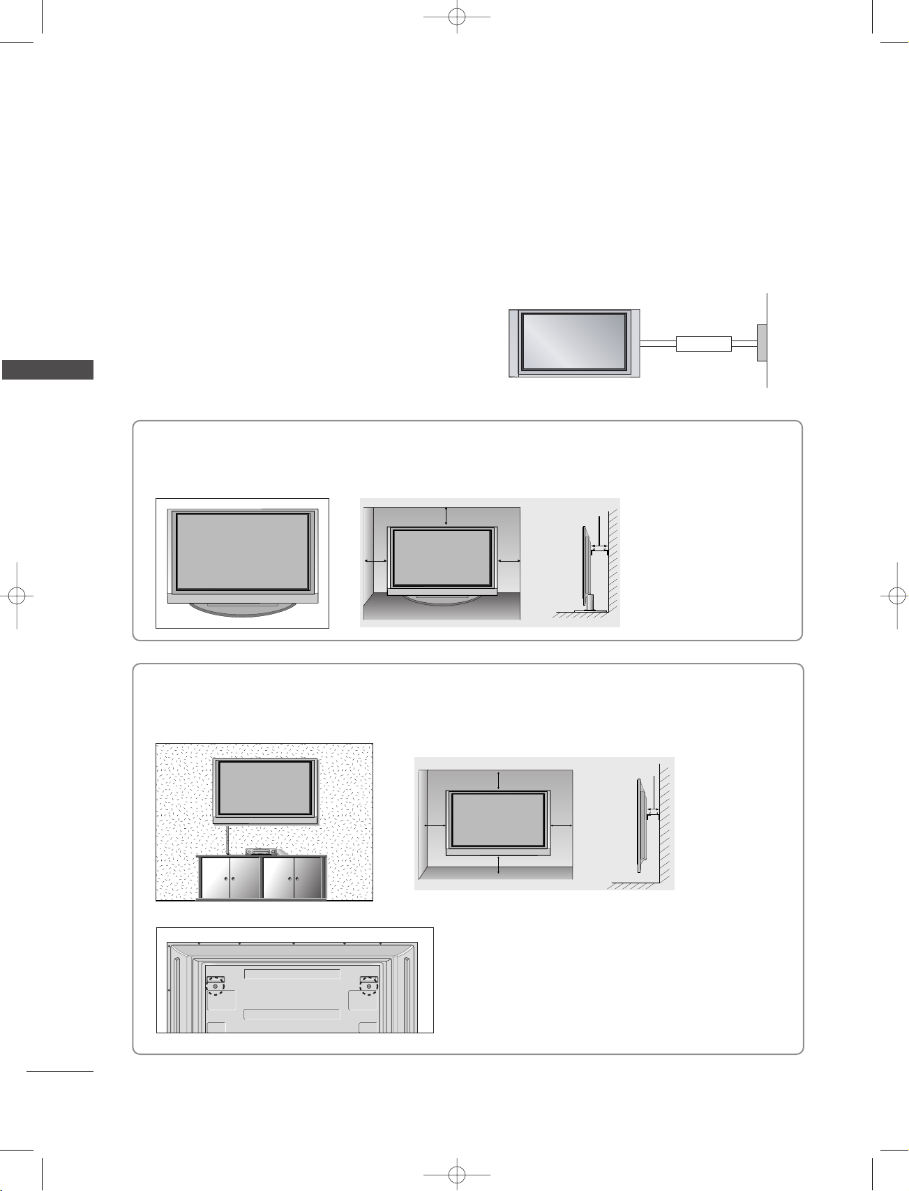
INSTALLATION
■
The TV can be installed in various ways such as on a wall, or on a desktop etc.
■
The TV is designed to be mounted horizontally.
INSTALLATION
GROUNDING
Ensure that you connect the earth ground wire to prevent
possible electric shock. If grounding methods are not possible, have a qualified electrician install a separate circuit
breaker. Do not try to ground the unit by connecting it to
telephone wires, lightening rods, or gas pipes.
Desktop Pedestal Installation
For proper ventilation, allow a clearance of 4" on each side and from the wall.
4 inches
4 inches4 inches
Wall Mount: Horizontal installation
Power
Supply
Short-circuit
Breaker
4 inches
18
For proper ventilation, allow a clearance of 4" on each side and from the wall. Detailed installation instructions are available from your dealer, see the optional Tilt Wall Mounting Bracket Installation and Setup Guide.
4 inches
4 inches
4 inches
4 inches
4 inches
<<OOnnllyy 4422PPCC11RRVV*,, 4422PPCC33RRVV*,, 4422PPCC33RRAA*sseerriieess>>
Remove two screws of the backside of the set before
installing the wall mounting bracket.
!
1-0323E_en_1-rev01 9/29/06 1:45 PM Page 19
HOW TO JOIN THE PRODUCT ASSEMBLY TO THE WALL TO
PROTECT THE SET TUMBLING
■
Set it up close to the wall so the product doesn’t fall over when it is pushed backwards.
■
The instructions shown below is a safer way to set up the product, which is to fix it on the wall so the
product doesn’t fall over when it is pulled in the forward direction. It will prevent the product from
falling for-ward and hurting people. It will also prevent the product from damage caused by fall. Please
make sure that children don’t climb on or hang from the product.
Plasma TV models LCD TV models
1
1
2
Use the eye-bolts or TV brackets/bolts to fix the product to the wall as shown in the picture.
1
(If your product has the bolts in the eye-bolts position before inserting the eye-bolts, loosen the bolts.)
* Insert the eye-bolts or TV brackets/bolts and tighten them securely in the upper holes.
Secure the wall brackets with the bolts (not provided as parts of the product, must purchase sepa-
2
rately) on the wall. Match the height of the bracket that is mounted on the wall.
3
INSTALLATION
2
Use a sturdy rope (not provided as parts of the product, must purchase separately) to tie the
3
product. It is safer to tie the rope so it becomes horizontal between the wall and the product.
NOTE
When moving the product to another place undo the ropes first.
GG
Use a product holder or a cabinet that is big and strong enough for the size and weight of the product.
GG
To use the product safely make sure that the height of the bracket that is mounted on the wall is same
GG
as that of the product.
19
ANTENNA
IN
1-0323E_en_1-rev01 9/29/06 1:45 PM Page 20
CONNECTIONS & SETUP
■
To prevent the equipment damage, never plug in any power cords until you have finished connecting all equipment.
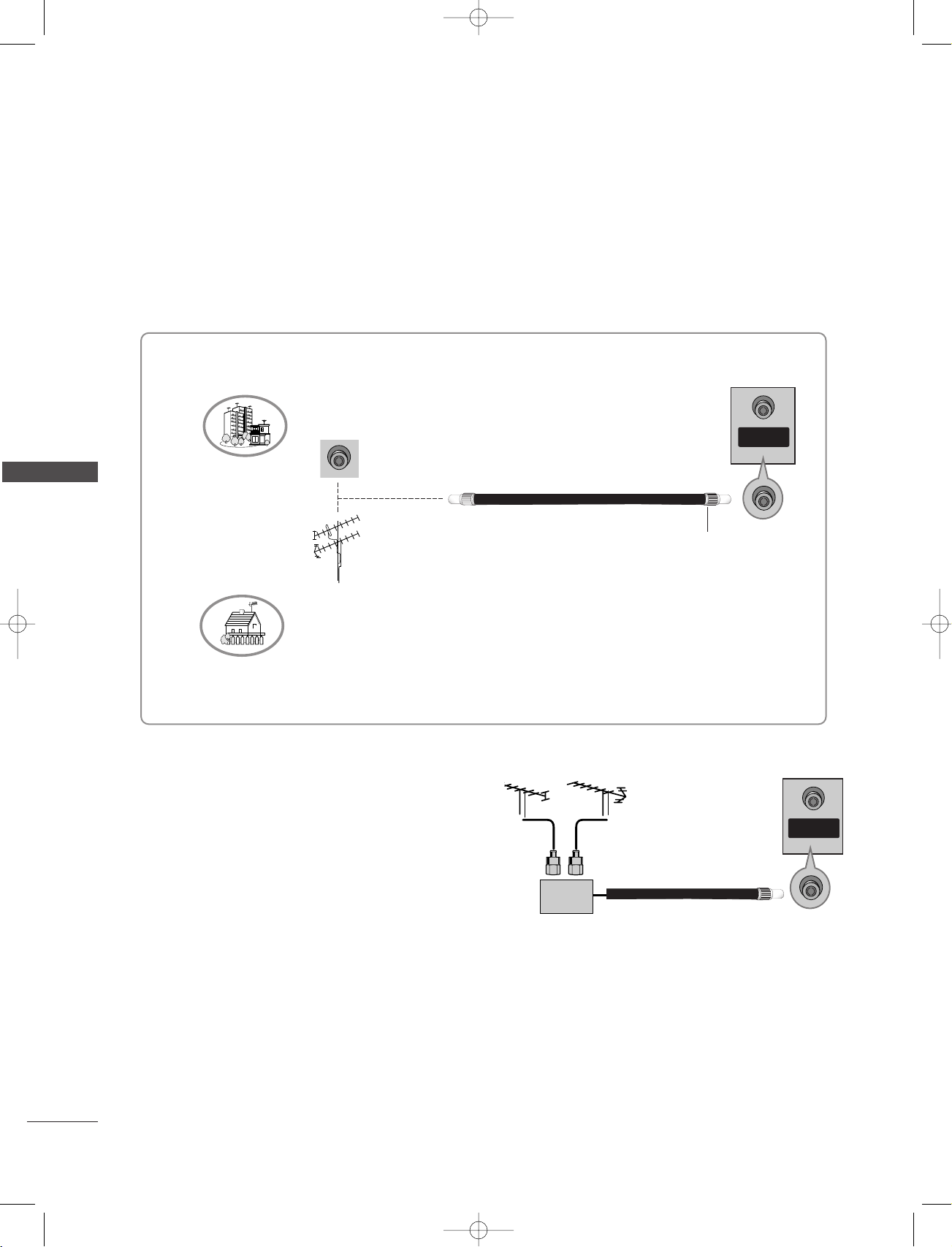
ANTENNA CONNECTION
■
For optimum picture quality, adjust antenna direction.
■
An antenna cable and converter are not supplied.
Multi-family Dwellings/Apartments
(Connect to wall antenna socket)
Wall Antenna Socket
CONNECTIONS & SETUP
VHF Antenna
UHF Antenna
Outdoor Antenna
Single-family Dwellings /Houses
(Connect to wall jack for outdoor antenna)
■
In poor signal areas, to get better picture
quality, install a signal amplifier to the
antenna as shown to the right.
■
If signal needs to be split for two TVs, use
an antenna signal splitter for connection.
RF Coaxial Wire (75 ohm)
Turn clockwise to tighten.
VHF
SSiiggnnaall
AAmmpplliiffiieerr
UHF
ANTENNA
IN
20
S-VIDEO
OUT
IN
(R) AUDIO (L) VIDEO
34
OUTPUT
SWITCH
ANT OUT
ANT IN
HDMI INHDMI IN
AUDIO OUTUDIO OUT
VARIABLE
ANTENNAANTENNA
IN
S-VIDEO
OUT
IN
(R) AUDIO (L) VIDEO
34
OUTPUT
SWITCH
ANT OUT
ANT IN
VIDEO
AUDIO
COMPONENT IN
AV 1 AV 2
VIDEO
S-VIDEO
MONO
( )
AUDIO
AV IN 3
HDMI IN
AUDIO OUT
VARIABLE
ANTENNA
IN
!
1-0323E_en_1-rev01 9/29/06 1:45 PM Page 21
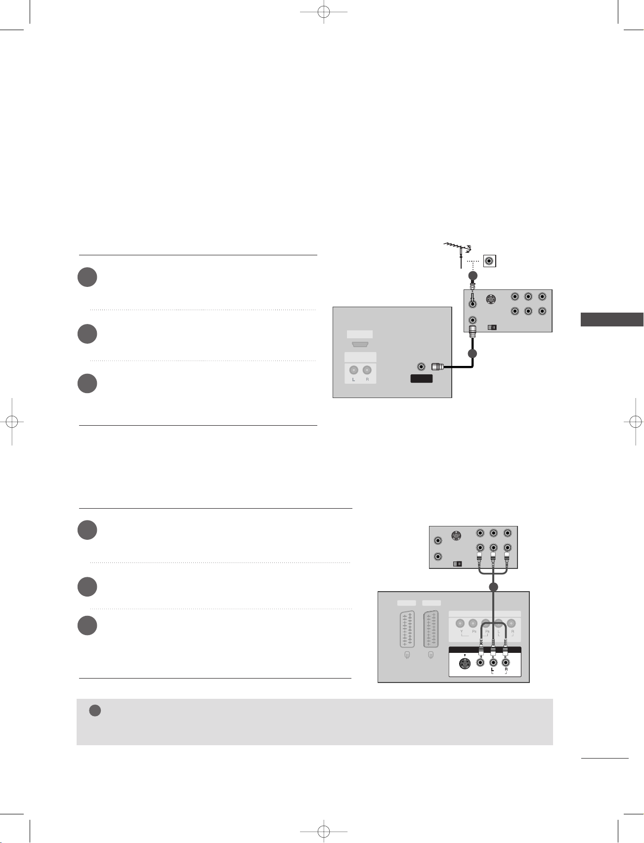
VCR SETUP
■
To avoid picture noise (interference), leave an adequate distance between the VCR and TV.
■
Typically a frozen still picture from a VCR. If the 4:3 picture format is used; the fixed images on the sides
of the screen may remain visible on the screen.
When connecting with an antenna
Connect the
1
AANNTTEENNNNAA IINN
Connect the antenna cable to the
2
socket of the VCR.
Press the
3
appropriate programme between the TV and VCR
AANNTT OOUUTT
socket of the VCR to the
socket on the set.
PPLLAAYY
button on the VCR and match the
AANNTT IINN
for viewing.
When connecting with a RCA cable
Connect the
1
Match the jack colors (Video = yellow, Audio Left = white,
and Audio Right = red).
AAUUDDII OO/VV IIDDEEOO
jacks between TV and VCR.
VVCCRR
2
VVCCRR
CONNECTIONS & SETUP
1
Insert a video tape into the VCR and press PLAY on the
2
VCR. (Refer to the VCR owner’s manual.)
AA VV33
Select
3
remote control.
- If connected to
input source using the
AAVV IINN 44
IINNPPUUTT
button on the
, select AV 4 input source.
1
(except 42PC3RV*, 42PC3RA*)
NOTE
If you have a mono VCR, connect the audio cable from the VCR to the
GG
AAUUDDIIOO LL//MMOONNOO
jack of the set.
21
S-VIDEO
OUT
IN
(R) AUDIO (L) VIDEO
34
OUTPUT
SWITCH
ANT OUT
ANT IN
VIDEO
AUDIO
COMPONENT IN
AV 1 AV 2
VIDEO
S-VIDEO
MONO
( )
AUDIO
AV IN 3
VIDEO
S-VIDEO
( )
AUDIO
AV IN 3
HDMI IN
AUDIO OUT
VARIABLE
ANTENNA
IN
VIDEO
AUDIO
COMPONENT IN
AV 1V 1 AV 2V 2
MONO
( )
AUDIO
VIDEO
S-VIDEO
AV IN 3
(R) AUDIO (L)
AUDIO/
VIDEO
!
!
1-0323E_en_1-rev01 9/29/06 1:45 PM Page 22
CONNECTIONS & SETUP
VCR SETUP
When connecting with a Euro Scart
CONNECTIONS & SETUP
Connect the Euro scart socket of the VCR to the
1
Euro scart socket on the set.
AA VV11
Insert a video tape into the VCR and press PLAY on the
2
VCR. (Refer to the VCR owner’s manual.)
1
AAVV11
Select
3
the remote control.
- If connected to
source.
input source with using the
AA VV22
Euro scart socket, select
IINNPPUUTT
button on
AV 2 input
VVCCRR
NOTE
If the S-VIDEO(Y/C) signal is received through the Euro scart socket 2 (AV2), you must change to the S-
GG
Video2 mode.
If you want to use the EURO scart cable, you have to use the signal shielded Euro scart cable.
GG
When connecting with an S-Video cable
22
1
2
3
4
Connect the S-VIDEO output of the VCR to the
input on the set. The picture quality is improved; com-
SS--VVIIDDEEOO
VVCCRR
pared to normal composite (RCA cable) input.
Connect the audio outputs of the VCR to the
input jacks on the set.
AAUUDDII OO
1
2
Insert a video tape into the VCR and press PLAY on the
VCR. (Refer to the VCR owner’s manual.)
Select AV 3 input source with using the
IINNPPUUTT
button on
the remote control.
NOTE
If both S-VIDEO and VIDEO sockets have been conneced to the S-VHS VCR simultaneously, only the S-
GG
VIDEO can be received.
AV IN 4V IN 4
L/MONOMONO
R
AUDIOAUDIO
VIDEOVIDEO
RL
AUDIO VIDEO
1-0323E_en_1-rev01 9/29/06 1:45 PM Page 23
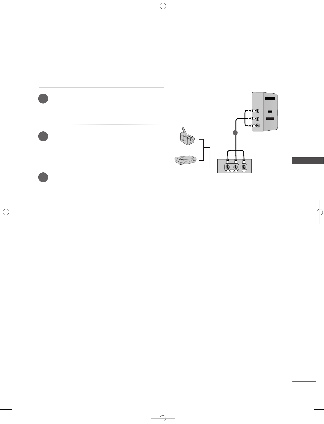
EXTERNAL EQUIPMENT CONNECTIONS
Connect the
1
and external equipment. Match the jack colors
AAUUDDII OO/VV IIDDEEOO
jacks between TV
(Video = yellow, Audio Left = white, and Audio Right
= red)
Select
2
button on the remote control. (except 42PC3RV*,
AV 4 input source with using the
42PC3RA*)
- If connected to
AAVV IINN33
input, select
source.
Operate the corresponding external equipment.
3
Refer to external equipment operating guide.
IINNPPUUTT
AV 3 input
Camcorder
Video Game Set
1
CONNECTIONS & SETUP
23
RGB IN
(PC/DTV)
RS-232C IN
(CONTROL & SERVICE)
AUDIO OUT
VARIABLE
HDMI IN
MONO
( )
AUDIO
VIDEO
S-VIDEO
AV IN 3
AV 1 AV 2
VIDEO
AUDIO
COMPONENT IN
B
R
(R) AUDIO (L)
VIDEO
AUDIO
COMPONENT IN
AV 1V 1 AV 2
MONO
( )
AUDIO
VIDEO
S-VIDEO
AV IN 3
(R) AUDIO (L)
AUDIO/
VIDEO
!
!
1-0323E_en_1-rev01 9/29/06 1:45 PM Page 24
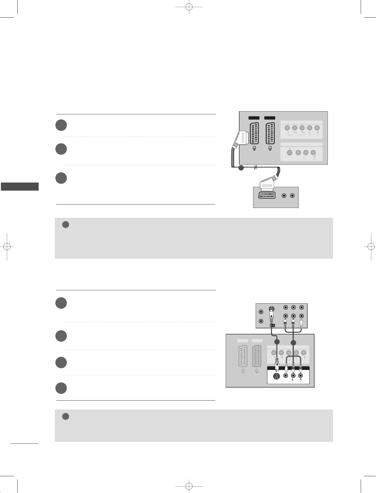
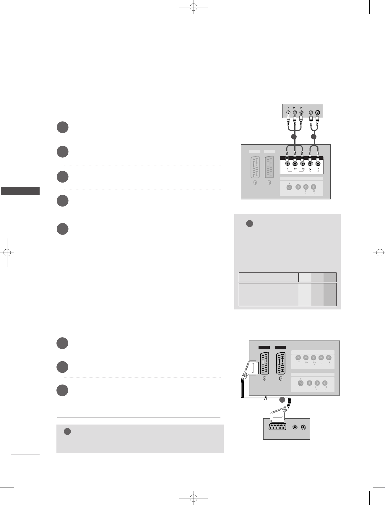
CONNECTIONS & SETUP
DVD SETUP
CONNECTIONS & SETUP
When connecting with a component cable
Connect the video outputs (Y, P
1
CCOOMMPPOONNEENNTT IINN VVIIDDEEOO
Connect the audio outputs of the DVD to the
2
NNEENNTT IINN AAUUDDIIOO
Turn on the DVD player, insert a DVD.
3
CCoommppoonneenntt
Select
4
jacks on the set.
input source with using the
button on the remote control.
Refer to the DVD player's manual for operating instruc-
5
tions.
B, PR) of the DVD to the
jacks on the set.
CCOOMMPP OO--
IINNPPUUTT
DDVVDD
1
2
NOTE
CCoommppoonneenntt IInnppuutt ppoorrttss
GG
To get better picture quality,
connect a DVD player to the
component input ports as shown
below.
When connecting with a Euro Scart
Connect the Euro scart socket of the DVD to the
1
Euro scart socket on the set.
Turn on the DVD player, insert a DVD.
2
Select AV 1 input source with using the
3
the remote control.
- If connected to
source.
NOTE
PPlleeaassee uussee tthhee sshhiieelldd ssccaarrtt ccaabbllee..
GG
AA VV22
Euro scart socket, select
IINNPPUUTT
button on
AV 2 input
AA VV11
Component ports on the TV
Video output ports
on DVD player
1
DVD
Y P
Y
Y
Y
Y
Pb
B-Y
Cb
P
P
R
B
Pr
R-Y
Cr
PR
B
24
RGB IN
(PC/DTV)
RS-232C IN
(CONTROL & SERVICE)
AUDIO OUT
VARIABLE
HDMI IN
AV 1 AV 2
VIDEO
AUDIO
COMPONENT IN
MONO
( )
AUDIO
VIDEO
S-VIDEO
AV IN 3
VIDEO
AUDIO
COMPONENT IN
S-VIDEO
(R) AUDIO (L)
REMOTE
CONTROL IN
AUDIO IN
(RGB)
RGB INRGB IN
(PC/DTV)
RS-232C INRS-232C IN
(CONTROL & SERSERVICE)VICE)
AUDIO OUTUDIO OUT
VARIABLE
HDMI IN
HDMI-DVD OUTPUT
!
1-0323E_en_1-rev01 9/29/06 1:45 PM Page 25
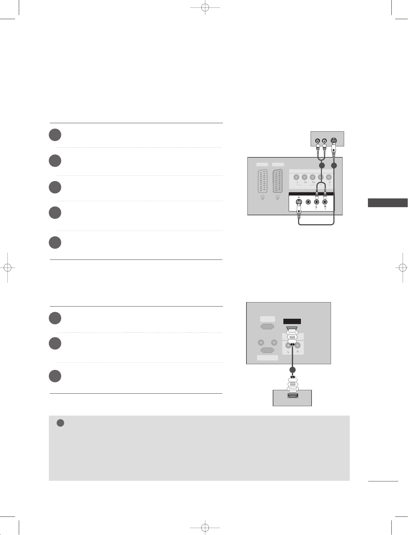
When connecting with a S-Video cable
Connect the S-VIDEO output of the DVD to the
1
input on the set.
Connect the audio outputs of the DVD to the
2
input jacks on the set.
Turn on the DVD player, insert a DVD.
3
Select AV 3 input source with using the
4
IINNPPUUTT
SS--VVIIDDEEOO
AAUUDDII OO
button on
the remote control.
Refer to the DVD player's manual for operating instruc-
5
tions.
When connecting with a HDMI cable
DDVVDD
2
1
CONNECTIONS & SETUP
Connect the HDMI output of the DVD to the
1
jack on the set.
Select
2
HDMI input source with using the
on the remote control.
Refer to the DVD player's manual for operating instructions.
3
HHDDMMII IINN
IINNPPUUTT
button
11
DDVVDD
NOTE
TV can receive the video and audio signal simultaneously with using a HDMI cable.
GG
GG
GG
If the DVD supports Auto HDMI function, the DVD output resolution will be automatically set to
1280x720p.
If the DVD does not support Auto HDMI, you need to set the output resolution appropriately. To get the
best picture quality, adjust the output resolution of the DVD to 1280x720p.
25
RGB IN
(PC/DTV)
RS-232C IN
(CONTROL & SERVICE)
AUDIO OUT
VARIABLE
HDMI IN
MONO
( )
AUDIO
VIDEO
S-VIDEO
AV IN 3
AV 1 AV 2
VIDEO
AUDIO
COMPONENT IN
B
R
(R) AUDIO (L)
RGB IN
(PC/DTV)(PC/DTV)
RS-232C IN
(CONTROL & SERVICE)
AUDIO OUTUDIO OUT
VARIABLE
HDMI INHDMI IN
REMOTE
CONTROL IN
AUDIO IN
(RGB)
(R) AUDIO (L)
DVI-DTV OUTPUT
!
!
1-0323E_en_1-rev01 9/29/06 1:45 PM Page 26
CONNECTIONS & SETUP
STB (SET-TOP BOX) SETUP
When connecting with a component cable
Connect the video outputs (Y, P
1
CCOOMMPPOONNEENNTT IINN VV IIDDEEOO
to the
B, PR) of the digital set-top box
jacks on the set.
DD iiggiittaall
SSeett --ttoo pp BBooxx
CONNECTIONS & SETUP
Connect the audio output of the digital set-top box to the
2
CCOOMMPPOONNEENNTT IINN AA UUDDIIOO
Turn on the digital set-top box. (Refer to the owner’s manual for
3
the digital set-top box.)
Select Component input source with using the
4
on the remote control.
NOTE
Signal
480i/576i
480p/576p/720p/1080i
jacks on the set.
Component
Yes
Yes
IINNPPUUTT
RGB-DTV
No
Yes
button
HDMI
No
Yes
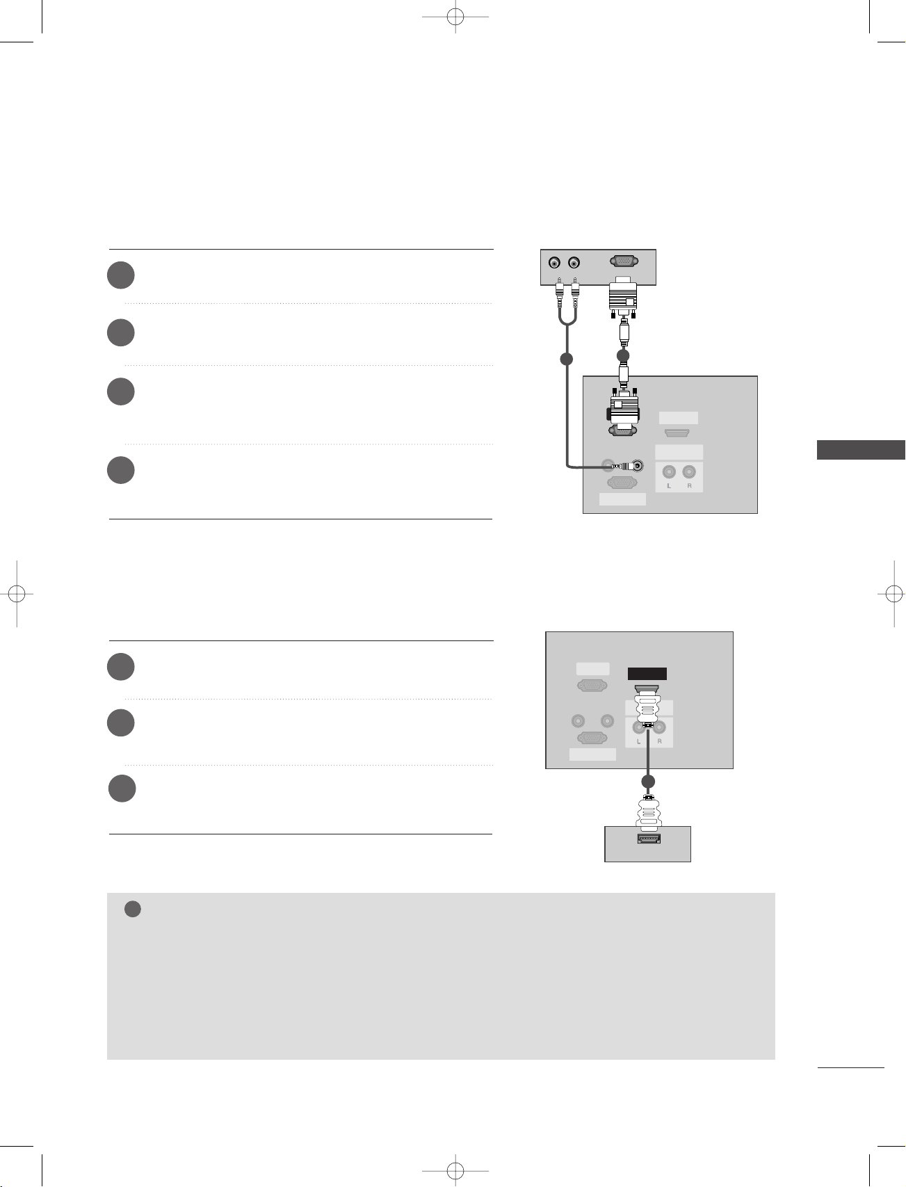
When connecting with a HDMI to DVI cable
Connect the DVI output of the digital set-top box to the
1
IINN
jack on the set.
Connect the audio outputs of the set-top box to the
2
IINN ((RRGG BB))
jack on the set.
HHDDMMII
AAUUDDII OO
1
1
2
Turn on the digital set-top box. (Refer to the owner’s manual for
3
the digital set-top box.)
Select HDMI input source with using the
4
remote control.
IINNPPUUTT
button on the
DDiiggiitt aall SSeett-- ttoopp
2
BB ooxx
NOTE
If the digital set-top box has a DVI output and no HDMI output, a separated audio connection is neces-
GG
26
sary.
If the digital set-top box supports Auto DVI function, the output resolution of the digital set-top box will
GG
be automatically set to 1280x720p.
If the digital set-top box does not support Auto DVI, you need to set the output resolution appropriately.
GG
To get the best picture quality, adjust the output resolution of the digital set-top box to 1280x720p.
(R) AUDIO (L)
RGB-DTV OUTPUT
REMOTE
CONTROL IN
RS-232C INRS-232C IN
(CONTR(CONTROL & SERSERVICE)VICE)
HDMI IN
AUDIO OUTUDIO OUT
VARIABLE
RGB INRGB IN
(PC/DTV)
AUDIO IN
(RGB)
RGB IN
(PC/DTV)
RS-232C IN
(CONTROL & SERVICE)
AUDIO OUT
VARIABLE
HDMI IN
REMOTE
CONTROL IN
AUDIO IN
(RGB)
RGB INRGB IN
(PC/DTV)
RS-232C INRS-232C IN
(CONTR(CONTROL & SERSERVICE)VICE)
AUDIO OUTUDIO OUT
VARIABLE
HDMI IN
HDMI-DVD OUTPUT
!
1-0323E_en_1-rev01 9/29/06 1:45 PM Page 27
When connecting with a D-sub 15 pin cable
Connect the RGB output of the digital set-top box to the
1
RR GGBB II NN ((PP CC//DDTTVV))
jack on the set.
Connect the audio outputs of the set-top box to the
2
AAUUDDIIOO IINN ((RRGGBB))
Turn on the digital set-top box. (Refer to the owner’s
3
jack on the set.
manual for the digital set-top box.)
Select RGB-DTV input source with using the
4
IINNPPUUTT
button on the remote control.
When connecting with a HDMI cable
Connect the HDMI output of the digital set-top box to the
1
HHDDMMII IINN
Select HDMI input source with using the
2
on the remote control.
jack on the set.
IINNPPUUTT
button
DD iiggiittaall
SSeett --ttoo pp BBooxx
2
1
CONNECTIONS & SETUP
3
Turn on the digital set-top box. (Refer to the owner’s man-
11
ual for the digital set-top box.)
DD iiggiittaall
SSeett --ttoo pp BBooxx
NOTE
TV can receive the video and audio signal simultaneously with using a HDMI cable.
GG
If the digital set-top box supports Auto HDMI function, output resolution of the digital set-top box will be
GG
automatically set to 1280x720p.
If the digital set-top box does not support Auto HDMI, you need to set the output resolution appropri-
GG
ately. To get the best picture quality, adjust the output resolution of the digital set-top box to
1280x720p.
27

!
REMOTE
CONTROL IN
RS-232C INRS-232C IN
(CONTR(CONTROL & SERVICE)
HDMI IN
AUDIO OUTUDIO OUT
VARIABLE
RGB INRGB IN
(PC/DTV)
AUDIO IN
(RGB)
RGB-PC OUTPUT
PC SOUND
1-0323E_en_1-rev01 9/29/06 1:45 PM Page 28
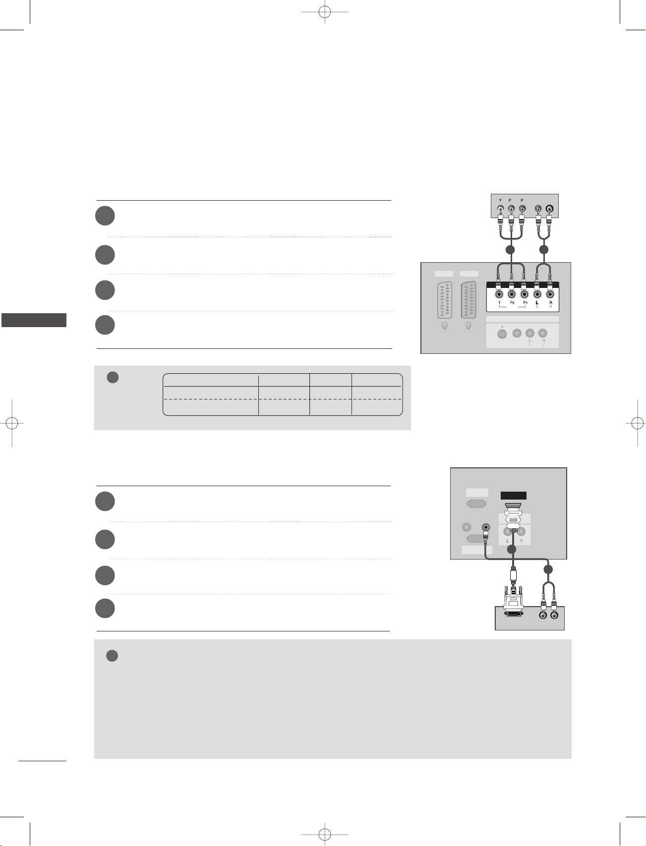
CONNECTIONS & SETUP
PC SETUP
■
This TV provides Plug and Play capability, meaning that the PC adjusts automatically to the TV's settings.
When connecting with a D-sub 15 pin cable
CONNECTIONS & SETUP
Connect the TV to the PC with the PC cable.
1
Connect the PC audio putput to the TV’s
2
((RRGGBB))
Turn on the PC.
3
Select RGB [PC] input source with using the
4
input.
ton on the remote control.
NOTE
1
To enjoy vivid picture and sound, connect a PC to
the set.
Avoid keeping a fixed image on the set’s screen
2
for a long period of time. The fixed image may
become permanently imprinted on the screen;
use a screen saver when possible.
3
Connect PC to the RGB INPUT(PC INPUT) port
of the set; change the resolution output of PC
accordingly.
44
There might be a noise according to some resolution, vertical pattern, contrast or brightness in
PC mode. Then change the PC mode into other
resolution or change the refresh rate into other
rate or adjust the brightness and contrast on the
menu until the picture is clean. If the refresh rate
of the PC graphic card can not be changed,
change the PC graphic card or consult it to the
manufacturer of the PC graphic card.
AAUUDDIIOO IINN
IINNPPUUTT
but-
55
6
7
8
9
PC
2
1
The synchronization input form for Horizontal
and Vertical frequencies is separate.
We recommend using 640x480, 60Hz (42PC1RV*,
42PC3RV*) /1360x768, 60Hz (26LC2R*,
27LC2R*, 32LC2R*, 32LC25R*, 26LC3R*,
32LC3R*, 32LX2R*, 32LE2R*, 37LE2R*, 42LE2R*)
/1024x768, 60Hz (42PC3RA*) for the PC mode,
they provide the best picture quality.
If the resolution of PC is over SXGA, there will be
no picture on the set.
Connect the audio cable from the PC to the
Audio input on the set. (Audio cables are not
included with the set).
When you use too long RGB-PC cable, there
might be a noise on the screen. We recommend
using under 5m of the cable. It provides the best
picture quality.
28

1-0323E_en_1-rev01 9/29/06 1:45 PM Page 29
Supported Display Resolution (RGB[PC] mode)
(26LC2R*/ 27LC2R*/ 32LC2R*/ 32LC25R*/
26LC3R*/ 32LC3R*/ 32LX2R*/ 32LE2R*/ 37LE2R*/
42LE2R*/ 42PC3RA*)
Resolution
640x350
720x400
640x480
800x600
1024x768
1280x768
1360x768
1366x768
Horizontal Vertical
Frequency(KHz) Frequency(Hz)
31.5 70.8
31.5 70.8
31.5 59.9
37.9 60.3
48.4 60.0
47.8 59.9
47.7 59.8
47.7 59.8
Supported Display Resolution (RGB[PC] mode)
(42PC1RV*/ 42PC3RV*)
Resolution
640x350
720x400
640x480
848x480
852x480
800x600
1024x768
Horizontal Vertical
Frequency(KHz) Frequency(Hz)
31.5 70.8
31.5 70.8
31.5 59.9
31.5 60.0
31.5 60.0
37.9 60.3
48.4 60.0
CONNECTIONS & SETUP
29

OK
INPUT
TVTV
INPUT
PIP PR- PIP PR+
PIP INPUT
DVD
ARC
EXIT
VOL
TIME
REVEAL
INDEX
Q.VIEW
MUTE
PR
SLEEP
LIST
I/II
MENU
TEXT PIP SIZE
POSTION
VCR
POWER
123
456
789
*
0
FAV
?
!
1-0323E_en_1-rev01 9/29/06 1:45 PM Page 30
CONNECTIONS & SETUP
TURNING THE TV ON
If your TV will be turned on, you will be able to use its features.
Turing on the TV
First, connect power cord correctly.
1
At this moment, the TV switches to standby mode.
■
In standby mode to turn TV on, press the ,
ton on the TV or press the
IINNPPUUTT, PPRR ++//--, NNuummbbeerr((00~99))
the TV will switch on.
IINNPPUUTT,PPRR
PPOOWWEERR, TTVV
,
button on the remote control and then
DD
but-
EE
//
CONNECTIONS & SETUP
Volume Adjustment
1
2
Press the
If you want to switch the sound off, press the
You can cancel this function by pressing the
button.
VVOOLL ++//--
button to adjust the volume.
Programme selection
1
Press the
PPRR ++//--
or NUMBER button to select a programme number.
MMUUTTEE
button.
MMUUTTEE, VVOOLL ++//--
or
II//IIII
NOTE
If you intend to be away on vacation, disconnect the power plug from
GG
wall power outlet.
30

!
1-0323E_en_1-rev01 9/29/06 1:45 PM Page 31
On-Screen Menu Language / Country Selection
Installation guide menu appears on TV screen when it is turned on for the first time.
1
2
Press the
language.
Press the
DD
// EE// F//
DD
// EE// F//
G button and then,
G button and then,
OOKK
button to select your desired
OOKK
button to select your country.
** IIff yyoouu wwaanntt ttoo cchhaannggee LLaanngguuaaggee// CCoouunnttrryy sseelleeccttiioonn
1
Press the
MMEENNUU
button and then use
DD
button to select the
EE
//
Special menu.
Press the GGbutton and then use
2
DD
button to select Language. The
EE
//
menus can be shown on the screen in the selected language.
Or, Press the
Press the
3
language or country.
Press the
4
GG
button and then use
GG
button and then use
OOKK
button
DD
DD
//
button to select Country.
EE
//
button to select your desired
EE
CONNECTIONS & SETUP
5
Press the
EEXXIITT
button to return to normal TV viewing.
NOTE
If you don’t finish set up
GG
IInnss ttaallllaattiioonn GGuuiiddee
by pressing
ton or time out of OSD (On Screen Display) display, it will continuously
appear until completing set up whenever the set is turned on.
If you select wrong local country, the teletext may not appear correctly
GG
on the screen and some problem may happen during teletext operation.
Arab and Hebrew are added to
GG
CCoouunnttrr yy
IInnss ttaallllaattiioonn GGuuiiddee
of
according to the countries which using Arab and Hebrew languages.
EEXX IITT
but-
31
32
SPECIAL FUNCTIONS
SPECIAL FUNTIONS
PIP (Picture-In-Picture)
INPUT
TVTV
INPUT
PIP PR- PIP PR+
PIP INPUT
DVD
ARC
TEXT PIP SIZE
POSTION
VCR
POWER
Watching PIP
Press the
PPII PP
button to access the sub picture.
Each press of PIP changes the PIP options.
PIP lets you view 2 different inputs (sources) on your TV screen at the same time.
One source will be large, and the other source will show a smaller inset image.
PIP function is available in the Component, RGB, HDMI mode. (But, it can’t
adjust 480i/576i resolution of Component, RGB, HDMI mode.)
PIP Mode DW2 Mode
PIP Off
Programme Selection for Sub Picture
Press the
PPIIPP PPRR ++//--
button to select a programme for the sub picture.
The selected programme number is displayed just below the programme number of main picture.
Input Source Selection for Sub Picture
Press the
PPIIPP IINNPPUUTT
button to select the input source for the sub picture.
Each press of
PPIIPP IINNPPUUTT
button is pressed, each input source for the sub picture is displayed.
(Sub picture can be selected only TV, AV1 (Video), AV2, S-Video2, AV3, AV4.)
Sub Picture Size Adjustment (PIP mode only)
Press the
SSII ZZEE
button to adjust the sub picture size.
With
SSII ZZEE
button in PIP mode, sub picture is adjusted.
Moving the Sub Picture (PIP mode only)
Press the
PPOOSSIITTIIOONN
button.
Repeatedly press the
PPOOSSIITTIIOONN
button then sub picture moves left.
0323A_en_1_rev10 2/23/97 1:22 PM Page 32

1-0323E_en_1-rev01 9/29/06 1:45 PM Page 33
TELETEXT
TThhiiss ffeeaattuurree iiss nnoott aavvaaiillaabbllee iinn aallll ccoouunnttrriieess..
Teletext is a free service broadcast by most TV stations which gives up-to-the-minute information on news,
weather, television programmes, share prices and many other topics.
The teletext decoder of this TV can support the SIMPLE, TOP and FASTEXT systems. SIMPLE (standard teletext) consists of a number of pages which are selected by directly entering the corresponding page number.
TOP and FASTEXT are more modern methods allowing quick and easy selection of teletext information.
Switch on/off
Press the
Two page numbers, TV station name, date and time are displayed on the screen headline. The first page number
indicates your selection, while the second shows the current page displayed.
Press the
TT EEXXTT
button to switch to teletext. The initial page or last page appears on the screen.
TT EEXXTT
or
EEXX IITT
button to switch off teletext. The previous mode reappears.
SIMPLE Text
PPaaggee sseelleeccttiioonn
AA
1
Enter the desired page number as a three digit number with the NUMBER buttons. If during selection you press
a wrong number, you must complete the three digit number and then re-enter the correct page number.
2
The
PPRR++//--
button can be used to select the preceding or following page.
SPECIAL FUNTIONS
33
i
1-0323E_en_1-rev01 9/29/06 1:45 PM Page 34
SPECIAL FUNCTIONS
TELETEXT
TOP Text
The user guide displays four fields-red, green, yellow and blue at the bottom of the screen. The yellow field
denotes the next group and the blue field indicates the next block.
BB lloocckk // ggrroouupp // ppaaggee sseelleeccttiioonn
AA
1
With the blue button you can progress from block to block.
2
Use the yellow button to proceed to the next group with automatic overflow to the next block.
3
With the green button you can proceed to the next existing page with automatic overflow to the next group.
Alternatively the
44
The red button permits to return to previous selection. Alternatively the
PPRR++
button can be used.
PPRR--
button can be used.
DD iirreecctt ppaaggee sseelleeccttiioonn
AA
Corresponding to the SIMPLE teletext mode, you can select a page by entering it as a three digit number using
SPECIAL FUNTIONS
the NUMBER buttons in TOP mode.
FASTEXT
The teletext pages are colour coded along the bottom of the screen and are selected by pressing the corresponding coloured button.
PPaaggee sseelleeccttiioonn
AA
1
Press the button to select the index page.
2
You can select the pages which are colour coded along the bottom line with the same coloured buttons.
3
Corresponding to the SIMPLE teletext mode, you can select a page by entering its three digit page number with
the NUMBER buttons in FASTEXT mode.
44
The
PPRR++//--
button can be used to select the preceding or following page.
34

?
1-0323E_en_1-rev01 9/29/06 1:45 PM Page 35
Special Teletext Functions
RR EEVVEEAALL
AA
Press this button to display concealed information, such as solutions of riddles or puzzles.
Press this button again to remove the information from the display.
SSII ZZEE
AA
Selects double height text.
Press this button to enlarge the top half of the page.
Press this button again to enlarge the bottom half of the page.
Press this button again to return to the normal display.
UUPP DDAATT EE
AA
Displays the TV picture on the screen while waiting for the new teletext page. The display will appear at the top
left hand corner of the screen. When the updated page is available then display will change to the page number.
Press this button to view the updated teletext page.
TT IIMMEE
AA
When viewing a TV programme, press this button to display the time at the top right hand corner of the screen.
Press this button again to remove the display. In the teletext mode, press this button to select a sub page number. The sub page number is displayed at the bottom of the screen. To hold or change the sub page, press the
RED/GREEN,
Press again to exit this function.
PPRR++//--
or NUMBER buttons.
SPECIAL FUNTIONS
HHOOLLDD
AA
Stops the automatic page change which will occur if a teletext page consists of 2 or more sub pages. The number of sub pages and the sub page displayed is, usually, shown on the screen below the time. When this button
is pressed the stop symbol is displayed at the top left-hand corner of the screen and the automatic page change
is inhibited. To continue press this button again.
35

!
1-0323E_en_2-rev01 9/29/06 1:49 PM Page 36
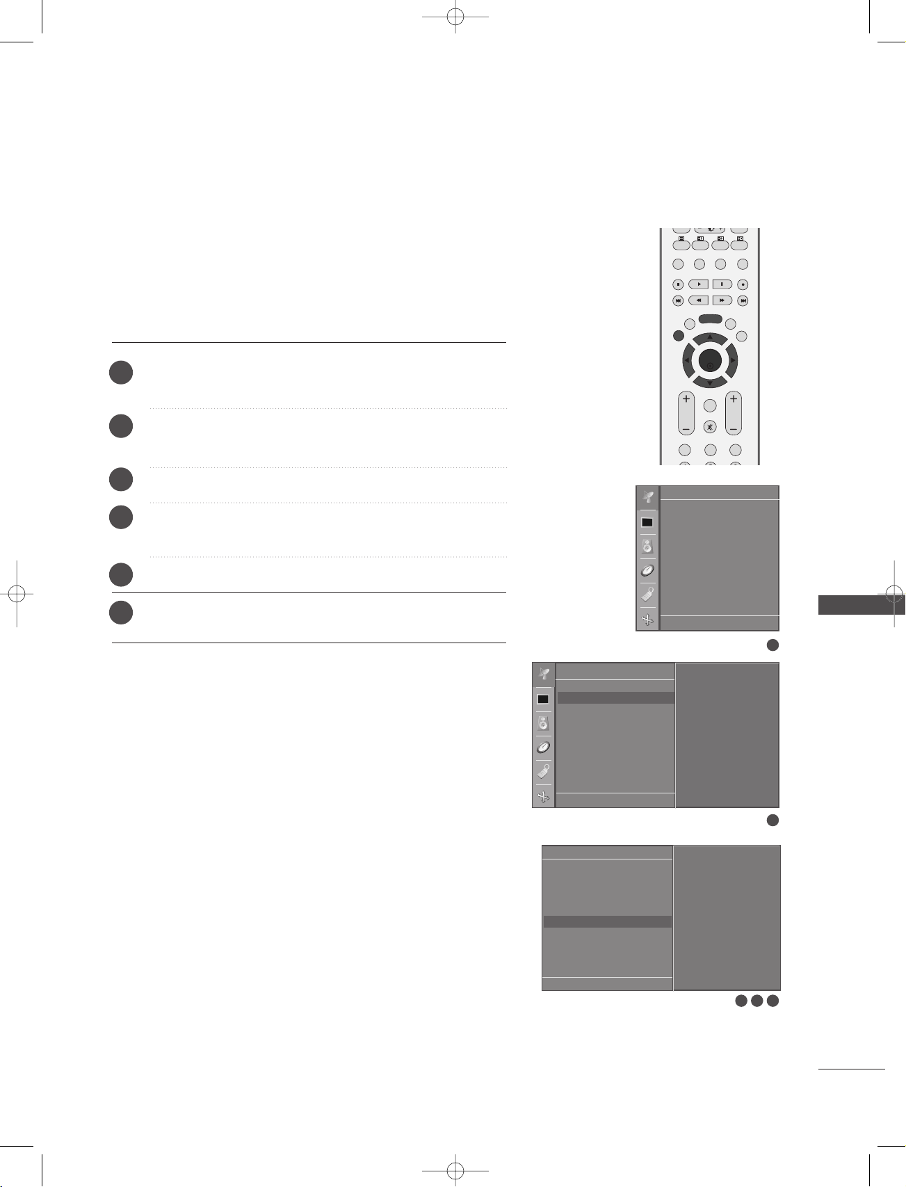
TV MENU
ON SCREEN MENUS SELECTION AND ADJUSTMENT
Your TV's OSD (On Screen Display)may differ slightly from what is shown in this manual.
The OSD mainly use pictures for the 42PC1RV*, 42PC3RV*, 42PC3RA*.
TV MENU
1
Press the
Press the
2
Change the setting of an item in the sub or pull-down menu with
3
MMEE NNUU
GG
button and then
button and then
DD/ EE
DD/ EE
button to display each menu.
button to select a menu item.
You can move to the higher level menu by pressing the
Station
Auto programme
Manual programme
Programme edit
Favourite programme
DE F G
OK MENU
SSttaa ttiioonn mmeennuu
* This menu differ with the model.
Picture
PSM
CSM
Advanced
Reset
DE F G
OK MENU
PPiicctt uurree mmee nnuu
F / G button.
OOKK
MMEE NNUU
or
* 42PC1RV*, 42PC3RV*,
42PC3RA*only
button.
Sound
SSM
AVL
Balance 0
Speaker
DE F G
OK MENU
SSoouunndd mmee nnuu
36
Screen
Auto config.
Manual config.
VGA Mode
ARC
Reset
DE F G
OK MENU
SSccrreeee nn mm ee nnuu
Special
Language
Country
Child lock
ISM Method
Low Power
Set ID
Demo
DE F G
OK MENU
SSppeecciiaall mmeennuu
Time
Clock
Off time
On time
Auto sleep
DE F G
TTiimmee mmee nnuu
OK MENU
NOTE
a. The OSD (On Screen Display) function enables you to adjust the screen status conveniently since it provides
graphical presentation.
b. In this manual, the OSD (On Screen Display) may be different from your TV’s because it is just example to help
the TV operation.
c. In the teletext mode, menus are not displayed

OK
PIP PR- PIP PR+
PIP INPUT
EXIT
VOL
Q.VIEW
PR
SLEEP
LIST
I/II
MENU
TEXT PIP SIZE
POSTION
1-0323E_en_2-rev01 9/29/06 1:49 PM Page 37
Setting up TV stations
AUTO PROGRAMME TUNING
Up to 100 TV stations can be stored by programme numbers (0 to 99).
Once you have preset the stations, you will be able to use the PR +/or NUMBER buttons to scan the stations you have programmed.
Stations can be tuned using automatic or manual modes.
All stations that can be received are stored by this method. It is recommended that you use auto programme during installation of this set.
.
1
2
Press the
MMEENNUU
Station menu.
GG
Press the
button and then
button and then
DD
//
DD
EE
button to select the
EE
//
button to select Auto
programme.
3
4
Press the
Press the
button and then
DD
button to select a TV system menu;
EE
//
BG : PAL B/G, SECAM B/G (Europe / East Europe / Asia / New
button to select System.
DD
EE
//
GG
Zealand / M.East / Africa / Australia)
I : PAL I/II (U.K. / Ireland / Hong Kong / South Africa)
DK : PAL D/K, SECAM D/K (East Europe / China / Africa / CIS)
L : SECAM L/L’ (France)
M : (USA / Korea / Philippines) (option)
5
6
Press the
Press the
DD
FF
button to select Storage from.
EE
//
//
GG
button or NUMBER buttons to select the
beginning programme number. If you use NUMBER buttons, any
number under 10 is entered with a numeric ‘0’ in front of it,
0055
i.e.‘
’ for 5.
7
Press the
DD
button to select Search.
EE
//
Station
Auto programme G
Manual programme
Programme edit
Favourite programme
DE F G
Auto programme
System G
Storage from
Search
OK MENU
Station
Auto programme
Manual programme
Programme edit
Favourite programme
DE F G
OK MENU
To set
BG
I
DK
L
1
TV MENU
2
GG
8
Press the
button to begin auto programming.
All receivable stations are stored.
To stop auto programming, press the
MMEENNUU
button.
When auto programming is completed, the Programme edit
menu appears on the screen. See the Programme edit section
to edit the stored programme.
9
Press the
EEXXIITT
button to return to normal TV viewing.
DE F G
OK MENU
3 4 5 6
Auto programme
C 05 BG
5 35%
MENU Stop
7
8
37

OK
PIP PR- PIP PR+
PIP INPUT
EXIT
VOL
Q.VIEW
MUTE
PR
SLEEP
LIST
I/II
MENU
TEXT PIP SIZE
POSTION
123
456
1-0323E_en_2-rev01 9/29/06 1:49 PM Page 38
TV MENU
Setting up TV stations
MANUAL PROGRAMME TUNING
Manual programme lets you manually tune and arrange the stations
in whatever order you desire.
Press the
1
Station menu.
2
Press the
programme.
3
Press the
4
Press the
desired programme number (0 to 99). If you use NUMBER
buttons, any number under 10 is entered with a numeric ‘0’ in
front of it, i.e. ‘
MMEENNUU
GG
GG
FF
button and then
button and then
button and then
//
GG
button or NUMBER buttons to select the
0055
’ for 5.
DD
EE
//
button to select Manual
DD
EE
//
//
DD
EE
button to select Storage.
button to select the
Station
Auto programme
Manual programme
Programme edit
Favourite programme
TV MENU
5
6
Press the
Press the
button to select System.
DD
EE
//
button to select a TV system menu;
DD
EE
//
BG : PAL B/G, SECAM B/G (Europe / East Europe / Asia / New
Zealand / M.East / Africa / Australia)
I : PAL I/II (U.K. / Ireland / Hong Kong / South Africa)
DK : PAL D/K, SECAM D/K (East Europe / China / Africa / CIS)
L : SECAM L/L’ (France)
M : (USA / Korea / Philippines) (option)
Press the
7
Press the
8
Press the
9
You can select the desired programme number with the
10
button or number buttons. If possible, select the programme
button to select Band.
DD
EE
//
button to select V/UHF or Cable.
DD
EE
//
button to select Channel.
DD
EE
//
number directly with the number buttons. Any number under 10
is entered with a numeric ‘0’ in front of it, i.e. ‘
11
12
Press the
Press the
button to select Search.
DD
EE
//
//
FF
GG
button to commence searching. If a station is
0055
found the search will stop.
Press the
13
To store another station, repeat steps 33to
14
Press the
15
OOKK
button to store it.
EEXXIITT
button to return to normal TV viewing.
1133
.
’ for 5.
DE F G
Station
Auto programme
Manual programme G
Programme edit
Favourite programme
DE F G
//
FF
GG
Manual programme
Storage G
System
Band
Channel
Fine
Search
Name
DE F G
OK MENU
OK MENU
To set
20
OK MENU
8 9
1
2
73 4 5 6
10 11 12
38
OK
PIP PR- PIP PR+
PIP INPUT
ARC
EXIT
VOL
Q.VIEW
MUTE
PR
SLEEP
LIST
I/II
MENU
TEXT PIP SIZE
POSTION
VCR
123
1-0323E_en_2-rev01 9/29/06 1:49 PM Page 39
FINE TUNING
Normally fine tuning is only necessary if reception is poor.
1
2
3
4
5
6
Press the
MMEENNUU
Station menu.
Press the
GG
button and then
programme.
Press the
Press the
GG
FF
and sound.
Press the
Press the
OOKK
EEXXIITT
button and then
button and then
//
GG
button to to fine tune for the best picture
DD
DD
//
DD
button to select the
EE
//
button to select Manual
EE
button to select Fine.
EE
//
button to store it.
button to return to normal TV viewing.
Station
Auto programme
Manual programme G
Programme edit
Favourite programme
Station
Auto programme
Manual programme
Programme edit
Favourite programme
DE F G
OK MENU
To set
TV MENU
1
DE F G
Manual programme
Storage
System
Band
Channel
Fine G
Search
Name
DE F G
OK MENU
OK MENU
2
F/G
3 4 5
39

OK
PIP PR- PIP PR+
PIP INPUT
ARC
EXIT
VOL
Q.VIEW
MUTE
PR
SLEEP
LIST
I/II
MENU
TEXT PIP SIZE
POSTION
VCR
123
1-0323E_en_2-rev01 9/29/06 1:49 PM Page 40
TV MENU
Setting up TV stations
ASSIGNING A STATION NAME
You can assign a station name with five characters to each programme number.
Press the
1
Station menu.
Press the
2
programme.
3
Press the
4
Press the
blank, ++, --, the number
MMEENNUU
GG
button and then
button and then
GG
button and then
GG
button and then
button to select the
EE
//
button to select Manual
EE
button to select Name.
EE
button. You can use a
DD
//
DD
DD//EE
DD
//
0 to 9 and the alphabet A to Z.
Station
Auto programme
Manual programme
Programme edit
Favourite programme
TV MENU
//
FF
GG
5
Press the
button to select the position and make
your choice of the second character, and so on.
6
7
Press the
Press the
OOKK
button to store it.
EEXXIITT
button to return to normal TV viewing.
Station
Auto programme
Manual programme G
Programme edit
Favourite programme
DE F G
Manual programme
Storage
System
Band
Channel
Fine
Search
Name G
DE F G
OK MENU
OK MENU
DE F G
To set
C 05
OK MENU
1
2
3 4 5 6
40

OK
PIP PR- PIP PR+
PIP INPUT
ARC
EXIT
VOL
Q.VIEW
MUTE
PR
SLEEP
LIST
I/II
MENU
TEXT PIP SIZE
POSTION
VCR
123
1-0323E_en_2-rev01 9/29/06 1:49 PM Page 41
PROGRAMME EDIT
This function enables you to delete or skip the stored programmes. Also you can move some stations to other programme
numbers or copy a blank station data into the selected programme number.
Press the
1
Station menu.
Press the
2
Programme edit.
Press the GGbutton to display the
3
MMEENNUU
DDeelleettiinngg aa pprrooggrraammmmee
AA
button and then
GG
button and then
1.Select a programme to be deleted with the
//
DD
// EE//
FF
2.Press the RED button twice.
The selected programme is deleted, all the following
programmes are shifted up one position.
CCooppyyiinngg aa pprrooggrraammmmee
AA
1.Select a programme to be copied with the
button.
2.Press the GREEN button.
All the following programmes are shifted down one position.
MMoovviinngg aa pprrooggrraammmmee
AA
1.Select a programme to be moved with the
button.
2.Press the YELLOW button.
3.Move the programme to the desired programme number
with the
DD
// EE//
4.Press the YELLOW button again to release this function.
SSkkiippppiinngg aa pprrooggrraammmmee nnuummbbeerr
AA
1.Select a programme number to be skipped with the
//
FF
GG
//
button.
2.Press the BLUE button. The skipped programme turns to blue.
3.Press the BLUE button again to release the skipped programme.
When a programme number is skipped it means that you
will be unable to select it using the
normal TV viewing. If you want to select the skipped pro
gramme, directly enter the programme number with the
NUMBER buttons or select it in the programme edit or
table menu.
4
Press the
EEXXIITT
button to return to normal TV viewing.
GG
FF
button.
//
GG
DD
DD
button to select the
EE
//
button to select
EE
//
Programme edit menu.
DD
DD
button.
button during
DD
EE
//
// EE//
// EE//
Station
Auto programme
Manual programme
Programme edit
Favourite programme
DE F G
//
FF
GG
Station
Auto programme
Manual programme
Programme edit G
//
FF
GG
DD
EE
//
Favourite programme
DE F G
OK MENU
Programme edit
0C03 5S69
1 BLN 03 6 S 17
2 C 12 7 S 22
3 S 66 8 C 09
4 S 67 9 C 11
Delete
Move
To set
DE F G
OK MENU
Copy
Skip
TV MENU
1
2
OK MENU
3
41

OK
EXIT
VOL
TIME
REVEAL
INDEX
Q.VIEW
MUTE
PR
SLEEP
LIST
I/II
MENU
123
456
789
*
10
FAV
?
1-0323E_en_2-rev01 9/29/06 1:49 PM Page 42
TV MENU
Setting up TV stations
FAVOURITE PROGRAMME
This function lets you select your favourite programmes directly.
Repeatedly press the
Press the
1
Station menu.
the
Press the
2
Favourite programme.
Press the GGbutton.
3
Press the
4
Select a desired programme with the
5
NUMBER buttons. Any number under 10 is entered with a
numeric ‘0’in front of it, i.e.‘
FFAAVV
button to select stored favourite programmes.
MMEE NNUU
GG
DD
button and then
button and then
button to select - - - - - - -.
EE
//
DD
00 55
//
’ for 5.
DD
EE
button to select
EE
//
button to select
//
FF
GG
button or
Station
Auto programme
Manual programme
Programme edit
Favourite programme
TV MENU
To store another programme, repeat steps
6
You can store up to 8 programmes.
Press the
7
EEXX II TT
button to return to normal TV viewing.
4 to 5.
Station
Auto programme
Manual programme
Programme edit
Favourite programme G
DE F G
OK MENU
DE F G
-- -----
-- -----
-- -----
-- -----
-- -----
-- -----
-- -----
-- -----
OK MENU
1
2 3 4 5
42
OK
PIP PR- PIP PR+
PIP INPUT
EXIT
VOL
Q.VIEW
MUTE
PR
SLEEP
LIST
I/II
MENU
TEXT PIP SIZE
POSTION
123
456
!
1-0323E_en_2-rev01 9/29/06 1:49 PM Page 43
CALLING THE PROGRAMME TABLE
You can check the programmes stored in the memory by displaying
the programme table.
DDiissppllaayyiinngg pprrooggrraammmmee ttaabbllee
AA
Press the
The programme table appears on the screen.
One programme table contains ten programmes as shown.
LLIISSTT
button to display the Programme table menu.
NOTE
a. You may find some blue programmes. They have been set up
to be skipped by auto programming or in the programme edit
mode.
b. Some programmes with the channel number shown in the pro-
gramme table indicate there is no station name assigned.
SSeelleeccttiinngg aa pprrooggrraammmmee iinn tthhee pprrooggrraammmmee ttaabbllee
AA
//
//
FF
Select a programme with the
Then press the
OOKK
button. The set switches to the chosen
DD
EE
//
programme number.
PPaaggiinngg tthhrroouugghh aa pprrooggrraammmmee ttaabbllee
AA
There are 10 programme table pages in which contain 100 programmes.
//
//
FF
Pressing the
Press the
LLIISSTT
DD
EE
//
button to return to normal TV viewing.
GG
button repeatedly turns the pages.
GG
button.
Programme List
0C03 5S69
1 BLN 03 6 S 17
2 C 12 7 S 22
3 S 66 8 C 09
4 S 67 9 C 11
FG DE
OK
TV MENU
43
OK
PIP PR- PIP PR+
PIP INPUT
EXIT
VOL
Q.VIEW
MUTE
PR
SLEEP
LIST
I/II
MENU
TEXT PIP SIZE
POSTION
123
456
1-0323E_en_2-rev01 9/29/06 1:49 PM Page 44
TV MENU
Picture Menu Options
PSM (Picture Status Memory)
DDyynnaa mmiicc
SSttaannddaarrdd
MM iilldd
UU sseerr 11//22
Press the
1
the
Press the
2
Select this option to display with a sharp image.
The most general and natural screen display status.
Select this option to display with a mild image.
Select this option to use the user-defined setting.
MMEENNUU
button and then
DD
//
Picture menu.
GG
button and then
DD
EE
//
button to select
EE
button to select PSM.
Picture
PSM
CSM
Advanced
Reset
TV MENU
3
Press the
GG
button and then
//
DD
EE
Dynamic, Standard, Mild, User 1, or User 2.
4
Press the
AA
PSM adjusts the TV for the best picture appearance.
EEXX II TT
button to return to normal TV viewing.
Select the preset value in the PSM menu based on the
programme category.
DD yynnaamm iicc, SSttaannddaarrdd
AA
and
MMiilldd
optimum picture reproduction at the factory and cannot
be changed.
button to select
, are programmed for
Picture
PSM G
CSM
Advanced
Reset
DE F G
OK MENU
DE F G
Dynamic
Standard
Mild
User 1
User 2
OK MENU
1
2 3
44
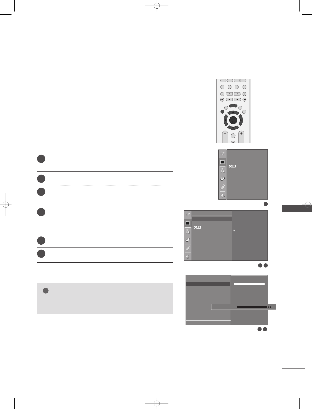
OK
PIP PR- PIP PR+
PIP INPUT
EXIT
VOL
Q.VIEW
PR
SLEEP
LIST
I/II
MENU
TEXT PIP SIZE
POSTION
!
1-0323E_en_2-rev01 9/29/06 1:49 PM Page 45
Picture Adjustment (PSM-User option)
CCoonnttrraasstt
BBrriigg hhttnneessss
CCoolloouurr
SShhaarrppnneess ss
Adjusts the difference between the light and dark levels in the picture.
Increases or decreases amount of white in the your picture.
Adjusts intensity of all colours.
Adjusts the level of crispness in the edges between the light and
dark areas of the picture. The lower the level, the softer the image.
TTiinntt
1
2
3
Adjusts the balance between red and green levels.
Press the
Picture menu.
the
Press the
Press the
1, or User 2.
Press the
4
desired picture option (
Sharpness, and Tint).
Press the
5
MMEE NNUU
GG
GG
GG
FF
button and then
button and then
button and then
button and then
//
GG
button to make appropriate adjustments.
DD
DD
EE
//
DD
EE
//
//
DD
EE
button to select
EE
//
button to select PSM.
button to select User
button to select the
Contrast, Brightness, Colour,
Picture
PSM G
CSM
Advanced
Reset
Picture
PSM
CSM
Advanced
Reset
DE F G
Dynamic
Standard
Mild
User 1
User 2
OK MENU
1
TV MENU
6
Press the
EEXX II TT
button to return to normal TV viewing.
NOTE
You can’t adjust colour, sharpness and tint in the RGB-
GG
PC mode to the levels you prefer.
DE F G
OK MENU
User 1
Contrast 100 G
Brightness 50
Colour 50
Sharpness 50
Tint 0
Contrast 85 F
E
DE F G
OK MENU
2 3
G
4 5
45
OK
PIP PR- PIP PR+
PIP INPUT
EXIT
VOL
Q.VIEW
MUTE
PR
SLEEP
LIST
I/II
MENU
TEXT PIP SIZE
POSTION
1-0323E_en_2-rev01 9/29/06 1:49 PM Page 46
TV MENU
Picture Menu Options
CSM (Colour Status Memory)
To initialize values (reset to default settings), select the
option.
Choose one of three automatic colour adjustments. Set to warm to
enhance hotter colours such as red, or set to cool to see less
intense colours with more blue.
1
2
3
Press the
the
Press the
Press the
either
MMEE NNUU
button and then
Picture menu.
GG
button and then
GG
button and then
DD
EE
//
DD
//
Cool, Normal, War m , or User.
DD
button to select
EE
//
button to select CSM.
button to select
EE
NNoorrmmaall
Picture
PSM
CSM
Advanced
Reset
TV MENU
4
Press the
EEXX II TT
button to return to normal TV viewing.
Picture
PSM
CSM G
Advanced
Reset
DE F G
OK MENU
DE F G
Cool
Normal
Warm
User
OK MENU
1
2 3
46

OK
PIP PR- PIP PR+
PIP INPUT
EXIT
VOL
Q.VIEW
MUTE
PR
SLEEP
LIST
I/II
MENU
TEXT PIP SIZE
POSTION
1-0323E_en_2-rev01 9/29/06 1:49 PM Page 47
Manual Colour Temperature Control
(CSM - User option)
To adjust red, green, blue to any colour temperature you prefer.
Press the
1
Picture menu.
the
Press the
2
Press the
3
Press the
4
Red, Green, or Blue.
Press the
5
Press the
6
MMEE NNUU
GG
GG
GG
FF
EEXX II TT
button and then
button and then
button and then
button and then
//
GG
button to make appropriate adjustments.
DD
EE
//
DD
DD
DD
button to select CSM.
EE
//
button to select User.
EE
//
button to select
EE
//
button to return to normal TV viewing.
button to select
Picture
PSM
CSM G
Advanced
Reset
DE F G
OK MENU
User
Red +30 G
Green 0
Blue 0
Picture
PSM
CSM
Advanced
Reset
DE F G
Cool
Normal
Warm
User
OK MENU
2 3
1
TV MENU
DE F G
OK MENU
Red +25 F
E
G
4 5
47

OK
PIP PR- PIP PR+
PIP INPUT
EXIT
VOL
Q.VIEW
MUTE
PR
SLEEP
LIST
I/II
MENU
TEXT PIP SIZE
POSTION
123
456
1-0323E_en_2-rev01 9/29/06 1:49 PM Page 48
TV MENU
Picture Menu Options
FUNCTION
XD is LG electronic's unique picture improving technology to display a
real HD source through an advanced digital signal processing algorithm.
It’s not available to use this function in RGB-PC mode.
Press the
1
the
Press the
2
Press the
3
Auto or Manual.
Press the
4
MMEE NNUU
Picture menu.
GG
button and then
button and then
GG
EEXX IITT
button to return to TV viewing.
button and then
DD
//
DD
//
DD
EE
EE
button to select
EE
//
button to select XD.
button to select
Picture
PSM
CSM
Advanced
Reset
TV MENU
** SSeelleeccttiinngg tthhee MMaannuuaall
This menu is activatived after selecting the
Press theGGbutton and then
1
2
3
Contrast,
Press the
Press the
XXDD CCoonnttrr aasstt ::
AA
XD Colour
button and then
GG
EEXX II TT
according to the brightness of the reflection.
XXDD CCoolloouurr ::
AA
automatically to reproduce as closely as possible to the
natural colors.
XXDD NNRR ::
AA
Removing the noise up to the point where it
does not damage the original picture. (
to use this function in HDMI, Component (except
480i/576i), RGB-DTV mode.)
button to return to normal TV viewing.
Optimizing the contrast automatically
Adjusting the colors of the reflection
DD
//
or XD NR.
DD
EE
//
button to select On or Off.
User1
or
User2
button to select
EE
It’s not available
of
PPSS MM
XX DD
.
Picture
PSM
CSM
Advanced
Reset
DE F G
Manual
XD Contrast G
XD Colour
XD NR
DE F G
OK MENU
OK MENU
DE F G
Auto
G
Manual
On
Off
OK MENU
1
2 3
1 2
48

OK
PIP PR- PIP PR+
PIP INPUT
EXIT
VOL
Q.VIEW
MUTE
PR
SLEEP
LIST
I/II
MENU
TEXT PIP SIZE
POSTION
123
1-0323E_en_2-rev01 9/29/06 1:49 PM Page 49
ADVANCED-CINEMA
Set up the TV for the best picture appearance for viewing
movies.
This feature operates only in Analog TV, AV, S-Video and
Component 480i/576i mode.
1
2
3
4
5
Press the
the
Picture menu.
Press the
Press the
Press the
GG
GG
GG
Press the
MMEE NNUU
EEXX II TT
button and then
button and then
button and then
button and then
DD
DD
DD
DD
//
button to select Advanced.
EE
//
button to select Cinema.
EE
//
button to select On or Off.
EE
//
button to return to normal TV viewing.
button to select
EE
Picture
PSM
CSM
Advanced G
Reset
DE F G
Advanced
Cinema G
Black Level
OK MENU
Picture
PSM
CSM
Advanced
Reset
DE F G
To set
On
Off
OK MENU
2 3
1
TV MENU
DE FG
OK MENU
4
49

OK
PIP PR- PIP PR+
PIP INPUT
EXIT
VOL
Q.VIEW
MUTE
PR
SLEEP
LIST
I/II
MENU
TEXT PIP SIZE
POSTION
123
1-0323E_en_2-rev01 9/29/06 1:49 PM Page 50
TV MENU
ADVANCED-BLACK LEVEL
When you watch the movie, this function adjusts the set to the
best picture appearance. Adjusting the contrast and the brightness of the screen using the black level of the screen.
This function works in the following mode: AV (NTSC-M), SVideo (NTSC-M) or HDMI.
TV MENU
1
2
3
4
5
Press the
Picture menu.
the
Press the
Press the
Level.
Press the
High.
LLooww
AA
AA
::
HHiigg hh
Press the
MMEE NNUU
GG
GG
GG
button and then
button and then
button and then
button and then
DD
button to select Advanced.
DD
EE
//
button to select Black
DD
EE
//
button to select Low or
DD
EE
//
button to select
EE
//
The reflection of the screen gets darker.
::
The reflection of the screen gets brighter.
EEXX II TT
button to return to normal TV viewing.
Picture
PSM
CSM
Advanced G
Reset
DE F G
OK MENU
Picture
PSM
CSM
Advanced
Reset
DE F G
To set
OK MENU
1
2 3
50
Advanced
Cinema
Black Level
DE
FG
OK MENU
Low
G
High
2 3

OK
PIP PR- PIP PR+
PIP INPUT
EXIT
VOL
Q.VIEW
MUTE
PR
SLEEP
LIST
I/II
MENU
TEXT PIP SIZE
POSTION
123
456
1-0323E_en_2-rev01 9/29/06 1:49 PM Page 51
RESET
1
2
3
Press the
the
Press the
Press the
MMEE NNUU
Picture menu.
GG
button and then
GG
button to initialize the adjusted value.
button and then
DD
//
DD
EE
button to select
EE
//
button to select Reset.
• Returns to the default settings PSM, CSM, XD, Advanced
at the factory.
Picture
PSM
CSM
Advanced
Reset G
Picture
PSM
CSM
Advanced
Reset
DE F G
To set
OK MENU
TV MENU
1
DE F G
OK MENU
2 3
51

OK
PIP PR- PIP PR+
PIP INPUT
EXIT
VOL
Q.VIEW
MUTE
PR
SLEEP
LIST
I/II
MENU
TEXT PIP SIZE
POSTION
123
456
1-0323E_en_2-rev01 9/29/06 1:49 PM Page 52
TV MENU
Sound Menu Options
SSM (Sound Status Memory)
You can select your preferred sound setting; Surround MAX, Flat,
Music, Movie or Sports and you can also adjust the sound frequency of the equalizer.
SSM lets you enjoy the best sound without any special adjustment
because the TV sets the appropriate sound options based on the
programme content.
SSuurrrroouu nndd MMaaxx, FF llaatt, MM uussiicc, MM oovviiee
for good sound quality at the factory and are not adjustable.
SSuurrrroouunndd MMaaxx
FF llaatt
MM uussiicc
The most commanding and natural audio.
Select this option to enjoy the original sound when lis
Select this option to sound realistic.
tening to the music.
MM oovviiee
SSppoorrttss
UU ssee rr
Select this option to enjoy sublime sound.
Select this option to watch sports broadcasting.
Select this option to use the user-defined audio set-
tings.
, and
SSppoorrttss
are preset
Sound
SSM
AVL
Balance 0
Speaker
TV MENU
1
2
3
Press the
the
Press the
Press the
MMEE NNUU
Sound menu.
button and then
GG
button and then
GG
button and then
DD
//
DD
//
DD
EE
//
button to select SSM.
EE
button to select
EE
Surround Max, Flat, Music, Movie, Sports or User.
4
Press the
EEXX II TT
button to return to normal TV viewing.
button to select
Sound
SSM G
AVL
Balance 0
Speaker
DE F G
OK MENU
DE F G
Surround MAX
Flat
Music
Movie
Sports
User
OK MENU
1
2 3
52
OK
PIP PR- PIP PR+
PIP INPUT
EXIT
VOL
Q.VIEW
MUTE
PR
SLEEP
LIST
I/II
MENU
TEXT PIP SIZE
POSTION
1-0323E_en_2-rev01 9/29/06 1:49 PM Page 53
Sound Frequency Adjustment
(SSM - User option)
Adjust the sound equalizer.
Press the
1
the
Press the
2
Press the
3
Press the
4
Select a sound band by pressing the
5
MMEE NNUU
Sound menu.
GG
button and then
GG
button and then
GG
button.
button and then
Make appropriate sound level with the
6
Press the
EEXX II TT
button to return to normal TV viewing.
DD
DD
EE
//
DD
EE
//
button to select
EE
//
button to select SSM.
button to select User.
//
FF
GG
button.
//
EE
button.
DD
Sound
SSM G
AVL
Balance 0
Speaker
DE F G
OK MENU
Sound
SSM
AVL
Balance 0
Speaker
DE F G
OK MENU
Surround MAX
Flat
Music
Movie
Sports
User
2 3 4
1
TV MENU
User
0.1 0.5 1.5 5.0 10 kHz
DE F G
OK MENU
5
53

OK
PIP PR- PIP PR+
PIP INPUT
EXIT
VOL
Q.VIEW
PR
SLEEP
LIST
I/II
MENU
TEXT PIP SIZE
POSTION
1-0323E_en_2-rev01 9/29/06 1:49 PM Page 54
TV MENU
Sound Menu Options
AVL (Auto Volume Leveler)
AVL automatically keeps on an equal volume level even if you
change programmes.
1
2
3
Press the
the
Press the
Press the
MMEE NNUU
Sound menu.
button and then
GG
button and then
GG
button and then
DD
//
DD
EE
//
DD
EE
button to select
EE
//
button to select AV L.
button to select On or Off.
Sound
SSM
AVL
Balance 0
Speaker
TV MENU
4
Press the
EEXX II TT
button to return to normal TV viewing.
Sound
SSM
AVL G
Balance 0
Speaker
1
DE F G
OK MENU
DE F G
On
Off
OK MENU
1
2 3
54

OK
PIP PR- PIP PR+
PIP INPUT
EXIT
VOL
Q.VIEW
PR
SLEEP
LIST
I/II
MENU
TEXT PIP SIZE
POSTION
1-0323E_en_2-rev01 9/29/06 1:49 PM Page 55
BALANCE ADJUSTMENT
You can adjust the sound balance of speaker to the levels you
prefer.
Press the
1
the
Sound menu.
Press the
2
Press the
3
desired adjustment.
Press the
4
MMEE NNUU
GG
GG
EEXX II TT
button and then
button and then
button and then
button to return to normal TV viewing.
DD
button to select Balance.
DD
EE
//
//
FF
GG
button to select
EE
//
button to make
Sound
SSM
AVL
Balance R15 G
Speaker
1
DE F G
OK MENU
Sound
SSM
AVL
Balance 0
Speaker
DE F G
OK MENU
2 3
1
TV MENU
55

OK
PIP PR- PIP PR+
PIP INPUT
EXIT
SLEEP
LIST
I/II
MENU
TEXT PIP SIZE
POSTION
1-0323E_en_2-rev01 9/29/06 1:49 PM Page 56
TV MENU
Sound Menu Options
SPEAKER
You can adjust the internal speaker status.
In AV, COMPONENT, RGB[PC], RGB[DTV] and HDMI mode, internal speaker audio can be outputted even though there is no video
signal.
If you want to use your external hi-fi stereo system, turn off the
internal speakers of the set.
1
2
Press the
the
Press the
MMEE NNUU
Sound menu.
button and then
GG
button and then
DD
EE
//
DD
button to select
EE
//
button to select
Speaker
Sound
SSM
AVL
Balance 0
Speaker
.
TV MENU
3
4
Press the
On or Off.
Press the
button and then
GG
EEXX II TT
button to return to normal TV viewing.
DD//EE
button to select
Sound
SSM
AVL
Balance 0
Speaker G
1
DE F G
OK MENU
DE F G
On
Off
OK MENU
1
2 3
56

OK
INPUT
TVTV
INPUT
PIP PR- PIP PR+
PIP INPUT
DVD
ARC
EXIT
VOL
Q.VIEW
PR
SLEEP
LIST
I/II
MENU
TEXT PIP SIZE
POSTION
VCR
POWER
1-0323E_en_2-rev01 9/29/06 1:49 PM Page 57
STEREO/DUAL RECEPTION
When a programme is selected, the sound information for the station
appears after the programme number and station name disappear.
DUAL I Sends the primary broadcast language to the loud-
speakers.
DUAL II Sends the secondary broadcast language to the
loudspeakers.
DUAL I+II Sends a separate language to each loudspeaker.
MM oonnoo ssoouunndd sseelleeccttiioonn
AA
Broadcast
Mono
Stereo
Dual
On Screen Display
MONO
STEREO
DUAL I
If the stereo signal is weak in stereo reception, you can switch
to mono by pressing the
II//IIII
button twice. In mono reception,
the depth of sound is improved. To switch back to stereo,
press the
LLaanngguuaaggee sseelleeccttiioonn ffoorr dduuaa ll llaanngguuaaggee bbrr ooaaddccaasstt
AA
II//II II
button twice again.
If a programme received two languages (dual language), you
can switch to
II//II II
button repeatedly.
DUAL I, DUAL II or DUAL I+II by pressing the
TV MENU
57

1-0323E_en_2-rev01 9/29/06 1:49 PM Page 58
TV MENU
Sound Menu Options
NICAM RECEPTION
If the set is equipped with the receiver for NICAM reception, the high quality NICAM (Near
Instantaneous Companding Audio Multiplex) digital sound can be received.
Sound output can be selected according to the type of received broadcast as follows by pressing
II//II II
the
1
2
3
button repeatedly.
When NICAM mono is received, you can select NICAM MONO or FM MONO.
When NICAM stereo is received, you can select
If the stereo signal is weak, switch to FM mono.
When NICAM dual is received, you can select
NICAM DUAL I+II or MONO.
NICAM STEREO or FM MONO.
NNII CC AAMM
DUAL I, NICAM DUAL II or
TV MENU
SPEAKER SOUND OUTPUT SELECTION
In AV, S-Video, Component, RGB and HDMI mode, you can select output sound for the left and
right loudspeakers.
Repeatedly press the
::
L+R
Audio signal from audio L input is sent to the left loud speaker and audio signal from audio
R input is sent to the right loud speaker.
::
L+L
Audio signal from audio L input is sent to left and right loud speakers.
::
R+R
Audio signal from audio R input is sent to left and right loud speakers.
II//II II
button to select the sound output.
58
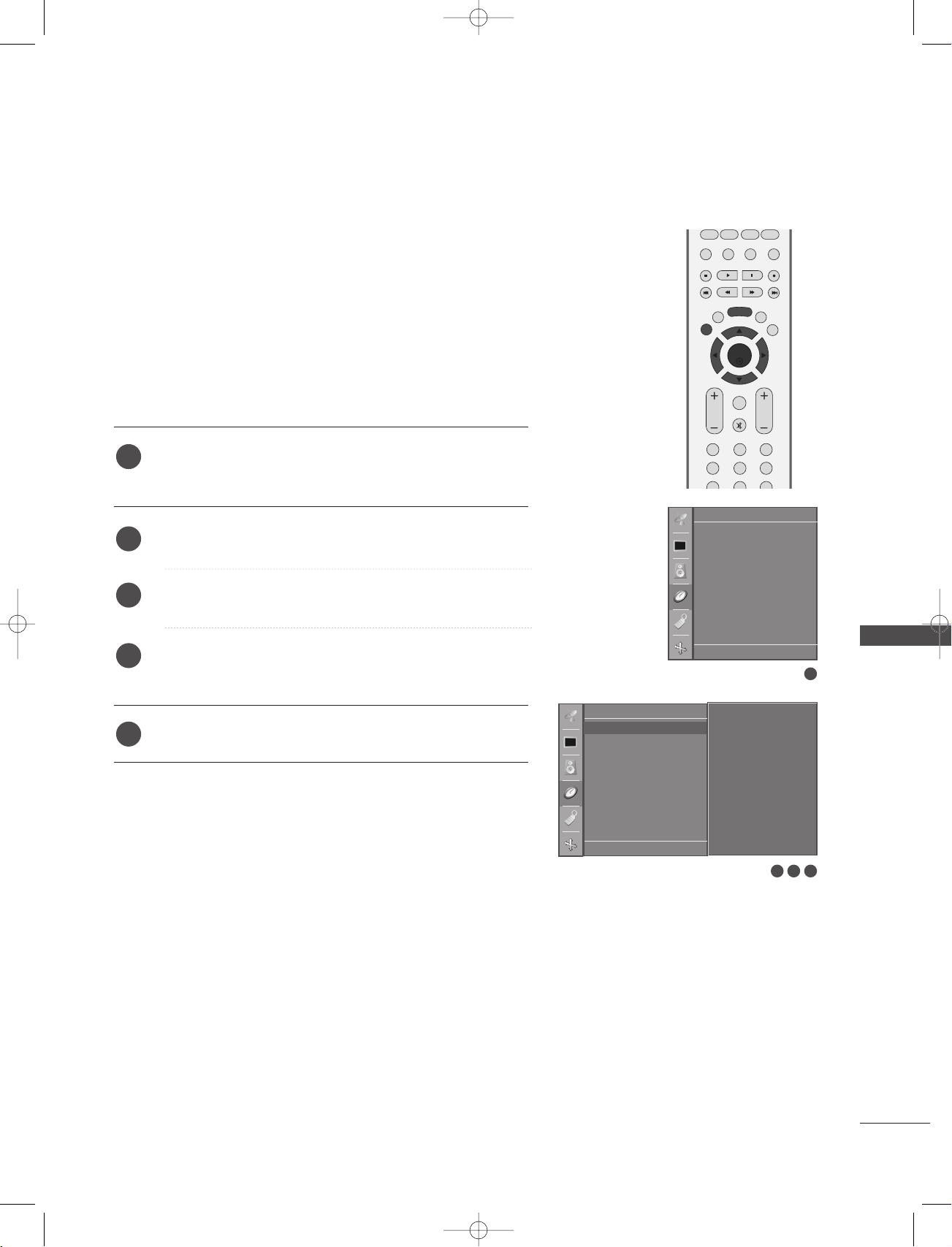
OK
PIP PR- PIP PR+
PIP INPUT
EXIT
VOL
Q.VIEW
MUTE
PR
SLEEP
LIST
I/II
MENU
TEXT PIP SIZE
POSTION
123
456
1-0323E_en_2-rev01 9/29/06 1:49 PM Page 59
TV MENU
Time Menu Options
CLOCK SETUP
You must set the time correctly before using on/off time function.
If current time setting is erased by a power failure or the set is
unplugged, reset the clock.
1
2
Press the
select the
Press the
MM EENNUU
button and then
Time menu.
button and then
GG
DD
DD
EE
//
button to
EE
//
button to select Clock.
Time
Clock
Off time
On time
Auto sleep
3
4
5
Press the
Press the
minutes.
Press the
button and then
GG
button and then
GG
EEXXIITT
button to return to normal TV viewing.
DD
button to set the hour.
EE
//
DD
button to set the
EE
//
Time
Clock G
Off time
On time
Auto sleep
DE F G
OK MENU
DE F G
- - : - -
OK MENU
2 3
TV MENU
1
4
59

OK
PIP PR- PIP PR+
PIP INPUT
EXIT
VOL
Q.VIEW
MUTE
PR
SLEEP
LIST
I/II
MENU
TEXT PIP SIZE
POSTION
123
456
1-0323E_en_2-rev01 9/29/06 1:49 PM Page 60
TV MENU
Time Menu Options
ON/OFF TIME
The Off time automatically switches the set to standby at the
preset time.
Two hours after the set is switched on by the on time function it
will automatically switch back to standby mode unless a button
has been pressed.
Once the on time/off time is set, these functions operate daily at
the preset time.
Off time function overrides On timer function if they are set both
to the same time.
The set must be in standby mode for the On timer to work.
1
Press the
select the
MM EENNUU
button and then
Time menu.
//
EE
button to
DD
Time
Clock
Off time
On time
Auto sleep
TV MENU
2
Press the
button and then
GG
Off time/On time.
3
4
5
Press the
• To cancel
Press the
Press the
button and then
GG
On/Off timer function, select Off.
button and then
GG
button and then
GG
minutes.
FFoorr oonnllyy OOnn ttiimmeerr ffuunnccttiioonn
6
PPrrooggrr aammmmee
•
: Press the
ton to select the programme.
VV oolluummee
•
: Press the
to adjust volume level at turn-on.
7
Press the
EEXX II TT
button to return to normal TV viewing.
//
DD
//
DD
EE
//
DD
EE
//
DD
button and then
GG
button and then
GG
EE
button to select
button to select On.
button to set the hour.
EE
button to set the
//
DD
EE
but-
//
DD
EE
button
Time
Clock
Off time G
On time
Auto sleep
DE F G
Clock
Off time
On time G
Auto sleep
DE F G
OK MENU
Time
OK MENU
DE F G
OK MENU
- - : - -
Off
07:00
PR 1
Vol. 8
On
1
2 3
4 5 6
60

OK
EXIT
VOL
Q.VIEW
PR
SLEEP
LIST
I/II
MENU
!
1-0323E_en_2-rev01 9/29/06 1:49 PM Page 61
AUTO SLEEP
If set to on and there is no input signal, the TV turns off automatically after 10 minutes.
Time
Clock
Off time
On time
Auto sleep
1
2
3
4
Press the
the
Press the
Press the
Press the
MMEENNUU
Time menu.
GG
button and then
GG
button and then
EEXX II TT
button and then
DD
EE
//
DD
EE
//
DD
button to select Auto sleep.
button to select On or Off..
button to select
EE
//
button to return to normal TV viewing.
SLEEP TIMER
You don’t have to remember to switch the set off before you go
to sleep. The sleep timer automatically switches the set to standby after the preset time has elapsed.
Time
Clock
Off time
On time
Auto sleep G
DE F G
OK MENU
DE F G
On
Off
OK MENU
1
2 3
TV MENU
1
Press the
SSLLEEEEPP
button repeatedly to select the number of minutes. The display ‘
-- -- --
’ will
appear on the screen, followed by 10, 20, 30, 60, 90, 120, 180 and 240.
When the number of minutes you want is displayed on the screen, the timer begins to count down
2
from the number of minutes selected.
NOTE
To view the remaining sleep time, press the
GG
To cancel the sleep time, repeatedly press the
GG
When you switch the set off, the set releases the preset sleep time.
GG
SSLLEEEEPP
SSLLEEEEPP
button once.
button until the display ‘
-- -- --
’ appears.
61

OK
PIP PR- PIP PR+
PIP INPUT
EXIT
VOL
Q.VIEW
MUTE
PR
SLEEP
LIST
I/II
MENU
TEXT PIP SIZE
POSTION
123
456
!
1-0323E_en_2-rev01 9/29/06 1:49 PM Page 62
TV MENU
CHILD LOCK
The TV can be set so that the remote control is needed to control it.
This feature can be used to prevent unauthorized viewing.
This set is programmed to remember which option it was last
set to even if you turn the set off.
Press the
1
the
Press the
2
Child lock.
Press the
3
On or Off.
TV MENU
Press the
4
MM EENNUU
Special menu.
GG
button and then
GG
button and then
EEXX II TT
button to return to normal TV viewing.
Special Menu Options
button and then
DD
//
//
DD
DD
EE
EE
button to select
EE
//
button to select
button to select
SPECIAL
Language
Country
Child lock
ISM Method
Low Power
Set ID
Demo
SPECIAL
Language
Country
Child lock
ISM Method
Low Power
Set ID
Demo
DE F G
On
Off
OK MENU
1
62
NOTE
CChhiilldd lloocckk‘OOnn
In
GG
PPOOWWEERR, IINNPPUUTT, TTVV, PPRR
With the
GG
CChhiill dd lloocc kk OO nn
front panel is pressed while viewing the set.
’, if the set is turned off, press the
or NUMBER buttons on the remote control.
++//--
, the display ‘
rr // II,IINNPPUUTT, PPRR DD//
Child lock on
DE F G
OK MENU
EE
button on the set or
’ appears on the screen if any button on the
2 3

OK
PIP PR- PIP PR+
PIP INPUT
EXIT
VOL
Q.VIEW
MUTE
PR
SLEEP
LIST
I/II
MENU
TEXT PIP SIZE
POSTION
123
456
1-0323E_en_2-rev01 9/29/06 1:49 PM Page 63
ISM (Image Sticking Minimization) METHOD
A frozen of still picture from a PC/video game displayed on the
screen for prolonged periods will result in a ghost image remaining
even when you change the image. Avoid allowing a fixed image to
remain on the set's screen for a long period of time.
It’s not available to use this function in LCD models.
WWhhii ttee wwaasshh
White wash removes permanent images from the screen.
NNoottee ::
clear entirely with White Wash.
An excessive permanent image may be impossible to
OOrrbbiitteerr
Orbiter may help prevent ghost images. However, it is best
not to allow any fixed image to remain on the screen. To
avoid a permanent image on the screen, the screen will move
every 2 minutes.
IInnvveerr ssiioonn
This is the function to invert the panel color of the screen.
The panel color is automatically inverted every 30 minutes.
1
2
Press the
select the
Press the
MM EENNUU
button and then
Special menu.
GG
button and then
DD
DD
EE
//
button to
EE
//
button to select
ISM Method.
GG
3
Press the
either
button and then
DD
Normal, White wash, Orbiter or Inversion.
If you unnecessary to set this function, set
button to select
EE
//
Normal.
Special
Language
Country
Child lock
ISM Method G
Low Power
Set ID
Demo
DE F G
OK MENU
SPECIAL
Language
Country
Child lock
ISM Method
Low Power
Set ID
Demo
DE F G
Normal
White wash
Orbiter
Inversion
TV MENU
OK MENU
1
2 3
4
Press the
EEXXIITT
button to return to TV viewing.
63

OK
PIP PR- PIP PR+
PIP INPUT
EXIT
VOL
Q.VIEW
MUTE
PR
SLEEP
LIST
I/II
MENU
TEXT PIP SIZE
POSTION
123
456
1-0323E_en_2-rev01 9/29/06 1:49 PM Page 64
TV MENU
LOW POWER
This is the function to reduce the power consumption of the set.
It’s not available to use this function in LCD models.
1
2
3
TV MENU
4
Press the
select the
Press the
MM EENNUU
Special menu.
GG
Low power.
Press the
GG
On or Off.
Press the
EEXXIITT
Special Menu Options
button and then
button and then
button and then
button to return to TV viewing.
DD
//
DD
DD
button to select
EE
//
//
EE
button to select
button to
EE
Special
Language
Country
Child lock
ISM Method
Low Power G
Set ID
Demo
SPECIAL
Language
Country
Child lock
ISM Method
Low Power
Set ID
Demo
DE F G
On
Off
OK MENU
1
64
DE F G
OK MENU
2 3

OK
PIP PR- PIP PR+
PIP INPUT
EXIT
VOL
Q.VIEW
MUTE
PR
SLEEP
LIST
I/II
MENU
TEXT PIP SIZE
POSTION
123
456
1-0323E_en_2-rev01 9/29/06 1:49 PM Page 65
XD DEMO
Use it to see the difference between XD Demo on and XD
Demo off.
It’s not available to use this function in RGB[PC] mode.
1
2
3
4
Press the
select the
Press the
XXDD DDee mmoo
Press the
To stop
XXDD DDee mmoo
MM EENNUU
button and then use
Special menu.
GG
button and then use
.
GG
button to begin
, press the
DD
//
XXDD DDee mmoo
MM EENNUU
DD
EE
button to
EE
//
button to select
.
button.
Special
Language
Country
Child lock
ISM Method
Low Power
Set ID
Demo G
DE F G
OK MENU
SPECIAL
Language
Country
Child lock
ISM Method
Low Power
Set ID
Demo
DE F G
To start
OK MENU
1
TV MENU
2 3
• XD Demo
XD™Off XD™On
Exit
Menu
65

OK
PIP PR- PIP PR+
PIP INPUT
EXIT
VOL
Q.VIEW
MUTE
PR
SLEEP
LIST
I/II
MENU
TEXT PIP SIZE
POSTION
123
456
1-0323E_en_2-rev01 9/29/06 1:49 PM Page 66
TV MENU
Screen Menu Options
AUTO CONFIGURE (RGB [PC] mode only)
Automatically adjusts picture position and minimizes image
shaking.
After adjustment, if the image is still not correct, your set is
functioning properly but needs further adjustment.
AAuuttoo ccoonnffiigg uurree
This function is for the automatic adjustment of the screen position, clock, and phase. The displayed image will unstable for a few
seconds while the auto configuration is in progress.
1
Press the
select the
MM EENNUU
button and then use
Screen menu.
//
EE
button to
DD
Screen
Auto config.
Manual config.
VGA Mode
ARC
Reset
TV MENU
Press the
2
select
Press the GGbutton to start Auto config..
3
GG
button and then use
Auto config..
//
EE
button to
DD
• When Auto config..has finished, OK will be shown on
screen.
• If the position of the image is still not correct, try
Auto adjustment again.
• If picture needs to be adjusted more after Auto adjust-
Manual
4
ment in RGB (PC), you can adjust the
config
Press the
..
.
EEXXIITT
button to return to TV viewing.
Screen
Auto config. G
Manual config.
VGA Mode
ARC
Reset
DE F G
OK MENU
DE F G
To set
OK MENU
1
2 3
66

OK
PIP PR- PIP PR+
PIP INPUT
EXIT
VOL
Q.VIEW
MUTE
PR
SLEEP
LIST
I/II
MENU
TEXT PIP SIZE
POSTION
123
456
1-0323E_en_2-rev01 9/29/06 1:49 PM Page 67
MANUAL CONFIGURE
If the picture isn’t clear after auto adjustment and especially
if characters are still trembling, adjust the picture phase
manually.
To correct the screen size, adjust
CClloocckk
.
This function works in the following mode : RGB[PC],
RGB[DTV], COMPONENT (480p/576p/720p/1080i), HDMI
(480p/576p/720p/1080i).
It’s not available to use Phase, Clock function in RGB[DTV],
COMPONENT (480p/576p/720p/1080i), HDMI
(480p/576p/720p/1080i).
CClloocckk
This function is to minimize any vertical bars or stripes
visible on the screen background. And the horizontal
screen size will also change.
PPhhaassee
This function allows you to remove any horizontal noise
and clear or sharpen the image of characters.
1
2
Press the
select the
Press the
MM EENNUU
button and then use
Screen menu.
button and then
GG
//
EE
button to
DD
DD
button to select
EE
//
Manual config..
Screen
Auto config.
Manual config. G
VGA Mode
ARC
Reset
Screen
Auto config.
Manual config.
VGA Mode
ARC
Reset
DE F G
OK MENU
Phase 50
Clock + 10
H-Position 0
V-Position 0
TV MENU
1
Press the GGbutton and then
3
DD
Phase, Clock, H-Position or V-Position.
4
Press the
FF
button to make appropriate
GG
//
adjustments.
5
Press the
EEXXIITT
button to return to TV viewing.
button to select
EE
//
DE F G
OK MENU
2 3 4
67
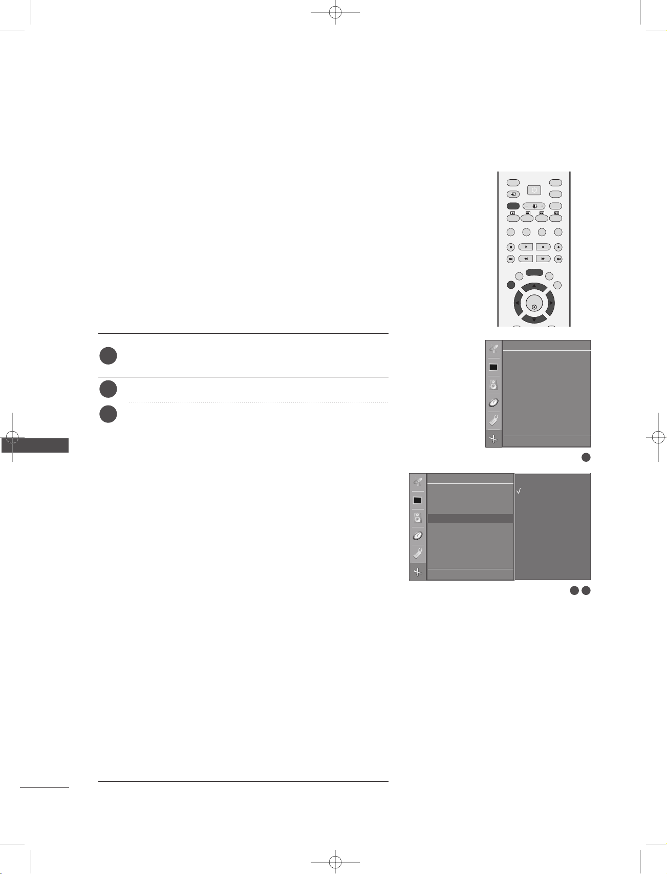
OK
INPUT
TVTV
INPUT
PIP PR- PIP PR+
PIP INPUT
DVD
ARC
EXIT
SLEEP
LIST
I/II
MENU
TEXT PIP SIZE
POSTION
VCR
POWER
1-0323E_en_2-rev01 9/29/06 1:49 PM Page 68
TV MENU
SETTING THE PICTURE FORMAT
TV MENU
You can watch the screen in various picture formats;
OOrriiggiinnaall, 44::33, 1166 ::99, 1144 ::99
and
ZZoooomm
.
SSppeeccttaaccllee
,
FF uullll
If a fixed image is displayed on the screen for a long time, that fixed
image may become imprinted on the screen and remain visible.
There might be uncomfortable in full mode. Then change into other
mode.
You can adjust the enlarge proportion using
DD
//
button.
EE
This function works in the following signal.
1
2
3
Press the
select the
Press the
Press the
MMEE NNUU
button and then use
Screen menu.
GG
button and then use
GG
button and then use
DD
button to select ARC.
DD
EE
//
DD
button to select
EE
//
//
EE
button to
Spectacle, Full, Original, 4:3, 16:9, 14:9, Zoom1 or Zoom2.
SSppeeccttaaccllee
•
When your TV receives the wide screen signal, when
selected it will adjust the picture horizontally, in non-linear
proportion, to fill the entire screen.
FF uullll
•
When your TV receives the wide screen signal, when
selected it will adjust the picture horizontally or vertically,
in a linear proportion, to fill the entire screen fully. (This
feature is not available in NTSC signal.)
,
Screen
Auto config.
Manual config.
VGA Mode
ARC G
Reset
Screen
Auto config.
Manual config.
VGA Mode
ARC
Reset
DE F G
OK MENU
Spectacle
Full
Original
4:3
16:9
14:9
Zoom1
Zoom2
1
68
OOrriiggiinnaall
•
When your TV receives the wide screen signal, it will be
automatically changed to the picture format to be sent.
44::33
•
Following selection will lead you to view a picture with an
original 4:3 aspect ratio, with gray bars appearing at both
the left and right sides.
1166 ::99
•
Following selection will lead you to adjust the picture hor
izontally, in a linear proportion, to fill the entire screen
(useful for viewing 4:3 formatted DVDs).
1144 ::99
•
You can enjoy the picture format of 14:9 or general TV
programme through the 14:9 mode. The screen 14:9 is viewed
just like that the screen 4:3 is magnified to the left / right.
DE F G
OK MENU
2 3

!
OK
PIP PR- PIP PR+
PIP INPUT
EXIT
Q.VIEW
SLEEP
LIST
I/II
MENU
TEXT PIP SIZE
POSTION
1-0323E_en_2-rev01 9/29/06 1:49 PM Page 69
ZZoooomm11
•
Following selection will lead you to view the picture without any
alternation, while filling the entire screen. However, the top and
bottom portions of the picture will be cropped.
ZZoooomm22
•
Choose
ZZoooomm22
when you want the picture to be altered,
both horizontally extended and vertically cropped. The pic
ture taking a halfway trade off between alteration and screen
coverage.
NOTE
You can only select
GG
(Wide) in Component, RGB,
HDMI mode only.
44::33, 1166 ::99
4
Press the
EEXX IITT
button to return to TV viewing.
SELECTING WIDE VGA/XGA MODE
To see a normal picture, match the resolution of RGB mode and
selection of VGA/XGA mode.
This function works in the following mode: RGB[PC] mode.
VGA Mode: 42PC1RV, 42PC3RV
XGA Mode: 26C2R*, 27LC2R*, 32LC2R*, 32LC25R*, 26LC3R*,
32LC3R*, 32LX2R*, 32LE2R*, 37LE2R*, 42LE2R*,
1
42PC3RA
Press the
select the
*
MMEE NNUU
button and then use
Screen menu.
*
//
EE
button to
DD
TV MENU
Screen
Auto config.
Manual config.
VGA Mode
ARC
Reset
GG
2
Press the
button and then use
VGA Mode (or XGA Mode).
GG
3
Press the
button and then use
the desired VGA/XGA resolution.
4
Press the
EEXX IITT
button to return to TV viewing.
DD
DD
button to select
EE
//
button to select
EE
//
Screen
Auto config.
Manual config.
VGA Mode G
ARC
Reset
DE F G
OK MENU
DE F G
640x480
848x480
852x480
OK MENU
1
2 3
69

OK
PIP PR- PIP PR+
PIP INPUT
EXIT
VOL
Q.VIEW
MUTE
PR
SLEEP
LIST
I/II
MENU
TEXT PIP SIZE
POSTION
123
456
1-0323E_en_2-rev01 9/29/06 1:49 PM Page 70
TV MENU
Screen Menu Options
INITIALIZING
(RESET TO ORIGINAL FACTORY SETTINGS)
This function operates in current mode.
To initialize the adjusted value
1
2
Press the
the
Press the
MMEE NNUU
Screen menu.
GG
button and then
button and then
DD
//
DD
EE
Reset.
GG
3
Press the
button.
• You can initialize Position, PIP size, PIP position.
button to select
EE
//
button to select
Screen
Auto config.
Manual config.
VGA Mode
ARC
Reset
TV MENU
Screen
Auto config.
Manual config.
VGA Mode
ARC
Reset G
DE F G
OK MENU
DE F G
To set
OK MENU
1
2 3
70

1-0323E_en_2-rev01 9/29/06 1:49 PM Page 71
APPENDIX
PROGRAMMING THE REMOTE
The remote is a multi-brand or a universal remote. It can be programmed to operate most remote-controllable devices of other manufacturers.
Note that the remote may not control all models of other brands.
Programming a code into a remote mode
Test your remote control.
1
To find out whether your remote control can operate the component without programming, turn on the
component such as a VCR and press the corresponding mode button (such as a
remote control, while pointing at the component. Test the
component responds properly. If not, the remote requires programming to operate the device.
PPOOWWEERR
and
DD VV DD
PPRR ++ // --
VV CCRR
or
buttons to see if the
) on the
Turn on the component to be programmed, then press the corresponding mode button (such as a
2
VV CCRR
) on the remote control. The remote control button of desired device is lighted.
Press the
3
code.
Enter a code number using the number buttons on the remote control. Programming code numbers for the
4
corresponding component can be found on the following pages. Again, if the code is correct, the device will
turn off.
Press the
5
Test the remote control functions to see if the component responds properly. If not, repeat from step 2.
6
MMEE NNUU
MMEE NNUU
MMUUTTEE
and
button to store the code.
buttons simultaneously, the remote control is ready to be programmed for the
Programming code
DVD
Brand Codes Brand Codes Brand Codes
DD VV DD
or
APPENDIX
APEX DIGITAL 022
DENON 020 014
GE 005 006
HARMAN KARDON 027
JVC 012
LG 001 010 016 025
MAGNAVOX 013
MARANTZ 024
MITSUBISHI 002
NAD 023
ONKYO 008 017
PANASONIC 003 009
PHILIPS 013
PIONEER 004 026
PROCEED 021
PROSCAN 005 006
RCA 005 006
SAMSUNG 011 015
SONY 007
THOMPSON 005 006
TOSHIBA 019 008
YAMAHA 009 018
ZENITH 010 016 025
71

1-0323E_en_2-rev01 9/29/06 1:49 PM Page 72
APPENDIX
VCRs
Brand Codes Brand Codes Brand Codes
AIWA 034
AKAI 016 043 046 124
AMPRO 072
ANAM 031 033 103
AUDIO DYNAMICS
BROKSONIC 035 037 129
CANON 028 031 033
CAPEHART 108
CRAIG 003 040 135
CURTIS MATHES 031 033 041
DAEWOO 005 007 010 064
DAYTRON 108
DBX 012 023 039 043
DYNATECH 034 053
ELECTROHOME 059
EMERSON 006 017 025 027
FISHER 003 008 009 010
FUNAI 034
GE 031 033 063 072
APPENDIX
GO VIDEO 132 136
HARMAN KARDON 012 045
HITACHI 004 018 026 034
INSTANTREPLAY 031 033
JCL 031 033
JCPENNY 012 013 015 033
JENSEN 043
JVC 012 031 033 043
KENWOOD 014 034 039 043
LG (GOLDSTAR) 001 012 013 020
LLOYD 034
LXI 003 009 013 014
MAGIN 040
12 5 14 6
012 0 23 0 39 0 43
0 6 5 10 8 110 111
112 116 117 119
029 031 034 035
036 037 046 101
12 9 131 13 8 15 3
10 7 10 9 14 4 14 7
043 063 137 150
040 066 101
048 050 055 060
13 0 15 0 15 2
047 048
101 10 6 114 12 3
017 03 4 101 106
MAGNAVOX 031 033 034 041
067 068
MARANTZ 012 031 033 067
069
MARTA 101
MATSUI 027 030
MEI 031 033
MEMOREX 003 010 014 031
033 034 053 072
101 10 2 134 13 9
MGA 045 046 059
MINOLTA 013 020
MITSUBISHI 013 020 045 046
049 051 059 061
151
MT C 034 040
MULTITECH 024 034
NEC 012 023 039 043
048
NORDMENDE 043
OPTONICA 053 054
PANASONIC 066 070 074 083
13 3 14 0 14 5
PENTAX 013 020 031 033
063
PHILCO 031 034 067
PHILIPS 031 033 034 054
067 071 101
PILOT 101
PIONEER 013 021 048
PORTLAND 108
PULSAR 072
QUARTZ 011 014
QUA SAR 033 066 075 145
RCA 013 020 033 034
040 041 062 063
107 109 140 144
14 5 14 7
REALISTIC 003 008 010 014
031 033 034 040
053 054 101
RICO 058
RUNCO 148
SALORA 014
SAMSUNG 032 040 102 104
10 5 10 7 10 9 112
113 115 12 0 12 2
12 5
SANSUI 022 043 048 135
SANYO 003 007 010 014
10 2 13 4
SCOTT 017 037 112 129
131
SEARS 003 008 009 010
013 014 017 0 20
031 042 073 081
101
SHARP 031 054 149
SHINTOM 024
SONY 003 009 031 052
056 057 058 076
077 078 149
SOUNDESIGN 034
STS 013
SYLVANIA 031 033 034 059
067
SYMPHONIC 034
TANDY 010 034
TATUNG 039 043
TEAC 034 039 043
TECHNICS 031 033 070
TEKNIKA 019 031 033 034
101
THOMAS 034
TMK 006
TOSHIBA 008 013 042 047
059 082 112 131
TOTEVISION 040 101
UNITECH 040
VECTOR RESEARCH
VICTOR 048
VIDEO CONCEPTS
VIDEOSONIC 040
WARDS 003 013 017 024
YAM AH A 012 034 039 043
ZENITH 034 048 056
012
012 03 4 0 46
031 033 034 040
053 054 131
058 072 080 101
72

1-0323E_en_2-rev01 9/29/06 1:49 PM Page 73
TROUBLESHOOTING CHECKLIST
TThhee ooppeerraattiioonn ddooeess nnoott wwoorrkk nnoorrmmaallllyy..
■
Check to see if there is any object between the product and the remote control
causing obstruction.
TThhee rreemmoottee ccoonnttrrooll
ddooeessnn’’tt wwoorrkk
PPoowweerr iiss ssuuddddeennllyy
tt uurrnneedd ooffff
■
Are batteries installed with correct polarity (+ to +, - to -)?
■
Correct remote operating mode set: TV, VCR etc.?
■
Install new batteries.
■
Is the sleep timer set?
■
Check the power control settings. Power interrupted
■
No broadcast on station tuned with Auto off activated.
TThhee vviiddeeoo ffuu nnccttiioonn ddooeess nnoott wwoorrkk..
■
Check whether the product is turned on.
■
Try another channel. The problem may be with the broadcast.
■
NNoo ppiiccttuurree &&
NNoo ssoouunndd
Is the power cord inserted into wall power outlet?
■
Check your antenna direction and/or location.
■
Test the wall power outlet, plug another product’s power cord into the outlet
where the product’s power cord was plugged in.
■
PPiiccttuurree aappppeeaarrss ssllooww--
llyy aafftteerr ssww iittcchhiinngg oonn
NNoo oorr ppoooorr ccoolloorr
oorr ppoooorr ppii ccttuurree
HHoorriizzoonnttaall//vveerrttiiccaall
This is normal, the image is muted during the product startup process. Please
contact your service center, if the picture has not appeared after five minutes.
■
Adjust Color in menu option.
■
Keep a sufficient distance between the product and the VCR.
■
Try another channel. The problem may be with the broadcast.
■
Are the video cables installed properly?
■
Activate any function to restore the brightness of the picture.
■
Check for local interference such as an electrical appliance or power tool.
bbaarrss oorr ppiiccttuurree sshhaakkiinngg
APPENDIX
PPoooorr rreecceeppttiioonn oonn
ssoommee cchh aannnneellss
LLii nneess oorr ssttrreeaakkss iinn
ppii ccttuurreess
■
Station or cable product experiencing problems, tune to another station.
■
Station signal is weak, reorient antenna to receive weaker station.
■
Check for sources of possible interference.
■
Check antenna (Change the direction of the antenna).
73

1-0323E_en_2-rev01 9/29/06 1:49 PM Page 74
APPENDIX
TROUBLESHOOTING CHECKLIST
TThhee aauuddiioo ffuunnccttiioonn ddooeess nnoott wwoorr kk..
PPiiccttuurree OOKK &&
NNoo ssoouunndd
NNoo oouuttppuutt ffrroomm oonnee
ooff tthhee ssppeeaakkeerrss
UUnnuussuuaall ssoouunndd ffrroomm
iinnssiiddee tthhee pprroodduucctt
■
Press the
■
Sound muted? Press
■
Try another channel. The problem may be with the broadcast.
■
Are the audio cables installed properly?
■
Adjust Balance in menu option.
■
A change in ambient humidity or temperature may result in an unusual noise
when the product is turned on or off and does not indicate a fault with the
product.
VVOOLL++//-- ((oorr VV oolluummee))
MMUUTTEE
button.
TThheerree iiss aa pprroobbllee mm iinn PPCC mmooddee.. ((OOnnllyy PPCC mmooddee aapppplliieedd))
■
TThhee ssiiggnnaall iiss oouutt ooff
rraannggee..
Adjust resolution, horizontal frequency, or vertical frequency.
■
Check the input source.
button.
APPENDIX
ggrroouunndd && HHoorr iizzoonnttaall
NNooiissee && IInnccoorrrreecctt
uunnssttaabbllee oorr ssiinn ggllee
VV eerrttiiccaall bbaarr oorr
ssttrr iippee oonn bbaacckk--
ppoossiittiioonn
SSccrreeeenn ccoolloouurr iiss
ccooll oo uurr
■
Work the Auto configure or adjust clock, phase, or H/V position.
■
Check the signal cable.
■
Reinstall the PC video card.
74

1-0323E_en_2-rev01 9/29/06 1:49 PM Page 75
MAINTENANCE
Early malfunctions can be prevented. Careful and regular cleaning can extend the amount of time you will
have your new TV. Be sure to turn the power off and unplug the power cord before you begin any cleaning.
Cleaning the Screen
Here’s a great way to keep the dust off your screen for a while. Wet a soft cloth in a mixture of lukewarm
1
water and a little fabric softener or dish washing detergent. Wring the cloth until it’s almost dry, and then
use it to wipe the screen.
Make sure the excess water is off the screen, and then let it air-dry before you turn on your TV.
2
Cleaning the Cabinet
■
To remove dirt or dust, wipe the cabinet with a soft, dry, lint-free cloth.
■
Please be sure not to use a wet cloth.
Extended Absence
CAUTION
If you expect to leave your TV dormant for a long time (such as a vacation), it’s a good idea to unplug
the power cord to protect against possible damage from lightning or power surges.
APPENDIX
75

1-0323E_en_2-rev01 9/29/06 1:49 PM Page 76
APPENDIX
PRODUCT SPECIFICATIONS
MODELS
Dimensions
(Width x Height x Depth)
Weight
Power requirement
Power Consumption
Television System
Program Coverage
External Antenna Impedance
Environment condition
with stand
without stand
with stand
without stand
Operating Temperature
Operating Humidity
Storage Temperature
Storage Humidity
26LC2R
26LC2R-ZJ
26LC2RB-ZJ
26LC2RA-ZJ
681.0 x 542.0 x 172.0 mm
26.8 x 21.3 x 6.8 inches
681.0 x 490.8 x 119.0 mm
26.8 x 19.3 x 4.6 inches
18.5 kg / 40.8 lbs
15.2 kg / 33.5 lbs
AC100-240V~50/60Hz 1.3A
130 W
VHF: E2
*
PAL/SECAM B/G/D/K, PAL I/II, SECAM L/L’
~ E12, UHF: E21 ~ E69, CATV: S1 ~ S20, HYPER: S21 ~ S47
26LC3R
26LC3R-ZJ
680.0 x 550.0 x 235.0 mm
26.8 x 21.7 x 9.3 inches
680.0x 436.6 x 119.4 mm
26.8 x 17.2 x 4.7 inches
12.4 kg / 27.3 lbs
11.5 kg / 25.3 lbs
AC100-240V~50/60Hz 1.3A
130 W
0 ~ 40°C / 32 ~ 104°F
Less than 80%
-20 ~ 60°C / -4 ~ 140°F
Less than 85%
*
75 Ω
27LC2R
27LC2R-ZJ
686.0 x 550.0 x 235.0 mm
27.0 x 21.7 x 9.3 inches
686.0 x 493.5 x 119.4 mm
27.0 x 19.4 x 4.7 inches
14.5 kg / 32.0 lbs
11.4 kg / 25.1 lbs
AC100-240V~50/60Hz 1.3A
130 W
*
APPENDIX
76
■
The specifications shown above may be changed without prior notice for quality improvement.

1-0323E_en_2-rev01 9/29/06 1:49 PM Page 77
PRODUCT SPECIFICATIONS
MODELS
Dimensions
(Width x Height x Depth)
Weight
Power requirement
Power Consumption
Television System
Program Coverage
External Antenna Impedance
Environment condition
with stand
without stand
with stand
without stand
Operating Temperature
Operating Humidity
Storage Temperature
Storage Humidity
32LC2R
32LC2R-ZJ
32LC2RB-ZJ
32LC2RA-ZJ
811.0 x 630.0 x 235.0 mm
31.9 x 24.8 x 9.3 inches
811.0 x 566.8 x 123.5 mm
31.9 x 22.3 x 4.9 inches
21.9 kg / 48.2 lbs
18.5 kg / 40.8 lbs
AC100-240V~50/60Hz 1.5A
150 W
VHF: E2
32LC25R
*
32LC25R-ZJ
PAL/SECAM B/G/D/K, PAL I/II, SECAM L/L’
~ E12, UHF: E21 ~ E69, CATV: S1 ~ S20, HYPER: S21 ~ S47
*
32LC3R
32LC3R-ZJ
935.0 x 570.0 x 244.0 mm
36.8 x 22.4 x 9.6 inches
923.0 x 522.0 x 124.0 mm
36.4 x 20.6 x 4.9 inches
19.8 kg / 43.7 lbs
17.9 kg / 39.5 lbs
AC100-240V~50/60Hz 1.5A
150 W
0 ~ 40°C / 32 ~ 104°F
Less than 80%
-20 ~ 60°C / -4 ~ 140°F
Less than 85%
*
75 Ω
32LX2R
32LX2R-ZJ
917.5 x 614.3 x 287.5 mm
36.1 x 24.2 x 11.3 inches
917.5 x 522.0 x 124.0 mm
36.1 x 20.6 x 4.9 inches
25.2 kg / 55.6 lbs
17.9 kg / 39.5 lbs
AC100-240V~50/60Hz 2.0A
140 W
*
■
The specifications shown above may be changed without prior notice for quality improvement.
APPENDIX
77

1-0323E_en_2-rev01 9/29/06 1:49 PM Page 78
APPENDIX
PRODUCT SPECIFICATIONS
Dimensions
(Width x Height x Depth)
Weight
Power requirement
Power Consumption
Television System
Program Coverage
External Antenna Impedance
Environment condition
APPENDIX
MODELS
with stand
without stand
with stand
without stand
Operating Temperature
Operating Humidity
Storage Temperature
Storage Humidity
32LE2R
*
32LE2R-ZJ
811.0 x 630.0 x 235.0 mm
31.9 x 24.8 x 9.3 inches
811.0 x 566.8 x 123.5 mm
31.9 x 22.3 x 4.9 inches
21.9 kg / 48.2 lbs
18.5 kg / 40.8 lbs
AC100-240V~50/60Hz 1.5A
150 W
PAL/SECAM B/G/D/K, PAL I/II, SECAM L/L’
VHF: E2
~ E12, UHF: E21 ~ E69, CATV: S1 ~ S20, HYPER: S21 ~ S47
37LE2R
37LE2R-ZJ
943.9 x 286.0 x 734.6 mm
37.2 x 11.3 x 28.9 inches
943.9 x 152.2 x 695.5 mm
37.2 x 6.0 x 27.4 inches
28.6 kg/63.0 lbs
24.0 kg /52.9 lbs
AC100-240V~50/60Hz 2.0A
190 W
75 Ω
0 ~ 40°C / 32 ~ 104°F
Less than 80%
-20 ~ 60°C / -4 ~ 140°F
Less than 85%
*
42LE2R
*
42LE2R-ZJ
1054.0 x 813.5 x286.0 mm
41.5 x 32.0x 11.2 inches
1054.0 x 746.0 x 136.8mm
41.5 x 29.3 x 5.3 inches
36.9kg/81.3 lbs
31.3kg/69.0 lbs
AC100-240V~50/60Hz 2.5A
240W
78
■
The specifications shown above may be changed without prior notice for quality improvement.
1-0323E_en_2-rev01 9/29/06 1:49 PM Page 79
PRODUCT SPECIFICATIONS
MODELS
Dimensions
(Width x Height x Depth)
Weight
Power requirement
Power Consumption
Television System
Program Coverage
External Antenna Impedance
Environment condition
with stand
without stand
with stand
without stand
Operating Temperature
Operating Humidity
Storage Temperature
Storage Humidity
42PC1RV
42PC1RV-ZJ
42PC1RVA-ZJ
1129.0 x 748.5 x 380.0 mm
44.4 x 29.5 x 15.0 inches
1129.0 x 695.0 x 103.7 mm
44.4 x 27.4 x 4.1 inches
27.7 kg / 61.1 lbs
24.2 kg / 53.4 lbs
AC100-240V~ 50/60Hz 3.0A
260 W
VHF: E2
*
PAL/SECAM B/G/D/K, PAL I/II, SECAM L/L’
~ E12, UHF: E21 ~ E69, CATV: S1 ~ S20, HYPER: S21 ~ S47
42PC3RV
42PC3RV-ZJ
1129.0 x 748.5 x 333.6 mm
44.4 x 29.5 x 13.1 inches
1129.0 x 695.0 x 103.7 mm
44.4 x 27.4 x 4.1 inches
31.5 kg / 69.4 lbs
24.2 kg / 53.3 lbs
AC100-240V~ 50/60Hz 3.0A
260 W
0 ~ 40°C / 32 ~ 104°F
Less than 80%
-20 ~ 60°C / -4 ~ 140°F
Less than 85%
*
75 Ω
42PC3RA
42PC3RA-ZJ
1129.0 x 748.5 x 333.6 mm
44.4 x 29.5 x 13.1 inches
1129.0 x 695.0 x 103.7 mm
44.4 x 27.4 x 4.1 inches
31.5 kg / 69.4 lbs
24.2 kg / 53.3 lbs
AC100-240V~ 50/60Hz 3.5A
310W
*
APPENDIX
■
The specifications shown above may be changed without prior notice for quality improvement.
79

REMOTE
CONTROL IN
AUDIO IN
(RGB)
RGB IN
(PC/DTV)
AUDIO OUT
VARIABLE
HDMI IN
RS-232C INRS-232C IN
(CONTR(CONTROLOL
&
SERSERVICE)VICE)
RGB IN
(PC/DTV)
AUDIO OUT
VARIABLE
HDMI IN
RS-232C IN
(CONTROL
&
SERVICE)
1-0323E_en_3-rev01 9/29/06 1:52 PM Page 80
APPENDIX
EXTERNAL CONTROL DEVICE SETUP
Connect the RS-232C input jack to an external control device (such as a computer or an A/V control
system) and control the TV’s functions externally.
Connect the serial port of the control device to the RS-232C jack on the TV back panel.RS-232C connection cables are not supplied with the TV.
RS-232C Setup
Type of Connector; D-Sub 9-Pin Male
APPENDIX
No. Pin Name
1 No connection
2 RXD (Receive data
3 TXD (Transmit data
4 DTR (DTE side ready
5 GND
6 DSR (DCE side ready
7RTS
(
Ready to send
8 CTS (Clear to send
9 No Connection
1
6
)
)
)
)
)
)
5
99
80

OK
EXIT
VOL
Q.VIEW
PR
SLEEP
LIST
I/II
MENU
1-0323E_en_3-rev01 9/29/06 1:52 PM Page 81
RS-232C Configurations
7-Wire Configurations (Standard RS-232C cable
PC TV SET
RXD 2 3 TXD
TXD 3 2 RXD
GND 5 5 GND
DTR 4 6 DSR
DSR 6 4 DTR
RTS 7 8 CTS
CTS 8 7 RTS
D-Sub 9 D-Sub 9
Set ID
- Use this function to specify a set ID number.
- Refer to ‘Real Data Mapping 1’. See page 85.
)
3-Wire Configurations(Not standard
)
PC TV SET
RXD 2 3 TXD
TXD 3 2 RXD
GND 5 5 GND
DTR 4 6 DTR
DSR 6 4 DSR
RTS 7 7 RTS
CTS 8 8 CTS
D-Sub 9 D-Sub 9
Press the
1
to select the
2
Press the
Press the
3
adjust
MM EENNUU
button and then
Special menu.
button and then use
GG
button and then use
GG
DD//EE
Set ID to choose the desired monitor ID number.
• The adjustment range of
4
Press the
EEXXIITT
button to return to normal TV viewing.
Communication Parameters
■
Baud rate : 9600 bps (UART
■
Data length : 8 bits
■
Parity : None
)
//
button
EE
DD
button to select Set ID.
button to
FF
GG
//
Set ID is 1 ~ 99.
■
Stop bit : 1 bit
■
Communication code : ASCII code
■
Use a crossed (reverse) cable.
Language
Child lock
ISM Method
Low Power
Set ID
Demo
APPENDIX
G
1
81

1-0323E_en_3-rev01 9/29/06 1:52 PM Page 82
APPENDIX
Command Reference List
CCOO MM MM AANNDD11 CCOOMM MM AANNDD22
01. Power k a 0 ~ 1
02. Aspect Ratio k c *
03. Screen Mute k d 0 ~ 1
04. Volume Mute k e 0 ~ 1
05. Volume Control k f 0 ~ 64
06. Contrast k g 0 ~ 64
07. Brightness k h 0 ~ 64
08. Colour k i 0 ~ 64
09. Tint k j 0 ~ 64
10. Sharpness k k 0 ~ 64
11. OSD Select k l 0 ~ 1
12. Remote Control 0 ~ 1
lock mode
13. PIP/DW k n *
14. PIP Position k q 0 ~ 3
k m
DATA
(Hexadecimal)
CCOO MM MM AANNDD11 CCOOMM MM AANNDD22
15. Balance k t 0 ~ 64
16. Colour Temperature k u 0 ~ 3
17. Red Adjustment k v 0 ~ 3C
18. Green Adjustment k w 0 ~ 3C
19. Blue Adjustment k $ 0 ~ 3C
Abnormal Status
20.
21. ISM Method j p 0 ~ 3
22. Low Powe r j q 0 ~ 1
23. Orbiter Time Setting j r 1 ~ FE
24. Orbiter Pixel Setting j s 1 ~ 3
25. Auto Configure j u 1
Tune Command
26.
27. Key m c Key Code
28. Input select (Main) x b
29. Input select (PIP) x y
k z FF
m a *
DATA
(Hexadecimal)
*
*
Transmission / Receiving Protocol
APPENDIX
TTrraannssmm iissss iioonn
[[CCoommmmaanndd11]][[CCoomm mmaa nndd22]][[ ]] [[SSeett IIDD]][[ ]][[ DDaattaa]][[CCrr]]
[Command 1] : First command to control the set.(j,k,mor x)
[Command 2] : Second command to control the set.
[Set ID] : You can adjust the seIDtochoosedesired TV ID
[DATA] : To transmit command data.
[Cr] : Carriage Return
[ ] : ASCII code ‘space (0x20)’
number in Setup menu. Adjustment range is 1
When selecting Set ID ‘0’, every connected the TV
is controlled. Set ID is indicated as decimal (1
99)on menu and as Hexa decimal (0x0~ 0x63
on transmission/receiving protocol.
Transmit ‘FF’ data to read status of comand.
ASCII code ‘0x0D’
~ 99.
~
)
OOKK AAcckknnoowwlleedd ggeemmeenntt
[[CCoommmmaanndd22]][[ ]] [[SSeett IIDD ]][[ ]][[OOKK]][[DDaattaa ]][[xx]]
The TV transmits ACK (acknowledgement) based on this format when receiving normal data. At this time, if the data is
data read mode, it indicates present status data. If the data is
data write mode, it returns the data of the PC computer.
EErr rroorr AAcckk nnoowwlleeddggeemmeenntt
[[CCoommmmaanndd22]][[ ]] [[SSeett IIDD ]][[ ]][[NNGG]][[DDaa ttaa ]][[xx]]
The TV transmits ACK (acknowledgement) based on this format when receiving abnormal data from non-viable functions
or communication errors.
Data1: Illegal Code
Data2: Not supported function
Data3: Wait more time
82

1-0323E_en_3-rev01 9/29/06 1:52 PM Page 83
0011.. PPoowweerr ((CCoommmmaanndd22::aa))
To control Power On/Off of the TV.
Transmission [k][a][ ][Set ID][ ][Data][Cr]
Data 0 : Power Off Data 1 : Power On
Acknowledgement [a][ ][Set ID][ ][OK][Data][x]
To show Power On/Off.
Transmission [k][a][ ][Set ID][ ][FF][Cr]
Acknowledgement [a][ ][Set ID][ ][OK][Data][x]
* In a like manner, if other functions transmit ‘FF’
data based on this format, Acknowledgement data
feedback presents status about each function.
* To change the Power on input the transmission
more than twice.
0022.. AAssppeecctt RRaattiioo ((CCoommmmaanndd22::cc)) ((MMaaiinn ppiiccttuurree ssiizzee))
To adjust the screen format. (Main picture format)
You can also adjust the screen format using the ARC
(Aspect Ratio Control) button on remote control or
in the SCREEN menu.
Transmission [k][c][ ][Set ID][ ][Data][Cr]
Data 1: Normal screen (4:3)
Data 2: Wide screen (16:9)
Data 3: Spectacle
Data 4: Full screen (Zoom1)
Data 5: Full screen (Zoom2)
Data 6: Original
Data 7: Wide screen (14:9)
Data 8: Full (Option)
0055.. VVoolluummee CCoonnttrrooll ((CCoommmmaanndd22::ff))
To adjust volume.
You can also adjust volume with the volume buttons
on remote control.
Transmission [k][f][ ][Set ID][ ][Data][Cr]
Data Min : 0 ~ Max : 64
Refer to ‘Real data mapping 1 ’. See page 85.
Acknowledgement [f][ ][Set ID][ ][OK][Data][x]
0066.. CCoonnttrraasstt ((CCoommmmaanndd22::gg))
To adjust screen contrast.
You can also adjust contrast in the PICTURE menu.
Transmission [k][g][ ][Set ID][ ][Data][Cr]
Data Min : 0 ~ Max : 64
Refer to ‘Real data mapping 1’. See page 85.
Acknowledgement [g][ ][Set ID][ ][OK][Data][x]
0077.. BBrriigghhttnneessss ((CCoommmmaanndd22::hh))
To adjust screen brightness.
You can also adjust brightness in the PICTURE menu.
Transmission [k][h][ ][Set ID][ ][Data][Cr]
Data Min : 0 ~ Max : 64
Refer to ‘Real data mapping 1’. See page 85.
Acknowledgement [h][ ][Set ID][ ][OK][Data][x]
Acknowledgement [c][ ][Set ID][ ][OK][Data][x]
* Using the RGB-PC or Component input, you select
either 16:9 or 4:3 screen aspect ratio.
0033.. SSccrreeeenn MMuuttee ((CCoommmmaanndd22::dd))
To select screen mute on/off.
Transmission [k][d][ ][Set ID][ ][Data][Cr]
Data 0 : Screen mute off (Picture on)
Data 1 : Screen mute on (Picture off)
Acknowledgement [d][ ][Set ID][ ][OK][Data][x]
0044.. VVoolluummee MMuuttee ((CCoommmmaanndd22::ee))
To control volume mute on/off.
You can also adjust mute using the MUTE button on
remote control.
Transmission [k][e][ ][Set ID][ ][Data][Cr]
Data 0 : Volume mute off (Volume on)
Data 1 : Volume mute on (Volume off)
Acknowledgement [e][ ][Set ID][ ][OK][Data][x]
0088.. CCoolloouurr ((CCoommmmaanndd22::ii))
To adjust the screen colour.
You can also adjust colour in the PICTURE menu.
Transmission [k][i][ ][Set ID][ ][Data][Cr]
Data Min : 0 ~ Max : 64
Refer to ‘Real data mapping 1’. See page 85.
Acknowledgement [i][ ][Set ID][ ][OK][Data][x]
0099.. TTiinntt ((CCoommmmaanndd22::jj))
To adjust the screen tint.
You can also adjust tint in the PICTURE menu.
Transmission [k][j][ ][Set ID][ ][Data][Cr]
Data Red : 0 ~ Green : 64
Refer to ‘Real data mapping 1’. See page 85.
Acknowledgement [j][ ][Set ID][ ][OK][Data][x]
APPENDIX
83

1-0323E_en_3-rev01 9/29/06 1:52 PM Page 84
APPENDIX
1100.. SShhaarrppnneessss ((CCoommmmaanndd22::kk))
1111.. OOSSDD SSeelleecctt ((CCoommmmaanndd22::ll))
1122.. RReemmoottee CCoonnttrrooll LLoocckk MMooddee ((CCoommmmaanndd22::mm))
1133.. PPIIPP // DDWW ((CCoommmmaanndd22::nn))
APPENDIX
To adjust the screen sharpness.
You can also adjust sharpness in the PICTURE menu.
Transmission [k][k][ ][Set ID][ ][Data][Cr]
Data Min: 0 ~ Max: 64
Refer to ‘Real data mapping 1’. See page 85.
Acknowledgement [k][ ][Set ID][ ][OK][Data][x]
To select OSD (On Screen Display) on/off when controlling remotely.
Transmission [k][l][ ][Set ID][ ][Data][Cr]
Data 0: OSD off
Data 1: OSD on
Acknowledgement [l][ ][Set ID][ ][OK][Data][x]
To lock the remote control and the front panel
controls on the set.
Transmission [k][m][ ][Set ID][ ][Data][Cr]
Data 0: Lock off Data 1: Lock on
Acknowledgement [m][ ][Set ID][ ][OK][Data][x]
If you’re not using the remote control and front panel
controls on the TV, use this mode. When main power
is on/off, remote control lock is released.
To control the PIP (Picture In picture)/DW.
You can also control the PIP/DW using the PIP but-
ton on the remote control or in the PIP/DW menu.
Transmission [k][n][ ][Set ID][ ][Data][Cr]
Data 0:PIP/DW off Data 1: PIP
Data3: DW2
Acknowledgement [n][ ][Set ID][ ][OK][Data][x]
1155.. BBaallaannccee ((CCoommmmaanndd22::tt))
To adjust balance.
You can also adjust balance in the SOUND menu.
Transmission [k][t][ ][Set ID][ ][Data][Cr]
Data Min: 0 ~ Max: 64
Refer to ‘Real data mapping 1’. See page 85.
Acknowledgement [t][ ][Set ID][ ][OK][Data][x]
1166.. CCoolloorr TTeemmppeerraattuurree ((CCoommmmaanndd22::uu))
To adjust color temperature.
You can also adjust CSM in the PICTURE menu.
Transmission [k][u][ ][Set ID][ ][Data][Cr]
Data 0: Cool 1: Normal 2: Warm 3: User
Acknowledgement [u][ ][Set ID][ ][OK][Data][x]
1177.. RReedd AAddjjuussttmmeenntt ((CCoommmmaanndd22::vv))
To adjust red in colour temperature.
Transmission [k][v][ ][Set ID][ ][Data][Cr]
Data Min: 0 ~ Max: 3C (or 50)
Refer to ‘Real data mapping 2’. See page 85.
Acknowledgement [v][ ][Set ID][ ][OK][Data][x]
1188.. GGrreeeenn AAddjjuussttmmeenntt ((CCoommmmaanndd22::ww))
To adjust red in colour temperature.
Transmission [k][w][ ][Set ID][ ][Data][Cr]
Data Min: 0 ~ Max: 3C (or 50)
Refer to ‘Real data mapping 2’. See page 85.
Acknowledgement [w][ ][Set ID][ ][OK][Data][x]
1199.. BBlluuee AAddjjuussttmmeenntt ((CCoommmmaanndd22::$$))
To adjust red in colour temperature.
Transmission [k][$][ ][Set ID][ ][Data][Cr]
Data Min: 0 ~ Max: 3C (or 50)
Refer to ‘Real data mapping 2’. See page 85.
84
1144.. PPIIPP PPoossiittiioonn ((CCoommmmaanndd22::qq))
To select sub picture position for PIP.
You can also adjust the sub picture position using
POSI-TION button on the remote control or in the
PIP/DW menu.
Transmission [k][q][ ][Set ID][ ][Data][Cr]
Data 0: Right down on screen
Data 1: Left down on screen
Data 2: Left up on screen
Data 3: Right up on screen
Acknowledgement [q][ ][Set ID][ ][OK][Data][x]
Acknowledgement [$][ ][Set ID][ ][OK][Data][x]

1-0323E_en_3-rev01 9/29/06 1:52 PM Page 85
2200.. AAbbnnoorrmmaall SSttaattee ((CCoommmmaanndd22::zz))
To recognize an abnormal state.
This feature is not available for all models.
Transmission [k][z][ ][Set ID][ ][FF][ ][Cr]
Data FF: Read
Acknowledgement [z][ ][Set ID][ ][OK][Data][x]
Data 0: Normal (Power on and signal exist)
Data 1: No signal (Power on)
Data 2: Turn the TV off by remote control
Data 3: Turn the TV off by sleep time function
Data 4: Turn the TV off by RS-232C function
Data 5: 5V down
Data 6: AC down
Data 7: Turn the TV off by Fan Alarm function (option)
Data 8: Turn the TV off by Off time function
Data 9: Turn the TV off by Auto sleep function
* This function is “read only”.
2211.. IISSMM MMeetthhoodd ((CCoommmmaanndd11::jj,, CCoommmmaanndd22::pp))
To control the ISM method. You can also adjust ISM
Method in SPECIAL menu.
This feature is not available for all models.
Transmission [j][p][ ][Set ID][ ][Data][Cr]
Data 0: Normal Mode Data 1: White Wash
Data2: Orbiter Data3: Inversion
Acknowledgement [p][ ][Set ID][ ][OK][Data][x]
2244 .. OOrrbbiitteerr PPiixxeell SSeettttiinngg ((CCoommmmaanndd11::jj,, CCoommmmaanndd22::ss))
To adjust pixel number in orbiter function.
This feature is not available for all models.
Transmission [j][s][ ][Set ID][ ][Data][Cr]
Data Min: 1 ~ Max: 3
Refer to ‘Real data mapping 1’.
Acknowledgement [s][ ][Set ID][ ][OK][Data][x]
2255 .. AAuuttoo CCoonnffiigguurree ((CCoommmmaanndd11::jj,, CCoommmmaanndd22::uu))
To adjust picture position and minimize image
shaking automatically. It works only in RGB (PC)
mode.
Transmission [j][u][ ][Set ID][ ][Data][Cr]
Data 1: To set
Acknowledgement [u][ ][Set ID][ ][OK][Data][x]
2266 .. PPrrooggrraammmmee sseelleeccttiioonn ((CCoommmmaanndd11mm,, CCoommmmaanndd22::aa))
To select a programme for the main picture.
Transmission [m][a][ ][Set ID][ ][Data0][ ][Data1]
[ ][Data2][Cr]
Data 0: Min: 0 ~ Max: 63 (0 ~ C7, 200 Pr is on)
Refer to ‘Real data mapping 1’.
Data 1: Don’t care
Data 2: 0 : Main
1 : Sub
Acknowledgement [a][ ][Set ID][ ][OK][Data0][x]
APPENDIX
2222.. LLooww PPoowweerr ((CCoommmmaanndd11::jj,, CCoommmmaanndd22::qq))
To reduce the power consumption of the monitor.
You can also adjust Low Power in SPECIAL menu.
This feature is not available for all models.
Transmission [j][q][ ][Set ID][ ][Data][ ][Cr]
Data 0: Off Data 1: On
Acknowledgement [q][ ][Set ID][ ][OK][Data][x]
2233.. OOrrbbiitteerr TTiimmee SSeettttiinngg ((CCoommmmaanndd11::jj,, CCoommmmaanndd22::rr))
To adjust orbiter operation time term.
This feature is not available for all models.
Transmission [j][r][ ][Set ID][ ][Data][ ][Cr]
Data Min: 1 ~ Max: FE
Refer to ‘Real data mapping 1’.
Acknowledgement [r][ ][Set ID][ ][OK][Data][x]
RReeaall ddaa ttaa mmaapp ppiinngg 11
**
0 : Step 0
A : Step 10 (Set ID 10)
F : Step 15 (Set ID 15)
10 : Step 16 (Set ID 16)
64 : Step 100
6E : Step 110
73 : Step 115
74 : Step 116
C7: Step 199
FE : Step 254
FF : Step 255
RReeaall ddaa ttaa mmaapp ppiinngg 22
**
0:-40
1:-39
2:-38
28 : 0
4E : +38
4F : +39
50 : +40
85

1-0323E_en_3-rev01 9/29/06 1:52 PM Page 86
APPENDIX
2277.. KKeeyy ((CCoommmmaanndd11::mm,, CCoommmmaanndd22::cc))
To send IR remote key code.
Transmission [m][c][ ][Set ID][ ][Data][Cr]
Data: Key code - Refer to page 88
Acknowledgement [c][ ][Set ID][ ][OK][Data][x]
2288.. IInnppuutt sseelleecctt ((CCoommmmaanndd11::xx,, CCoommmmaanndd22::bb))
((MMaaiinn PPiiccttuurree IInnppuutt))
To select input source for TV
Transmission [x][b][ ][Set ID][ ][Data][Cr]
Data: Structure
MSB LSB
0 0 0 0 0 0 0 0
External Input Input Number
External Input
000
00
00
0
0
0
1
1
1
1
00
1
0
11
00
1
0
1
1
0
1
Data
Analog
AV
S-Video
Component
RGB-DTV
RGB-PC
HDMI (option)
2299.. IInnppuutt sseelleecctt ((CCoommmmaanndd11::xx,, CCoommmmaanndd22::yy))
To adjust input source for sub picture in PIP mode
Transmission [x][y][ ][Set ID][ ][Data][Cr]
Data: Structure
MSB LSB
0 0 0 0 0 0 0 0
External Input Input Number
External Input
000
0
1
11
00
0
1
0
Data
Analog
AV
S-Video (option)
Input Number Data
0000
000
00
00
1
0
1
0
1
1
0
11
00
1
0
Input1
Input2
Input3
Input4
Input5
Input6
Acknowledgement [y][ ][Set ID][ ][OK][Data][x]
APPENDIX
86
Input Number Data
0000
000
00
00
1
0
1
0
1
1
0
11
00
1
0
Input1
Input2
Input3
Input4
Input5
Input6
Acknowledgement [b][ ][Set ID][ ][OK][Data][x]

Low
custom code
Lead
code
High
custom code
Data code
Data code
C0 C1 C2 C3 C4 C5 C6 C7 D0 D1 D2 D3 D4 D5 D6 D7 D0 D1 D2 D3 D4 D5 D6 D7
Repeat code
Tf
4.5 ms
9 ms
2.25 ms
9 ms
0.55 ms
0.56 ms
1.12 ms
Tf Tf
Tf=108ms @455KHz
0.56 ms
2.24 ms
T1
Tc
1-0323E_en_3-rev01 9/29/06 1:52 PM Page 87
IR CODES
1. How to Connect
■
Connect your wired remote control to the Remote Control port on the TV.
2. Remote Control IR Codes
■
Output waveform
Single pulse, modulated with 37.917KHz signal at 455KHz
Carrier frequency
■
Configuration of frame
1st frame
Repeat frame
■
Lead code
■
Repeat code
FCAR = 1/TC = fOSC/12
Duty ratio = T1/TC = 1/3
APPENDIX
■
BB iitt ddeessccrriipptt iioonn
Bit ”0” Bit ”1”
■
FFrraammee iinntteerrvvaall:: TTff
The waveform is transmitted as long as a key is depressed.
87

1-0323E_en_3-rev01 9/29/06 1:52 PM Page 88
APPENDIX
REMOTE CONTROL IR CODES
Code
(Hexa)
0F TV R/C Button
0B INPUT R/C Button
08 POWER R/C Button (Power On/Off)
C4 POWER ON Discrete IR Code (Only Power On)
C5 POWER OFF Discrete IR Code (Only Power OFF)
60 PIP R/C Button
0E SLEEP R/C Button
20 TEXT R/C Button
0A I/II R/C Button
43 MENU R/C Button
79 ARC R/C Button
5B EXIT R/C Button
07
06
40
41
44 OK R/C Button
72 PIP PR- R/C Button
APPENDIX
71 PIP PR+ R/C Button
61 PIP INPUT R/C Button
72 RED R/C Button
Function Note
FF
GG
DD
EE
R/C Button
R/C Button
R/C Button
R/C Button
Code
(Hexa)
71 GREEN R/C Button
63 YELLOW R/C Button
61 BLUE R/C Button
02 VOL + R/C Button
03 VOL - R/C Button
00 PR + R/C Button
01 PR - R/C Button
09 MUTE R/C Button
53 LIST R/C Button
10 ~ 19 Number Key 0 ~ 9 R/C Button
1E FAVOURITE R/C Button
1A Q.VIEW R/C Button
64 SIZE R/C Button
62 PIP: POSITION, R/C Button
70 INDEX R/C Button
26 TIME R/C Button
2A REVEAL R/C Button
E0 + R/C Button
E1 - R/C Button
Function Note
Teletext: POSITION R/C Button
88

1-0323E_en_3-rev01 9/29/06 1:52 PM Page 89

7-0323B_2-ne 4/10/06 7:24 PM Page 76

7-0323B_2-ne 4/10/06 7:24 PM Page 76

0323C_ro_2 3/24/06 3:28 PM Page 78
 Loading...