

Page 1

DVB is a registered trademark
of the DVB Project
32LB9D*
42LB9DF*
47LB9D F *
52LB9DF*
LCD TV MODELS
50PY3DF*
60PY3DF*
42PB4D*
50PB4D*
PLASMA TV MODELS
IIDD NNuummbbeerr::
4757: 32LB9D
4756: 42LB9DF
4755: 47LB9DF
4754: 52LB9DF
4709: 50PY3DF
4708: 60PY3DF
4836: 42PB4D
4837: 50PB4D
OONNLL YY ::
42LB9DF
47LB9DF
52LB9DF
50PY3DF
60PY3DF
Page 2

Page 3
1
ACCESSORIES
AACCCCEESSSSOORRIIEESS
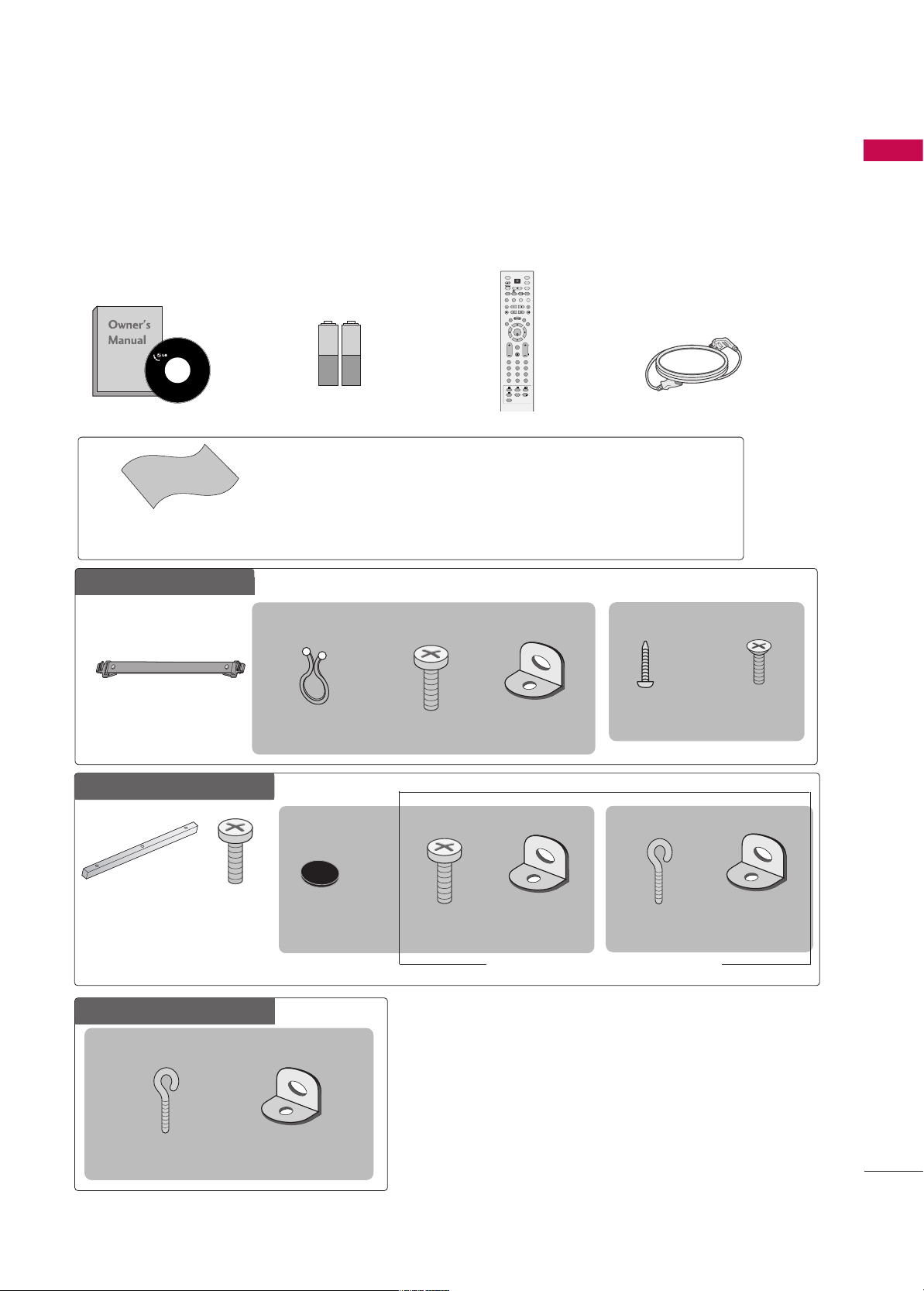
Ensure that the following accessories are included with your product. If an accessory is missing, please contact the dealer where you purchased the product.
Owner’s Manual
Remote Control
OK
TVD/A
INPUT
DVD
SIMPLINK
EXIT
VOL
SIZE
INDEX
TIME
REVEAL
Q.VIEW
PR
MARK
SUBTITLE
I/II
RATIO
TEXT
GUIDE
VCR
POWER
123
456
789
0
LIST
?
MODE
BRIGHT
MENU
MUTE
INPUT
FAV
SLEEP
PAGE
USB
INFO
i
1.5V
1.5V
Batteries
Cable Management
2- TV Bracket Bolts
2- TV Brackets,
2- Wall Brackets
Twist Holder
Arrange the wires with
the twist holder.
4-bolts for stand
assembly
Refer to p. 9
■
Carefully wipe stained spot on the exterior only with the polishing cloth for the product
exterior if there is stain or fingerprint on the surface of the exterior.
■
Do not wipe hard roughly when removing stain. Please be careful as excessive pressure may
cause a scratch or discoloration.
Polishing Cloth
Power Cord
Additional Cover
Refer to p. 16
FFoorr LLCCDD TTVV mmooddeellss
5500//6600PPYY33DDFF**oonnllyy
3 - Bolts
Refer to p. 16
2 - Rubber
Refer to p. 16
1-screw for stand
fixing
Refer to p. 10
This feature is not available for all models.
3322LL BB99DD**oonn llyy
6600PPYY33DDFF**oonn llyy
2- TV Bracket
Bolts
2- TV Brackets,
2- Wall Brackets
2-eye-bolts
2- Wall Brackets
5500PPYY33DDFF**oonn llyy
4422//5500PPBB44DD**oonnllyy
2- Wall Brackets
This feature is not available for all models.
This feature is not available for all models.
2-eye-bolts
This feature is not available
for all models.
Page 4

CONTENTS
2
CONTENTS
ACCESSORIES
. . . . . . . . . . . . . . . . . . . . . . . . . . . . . . . . . . . . . . . . . . .
1
PREPARATION
Front Panel Controls . . . . . . . . . . . . . . . . . . . . . . 4
Back Panel Information . . . . . . . . . . . . . . . . . . . . 6
Stand Installation . . . . . . . . . . . . . . . . . . . . . . . . . 9
Attaching the TV to a Desk . . . . . . . . . . . . . . . . 10
Swivel Stand . . . . . . . . . . . . . . . . . . . . . . . . . . . . 10
Attaching the TV to a Wall . . . . . . . . . . . . . . . . . 11
Back Cover for Wire Arrangement . . . . . . . . . . . 12
Desktop Pedestal Installation . . . . . . . . . . . . . . . 15
Wall Mount: Horizontal Installation . . . . . . . . . . 15
Not Using The Desk-type Stand . . . . . . . . . . . . 16
Antenna Connection . . . . . . . . . . . . . . . . . . . . . . 17
EXTERNAL EQUIPMENT SETUP
HD Receiver Setup . . . . . . . . . . . . . . . . . . . . . . . . . . . . . . . . . . . . . . . . . . 18
DVD Setup
. . . . . . . . . . . . . . . . . . . . . . . . . . . . . . . . . . . . . . . . . . . . . . . . . . . . . .21
VCR Setup
. . . . . . . . . . . . . . . . . . . . . . . . . . . . . . . . . . . . . . . . . . . . . . . . . . . . . .23
Other A/V Source Setup
. . . . . . . . . . . . . . . . . . . . . . . . . . . . . . . . . 25
PC Setup
. . . . . . . . . . . . . . . . . . . . . . . . . . . . . . . . . . . . . . . . . . . . . . . . . . . . . . . . 26
- Screen Setup for PC Mode . . . . . . . . . . . . . . . . . . . . . . . . . 29
USB In Setup
. . . . . . . . . . . . . . . . . . . . . . . . . . . . . . . . . . . . . . . . . . . . . . . . . . 31
AV Output Setup . . . . . . . . . . . . . . . . . . . . . . . . . . . . . . . . . . . . . . . . . . . .32
Digital Audio Output Setup
. . . . . . . . . . . . . . . . . . . . . . . . . . . . . 33
WATCHING TV / PROGRAMME CONTROL
Remote Control Key Functions . . . . . . . . . . . . . .34
Turning on the TV . . . . . . . . . . . . . . . . . . . . . . . . 36
Initializing Setup . . . . . . . . . . . . . . . . . . . . . . . . . 36
Programme Selection . . . . . . . . . . . . . . . . . . . . . 37
Volume Adjustment . . . . . . . . . . . . . . . . . . . . . . 37
On-Screen Menus Selection and Adjustment . . 38
Factory Reset . . . . . . . . . . . . . . . . . . . . . . . . . . . . 39
Model Info . . . . . . . . . . . . . . . . . . . . . . . . . . . . . . 39
Auto Programme Tuning . . . . . . . . . . . . . . . . . . .40
Manual Programme Tuning . . . . . . . . . . . . . . . . . 42
Fine Tuning . . . . . . . . . . . . . . . . . . . . . . . . . . . . . 44
Assigning a Station Name . . . . . . . . . . . . . . . . . 45
Programme Edit . . . . . . . . . . . . . . . . . . . . . . . . . .46
Input List . . . . . . . . . . . . . . . . . . . . . . . . . . . . . . . 48
Calling Up the Channel List . . . . . . . . . . . . . . . . 49
Input Source Selection . . . . . . . . . . . . . . . . . . . . 50
SIMPLINK . . . . . . . . . . . . . . . . . . . . . . . . . . . . . . . 51
Key Lock . . . . . . . . . . . . . . . . . . . . . . . . . . . . . . . 53
Entry Modes . . . . . . . . . . . . . . . . . . . . . . . . . . . . 54
Photo List . . . . . . . . . . . . . . . . . . . . . . . . . . . . . . 55
Music List . . . . . . . . . . . . . . . . . . . . . . . . . . . . . . 59
EPG(ELECTRONIC PROGRAMME GUIDE)
Switch on/off EPG . . . . . . . . . . . . . . . . . . . . . . . 62
Select a programme . . . . . . . . . . . . . . . . . . . . . . 62
Button Function in NOW/NEXT Guide Mode . 63
Button Function in 7 Days Guide Mode . . . . . . 63
Button Function in Extended Description Box . 64
Button Function in Reservation Setting Mode . 64
PICTURE CONTROL
Picture Size (Aspect Ratio) Control . . . . . . . . . .65
Preset Picture Settings
- Picture Mode - Preset . . . . . . . . . . . . . . . . 66
- Auto Colour Tone Control
(Warm/Medium/Cool) . . . . . . . . . . . . . . . .67
Manual Picture Adjustment
- Picture Mode - User Option . . . . . . . . . . . 68
- Colour Tone - User Option. . . . . . . . . . . . .69
Brightness Adjustment . . . . . . . . . . . . . . . . . . . . . . 70
XD - Picture Improvement Technology . . . . . . . . . . . 71
Advanced - Cinema . . . . . . . . . . . . . . . . . . . . . . . 72
Advanced - Black( Darkness) Level . . . . . . . . . . 73
Picture Reset . . . . . . . . . . . . . . . . . . . . . . . . . . . . 74
Image Sticking Minimization(ISM) Method . . . . 75
Low Power . . . . . . . . . . . . . . . . . . . . . . . . . . . . . . 76
Front Display(50/60PY3DF* only) . . . . . . . . . . 77
Page 5

CONTENTS
3
After reading this manual, keep it handy for future reference.
SOUND & LANGUAGE CONTROL
Auto Volume Leveler ( Auto Volume) . . . . . . . . . 78
Preset Sound Settings- Sound Mode . . . . . . . . 79
Sound Setting Adjustment - User Mode . . . . . . . . 80
Balance . . . . . . . . . . . . . . . . . . . . . . . . . . . . . . . . .82
TV Speakers On/ Off Setup . . . . . . . . . . . . . . . . 83
I/II
- Stereo/Dual Reception . . . . . . . . . . . . . . . . . 84
- Speaker Sound Output Selection . . . . . . . . 84
Subtitle . . . . . . . . . . . . . . . . . . . . . . . . . . . . . . . . 85
TIME SETTING
Clock Setting . . . . . . . . . . . . . . . . . . . . . . . . . . . . 86
Auto On/ Off Timer Setting . . . . . . . . . . . . . . . .88
Sleep Timer Setting . . . . . . . . . . . . . . . . . . . . . . .89
Auto Shut-off Setting . . . . . . . . . . . . . . . . . . . . . 90
PARENTAL CONTROL / RATINGS
Set Password & Lock System . . . . . . . . . . . . . . . 91
Programme Blocking . . . . . . . . . . . . . . . . . . . . . . 93
Parental Guidance . . . . . . . . . . . . . . . . . . . . . . . . 94
External Input Blocking . . . . . . . . . . . . . . . . . . . . 95
TELETEXT
Switch On/Off . . . . . . . . . . . . . . . . . . . . . . . . . . 96
Simple Text . . . . . . . . . . . . . . . . . . . . . . . . . . . . . 96
TOP Text . . . . . . . . . . . . . . . . . . . . . . . . . . . . . . . 96
Fastext . . . . . . . . . . . . . . . . . . . . . . . . . . . . . . . . . 97
Special Teletext Functions . . . . . . . . . . . . . . . . . 97
APPENDIX
Troubleshooting . . . . . . . . . . . . . . . . . . . . . . . . . .98
Maintenance . . . . . . . . . . . . . . . . . . . . . . . . . . .100
Product Specifications . . . . . . . . . . . . . . . . . . . 101
Programming the Remote Control . . . . . . . . . 104
IR Codes . . . . . . . . . . . . . . . . . . . . . . . . . . . . . . 107
External Control through RS-232C . . . . . . . . . 109
Open Source License . . . . . . . . . . . . . . . . . . . . . 115
Page 6

PREPARATION
4
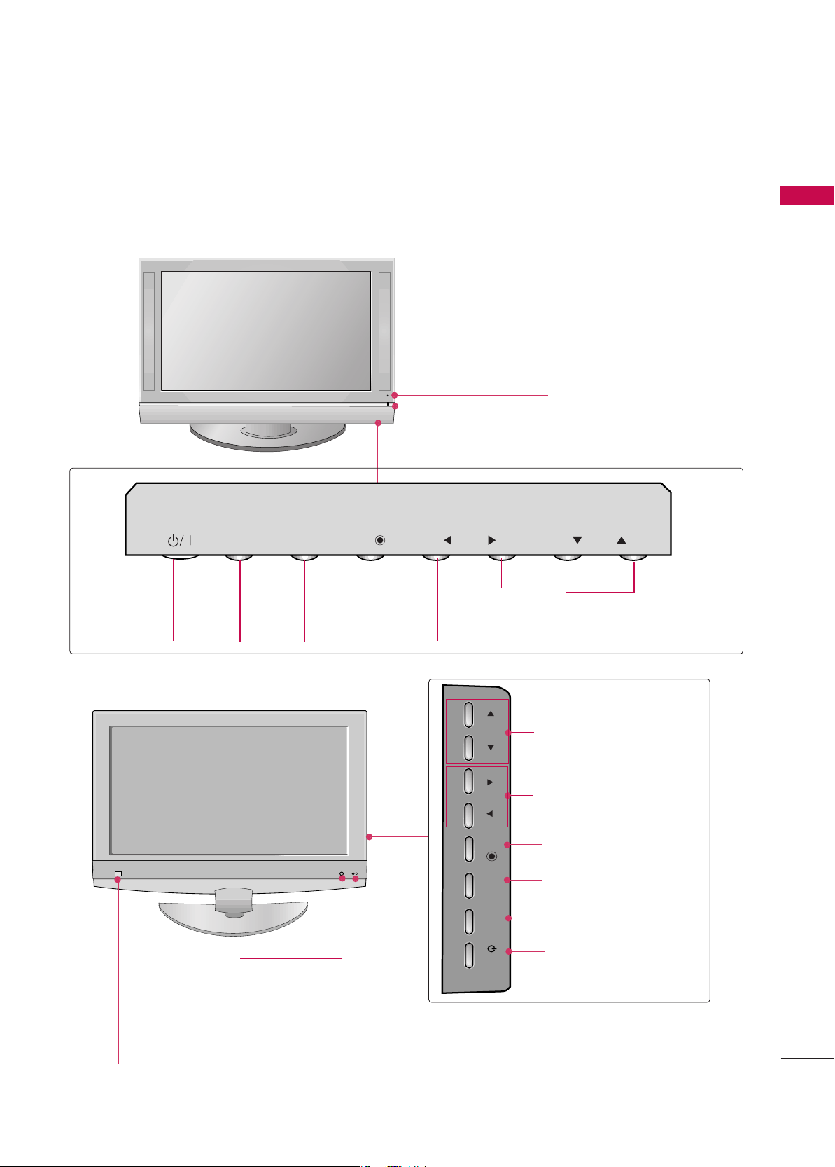
FRONT PANEL CONTROLS
PREPARATION
■
This is a simplified representation of the front panel. Image shown may be somewhat different from your TV.
■
If your product has a protection film attached, remove the film and then wipe the product with a polishing
cloth.
50/60PY3DF
**
Remote Control Sensor
OK
PR
VOLUME
(
FF,GG
)
Buttons
PROGRAMME
(
EE,DD
)
Buttons
OK
Button
MENU
Button
INPUT
Button
POWER
Button
Power Standby Indicator
• illuminates red in standby
mode.
• illuminates white when
the set is switched on.
Program Display
Touch Pad
OK
PR
Page 7
PREPARATION
5
42/50PB4D
**
CH
VOL
42/47/52LB9DF**, 32LB9D
**
CH
VOL
PROGRAMME
(
EE,DD
) Buttons
VOLUME
(
FF,GG
) Buttons
OK Button
MENU Button
INPUT Button
POWER Button
Remote Control
Sensor
Intelligent Eye
Adjusts picture
according to the
surrounding conditions.
Power/Standby Indicator
• illuminates red in standby mode.
• illuminates green when the set is switched on.
PROGRAMME
Buttons
VOLUME
Buttons
MENU
Button
OK
Button
INPUT
Button
POWER
Button
Remote Control Sensor
Power/Standby Indicator
• illuminates red in standby mode.
• illuminates green when the set is switched on.
INPUT
MENU
OK
VOL
PR
VOL
OK
MENU
INPUT
PR
/I
Page 8
USB
AV IN 2
L/ MONO
R
AUDIO
VIDEO
S-VIDEO
PREPARATION
6
PREPARATION
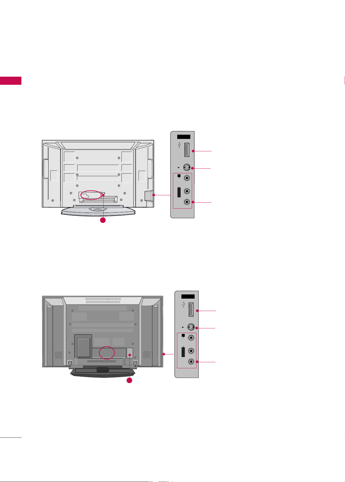
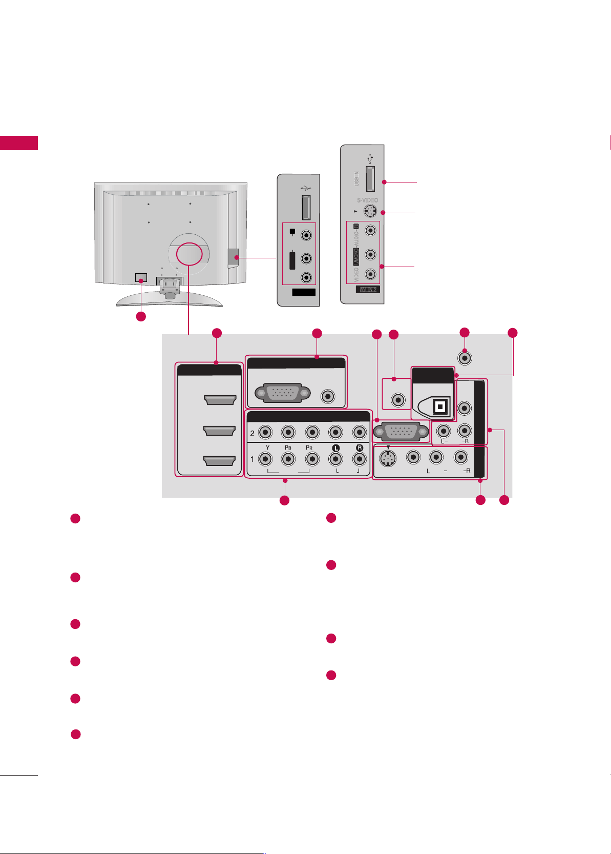
BACK PANEL INFORMATION
■
Image shown may be somewhat different from your TV.
50/60PY3DF
**
AV IN 2
L/MONO
R
AUDIO
VIDEO
S-VIDEO
USB
V IN 2
L/
MONO
AUDIO
VIDEO
USB
USB port
S-VIDEO Input
Connect S-Video out from an
S-VIDEO device.
AUDIO/VIDEO Input
Connect audio/video output from
an external device to these jacks.
42/50PB4D
**
Plasma TV Models
10
AV IN 2V IN 2
L/L/MONOMONO
R
AUDIOAUDIO
VIDEOVIDEO
S-VIDEO
USB USB
USB port
S-VIDEO Input
Connect S-Video out from an
S-VIDEO device.
AUDIO/VIDEO Input
Connect audio/video output from
an external device to these jacks.
10
AV IN 2
USB
S-VIDEO
R
AUDIO
MONO
L/
VIDEO
Page 9
PREPARATION
7
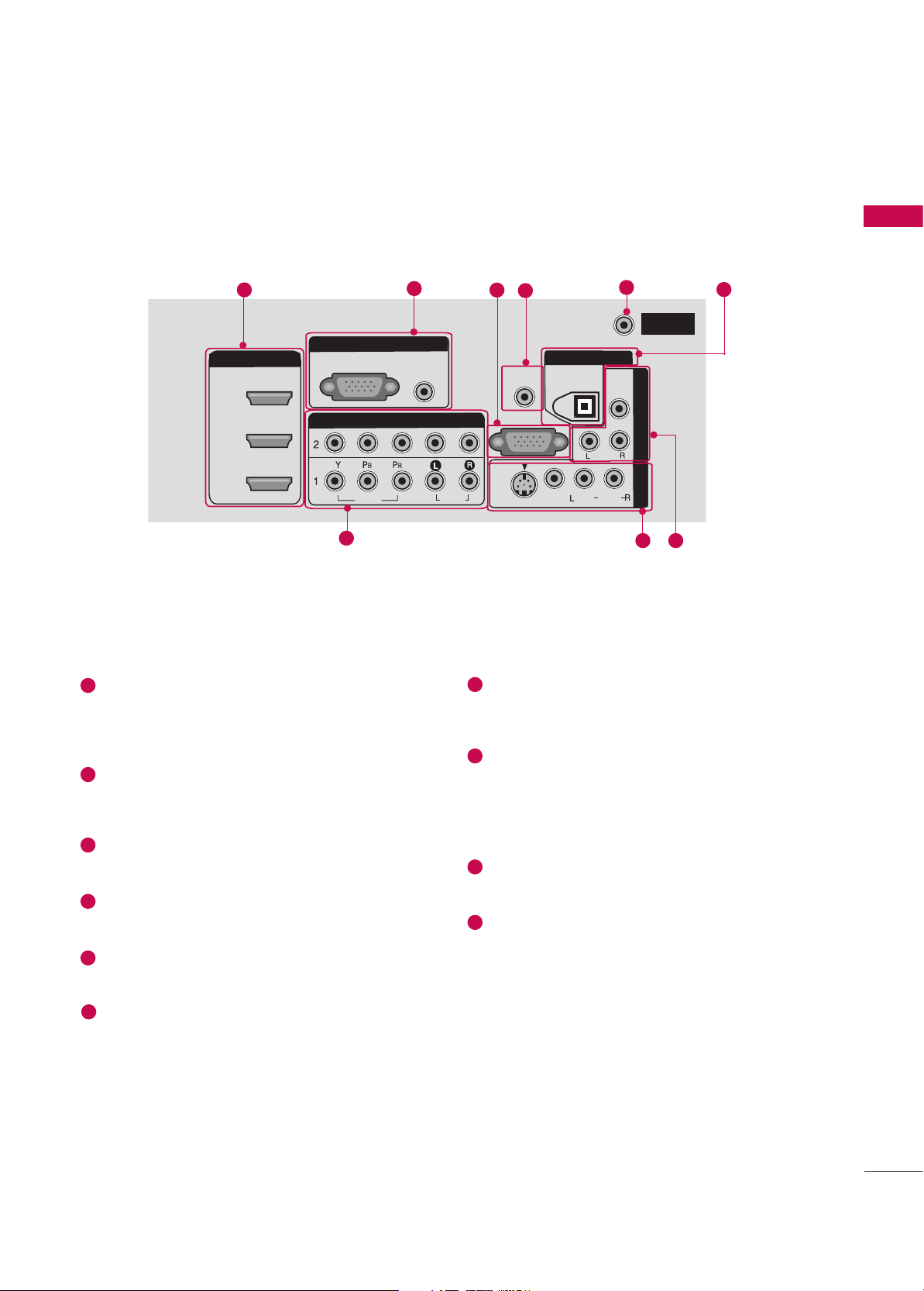
HDMI/DVI IN
Connect a HDMI signal.
Or DVI(VIDEO) signal to the this port with a
HDMI to DVI cable.
RGB/AUDIO IN
Connect the output from a set top box or PC to
the appropriate input port.
RS-232C IN (CONTROL &SERVICE) PORT
Connect to the RS-232C port on a PC.
Remote Control Port
Connect your wired remote control.
ANTENNA IN
Connect antenna signals to this jack.
DIGITAL AUDIO OUT
Connect digital audio from various types of
equipment. Note: In standby mode, these ports
do not work.
COMPONENT IN
Connect a component video/audio device to
these jacks.
AV (Audio/Video) IN 1
Connect audio/video output from an external
device to these jacks.
S-VIDEO
Connect S-Video out from an S-VIDEO device.
AV OUT
Connect a second TV or monitor.
Power Cord Socket
For operation with AC power.
Caution: Never attempt to operate the TV on DC
power.
1
6
7
8
9
10
2
3
4
5
HDMI/DVI INHDMI/DVI IN
2
1
COMPONENT INCOMPONENT IN
VIDEOVIDEO
AUDIOAUDIO
RGB INRGB IN
RGB (PC) RGB (PC)
AUDIO AUDIO
(RGB/DVI)(RGB/DVI)
AV IN 1AV IN
1
VIDEOVIDEO
S-VIDEOS-
VIDEO
AUDIOAUDIO
MONO
( )
RS-232C INRS-232C IN
(CONTROL & SERVICE)(CONTROL & SERVICE)
AV
OUT
AV OUT
REMOTEREMOTE
CONTROL INCONTROL IN
DIGITAL AUDIO DIGITAL AUDIO
OUTOUT
OPTICALPTICAL
VIDEOVIDEO
AUDIO
ANTENNAANTENNA
ININ
3
1
2
4
7
8
3
5
6
9
Page 10
PREPARATION
8
PREPARATION
■
Image shown may be somewhat different from your TV.
ANTENNAANTENNA
ININ
HDMI/DVI INHDMI/DVI IN
2
1
COMPONENT INCOMPONENT IN
VIDEOVIDEO
AUDIOAUDIO
RGB INRGB IN
RGB (PC) RGB (PC)
AUDIO AUDIO
(RGB/DVI)(RGB/DVI)
AV
IN 1
AV
IN
1
VIDEOVIDEO
S-VIDEOS-VIDEO
AUDIOAUDIO
MONO
( )
RS-232C INRS-232C IN
(CONTROL & SERVICE)(CONTROL & SERVICE)
AV
OUT
AV OUT
REMOTEREMOTE
CONTROL INCONTROL IN
DIGITALDIGITAL
AUDIO AUDIO
OUTOUT
OPTICALPTICAL
VIDEOVIDEO
S-VIDEO
AUDIO
3
1
2
4
7
8
3
5
6
9
USB Input
S-VIDEO Input
Connect S-Video out from
an S-VIDEO device.
AUDIO/VIDEO Input
Connect audio/video output
from an external device to
these jacks.
S-VIDEO
42/47/52LB9DF
**
AV IN 2V IN 2
L/L/MONOMONO
R
AUDIOAUDIO
VIDEOVIDEO
USB INUSB IN
32LB9D
**
AV IN 2
L/MONO
R
AUDIO
VIDEO
USB IN
HDMI/DVI IN
Connect a HDMI signal.
Or DVI(VIDEO) signal to the this port with a
HDMI to DVI cable.
RGB/AUDIO IN
Connect the output from a set top box or PC to
the appropriate input port.
RS-232C IN (CONTROL &SERVICE) PORT
Connect to the RS-232C port on a PC.
Remote Control Port
Connect your wired remote control.
ANTENNA IN
Connect antenna signals to this jack.
DIGITAL AUDIO OUT
Connect digital audio from various types of
equipment. Note: In standby mode, these ports
do not work.
COMPONENT IN
Connect a component video/audio device to
these jacks.
AV (Audio/Video) IN 1
Connect audio/video output from an external
device to these jacks.
S-VIDEO
Connect S-Video out from an S-VIDEO device.
AV OUT
Connect a second TV or monitor.
Power Cord Socket
For operation with AC power.
Caution: Never attempt to operate the TV on DC
power.
1
6
7
8
9
10
2
3
4
5
LCD TV Models
10
Page 11
PREPARATION
9
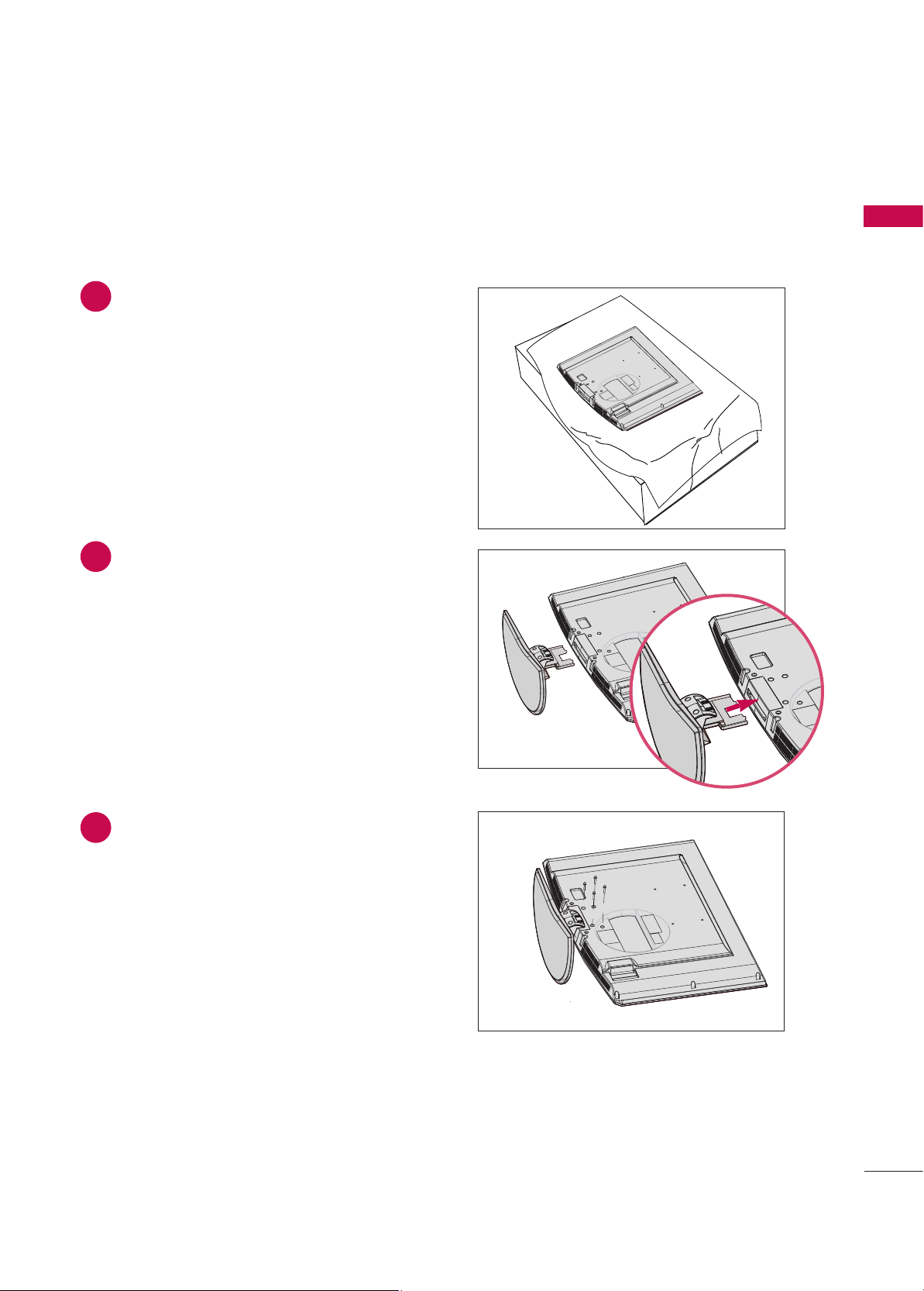
STAND INSTALLATION (
32LB9D
*
Only)
1
2
3
Carefully place the product screen side down on
a cushioned surface that will protect product and
screen from damage.
Assemble the product stand with the product as
shown.
Install the 4 bolts securely, in the back of the
product in the holes provided.
Page 12
PREPARATION
10
PREPARATION
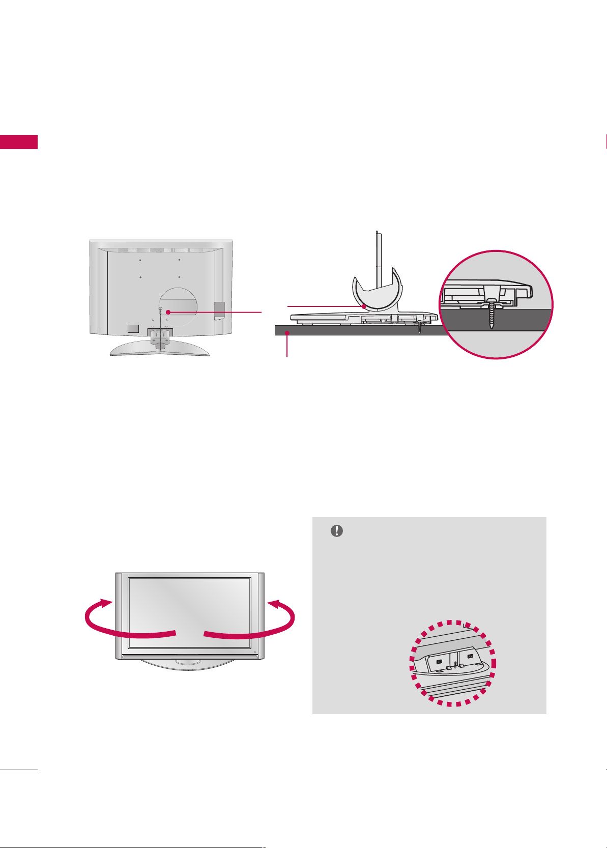
ATTACHING THE TV TO A DESK (32LB9D
**
Only)
If you wish to attach the TV to a desk, it must be securely fastened to the desk using a metal screw (as shown
below).
Failure to securely attach the TV may result in the TV falling: which may cause damage to the TV and serious
personal injury.
1-screw
Stand
Desk
SWIVEL STAND
50/
60PY3DF
**
models
After installing the TV, you can adjust the the TV set manually to the left or right direction by 20 degrees to
suit your viewing position.
NOTE
GG
Before adjusting the angle, you must remove
the cable management and loosen (to the
left) the shaft bolt on the middle of stand’s
back. And when stand be level with TV, you
must close (to the right) the shaft bolt to
set the hole.
Page 13
PREPARATION
11
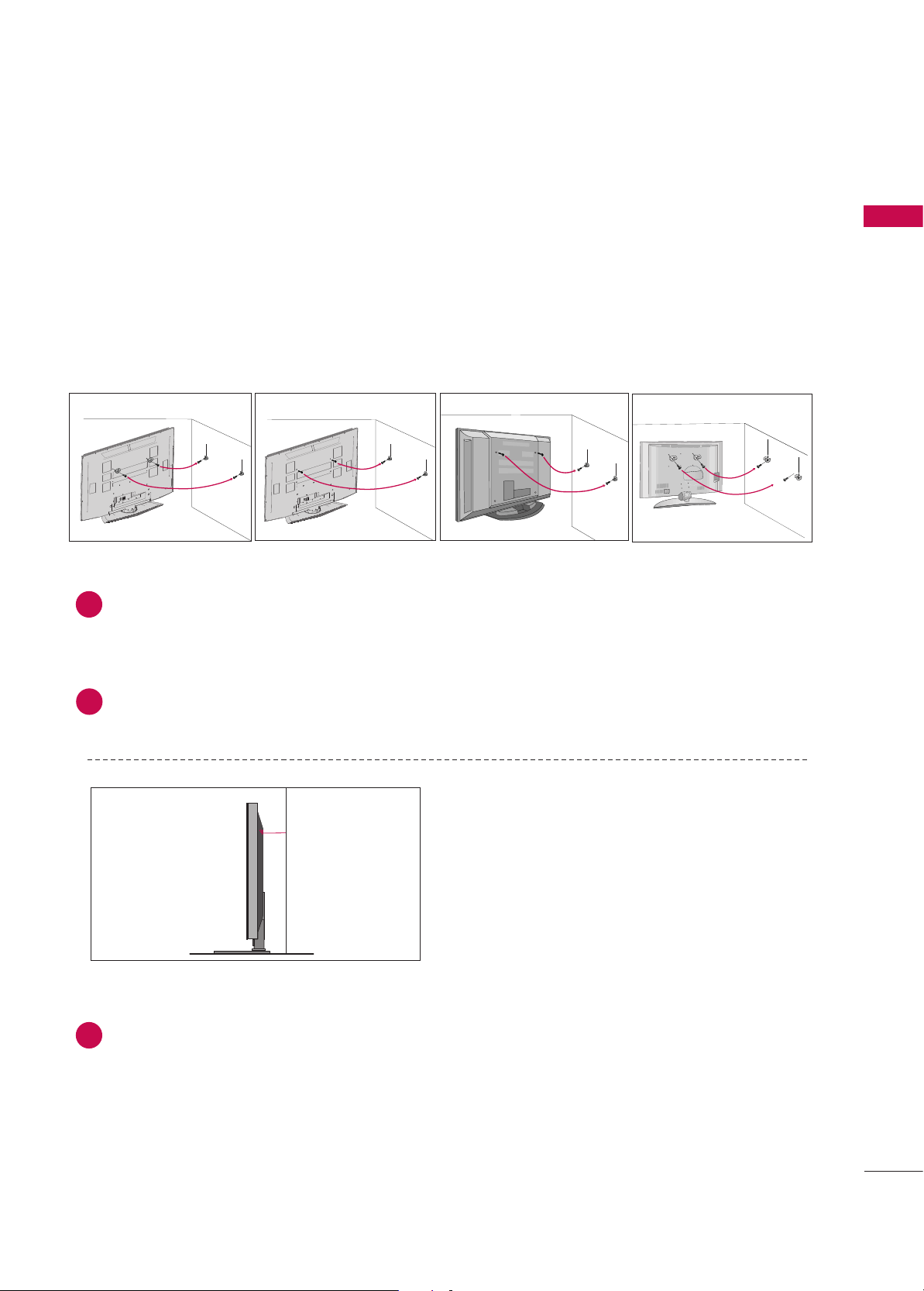
ATTACHING THE TV TO A WALL
■
This Feature is not available for all models.
A
Set it up close to the wall so the product doesn’t fall over when it is pushed backwards.
A
The instructions shown below is a safer way to set up the product, which is to fix it on the wall so the
product doesn’t fall over when it is pulled in the forward direction. It will prevent the product from
falling forward and hurting people. It will also prevent the product from damage caused by fall. Please
make sure that children don’t climb on or hang from the product.
Use the eye-bolts or TV brackets/bolts to fix the product to the wall as shown in the picture.
(If your product has the bolts in the eye-bolts position before inserting the eye-bolts, loosen the bolts.)
* Insert the eye-bolts or TV brackets/bolts and tighten them securely in the upper holes.
Secure the wall brackets with the bolts (not provided as parts of the product, must purchase separately) on
the wall. Match the height of the bracket that is mounted on the wall.
1
2
Use a sturdy rope (not provided as parts of the product, must purchase separately) to tie the
product. It is safer to tie the rope so it becomes horizontal between the wall and the product.
3
3
42/50PB4D
**
60PY3DF
**
42/47/52LB9DF**, 32LB9D
**
2
1
2
1
50PY3DF
**
2
1
2
1
Page 14
PREPARATION
12
PREPARATION
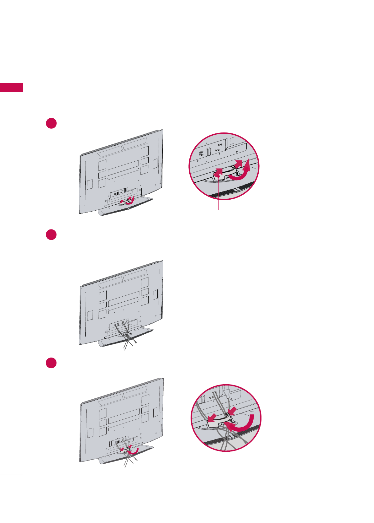
Hold the CABLE MANAGEMENT with both hands and pull it as shown.
Connect the cables as necessary.
To connect additional equipment, see the External equipment Setup section.
1
2
Install the CABLE MANAGEMENT as shown.
3
CABLE MANAGEMENT
50/60PY3DF
**
45
°
BACK COVER FOR WIRE ARRANGEMENT
■
Here shown may be somewhat different from your TV.
Page 15
PREPARATION
13
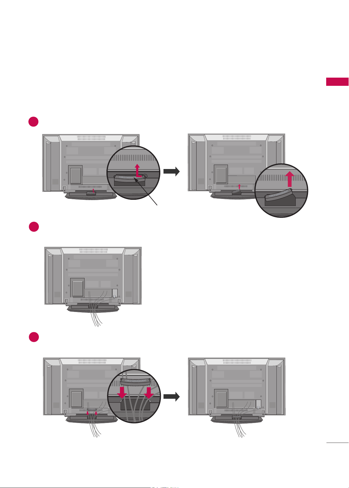
Connect the cables as necessary.
To connect an additional equipment, see the
EExxtteerrnnaall eeqquuiippmmeenntt SSeettuupp
section.
Reinstall the
CCAABBLLEE MMAANNAAGGEE MMEE NNTT
as shown.
Hold the
CCAABBLLEE MMAANNAAGGEE MMEE NNTT
with hands and push it as shown.
CABLE MANAGEMENT
42/50PB4D
**
1
2
3
Page 16

PREPARATION
14
PREPARATION
Connect the cables as necessary.
To connect additional equipment, see the
EExxtteerrnnaall EEqquuiippmmeenntt SSeettuupp
section.
Install the
CCAABBLLEE MMAANNAAGGEE MMEE NNTT
as shown.
(Insert it as pushing the loops on the both
sides of the cable management.)
(This Feature is not available for all models.)
Bundle the cables using the supplied twist holder.
(This Feature is not available for all models.)
Hold the
CCAABBLLEE MMAANNAAGGEE MMEE NNTT
with both hands
and pull it upward.
(Pull it out as holding the loops on the both sides of
the cable management.)
NOTE
!
GG
Do not hold the CABLE MANAGEMENT when moving the product.
- If the product is dropped, you may be injured or the product may be broken.
How to remove the cable management
1
2
3
TWIST HOLDER
CABLE MANAGEMENT
42/47/52LB9DF**, 32LB9D
**
Page 17
PREPARATION
15
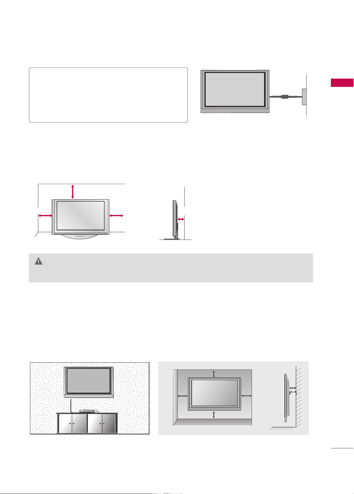
GG
Ensure adequate ventilation by following the clearance recommendations.
CAUTION
Power Supply
Short-circuit
Breaker
GROUNDING
Ensure that you connect the earth ground wire to prevent
possible electric shock. If grounding methods are not possible, have a qualified electrician install a separate circuit
breaker.
Do not try to ground the unit by connecting it to telephone wires, lightening rods, or gas pipes.
DESKTOP PEDESTAL INSTALLATION
For proper ventilation, allow a clearance of 4inches on all four sides from the wall.
4 inches
4 inches
4 inches
4 inches
WALL MOUNT: HORIZONTAL INSTALLATION
For proper ventilation, allow a clearance of 4" on each side and from the wall.
Detailed installation instructions are available from your dealer.
4 inches
4 inches
4 inches
4 inches
4 inches
Page 18
PREPARATION
16
PREPARATION
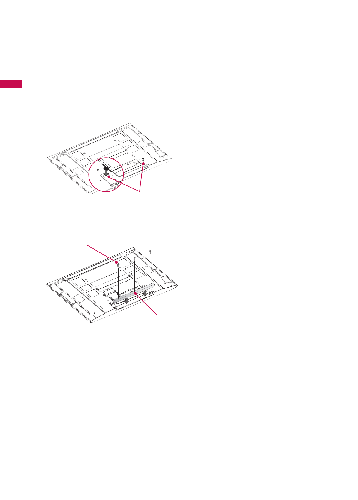
NOT USING THE DESK-TYPE STAND(Only
50/60PY3DF
*
model)
When not using the desk-type stand, install the
supplied desk-type stand fixture protection rubber
caps as shown at the figure.
To prevent the foreign materials from entering the
desk-type stand fixture, fix the desk-type stand fixture protection cover(additional cover) by using
the supplied bolts as shown at the figure.
ADDITIONAL COVER
BOLT
RUBBER
■
It is applied to when installing only the 60PY3DF*model as wall-type.
■
It is applied to when installing only the 50/60PY3DF*model as wall-type.
Page 19
USB
AV IN 2
L/MONO
R
AUDIO
VIDEO
S-VIDEO
PREPARATION
17
■
To prevent the equipment damage, never plug in any power cords until you have finished connecting all equipment.
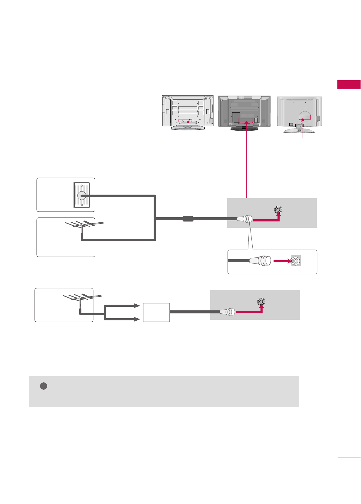
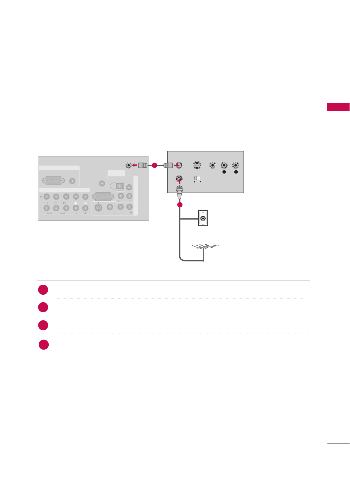
ANTENNA CONNECTION
Wall Antenna Socket or Outdoor Antenna without a Cable Box Connections. For optimum
picture quality, adjust antenna direction if
needed.
AV IN 2
L/MONO
R
AUDIO
VIDEO
S-VIDEO
USB
AV IN 2
L/MONO
R
AUDIO
VIDEO
USB IN
Multi-family Dwellings/Apartments
(Connect to wall antenna socket)
Single-family Dwellings /Houses
(Connect to wall jack for outdoor antenna)
Outdoor
Antenna
(VHF, UHF)
Wall
Antenna
Socket
RF Coaxial Wire (75 ohm)
GG
The TV will let you know when the analogue, cable, and digital programme scans are complete.
NOTE
!
ANTENNA
IN
■
To improve the picture quality in a poor signal area, please purchase a signal amplifier and install properly.
■
If the antenna needs to be split for two TV’s, install a 2-Way Signal Splitter.
■
If the antenna is not installed properly, contact your dealer for assistance.
Antenna
UHF
Signal
Amplifier
VHF
ANTENNA
IN
Page 20

EXTERNAL EQUIPMENT SETUP
18
EXTERNAL EQUIPMENT SETUP
■
To prevent the equipment damage, never plug in any power cords until you have finished connecting all equipment.
■
This part of EXTERNAL EQUIPMENT SETUP mainly use pictures for the
LCD TV
models.
HD RECEIVER SETUP
When connecting with a Component cables
Connect the video outputs (Y, PB, PR
)
of the digital set
top box to the
CCOOMMPPOONNEENNTT IINN VVIIDDEEOO 11
jacks on
the set. Match the jack colours.
(Y = green, P
B = blue, and PR = red)
Connect the audio output of the digital set-top box to
the
CCOOMMPPOONNEENNTT IINN AAUUDDIIOO 11
jacks on the set.
Turn on the digital set-top box.
(
Refer to the owner’s manual for the digital set-top box.
)
Select
CCoommppoonneenn tt 11
input source using the
IINNPPUUTT
button on the remote control.
If connected to
CCOOMMPPOONNEENNTT IINN 22
input, select
CCoommppoonneenn tt 22
input source.
2
1
Signal
480i
480p
576i
576p
720p
10 8 0 i
10 8 0 p
Component 1/2
Yes
Yes
Yes
Yes
Yes
Yes
Yes
HDMI/DVI 1, 2, 3
No
Yes
No
Yes
Yes
Yes
Yes
3
4
RGB IN
RGB (PC)
DIGITAL
AUDIO
OUT
COMPONENT INCOMPONENT IN
VIDEOVIDEO
AUDIOAUDIO
Y L RPB PR
1
2
Page 21

EXTERNAL EQUIPMENT SETUP
19
When connecting with HDMI cable
Connect the digital set-top box to
HHDDMMII//DDVV II IINN 11, 22
or
33
jack on the set.
No separate audio connection is necessary.
Turn on the digital set-top box.
(Refer to the owner’s manual for the digital set-top box.)
Select
HHDDMMII11,HHDDMMII22 orHHDDMMII33
input source using the
IINNPPUUTT
button on the remote control.
2
1
GG
If the digital set-top box supports Auto HDMI function, the
output resolution of the source device will be automatically
set to 1280x720p.
GG
If the digital set-top box player does not support Auto
HDMI, you need to set the output resolution appropriately.
To get the best picture quality, adjust the output resolution
of the source device to 1920x1080i/1080p. (32LB9D*,
42/50PB4D*: 1280x720p)
NOTE
!
3
4
COMPONENT INCOMPONENT IN
VIDEOVIDEO
AUDAUDIO
RGB INRGB IN
RGB (PC) RGB (PC)
AUDIO
(RGB/DVI)
DIGITAL
AUDIO
OUT
HDMI/DVI INHDMI/DVI IN
2
1
HDMI-DTV OUTPUT
COMPONENT IN
VIDEO
HDMI/DVI IN
RGB IN
AUDIO
(RGB/DVI)
3
1
Page 22
EXTERNAL EQUIPMENT SETUP
20
EXTERNAL EQUIPMENT SETUP
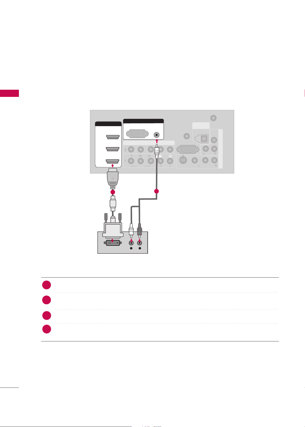
When connecting HDMI to DVI cable
ANTENNA
IN
COMPONENT INCOMPONENT IN
VIDEOVIDEO
AUDIOAUDIO
A
V
IN
1
VIDEO
S-VIDEO
AUDIO
MONO
( )
RS-232C IN
(CONTROL & SERVICE)
A
V
OU
T
REMOTE
CONTROL IN
DIGITALDIGITAL
AUDIO AUDIO
OUTOUT
OPTICAL
HDMI/DVI INHDMI/DVI IN
1
RGB INRGB IN
RGB (PC)
AUDIO AUDIO
(RGB/DVI)(RGB/DVI)
L R
DVI-DTV OUTPUT
VIDEO
AUDIO
2
3
Connect the DVI output of the digital set-top box to the
HHDDMMII//DDVV II IINN11, 22
or
33
jack on the set.
Connect the audio output of the digital set-top box to the
AAUUDDII OO((RRGGBB//DDVVII))
jack on the set.
Turn on the digital set-top box. (Refer to the owner’s manual for the digital set-top box.
)
Select
HHDDMMII11,HHDDMMII22 orHHDDMMII33
input source with using the
IINNPPUUTT
button on the remote control.
2
1
1
2
3
4
Page 23
EXTERNAL EQUIPMENT SETUP
21
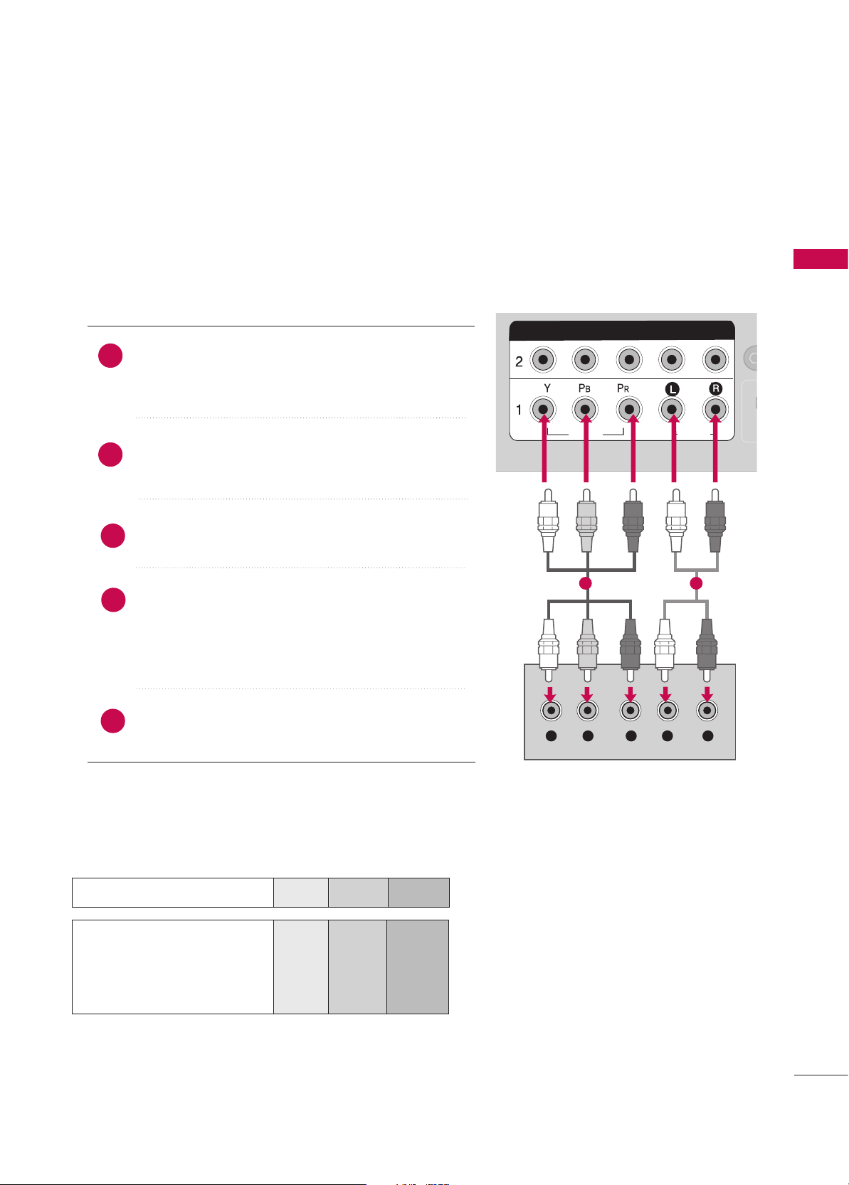
When connecting Component cables
RGB IN
RGB (PC)
S
(C
DIGITAL
AUDIO
OUT
COMPONENT INCOMPONENT IN
VIDEOVIDEO
AUDIOAUDIO
Y L RPB PR
HDMI/DVI IN
2
1
RGB (PC)
(DVI)
Component Input ports
To get better picture quality, connect a DVD player to the component input ports as shown below.
Component ports on the TV
YPB PR
Video output ports
on DVD player
Y
Y
Y
Y
PB
B-Y
Cb
Pb
P
R
R-Y
Cr
Pr
Connect the video outputs (Y, P
B, PR) of the DVD to the
CCOOMMPPOO NNEE NNTT IINN VVII DDEEOO 11
jacks on the set.
Match the jack colours (Y = green, P
B = blue, and PR = red).
Connect the audio outputs of the DVD to the
CCOOMM PP OO--
NNEENN TT IINN AAUUDDIIOO11
jacks on the set.
Turn on the DVD player, insert a DVD.
Select
CCoommppoonnee nn tt 11
input source using the
IINNPPUUTT
button on the remote control.
If connected to
CCOOMMPPOO NNEENNTT IINN 22
input, select
CCoommppoonnee nn tt 22
input source.
Refer to the DVD player's manual for operating instructions.
2
1
1 2
3
4
5
DVD SETUP
Page 24
EXTERNAL EQUIPMENT SETUP
22
EXTERNAL EQUIPMENT SETUP
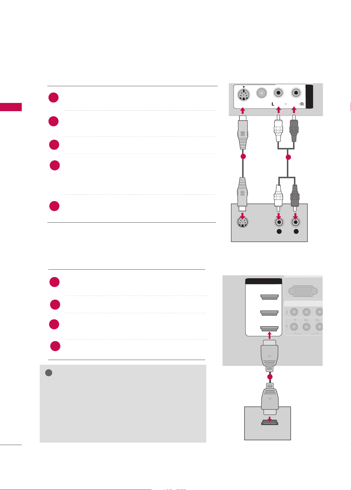
When connecting with an S-Video cable
DIGITAL
AUDIO
OUT
A
V
IN
1
A
V
IN
1
VIDEOVIDEO
AUDIOAUDIO
MONO
( )
S-VIDEOS-VIDEO
L R
S-VIDEO
AUDIO
UO
1
2
Connect the S-VIDEO output of the DVD to the
SS--VVIIDDEEOO
input on the set.
Connect the audio outputs of the DVD to the
AAUUDDIIOO
input jacks on the set.
Turn on the DVD player, insert a DVD.
Select
AA VV11
input source using the
IINN PPUUTT
button on the
remote control.
If connected to
AAVV II NN 22
input, select
AA VV22
input
source.(Except 32LB9D*)
Refer to the DVD player's manual for operating instructions.
2
1
3
4
5
COMPONENCOMPONENT IN
VIDEOVIDEO
AUDIO
RGB INRGB IN
RGB (PC) RGB (PC)
A
(R
DIGITAL
AUDIO
OUT
HDMI/DVI INHDMI/DVI IN
2
1
HDMI-DVD OUTPUT
VIDEO
AUDIO
A
V
IN
VIDEO
AUDIO
( )
S-VIDEO
3
1
When connecting HDMI cable
Connect the HDMI output of the DVD to the
HHDDMMII//DDVV II IINN11, 22 or33
jack on the set.
No separate audio connection is necessary.
Select
HHDDMMII11,HHDDMMII22 orHHDDMMII33
input source using the
IINNPPUUTT
button on the remote control.
Refer to the DVD player's manual for operating instructions.
2
1
GG
If the DVD supports Auto HDMI function, the DVD output
resolution will be automatically set to 1280x720p.
GG
If the DVD does not support Auto HDMI, you need to set
the output resolution appropriately.
To get the best picture quality, adjust the output resolution of
the DVD to 1920x1080i/1080p. (32LB9D*, 42/50PB4D*:
1280x720p)
NOTE
!
3
4
Page 25
EXTERNAL EQUIPMENT SETUP
23
VCR SETUP
When connecting with an antenna
■
To avoid picture noise (interference), leave an adequate distance between the VCR and TV.
■
If the 4:3 picture format is used; the fixed images on the sides of the screen may remain visible on the
screen. This phenomenon is common to all manufacturers and in consequence the manufacturer’s warranty
does not cover the product bearing this phenomenon.
COMPONENT INCOMPONENT IN
VIDEOVIDEO
AUDIOAUDIO
RGB INRGB IN
RGB (PC) RGB (PC)
AUDIO
(RGB/DVI)
AV IN
1
VIDEO
AUDIO
MONO
( )
RS-232C IN
(CONTROL & SERVICE)
AV
OUT
REMOTE
CONTROL IN
DIGITALDIGITAL
AUDIO AUDIO
OUTOUT
OPTICAL
S-VIDEO
ANTENNAANTENNA
ININ
HDMI/DVI IN
2
1
COMPONENT IN
VIDEO
AUDIO
RGB IN
RGB (PC)
DIGITAL
AUDIO
OUT
A
V IN
1
VIDEO
AUDIO
( )
HDMI/DVI IN
2
1
COMPONENT IN
VIDEO
AUDIO
RGB IN
RGB (PC)
S-VIDEO
VIDEO
(DVI)
(DVI)
AUDIO
L R
S-VIDEO VIDEO
OUTPUT
SWITCH
ANT IN
ANT OUT
Wall Jack
Antenna
1
2
Connect the RF antenna out socket of the VCR to the
AANN TTEENNNNAA II NN
socket on the set.
Connect the antenna cable to the RF antenna in socket of the VCR.
Set VCR output switch to 3 or 4 and then tune TV to the same programme number.
Insert a video tape into the VCR and press PLAY on the VCR. (Refer to the VCR owner’s manual.
)
2
1
3
4
Page 26
EXTERNAL EQUIPMENT SETUP
24
EXTERNAL EQUIPMENT SETUP
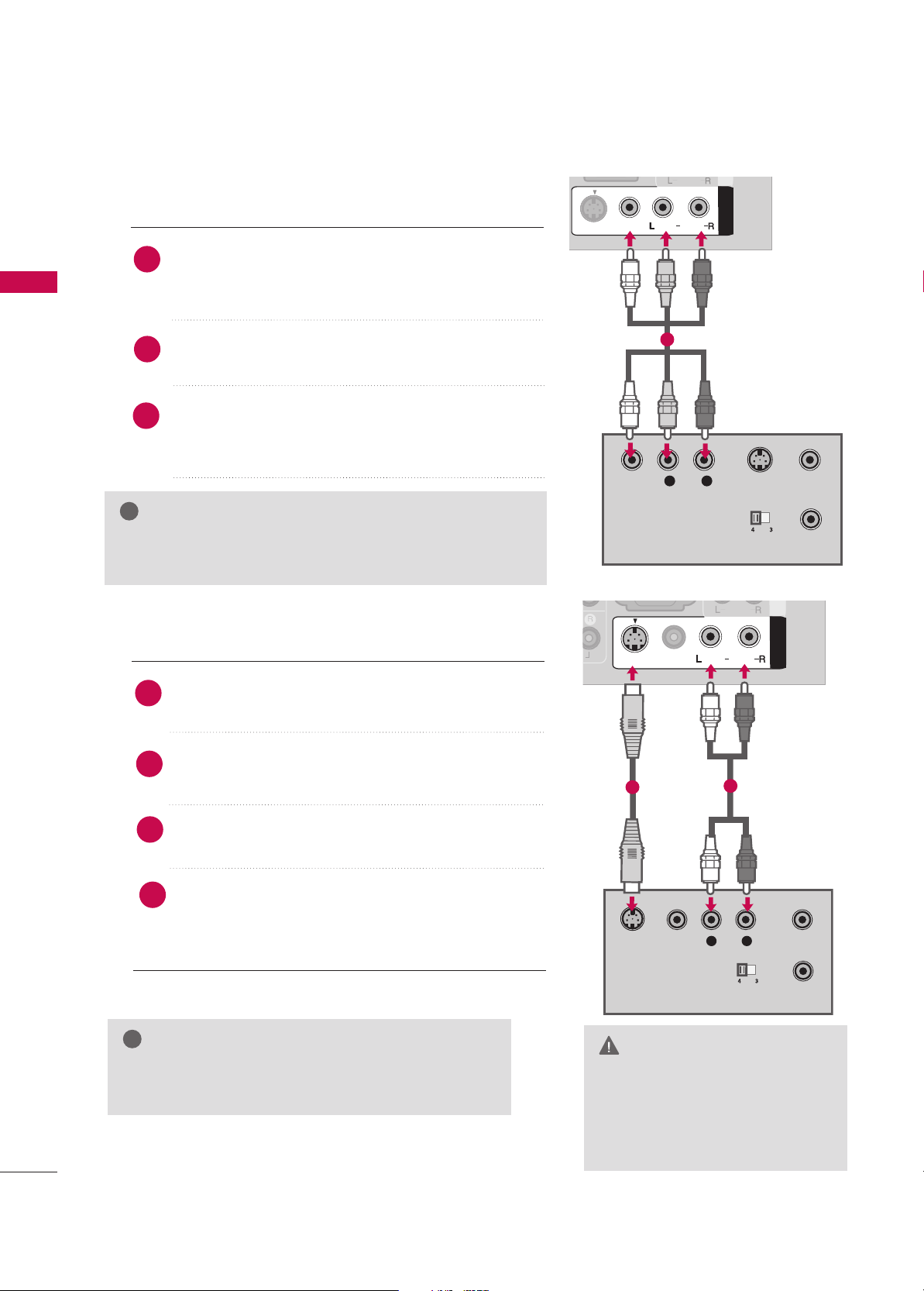
When connecting with an RCA cable
DIGITAL
AUDIO
OUT
A
V IN 1AV IN
1
VIDEOVIDEO
AUDIOAUDIO
MONO
( )
S-VIDEO
L R
S-VIDEOVIDEO
OUTPUT
SWITCH
ANT IN
ANT OUT
AUDIO
Connect the
AAUUDDIIOO/VVIIDDEEOO
jacks between TV and
VCR. Match the jack colours(Video = yellow, Audio Left =
white, and Audio Right = red)
Insert a video tape into the VCR and press PLAY on the
VCR. (Refer to the VCR owner’s manual.
)
Select
AA VV11
input source using the
IINN PPUUTT
button on
the remote control.
If connected to
AAVV II NN22
, select
AA VV22
input source.
1
GG
If you have a mono VCR, connect the audio cable from the
VCR to the
AAUUDDIIOO LL((MMOONNOO))
jack of the set.
NOTE
!
1
3
2
GG
Do not connect to both Video
and S-Video at the same time. In
the event that you connect both
Video and the S-Video cables,
only the S-Video will work.
CAUTION
GG
The picture quality is improved: ; compared to normal
composite (RCA cable) input.
NOTE
!
DIGITAL
AUDIO
OUT
A
V IN 1AV IN
1
VIDEOVIDEO
AUDIOAUDIO
MONO
( )
S-VIDEOS-VIDEO
L R
S-VIDEO
VIDEO
OUTPUT
SWITCH
ANT IN
ANT OUT
AUDIO
When connecting with an S-Video cable
Connect the S-VIDEO output of the VCR to the
SS--VVIIDDEEOO
input on the set.
Connect the audio outputs of the VCR to the
AAUUDDIIOO
input jacks on the set.
Insert a video tape into the VCR and press PLAY on the
VCR. (Refer to the VCR owner’s manual.
)
Select
AAVV11
input source using the
IINNPPUUTT
button on
the remote control.
If connected to
AAVV II NN 22
input, select
AA VV22
input
source.(Except 32LB9D*)
2
1
1
2
3
4
Page 27
EXTERNAL EQUIPMENT SETUP
25
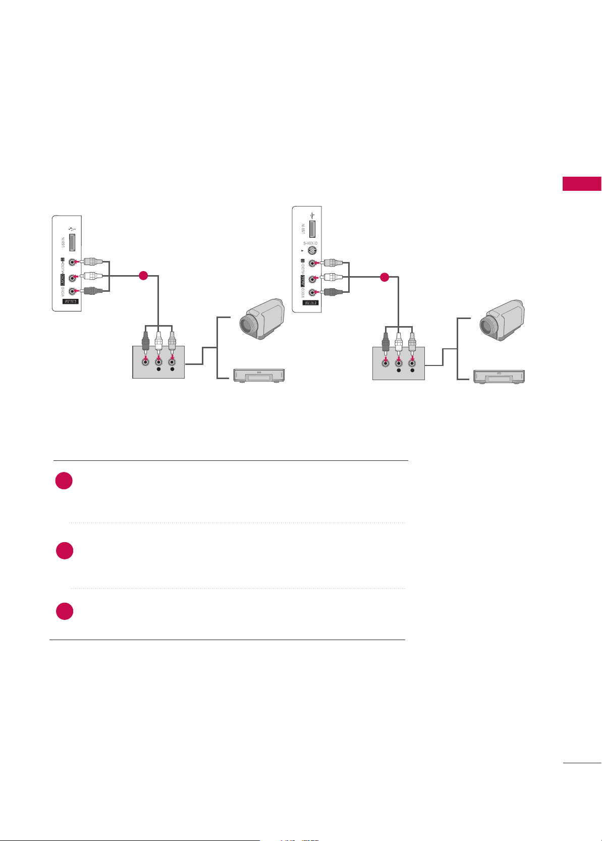
OTHER A/V SOURCE SETUP
Camcorder
Video Game Set
S-VIDEO
L R
VIDEO
L R
VIDEO
1
Camcorder
Video Game Set
32 inches
42/47/50/52/60 inches
1
Connect the
AAUUDDIIOO/VVIIDDEEOO
jacks between TV and
external equipment. Match the jack colours
.(Video = yellow, Audio Left = white,
and Audio Right = red
)
Select
AAVV22
input source using the
IINNPPUUTT
button on the remote control.
If connected to
AAVV IINN11
input, select
AAVV11
input source.
Operate the corresponding external equipment.
1
2
3
Page 28
EXTERNAL EQUIPMENT SETUP
26
EXTERNAL EQUIPMENT SETUP
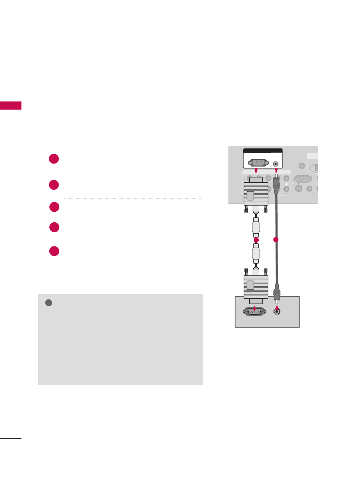
PC SETUP
This TV provides Plug and Play capability, meaning that the PC adjusts automatically to the TV's settings.
The TV perceives 1024x768, 60Hz as DTV 720p based on the PC graphic card. If necessary, change the
screen scanning rate for the graphic card accordingly.
When connecting D-sub 15pin cable
GG
Check the image on your TV. There may be noise associated with the resolution, vertical pattern, contrast or
brightness in PC mode. If noise is present, change the PC
output to another resolution, change the refresh rate to
another rate or adjust the brightness and contrast on the
VIDEO menu until the picture is clear. If the refresh rate of
the PC graphic card can not be changed, change the PC
graphic card or consult the manufacturer of the PC
graphic card.
NOTE
!
ANTEN
IN
COMPONENT INCOMPONENT IN
VIDEOVIDEO
AUDIOAUDIO
VIDEO
S-VIDEO
MON
(
RS-232C IN
(CONTROL & SERVICE)
REMOTE
CONTROL IN
DIGITADIGITAL
AUDIO AUDIO
OOUT
OPTICA
RGB INRGB IN
RGB (PC)
AUDIO
(RGB/DVI)
RGB OUTPUT
AUDIO
Connect the RGB output of the PC to the
RRGGBB
((
PPCC))
jack on the set.
Connect the PC audio output to the
AAUUDDIIOO
((
RRGGBB//DDVVII
))
jack on the set.
Turn on the PC and the set.
Select
RRGGBB--PPCC
input source in input option of Special
menu.
Once you select
RRGGBB--PPCC
in input option of Special
menu,
IINNPPUUTT
button is also available for this purpose.
2
1
1
2
4
3
5
Page 29

EXTERNAL EQUIPMENT SETUP
27
When connecting HDMI to DVI cable
GG
If the PC has a DVI output and no HDMI output, a separate audio connection is necessary.
GG
If the PC does not support Auto DVI, you need to set the output resolution appropriately. To get the
best picture quality, adjust the PC graphics card's output resolution to 1920x1080, 60Hz. (42PB4D* :
1024x768p, 32LB9D*/50PB4D*: 1360x768p)
NOTE
!
ANTENNA
IN
COMPONENT INCOMPONENT IN
VIDEOVIDEO
AUDIOAUDIO
AV I N 1
VIDEO
S-VIDEO
AUDIO
MONO
( )
RS-232C IN
(CONTROL & SERVICE)
AV O UT
REMOTE
CONTROL IN
DIGITALDIGITAL
AUDIO AUDIO
OUTOUT
OPTICAL
HDMI/DVI INHDMI/DVI IN
1
RGB INRGB IN
RGB (PC)
AUDIO AUDIO
(RGB/DVI)(RGB/DVI)
L R
DVI-PC OUTPUT
VIDEO
COMPONENT IN
VIDEO
AUDIO
DIGITAL
AUDIO
OUT
RGB IN
AUDIO
2
3
Connect the DVI output of the PC to the
HHDDMMII//DDVVII IINN11, 22
or
33
jack on the set.
(Use the HDMI to DVI cable)
Connect the PC audio output to the
AAUUDDIIOO ((RRGGBB//DDVVII
))
jack on the set.
Turn on the PC and the set.
Select
HHDDMMII11,HHDDMMII22 orHHDDMMII33
input source using the
IINNPPUUTT
button on the remote control.
2
1
1
2
4
3
Page 30
EXTERNAL EQUIPMENT SETUP
28
EXTERNAL EQUIPMENT SETUP
NOTES
!
Supported Display Specifications (RGB/HDMI-PC
)
Supported Display Specifications (HDMI-DTV
)
Supported Display Specifications (Component
)
Horizontal Vertical
Frequency(kHz)Frequency(Hz
)
15.625 50.00
31.25 50.00
15.75 60.00
15.73 59.94
31.47 59.94
31.50 60.00
45.00 60.00
44.96 59.94
37.50 50.00
33.75 60.00
33.72 59.94
28.125 50.00
26.97 23.976
27.00 24.00
33.716 29.97
33.750 30.00
56.25 50.00
67.43 59.94
67.50 60.00
Resolution
1280x720p
1920x1080i
720x480i
GG
Depending on the graphics card, DOS mode
may not work if a HDMI to DVI Cable is in use.
GG
Avoid keeping a fixed image on the screen for a
long period of time. The fixed image may
become permanently imprinted on the screen.
GG
The synchronization input form for Horizontal
and Vertical frequencies is separate.
Horizontal Vertical
Frequency(kHz)Frequency(Hz
)
31.469 59.940
37.500 75.000
31.469 70.08
37.879 60.317
46.875 75.000
48.363 60.004
56.476 70.069
60.023 75.029
47.776 59.870
47.712 60.015
47.13 59.65
63.981 60.020
79.976 75.025
75.000 60.000
67.500 60.000
Resolution
720x400
1280x1024
640x480
800x600
1024x768
1280x768
1600x1200
1920x1080
1360x768
Horizontal Vertical
Frequency(kHz)Frequency(Hz
)
31.25 50.00
31.47 59.94
31.50 60.00
37.50 50.00
44.96 59.94
45.00 60.00
33.72 59.94
33.75 60.00
28.125 50.00
26.97 23.976
27.00 24.00
33.716 29.97
33.750 30.00
56.25 50.00
67.43 59.94
67.50 60.00
Resolution
720x480p
720x576p
1280x720p
1920x1080i
720x576i
Except 32LB9D*, 42PB4D*
1920x1080p
720x576p
720x480p
1920x1080p
1366x768
Except 50PB4D*
Page 31

EXTERNAL EQUIPMENT SETUP
29
Screen Setup for PC mode
Overview
When the RGB input, of the set is connected to a PC Output, Select
RGB-PC with using the
IINNPPUUTT
button on the remote control.
When you change the resolution, select the proper resolution in
present input to see the best picture appearance.
Picture Mode
Colour Temperature
XD
Advanced
Aspect Ratio
Picture Reset
Screen
G
Selection ( Gor ) leads you to
thescreen adjustment menu.
Picture Mode : User1
Colour Temperature : Cool
XD
Advanced
Aspect Ratio : 16:9
Picture Reset
Screen
Press the
MMEENNUU
button and then useDDor EEbutton
to select the
PPIICCTTUURREE
menu.
Press the
GG
button and then useDDor EEbutton to
select
SSccrreeeenn
.
Press the
GG
button to enter the screen adjustment
menu.
2
3
1
Page 32

EXTERNAL EQUIPMENT SETUP
30
EXTERNAL EQUIPMENT SETUP
Resolution
Position
GG
Clock
Phase
Reset
Move Prev
Resolution
Position
Clock
Phase
Reset
GG
Initialize Settings.
Yes
No
Prev
Select
OK
RReessoolluuttiioonn
XGA(1024, 1280, 1360, 1366)
isn’t distinguished because of
having the same H/V Sync Time.
This function is you to select the
Default Sync Time.
PPoossiittiioonn
This function is to adjust picture
to left/right and up/down as you
prefer.
CClloocckk
This function is to minimize any
vertical bars or stripes visible on
the screen background. And the
horizontal screen size will also
change.
PPhhaassee
This function allows you to
remove any horizontal noise and
clear or sharpen the image of characters.
Use DDor EEbutton to select
RReessoolluuttiioonn, PPoossiittiioonn, CClloocckk
,
or
PPhhaassee
.
Press the
OOKK
button and then use
DD
or EEor
FF
or
GG
button to make appropriate adjustments.
■
The
PPhhaassee
adjustment range is
--1166
~
++1166
.
■
The
CClloocckk
adjustment range is
--3300~++3300
.
Press the
OOKK
button.
Adjustment for screen Resolution, Position, Clock, Phase, Reset
Use DDor EEbutton to select
RReesseett
.
Press the
OOKK
button and then use
FF
or GGbutton to
select
YYeess
.
Press the
OOKK
button.
Initializing (Reset to original factory values
)
2
3
1
2
3
1
To initialize the adjusted values.
This function allows you to return to the good picture reproduc-
tion programmed at the factory and cannot be change.
Page 33

EXTERNAL EQUIPMENT SETUP
31
USB IN SETUP
AV IN 2V IN 2
L/L/MONOMONO
R
AUDIOAUDIO
VIDEOVIDEO
S-VIDEO
USB INUSB IN
1
AV IN 2
L/ MONO
R
AUDIO
VIDEO
S-VIDEO
USB IN
AV IN 2V IN 2
L/MONOMONO
R
AUDIOAUDIO
VIDEOVIDEO
USB INUSB IN
1
32 inches
42/47/50/52/60 inches
Connect the USB device to the
UU SSBB IINN
jacks on the side of TV.
After connecting the
UU SSBB IINN
jacks, you use the function. (
GG
pp..5544
)
2
1
Page 34

EXTERNAL EQUIPMENT SETUP
32
EXTERNAL EQUIPMENT SETUP
AV OUTPUT SETUP
The TV has a special signal output capability which allows you to hook up a second TV or monitor.
AV IN 1
VIDEO
AUDIO
MONO
( )
TROL & SERVICE)
DIGITAL
AUDIO AUDIO
OUTOUT
OPTICAL
AV O UTAV O
UT
VIDEO
L
R
S-VIDEO
VIDEO
AUDIO
Connect the second TV or monitor to the
TV’s
AAVV OOUUTT
jacks.
See the Operating Manual of the second TV or monitor
for further details regarding that device’s input settings.
GG
Only Digital, Analogue mode can be used for AV out.
GG
We recommend to use the AV OUT jacks for VCR recording.
NOTE
!
2
1
1
Page 35

EXTERNAL EQUIPMENT SETUP
33
DIGITAL AUDIO OUTPUT SETUP
Send the TV’s audio to external audio equipment via the Digital Audio Output (Optical)port.
AV IN 1
VIDEO
S-VIDEO
AUDIO
MONO
( )
RS-232C IN
(CONTROL & SERVICE)
AV O UT
REMOTE
CONTROL IN
VIDEO
DIGITALDIGITAL
AUDIO AUDIO
OUTOUT
OPTICALPTICAL
AUDIO
GG
When connecting with external audio equipments, such as
amplifiers or speakers, please turn the TV speakers off.
NOTE
!
GG
Do not look into the optical output port. Looking at the
laser beam may damage your vision.
CAUTION
Connect one end of an optical cable to the TV Digital
Audio (Optical)Output port.
Connect the other end of the optical cable to the digital audio (optical)input on the audio equipment.
Set the “TV Speaker option - Off” in the AUDIO
menu. See the external audio equipment instruction
manual for operation.
2
3
1
1
2
Page 36

WATCHING TV/PROGRAMME CONTROL
34
WATCHING TV /PROGRAMME CONTROL
REMOTE CONTROL KEY FUNCTIONS
When using the remote control, aim it at the remote control sensor on the TV.
OK
TVD/A
INPUT
DVD
SIMPLINK
EXIT
VOL
SIZE
INDEX
TIME
REVEAL
Q.VIEW
PR
MARK
SUBTITLE
I/II
RATIO
TEXT
GUIDE
VCR
POWER
123
456
789
0
LIST
?
MODE
BRIGHT
MENU
MUTE
INPUT
FAV
SLEEP
PAGE
USB
INFO
i
VCR/DVD
control buttons
1
D/A INPUT
(Digital TV /
Analogue TV)
INPUT
POWER
SIMPLINK
BRIGHT
mode control
buttons
OK
THUMBSTICK
(Up/Down/Left
Right)
VOLUME
UP/DOWN
Q.VIEW
MUTE
PROGRAMME
UP/DOWN
PAGE UP/DOWN
NUMBER button
LIST
FAV(FAVORITE)
I/II
USB
DD
SLEEP
Selects digital or analogue mode.
External input modes rotate in regular sequence: Digital,
Analogue, AV1-2, Component 1-2, RGB-PC, HDMI1,
HDMI2, HDMI3.
Switches the set between ON and STANDBY.
See a list of AV devices connected to TV.
When you toggle this button, the Simplink menu appears
at the screen
GG
p.51-52
Adjusts brightness on screen.
It returns to the default settings brightness by changing
mode source.
Control some video cassette recorders or DVD players
("RECORD" button is not available for DVD player).
Control the mode.
Accepts your selection or displays the current mode.
Adjusts menu settings.
Selects menu item.
Increase/decrease the sound level.
Returns to the previously viewed programme.
Switches the sound on or off.
Select a programme.
Move from one full set of screen information to the next
one.
Selects a programme. Selects numbered items in a menu.
Displays the programme table.
Displays the selected favorite programmes.
Selects the sound output or the audio mode.
Remove the USB device.
Sets the sleep timer.
Page 37

WATCHING TV/PROGRAMME CONTROL
35
■
Open the battery compartment cover on the back
side and install the batteries matching correct
polarity (+with +,-with -).
■
Install two 1.5V AA batteries. Don’t mix old or
used batteries with new ones.
■
Close cover.
■
Use a remote control up to 7 meters distance and
30 degree (left/right) within the receiving unit
scope.
■
Dispose of used batteries in a recycle bin to
preserve environment.
TVD/A
INPUT
DVD
SIMPLINK
EXIT
MARK
SUBTITLE
RATIO
TEXT
GUIDE
VCR
POWER
MODE
BRIGHT
MENU
INPUT
INFO
i
Installing Batteries
Remote control effective range
TV, VCR, DVD
RATIO
INFOoo
GUIDE
Coloured
Button
EXIT
MENU
SUBTITLE
MARK
TELETEXT
BUTTONS
1
50/60PY3DF
**
42/50PB4D
**
42/47/52LB9DF**,
32LB9D
**
Select the remote operating mode: TV, VCR, DVD. Select other operating modes, for the
remote to operate external devices.
Selects your desired picture format.
Shows the present screen information.
Shows a programme schedule.
They are used as per the indications or functions displayed on the TV screen in the case of
Text displays (Teletext, EPG) and programme edit.
Returns to TV viewing from any menu.
Selects a menu.
Enter to the mode.
Recalls your preferred subtitle in digital mode.
Selects the wanted functions.
These buttons are used for teletext.
Text button is used to enable teletext services while other buttons are for teletext functions.
* For further details, see the ‘Teletext’ section.
i
INPUT
MODE
TVD/A
POWER
INPUT
VCR
BRIGHT
SIMPLINK
DVD
i
INFO
GUIDE
RATIO
TEXT
SUBTITLE
MENU
EXIT
MARK
INPUT
MODE
TVD/A
POWER
INPUT
VCR
BRIGHT
SIMPLINK
DVD
i
INFO
RATIO
TEXT
GUIDE
SUBTITLE
MENU
EXIT
MARK
Page 38

WATCHING TV/PROGRAMME CONTROL
36
WATCHING TV/PROGRAMME CONTROL
INITIALIZING SETUP
If the OSD (On Screen Display) is displayed on the screen
as figure 1 after turning on the set, you can adjust the Auto
Programme tuning, Time Zone selection or Password setting.
1
Welcome
Thank you for choosing LG.
The Following process guides you to complete
initial settings.
Before starting, be sure that the TV antenna
is connected.
Press OK( ) to continue.
Installation Guide
Next
Figure 1.
GG
It will automatically disappear after approx, 40 seconds
unless a button is pressed.
NOTE
!
If your TV will be turned on, you will be able to use its features.
NOTE
!
GG
If you intend to be away on vacation, disconnect the
power plug from the wall power outlet.
GG
When the TV is turned on, the indicator will blink
green(60PY3DF*: white) before the picture is seen.
Ensure the power cord is connected correctly.
When connected to power the TV switches to standby mode.
■
In standby mode, press the ,
IINNPPUUTT,PPRR
DD
or EEbut-
ton on the TV or press the
PPOOWWEERR, IINNPPUUTT, DD//AA IINNPPUUTT
,
PPRR ++or--, NNuummbbeerr ((00~99))
button on the remote control.
Select the viewing source by using the
IINNPPUUTT
button on
the remote control.
■
This TV is programmed to remember which mode it was
last set to, even if you turn the TV off.
When finished using the TV, press the
PPOOWWEERR
button on
the remote control. The TV reverts to standby mode.
1
2
3
TURNING ON THE TV
OK
TV
DVD
EXIT
VOL
Q.VIEW
TEXT
GUIDE
VCR
123
456
789
0
D/A
INPUT
POWERPOWER
PR
BRIGHT
RATIO
MUTE
PAGE
INPUT
MODE
LIST
SUBTITLE
FAV
MENU
MARK
SIMPLINK
INFO
i
Page 39

WATCHING TV/PROGRAMME CONTROL
37
Press the
PPRR ++
or
--
or
NNUUMMBBEERR
buttons to select a
programme number.
Automatically finds all programmes available through
antenna inputs, and stores them in memory on the programme list.
1
VOLUME ADJUSTMENT
Press the
VVOOLL ++
or
--
button to adjust the volume.
If you want to switch the sound off, press the
MMUUTTEE
button.
You can cancel the Mute function by pressing the
MMUUTTEE
,
II//IIII
or
VVOOLL ++
or --button.
Adjust the volume to suit your personal preference.
1
2
3
PROGRAMME SELECTION
OK
TVD/A
INPUT
DVD
EXIT
SIZE
INDEX
TIME
REVEAL
Q.VIEW
TEXT
GUIDE
VCR
POWER
123
456
789
0
?
RATIO
I/II
VOL
BRIGHT
MUTE
PAGE
PR
INPUT
MODE
LIST
SUBTITLE
FAV
MENU
MARK
SLEEP
SIMPLINK
USB
INFO
i
VOL
SIZE
INDEX
TIME
REVEAL
Q.VIEW
123
456
789
0
POWER
PR
?
I/II
MUTE
PAGE
LIST
FAV
SLEEP
USB
Page 40

WATCHING TV/PROGRAMME CONTROL
38
WATCHING TV/PROGRAMME CONTROL
ON SCREEN MENUS SELECTION AND ADJUSTMENT
Press the
MMEENNUU
button and then use DDor EEbutton to select each menu.
Press the
GG
button and then use DDor
EE
or FFor
GG
button to display the available menus.
Your TV's OSD (On Screen Display)may differ slightly from what is shown in this manual.
SETUP
PICTURE
TIME
Auto Tuning
Manual Tuning
Programme Edit
2
1
AUDIO
Picture Mode : Dynamic
Colour Temperature
XD
Advanced
Aspect Ratio : Auto
Picture Reset
Screen
Sound Mode : Standard
Auto Volume : On
Balance : 0
TV Speaker : On
Clock : -- --, ----, --: -- --
Off Time : Off
On Time : Off
Sleep Time : Off
Auto Sleep : Off
Subtitle : Off
Input Label
SIMPLINK : Off
Key Lock : Off
Set ID : 1
ISM Method
Low Power
Front Display
Factory Reset
Model Info
Lock System : Off
Set Password
Block Programme
Parental Guidance
Input Block
OPTION
LOCK
*Plasma TV
models only
*50/60PY3DF*
only
Page 41

WATCHING TV/PROGRAMME CONTROL
39
Subtitle : Off
Input Label
SIMPLINK : Off
Key Lock : Off
Set ID : 1
ISM Method
Low Power
Front Display
Factory Reset
Model Info
Subtitle
Input label
SIMPLINK
Key Lock
Set ID
ISM Method
Low Power
Front Display
Factory Reset
G
Model Info
Off
On
Press the
MM EENNUU
button and then use
DD
or
EE
button to select the
OOPPTTIIOONN
menu.
Press the
GG
button and then use
DD
or
EE
button
to select
Factory Reset
.
Press the
GG
button and then use
DD
or
EE
button
to select
OOnn
or
OO ffff
.
Press
EEXXIITT
button to return to normal TV viewing
or press
MMEENNUU
button to return to the previous
menu.
Use to quickly reset all the menu options to their original
factory preset values.
This function deletes all TV programmes.
To begin Factory Reset, input a 4-digit password in Lock
system. Be sure to remember this number!
If you forgot your password, press ‘77’, ‘77’, ‘77’, ‘77’ on the
remote control handset.
2
3
4
1
FACTORY RESET
Selection(ON) resets all
users settings.
WARNING: All channel service and user settings will
be lost and return to initial
setting.
OK
EXIT
SUBTITLE
MARK
MENU
Subtitle : Off
Input Label
SIMPLINK : Off
Key Lock : Off
Set ID : 1
ISM Method
Low Power
Front Display
Factory Reset
Model Info
Subtitle
Input label
SIMPLINK
Key Lock
Set ID
ISM Method
Low Power
Front Display
Factory Reset
Model Info
G
MODEL : 42LB9DF-AD
S/W Ver. : 1.04.00
Press the
MM EENNUU
button and then use
DD
or
EE
button to select the
OOPPTTIIOONN
menu.
Press the
GG
button and then use
DD
or
EE
button
to select
Model Info
.
Press the
GG
button to display Model, Software
Version.
Press
EEXXIITT
button to return to normal TV viewing
or press
MMEENNUU
button to return to the previous
menu.
This function enables you to watch Model, Software
Version.
2
3
4
1
MODEL INFO
OK
EXIT
SUBTITLE
MARK
MENU
Page 42

WATCHING TV/PROGRAMME CONTROL
40
WATCHING TV/PROGRAMME CONTROL
Auto Tuning
Manual Tuning
Programme Edit
Auto Tuning
Manual Tuning
Programme Edit
AUTO PROGRAMME TUNING
Press the
MMEENNUU
button and then
DD
or EEbutton to
select the
SSEETT UUPP
menu.
Press the
GG
button and then
DD
or EEbutton to select
AAuuttoo TTuunniinngg
.
Press the GGbutton to select
TToo SSttaarr tt
and then
press the
FF
or GGbutton to select
NN oo
.
Press the
OO KK
button.
A password is required to gain access to Auto programme or
Manual programme menu if the Lock system is turned on.
If you forgot your password, press ‘7’, ‘7’, ‘7’, ‘7’ on the remote
control.
In Australia, if no station name can be assigned to a station, the
programme number is assigned and stored as
----- followed by a
number see ‘Assigning a station name’ section to assign the station name.
2
3
4
1
Auto Tuning
Manual Tuning
Programme Edit
To Start
G
Press (OK) to start.
To Start
Option: Select TV/DTV(analogue
and digital), TV(analogue only) or
DTV(digital only) to search.
Press (OK) to start.
Option TV/DTV
Option: Select TV/DTV(analogue
and digital), TV(analogue only) or
DTV(digital only) to search.
Select
Move
All of programmes will be deleted.
continue?
NoYes
FG
MENU
EXIT
VOL
123
456
OK
Q.VIEW
MUTE
SUBTITLE
PR
MARK
PAGE
Page 43

WATCHING TV/PROGRAMME CONTROL
41
Auto Tuning
Manual Tuning
Programme Edit
Auto Tuning
Manual Tuning
Programme Edit
To Start
Press (OK) to start.
To Start
Option: Select TV/DTV(analogue
and digital), TV(analogue only) or
DTV(digital only) to search.
Press (OK) to start.
Option F TV
G
Option: Select TV/DTV(analogue
and digital), TV(analogue only) or
DTV(digital only) to search.
Select
Move
All of analogue programmes will
be deleted. continue?
NoYes
FG
Press the EEbutton and then FFor GGbutton to select
TT VV
(or DTV or TV/DTV) and then press the
OO KK
button.
Press the FFor GGbutton to select
YY eess..
Press the
OO KK
button to begin auto programming.
All of analogue programmes are deleted and all analogue stations are stored.
To stop auto tuning, press the
OO KK
button.
When auto tuning is completed, the
PPrr ooggrraammmmee
EEddii tt
menu appears on the screen. See the
‘Programme Edit’ section to edit the stored programme.
Press
EEXXIITT
button to return to normal TV viewing or
press
MMEENNUU
button to return to the previous menu.
6
7
8
5
Auto Tuning
Manual Tuning
Programme Edit
To Start
Option: Select TV/DTV(analogue
and digital), TV(analogue only) or
DTV(digital only) to search.
Press (OK) to start.
Processing Auto Tuning...
V/UHF CH. 0 0%
No channel(s) found
Press (OK) to stop
the current scan and
start digital channel scan.
MENU Prev.
NOTE
!
GG
In Auto Tuning mode, schedule list is deleted.
Page 44

WATCHING TV/PROGRAMME CONTROL
42
WATCHING TV/PROGRAMME CONTROL
MANUAL PROGRAMME TUNING
Press the
MM EENNUU
button and then use
DD
or
EE
button
to select the
SSEETT UUPP
menu.
Press the
GG
button and then use
DD
or
EE
button to
select
MM aannuuaa ll TTuunniinngg
.
Press the
GG
button and then use
DD
or
EE
button to
select the programme number you want to add.
Press the
OO KK
button to store the programme. When
the programme number you want to add is already
added in programme list, the message
““AAllrr eeaaddyy pprr oo--
ggrr aammmmeedd cchhaa nnnnee ll.. DDoo yyoouu wwaanntt ttoo uu ppddaattee ??””
will appear. If you want to keep on manual tuning,
select YES with using
FF
or GGbutton . Then, press the
OO KK
button. Otherwise select
NN OO
.
When the programme is stored, the Programme edit
menu appears on the screen. See the ‘Programme Edit’
section to edit the stored programme.
Press
EEXXIITT
button to return to normal TV viewing or
press
MMEENNUU
button to return to the previous menu.
2
1
4
3
5
In Digital Mode
Manual programme lets you manually add a programme to
your programme list.
Auto Tuning
Manual Tuning
G
Programme Edit
Select the digital channel for
manual scanning.
43
Signal Strength
Auto Tuning
Manual Tuning
Programme Edit
Auto Tuning
Manual Tuning
Programme Edit
Select the digital channel for
manual scanning.
7
Signal strength
DD
EE
TVD/A
INPUT
DVD
TEXT
GUIDE
VCR
POWERPOWER
BRIGHT
RATIO
OK
EXIT
INPUT
MODE
SUBTITLE
MENU
MARK
SIMPLINK
INFO
i
Page 45

WATCHING TV/PROGRAMME CONTROL
43
Auto Tuning
Manual Tuning
G
Programme Edit
Auto Tuning
Manual Tuning
Programme Edit
Auto Tuning
Manual Tuning
Programme Edit
MANUAL PROGRAMME TUNING Continued
In Analogue Mode
Manual programme lets you manually tune and arrange the stations in whatever order you desire. Also you can assign a station
name with five characters to each programme number.
Press the
MMEENNUU
button and then use
DD
or
EE
button
to select the
SSEETTUUPP
menu.
Press the
GG
button and then use
DD
or
EE
button to
select
MM aannuuaall TTuunniinngg
.
Press the
GG
button to select
BB aann dd
. Press the FFor
GG
button to select
VV //UUHH FF
or
CCaabbllee
as required.
Press the
EE
button to select
CChhaann nn eell
. Press the
FF
or GGbutton to select the desired channel number.
Press the
EE
button to select
SSeeaarr cchh
. Press the FFor
GG
button to commence searching. If a station is found
the search will stop.
If this station is the one required, press the
DD
or
EE
button to select Storage. Select the desired programme number with the
FF
or GGbutton.
Press the
OO KK
button to store it.
To store another station, repeat steps 3 to 7.
Press
EEXXIITT
button to return to normal TV viewing or
press
MMEENNUU
button to return to the previous menu.
2
1
4
5
6
7
8
3
9
Storage 0
Band V/UHF
Channel 0
Search
Fine
Name
- - - - -
Storage 0
Band
FF
V/UHF G
Channel 0
Search
Fine
Name
- - - - -
store
INPUT
INPUT
SIMPLINK
RATIO
MENU
EXIT
POWER
TEXT
BRIGHT
OK
INFO
SUBTITLE
i
MODE
TVD/A
VCR
DVD
GUIDE
MARK
Page 46

WATCHING TV/PROGRAMME CONTROL
44
WATCHING TV/PROGRAMME CONTROL
Auto Tuning
Manual Tuning
G
Programme Edit
Auto Tuning
Manual Tuning
Programme Edit
FINE TUNING -
In Analogue Mode only
Normally fine tuning is only necessary if reception is poor.
The finely tuned programme will be indicated by a yellow
number during programme selection.
Press the
MMEENNUU
button and then use
DD
or
EE
button
to select the
SSEETTUUPP
menu.
Press the
GG
button and then use
DD
or
EE
button
select
MMaannuuaall TTuunniinngg
.
Press the
GG
button and then
DD
or
EE
button to
select
FFiinnee
.
Press the
FF
or
GG
button to fine tune for the best
picture and sound.
Press the
OO KK
button to store.
Press
EEXXIITT
button to return to normal TV viewing or
press
MMEENNUU
button to return to the previous menu.
2
3
4
5
6
1
Storage 0
Band V/UHF
Channel 0
Search
Fine
Name
- - - - -
Auto Tuning
Manual Tuning
Programme Edit
store
TVD/A
INPUT
DVD
TEXT
GUIDE
VCR
POWERPOWER
BRIGHT
RATIO
OK
EXIT
INPUT
MODE
SUBTITLE
MENU
MARK
SIMPLINK
INFO
i
Storage 0
Band V/UHF
Channel 1
Search
Fine
F
G
Name
- - - - -
Page 47

WATCHING TV/PROGRAMME CONTROL
45
ASSIGNING A STATION NAME -
In Analogue Mode only
You can assign a station name with the characters to each
programme number.
Press the
MMEENNUU
button and then use
DD
or
EE
button
to select the
SSEETTUUPP
menu.
Press the
GG
button and then use
DD
or
EE
button to
select
MMaannuuaall TTuunniinngg..
Press the
GG
button and then use
DD
or EEbutton to
select
NNaammee
.
Press the
FF
or GGbutton. You can use the numeric
00
to 99, the alphabet AAto
ZZ ++, --
, and blank.
Press the
DD
or EEbutton to select the position and
make your choice of the second character, and so on.
Press the
OO KK
button to store.
Press
EEXXIITT
button to return to normal TV viewing or
press
MMEENNUU
button to return to the previous menu.
2
3
4
5
6
7
1
Auto Tuning
Manual Tuning
G
Programme Edit
Auto Tuning
Manual Tuning
Programme Edit
Storage 0
Band V/UHF
Channel 0
Search
Fine
Name
- - - - -
Auto Tuning
Manual Tuning
Programme Edit
Storage 0
Band V/UHF
Channel 1
Search
Fine
Name
F
- - - - - G
store
TVD/A
INPUT
DVD
TEXT
GUIDE
VCR
POWERPOWER
BRIGHT
RATIO
OK
EXIT
INPUT
MODE
SUBTITLE
MENU
MARK
SIMPLINK
INFO
i
Page 48

WATCHING TV/PROGRAMME CONTROL
46
WATCHING TV/PROGRAMME CONTROL
PROGRAMME EDIT
This function enables you to delete or skip the stored programmes. Also you can move some stations to other programme numbers or copy blank station data into the
selected programme number.
Press the
MMEENNUU
button and then use
DD
or
EE
button
to select the
SSEETTUUPP
menu.
Press the
GG
button and then use
DD
or
EE
button to
select
PPrrooggrraammmmee EEddiitt..
.
Press the
GG
button.
■
DDeelleettiinngg aa pprrooggrraammmmee ((IInn AAnnaalloogguuee MMooddee OOnnllyy))
a. Select a programme to be deleted with the
DD
or
EE
or FFor GGbutton.
b. Press the
RR EEDD
button twice. The selected programme is deleted, all the following programmes
are shifted up one position.
■
CCooppyyiinngg aa pprrooggrraammmmee ((IInn AAnnaalloogguuee MMooddee OOnnllyy))
a. Select a programme to be copied with the
DD
or
EE
or FFor GGbutton.
b. Press the
GGRREEEENN
button.
c. Move the programme to the desired programme
number with the
DD
or
EE
or FFor GGbutton.
d. Press the
GGRREEEENN
button again to copy the programme. All the following programmes are shifted
down one position.
2
3
4
1
Auto Tuning
Manual Tuning
Programme Edit
G
Auto Tuning
Manual Tuning
Programme Edit
Selection ( Gor ) leads
you to the programme edit
screen.
INPUT
INPUT
SIMPLINK
RATIO
MENU
EXIT
TEXT
POWER
BRIGHT
OK
INFO
MODE
TVD/A
VCR
DVD
i
GUIDE
SUBTITLE
MARK
Page 49

WATCHING TV/PROGRAMME CONTROL
47
■
MMoovviinngg aa pprrooggrraammmmee ((IInn AAnnaalloogguuee MMooddee OOnnllyy))
a. Select a programme to be moved with
DD
or
EE
or
FF
or GGbutton.
b. Press the
YY EE LL LLOOWW
button.
c. Move the programme to the desired programme
number with the
DD
or
EE
or FFor GGbutton.
d. Press the
YY EE LL LLOOWW
button again to release this
function.
■
SSkkiippppiinngg aa pprroogg rraammmmee nnuummbbeerr
a. Select a programme number to be skipped with
DD
or
EE
or FFor
GG
button.
b. Press the
BB LL UUEE
button. The skipped programme
number turns to blue.
c. Press the
BB LL UUEE
button again to release the
skipped programme.
When a programme number is skipped it means that
you will be unable to select it using the
PPRR++or--
button during normal TV viewing. If you want to select
the skipped programme, directly enter the programme number with the NUMBER buttons or select
it in the programme edit or table menu.
■
SSeelleeccttiinngg FFaavvoouurriittee PPrrooggrraamm mm ee
a. Select your favourite programme number with
DD
or
EE
or FFor
GG
button and then press the
FF AAVV
button. It will automatically include the selected programme into your favourite programmes list and a
heartmark will appear in front of that programme
number.
Repeatedly press the
FF AAVV
button to select stored
favourite programmes in normal TV viewing.
5
TVD/A
INPUT
DVD
EXIT
VOL
SIZE
INDEX
TIME
REVEAL
Q.VIEW
TEXT
GUIDE
VCR
POWER
123
456
789
0
?
BRIGHT
RATIO
I/II
PR
MUTE
PAGE
INPUT
MODE
LIST
SUBTITLE
FAV
MARK
SLEEP
MENU
SIMPLINK
OK
USB
INFO
i
Page 50

WATCHING TV/PROGRAMME CONTROL
48
WATCHING TV/PROGRAMME CONTROL
INPUT LIST
DDiiggiittaall
: Select it when watching the Digital TV.
AAnnaalloogguuee
: Select it when watching the Analog TV.
AAVV 11,, AAVV 22
: Select it when watching the VCR or external equipment.
CCoommppoonneenntt 11--22
: Select it when using the DVD or the Digital set-top box depend on connector.
RRGGBB--PPCC
: Select it when using PC depend on connector.
HHDDMMII,, HHDDMMII22,, HHDDMMII33
: Select it when using DVD, PC or Digital set-top box depend on connector.
Digital
Analogue
AV 1
AV 2
Component1
EE
Input List
AV2
Press the
IINNPPUUTT
button to display external device that is
connected to the unit, on screen.
Press the
OOKK
button to change the input to the active
external device. Use the
IINNPPUUTT
button to select the input
source.
DDiiggiittaall
AAnnaalloogguuee
If all external input sources are connected:
If any external input sources are not connected:
If there is any external input source connected:
(ex: When connected only to AV 2)
DDiiggiittaall AAnnaalloogguuee
AAVV11
DDiiggiittaall AAnnaalloogguuee AAVV22
AAVV22 CCoommppoonneenntt11
HHDDMMII22 HHDDMMII11 RRGGBB--PPCC CCoommppoonneenntt22
2
3
1
HHDDMMII33
TV
DVD
TEXT
GUIDE
VCR
POWER
RATIO
BRIGHT
INFO
!
INPUT
MODE
SUBTITLE
MARK
SIMPLINK
OK
EXIT
MENU
D/A
INPUT
Page 51

WATCHING TV/PROGRAMME CONTROL
49
CALLING UP THE CHANNEL LIST
You can check the programmes stored in the memory by
displaying the channel list.
Press the
DD
or EEbutton to changes current chan-
nel into previous or next channel.
Displaying Channel list
Selecting a programme in the channel list
Paging through a channel list
■
Press the
LL IISSTT
button to display the Channel List
menu.
The Channel list appears on the screen.
Select a programme with the
DD
or
EE
buttons.
The set switches to the chosen programme number.
1
2
1
NOTE
!
GG
You may find some gray programmes.
They have been set up to be skipped by auto tuning or in
the programme edit mode.
GG
Some programmes with the channel number shown in the
channel LIST indicate there is no station name assigned.
TVD/A
INPUT
DVD
VOL
SIZE
INDEX
TIME
REVEAL
Q.VIEW
TEXT
GUIDE
VCR
POWER
123
456
789
0
?
BRIGHT
RATIO
I/II
PR
MUTE
PAGE
INPUT
MODE
LIST
SUBTITLE
FAV
MARK
SLEEP
SIMPLINK
OK
EXIT
MENU
USB
INFO
i
1
10
11
12
13
EE
Channel List
1
DIGITAL
ABC TV Sydney
Page 52

WATCHING TV/PROGRAMME CONTROL
50
WATCHING TV/PROGRAMME CONTROL
Subtitle
Input Label
G
SIMPLINK
Key Lock
Set ID
ISM Method
Low Power
Front Display
Factory Reset
Model Info
AV1 PC
AV2 VCR
Component1 DVD
Component2 Set Top Box
RGB-PC VCR
HDMI1 Game
HDMI2 Satellite
HDMI3 Cable Box
Subtitle : Off
Input Label
SIMPLINK : Off
Key Lock : Off
Set ID : 1
ISM Method
Low Power
Front Display
Factory Reset
Model Info
INPUT SOURCE SELECTION
Press the
MMEENNUU
button and then use
DD
or
EE
button
to select the
OOPPTTIIOONN
menu.
Press the
GG
button and then use
DD
or
EE
button to
select
IInnppuutt LLaabbeell
.
Press the
GG
button and then use
DD
or EEto select
AV 1 , AV 2 , Component 1, Component 2, RGB-PC,
HDMI1/2/3.
Press the
GG
button and then useFFor
GG
to select
the label.
Press
EEXXIITT
button to return to normal TV viewing or
press
MMEENNUU
button to return to the previous menu.
Alternatively you can select the Digital, Analogue, AV1-2,
Component 1-2, RGB-PC, HDMI1/2/3 mode by pressing
the INPUT button.
Press the D/A INPUT button to select digital or analogue
mode.
2
3
4
1
TV
DVD
TEXT
GUIDE
VCR
POWER
RATIO
D/A
INPUT
EXIT
BRIGHT
INPUT
MODE
SUBTITLE
MARK
MENU
SIMPLINK
OK
INFO
i
5
NOTE
!
GG
If you select PC label in HDMI1/2/3 mode, the picture size will be adjusted to PC mode size.
Page 53

WATCHING TV/PROGRAMME CONTROL
51
Subtitle : Off
Input Label
SIMPLINK : Off
Key Lock : Off
Set ID : 1
ISM Method
Low Power
Front Display
Factory Reset
Model Info
Subtitle
Input label
SIMPLINK
G
Key Lock
Set ID
ISM Method
Low Power
Front Display
Factory Reset
Model Info
Off
On
Press the
MM EENNUU
button and then use
DD
or
EE
button to select the
OOPPTTIIOONN
menu.
Press the
GG
button and then use
DD
or
EE
button
to select
SIMPLINK
.
Press the
GG
button and then use
DD
or
EE
button
to select
OOnn
or
OO ffff
.
Press
EEXXIITT
button to return to normal TV viewing
or press
MMEENNUU
button to return to the previous
menu.
This operates only for the devices with the SIMPLINK
logo. Please check the SIMPLINK logo.
This allows you to control and play other AV devices
connected to the display through HDMI cable without
additional cables and settings.
If you do not want SIMPLINK menu, select “Off”.
2
3
4
1
TVD/A
INPUT
DVD
TEXT
GUIDE
VCR
POWER
BRIGHT
SIMPLINK
RATIO
OK
EXIT
INPUT
MODE
SUBTITLE
MARK
MENU
INFO
i
Page 54

WATCHING TV/PROGRAMME CONTROL
52
WATCHING TV/PROGRAMME CONTROL
NOTE
!
GG
Connect the HDMI/DVI IN or HDMI IN terminal of the TV to the rear terminal (HDMI terminal) of the
SIMPLINK device with the HDMI cable.
GG
After connecting the HDMI terminal for the home theater with SIMPLINK function in the above method,
connect the VARIABLE AUDIO OUT terminal on the back of the TV to the VARIABLE AUDIO IN terminal
on the back of the SIMPLINK device with the VARIABLE AUDIO OUT cable.
GG
When operating the external device with SIMPLINK, press the TV button among the MODE button on the
remote controller.
GG
When you switch the Input source with the INPUT button on the remote controller, you can stop the
operation of device controlled by SIMPLINK.
GG
When you select or operate the media device with home theater function, the speaker automatically
switches to home theater speaker (HT speaker).
GG
When you execute ‘Photo List, Music List’ function during DVD playback included in home theater supported the SIMPLINK stops and the applicable function is executed after switching the input to TV.
DDiisscc ppllaa yy bbaacckk
Control connected AV devices by pressing the
DD
or
EE
or FFor GG,
OO KK
buttons and buttons for play, stop, pause, fast
reverse, fast forward, chapter skip.(The button does not provide such functions)
DDiirreecc tt PPllaa yy
After connecting AV devices to TV, you can directly control the devices and play media without additional settings.
SSeell eecctt AAVV ddeevviiccee
Enables you to select one of AV devices connected to TV and play it.
PPoowweerr ooffff aallll ddeevviicceess
When you power off TV, all connected devices are turned off.
SSwwiittcchh aauuddiioo--oouutt
Offers an easy way to switch audio-out.
** AA ddeevviiccee,, wwhhiicchh iiss ccoonnnneecctteedd ttoo TTVV tthhrroouugghh HHDDMMII ccaabbllee bbuutt ddooeess nnoott ssuuppppoorrtt SSiimmpplliinnkk,, ddooeess nnoott pprroovviiddee tthhiiss ffuunnccttiioonn..
SIMPLINK Functions
TTVV vvii eeww iinngg ::
Switch to the previous TV programme
regardless of the current mode.
DDIISSCC ppllaayybbaacckk ::
Select and play discs. When multiple
discs are available, the titles of the discs are conveniently displayed at the bottom of the screen.
VVCCRR ppllaa yybbaa cckk ::
Play and control the connected VCR.
HHDDDD RR eeccoorrddiinnggss pp llaa yybbaa cckk ::
Play and control
recordings stored in HDD.
AAuuddiioo OOuutt tt oo HHoommee tthheeaattrree//AAuuddiioo OOuutt ttoo TTVV ::
Select Home theatre or TV speaker for Audio Out.
SIMPLINK Menu
Press the DDor
EE
or FFor GGbutton and then
OO KK
button to select the desired SIMPLINK source.
GG
Selected Device
GG
When no device is
connected (displayed
in gray)
GG
When a device is
connected (displayed
in bright colour)
1
2
3
4
5
1
2
3
4
5
Page 55

WATCHING TV/PROGRAMME CONTROL
53
KEY LOCK
The TV can be set up so that it can only be used with the
remote control.
This feature can be used to prevent unauthorized viewing by
locking out the front panel controls.
This TV is programmed to remember which option it was last
set to even if you turn the TV off.
Subtitle : Off
Input Label
SIMPLINK : Off
Key Lock : Off
Set ID : 1
ISM Method
Low Power
Front Display
Factory Reset
Model Info
Subtitle
Input Label
SIMPLINK
Key Lock
G
Set ID
ISM Method
Low Power
Front Display
Factory Reset
Model Info
Off
On
Press the
MMEENNUU
button and then use
DD
or
EE
button
to select the
OOPPTTIIOONN
menu.
Press the
GG
button and then use
DD
or
EE
button to
select
KKeeyy LLoocckk
.
Press the
GG
button and then use
DD
or
EE
button to
select
OOnn
or
OOffff
.
Press
EEXXIITT
button to return to TV viewing or press
MMEENNUU
button to return to the previous menu.
2
3
4
1
NOTE
!
GG
With the lock on, the display
‘‘ KKeeyy LLoocckk’’
appears on the screen if any button on the front panel
is pressed while viewing the TV.
GG
The display
‘‘ KKeeyy LLoocckk’’
will not appear on the screen if any button on the front panel is pressed
while displaying the menus.
OK
TVD/A
INPUT
DVD
EXIT
TEXT
GUIDE
VCR
POWERPOWER
RATIO
BRIGHT
INPUT
MODE
SUBTITLE
MARK
MENU
SIMPLINK
INFO
i
Page 56

X-STUDIO
54
SIZE
INDEX
TIME
REVEAL
0
?
I/II
LIST
FAV
SLEEP
USB
[X-STUDIO Menu]
When you connect a USB device or press the button, this screen is
displayed, automatically.
In USB device, you can not add a new folder or delete the existing folder.
ENTRY MODES
Press the
DD
or EEbutton to select the desired item.
Press the
OOKK
button to move to
PPhhoottoo LLiisstt orMMuussiicc LLiisstt
of
USB device.
Press the
UUSSBB
DD
button of remote control before removing the
USB device.
1
2
NOTE
!
3
Press the
UUSSBB
DD
button of remote control before removing the USB device.
Only a USB storage device is recognizable.
If the USB storage device is connected through a USB hub, the device is not recognizable.
A USB storage device using an automatic recognition program may not be recognized.
A USB storage device which uses its own driver may not be recognized.
In case of a card reader, up to four memory cards are concurrently recognizable.
The recognition speed of a USB storage device may depend on each device.
Please do not turn off the TV or unplug the USB device when the connected USB storage
device is working. When such device is suddenly separated or unplugged, the stored files or
the USB storage device may be damaged. To unplug the USB storage device, please press the
UUSSBB
DD
button on the remote control, and then unplug it safely.
Please do not connect the USB storage device which was artificially maneuvered on the PC.
The device may cause the product to malfunction or fail to be played. Never forget to use only
a USB storage device which has normal music files or image files.
Please use only a USB storage device which was formatted as a FAT or a NTFS file system provided with the Windows operating system. In case of a storage device formatted as a different
utility program which is not supported by Windows, it may not be recognized.
In case of a hard disk drive (HDD) formatted as NTFS, writing and deletion are not allowable.
Please connect power to a USB storage device which requires an external power supply. If not,
the device may not be recognized.
Please connect a USB storage device with cable is offered by USB maker. If connected with
cable is not offered by USB maker or an excessively long cable, the device may not be recognized.
Some USB storage devices may not be supported or operated smoothly.
If the name of a folder or file is too long, it will not be displayed or recognized.
Page 57

X-STUDIO
55
Screen Components
Current page/Total pages
Total number of marked
thumbnail photos
Corresponding buttons
on the remote control
Usable USB memory
It’s available to playback the photo file(*.jpeg/*.jpg) in the USB device.
The On Screen Display may be different from your set. Images are an
example to assist with the TV operation.
PHOTO LIST
Page 58

X-STUDIO
56
Photo Selection and PopUp Menu
As shown, up to 15 thumbnail photos are listed per page.
Use the
PPRR ++
or --button to navigate in the thumbnail
photo page.
Use the
MMAARRKK
button to mark or unmark a photo. When
one or more photos are marked, you can view individual
photos or a slide show of the marked photos. If no photos
are marked, you can view all photos individually or all photos in the folder in a slide show.
1
2
Use
DD
or EEor
FF
or
GG
button to navigate the appropriate
thumbnail photos, then press the
OOKK
button to show the
PopUp menu.
Repeatedly, press
EEXXIITT
button to return to TV viewing or
press the button to return to the X-STUDIO menu.
VViieeww
: Display the selected item.
MMaarrkk AAllll
: Mark all photos on the screen.
DDeelleettee
: Delete the selected photo item.
CCaanncceell
: Close the pop-up menu.
3
4
Page 59

X-STUDIO
57
Set up the menu in Full-Sized Screen
You can change the settings to display photos stored on a USB
device, on a full-sized screen.
Detailed operations are available on full-sized photo view screen.
Use the
PPRR ++
or --button to navigate the thumbnail photo
page.
1
2
Use
DD
or EEor
FF
or
GG
button to navigate the appropriate
thumbnail photos, then press the
OOKK
button to show the
PopUp menu.
Use
DD
or EEbutton to Move to the
VViieeww
menu, then press
the
OOKK
button.
The selected photo is displayed in full size.
3
The aspect ratio of a photo may change the size of
the photo displayed on the screen in full size.
4
SSlliiddee SShhooww
: When no picture is selected, all photos
in the current folder are displayed during slide show.
When selected, the selected photos are displayed
during slide show. To start slide show, press
OOKK
button on .
■
Set the time interval of the slide show in
OOppttiioonn
.
■
A slide show continues for a maximum of 4 hours.
After 4 hours, the slide show will end and go to TV
mode or external input mode.
BBGGMM
: Listen to music while viewing photos in full
size. To start BGM, press
OOKK
button on .
■
Set the BGM device and album in
OOppttiioonn
.
((RRoottaattee))
: Rotate photos.
■
Rotates the photo 90°, 18 0 °, 270°, 360° clockwise upon
OOKK
button on
((RRoottaattee))
.
DDeelleettee
: Delete photos. Use
FF
or
GG
button to select
DDeelleettee
and press
OOKK
button.
Home
Page 60

X-STUDIO
58
5
OOppttiioonn
: Set values for
SSlliiddee SSppeeeedd
and
MMuussiicc
ffoollddeerr
. Use
FF
or GGbutton to select
OOppttiioonn
and
press
OOKK
button.
■
Use
FF
or
GG
button and
OOKK
button to set values.
Then go to and press
OOKK
to save the set-
tings.
■
You cannot change
MM uussiicc FF oollddeerr
while BGM is
playing.
HHiiddee
: Hide the menu on the full-sized screen. Use
FF
or
GG
button to select
HHiiddee
and press
OOKK
button.
■
To see the menu again on the full-sized screen,
press
OOKK
button to display.
Use
DD
or EEor
FF
or
GG
button to select the previous or
next photo.
Use
DD
or EEor
FF
or
GG
button to select and control the
menu on the full-sized screen.
Use
EEXXIITT
button to go back to the photo list from the full
sized screen.
Repeatedly, press
EEXXIITT
button to return to TV viewing or
press button to return to the X-STUDIO menu.
6
7
NOTE
!
If it is Progressive JPEG format, some photos may be not decoded.
OK
OK
Page 61

X-STUDIO
59
MUSIC LIST
Purchased music files(*.MP3) may contain copyright restrictions.
Playback of these files may not be supported by this model.
Music file on your USB device can be played by this unit.
The On Screen Display may be different from your set. Images
are an example to assist with the TV operation.
Screen Components
Current page/Total pages
Total number of marked music
Current playing time/Total play-
ing time
Corresponding buttons
on the remote control
Usable USB memory
Page 62

X-STUDIO
60
Use the
PPRR ++
or --button to navigate in the music titles
page.
Use
MMAARRKK
button to mark or unmark a music. When one or
more music files are marked, the marked music will be
played in sequence. For example, if you want to listen to
only one music repeatedly, just mark the music only and
play it. If no music is marked, all the music in the folder will
be played in sequence.
Music Selection and PopUp Menu
As shown , up to 8 music titles are listed per page.
Use
DD
or EEbutton to navigate the appropriate music, then
press the
OOKK
button to show up the pop-up menu.
PPllaayy
(During stop) : Play the selected music.
Once a music finishes playing, the next selected
one will be played. When there are no selected
music to play, the next one in the current folder will
be played. If you go to a different folder and press
the
OOKK
button, the current music in playback will
stop.
SSttoopp PPllaayy
(During playback) : Stop the playing music.
PPllaayy WWiitthh PPhhoottoo
: Start playing the selected music
and then move to the Photo List.
MMaarrkk AAllll
: Mark all music in the folder.
DDeelleettee
: Delete the selected music.
CCaanncceell
: Close the pop-up menu.
1
2
3
Page 63

X-STUDIO
61
NOTE
!
When music is playing, is displayed in front of the music title.
A damaged or corrupted music does not play but displays 00:00 in playtime.
A music downloaded from a paid service with copyright protection does not start but dis-
plays inappropriate information in playtime.
If you press
OOKK
,
,
EEXXIITT
buttons, screen saver is stopped.
The
, , , ,
buttons on the remote control are also available in this mode.
Repeatedly, press
EEXXIITT
button to return to TV viewing or
press button to return to the X-STUDIO menu.
■
If you don't press any button for a while during the playing, the play information box (as shown in the below) will
float as a screen saver.
■
The ‘Screen Saver’?
Screen saver is to prevent screen pixel damage due to an
fixed image remaining on the screen for a extended period
of time.
4
Page 64

EPG(ELECTRONIC PROGRAMME GUIDE)
62
EPG(ELECTRONIC PROGRAMME GUIDE)
-
In Digital Mode Only
This system has an Electronic Programme Guide (EPG) to help your navigation through all the possible viewing options.
The EPG supplies information such as programme listings, start and end times
for all available services. In addition, detailed information about the programme is often available in the EPG (the availability and amount of these
programme details will vary, depending on the particular broadcaster).
This function can be used only when the EPG information is broadcasted by
broadcasting companies.
The EPG displays the programme description for next 7 days.
Switch on/off EPG
Select a programme
TVD/A
INPUT
DVD
EXIT
TEXT
GUIDE
VCR
POWER
RATIO
BRIGHT
INPUT
MODE
SUBTITLE
MENU
MARK
SIMPLINK
OK
INFO
i
Press the
GGUUIIDDEE
button to switch on EPG.
Press the
GGUUIIDDEEorEEXXII TT
button again to switch off EPG and return to TV viewing.
2
1
Press the DDor
EE
or FFor GGbuttons to select desired programme, then press the
OO KK
button to display the selected programme.
1
Page 65

X-STUDIO
63
Button Function in NOW/NEXT Guide Mode
Remote Control Buttons
Function
GREEN Change to 7Day’s EPG Guide
YELLOW Shows the Schedule list
BLUE Selects the Radio programmes
D/E/F/G
Select the Broadcasting Programme
EXIT Switch off EPG
INFO i The detail information on or off
Button Function in 7 Days Guide Mode
Remote Control Buttons
Function
GREEN Change to Now/Next Guide
RED Enter Timer Reservation/Cancel setting mode
YELLOW Shows the Schedule List
BLUE Selects the Radio programmes
D/E/F/G
Select the Broadcasting Programme
EXIT Switch off EPG
Selects the page
Selects the day
INFO i The detail information on or off
Schedule
Sat 30 Jan
Schedule
Page 66

EPG(ELECTRONIC PROGRAMME GUIDE)
64
EPG(ELECTRONIC PROGRAMME GUIDE)
Remote Control Buttons
Function
YELLOW Change to Guide
PR +/ - Page Up/Down
Delete the selected item
Button Function in Reservation Setting Mode
Schedule List
Button Function in Extended Description Box
Remote Control Buttons
Function
Change to the selected programme
INFO i The detail information on or off
Programme
Digital
Start date
Start time
Page 67

PICTURE CONTROL
65
PICTURE CONTROL
PICTURE SIZE(ASPECT RATIO)CONTROL
You can watch TV in various picture formats; Auto, 4:3, 16:9 (Wide), 14:9,
Zoom and 1:1 Pixel.
Auto
Selects the proper picture proportion to
match the source’s image. (4:3 4:3, 16:9
16:9
)
4:3
Choose 4:3 when you want to view a picture
with an original 4:3 aspect ratio.
16:9
Adjust the picture horizontally, in a linear proportion to fill the entire screen.
14:9
The screen size is, more enlarged at both
sides, to create a spectacular view.
You can move the 14:9 screen using
DD
or
EE
button. The adjustment range is -10 - +10.
Zoom
Choose Zoom when you want to view the
picture without any alteration. However, the
top and bottom portions of the picture will be
cropped.
You can move the Zoom screen using
DD
or
EE
button. The adjustment range is -16 - +16.
1:1 Pixel
Choose 1:1Pixel when you want to view the
picture of best quality without loss of original
picture in high resolution image.
(42/47/52LB9DF*, 50/60PY3DF*only)
NOTE
!
OK
TVD/A
INPUT
DVD
EXIT
TEXT
GUIDE
VCR
POWER
RATIO
BRIGHT
SIMPLINK
INPUT
MODE
SUBTITLE
MENU
MARK
INFO
i
Press the
RRAATTIIOO
button repeatedly to select the desired picture format.
■
You can also adjust
AAssppeecctt RRaattiioo
in the
PPIICCTTUURREE mmeennuu
.
1
GG
If a fixed image is displayed on the screen for a long time, it image may
become imprinted on the screen and remain visible.
This phenomenon is common to all manufacturers and in consequence the
manufacturer’s warranty does not cover the product bearing this phenomenon.
NOTE
!
GG
In HDMI/DVI-PC and RGB-PC mode, 4:3 and 16:9 is available.
GG
Auto: When your TV receives the wide screen signal, it will be automatically changed to the picture format
sent. (Not available in all countries)
GG
In HDMI/DVI(1080i or 1080p)mode, 1:1 Pixel is available.
Page 68

PICTURE CONTROL
66
PICTURE CONTROL
PRESET PICTURE SETTINGS
IInnttee llll iiggeenntt EEyyee
Adjusts picture according to the surrounding conditions.
(LCD TV models only)
DDyy nn aamm iicc
Select this option to display with a sharp image.
SSttaa nnddaarr dd
The most general and natural screen display status.
MM iilldd
Select this option to display with a mild image.
UU ss ee rr 11// 22
Select this option to use the user-defined setting.
Picture Mode -Preset
Press the
MMEENNUU
button and then use
DD
or
EE
button
to select the
PPIICCTTUURREE
menu.
Press the
GG
button and then use
DD
or
EE
button to
select
PPiiccttuu rree MMooddee
.
Press the
GG
button and then use
DD
or
EE
button to
select
IInntteelllliiggeenntt EEyyee
(LCD TV models only),
DDyynnaammiicc, SSttaannddaarrdd, MMiilldd, UUsseerr11
, or
UUsseerr22
.
Press
EEXXIITT
button to return to normal TV viewing or
press
MMEENNUU
button to return to the previous menu.
• Picture Mode adjusts the TV for the best picture
appearance. Select the preset value in the
PPii ccttuurree
MM oo ddee
menu based on the programme category.
• Intelligent Eye
(LCD TV models only), Dynamic,
Standard and Mild are programmed for optimum
picture reproduction at the factory and cannot be
changed.
• When the Intelligent eye function is on, the most
suitable picture is automatically adjusted according
to the surrounding conditions.
(LCD TV models
only)
2
4
3
1
Picture Mode : User1
Colour Temperature : Cool
XD
Advanced
Aspect Ratio : 16:9
Picture Reset
Screen
Picture Mode
G
Colour Temperature
XD
Advanced
Aspect Ratio
Picture Reset
Screen
Intelligent Eye
Dynamic
Standard
Mild
User 1
User 2
OK
TVD/A
INPUT
DVD
EXIT
VOL
Q.VIEW
PR
TEXT
GUIDE
VCR
POWERPOWER
RATIO
BRIGHT
PAGE
INPUT
MODE
SUBTITLE
MARK
MENU
SIMPLINK
INFO
i
NOTE
!
GG
In RGB-PC, HDMI-PC mode, to get the best picture quality, adjust the picture mode to Standard.
Page 69

PICTURE CONTROL
67
Auto Colour Tone Control (Warm/Medium/Cool)
Choose one of three automatic colour adjustments. Set to
warm to enhance hotter colours such as red, or set to cool to
see less intense colours with more blue.
When selecting Picture Mode options (Dynamic, Standard and
Mild),
CCoolloouurr TTeemmppeerraattuurree
is automatically change.
When selecting Picture Mode options (User 1 and User 2), you
can choose the
CCoolloouurr TTeemmppeerraattuurree
.
Press the
MMEENNUU
button and then use
DD
or EEbutton
to select the
PPIICCTTUURREE
menu.
Press the
GG
button and then useDDor EEbutton to
select
CCoolloouurr TTeemmppeerraattuurree
.
Press the
GG
button and then useDDor EEbutton to
select either
CCooooll,, MMeeddiiuumm,, WWaarrmm
or
UUsseerr
.
Press
EEXXIITT
button to return to TV viewing or press
MMEENNUU
button to return to the previous menu.
Picture Mode
Colour Temperature
G
XD
Advanced
Aspect Ratio
Picture Reset
Screen
Cool
Medium
Warm
User
2
3
4
1
Picture Mode : User1
Colour Temperature : Cool
XD
Advanced
Aspect Ratio : 16:9
Picture Reset
Screen
OK
TVD/A
INPUT
DVD
EXIT
VOL
Q.VIEW
PR
TEXT
GUIDE
VCR
POWERPOWER
RATIO
BRIGHT
PAGE
INPUT
MODE
SUBTITLE
MARK
MENU
SIMPLINK
INFO
i
Page 70

PICTURE CONTROL
68
PICTURE CONTROL
Picture Mode -User Option
MANUAL PICTURE ADJUSTMENT
Press the
MMEENNUU
button and then useDDor EEbutton
to select the
PPIICCTTUURREE
menu.
Press the
GG
button and then useDDor EEbutton to
select
PPiiccttuurree MMooddee
.
Press the
GG
button and then useDDor EEbutton to
select
UUsseerr 11
or
UUsseerr 22
.
Press the
GG
button and then useDDor EEbutton to
select the desired picture option
((
CCoonnttrraasstt,,
BBrriigghhttnneessss,, CCoolloouurr,, SShhaarrppnneessss,, TTiinntt
or
BBaacckk LLiigghhtt
(LCD models only)
))
.
Press the
GG
button and then use
FF
or GGbutton to
make appropriate adjustments.
Press
EEXXIITT
button to return to TV viewing or press
MMEENNUU
button to return to the previous menu.
You can adjust picture Contrast, Brightness,Colour,
Sharpness, Tint and Back Light options to the levels you
prefer.
2
3
4
5
6
1
Contrast 85
EE
Picture Mode : User1
Colour Temperature
XD
Advanced
Aspect Ratio : 16:9
Picture Reset
Screen
EE
User1
Contrast 85
G
Brightness 50
Colour 50
Sharpness 50
Tint 0
Back Light 50
R G
Press to confirm.
MENU
Picture Mode
Colour Temperature
XD
Advanced
Aspect Ratio
Picture Reset
Screen
Intelligent Eye
Dynamic
Standard
Mild
User 1
G
User 2
Selection ( Gor ) leads you to
the detailed setting screen.
OK
EXIT
VOL
Q.VIEW
PR
MUTE
PAGE
SUBTITLE
MARK
MENU
Page 71

PICTURE CONTROL
69
You can also adjust the detailed settings(Red, Green, Blue)
by selecting the
UUsseerr
menu.
This feature operate only if the picture mode set
UUsseerr 11
or
UUsseerr 22
.
Press the
MMEENNUU
button and then use
DD
or EEbutton
to select the
PPIICCTTUURREE
menu.
Press the
GG
button and then useDDor EEbutton to
select
CCoolloouurr TTeemmppeerraattuurree
.
Press the
GG
button and then useDDor EEbutton to
select
UUsseerr
.
Press the
GG
button and then useDDor EEbutton to
select
RReedd, GGrreeeenn
, or
BBlluuee
.
Press the
GG
button and then use
FF
or GGbutton to
make appropriate adjustments.
■
The adjustment range of
RR eedd, GGrreeee nn
, or
BB ll uu ee
is -20~ +20.
Press
EEXXIITT
button to return to TV viewing or press
MMEENNUU
button to return to the previous menu.
Red 0
EE
Picture Mode
Colour Temperature
XD
Advanced
Aspect Ratio
Picture Reset
Screen
Press to confirm.
MENU
Selection ( Gor ) leads you to
the detailed setting screen.
Cool
Medium
Warm
User
G
User
Red 0
G
Green 0
Blue 0
2
3
4
5
6
1
Colour Tone -User Option
Picture Mode : User1
Colour Temperature : Cool
XD
Advanced
Aspect Ratio : 16:9
Picture Reset
Screen
EE
OK
EXIT
VOL
Q.VIEW
PR
MUTE
PAGE
SUBTITLE
MARK
MENU
Page 72

PICTURE CONTROL
70
PICTURE CONTROL
BRIGHTNESS ADJUSTMENT
Press the button.
Adjust the desired screen brightness.
Adjust the brightness using this button on the remote control.
In Intelligent Eye mode, Brightness adjustment is not available.
2
1
1 2
TVD/A
INPUT
DVD
TEXT
GUIDE
VCR
POWER
RATIO
BRIGHT
INPUT
MODE
SIMPLINK
INFO
i
Page 73

PICTURE CONTROL
71
XD - PICTURE IMPROVEMENT TECHNOLOGY
XD is LG Electronics unique picture improving technology to display a real HD
source through an digital signal processing algorithm.
When selecting Picture Mode options (Intelligent Eye, Dynamic, Standard
and Mild), XD is automatically change to Auto.
When selecting Picture Mode options (User 1 and User 2), you can choose
the Auto / Manual and when selecting Manual, you can adjust the XD
Contrast, XD colour and XD Noise.
OK
TVD/A
INPUT
DVD
EXIT
VOL
Q.VIEW
PR
TEXT
GUIDE
VCR
POWERPOWER
RATIO
BRIGHT
PAGE
INPUT
MODE
SUBTITLE
MARK
MENU
SIMPLINK
INFO
i
Press the
MMEENNUU
button and then useDDor EEbutton
to select the
PPIICCTTUURREE
menu.
Press the
GG
button and then useDDor EEbutton to
select
XXDD
.
Press the
GG
button and then use
FF
or GGbutton to
select
AAuuttoo orMMaannuuaall
.
*
SSeelleeccttiinngg tthhee MMaannuuaall
1. Press the
EE
button and then use DDor EEbutton to
select
XXDD CCoonnttrraasstt,, XXDD CCoolloouurr
or
XXDD NNooiissee
.
■
XXDD CCoonnttrraasstt ::
Optimizing the contrast automatically
according to the brightness of the reflection.
■
XXDD CCoolloouurr ::
Adjusting the colours of the reflection automatically to reproduce as closely as
possible to the natural colours.
■
XXDD NNooiissee ::
Removing the noise up to the point where it
does not damage the original picture.
2. Use the
FF
or GGbutton to select
OO nn
or
OO ffff
.
Press
EEXXIITT
button to return to TV viewing or press
MMEENNUU
button to return to the previous menu.
Picture Mode
Colour Temperature
XD
G
Advanced
Aspect Ratio
Picture Reset
Screen
Manual
XD Contrast On
XD Colour On
XD Noise On
2
3
4
1
Picture Mode : User1
Colour Temperature : Cool
XD
Advanced
Aspect Ratio : 16:9
Picture Reset
Screen
Page 74

PICTURE CONTROL
72
PICTURE CONTROL
ADVANCED -CINEMA
Press the
MMEENNUU
button and then use
DD
or
EE
button
to select the
PPIICCTTUURREE
menu.
Press the
GG
button and then use
DD
or
EE
button to
select
AAddvvaanncceedd
.
Press the
GG
button and then use
DD
or
EE
button to
select
CCiinneemmaa
.
Press the
GG
button and then use
FF
or GGbutton to
select
OOnn
or
OOffff
.
Press
EEXXIITT
button to return to TV viewing or press
MMEENNUU
button to return to the previous menu.
Set up the TV for the best picture appearance for viewing
movies.
When you operate Cinema, the TV will adjust 24 fps video
from movies to 30 fps video for display (This function is
only available in TV(Analog, DTV), AV1, AV2, Component
480i, 576i mode.)
2
3
4
5
1
Picture Mode
Colour Temperature
XD
Advanced
G
Aspect Ratio
Picture Reset
Screen
Cinema Off
Black Level Low
Picture Mode : User1
Colour Temperature : Cool
XD
Advanced
Aspect Ratio : 16:9
Picture Reset
Screen
OK
TVD/A
INPUT
DVD
EXIT
VOL
Q.VIEW
PR
TEXT
GUIDE
VCR
POWERPOWER
RATIO
BRIGHT
PAGE
INPUT
MODE
SUBTITLE
MARK
MENU
SIMPLINK
INFO
i
Page 75

PICTURE CONTROL
73
ADVANCED-BLACK(DARKNESS) LEVEL
Press the
MMEENNUU
button and then use
DD
or
EE
button
to select the
PPIICCTTUURREE
menu.
Press the
GG
button and then use
DD
or
EE
button to
select
AAddvvaanncceedd
.
Press the
GG
button and then use
DD
or
EE
button to
select
BBllaacckk LLeevveell
.
Press the
GG
button and then use
FF
or GGbutton to
select
LLooww
, or
HHiigghh
.
■
LLooww
The reflection of the screen gets darker.
■
HHiigghh
The reflection of the screen gets brighter.
Press
EEXXIITT
button to return to TV viewing or press
MMEENNUU
button to return to the previous menu.
Adjusting the contrast and the brightness of the screen
using the black level of the screen.
This feature operates only in HDMI1, HDMI2, HDMI3 or
AV1, AV2 mode.
Picture Mode
Colour Temperature
XD
Advanced
G
Aspect Ratio
Picture Reset
Screen
Cinema Off
Black Level Low
2
3
4
5
1
Picture Mode : User1
Colour Temperature : Cool
XD
Advanced
Aspect Ratio : 16:9
Picture Reset
Screen
OK
TVD/A
INPUT
DVD
EXIT
VOL
Q.VIEW
PR
TEXT
GUIDE
VCR
POWERPOWER
RATIO
BRIGHT
PAGE
INPUT
MODE
SUBTITLE
MARK
MENU
SIMPLINK
INFO
i
Page 76

PICTURE CONTROL
74
PICTURE CONTROL
PICTURE RESET
Press the
MMEENNUU
button and then useDDor EEbutton
to select the
PPIICCTTUURREE
menu.
Press the
GG
button and then useDDor EEbutton to
select
PPiiccttuurree RReesseett
.
Press the
GG
button to reset the Picture menu options
to original values.
Use to quickly reset all the Picture menu options to their original factory preset values.
Picture Mode
Colour Temperature
XD
Advanced
Aspect Ratio
Picture Reset
G
Screen
Selection ( Gor ) resets the
video configuration.
2
3
1
Picture Mode : User1
Colour Temperature : Cool
XD
Advanced
Aspect Ratio : 16:9
Picture Reset
Screen
OK
TVD/A
INPUT
DVD
EXIT
VOL
Q.VIEW
PR
TEXT
GUIDE
VCR
POWERPOWER
RATIO
BRIGHT
PAGE
INPUT
MODE
SUBTITLE
MARK
MENU
SIMPLINK
INFO
i
Page 77

PICTURE CONTROL
75
IMAGE STICKING MINIMIZATION(ISM) METHOD (Only Plasma TV model)
Press the
MM EENNUU
button and then use
DD
or
EE
button
to select the
OOPPTTIIOONN
menu.
Press the
GG
button and then use
DD
or
EE
button to
select
IISSMM MM eetthhoodd
.
Press the
GG
button and then use
DD
or
EE
button to
select either
NNoorr mm aall, OOrrbbiittee rr,, IInnvveerrssii oonn
or
WWhhiittee wwaa ss hh
.
■
NNoorr mm aall
If image sticking is never a problem, ISM is not nec-
essary - set to Normal.
■
OOrrbbiitt eerr
Orbiter may help prevent ghost images. However, it
is best not to allow any fixed image to remain on the
screen. To avoid a permanent image on the screen,
the image will move once per 2 minutes.
■
IInnvveerrssii oonn
Inversion will automatically invert the plasma display
panel color every 30 minutes.
■
WWhhiittee wwaa ss hh
White Wash removes permanent images from the
screen.
Press
EEXXIITT
button to return to TV viewing or press
MMEENNUU
button to return to the previous menu.
A frozen still picture from a PC/video game displayed on
the screen for prolonged periods will result in a fixed ghost
image. Use our unique method to minimize any fixed image
on the screen.
NOTE
!
GG
An excessive permanent image may be impossible
to clear entirely with White Wash. To return to normal viewing, press any button.
2
3
4
1
Subtitle : Off
Input Label
SIMPLINK : Off
Key Lock : Off
Set ID : 1
ISM Method
Low Power
Front Display
Factory Reset
Model Info
Subtitle
Input Label
SIMPLINK
Key Lock
Set ID
ISM Method
G
Low Power
Front Display
Factory Reset
Model Info
Normal
Orbiter
Inversion
White Wash
OK
TVD/A
INPUT
DVD
EXIT
VOL
Q.VIEW
PR
TEXT
GUIDE
VCR
POWERPOWER
RATIO
BRIGHT
PAGE
INPUT
MODE
SUBTITLE
MARK
MENU
SIMPLINK
INFO
i
Page 78

PICTURE CONTROL
76
PICTURE CONTROL
LOW POWER (Only Plasma TV model)
Low power reduces the plasma display power consumption.
Press the
MM EENNUU
button and then use
DD
or
EE
button
to select the
OOPPTTIIOONN
menu.
Press the
GG
button and then use
DD
or
EE
button to
select
LL oo ww PPoowweerr
.
Press the
GG
button and then use
DD
or
EE
button to
select
OO nn
or
OO ffff
.
■
When you select
OO nn
, the screen darkens.
Press
EEXXIITT
button to return to TV viewing or press
MMEENNUU
button to return to the previous menu.
2
3
4
1
Subtitle : Off
Input Label
SIMPLINK : Off
Key Lock : Off
Set ID : 1
ISM Method
Low Power
Front Display
Factory Reset
Model Info
Subtitle
Input Label
SIMPLINK
Key Lock
Set ID
ISM Method
Low Power
G
Front Display
Factory Reset
Model Info
Off
On
OK
TVD/A
INPUT
DVD
EXIT
VOL
Q.VIEW
PR
TEXT
GUIDE
VCR
POWERPOWER
RATIO
BRIGHT
PAGE
INPUT
MODE
SUBTITLE
MARK
MENU
SIMPLINK
INFO
i
Page 79

PICTURE CONTROL
77
FRONT DISPLAY
(50/60PY3DF* only)
Illuminates brightly when the set is turned on.
The LED displays current TV status.
Press the
MM EENNUU
button and then use
DD
or
EE
button
to select the
OOPPTTIIOONN
menu.
Press the
GG
button and then use
DD
or
EE
button to
select
FFrroonntt DDiissppllaayy
.
Press the
GG
button and then use
DD
or
EE
button to
select
OOffff ,, DDaarrkk
or
BB rriigghhtt
.
Press
EEXXIITT
button to return to TV viewing or press
MMEENNUU
button to return to the previous menu.
2
3
4
1
Subtitle : Off
Input Label
SIMPLINK : Off
Key Lock : Off
Set ID : 1
ISM Method
Low Power
Front Display
Factory Reset
Model Info
Subtitle
Input Label
SIMPLINK
Key Lock
Set ID
ISM Method
Low Power
Front Display
G
Factory Reset
Model Info
Off
Dark
Bright
OK
TVD/A
INPUT
DVD
EXIT
VOL
Q.VIEW
PR
TEXT
GUIDE
VCR
POWERPOWER
RATIO
BRIGHT
PAGE
INPUT
MODE
SUBTITLE
MARK
MENU
SIMPLINK
INFO
i
Page 80

SOUND & LANGUAGE CONTROL
78
SOUND & LANGUAGE CONTROL
AUTO VOLUME LEVELER(AUTO VOLUME
)
AVL automatically keeps on an equal volume level even if
you change programmes.
Press the
MMEENNUU
button and then use
DD
or
EE
button
to select the
AAUUDDIIOO
menu.
Press the
GG
button and then use
DD
or
EE
button to
select
AAuuttoo VVoolluummee
.
Press the
GG
button and then use
DD
or
EE
button to
select
OOnn
or
OOffff
.
Press
EEXXIITT
button to return to TV viewing or press
MMEENNUU
button to return to the previous menu.
2
3
4
1
Sound Mode
Auto Volume
G
Balance
TV Speaker
Off
On
Sound Mode : Standard
Auto Volume : On
Balance : 0
TV Speaker : On
OK
TVD/A
INPUT
DVD
EXIT
VOL
Q.VIEW
PR
TEXT
GUIDE
VCR
POWERPOWER
RATIO
BRIGHT
PAGE
INPUT
MODE
SUBTITLE
MARK
MENU
SIMPLINK
INFO
i
Page 81

SOUND & LANGUAGE CONTROL
79
PRESET SOUND SETTINGS -SOUND MODE
Sound Mode lets you enjoy the best sound without any special
adjustment because the TV sets the appropriate sound options
based on the program content.
Standard, Music, Movie, Sports and User are preset for good
sound quality at the factory and are not adjustable.
Sound Mode
G
Auto Volume
Balance
TV Speaker
Standard
Music
Movie
Sports
User
Sound Mode : Standard
Auto Volume : On
Balance : 0
TV Speaker : On
OK
TVD/A
INPUT
DVD
EXIT
VOL
Q.VIEW
PR
TEXT
GUIDE
VCR
POWERPOWER
RATIO
BRIGHT
PAGE
INPUT
MODE
SUBTITLE
MARK
MENU
SIMPLINK
INFO
i
Press the
MMEENNUU
button and then use
DD
or
EE
button
to select the
AAUUDDIIOO
menu.
Press the
GG
button and then use
DD
or
EE
button to
select
SSoouunndd MMooddee
.
Press the
GG
button and then use
DD
or
EE
button to
select
SSttaannddaa rrdd, MM uussii cc, MM oo vv iiee, SSppoorrttss
, or
UU ss eerr
.
Press
EEXXIITT
button to return to TV viewing or press
MMEENNUU
button to return to the previous menu.
2
3
4
1
Page 82

SOUND & LANGUAGE CONTROL
80
SOUND & LANGUAGE CONTROL
SOUND SETTING ADJUSTMENT-USER MODE
Press the
MMEENNUU
button and then useDDor EEbutton
to select the
AAUUDDIIOO
menu.
Press the
GG
button and then useDDor EEbutton to
select
SSoouunndd MMooddee
.
Press the
GG
button and then useDDor EEbutton to
select
UUsseerr
.
Press the
GG
button and then useDDor EEbutton to
select the desired sound option (
TTrreebbllee,, BBaassss ,,
or
FFrroonntt SSuurrrroouunndd
).
Adjust the sound to suit your taste and room situations.
2
3
4
1
Sound Mode
Auto Volume
Balance
TV Speaker
Selection ( Gor ) leads you to
the detailed setting screen.
Standard
Music
Movie
Sports
User
G
User
Treble 50
G
Bass 50
Front Surround Off
Press to confirm.
MENU
OK
TVD/A
INPUT
DVD
EXIT
VOL
Q.VIEW
PR
TEXT
GUIDE
VCR
POWERPOWER
RATIO
BRIGHT
PAGE
INPUT
MODE
SUBTITLE
MARK
MENU
SIMPLINK
INFO
i
Page 83

SOUND & LANGUAGE CONTROL
81
Press the
GG
button and then use or button to
make appropriate adjustments.
*
SSeelleeccttiinngg tthhee FFrroonntt SSuurrrr oouu nndd
Press the
GG
button and then use or button to
select
OOffff
or
SSRRSS
(
Sound Retrieval System)
TTrruuSSuurrrroouunndd
XXTT
.
Press
EEXXIITT
button to return to TV viewing or press
MMEENNUU
button to return to the previous menu.
Front Surround SRS TruSurround
SSRRSS TT rruuSSuurr rroouunndd XXTT
Takes advantage of any multi-channel format without
needing to add extra speakers or equipment. Dialog
clarity, bass enrichment, and the addition of stereo
audio enhancement produces an immersive sound
experience from standard stereo material.
6
5
GG
is a trademark of SRS Labs, Inc.
GG
TruSurround XT technology is incorporated under license from SRS Labs, Inc.
R
TruSurround XT
Page 84

SOUND & LANGUAGE CONTROL
82
SOUND & LANGUAGE CONTROL
BALANCE
Adjust the left/right sound of speaker to suit your taste and
room situations.
Press the
MMEENNUU
button and then useDDor EEbutton
to select the
AAUUDDIIOO
menu.
Press the
GG
button and then useDDor EEbutton to
select
BBaallaannccee
.
Press the
GG
button and then use or button to
make appropriate adjustments.
Press
EEXXIITT
button to return to TV viewing or press
MMEENNUU
button to return to the previous menu.
2
3
4
1
L R
Balance 0
Sound Mode
Auto Volume
Balance 0
TV Speaker
L R
Sound Mode : Standard
Auto Volume : On
Balance : 0
TV Speaker : On
OK
TVD/A
INPUT
DVD
EXIT
VOL
Q.VIEW
PR
TEXT
GUIDE
VCR
POWERPOWER
RATIO
BRIGHT
PAGE
INPUT
MODE
SUBTITLE
MARK
MENU
SIMPLINK
INFO
i
Page 85

SOUND & LANGUAGE CONTROL
83
TV SPEAKERS ON/OFF SETUP
Press the
MMEENNUU
button and then useDDor EEbutton
to select the
AAUUDDIIOO
menu.
Press the
GG
button and then useDDor EEbutton to
select
TTVV SSppeeaakkeerr
.
Press the
GG
button and then useDDor EEbutton to
select
OOnn
or
OOffff
.
Press
EEXXIITT
button to return to TV viewing or press
MMEENNUU
button to return to the previous menu.
Turn the TV speakers off if using external audio equipment.
Feature turns the TV Speakers option On or Off.
2
3
4
1
Sound Mode
Auto Volume
Balance
TV Speaker
G
Off
On
Sound Mode : Standard
Auto Volume : On
Balance : 0
TV Speaker : On
OK
TVD/A
INPUT
DVD
EXIT
VOL
Q.VIEW
PR
TEXT
GUIDE
VCR
POWERPOWER
RATIO
BRIGHT
PAGE
INPUT
MODE
SUBTITLE
MARK
MENU
SIMPLINK
INFO
i
Page 86

SOUND & LANGUAGE CONTROL
84
SOUND & LANGUAGE CONTROL
I/II
■
Mono sound selection
If the stereo signal is weak in stereo reception, you can switch to
mono by pressing the
II//II II
button twice. In mono reception, the
clarity of sound is improved. To switch back to stereo, press the
II//II II
button twice again.
Broadcast On Screen Display
Mono MONO
Stereo MONO / STEREO
SPEAKER SOUND OUTPUT SELECTION
In AV 1-2, Component 1-2, RGB-PC, HDMI1/2/3 mode, you can
select output sound for the left and right loudspeakers.
Repeatedly press the
II//II II
button to select the sound output.
L+R: Audio signal from audio L input is sent to the left loud
speaker and audio signal from audio R input is sent to the right
loud speaker.
L+L: Audio signal from audio L input is sent to left and right loud
speakers.
R+R: Audio signal from audio R input is sent to left and right loud
speakers.
NOTE
!
GG
In digital mode, if the OSD (On Screen Display) is
Displayed on the screen after press the
II//IIII
button, you
can selected the audio language and type(MPEG or
DOLBY DIGITAL).
GG
IN MPEG mode only, you can selected L or R audio sound.
STEREO/DUAL RECEPTION
-
In Analogue Mode only
OK
TVD/A
INPUT
DVD
EXIT
VOL
SIZE
INDEX
TIME
REVEAL
Q.VIEW
TEXT
GUIDE
VCR
POWER
123
456
789
0
?
RATIO
I/II
BRIGHT
MUTE
PAGE
PR
INPUT
MODE
LIST
SUBTITLE
FAV
MENU
MARK
SLEEP
SIMPLINK
USB
INFO
i
Page 87

SOUND & LANGUAGE CONTROL
85
Subtitle : Off
Input Label
SIMPLINK : Off
Key Lock : Off
Set ID : 1
Factory Reset
Model Info
Subtitle
G
Input Label
SIMPLINK
Key Lock
Set ID
Factory Reset
Model Info
Off
On
SUBTITLE -
In Digital Mode only
Press the
MMEENNUU
button and then use
DD
or
EE
button
to select the
OOPPTTIIOONN
menu.
Press the
GG
button and then use
DD
or
EE
button to
select
SSuubbttiittllee
.
Press the
GG
button and then use
DD
or
EE
button to
select
OOnn
or
OO ffff
.
Press
EEXXIITT
button to return to TV viewing or press
MMEENNUU
button to return to the previous menu.
2
3
4
1
You can select Subtitle on or off with the SUBTITLE button
in DTV mode.
TVD/A
INPUT
DVD
EXIT
VOL
Q.VIEW
PR
GUIDE
VCR
POWER
BRIGHT
RATIO
PAGE
INPUT
MODE
SUBTITLE
MARK
MENU
SIMPLINK
OK
INFO
i
TEXT
Page 88

CLOCK SETTING
The time is set automatically from a digital channel signal.
The digital channel signal includes information for the current
time provided by the broadcasting station.
Set the clock manually if the current time is set incorrectly by
the auto clock function.
Press the
MMEENNUU
button and then use
DD
or EEbutton
to select the
TTIIMMEE
menu.
Press the
GG
button and then useDDor EEbutton to
select
CClloocckk
.
Press the
GG
button and then useDDor EEbutton to
select
AAuuttoo
.
Press the
GG
button and then useDDor EEbutton to
select your viewing area Time Zone :
NNTT,TTAASS,WWAA,SSAA,QQLLDD,VVIICC
, or
NNSSWW//AACCTT
.
Press
EEXXIITT
button to return to TV viewing or press
MMEENNUU
button to return to the previous menu.
2
3
4
5
1
Clock
G
Off Time
On Time
Sleep Time
Auto Sleep
Time Zone TA S
Auto Clock Setting
Clock : -- --, ----, --:-- --
Off Time : Off
On Time : Off
Sleep Time : Off
Auto Sleep : Off
Year - - - Date - - / - Time - - : - - - -
Auto
Clock
G
Off Time
On Time
Sleep Time
Auto Sleep
Year - - - Date - - / - Time - - : - - - -
Auto
Time Zone
TAS
OK
TVD/A
INPUT
DVD
EXIT
VOL
Q.VIEW
PR
TEXT
GUIDE
VCR
POWERPOWER
RATIO
BRIGHT
PAGE
INPUT
MODE
SUBTITLE
MARK
MENU
SIMPLINK
INFO
i
TIME SETTING
86
TIME SETTING
Page 89

TIME SETTING
87
If the current time setting is wrong, reset the clock manually.
2
3
4
1
Press the
MMEENNUU
button and then useDDor EEbutton
to select the
TTIIMMEE
menu.
Press the
GG
button and then useDDor EEbutton to
select
CClloocckk
.
Press the
GG
button and then useDDor EEbutton to
select
MMaannuuaall
.
Press the
GG
button and then useFFor GGbutton to
select either the year, date, or time option. Once
selected, use the
DD
or EEbutton to set the year, date,
and time options.
Press
EEXXIITT
button to return to TV viewing or press
MMEENNUU
button to return to the previous menu.
Manual Clock Setting
Clock : -- --, ----, --:-- --
Off Time : Off
On Time : Off
Sleep Time : Off
Auto Sleep : Off
Clock
G
Off Time
On Time
Sleep Time
Auto Sleep
Year - - - Date - - / - Time - - : - - - -
Manual
5
OK
TVD/A
INPUT
DVD
EXIT
VOL
Q.VIEW
PR
TEXT
GUIDE
VCR
POWERPOWER
RATIO
BRIGHT
PAGE
INPUT
MODE
SUBTITLE
MARK
MENU
SIMPLINK
INFO
i
Page 90

TIME SETTING
88
TIME SETTING
AUTO ON/OFF TIMER SETTING
The timer function operates only if the current time has been set.
The Off-Time function overrides the On-Time function if they are
both set to the same time.
The TV must be in standby mode for the On-Time to work.
If you do not press any button within 2 hours after the TV turns on
with the On Time function, the TV will automatically revert to
standby mode.
Press the
MMEENNUU
button and then use
DD
or EEbutton
to select the
TTIIMMEE
menu.
Press the
GG
button and then useDDor EEbutton to
select
OOnn TTiimmee
or
OOffff TTiimmee
.
Press the
GG
button and then useDDor EEbutton to
select
OOnn
.
■
To cancel
OOnn TTiimmee
or
OOffff TTiimmee
function, select
OOffff
.
Press the
GG
button and then useDDor EEbutton to
set the hour.
Press the
GG
button and then useDDor EEbutton to
set the minutes.
OOnnllyy OOnn TTiimmee
Press the
GG
button and then useDDor EEbutton to
select the channel at turn-on.
Press the
GG
button and then useDDor EEbutton to
set the sound level at turn-on.
Press
EEXXIITT
button to return to TV viewing or press
MMEENNUU
button to return to the previous menu.
2
3
4
5
6
7
1
Clock
Off Time
On Time
G
Sleep Time
Auto Sleep
Off
On
Time 6 : 30 AM
PR 7
Vol 17
Clock : -- --, ----, --:-- --
Off Time : Off
On Time : Off
Sleep Time : Off
Auto Sleep : Off
OK
TVD/A
INPUT
DVD
EXIT
VOL
Q.VIEW
PR
TEXT
GUIDE
VCR
POWERPOWER
RATIO
BRIGHT
PAGE
INPUT
MODE
SUBTITLE
MARK
MENU
SIMPLINK
INFO
i
DIGITAL
Page 91

TIME SETTING
89
SLEEP TIMER SETTING
Press the
SSLLEEEEPP
button repeatedly to select the number of minutes. First the
OOffff
option appears on the screen, followed by the following Sleep Time
options : 10, 20, 30, 60, 90, 120, 180, and 240 minutes.
When the number of minutes you want is displayed on the screen, press the
OOKK
button. The timer begins to count down from the number of minutes
selected.
To check the remaining minutes before the TV turns off, press the
SSLLEEEEPP
button once.
To cancel the Sleep Time, press the
SSLLEEEEPP
button repeatedly to select
OOffff
.
When you switch the set off, the set cancels the preset sleep time.
■
You can also set up the Sleep Time in the TIME menu.
2
3
4
1
Clock
Off Time
On Time
Sleep Time
G
Auto Sleep
Off
10 min
20 min
30 min
60 min
90 min
120 min
180 min
240 min
Clock : -- --, ----, --:-- --
Off Time : Off
On Time : Off
Sleep Time : Off
Auto Sleep : Off
TVD/A
INPUT
DVD
EXIT
VOL
SIZE
INDEX
TIME
REVEAL
Q.VIEW
TEXT
GUIDE
VCR
POWER
123
456
789
0
?
RATIO
I/II
BRIGHT
MUTE
PAGE
PR
INPUT
MODE
LIST
SUBTITLE
FAV
MENU
MARK
SLEEP
SIMPLINK
USB
INFO
i
OK
You don’t have to remember to switch the set off before you go
to sleep.
The sleep timer automatically switches the set to standby after
the preset time has elapsed.
5
Page 92

TIME SETTING
90
TIME SETTING
AUTO SHUT-OFF SETTING
If set to on and there is no input signal, the TV turns off automatically after 10 minutes.
Press the
MMEENNUU
button and then use
DD
or EEbutton
to select the
TTIIMMEE
menu.
Press the
GG
button and then useDDor EEbutton to
select
AAuuttoo SSlleeeepp
.
Press the
GG
button and then useDDor EEbutton to
select
OOnn
or
OOffff
.
Press
EEXXIITT
button to return to TV viewing or press
MMEENNUU
button to return to the previous menu.
2
3
4
1
Clock
Off Time
On Time
Sleep Time
Auto Sleep
G
Off
On
TV will be automatically turned
off, in case of No Signal for 10
minutes.
Clock : -- --, ----, --:-- --
Off Time : Off
On Time : Off
Sleep Time : Off
Auto Sleep : Off
OK
TVD/A
INPUT
DVD
EXIT
VOL
Q.VIEW
PR
TEXT
GUIDE
VCR
POWERPOWER
RATIO
BRIGHT
PAGE
INPUT
MODE
SUBTITLE
MARK
MENU
SIMPLINK
INFO
i
Page 93

PARENTAL CONTROL / RATING
91
PARENTAL CONTROL / RATINGS
SET PASSWORD & LOCK SYSTEM
Set up blocking schemes to block specific channels, ratings, and
external viewing sources.
A password is required to gain access to this menu.
Press the
MMEENNUU
button and then use the
DD
or EEbutton to
select the
LLOOCCKK
menu. Then, press the
GG
button.
■
Enter the password as requested.
■
The TV is set up with the initial
password “0-0-0-0”.
Enter Password
1
Setting up your Password
OK
TVD/A
INPUT
DVD
EXIT
TEXT
GUIDE
VCR
POWERPOWER
RATIO
BRIGHT
INPUT
MODE
SUBTITLE
MARK
MENU
SIMPLINK
INFO
i
After inputting the password, use theDDor EEbutton
to choose
SSeett PPaasssswwoorrdd
.
Press the
GG
button and then choose any 4 digits for
your new password and enter the them on the
NNeeww
.
As soon as the 4 digits are entered, reenter the same
4 digits on the
CCoonnffiirrmm
.
Then your changed password has been memorized.
Press
EEXXIITT
button to return to TV viewing or press
MMEENNUU
button to return to the previous menu.
Change the password by inputting a new password twice.
2
3
1
Lock System
Set Password
G
Block Programme
Parental Guidance
Input Block
New
Confirm
Set Password
Lock System : Off
Set Password
Block Programme
Parental Guidance
Input Block
NOTE
!
GG
If you ever forget your password, key in ‘7’, ‘7’, ‘7’, ‘7’
on the remote control.
Page 94

PARENTAL CONTROL / RATING
92
PARENTAL CONTROL /RATINGS
Lock System
After inputting the password, use theDDor EEbutton
to choose
LLoocckk SSyysstteemm
.
Press the
GG
button and then use theDDor EEto select
OOnn
or
OOffff..
■
When you select, the Lock System is enable.
Press
EEXXIITT
button to return to TV viewing or press
MMEENNUU
button to return to the previous menu.
Enables or disables the blocking scheme you set up previously.
2
3
1
Lock System
G
Set Password
Block Programme
Parental Guidance
Input Block
Off
On
Lock System : Off
Set Password
Block Programme
Parental Guidance
Input Block
OK
TVD/A
INPUT
DVD
EXIT
TEXT
GUIDE
VCR
POWERPOWER
RATIO
BRIGHT
INPUT
MODE
SUBTITLE
MARK
MENU
SIMPLINK
INFO
i
Page 95

PARENTAL CONTROL / RATING
93
PROGRAMME BLOCKING
Blocks any programmes that you do not want to watch or
that you do not want your children to watch.
After inputting the password, use the
DD
or
EE
button
to choose
BBlloocckk PPrrooggrraammmmee
.
Press the
GG
button. You will now see a screen filled
with channel numbers and a preview picture.
Use
DD
or EEor FFor
GG
button to select a channel
and then use the
OOKK
button to block or unblock it.
Press
EEXXIITT
button to return to TV viewing or press
MMEENNUU
button to return to the previous menu.
2
3
4
1
Lock System
Set Password
Block Programme
G
Parental Guidance
Input Block
Selection ( Gor
) leads you to
the block programme screen.
Lock System : Off
Set Password
Block Programme
Parental Guidance
Input Block
TVD/A
INPUT
DVD
TEXT
GUIDE
VCR
POWERPOWER
BRIGHT
RATIO
OK
EXIT
INPUT
MODE
SUBTITLE
MENU
MARK
SIMPLINK
INFO
i
Page 96

PARENTAL CONTROL / RATING
94
PARENTAL CONTROL /RATINGS
Lock System
Set Password
Block Programme
Parental Guidance
G
Input Block
Blocking off : permits
all programmes
G
PG
M
MA
AV
R
Blocking Off
Lock System : Off
Set Password
Block Programme
Parental Guidance
Input Block
PARENTAL GUIDANCE -
In Digital Mode only
Prevents children from watching certain children's TV programs, according to the ratings limit set.
After inputting the password, use the
DD
or
EE
button
to choose
PPaarr eennttaall GGuuiiddaannccee
.
Press the
GG
button and then use the
DD
or
EE
to
select GG,
PPGG, MM, MM AA, AA VV
or RR.
■
G (General audiences)
■
PG (Parental guidance suggested)
■
M (Mature audiences)
■
MA (Mature adult audiences)
■
AV (Adult audiences)
■
R (Restricted)
■
Blocking Off (Permits all programmes)
Press
EEXXIITT
button to return to TV viewing or press
MMEENNUU
button to return to the previous menu.
2
3
1
OK
TVD/A
INPUT
DVD
EXIT
TEXT
GUIDE
VCR
POWERPOWER
RATIO
BRIGHT
INPUT
MODE
SUBTITLE
MARK
MENU
SIMPLINK
INFO
i
Page 97

PARENTAL CONTROL / RATING
95
EXTERNAL INPUT BLOCKING
Enables you to select a source to block from the external
source devices you have hooked up.
After inputting the password, use the
DD
or EEbutton
to choose
IInnppuutt BBlloocckk
.
Press the
GG
button and then use theDDor EEto
select a source.
Press the
GG
button and then use the or to
select
OOnn
or
OOffff
on the each source.
Press
EEXXIITT
button to return to TV viewing or press
MMEENNUU
button to return to the previous menu.
2
3
4
1
Lock System
Set Password
Block Programme
Parental Guidance
Input Block
G
AV1 On
AV2 On
Component1 Off
Component2 On
RGB-PC
Off
HDMI1 On
HDMI2 Off
HDMI3 Off
Lock System : Off
Set Password
Block Programme
Parental Guidance
Input Block
OK
TVD/A
INPUT
DVD
EXIT
TEXT
GUIDE
VCR
POWERPOWER
RATIO
BRIGHT
INPUT
MODE
SUBTITLE
MARK
MENU
SIMPLINK
INFO
i
Page 98

Press the
TTEE XXTT
button to switch to teletext. The initial page or last page appears on the screen.
Two page numbers, TV station name, date and time are displayed on the screen headline. The first page number indicates your selection, while the second shows the current page displayed.
Press the
TTEE XXTT
or
EEXXII TT
button to switch off teletext.
* This feature is not available in all countries.
- Teletext is a free service broadcast by some TV stations which gives up-to-the-minute information on news, weather, television programmes, share prices and many other topics.
- The teletext decoder of this TV can support the SIMPLE, TOP and FASTEXT systems. SIMPLE (standard teletext)
consists of a number of pages which are selected by directly entering the corresponding page number. TOP and
FASTEXT are more modern methods allowing quick and easy selection of teletext information.
AA BB lloocckk // ggrroouupp // ppaaggee sseelleeccttiioonn
With the
BB LL UUEE
button you can progress from block to block.
Use the
YY EE LL LLOOWW
button to proceed to the next group with automatic overflow to the next block.
With the
GGRREE EE NN
button you can proceed to the next existing page with automatic overflow to the next group.
Alternatively the
PPRR ++
button can be used.
The
RR EEDD
button permits to return to previous selection. Alternatively the
PPRR--
button can be used.
AA DDiirr eecc tt ppaaggee sseelleeccttiioonn
Corresponding to the SIMPLE teletext mode, you can select a page by entering it as a three digit number using
the NUMBER buttons in TOP mode.
- The user guide displays four fields-red, green, yellow and blue at the bottom of the screen. The yellow field
denotes the next group and the blue field indicates the next block.
* This feature is not available in all countries.
* This feature is not available in all countries.
Switch On/Off
TOP Text
■
PPaaggee sseelleeccttiioonn
Enter the desired page number as a three digit number with the NUMBER buttons. If during selection you
press a wrong number, you must complete the three digit number and then re-enter the correct page
number.
The
PPRR ++
or --button can be used to select the preceding or following page.
SIMPLE Text
1
1
2
3
4
2
TELETEXT
96
TELETEXT
Page 99

TELETEXT
97
- The teletext pages are colour coded along the bottom of the screen and are selected by pressing the corresponding coloured button.
AA
PPaaggee sseelleeccttiioonn
1. Press the button to select the index page.
2. You can select the pages which are colour coded along the bottom line with the same coloured buttons.
3. Corresponding to the SIMPLE teletext mode, you can select a page by entering its three digit page number
with the NUMBER buttons in FASTEXT mode.
4. The
PPRR ++
or --button can be used to select the preceding or following page.
i
RR EEVVEEAA LL
Press this button to display concealed information, such as solutions of riddles or puzzles.
Press this button again to remove the information from the display.
SSIIZZ EE
Selects double height text.
Press this button to enlarge the top half of the
page.
Press this button again to enlarge the bottom
half of the page.
Press this button again to return to the normal
display.
TT IIMM EE
When viewing a TV programme, press this
button to display the time at the top right
hand corner of the screen. Press this button
again to remove the display.
IINN DDEEXX
Select the each index page
?
FASTEXT
Special Teletext Functions
i
Page 100

No picture & No sound
No or poor colour
or poor picture
Poor reception on
some channels
Lines or streaks
in pictures
Horizontal/vertical bars
or picture shaking
Picture appears slowly
after switching on
■
Check whether the product is turned on.
■
Try another channel. The problem may be with the broadcast.
■
Is the power cord inserted into wall power outlet?
■
Check your antenna direction and/or location.
■
Test the wall power outlet, plug another product’s power cord into the outlet
where the product’s power cord was plugged in.
■
This is normal, the image is muted during the product startups process. Please
contact your service center, if the picture has not appeared after five minutes.
■
Adjust Colour in menu option.
■
Keep a sufficient distance between the product and the VCR.
■
Try another channel. The problem may be with the broadcast.
■
Are the video cables installed properly?
■
Activate any function to restore the brightness of the picture.
■
Check for local interference such as an electrical appliance or power tool.
■
Station or cable product experiencing problems, tune to another station.
■
Station signal is weak, reorient antenna to receive weaker station.
■
Check for sources of possible interference.
■
Check antenna (Change the direction of the antenna).
TROUBLESHOOTING
TThhee ooppeerraattiioonn ddooeess nnoott wwoorrkk nnoorrmmaallllyy..
The remote control
doesn’t work
Power is suddenly
turned off
■
Check to see if there is any object between the product and the remote control
causing obstruction. Ensure you are pointing the remote control directly at the TV.
■
Ensure that the batteries are installed with correct polarity (+ to +, - to -).
■
Ensure that the correct remote operating mode is set: TV, VCR etc.
■
Install new batteries.
■
Is the sleep timer set?
■
Check the power control settings. Power interrupted.
■
No broadcast on station tuned with Auto off activated.
TThhee vviiddeeoo ffuunnccttiioonn ddooeess nnoott wwoorrkk..
APPENDIX
98
APPENDIX
 Loading...