

LG 37LH20R, 26LH20R, 42LH20R, 32LF20FR, 42LF20FR Owner's Manual
...
Life's Good
I LCD TV
OWNER'S MANUAL
19LH20R
22LH20R
26LH20R
32LH20R
37LH20R
42LH20R
32LF20FR
42LF20FR
32LH30FR 19LUSOR
37LH30FR 22LUSOFR
42LH30FR 26LUSOFR
47LH30FR
42LHSOYR
47LHSOYR
55LHSOYR
32LH70YR
42LH70YR
47LH70YR
42LH90QR
47LHg0QR
Please read this man,
your set and
The of the TV is located
de of the TV.
should you ever need service.
Model:
Serial:
P/NO : MFLS8486305 (090S-REV07)
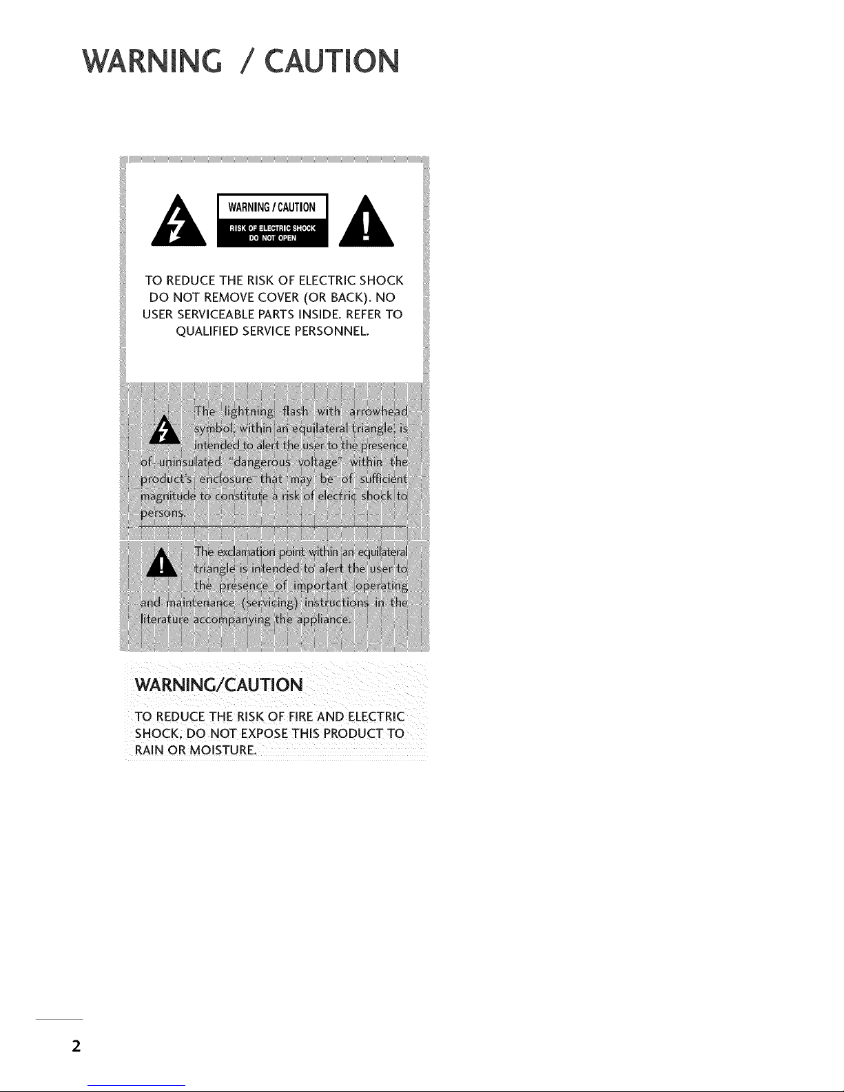
WARNING / CAUTION
TO REDUCE THE RiSK OF ELECTRICSHOCK
DO NOT REMOVECOVER (OR BACK), NO
USERSERVICEABLEPARTSiNSiDE. REFERTO
QUALiFiED SERVICEPERSONNEL,
WARNING/CAUTION
TO REDUCE THE RISK OF FIRE AND ELECTRIC
SHOCK; DO NOT EXPOSE THIS PRODUCT TO
RAIN OR MOISTURE:
SAFETYINSTRUCTIONS
IMPORTANT SAFETYINSTRUCTIONS
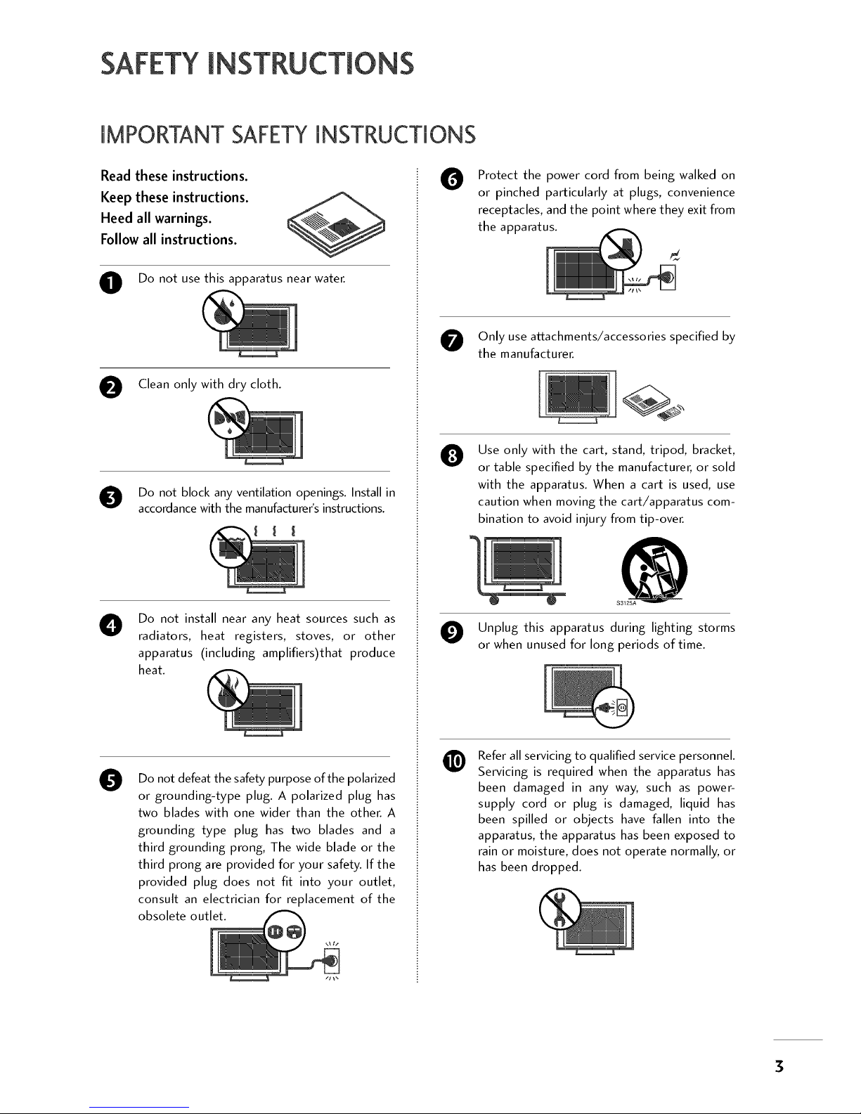
Read these instructions.
Keep these instructions.
Heed all warnings.
Follow all instructions.
O Do not use this apparatus near water.
O Clean only with dry cloth.
O Do not block any ventilation openings. Install in
accordance with the manufacturer's instructions.
O
Do not install near any heat sources such as
radiators, heat registers, stoves, or other
apparatus (including amplifiers)that produce
heat.
O
Do not defeat the safety purpose of the polarized
or grounding-type plug. A polarized plug has
two blades with one wider than the other. A
grounding type plug has two blades and a
third grounding prong, The wide blade or the
third prong are provided for your safety. If the
provided plug does not fit into your outlet,
consult an electrician for replacement of the
obsolete outlet.
O
Protect the power cord from being walked on
or pinched particularly at plugs, convenience
receptacles, and the point where they exit from
the apparatus.
O nly use attachments/accessories specified by
the manufacturer.
O
Use only with the cart, stand, tripod, bracket,
or table specified by the manufacturer, or sold
with the apparatus. When a cart is used, use
caution when moving the cart/apparatus com-
bination to avoid injury from tip-over.
O Unplug this apparatus during lighting storms
or when unused for long periods of time.
@
Refer all servicing to qualified service personnel.
Servicing is required when the apparatus has
been damaged in any way, such as power-
supply cord or plug is damaged, liquid has
been spilled or objects have fallen into the
apparatus, the apparatus has been exposed to
rain or moisture, does not operate normally, or
has been dropped.
SAFETYINSTRUCTIONS
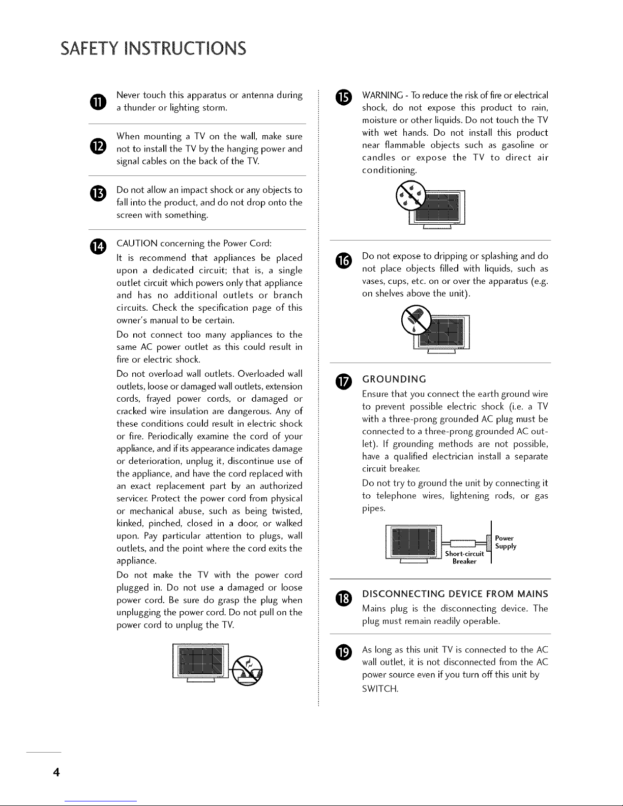
Never touch this apparatus or antenna during
a thunder or lighting storm.
0
®
0
When mounting a TV on the wall, make sure
not to install the TV by the hanging power and
signal cables on the back of the TV.
Do not allow an impact shock or any objects to
fall into the product, and do not drop onto the
screen with something.
CAUTION concerning the Power Cord:
It is recommend that appliances be placed
upon a dedicated circuit; that is, a single
outlet circuit which powers only that appliance
and has no additional outlets or branch
circuits. Check the specification page of this
owner's manual to be certain.
Do not connect too many appliances to the
same AC power outlet as this could result in
fire or electric shock.
Do not overload wall outlets. Overloaded wall
outlets, loose or damaged wall outlets, extension
cords, frayed power cords, or damaged or
cracked wire insulation are dangerous. Any of
these conditions could result in electric shock
or fire. Periodically examine the cord of your
appliance, and if its appearance indicates damage
or deterioration, unplug it, discontinue use of
the appliance, and have the cord replaced with
an exact replacement part by an authorized
servicer. Protect the power cord from physical
or mechanical abuse, such as being twisted,
kinked, pinched, closed in a door, or walked
upon. Pay particular attention to plugs, wall
outlets, and the point where the cord exits the
appliance.
Do not make the TV with the power cord
plugged in. Do not use a damaged or loose
power cord. Be sure do grasp the plug when
unplugging the power cord. Do not pull on the
power cord to unplug the TV.
0
@
0
0
@
WARNING - To reduce the risk of fire or electrical
shock, do not expose this product to rain,
moisture or other liquids. Do not touch the TV
with wet hands. Do not install this product
near flammable objects such as gasoline or
candles or expose the TV to direct air
conditioning.
Do not expose to dripping or splashing and do
not place objects filled with liquids, such as
vases, cups, etc. on or over the apparatus (e.g.
on shelves above the unit).
GROUNDING
Ensure that you connect the earth ground wire
to prevent possible electric shock (i.e. a TV
with a three-prong grounded AC plug must be
connected to a three-prong grounded AC out-
let). If grounding methods are not possible,
have a qualified electrician install a separate
circuit breaker.
Do not try to ground the unit by connecting it
to telephone wires, lightening rods, or gas
pipes.
Short-circuit
Breaker
Power
Supply
DISCONNECTING DEVICE FROM MAINS
Mains plug is the disconnecting device. The
plug must remain readily operable.
As long as this unit TV is connected to the AC
wall outlet, it is not disconnected from the AC
power source evenif you turn offthis unit by
SWITCH.
4
@
O
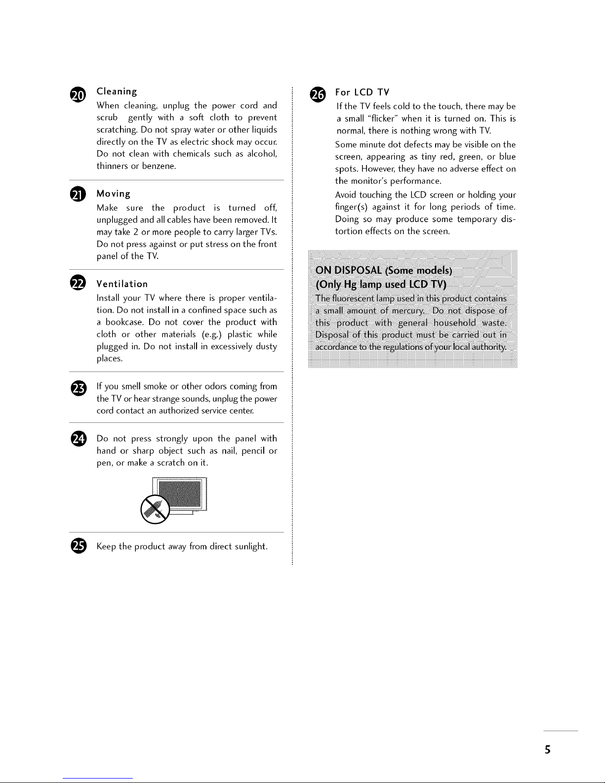
Cleaning
When cleaning, unplug the power cord and
scrub gently with a soft cloth to prevent
scratching. Do not spray water or other liquids
directly on the TV as electric shock may occur.
Do not clean with chemicals such as alcohol,
thinners or benzene.
Moving
Make sure the product is turned off,
unplugged and all cables have been removed. It
may take 2 or more people to carry larger TVs.
Do not press against or put stress on the front
panel of the TV.
Ventilation
Install your TV where there is proper ventila-
tion. Do not install in a confined space such as
a bookcase. Do not cover the product with
cloth or other materials (e.g.) plastic while
plugged in. Do not install in excessively dusty
places.
If you smell smoke or other odors coming from
the TV or hear strange sounds, unplug the power
cord contact an authorized service center.
Do not press strongly upon the panel with
hand or sharp object such as nail, pencil or
pen, or make a scratch on it.
Keep the product away from direct sunlight.
For LCD TV
If the TV feels cold to the touch, there may be
a small "flicker" when it is turned on. This is
normal, there is nothing wrong with TV.
Some minute dot defects may bevisible on the
screen, appearing as tiny red, green, or blue
spots. However,they haveno adverseeffect on
the monitor's performance.
Avoid touching the LCD screenor holding your
finger(s) against it for long periods of time.
Doing so may produce some temporary dis-
tortion effects on the screen.
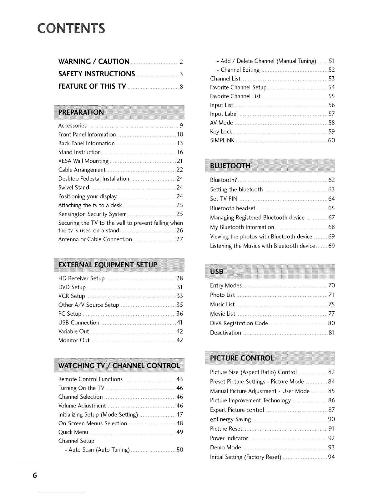
CONTENTS
Accessories ...................................................... 9
Front Panel Information ................................... lO
Back Panel Information .................................... 13
Stand Instruction ............................................. 16
VESA Wall Mounting ........................................ 21
Cable Arrangement ......................................... 22
Desktop Pedestal Installation ........................... 24
Swivel Stand ................................................... 24
Positioning your display ................................... 24
Attaching the tv to a desk ................................ 25
Kensington Security System ............................. 25
Securing the TV to the wall to prevent falling when
the tv is used on a stand ................................. 26
Antenna or Cable Connection .......................... 27
- Add / Delete Channel (Manual Tuning) ...... 51
- Channel Editing ........................................ 52
Channel List.................................................... 53
Favorite Channel Setup .................................... 54
Favorite Channel List ....................................... 55
Input List ........................................................ 56
Input Label ..................................................... 57
AV Mode ........................................................ 58
Key Lock......................................................... 59
SIMPLINK....................................................... 60
Bluetooth? ........................................................
Setting the bluetooth ...................................... 63
Set TV PIN ..................................................... 64
Bluetooth headset ........................................... 65
Managing Registered Bluetooth device ............. 67
My Bluetooth Information ............................... 68
Viewing the photos with Bluetooth device ........ 69
Listening the Musics with Bluetooth device ....... 69
HD Receiver Setup ......................................... 28
DVD Setup...................................................... 31
VCR Setup ..................................................... 33
Other A/V Source Setup ................................. 35
PC Setup ........................................................ 36
USB Connection ............................................. 41
VariableOut ................................................... 42
Monitor Out ................................................... 42
Entry Modes ................................................... 70
Photo List ....................................................... 71
Music List ....................................................... 75
Movie List ....................................................... 77
DivX Registration Code ................................... 80
Deactivation ................................................... 81
Remote Control Functions ............................... 43
Turning On the TV .......................................... 46
Channel Selection ........................................... 46
Volume Adjustment ......................................... 46
Initializing Setup (Mode Setting) ...................... 47
On-Screen Menus Selection ............................ 48
Quick Menu .................................................... 49
Channel Setup
- Auto Scan (Auto Tuning) ........................... 50
Picture Size (Aspect Ratio) Control .................. 82
Preset Picture Settings - Picture Mode ............. 84
Manual Picture Adjustment - User Mode .......... 85
Picture Improvement Technology ..................... 86
Expert Picture control ..................................... 87
e_ Energy Saving ............................................. 90
Picture Reset ................................................... 91
Power Indicator ............................................... 92
Demo Mode ................................................... 93
Initial Setting (Factory Reset) ........................... 94
6
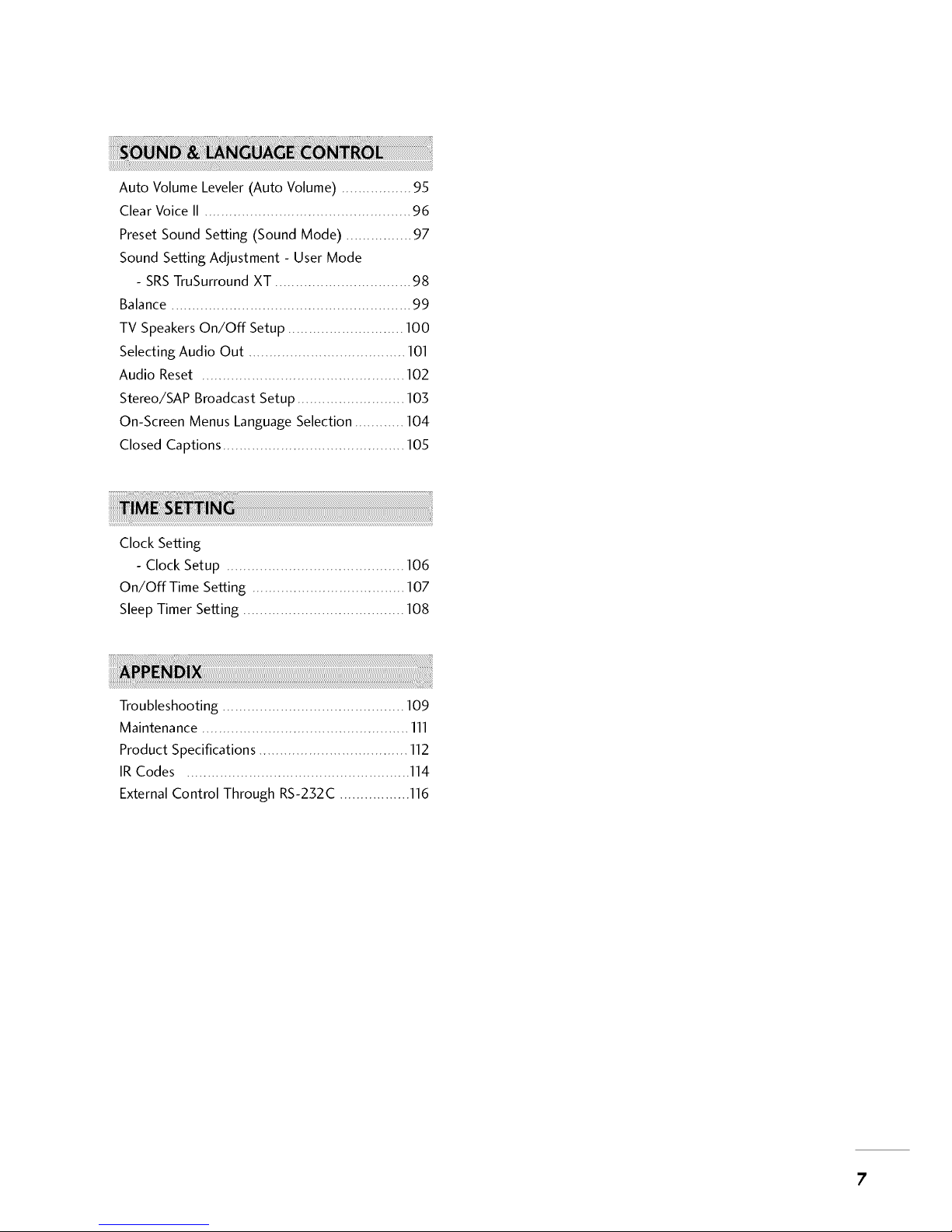
Auto Volume Leveler (Auto Volume) ................. 95
Clear Voice II .................................................. 96
Preset Sound Setting (Sound Mode) ................ 97
Sound Setting Adjustment - User Mode
- SRSTruSurround XT ................................. 98
Balance .......................................................... 99
TV SpeakersOn/Off Setup ............................ 100
Selecting Audio Out ...................................... 101
Audio Reset ................................................. 102
Stereo/SAP Broadcast Setup .......................... 103
On-Screen Menus LanguageSelection ............ 104
Closed Captions ............................................ 105
Clock Setting
- Clock Setup ........................................... 106
On/Off Time Setting ..................................... 107
SleepTimer Setting ....................................... 108
Troubleshooting ............................................ 109
Maintenance .................................................. 111
Product Specifications .................................... 112
IR Codes ...................................................... 114
ExternalControl Through RS-232C ................. 116
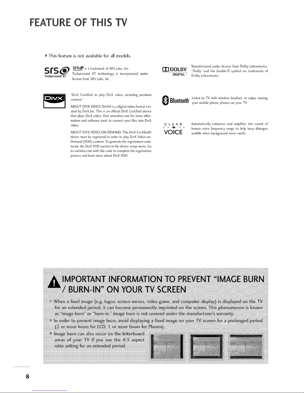
FEATUREOF THIS TV
This feature is not available for all models.
SrS_ S fSo_is a trad .... k of SRS Labs, Inc.
TruSurrouncl XT technology is incorporated under
TruSurround XT
license from SRS Labs, Inc.
[I] DOLB¥
DIGITAL ]
Manufactured under license from Dolby Laboratories.
"Dolby "and the double-D symbol are trademarks of
Dolby Laboratories.
"DivX Certified to play DivX video, including premium
content"
ABOUT DIVX VIDEO: DivX® is a digital video format cre-
ated by DivX,Inc. This is an official DivX Certified device
that plays DivX video. Visit www.divx.com for more infor-
mation and software tools to convert your files into DivX
video.
ABOUT DIVXVIDEO-ON-DEMAND: ThisDivX Certified®
devicemust be registered in order to play DivX Video-on-
Demand(VOD) content. To generatethe registration code,
locatethe DivXVOD section in the devicesetup menu.Go
to vod.divx.comwith this code to completethe registration
processandlearn more about DivX VOD.
Listen to TV with wireless headset,or enjoy viewing
Bluet00th'_y..... bile phone phot.... your TV.
C L E A R Automatically enhances and amplifies the sound of
human voice frequency range to help keep dialogue
VOICE audible when backg .... d noi ..... IIs.
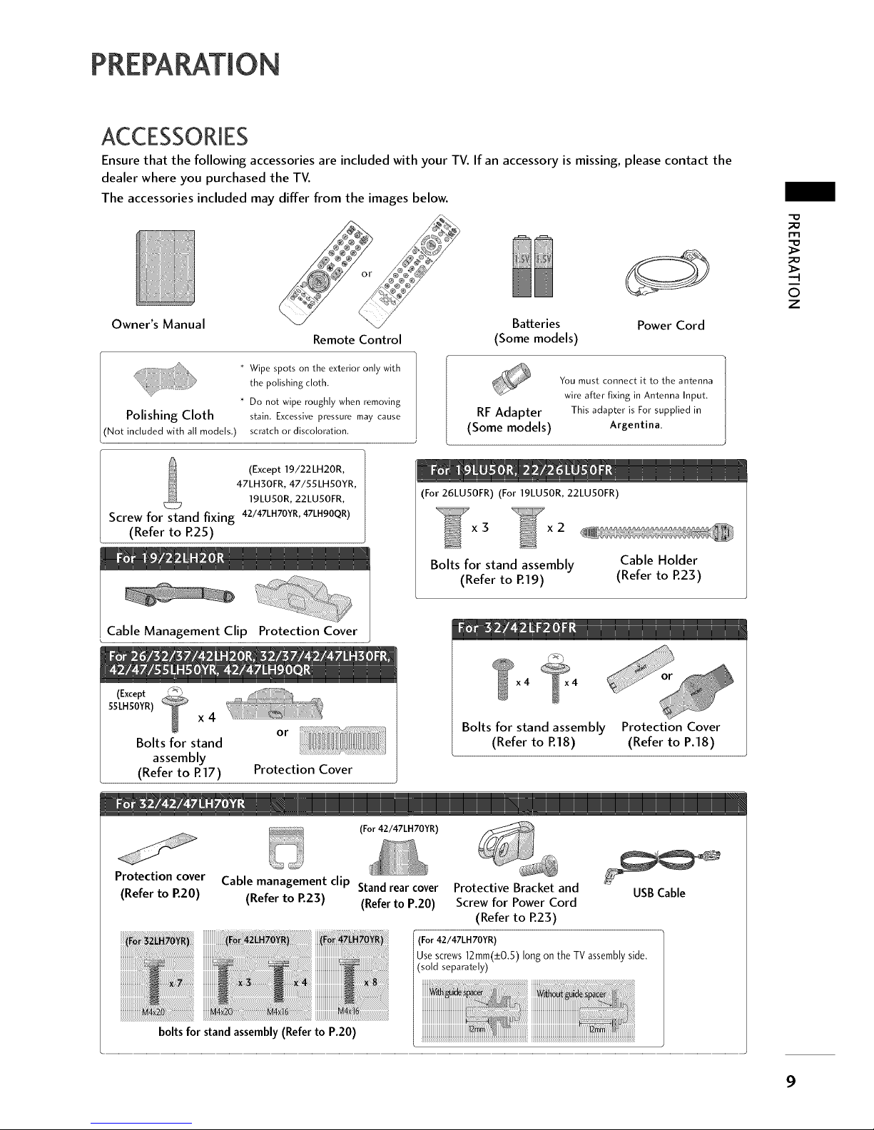
PREPARATION
Ensure that the following accessories are included with your TV. If an accessory is missing, please contact the
dealer where you purchased the TV.
The accessories included may differ from the images below.
Owner's Manual Batteries
Remote Control (Some models)
* Wipe spots on the exterior only with
the polishing cloth.
* Do not wipe roughly when removing
Polishing Cloth stain. Excessive pressure may cause
included with all models.) scratch or discoloration.
Power Cord
RF Adapter
(Some models)
You must connect it to the antenna
wire after fixing in Antenna Input.
This adapter is For supplied in
Argentina.
-o
©
z
(Except 19/22LH20R,
47LH30FR,47/55 LHSOYR,
19LU50R,22LU50FR,
Screw for stand fixing 42/47LHTOYR,47LH90QR)
(Refer to R25)
Cable Management Clip Protection Cover
(Except _"
SSLHSOYR)
x 4
Bolts for stand
assembly
(Refer to R17)
or
Protection Cover
(For 26LU50FR) (For 19LU50R, 22LU50FR)
x3 x2
Bolts for stand assembly
(Refer to R19)
Cable Holder
(Refer to P.23)
_L
Bolts for stand assembly Protection Cover
(Refer to R18) (Refer to P.18)
(For 42/47LH70YR)
Protection cover
(Refer to P.20)
Cable management clip Stand rear cover Protective Bracket and USB Cable
(Refer to P.23) (Refer to P.20) Screw for Power Cord
(Refer to R23)
(For42/47LH 70YR)
Use screws 12mm(_+0,5) long on the TV assemblyside.
(sold separately)
boltsfor stand assembly (Refer to P.20)
PREPARATION
-D
m
-q
©
z
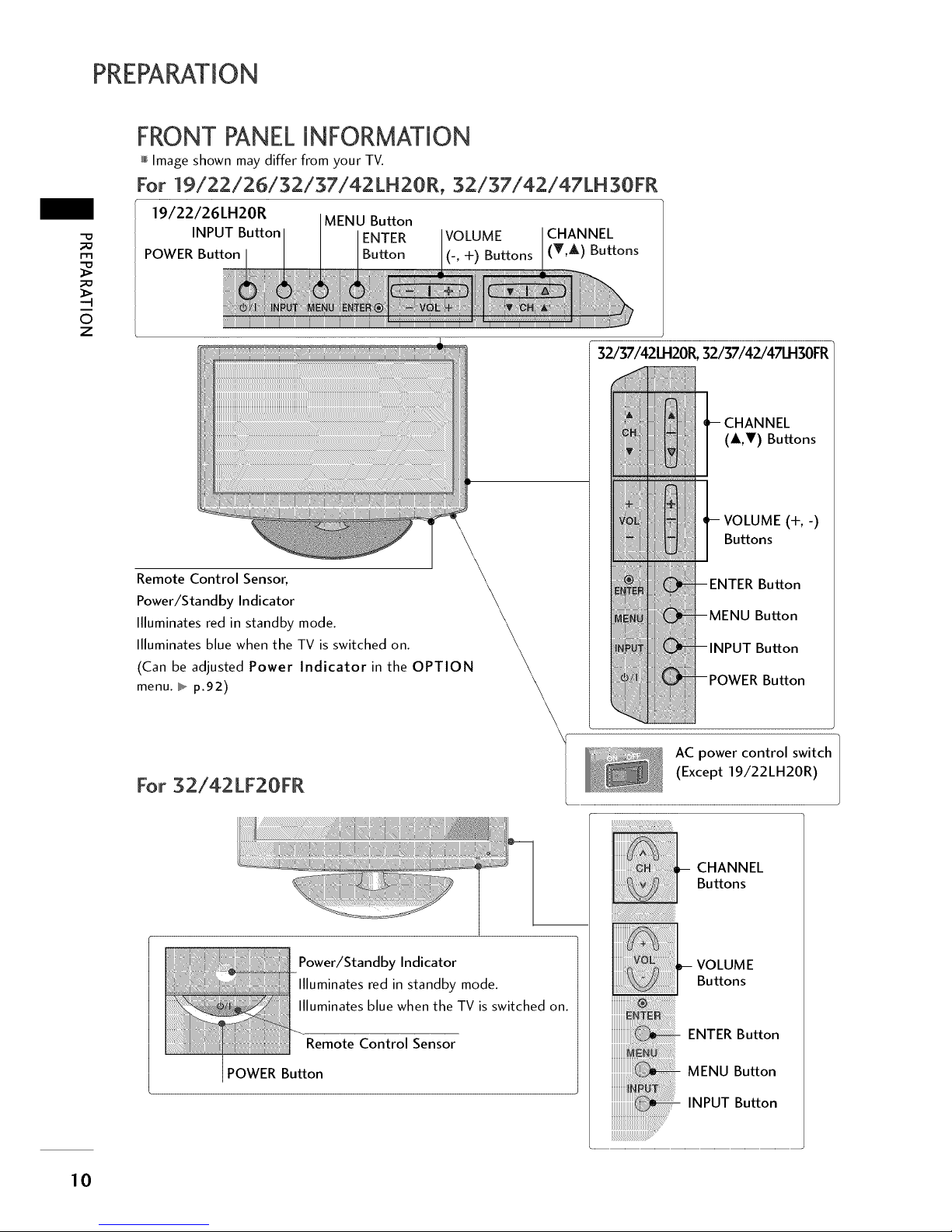
FRONT PANELINFORMATION
Image shown may differ from your TV.
For 19/22/26/32/37/42 LH2OR, 32/37/42/47LH 30FR
19/22/26LH20R MENU Button
INPUT Button ENTER VOLUME CHANNEL
POWER Button Button (-, +) Buttons (T,A) Buttons
Remote Control Sensor,
Power/Standby Indicator
Illuminates red in standby mode.
Illuminates blue when the TV is switched on.
(Can be adjusted Power Indicator in the OPTION
menu. I,_.p.92)
32./37/42LH201_32/37/42./47LH30FR
(&,V) Buttons
VOLUME (+,-)
Buttons
Button
Button
Button
Button
For 32/42LF20FR
Power/Standby Indicator
llluminates red in standby mode.
llluminates blue when the TV is switched on.
Remote Control Sensor
POWER Button
\r AC power control switch
(Except 19/22LH20R)
::_H : : CHANNEL
_Buttons
10

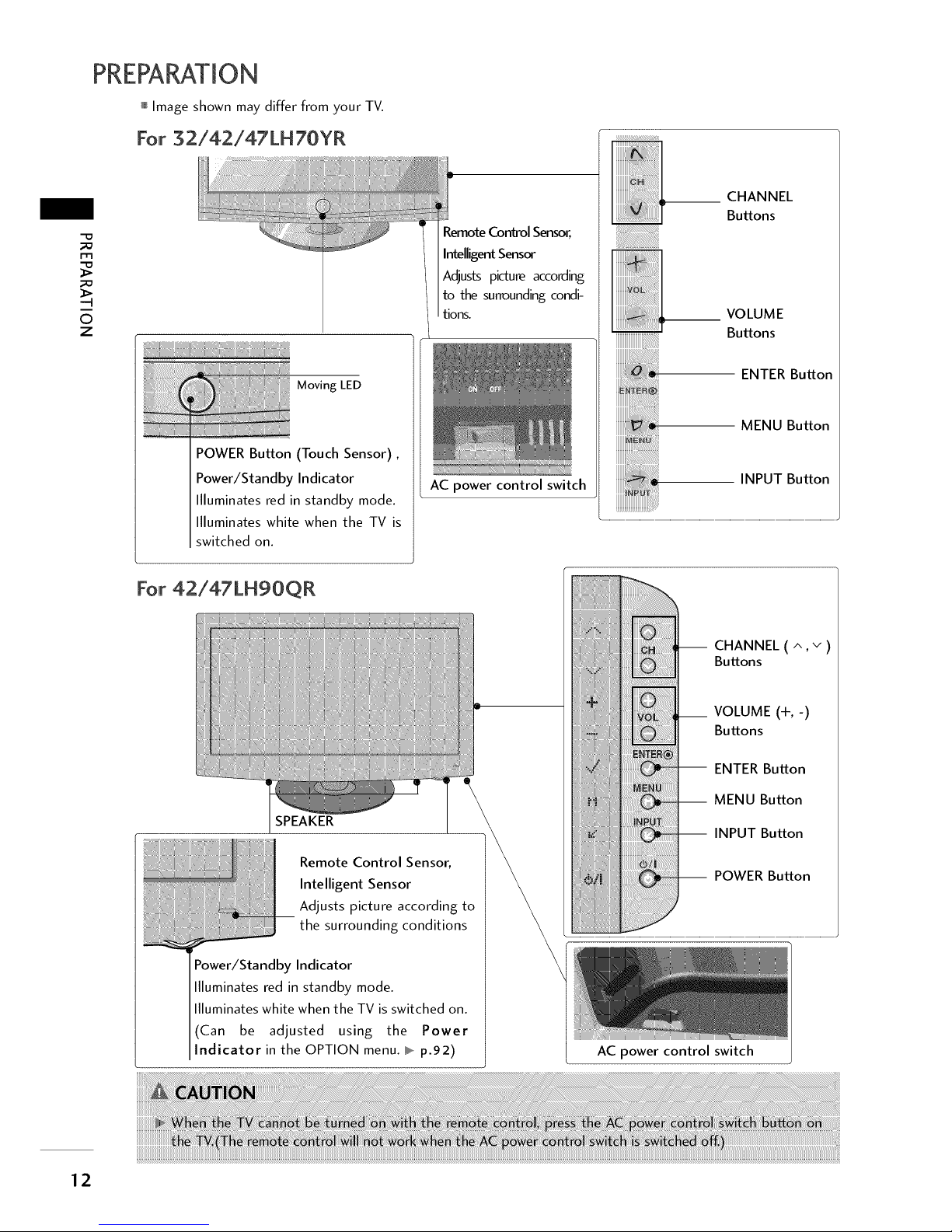
mImage shown may differ from your TV.
For 42/47/55 LH5OYR
Remote Control
Sensor
Intelligent Sensor
Adjusts picture
accordingto the sur-
rounding conditions.
Power/Standby Indicator
+
Illuminates red in standby mode.
llluminatesbluewhentheTV isswitchedon.
AC power control
switch
__CHANNEL
Buttons
--VOLUME
Buttons
--ENTER Button
--MENU Button
--INPUT Button
--POWER Button
For 19LU50R, 22LU50FR, 25LU50FR
19LUS0R,22LUS0FR
INPUT Button
POWER Button
MENU Button
ENTER Button
VOLUME
(-, +) Buttons
CHANNEL
(v ^) Buttons
--4
O
Z
SPEAKER
Remote Control Sensor
Power/Standby Indicator
Illuminates red in standby mode.
Illuminates white when the TV is
switched on.
26LUS0FR
__CHANNEL(^,v)
Buttons
__ VOLUME (+, -)
Buttons
-- ENTER Button
-- MENU Button
-- INPUT Button
-- POWER Button
AC power control
switch
11
PREPARATION
Image shown may differ from your TV.
For 32/42/47LH70YR
-o
m
6
z
Moving LED
POWER Button (Touch Sensor),
Power/Standby Indicator
Illuminates red in standby mode.
Illuminates white when the TV is
switched on.
Remote Control Sensor,
Intelligent Sensor
Adjusts picture according
to the surrounding condi-
tions.
AC power control switch
__ HANNEL
Buttons
_ 1-- VOLUMEButtons
E_ ENTER Button
MENU Button
INPUT Button
For 42/47LH90QR
SPEAKER
_ emote Control Sensor,
Intelligent Sensor
Adjusts picture according to
the surrounding conditions
Power/Standby Indicator
Illuminates red in standby mode.
llluminates white when the TV is switched on.
(Can be adjusted using the Power
ndicator in the OPTION menu. I_,,_p.92)
-- CHANNEL (^,v)
Buttons
VOLUME (+,-)
Buttons
-- ENTER Button
-- MENU Button
-- INPUT Button
-- POWER Button
AC power control switch
12
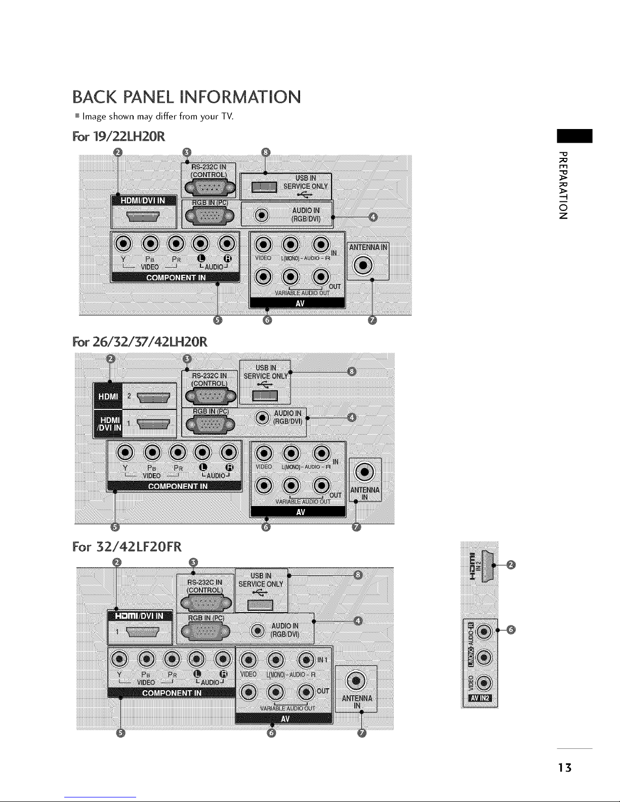
BACK PANEL INFORMATION
Image shown may differ from your TV.
For 19/22LH20R
-D
m
©
z
For 26/32/37/42LH20R
For 32/42LF20FR
13
PREPARATION
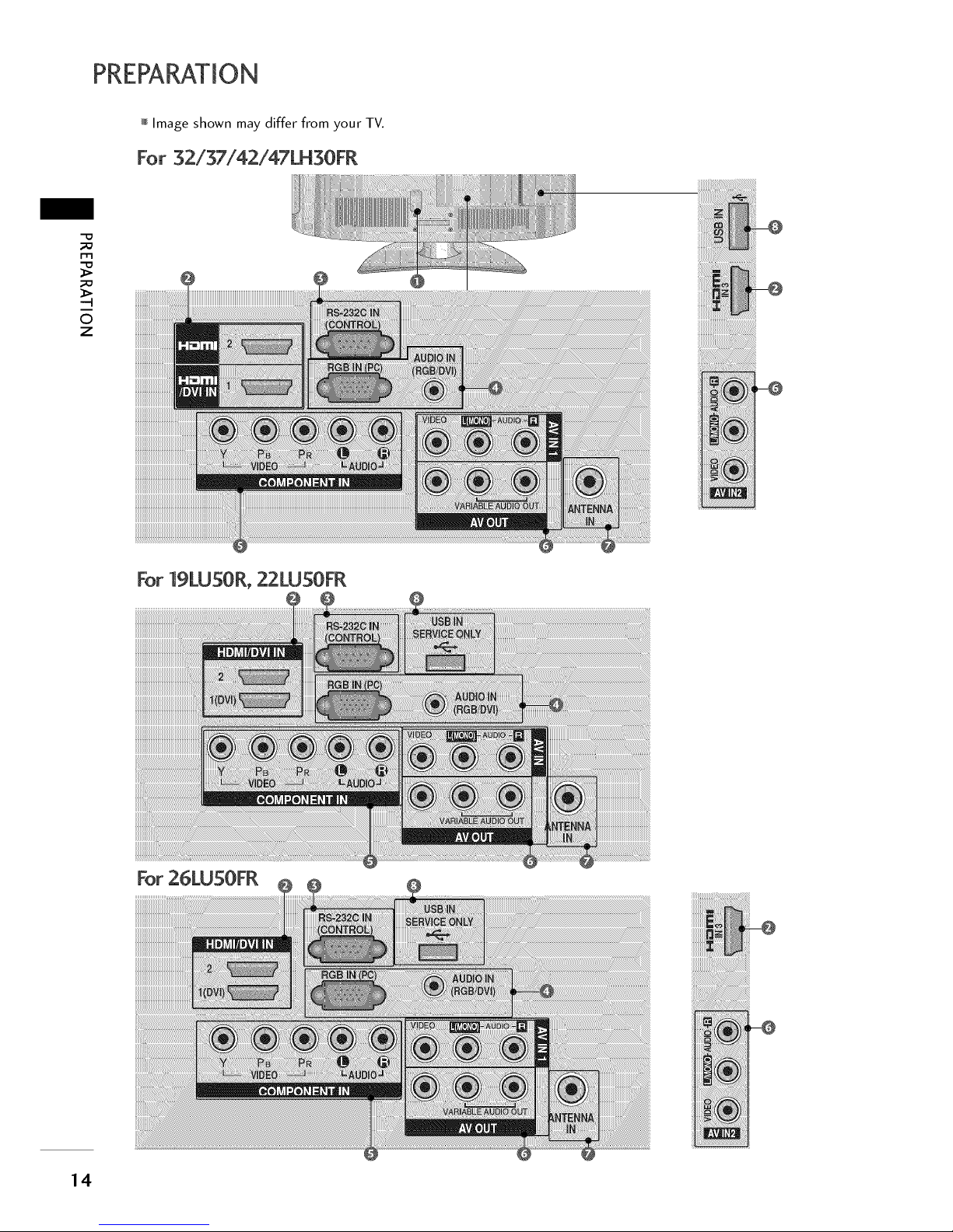
Image shown may differ from your TV.
For 32/37/42/47LH30FR
"D
m
--4
0
Z
For 19LU50R, 22LU50FR
14
For 26LU50FR
mImage shown may differ from your TV.
For 32/42/47LH70YR
-D
m
-4
0
Z
For 42/47/55LH50YR, 42/47LH90QR
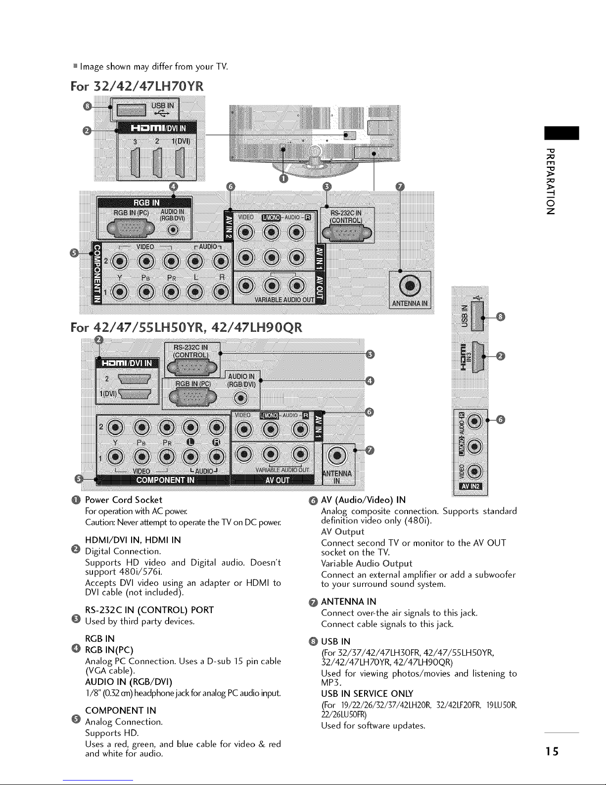
@ Power Cord Socket O
For operation with AC power.
Caution: Never attempt to operate the TV on DC power.
HDMI/DVI IN, HDMI IN
@ Digital Connection.
Supports HD video and Digital audio. Doesn't
support 480i/576i.
Accepts DVl video using an adapter or HDMI to
DVl cable (not included).
RS-232C IN (CONTROL) PORT
@ Used by third party devices.
@
RGB IN
RGB IN(PC)
Analog PC Connection. Uses a D-sub 15 pin cable
(VGA cable).
AUDIO IN (RGB/DVI)
1/8" (0.32 an) headphone jack for analog PC audio input.
@
COMPONENT IN
@ Analog Connection.
Supports HD.
Uses a red, green, and blue cable for video & red
and white for audio.
I ISI!II!!
AV (Audio/Video) IN
Analog composite connection. Supports standard
definition video only (480i).
AV Output
Connect second TV or monitor to the AV OUT
socket on the TV.
Variable Audio Output
Connect an external amplifier or add a subwoofer
to your surround sound system.
ANTENNA IN
Connect over-the air signals to this jack.
Connect cable signals to this jack.
USB IN
(For 32/37/42/47LH30FR, 42/47/55LH50YR,
32/42/47LH70YR, 42/47LHgOQR)
Used for viewing photos/movies and listening to
MP3.
USB IN SERVICE ONLY
(For 19/22/26/32/37/42LH20R, 32/42LF20FK 19LU50K
22/26LU50FR)
Used for software updates.
15
PREPARATION
'-D
-.I
©
z
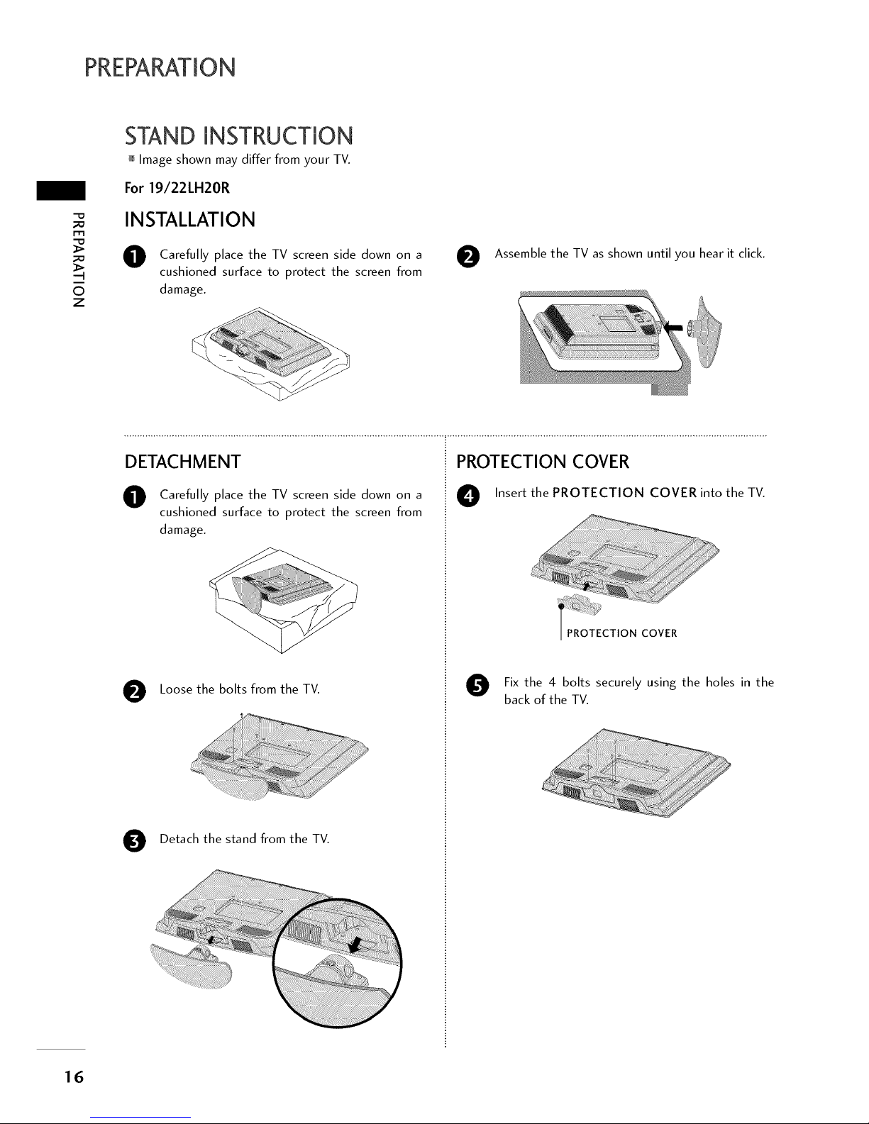
STAND INSTRUCTION
Image shown may differ from your TV.
For 19/22LH20R
INSTALLATION
O Carefully place the TV screen side down on a
cushioned surface to protect the screen from
damage.
O
Assemble the TV as shown until you hear it click.
DETACHMENT
O Carefully place the TV screen side down on a
cushioned surface to protect the screen from
damage.
O Loose the bolts from the TV.
O Detach the stand from the TV.
PROTECTION COVER
O Insert the PROTECTION COVER into the TV.
/ PROTECTIONCOVER
O Fix the 4 bolts securely using the holes in the
back of the TV.
16
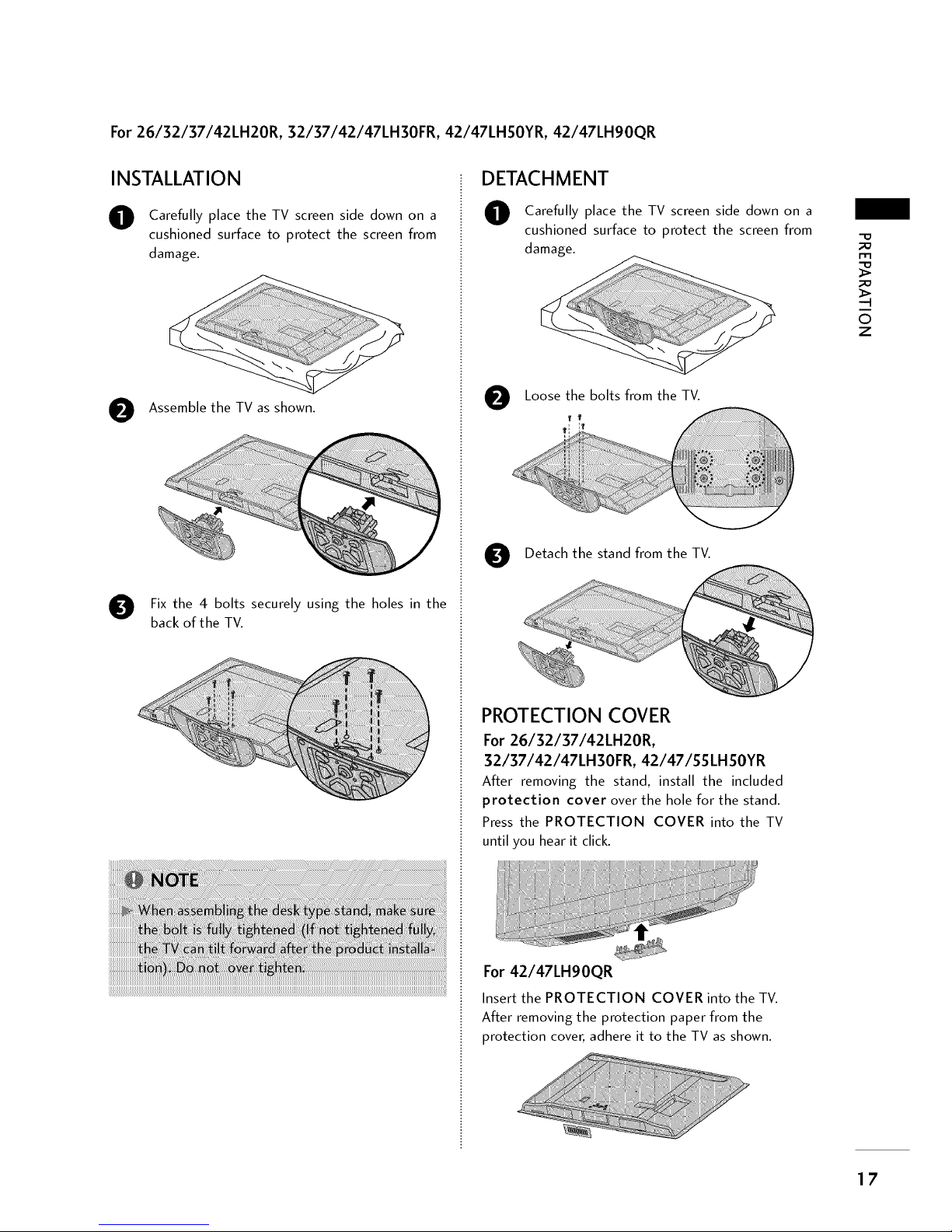
For26/32/37/42LH20R, 32/37/42/47LH30FR, 42/47LHSOYR, 42/47LH90QR
INSTALLATION
O
O
Carefully place the TV screen side down on a
cushioned surface to protect the screen from
damage.
Assemble the TV as shown.
Fix the 4 bolts securely using the holes in the
back of the TV.
DETACHMENT
O
O
Carefully place the TV screen side down on a
cushioned surface to protect the screen from
damage.
Loose the bolts from the TV.
Detach the stand from the TV.
PROTECTION COVER
For 26/32/37/42LH20R,
32/37/42/47LH30FR, 42/47/$$LH$OYR
After removing the stand, install the included
protection cover over the hole for the stand.
Press the PROTECTION COVER into the TV
until you hear it click.
For 42/47LH90QR
Insert the PROTECTION COVER into the TV.
After removing the protection paper from the
protection cover, adhere it to the TV as shown.
-q
©
Z
17

PREPARATION
m
_o
-q
O
z
For32/42LF20FR
INSTALLATION
Carefully place the TV screen side down on a
cushioned surface to protect the screen from
damage.
f+ ",,, ,,,,,
,,,\ ,.....
Assemble the STAND BODY to the STAND
BASE with the included screws.
BODY
Assemble the TV as shown.
BASE
Fix the 4 bolts securely using the holes in the
back of the TV.
DETACHMENT
O Carefully place the TV screen side down on a
cushioned surface to protect the screen from
damage.
O
Loose the bolts from the TV.
O Detach the stand from the TV.
PROTECTION COVER
After removing the stand, install the included
protection cover over the hole for the
stand.
Press the PROTECTION COVER into the TV
until you hear it click.
18
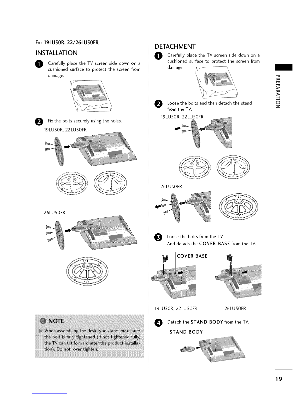
For 19LUSOR, 22/26LUSOFR
INSTALLATION
O Carefully place the TV screen side down on a
cushioned surface to protect the screen from
damage.
O Fix the bolts securely using the holes.
19LU50R, 22LU50FR
26LU50FR
DETACHMENT
O Carefully place the TV screen side down on a
cushioned surface to protect the screen from
damage.
O Loose the bolts and then detach the stand
from the TV.
19LU50R, 22LU50FR
26LU50FR
Loose the bolts from the TV.
And detach the COVER BASE from the TV.
COVER BASE
19LU50R, 22LU50FR 26LU50FR
O Detach the STAND BODY from the TV.
STAND BODY
-D
m
-q
©
z
19
PREPARATION
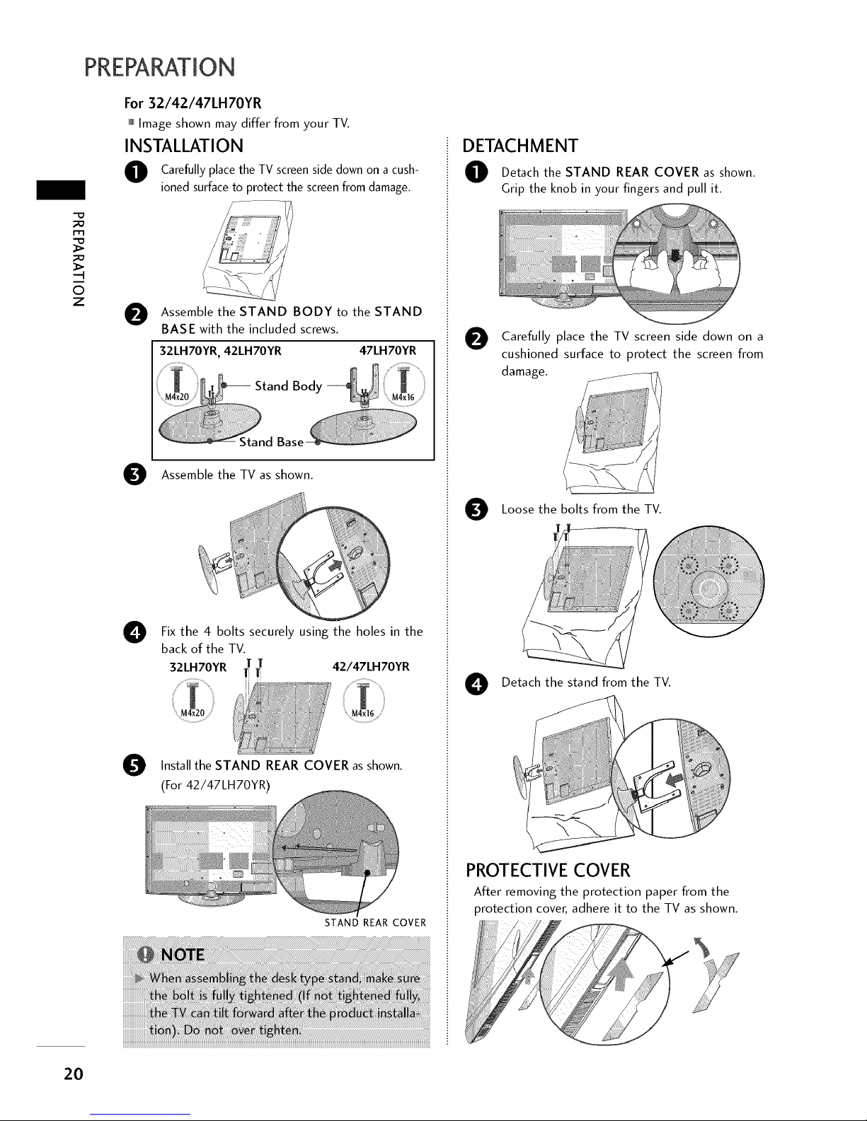
For 32/42/47LH70YR
Image shown may differ from your TV.
INSTALLATION
O Carefully place the TV screenside down on a cush-
ioned surfaceto protect the screenfrom damage.
-4
©
Z
O
Assemble the STAND BODY to the STAND
BASE with the included screws.
32LH70YR, 42LH70YR 47LH70YR
O
O
Assemble the TV as shown.
Fix the 4 bolts securely using the holes in the
back of the TV.
T 42/47LH70YR
32LH70YR T
M4x20
STAND REAR COVER as
Install the shown.
(For 42/47LH70YR)
STAND REAR COVER
DETACHMENT
O Detach the STAND REAR COVER shown.
as
Grip the knob in your fingers and pull it.
O Carefully place the TV screen side down on a
cushioned surface to protect the screen from
damage.
O Loose the bolts from the TV.
O Detach the stand from the TV.
PROTECTIVE COVER
After removing the protection paper from the
protection cover, adhere it to the TV as shown.
2O
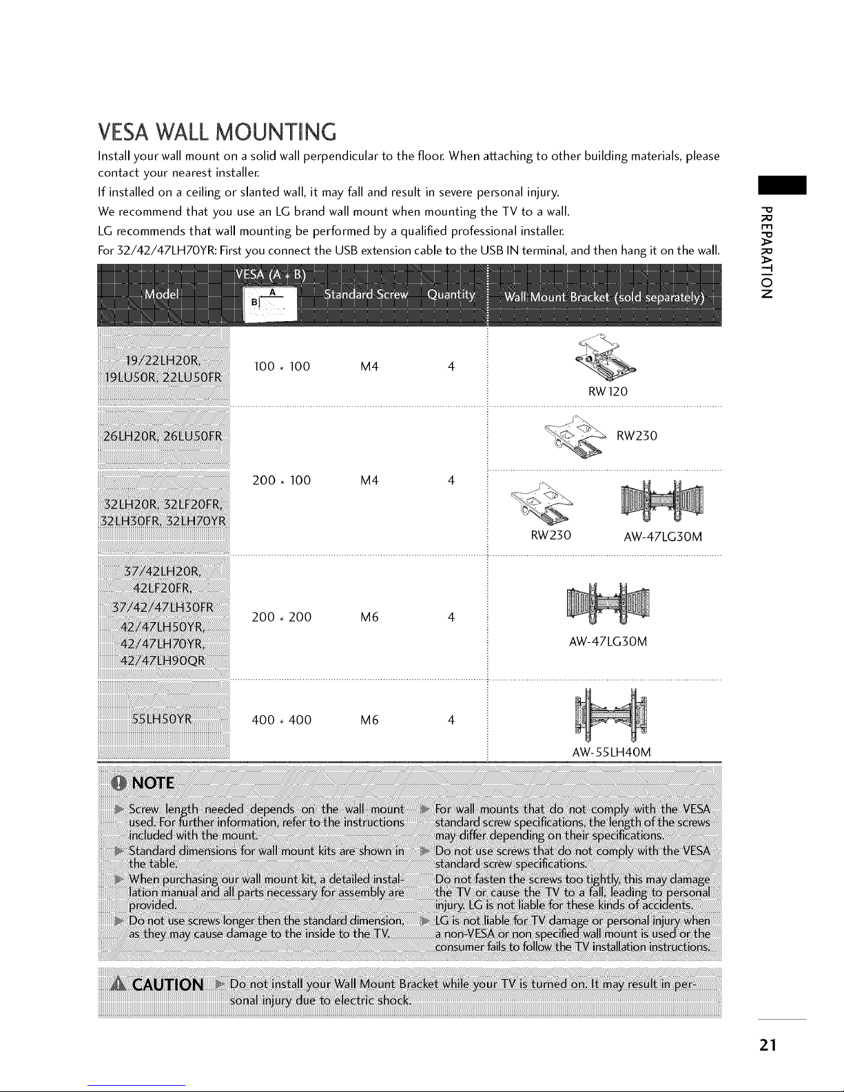
VESAWALL MOUNTMNG
Install your wall mount on a solid wall perpendicular to the floor. When attaching to other building materials, please
contact your nearest installer.
If installed on a ceiling or slanted wall, it may fall and result in severe personal injury.
We recommend that you use an LG brand wall mount when mounting the TV to a wall.
LG recommends that wall mounting be performed by a qualified professional installer.
For 32/42/47LH70YR: First you connect the USB extension cable to the USB IN terminal, and then hang it on the wall.
-D
m
;X3
-q
©
z
RW23 0 AW-47 LG3 0 M
..............................................................................................................................................................................................
200. 200 M6 4
AW-47LG30M
400. 400 M6 4
AW-55LH40M
21
PREPARATION
m
-q
©
z
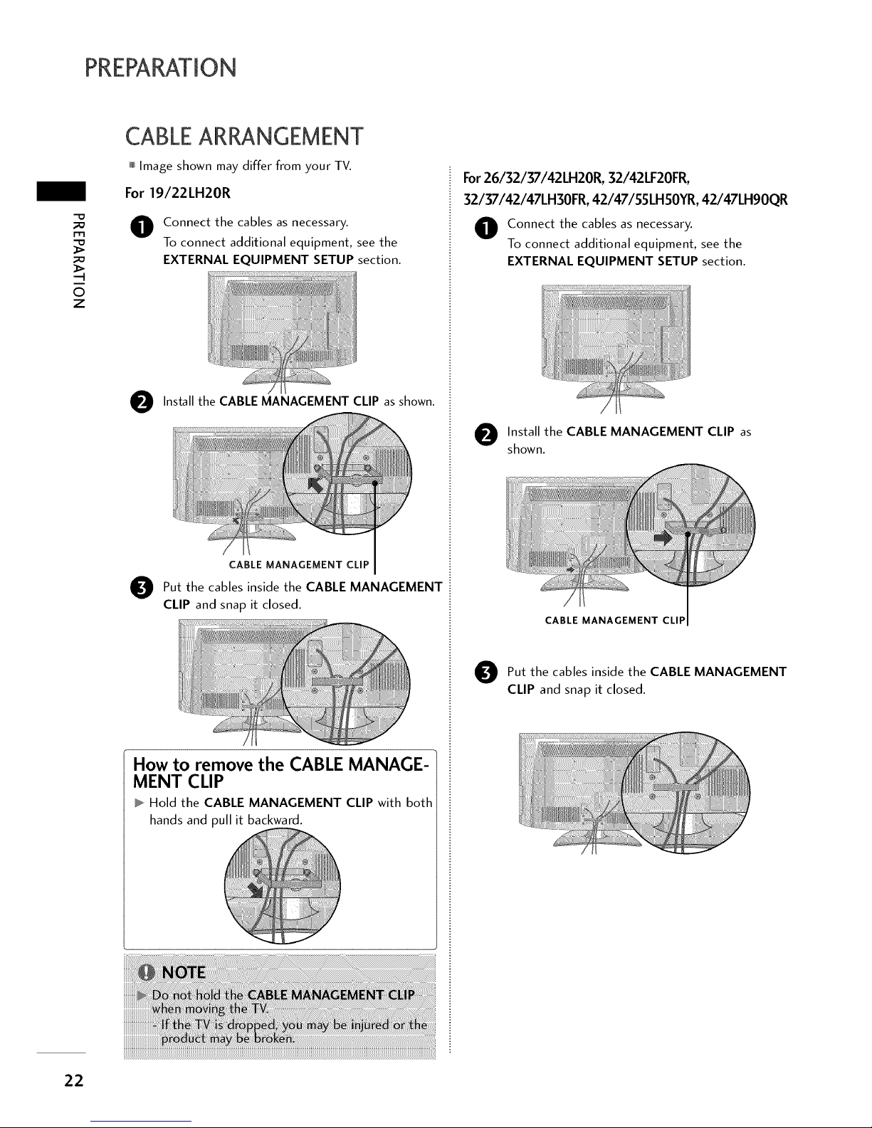
CABLEARRANGEMENT
Image shown may differ from your TV.
For 19/22LH20R
O onnect the cables as necessary.
To connect additional equipment, see the
EXTERNAL EQUIPMENT SETUP section.
O Install the CABLE MANAGEMENT CLIP as shown.
CABLEMANAGEMENTCLiP
O ut the cables inside the CABLE MANAGEMENT
CLIP and snap it closed.
How to remove the CABLE MANAGE-
MENT CLIP
Hold the CABLE MANAGEMENT CLIP with both
hands and pull it backward.
For26/32/37/42LH20R, 32/42LF20FR,
32/37/42/47LH30FR,42/47/55LHSOYR,42/47LH90QR
O onnect the cables as necessary.
To connect additional equipment, see the
EXTERNAL EQUIPMENT SETUP section.
O nstall the CABLE MANAGEMENT CLIP as
shown.
CABLE MANAGEMENT CLIP
O ut the cables inside the CABLE MANAGEMENT
CLIP and snap it closed.
22
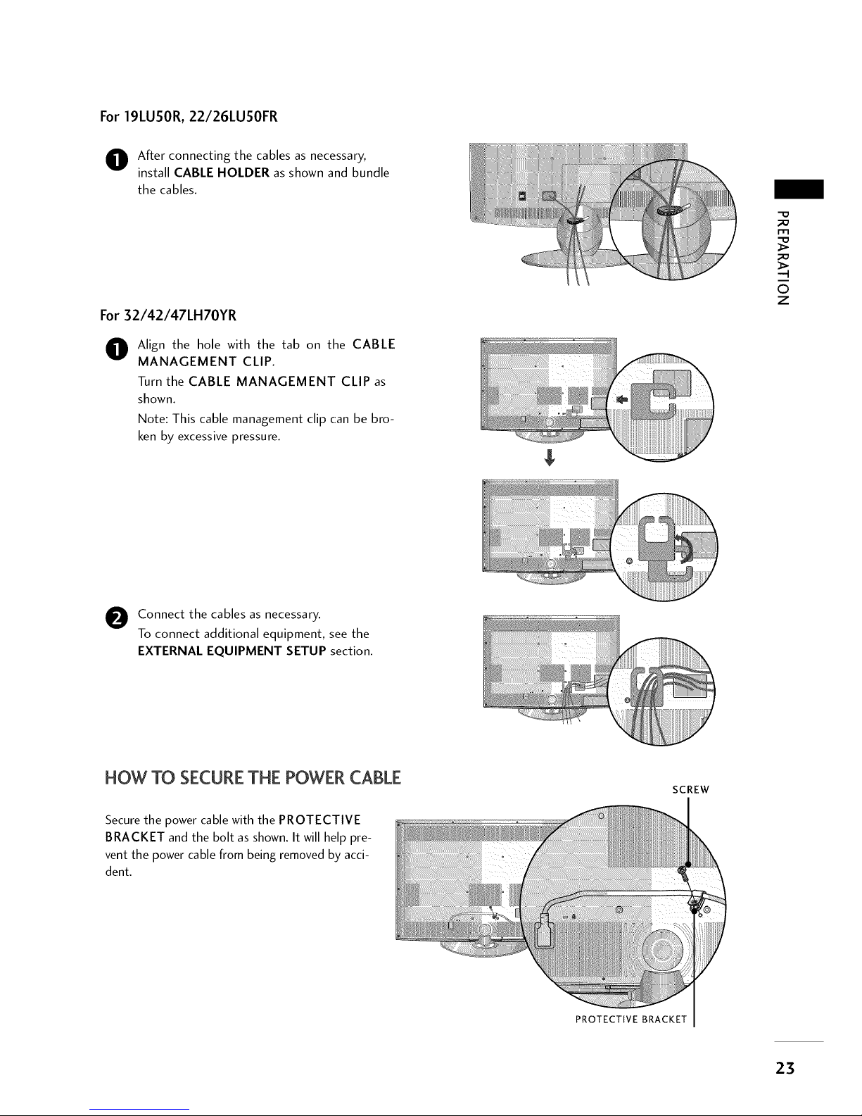
For19LUSOR,22/26LUSOFR
O fter connecting the cables as necessary,
install CABLE HOLDER as shown and bundle
the cables.
For 32/42/47LH70YR
O lign the hole with the tab on the CABLE
MANAGEMENT CLIP.
Turn the CABLE MANAGEMENT CLIP as
shown.
Note: This cable management clip can be bro-
ken by excessive pressure.
-O
_o
-q
©
z
O onnect the cables as necessary.
To connect additional equipment, see the
EXTERNAL EQUIPMENT SETUP section.
FlOW TO SECURE THE POWER CABLE
Secure the power cable with the PROTECTIVE
BRACKET and the bolt as shown. It will help pre-
vent the power cable from being removed by acci-
dent.
SCREW
PROTECTIVE BRACKET
23
PREPARATION
DESKTOP PEDESTALINSTALLATION
-D
m
-q
O
z
Image shown may differ from your TV.
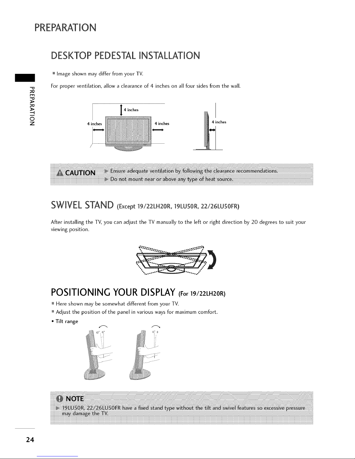
For proper ventilation, allow a clearance of 4 inches on all four sides from the wall.
4 inches
4 inches 4 inches
4 inches
SWIVELSTAND (Except ]9/22LH20R, ]gLUSOR, 22/26LU5OFR)
After installing the TV, you can adjust the TV manually to the left or right direction by 20 degrees to suit your
viewing position.
%
\
POSITIONING YOUR DISPLAY(For |9/22LH20R)
Here shown may be somewhat different from your TV.
Adjust the position of the panel in various ways for maximum comfort.
• Tilt range
12 O__ 07 3
i
..... oi._
24
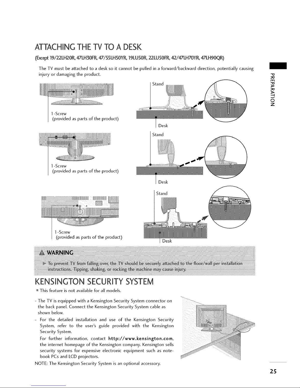
ATTACHINGTHE TV TO A DESK
(Except19/22LH20R,47LH30FR,47/55LHSOYR,19LUSOR,22LUSOFR,42/47LH70YR,47LH90QR)
The TV must be atLached to a desk so it cannot be pulled in a forward/backward direction, potentially causing
injury or damaging the product.
1-Screw
(provided as parts of the product)
1-Screw
(provided as parts of the product)
1-Screw
(provided as parts of the product)
Desk
Stand
KENSINGTON SECURITYSYSTEM
Desk
Stand
Desk
-D
rll
>
©
z
This feature is not available for all models.
- The TV is equipped with a Kensington Security System connector on ?":_
the back panel. Connect the Kensington Security System cable as
shown below.
For the detailed installation and use of the Kensington Security
System, refer to the user's guide provided with the Kensington
Security System.
For further information, contact http://www.kensington.com,
the internet homepage of the Kensington company. Kensington sells
security systems for expensive electronic equipment such as note-
book PCs and LCD projectors.
NOTE: The Kensington Security System is an optional accessory.
25
PREPARATION
-D
m
>
-q
©
z
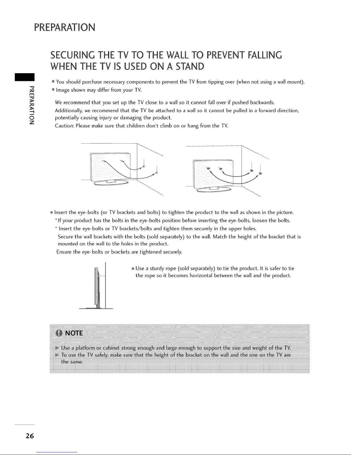
SECURMNGTHE TV TO THE WALL TO PREVENTFALLMNG
WHEN THE TV MSUSED ON A STAND
You should purchase necessary components to prevent the TV from tipping over (when not using a wall mount).
Image shown may differ from your TV.
We recommend that you set up the TV close to a wall so it cannot fall over if pushed backwards.
Additionally, we recommend that the TV be at2ached to a wall so it cannot be pulled in a forward direction,
potentially causing injury or damaging the product.
Caution: Please make sure that children don't climb on or hang from the TV.
i Insert the eye-bolts (or TV brackets and bolts) to tighten the product to the wall as shown in the picture.
* If your product has the bolts in the eye-bolts position before inserting the eye-bolts, loosen the bolts.
* Insert the eye-bolts or TV brackets/bolts and tighten them securely in the upper holes.
Secure the wall brackets with the bolts (sold separately) to the wall. Match the height of the bracket that is
mounted on the wall to the holes in the product.
Ensure the eye-bolts or brackets are tightened securely.
I Use a sturdy rope (sold separately) to tie the product. It is safer to tie
the rope so it becomes horizontal between the wall and the product.
26
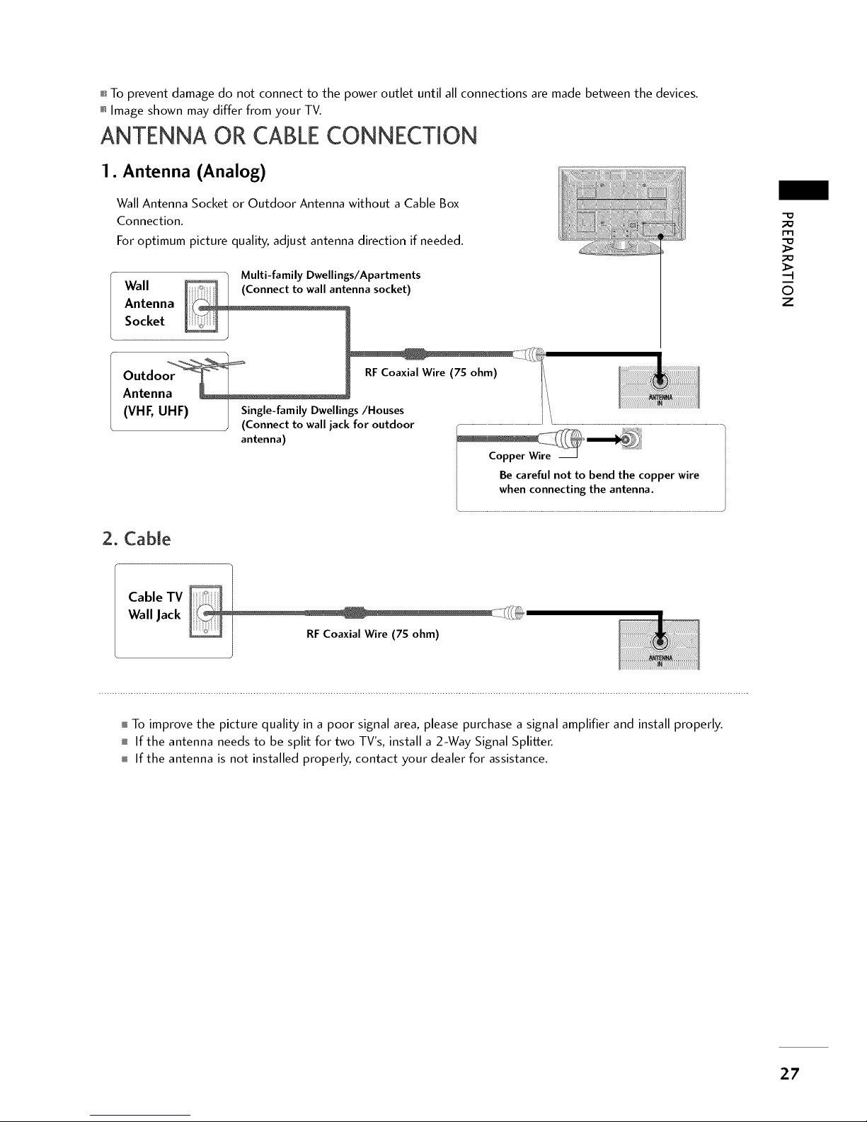
i To prevent damage do not connect to the power outlet until all connections are made between the devices.
Image shown may differ from your TV.
ANTENNA OR CABLECONNECTION
1. Antenna (Analog)
Wall Antenna Socket or Outdoor Antenna without a Cable Box
Connection.
For optimum picture quality, adjust antenna direction if needed.
Multi-family Dwellings/Apartments
Wall enna socket)
Antenna
Socket
Outdo RF Coaxial Wire (7S ohm) I_
Antenna i!i
(VHF, UHF) Single-family Dwellings/Houses
)
(Connect to wall jack for outdoor
antenna)
Be careful not to bend the copper wire
whenconnecting the antenna.
2. Cable
-O
m
..q
i
©
z
Cable TV
Wall Jack
RFCoaxial Wire (7S ohm)
I To improve the picture quality in a poor signal area, please purchase a signal amplifier and install properly.
i If the antenna needs to be split for two TV's, install a 2-Way Signal Splitter.
i If the antenna is not installed properly, contact your dealer for assistance.
27
EXTERNAL EQUIPMENT SETUP
To prevent the equipment damage, never plug in any power cords until you have finished connecting all equipment.
i This part of EXTERNAL EQUIPMENT SETUP mainly use picture for 2 6/3 2/3 7/42 LH2 OR.
HD RECEIVERSETUP
Component Connection
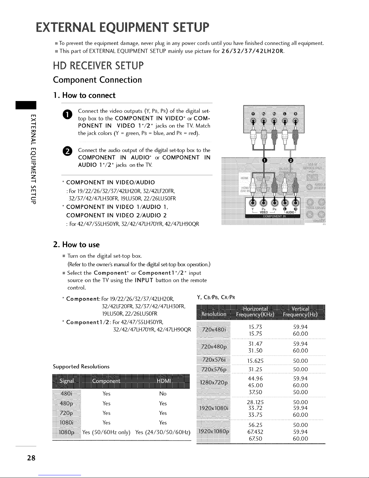
1. How to connect
x
m
_o
z
c
i
-O
z
c
"O
O
Connect the video outputs (Y, PB,PR)of the digital set-
top box to the COMPONENT IN VIDEO* or COM-
PONENT IN VIDEO 1"/2" jacks on the TV. Match
the jack colors (Y = green, PB= blue,and PR= red).
O Connect the audio output of the digital set-top box to the
COMPONENT IN AUDIO* or COMPONENT IN
AUDIO 1*/2" jacks on the TV.
* COMPONENT IN VIDEO/AUDIO
: For 19/22/26/32/37/42LH20R, 32/42LF20FR,
32/37/42/47LH30FR, 19LU50R, 22/26LU50FR
* COMPONENT IN VIDEO l/AUDIO 1,
COMPONENT IN VIDEO 2/AUDIO 2
: For42/47/55LH50YR, 32/42/47LH70YR, 42/47LH90QR
2. How to use
I Turn on the digital set-top box.
(Refer to the owner's manual for the digital set-top box operation.)
i Select the Component* or Component1*/2* input
source on the TV using the INPUT button on the remote
control.
* Component: For 19/22/26/32/37/42LH20R,
32/42 LF2OFR, 32/37/42/47LHgOFR,
19LU50R, 22/26LU50FR
* Co mponent 1/2: For 42/47/55LH50YR,
32/42/47LH70YR, 42/47LHgOQR
Y, CB/PB, CR/PR
Supported Resolutions
Yes No
Yes Yes
Yes Yes
Yes Yes
Yes (50/60Hz only) Yes(24/30/50/60Hz)
15.75 59.94
15.75 60.00
31.47 59.94
31.50 60.00
15.625 50.00
...............3.!:.2_..........................._o:Qo................
44.96 59.94
45.00 60.00
3Z50 50.00
28.125 50.00
35.72 59.94
33.75 60.00
56.25 50.00
6Z432 59.94
6Z50 60.00
28
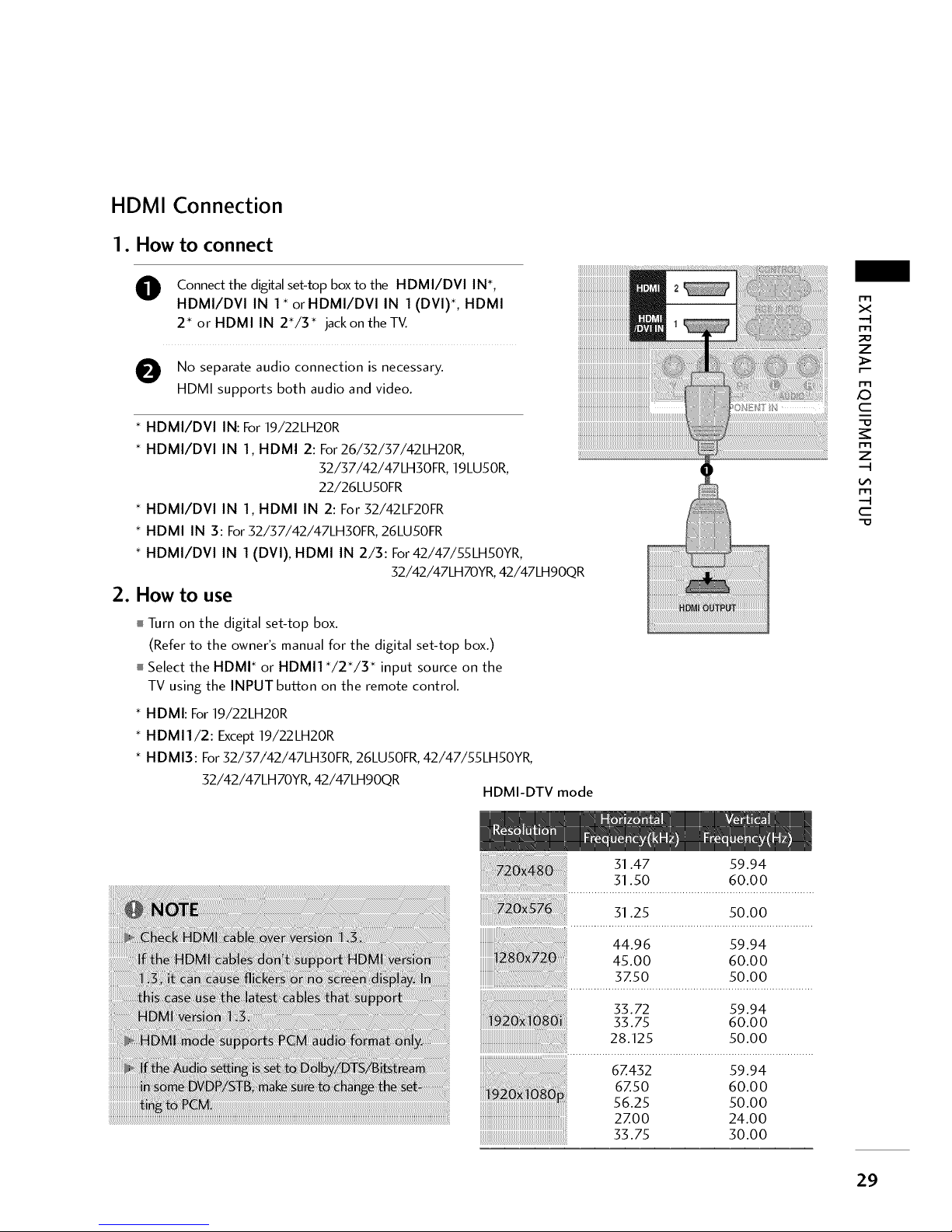
HDMI Connection
1. How to connect
O onnect the digital set4op box to the HDMI/DVI IN*,
HDMI/DVl IN 1" orHDMI/DVl IN 1 (DVl)*, HDMI
2* or HDMI IN 2"/3" jackon theTV.
O No separate audio connection is necessary.
HDMI supports both audio and video.
* HDMI/DVI IN: For 19/22LH20R
* HDMI/DVI IN 1, HDMI 2: For 26/32/37/42LH20R,
32/37/42/47LH30FR 19LU50R,
22/26LU50FR
* HDMI/DVI IN 1, HDMI IN 2: For 32/42LF20FR
* HDMI IN 3: For 32/37/42/47LH30FR, 26LU50FR
* HDMI/DVl IN 1 (DVl), HDMI IN 2/3: For 42/47/55LH50YR,
32/42/47LH70YR, 42/47LHgOQR
2. How to use
I Turn on the digital set-top box.
(Refer to the owner's manual for the digital set-top box.)
i Select the HDMI* or HDMI1 */2"/3 * input source on the
TV using the INPUT buRon on the remote control.
HDMI: For 19/22LH20R
HDMI1/2: Except 19/22LH20R
* HDMI3: For 32/37/42/47LH30FR, 26LU50FR, 42/47/55LH50YR,
32/42/47LH70YR, 42/47LHgOQR
HDMI-DTV mode
m
x
-4
m
7
m
c
-O
m
7
-H
m
-4
C
"O
31.47 59.94
31.50 60.00
31.25 50.00
44.96 59.94
45.00 60.00
3Z50 50.00
33.72 59.94
33.75 60.00
28.125 50.00
6Z432 59.94
6Z50 60.00
56.25 50.00
2ZOO 24.00
33.75 30.00
29
EXTERNALEQUIPMENT SETUP
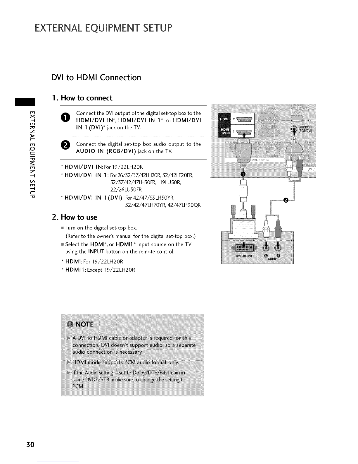
DVI to HDMI Connection
m
x
-q
m
z
m
c
-o
m
z
m
..q
c
"O
1. How to connect
O
Connect the DVI output of the digital set-top box to the
HDMI/DVI IN*, HDMI/DVI IN 1", or HDMI/DVI
IN 1 (DVI)* jack on the TV.
O Connect the digital set-top box audio output to the
AUDIO IN (RGB/DVI) jack on the TV.
* HDMI/DVl IN: For19/22LH20R
* HDMI/DVl IN 1: For26/52/57/42LH20K 52/42LF20FR,
52/57/42/47LHSOFR, 19LU50R,
22/26LU50FR
* HDMI/DVl IN 1 (DVl): For42/47/55LH50YR,
32/42/47LH70YR, 42/47LHgOQR
2. How to use
I Turn on the digital set-top box.
(Refer to the owner's manual for the digital set-top box.)
i Select the HDMI*, or HDMI1 * input source on the TV
using the INPUT button on the remote control.
• HDMI: For 19/22LH20R
• HDMIl:Except 19/22LH20R
3O
 Loading...