

LG 42LH90 Service Manual

1080P
Direct View LCD
Training
42LH90
42LH90
LED Backlights
Original February 09, 2010
Updated July
28, 2010

OUTLINE
OUTLINE
Preliminary Section:
Contact Information, Preliminary Matters, Specifications,
LCD Overview, General Troubleshooting Steps,
Signal Distribution, Disassembly Instructions and Voltages
Disassembly Section: Removal of Circuit Boards
Troubleshooting Section:
• Switch Mode Power Supply
• Inverter Board (LED Backlight Driver)
• T-CON (TFT Controller) Panel Driver board
• Main Board
• Ft Control Board
•
Side Keys
• Speakers
Board Operation Troubleshooting of :
2
February 2010
LCD DV 42LH90

Overview of Topics to be Discussed
Overview of Topics to be Discussed
42LH90 LCD Direct View Display
This Section will cover Contact Information and remind the Technician of Important Safety Precautions for
the Customers Safety as well as the Technician and the Equipment.
Basic Troubleshooting Techniques which can save time and money sometimes can be overlooked. These
techniques will also be presented.
Section 1
This Section will get the Technician familiar with the Disassembly, Identification and Layout of the LCD
Display Panel.
At the end of this Section the Technician should be able to Identify the Circuit Boards and have the ability
and knowledge necessary to safely remove and replace any Circuit Board or Assembly.
3
February 2010
LCD DV 42LH90

Preliminary Matters (The Fine Print)
Preliminary Matters (The Fine Print)
IMPORTANT SAFETY NOTICE
IMPORTANT SAFETY NOTICE
The information in this training manual is intended for use by persons possessing an adequate background in
electrical equipment, electronic devices, and mechanical systems. In any attempt to repair a major Product,
personal injury and property damage can result. The manufacturer or seller maintains no liability for the
interpretation of this information, nor can it assume any liability in conjunction with its use. When servicing this
product, under no circumstances should the original design be modified or altered without permission from LG
Electronics. Unauthorized modifications will not only void the warranty, but may lead to property damage or
user injury. If wires, screws, clips, straps, nuts, or washers used to complete a ground path are removed for
service, they must be returned to their original positions and properly fastened.
CAUTION
CAUTION
To avoid personal injury, disconnect the power before servicing this product. If electrical power is required for
diagnosis or test purposes, disconnect the power immediately after performing the necessary checks. Also be
aware that many household products present a weight hazard. At least two people should be involved in the
installation or servicing of such devices. Failure to consider the weight of an product could result in physical
injury.
4
February 2010
LCD DV 42LH90

(Electrostatic Static Discharge)
ESD Notice
ESD Notice
Today’s sophisticated electronics are electrostatic discharge (ESD) sensitive. ESD can weaken or damage
the electronics in a manner that renders them inoperative or reduces the time until their next failure.
Connect an ESD wrist strap to a ground connection point or unpainted metal in the product. Alternatively,
you can touch your finger repeatedly to a ground connection point or unpainted metal in the product. Before
removing a replacement part from its package, touch the anti-static bag to a ground connection point or
unpainted metal in the product. Handle the electronic control assembly by its edges only. When
repackaging a failed electronic control assembly in an anti-static bag, observe these same precautions.
Regulatory Information
Regulatory Information
This equipment has been tested and found to comply with the limits for a Class B digital device, pursuant to
Part 15 of the FCC Rules. These limits are designed to provide reasonable protection against harmful
interference when the equipment is operated in a residential installation. This equipment generates, uses,
and can radiate radio frequency energy, and, if not installed and used in accordance with the instruction
manual, may cause harmful interference to radio communications. However, there is no guarantee that
interference will not occur in a particular installation. If this equipment does cause harmful interference to
radio or television reception, which can be determined by turning the equipment off and on, the user is
encouraged to try to correct the interference by one or more of the following measures: Reorient or relocate
the receiving antenna; Increase the separation between the equipment and the receiver; Connect the
equipment to an outlet on a different circuit than that to which the receiver is connected; or consult the
dealer or an experienced radio/TV technician for help.
(Electrostatic Static Discharge)
5
February 2010
LCD DV 42LH90
LG Contact Information
LG Contact Information
Customer Service (and Part Sales) (800) 243-0000
Technical Support (and Part Sales) (800) 847-7597
USA Website (GSFS) http://gsfs-america.lge.com
Customer Service Website us.lgservice.com
LG Web Training lge.webex.com
LG CS Academy lgcsacademy.com
LCD-DV:
PLASMA:
PDP Panel Alignment Handbook, Schematics with Bookmarks
32LG40, 32LH30, 37LH55, 42LG60, 42LG70, 42LH20, 42LH40, 42LH50, 42LH90, 42SL80,
47LG90, 47LH85, 47LE8500
42PG20, 42PQ20, 42PQ30, 50PG20, 50PJ350, 50PK750, 50PS80, 50PS60, 60PK750,
60PS11, 60PS60, 60PS80
Also available on the Plasma Page:
Plasma Control Board ROM Update (Jig required)
Published February 2010 by LG Technical Support and Training
LG Electronics Alabama, Inc.
201 James Record Road, Huntsville, AL, 35813.
Presentations with Audio/Video
and Screen Marks
http://136.166.4.200
New Training Materials on
New Training Materials on
the Learning Academy site
the Learning Academy site
6
February 2010
LCD DV 42LH90

LCD Direct View Overview
LCD Direct View Overview
Safety and Handling Regulations
1. Approximately 20 minute pre-run time is required before making any picture performance
adjustments from the Menu.
2. Refer to the Voltage/Current silk screening on the Switch Mode Power Supply.
3. C-MOS circuits are sensitive to static electricity.
Use caution when dealing with these IC and circuits.
4. Exercise care when making voltage and waveform checks to prevent costly short circuits
from damaging the unit.
5. Be cautious of lost screws and other metal objects to prevent a possible short in the
circuitry.
Checking Points to be Considered
1. Check the appearance of the Replacement Panel and Circuit Boards for both physical
damage and part number accuracy.
2. Check the model label. Verify model names and board model matches.
3. Check details of defective condition and history. Example: Oscillator failure dead set, etc…
7
February 2010
LCD DV 42LH90
Basic Troubleshooting Steps
Basic Troubleshooting Steps
Define, Localize, Isolate and Correct
•Define
the failure. Use your senses Sight, Smell, Touch and Hearing. Look for burned parts and
check for possible overheated components. Capacitors will sometimes leak dielectric material
and give off a distinct odor. Frequency of power supplies will change with the load, or listen for
relay closing etc. Observation of the front Power LED may give some clues.
•Localize
checked and after giving a thorough examination using your senses the first check should
always be the DC Supply Voltages to those circuits under test. Always confirm the supplies
are not only the proper level but be sure they are noise free. If the supplies are missing check
the resistance for possible short circuits.
•Isolate
Oscilloscope to make a final determination of the failure. Look for correct Amplitude Phasing
and Timing of the signals also check for the proper Duty Cycle of the signals. Sometimes
“glitches” or “road bumps” will be an indication of an imminent failure.
Look at the symptom carefully and determine what circuits could be causing
After carefully checking the symptom and determining the circuits to be
To further isolate the failure, check for the proper waveforms with the
•Correct
check the DC Supplies for proper levels. Make all necessary adjustments and lastly always
perform a Safety AC Leakage Test before returning the product back to the Customer.
The final step is to correct the problem. Be careful of ESD and make sure to
8
February 2010
LCD DV 42LH90
42LH90 PRODUCT INFORMATION SECTION
42LH90 PRODUCT INFORMATION SECTION
This section of the manual will discuss the specifications of the
42LH90
LCD Direct View Display
9
February 2010
LCD DV 42LH90

Basic Specifications
Basic Specifications
Key TV Features
• LED Backlight with Local Dimming
• TruMotion 240Hz
• Intelligent Sensor
• Full HD 1080p
• 2,000,000:1 Contrast Ratio
• 2.4ms Response Time
• 500 cd/m² Brightness
• Wide Color gamut
• Super IPS Panel
• XD Engine
• 24fps Real Cinema
• ISFccc Ready
• Picture Wizard
• AV Mode II (Cinema, Sports, Game)
• Audio Output Power 10W x 2
• Invisible Speaker system
• Clear Voice II
• SRS TruSurround XT™
• Smart Volume Controller
• Dolby® Digital 5.1 Decoder
• Backlight Control
• Video Mute
• ENERGY STAR® 3.0 Compliant
• 4 HDMI™ v1.3 with Deep Color
• SIMPLINK™ Connectivity
• 2 HD Component Video Inputs
• 2 Composite inputs
• 1 Digital Audio Out
• NTSC / ATSC / Clear QAM
• USB 2.0 (JPEG, MP3, MP4, Divx)
• PC Connectivity (D-Sub 15pin)
• RF Antenna Input
10
February 2010
LCD DV 42LH90

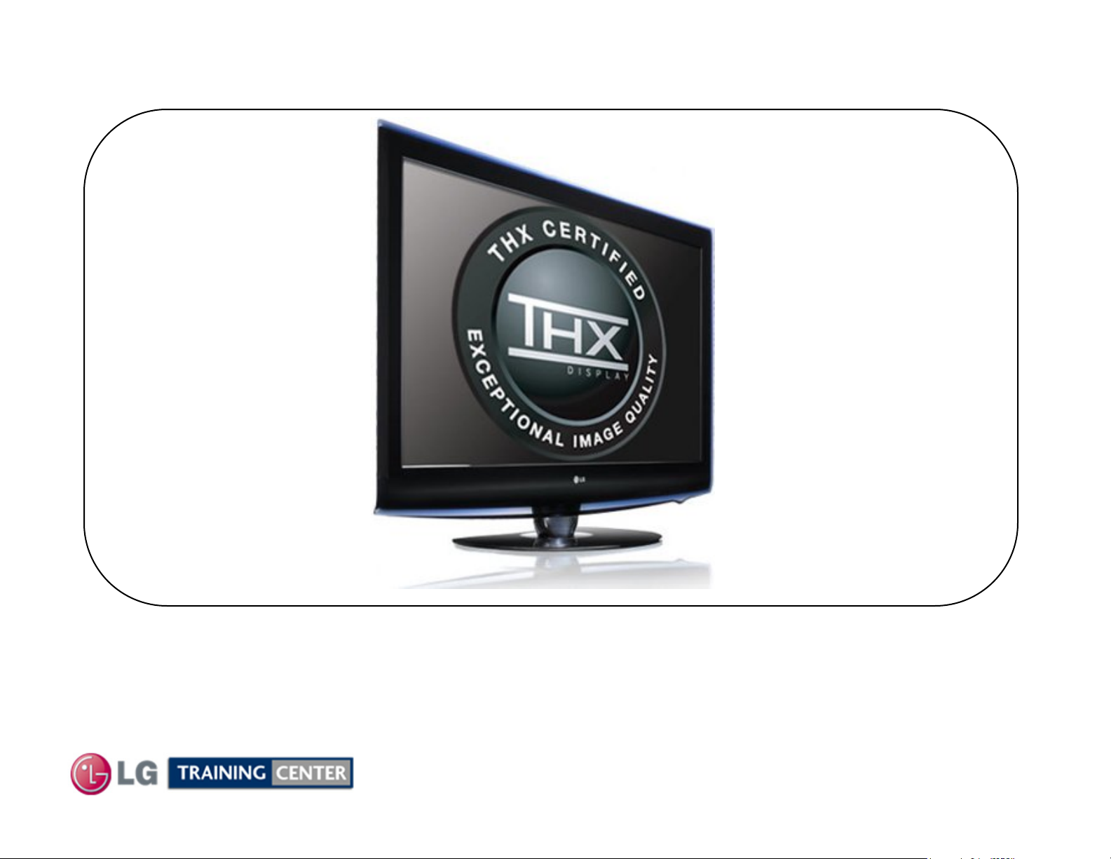
Basic Specifications (LOGO Familiarization)
Basic Specifications (LOGO Familiarization)
Full HD 1080p Resolution
Displays HDTV programs in full 1920 x 1080p resolution for a more detailed picture.
11
February 2010
LCD DV 42LH90
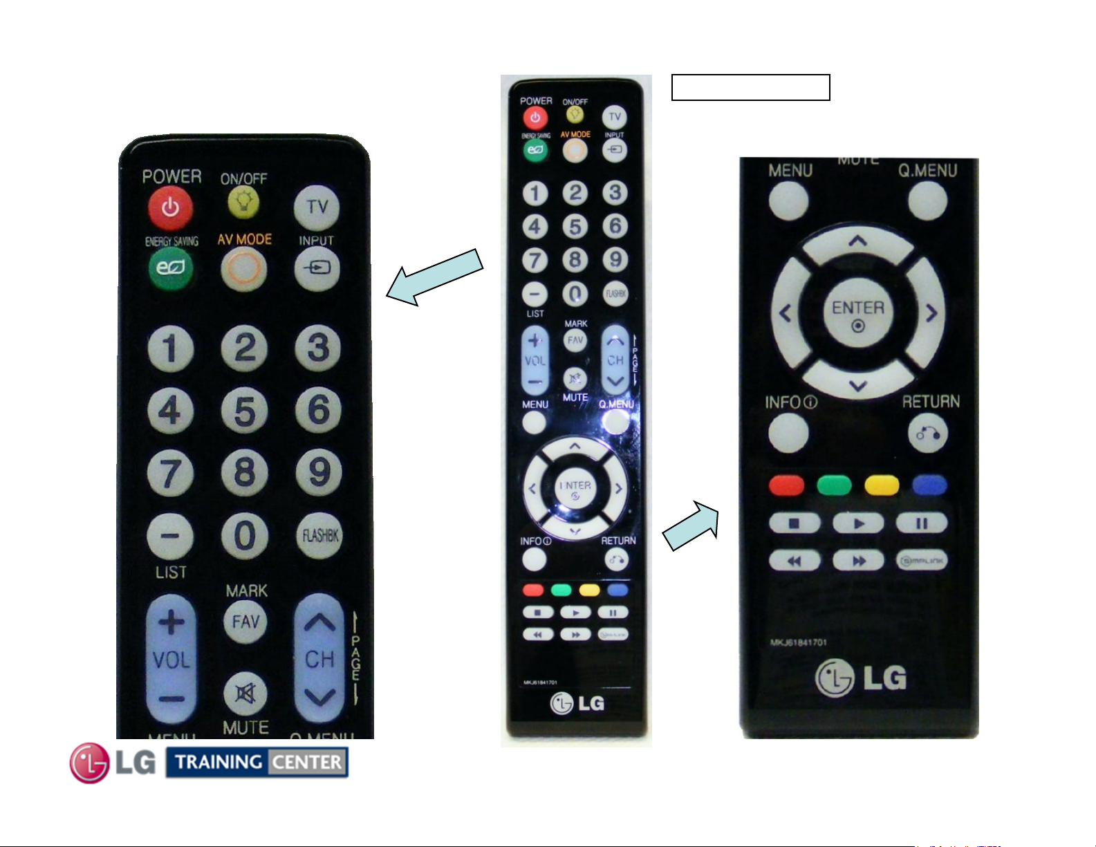
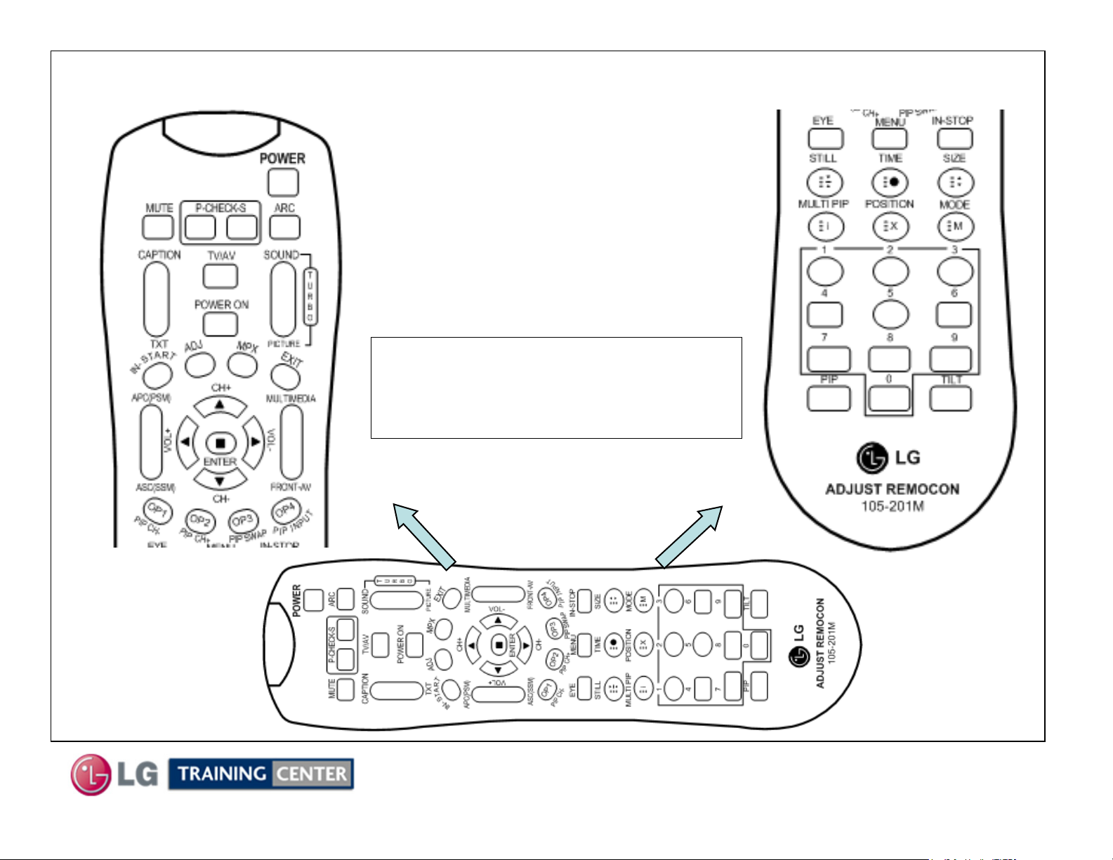
Remote Control Familiarization
Remote Control Familiarization
TOP PORTION
p/n MKJ61841701
BOTTOM PORTION
12
February 2010
LCD DV 42LH90
Accessing the Service Menu
Accessing the Service Menu
To access the Service Menu.
1) You must have the Service
2) Press “In-Start”
3) A Password screen appears.
Remote. p/n 105-201M
Note: A Password is required
to enter the Service Menu.
Enter; 0000
13
February 2010
LCD DV 42LH90
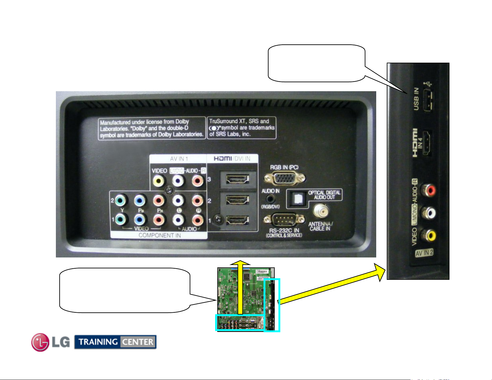
TV Rear Input / Output Jacks
TV Rear Input / Output Jacks
Rear In/Out Jacks
USB Port
Software Upgrades
Music, Photos
Side In/Out
MAIN BOARD
Rear and Side
Input/Output locations
14
February 2010
LCD DV 42LH90
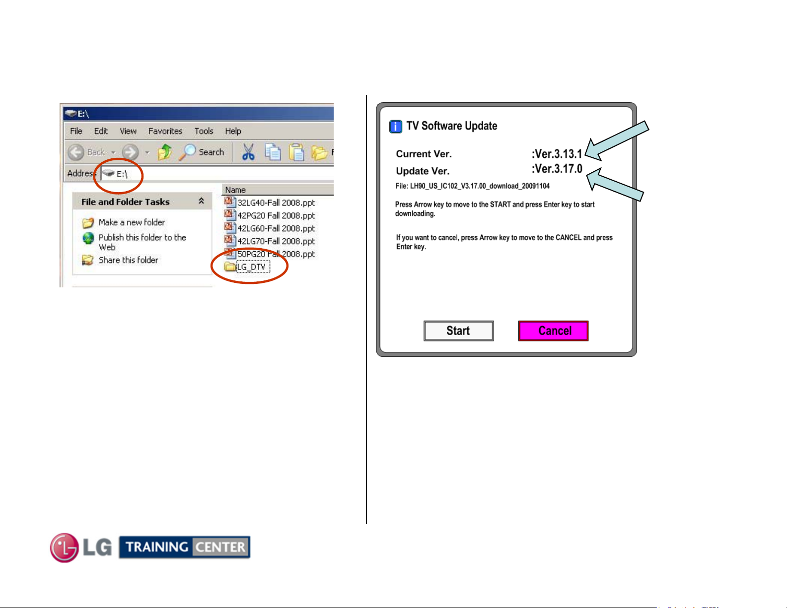
Software Download
Software Download
1) Create an LG_DTV folder on the USB Flash Drive
2) Copy new software (xxx.epk) to "LG_DTV"
folder. Make sure to have correct software file.
3) With TV turned on, insert USB flash drive.
4) You can see the message
“TV Software Upgrade” (See figure to right)
5) Cursor left and highlight "START" Button and
push “Enter” button using the remote control.
6) You can see the download progress Bar.
7) Do not unplug until unit has automatically
restarted.
8) When download is completed, you will see
“COMPLETE”.
9) Your TV will be restarted automatically.
Shows the
Currently
Installed
Version
Shows the
Software
Version
found on the
USB Flash
Drive
* CAUTION:
Do not remove AC power or the USB Flash Drive.
Do not turn off Power, during the upgrade
process.
15
February 2010
LCD DV 42LH90
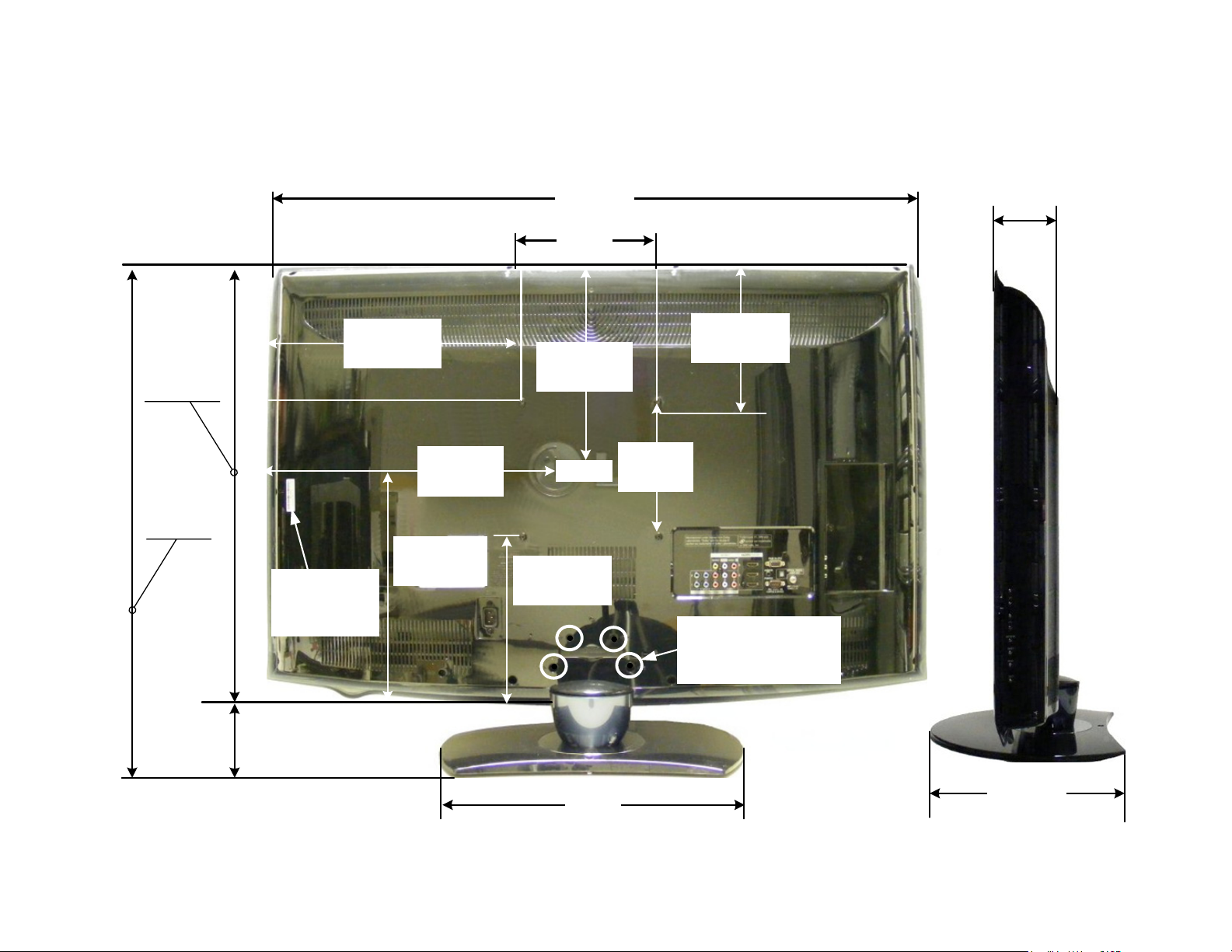
42LH90 Product Dimensions
42LH90 Product Dimensions
There must be at least 4 inches of Clearance on all sides
Wattage
Average 210W
Stand By <1W
42LH90 Dimensions
42"
1066.8mm
7-7/8"
200mm
3-11/16"
93.98mm
28-3/16"
716.28mm
30-5/8"
777.88mm
Model No.
Serial No.
Label
2-7/16"
61.6mm
16-15/16"
430mm
14-1/8"
357.98mm
21"
533.4mm
14-1/8"
357.98mm
Center
10-5/8"
270mm
9-5/8"
244mm
7-7/8"
200mm
Remove 4 screws to
remove stand for
wall mount
Weight without Stand: 43 lb
Weight with Stand: 51.1 lb
17-7/8"
454mm
16
14-3/16"
360.68mm

DISASSEMBLY SECTION
DISASSEMBLY SECTION
This section of the manual will discuss Disassembly, Layout
(Circuit Board Identification) of the 42LH90 LCD Direct View Television.
Upon completion of this section the Technician will have a better
understanding of the disassembly procedures, the layout of the printed
Disassembly:
circuit boards and be able to identify each board.
17
February 2010
LCD DV 42LH90
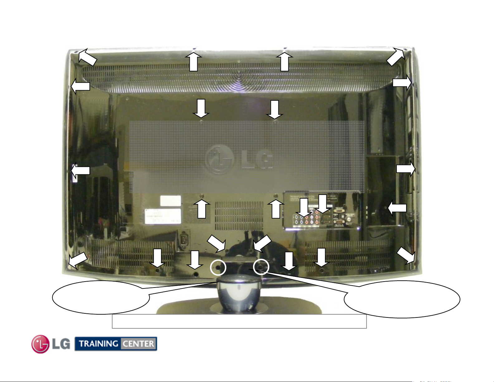
Removing the Back Cover
Removing the Back Cover
Remove the 23 screws indicated.
Pay attention to the size and type of screw
as there are many different types.
Putting in an improper screw when
reassembling may Cause damage.
Decorative Plastic
Cap (if used) must
be removed.
The Stand does not need to be removed before removing the back.
18
February 2010
Bottom two screws do
not have to be
removed.
LCD DV 42LH90
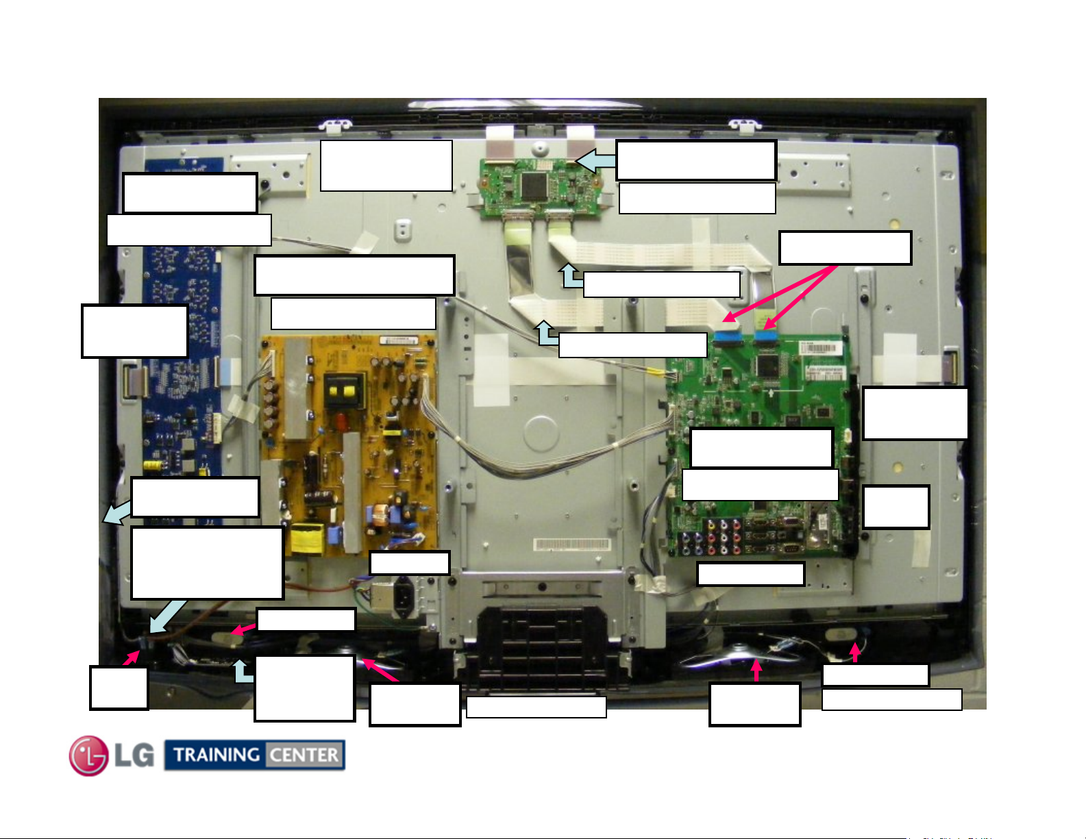
Circuit Board Layout
Circuit Board Layout
INVERTER
p/n EAY60702001
Left LED
Connection
Side Keys
Intelligent
Sensor / IR
TFT Panel
EAJ60694101
POWER SUPPLY
p/n EAY58584001
AC Input
T-CON board
p/n EAT60665101
LVDS Cables
p/n EAD60679428
p/n EAD60679364
Right LED
Connection
Main Board
p/n EBR62151101
Side
Inputs
Rear Inputs
Power
Button
Tweeter R
Moving
LED
Full Range
Speaker R
p/n EAB58534501
19
Full Range
Speaker L
February 2010
Tweeter L
p/n EAB58536001
LCD DV 42LH90
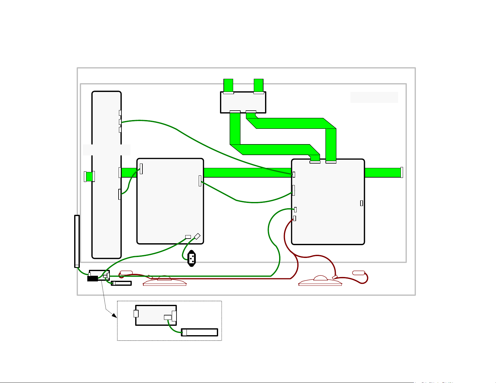
42LH90 Connector Identification Diagram
42LH90 Connector Identification Diagram
CN5 CN4
T-CON
CN305 N/C
CN306
CN307 N/C
CN1
INVERTER
TFT PANEL
CN2
P100
CN4
CN3
CN1
KEY BOARD
IR
Main
Power
LED
P103
P203
IR
P100
POWER
SUPPLY
SK101
P201
SK100
P101
J1
AC In
LED
20
P3500 P3502
P3501
P700
MAIN
BOARD
P1200
P600
Speakers (Front Left)Speakers (Front Right)
P101N/C
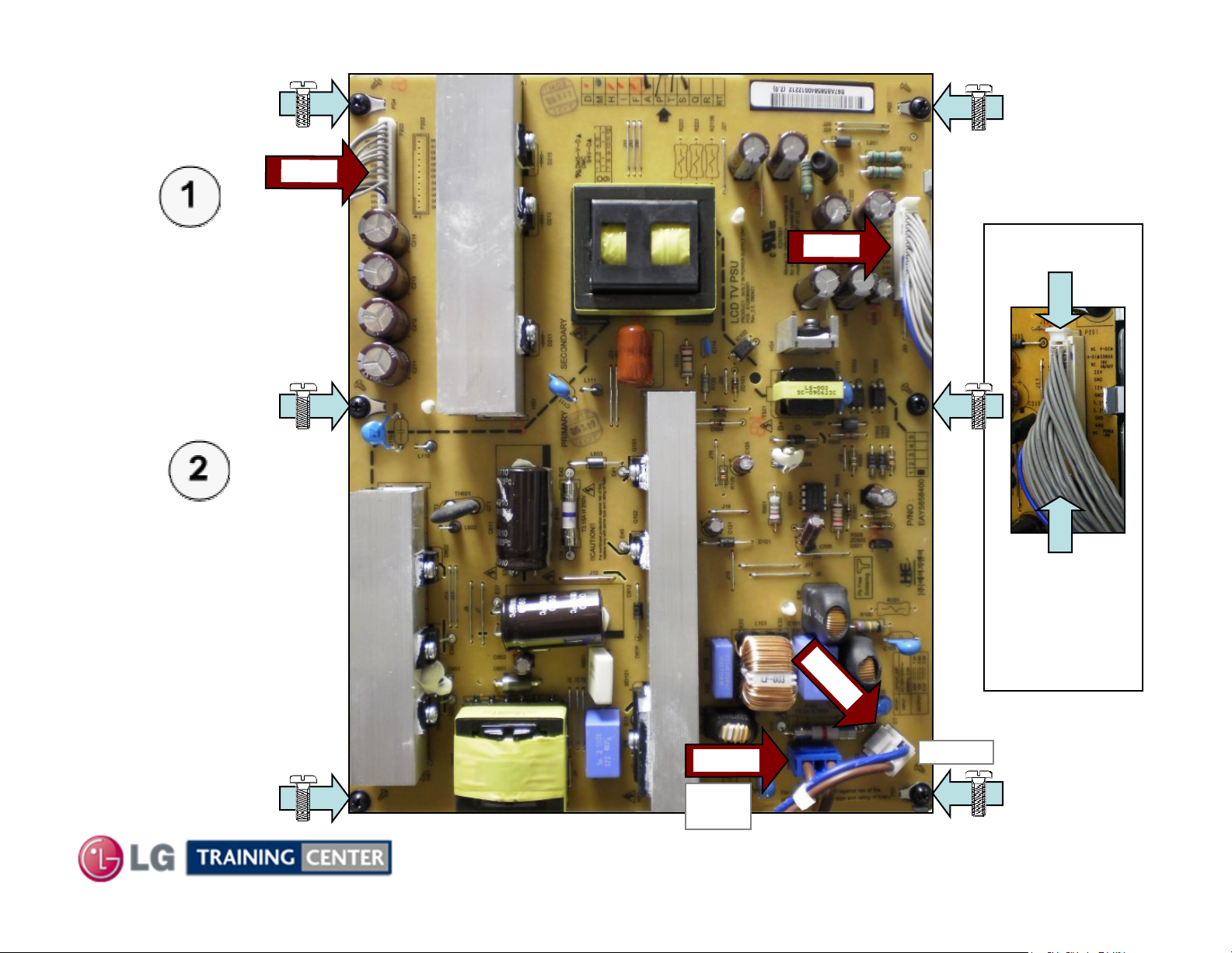
Power Supply
Power Supply
Board Removal
Board Removal
Disconnect
P201, P203,
AC In SK100
and SK101.
Remove the 6
P
2
3
0
P
2
1
0
P201
screws indicated
by the arrows.
21
SK
SK101
Power
Switch
February 2010
Press in
Two tabs
to release
lock
1
0
0
AC In
LCD DV 42LH90
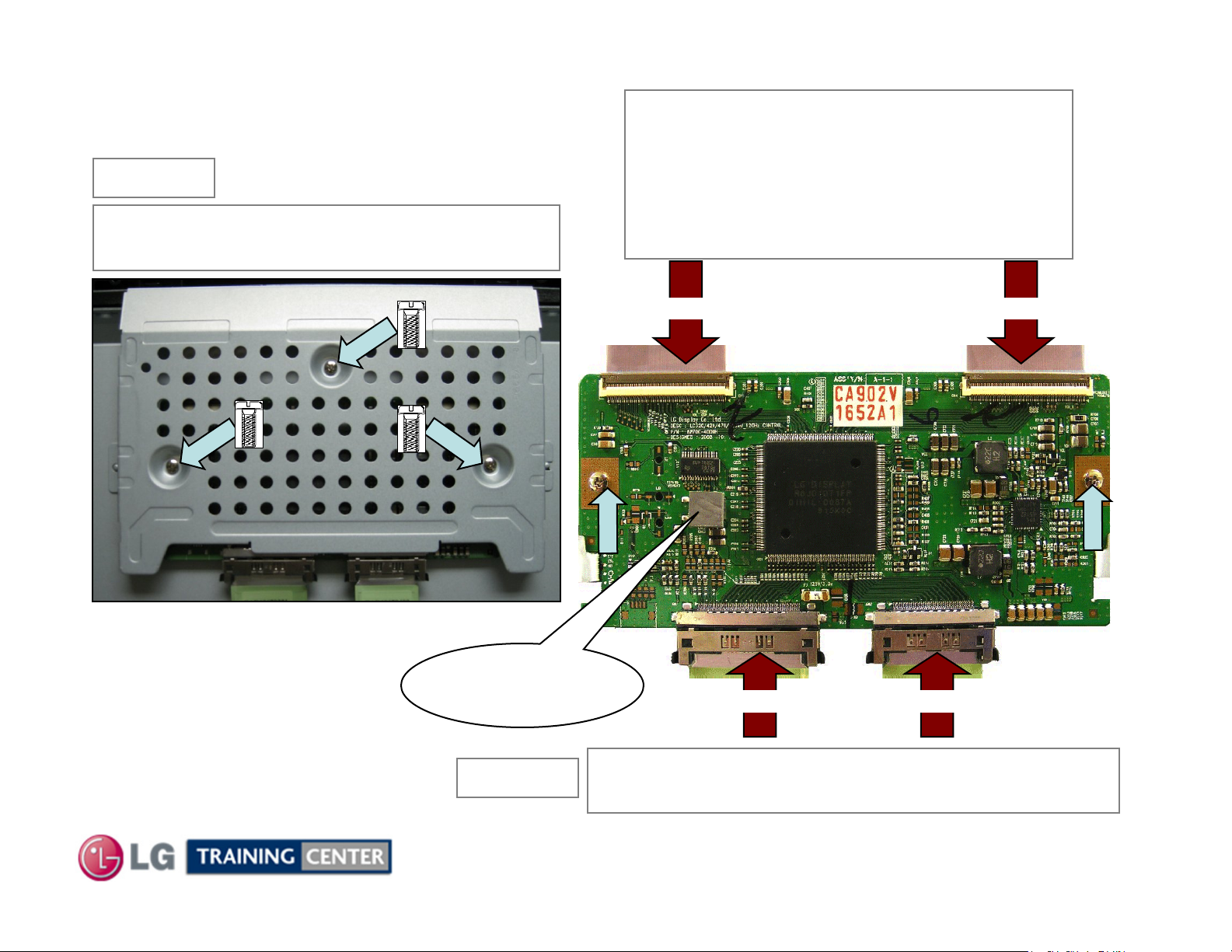
CON Board Removal
TT--CON Board Removal
STEP (1)
Remove the 3 Screws in the T-CON
shield and remove the shield
The two screws shown in the picture
below are for the Service Position.
They would have been removed
when removing the shield.
Be sure to reinstall them if
servicing the T-CON Board.
CN5 CN4
Note: Chocolate
(Heat Sink
Material)
STEP (2)
CN1 CN2
Disconnect CN1, CN2, CN4 and CN5.
See next slide for details about removing cables.
22
February 2010
LCD DV 42LH90
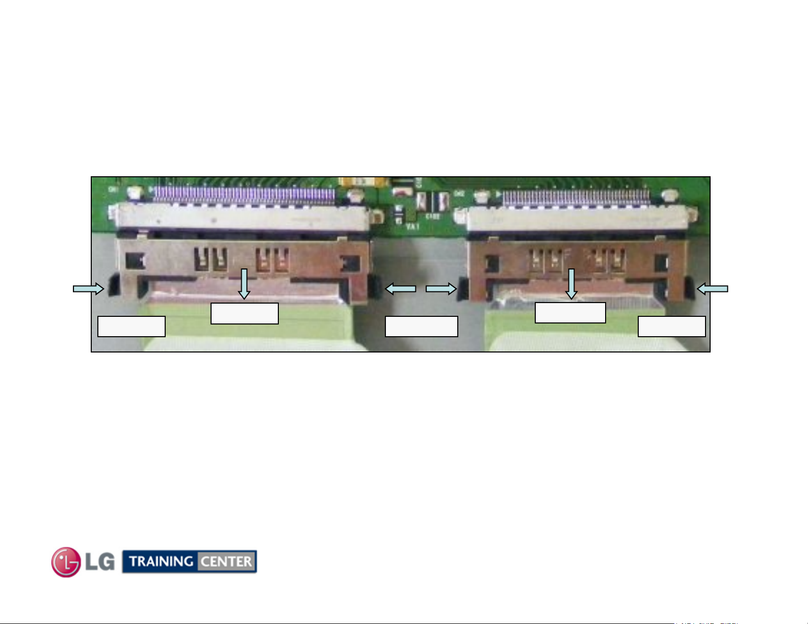
CON Board Removal Board Continued (Unlocking CN1 and CN2 LVDS Ca
TT--CON Board Removal Board Continued (Unlocking CN1 and CN2 LVDS Ca
bles)
bles)
Press In
Press in on the two tabs and slowly rock the cable out of the connector.
(CN1) LVDS
Pull Out
To remove the LVDS cables CN1 and CN2;
(Shown by the arrows in Figure above)
Press In
(CN2) LVDS
Pull Out
Press In
Note: The tabs are fragile, use caution, they may break.
23
February 2010
LCD DV 42LH90
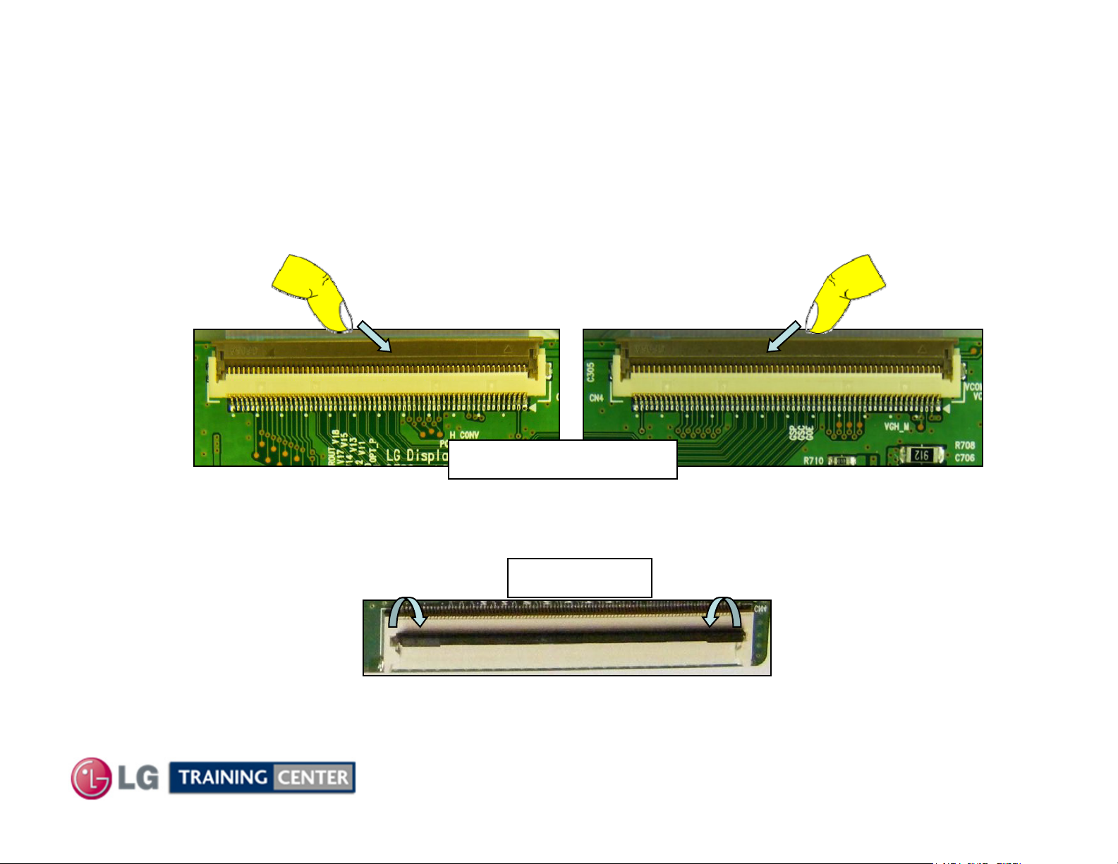
CON Board Removal Board Continued (Unlocking CN4 and CN5 LVDS Ca
TT--CON Board Removal Board Continued (Unlocking CN4 and CN5 LVDS Ca
To remove the flex cables to the TFT Panel, CN4 or CN5, place a soft thin object like a
fingernail underneath the black locking tab and gently pull forward.
(Shown by the arrows in Fig 1 and 2)
bles)
bles)
Fig 1
Fig 2
CN5 or CN4 Locked
Flip the lock up and back from the flex cable.
Then the flex cable can be easily removed.
Unlocked
Fig 3
The locking tab is flipped down
24
February 2010
LCD DV 42LH90
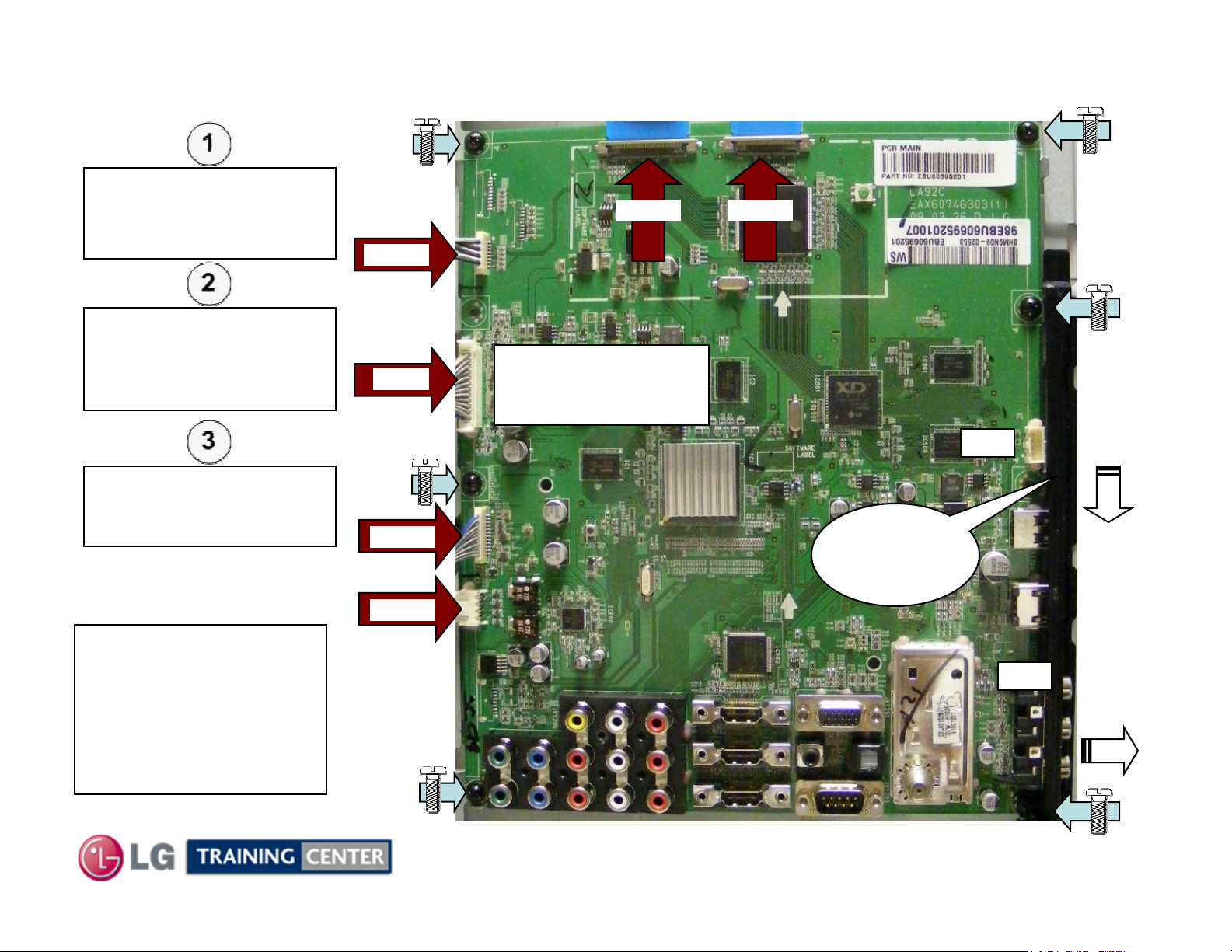
Removing the Main Board
Removing the Main Board
Disconnect P3500,
P3501, P3502, P1200,
P700 and P600
P3501
Remove any tape holding
down any cables.
Remove the 6 screws
indicated by the arrows.
Remove decorative
plastic and remove the
board.
P700
P1200
Flip the locking tab upward, pull the LVDS ribbon out.
P3500 P3502
Press in on the top
and bottom release
tabs to remove.
Decorative
Plastic
(See a and b)
n/c
(b)
Lift
Out
Pull
Down
NOTE: Always check on
top and behind the Large
ICs. And look for a piece
of Chocolate
(Heat Transfer Material).
Be sure to transfer to
new Board if present.
P600
25
February 2010
n/c
(a)
Slide
Right
LCD DV 42LH90
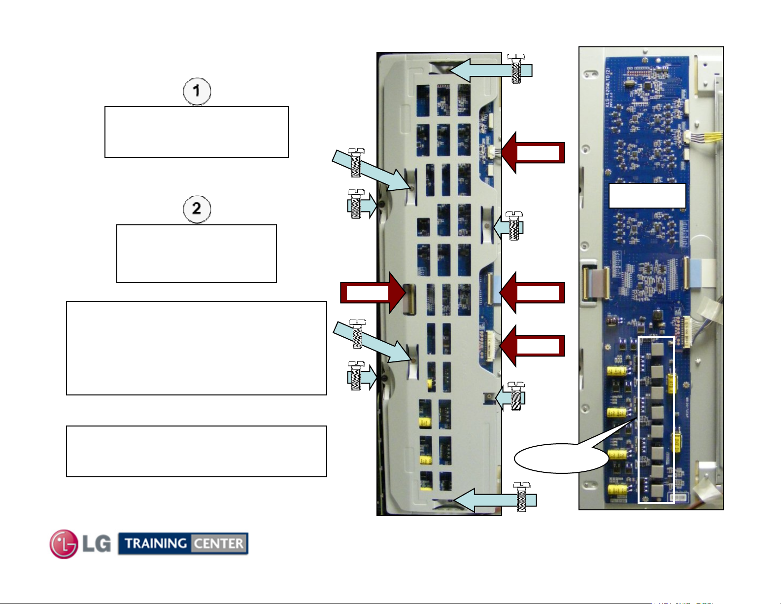
Removing the Inverter Board
Removing the Inverter Board
Remove the 8 screws
indicated by the arrows.
Remove the Inverter Shield.
Use caution, do not allow screws to fall.
Disconnect CN1,
CN3, CN4 and CN306.
Remove the Inverter.
CN306
Inverter
NOTE: Always check for Chocolate
(Heat Transfer Material).
Be sure to transfer to new Board if present
and replace in the correct position.
There should be 8 pieces on the DC to DC
converter coils near the bottom right.
NOTE: If Servicing the Board, return the
screws into the board to provide stability
and grounding.
CN3
26
CN4
CN1
Chocolate
February 2010
LCD DV 42LH90
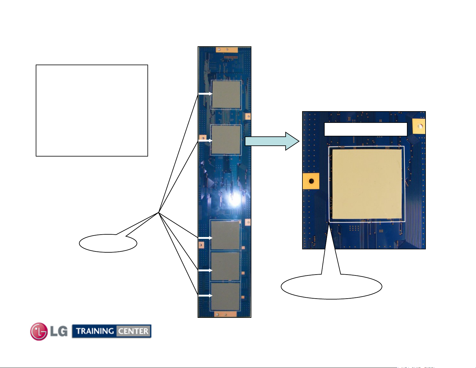
Removing the Inverter Board (Chocolate Notice) Back Side of the
Removing the Inverter Board (Chocolate Notice) Back Side of the
On the back side of the
Inverter are 5 pieces of
Chocolate, (Heat Transfer
and Noise reduction pads).
Be sure to replace these on
the New Inverter if the board
is replaced.
Be sure they do not fall off if
the Inverter is removed.
Chocolate Close Up
Board
Board
Chocolate
27
Chocolate Location
White Box Outline
February 2010
LCD DV 42LH90
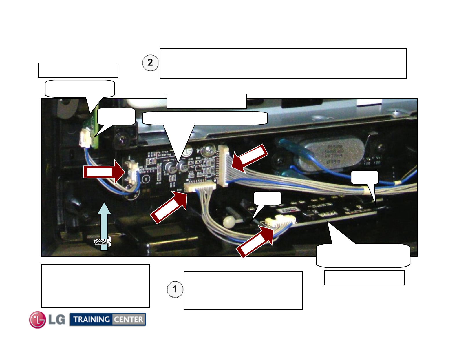
Removing Front Boards (IR Board and Moving LED Board)
Removing Front Boards (IR Board and Moving LED Board)
Disconnect P101 and P102.
Note P102 is behind the Power Switch.
p/n EBR62127501
Remove the IR board by removing the 1 screw and lift out the board.
Key board
p/n EBR62128101
P100
P102
The Power Switch has
been removed for easier
viewing of connectors and
screws.
IR board / Intelligent Sensor
101
P
100
P
J
Disconnect J1 or P100. Remove
the LED board by lifting up on
the two locking tabs and pull
backwards on the board.
Tab
Tab
1
Moving LED board
(Power LEDs)
p/n EBR61674001
28
February 2010
LCD DV 42LH90
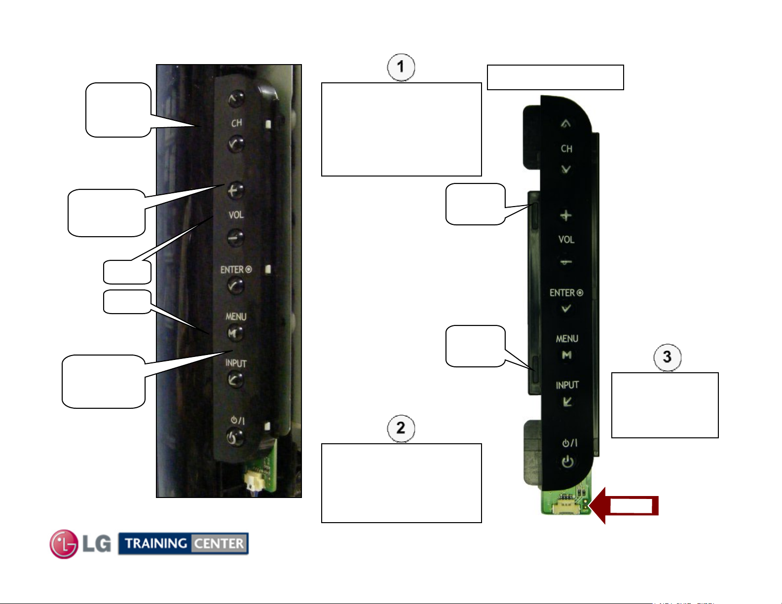
Removing Front Key Board
Removing Front Key Board
Key
Board
p/n EBR62127501
To Remove the Key
Board, Apply Pressure at
point (A) on the Key
Board itself while using
an object to slightly pry
out from the top.
(A)
Push In
Tab
Tab
(B)
Push In
Tab
Slots
Tab
Slots
Apply Pressure at point
(B) on the Key Board
itself while using an
object to slightly pry out
from the bottom.
Disconnect
P100
and remove the
Key Board
P1
0
0
29
February 2010
LCD DV 42LH90

TROUBLESHOOTING SECTION
TROUBLESHOOTING SECTION
Troubleshooting:
This section of the manual will also discuss
troubleshooting.
Upon completion of this section the Technician will have
a better understanding of how to diagnosis and resolve
problems.
30
February 2010
LCD DV 42LH90
 Loading...