

Lg 42LG30R User Manual [es]
User’s Guide Specification
User’s Guide Specification
Model Description
1.
담 당 관리자
KIM Won Mi
08.02.11
KANG
KWANG SUK
08.02.11
MODEL
SUFFIX
2.
42PG20R-MA
PANAMA
Printing Specification
BRAND
Product Name
LG
42PG20R
Part No.
MFL41469207
(0808-REV08)
1. Trim Size (Format) : 185mm x 260 mm
2. Printing Colors
• Cover : 1 COLOR (BLACK)
• Inside : 1 COLOR (BLACK)
3. Stock (Paper)
• Cover : Coated paper , S/White 150 g/㎡
• Inside : Uncoated paper , 백상지 60 g/㎡
4. Printing Method : Off set
5. Bindery : Perfect bind
6. Language : English/Spanish (2)
7. Number of pages : 200
“This part contain Eco-hazardous substances (Pb, Cd, Hg, Cr6+, PBB, PBDE, etc.) within LG standard level,
N
O
T
E
S
Details should be followed Eco-SCM management standard[LG(56)-A-2524].
Especially, Part should be followed and controlled the following specification.
(1)Eco-hazardous substances test report should be submitted
when Part certification test and First Mass Production.
(2) Especially, Don’t use or contain lead(Pb) and cadmium(Cd) in ink.
Special Instructions3.
(1) Origin Notification
* LGEMX : Printed in Mexico
* LGERS : Printed in Mexico
* LGEAZ : Printed in Brazil
* LGESP : Printed in Brazil
* LGESY : Printed in China
4.
Changes
8/22/08 KIM WON MI S8-27109 [ H5 ] Revised the sp OSD in the manual by requesting the S/W.
8
5/28/08 KIM WON MI S8-21405 [ H5, taiwan ] Added the LCD stand installeration and
7
6
5
4
3
2
1
REV.
NO.
5/9/08 KIM WON MI S8-19678 [ H5 ] Change the manual contents.
5/9/08 KIM WON MI S8-19510 [ H5 ] Change the manual revision.
3/28/08 KIM WON MI S8-15138 [ H5 ] Change the manual revision.
3/12/08 KIM WON MI S8-13277 [H5 ]Change the manual revision.
3/6/08 KIM WON MI S8-12537 [H5 ] Changed the function by S/W request
2/27/08 KIM WON MI S8-11445 [ H5 ] Change the manual and QSG revision.
MM/DD/YY
SIGNATURE
* LGENT : Printed in China
* LGENP : Printed in China
* LGEIL : Printed in India
* LGEDI : Printed in Indonesia
* LGEIN : Printed in Indonesia
CHANGE NO.
* LGEMA : Printed in Poland
* LGEWA : Printed in U.K.
* LGEEG : Printed in Egypt
* LGERA : Printed in Russia
* LGEAK : Printed in Kazakhstan
Changed the spanish OSD.
CHANGE CONTENTS
* LGETH : Printed in Thailand
* LGEVN : Printed in Vietnam
Front cover
LG(EN)
Pagination sheet
Pagination sheet
P/NO.MFL41469207
Total pages : 200
P/NO.
LG(SP)
1….
1….….
….
…. ….
…. ….
98
Rear cover
98

Please read this manual carefully before operating
your set.
Retain it for future reference.
Record model number and serial number of the set.
See the label attached on the back cover and quote
this information to your dealer
when you require service.
LCD TV PLASMA TV
OWNER’S MANUAL
LCD TV MODELS
26LG30R
32LG30R
37 LG 30 R
42LG30R
47LG30R
32LG50FR
42LG50FR
PLASMA TV MODELS
42PG20R
50PG20R
32PC5RA
P/NO : MFL41469207 (0808-REV08)
www.lge.com
MFL41469207en-Edit1 8/22/08 8:54 AM Page 1
MFL41469207en-Edit1 8/22/08 8:54 AM Page 2

1
WARNING / CAUTION
The lightning flash with arrowhead symbol, within an equilateral triangle,
is intended to alert the user to the presence of uninsulated “dangerous voltage” within the product’s enclosure that may be of sufficient magnitude to
constitute a risk of electric shock to persons.
The exclamation point within an equilateral triangle is intended to alert the
user to the presence of important operating and maintenance (servicing)
instructions in the literature accompanying the appliance.
TO REDUCE THE RISK OF ELECTRIC SHOCK DO NOT REMOVE COVER (OR
BACK). NO USER SERVICEABLE PARTS INSIDE. REFER TO QUALIFIED SERVICE
PERSONNEL.
WARNING/CAUTION
TO REDUCE THE RISK OF FIRE AND ELECTRIC SHOCK, DO NOT EXPOSE THIS
PRODUCT TO RAIN OR MOISTURE.
MFL41469207en-Edit1 8/22/08 8:54 AM Page 1

2
SAFETY INSTRUCTIONS
IMPORTANT SAFETY INSTRUCTIONS
Important safety instructions shall be provided with each apparatus. This information shall be given in a separate
booklet or sheet, or be located before any operating instructions in an instruction for installation for use and
supplied with the apparatus.
This information shall be given in a language acceptable to the country where the apparatus is intended to be used.
The important safety instructions shall be entitled “Important Safety Instructions”. The following safety
instructions shall be included where applicable, and, when used, shall be verbatim as follows. Additional safety
information may be included by adding statements after the end of the following safety instruction list. At the
manufacturer’s option, a picture or drawing that illustrates the intent of a specific safety instruction may be
placed immediately adjacent to that safety instruction:
Read these instructions.
Keep these instructions.
Heed all warnings.
Follow all instructions.
Do not use this apparatus near water.
Clean only with dry cloth.
Do not block any ventilation openings. Install in
accordance with the manufacturer’s instructions.
Do not install near any heat sources such as
radiators, heat registers, stoves, or other apparatus
(including amplifiers)that produce heat.
When mounting a TV it on the wall, make sure
not to install TV by the hanging power and signal cables on the back of the TV.
Do not defeat the safety purpose of the polarized
or grounding-type plug. A polarized plug has
two blades with one wider than the other. A
grounding type plug has two blades and a third
grounding prong, The wide blade or the third
prong are provided for your safety. If the provided
plug does not fit into your outlet, consult an
electrician for replacement of the obsolete outlet.
Protect the power cord from being walked on
or pinched particularly at plugs, convenience
receptacles, and the point where they exit from
the apparatus.
Only use attachments/accessories specified by
the manufacturer.
Unplug this apparatus during lightning storms
or when unused for long periods of time.
1
2
3
4
6
7
8
9
5
MFL41469207en-Edit1 8/22/08 8:54 AM Page 2

3
Use only with the cart, stand, tripod, bracket,
or table specified by the manufacturer, or sold
with the apparatus. When a cart is used, use
caution when moving the cart/apparatus
combination to avoid injury from tip-over.
Never touch this apparatus or antenna during
a thunder or lighting storm.
Do not allow a impact shock or any objects to
fall into the product, and do not drop onto the
screen with something.
Refer all servicing to qualified service personnel.
Servicing is required when the apparatus has
been damaged in any way, such as power-supply
cord or plug is damaged, liquid has been spilled
or objects have fallen into the apparatus, the
apparatus has exposed to rain or moisture,
does not operate normally, or has been
dropped.
CAUTION concerning the Power Cord :
Most appliances recommend they be placed
upon a dedicated circuit; that is, a single outlet
circuit which powers only that appliance and
has no additional outlets or branch circuits.
Check the specification page of this owner's
manual to be certain.
Do not overload wall outlets. Overloaded wall
outlets, loose or damaged wall outlets, extension
cords, frayed power cords, or damaged or
cracked wire insulation are dangerous. Any of
these conditions could result in electric shock
or fire. Periodically examine the cord of your
appliance, and if its appearance indicates damage or deterioration, unplug it, discontinue use
of the appliance, and have the cord replaced
with an exact replacement part by an authorized
servicer. Protect the power cord from physical
or mechanical abuse, such as being twisted,
kinked, pinched, closed in a door, or walked
upon. Pay particular attention to plugs, wall
outlets, and the point where the cord exits the
appliance.
Outdoor use marking :
WARNING - To reduce the risk of fire or elec-
tric shock, do not expose this appliance to rain
or moisture.
Wet Location Marking : Apparatus shall not be
exposed to dripping or splashing and no
objects filled with liquids, such as vases, shall
be placed on or over apparatus.
GGRROOUUNNDD IINNGG
Ensure that you connect the earth ground wire
to prevent possible electric shock. If grounding
methods are not possible, have a qualified
electrician install a separate circuit breaker.
Do not try to ground the unit by connecting it
to telephone wires, lightening rods, or gas pipes.
DDIISSCCOONNNNEECCTTIINNGG DD EEVVIICCEE FFRROOMM MMAAIINNSS
Mains plug is the disconnecting device. The
plug must remain readily operable.
Keep the product away from direct sunlight.
- The product can be damaged.
Do not press strongly upon the panel with a hand or
sharp object such as nail, pencil or pen, or make a
scratch on it.
10
13
11
12
14
15
16
17
18
Power
Supply
Short-circuit
Breaker
19
20
MFL41469207en-Edit1 8/22/08 8:54 AM Page 3
4
CONTENTS
WARNING/CAUTION
. . . . . . . . . . . . . . . . . . . . . . . . . . . . . . . 1
SAFETY INSTRUCTIONS
. . . . . . . . . . . . . . . . . . . . . . . . . . 2
PREPARATION
Accessories
. . . . . . . . . . . . . . . . . . . . . . . . . . . . . . . . . . . . . . . . . . . . . . . . . . . . . . 7
Front Panel Information
. . . . . . . . . . . . . . . . . . . . . . . . . . . . . . . . . . . . . 8
Back Panel Information . . . . . . . . . . . . . . . . . . . . . . . . . . . . . . . . . . . . 10
Stand Installation
. . . . . . . . . . . . . . . . . . . . . . . . . . . . . . . . . . . . . . . . . . . . 13
Cable Management
. . . . . . . . . . . . . . . . . . . . . . . . . . . . . . . . . . . . . . . . . 15
Securing the TV to the wall fall over.
. . . . . . . . . . . . . . . . . 17
Protection Cover
. . . . . . . . . . . . . . . . . . . . . . . . . . . . . . . . . . . . . . . . . . . . . 18
Swivel Stand
. . . . . . . . . . . . . . . . . . . . . . . . . . . . . . . . . . . . . . . . . . . . . . . . . . . . 18
Desktop Pedestal Installation
. . . . . . . . . . . . . . . . . . . . . . . . . . . 19
Wall Mount: Horizontal Installation
. . . . . . . . . . . . . . . . . . . 19
Attaching The TV To a Desk
. . . . . . . . . . . . . . . . . . . . . . . . . . . . . 19
Antenna Connection
. . . . . . . . . . . . . . . . . . . . . . . . . . . . . . . . . . . . . . . 20
EXTERNAL EQUIPMENT SETUP
HD Receiver Setup
. . . . . . . . . . . . . . . . . . . . . . . . . . . . . . . . . . . . . . . . . 21
DVD Setup
. . . . . . . . . . . . . . . . . . . . . . . . . . . . . . . . . . . . . . . . . . . . . . . . . . . . . 24
VCR Setup
. . . . . . . . . . . . . . . . . . . . . . . . . . . . . . . . . . . . . . . . . . . . . . . . . . . . . 27
Other A/V Source Setup
. . . . . . . . . . . . . . . . . . . . . . . . . . . . . . . . . 30
PC Setup
. . . . . . . . . . . . . . . . . . . . . . . . . . . . . . . . . . . . . . . . . . . . . . . . . . . . . . . . 31
External Stereo Setup . . . . . . . . . . . . . . . . . . . . . . . . . . . . . . . . . . . . . . 37
AV Out Setup
. . . . . . . . . . . . . . . . . . . . . . . . . . . . . . . . . . . . . . . . . . . . . . . . . 37
WATCHING TV / CHANNEL CONTROL
Remote Control Key Functions . . . . . . . . . . . . . . . . . . . . . . . . . 38
Turning On TV . . . . . . . . . . . . . . . . . . . . . . . . . . . . . . . . . . . . . . . . . . . . . . . . 42
Channel Selection
. . . . . . . . . . . . . . . . . . . . . . . . . . . . . . . . . . . . . . . . . . . 42
Volume Adjustment . . . . . . . . . . . . . . . . . . . . . . . . . . . . . . . . . . . . . . . . . 42
Quick Menu
. . . . . . . . . . . . . . . . . . . . . . . . . . . . . . . . . . . . . . . . . . . . . . . . . . . . 43
On-Screen Menus Selection
. . . . . . . . . . . . . . . . . . . . . . . . . . . . 44
Channel Search
. . . . . . . . . . . . . . . . . . . . . . . . . . . . . . . . . . . . . . . . . . . . . . . 45
- Auto Turning
. . . . . . . . . . . . . . . . . . . . . . . . . . . . . . . . . . . . . . . . . . . . 45
- Manual Turning:Adding / Deleting Channels
. . . 46
Fine Tuning Adjustment
. . . . . . . . . . . . . . . . . . . . . . . . . . . . . . . . . . . 47
Booster . . . . . . . . . . . . . . . . . . . . . . . . . . . . . . . . . . . . . . . . . . . . . . . . . . . . . . . . . . 48
Favorite Channels Setup . . . . . . . . . . . . . . . . . . . . . . . . . . . . . . . . . . 49
Key Lock
. . . . . . . . . . . . . . . . . . . . . . . . . . . . . . . . . . . . . . . . . . . . . . . . . . . . . . . . . 50
AV Mode . . . . . . . . . . . . . . . . . . . . . . . . . . . . . . . . . . . . . . . . . . . . . . . . . . . . . . . . 51
SimpLink
. . . . . . . . . . . . . . . . . . . . . . . . . . . . . . . . . . . . . . . . . . . . . . . . . . . . . . . . . 52
PICTURE CONTROL
Watching PIP(Picture-In-Picture) . . . . . . . . . . . . . . . . . . . . . . 54
Picture Size (Aspect Ratio) Control
. . . . . . . . . . . . . . . . . . 55
Preset Picture Settings
. . . . . . . . . . . . . . . . . . . . . . . . . . . . . . . . . . . . . 56
- Picture Mode- Preset
. . . . . . . . . . . . . . . . . . . . . . . . . . . . . . . . 56
- Auto Color Tone Control(Cool/Medium/Warm)
. . 57
Manual Picture Adjustment
. . . . . . . . . . . . . . . . . . . . . . . . . . . . . . 58
- Picture Mode- User Mode
. . . . . . . . . . . . . . . . . . . . . . . . . 58
- Color Tone - User Mode
. . . . . . . . . . . . . . . . . . . . . . . . . . . 59
XD - Picture Improvement Technology
. . . . . . . . . . . . . 60
Advanced - Gamma
. . . . . . . . . . . . . . . . . . . . . . . . . . . . . . . . . . . . . . . . . 62
Advanced - Film Mode
. . . . . . . . . . . . . . . . . . . . . . . . . . . . . . . . . . . . . 63
Advanced - Black (Darkness) Level
. . . . . . . . . . . . . . . . . . . 64
Advanced - Eye Care
. . . . . . . . . . . . . . . . . . . . . . . . . . . . . . . . . . . . . . . 65
Picture Reset
. . . . . . . . . . . . . . . . . . . . . . . . . . . . . . . . . . . . . . . . . . . . . . . . . 66
Power Indicator
. . . . . . . . . . . . . . . . . . . . . . . . . . . . . . . . . . . . . . . . . . . . . . 67
Image Sticking Minimization (ISM) Method
. . . . . . 68
Power Saving Picture Mode
. . . . . . . . . . . . . . . . . . . . . . . . . . . . . . 69
Factory Reset
. . . . . . . . . . . . . . . . . . . . . . . . . . . . . . . . . . . . . . . . . . . . . . . . . . 70
MFL41469207en-Edit1 8/22/08 8:54 AM Page 4
5
SOUND & LANGUAGE CONTROL
Auto Volume Leveler . . . . . . . . . . . . . . . . . . . . . . . . . . . . . . . . . . . . . . . . 71
Preset Sound Setting - Sound Mode
. . . . . . . . . . . . . . . . 72
Sound Setting Adjustment - User Mode
. . . . . . . . . . . 73
Balance
. . . . . . . . . . . . . . . . . . . . . . . . . . . . . . . . . . . . . . . . . . . . . . . . . . . . . . . . . . . 74
TV Speakers On/Off Setup
. . . . . . . . . . . . . . . . . . . . . . . . . . . . . . 75
Selecting Audio Out
. . . . . . . . . . . . . . . . . . . . . . . . . . . . . . . . . . . . . . . . 76
On-Screen Menus Language Selection
. . . . . . . . . . . . . . 76
Closed Caption
. . . . . . . . . . . . . . . . . . . . . . . . . . . . . . . . . . . . . . . . . . . . . . . 77
TIME SETTING
Clock Setup
. . . . . . . . . . . . . . . . . . . . . . . . . . . . . . . . . . . . . . . . . . . . . . . . . . . 78
Auto On/Off Time Setting
. . . . . . . . . . . . . . . . . . . . . . . . . . . . . . 79
Sleep Timer Setting
. . . . . . . . . . . . . . . . . . . . . . . . . . . . . . . . . . . . . . . . . 80
Auto Shut-off Setting
. . . . . . . . . . . . . . . . . . . . . . . . . . . . . . . . . . . . . . . 81
APPENDIX
Troubleshooting
. . . . . . . . . . . . . . . . . . . . . . . . . . . . . . . . . . . . . . . . . . . . . . 82
Maintenance
. . . . . . . . . . . . . . . . . . . . . . . . . . . . . . . . . . . . . . . . . . . . . . . . . . . 83
Product Specifications
. . . . . . . . . . . . . . . . . . . . . . . . . . . . . . . . . . . . .
84
Programming the Remote Control
. . . . . . . . . . . . . . . . . . . 86
IR Codes . . . . . . . . . . . . . . . . . . . . . . . . . . . . . . . . . . . . . . . . . . . . . . . . . . . . . . .88
External Control Through RS-232C
. . . . . . . . . . . . . . . . . .90
MFL41469207en-Edit1 8/22/08 8:54 AM Page 5
6
PREPARATION
FOR LCD TV
If the TV feels cold to the touch, there may be a small “flicker” when it is turned on. This is normal, there is nothing wrong with TV.
Some minute dot defects may be visible on the screen, appearing as tiny red, green, or blue spots. However, they
have no adverse effect on the monitor's performance.
Avoid touching the LCD screen or holding your finger(s) against it for long periods of time. Doing so may produce
some temporary distortion effects on the screen.
OOnn DDiissppoossaall ((OOnnllyy,, HHgg..ll aammpp uuss eedd LLCCDD TT VV))
a. The fluorescent lamp used in this product contains a small amount of mercury.
b. Do not dispose of this product with general household waste.
c. Disposal of this product must be carried out in accordance to the regulations of your local authority.
PREPARATION
Ferrite core can be used to reduce the electromagnetic
wave when connecting the power cord.
The closer the location of the ferrite core to the power
plug, the better it is.
Use of ferrite core
(
This feature is not available for all models.
)
Install the power plug closely.
MFL41469207en-Edit1 8/22/08 8:54 AM Page 6
PREPARATION
7
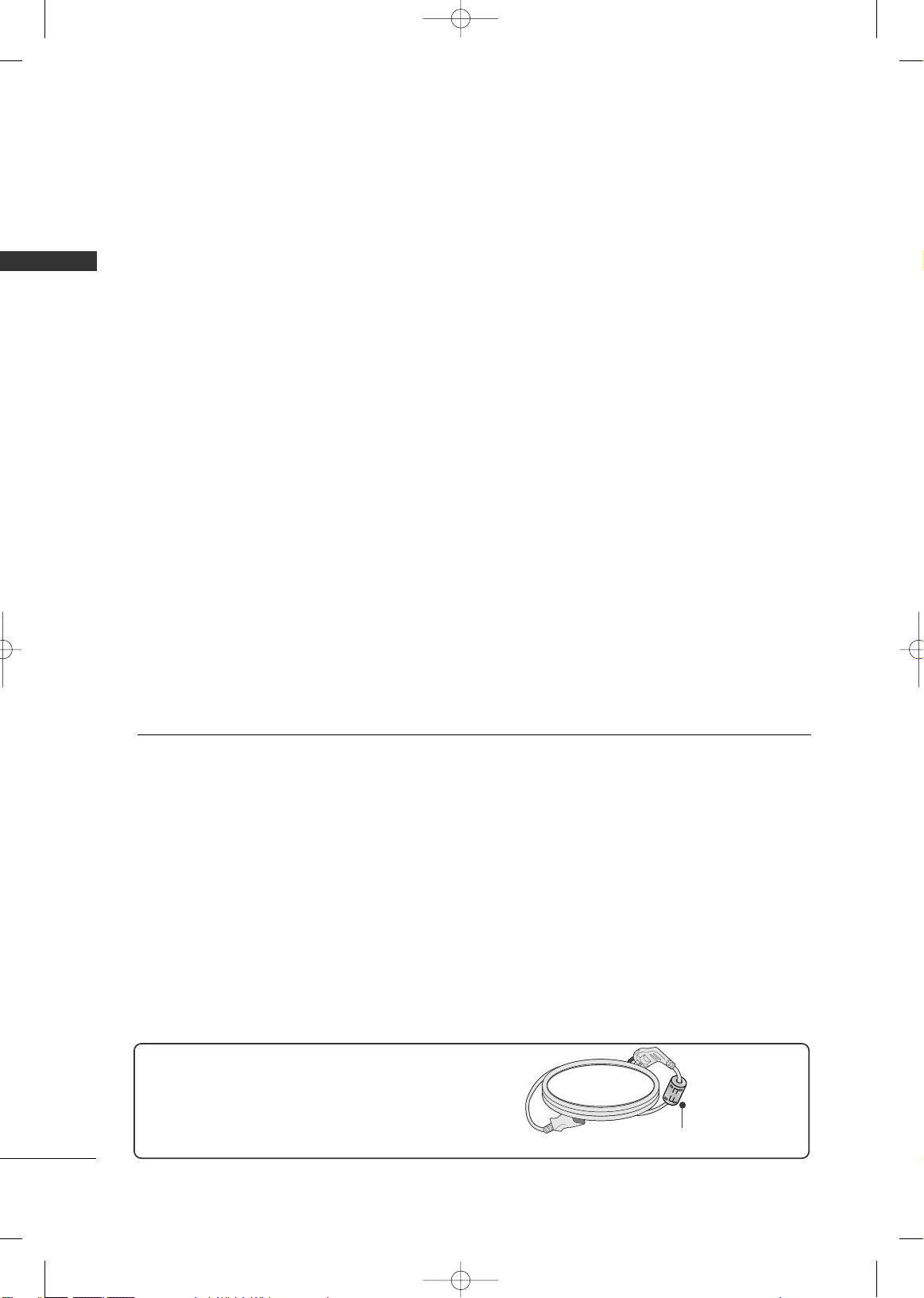
ACCESSORIES
Ensure that the following accessories are included with your TV. If an accessory is missing, please contact the
dealer where you purchased the TV.
The accessories included may differ from the images below.
Owner's Manual
1.5V 1.5V
Owner’s Manual
Batteries
(Some Models)
Power Cord
RF Adapter (Some Models)
You must connect it to the antenna
wire after fixing in Antenna Input.
This adapter is only supplied in
Argentina.
* Only wipe spots on the exterior with the polishing cloth.
* Do not wipe roughly when removing stain. Please be cau-
tions of that excessive pressure may cause scratch or discoloration.
Polishing Cloth
(This feature is not available
for all models.)
R
A
T
I
O
P
O
W
E
R
I
N
P
U
T
P
I
C
T
U
R
E
S
O
U
N
D
M
U
T
E
RETURN
A
V
M
O
D
E
F
A
V
Q
. M
E
N
U
M
E
N
U
ENTER
V
O
L
C
H
123
456
78
0
9
Q.VIEW
P
I
P
*
Remote Control
FFoorr PPllaassmmaa TTVV mmooddeellss
Bolts for stand
assembly
(Refer to P.13)
Protection cover
(Refer to p.18)
(This accessories can be different from the figures shown here
depending on your models.)
(Only 42PG20*)
FFoorr LLCCDD TTVV mmooddeellss
Protection cover
(Refer to p.18)
(This accessories can be differ-
ent from the figures shown here
depending on your models.)
Cable Holder
x 4
Screw for stand fixing
(Refer to P.19)
Cable Management Clip
x 1
x 2
(42PG20*)
(50PG20*)
(Only 26/32/42LG30*,
32/42LG50**)
or
Bolts for
stand assembly
(Refer to P.14)
x 4
x 4
(Except 47LG30*)
Only 32PC5**
bolts for stand
assembly
(Refer to p.13)
Holder
(Refer to p.18)
Cover
(Refer to p.18)
(This feature is not available for all
models.)
Ferrite Core
123
456
78
0
9
V
O
L
C
H
E
N
T
E
R
P
O
W
E
R
M
U
T
E
F
A
V
R
A
T
IO
Q
.V
I
E
W
P
I
C
T
U
R
E
S
O
U
N
D
P
I
P
I
N
P
U
T
*
M
E
N
U
Q
.M
E
N
U
R
E
T
U
R
N
A
V
M
O
D
E
*
or
x 4
MFL41469207en-Edit1 8/22/08 8:54 AM Page 7

PREPARATION
8
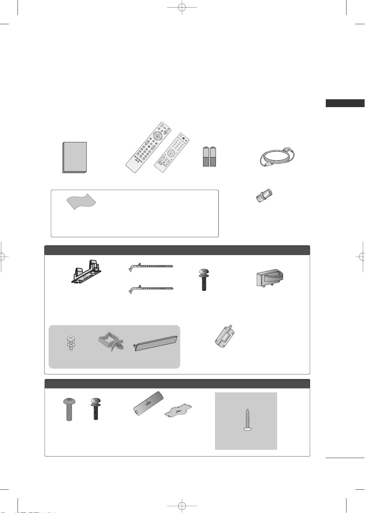
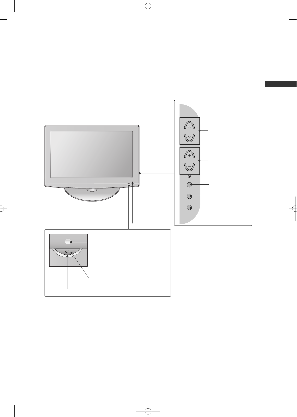
FRONT PANEL INFORMATION
PREPARATION
■
Image shown may differ from your TV.
■
NOTE: If your TV has a protection tape attached, remove the tape.
And then wipe the TV with a cloth (If a polishing cloth is included with your TV, use it).
Plasma TV Models (Only 42/50PG20*)
CHANNEL
Buttons
VOLUME
Buttons
MENU
Button
ENTER
Button
INPUT
Button
CH
VOL
MENU
INPUT
ENTER
Remote Control Sensor
POWER Button
Power/Standby Indicator
Illuminates red in standby mode.
Illuminates green when the set is
switched on.
Plasma TV Models ( Only
32PC5**)
Power/Standby Indicator
• illuminates red in standby mode.
• illuminates green when the TV is switched on.
Remote Control
Sensor
INPUT
Button
MENU
Button
ENTER
Button
VOLUME
Buttons
CHANNEL
Buttons
POWER
Button
CHCH
VOLVOL
ENTERENTER
MENUMENU
INPUTINPUT
MFL41469207en-Edit1 8/22/08 8:54 AM Page 8
PREPARATION
9
LCD TV Models
POWER Button
Power/Standby Indicator
Illuminates red in standby mode.
Illuminates blue when the set is switched on.
(Can be adjusted
PPoowweerr IInnddiiccaattoorr
in the
Option menu.)
CHANNEL
Buttons
VOLUME
Buttons
ENTER Button
MENU Button
INPUT Button
Remote Control Sensor
Intelligent Sensor
Adjusts picture according
to the surrounding conditions (
Only 32/
42L G50**)
MFL41469207en-Edit1 8/22/08 8:54 AM Page 9
CH
VOL
ENTER
MENU
INPUT
PREPARATION
10
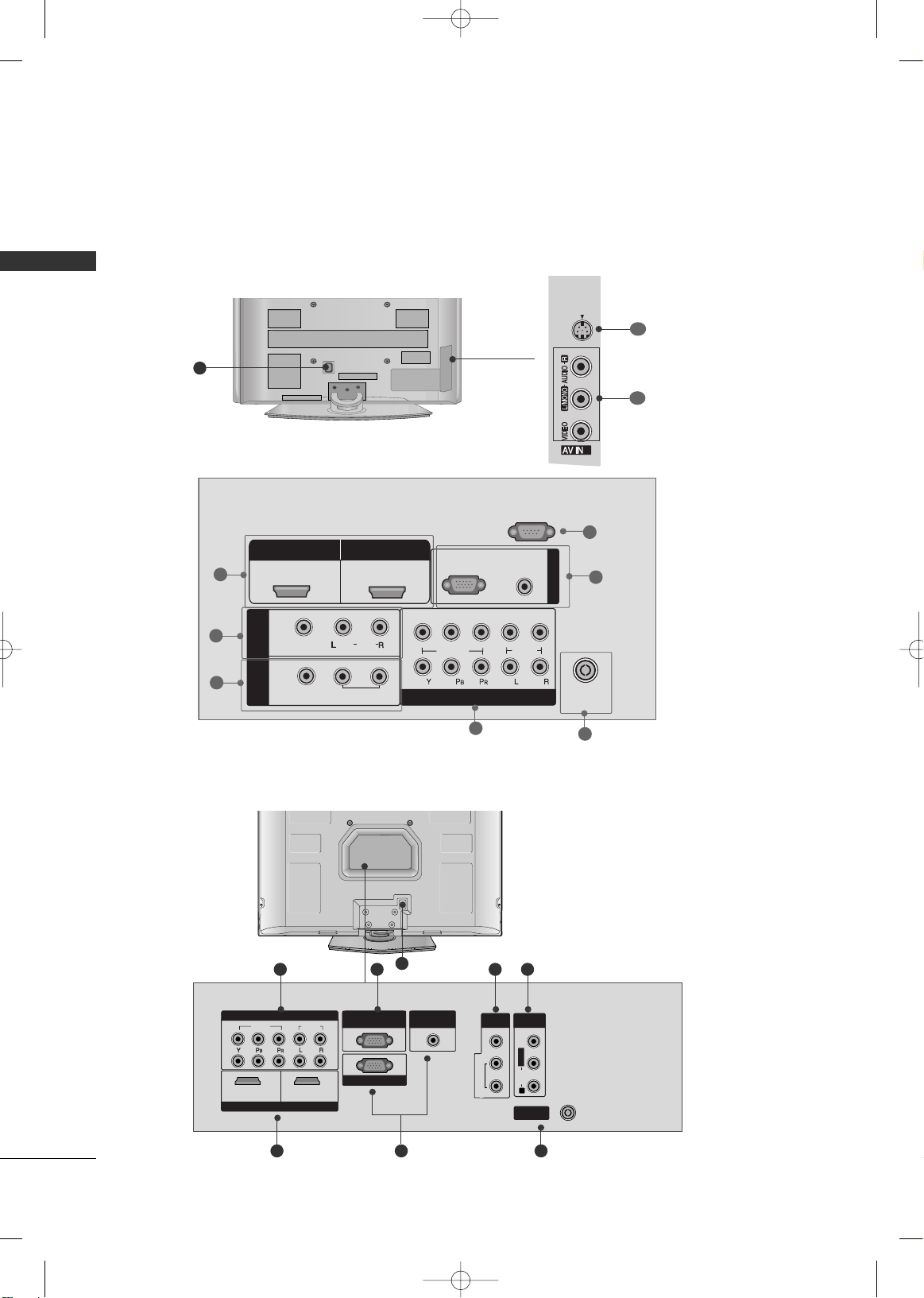
BACK PANEL INFORMATION
PREPARATION
Plasma TV Models ( Only 42/50PG20*)
R
■
Here shown may be somewhat different from your TV.
2
S-VIDEO
2
8
2
1
6
4
3
5
7
10
9
8
VIDEOVIDEO
AUDIOAUDIO
COMPONENTCOMPONENT IN IN
HDMI INHDMI INHDMI/DVI INHDMI/DVI IN
1 2
RGB IN (PC)RGB IN (PC)
ANTENNAANTENNA
IN
1
2
RS-232C INRS-232C IN
(CONTROL(CONTROL & SER & SERVICE)VICE)
AUDIO INAUDIO IN
(RGB/DVI)(RGB/DVI)
AV OUTV OUT
AV INV IN
L/L/MONOMONO
R
AUDIOAUDIO
VIDEOVIDEO
VARIABLE AUDIO OUT
4 7
3 2
1
5
6
Plasma TV Models ( Only
32PC5**)
MFL41469207en-Edit1 8/22/08 8:54 AM Page 10
HDMI/DVI IN
1
IN 1
VIDEO
AV
OUT
HDMI IN
2
(
)
AUDIO
MONO
VARIABLE AUDIO OUT
2
1
RGB(PC)
VIDEO
COMPONENT IN
RS-232C IN
(CONTROL )
AUDIO
(RGB/DVI)
AUDIO
RGB IN
ANTENNA
IN
PREPARATION
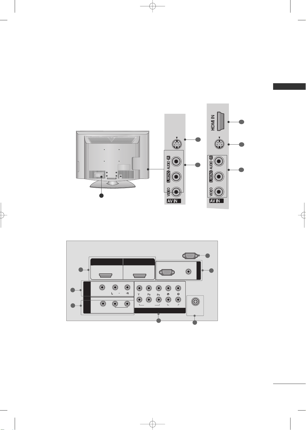
11
LCD TV Models
COMPONENT IN
AUDIO
RGB(PC)
1
2
RS-232C IN
(CONTROL )
VIDEO
AUDIO
VIDEO
MONO
( )
AUDIO
HDMI/DVI IN
ANTENNA
IN
1
2
HDMI IN
RGB IN
IN 1
OUT
AV
VARIABLE
AUDIO OUT
(RGB/DVI)
2
1
6
4
3
5
7
2
S-VIDEO
2
8
10
9
2
S-VIDEO
3
10
9
1
Only 32/42LG50**
Only
26/32/37/42/47LG30*
MFL41469207en-Edit1 8/22/08 8:54 AM Page 11

PREPARATION
12
PREPARATION
HDMI/DVI IN, HDMI IN
Connect a HDMI (DVI) connection to either input.
AV (Audio/Video) IN 1
Connect audio/video output from an external
device to these jacks.
AV OUT
Connect a second TV or monitor.
VARIABLE AUDIO OUT
Connect an external amplifier or add a subwoofer
to your surround sound system.
COMPONENT IN
Connect a component video/audio device to these
jacks.
ANTENNA IN
Connect over-the air signals to this jack.
RGB IN
RGB(PC)
Connect the output from a PC.
AUDIO(RGB/DVI)
Connect the audio from a PC or DTV.
RS-232C IN (CONTROL)(Except 32/42LG50**)
For external control devices.
Power Cord Socket
For operation with AC power.
Caution: Never attempt to operate the TV on DC
power.
AV (Audio/Video) IN 2
Connect audio/video output from an external
device to these jacks.
S-VIDEO
Connect S-Video out from an S-VIDEO device.
1
2
3
4
5
6
7
8
9
10
MFL41469207en-Edit1 8/22/08 8:54 AM Page 12
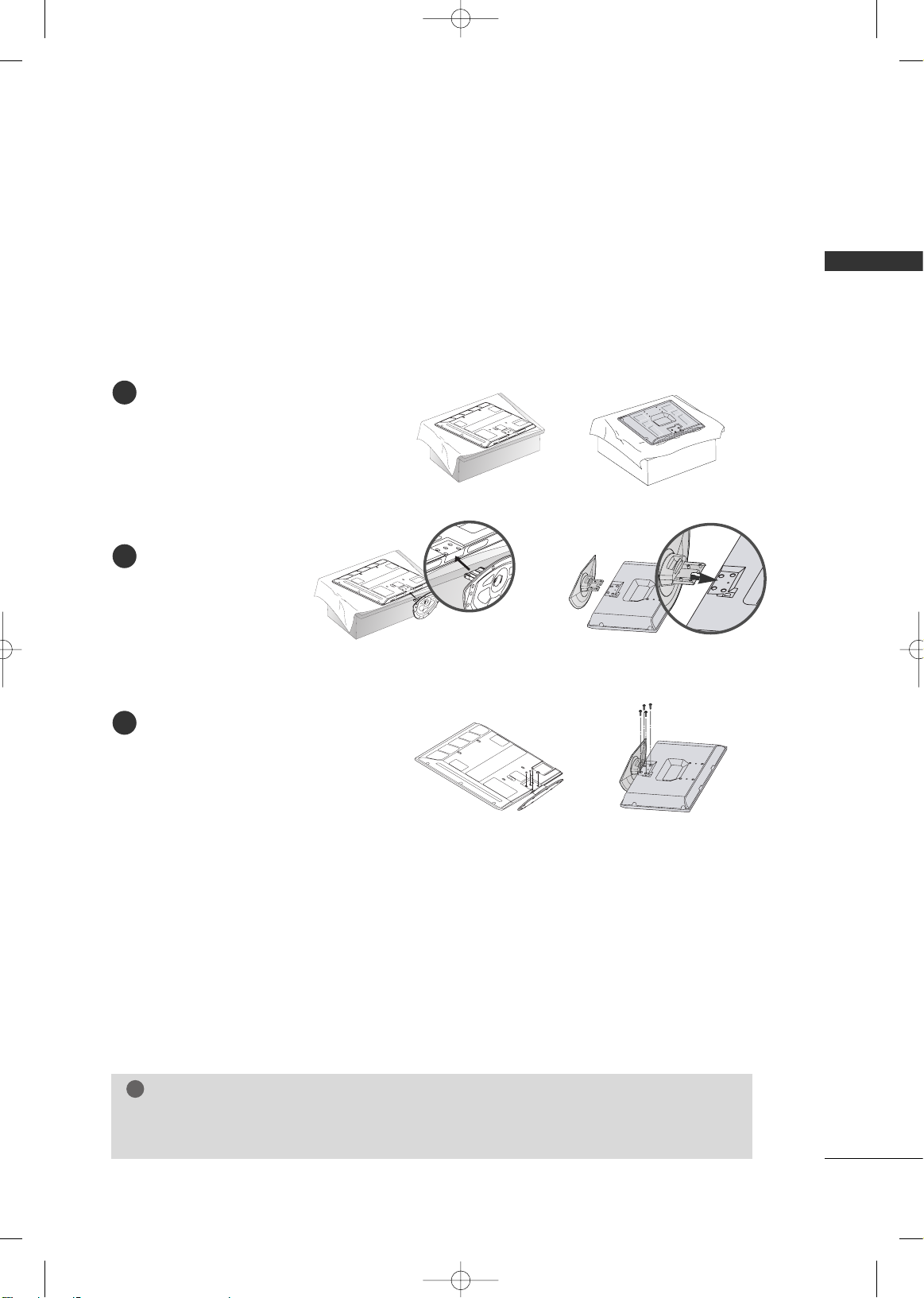
PREPARATION
13
STAND INSTALLATION
■
Image shown may differ from your TV
Plasma TV Model ( Only 42PG20*
, 32PC5**)
Carefully place the TV screen side down on
a cushioned surface to protect the screen
from damage.
Assemble the TV as shown.
Fix the 4 bolts securely using the holes in
the back of the TV.
1
2
3
GG
When assembling the desk type stand, check whether the bolt is fully tightened. (If not tightened
fully, the product can tilt forward after the product installation). If you tighten the bolt with excessive
force, the bolt can deviate from abrasion of the tightening part of the bolt.
NOTE
!
MFL41469207en-Edit1 8/22/08 8:54 AM Page 13
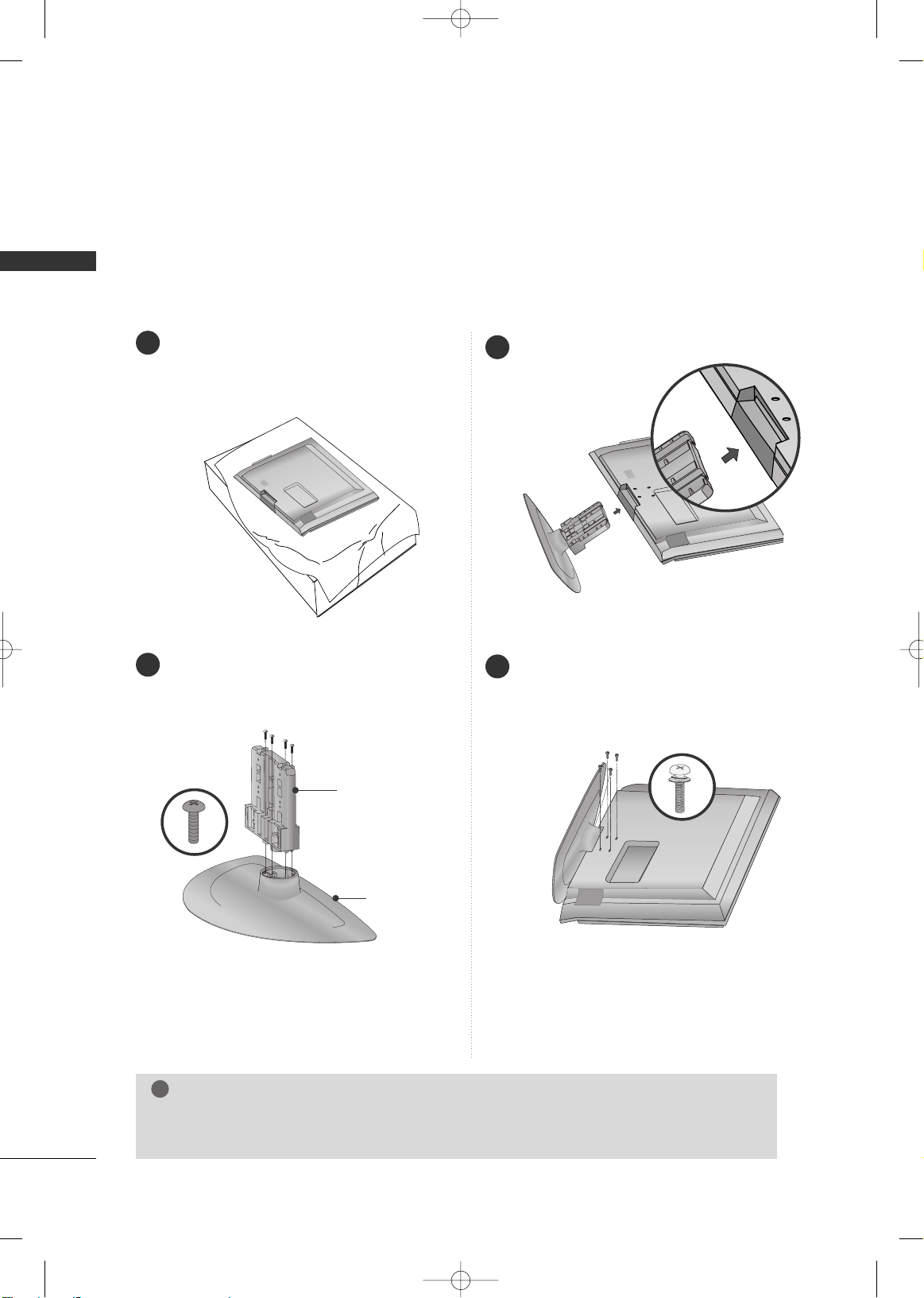
PREPARATION
14
PREPARATION
Carefully place the TV screen side down on a
cushioned surface to protect the screen from
damage.
Assemble the parts of the
SStt aanndd BBoodd yy
with
the
CCoo vveerr BBaa ssee
of the TV.
Assemble the TV as shown.
1
2
3
Fix the 4 bolts securely using the holes in the
back of the TV.
4
SSTTAANN DD BBOO DDYY
CCOOVVEERR BBAASSEE
LCD TV Models
(Except 47LG30*)
GG
When assembling the desk type stand, check whether the bolt is fully tightened. (If not tightened
fully, the product can tilt forward after the product installation). If you tighten the bolt with excessive
force, the bolt can deviate from abrasion of the tightening part of the bolt.
NOTE
!
MFL41469207en-Edit1 8/22/08 8:54 AM Page 14
PREPARATION
15
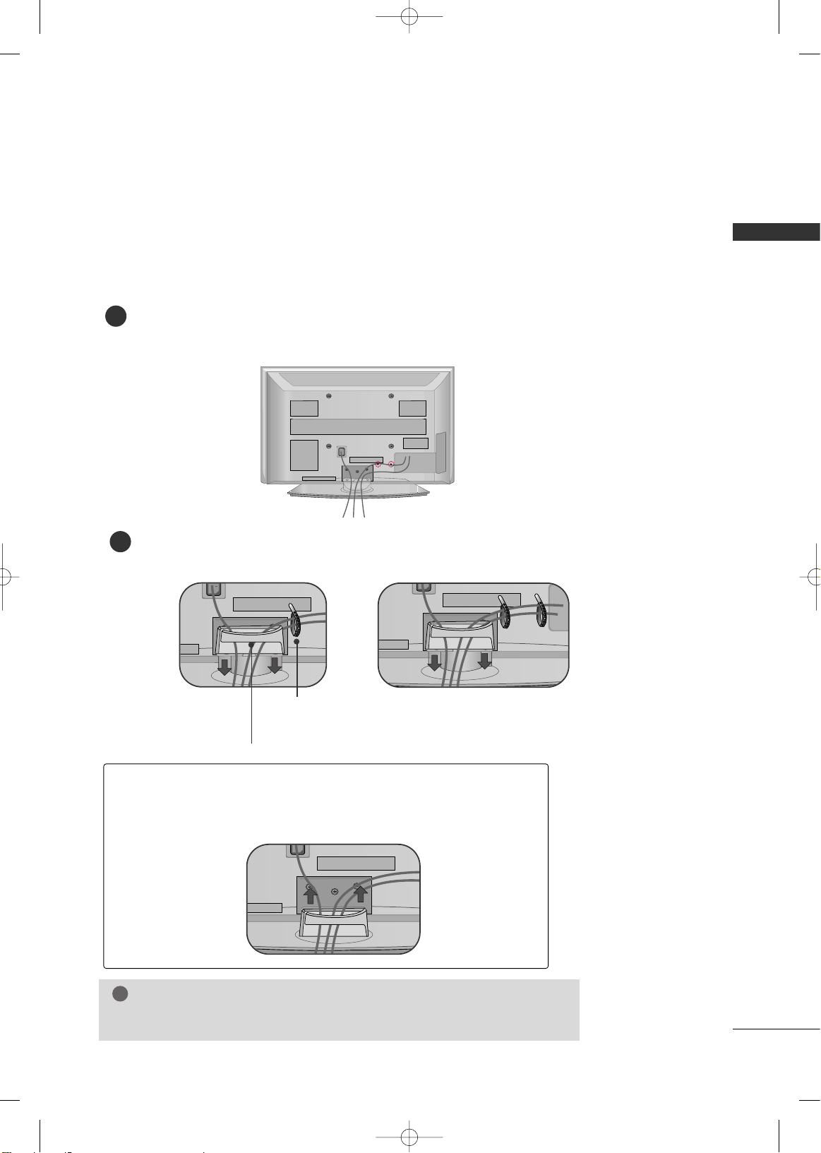
CABLE MANAGEMENT
■
Here shown may be somewhat different from your TV.
Plasma TV Models (Only 42/50PG20*)
GG
Do not hold the CABLE MANAGEMENT CLIP when moving the TV.
- If the TV is dropped, you may be injured or the product may be broken.
NOTE
!
Connect the cables as necessary.
To connect additional equipment, see the EXTERNAL EQUIPMENT SETUP section.
1
Install the CABLE MANAGEMENT CLIP as shown.
If your TV has CABLE HOLDER, fix it as shown and bundle the cables.
2
How to remove the
CABLE MANAGEMENT CLIP
GG
Hold the CABLE MANAGEMENT CLIP with both hands and pull it upward.
CABLE MANAGEMENT CLIP
CABLE HOLDER
42PG20*
50PG20*
MFL41469207en-Edit1 8/22/08 8:54 AM Page 15

PREPARATION
16
PREPARATION
LCD TV Model
Connect the cables as necessary.
To connect additional equipment, see the EXTERNAL EQUIPMENT SETUP section.
Install the CABLE MANAGEMENT CLIP as shown.
CABLE MANAGEMENT CLIP
1
2
Put the cables inside the CABLE MANAGEMENT CLIP and snap it closed.
3
Plasma TV Models ( Only
32PC5**)
Arrange the cables as shown picture.
MFL41469207en-Edit1 8/22/08 8:54 AM Page 16

PREPARATION
17
SECURING THE TV TO THE WALL FALL OVER.
This feature is not available for all models.
Here shown may be somewhat different from your TV.
■
Position the TV close to the wall to avoid the possibility of it falling when pushed.
■
The instructions shown below are a safer way to set up the TV, which is to fix it to the wall, avoiding the
possibility of it falling forwards if pulled. This will prevent the TV from falling forward and causing injury.
This will also prevent the TV from damage. Ensure that children do not climb or hang from the TV.
■
You should purchase necessary components to prevent TV from falling off of the stand.
■
Insert the eye-bolts (or TV brackets and bolts) to tighten the product to the wall as shown in the picture.
*If your product has the bolts in the eye-bolts position before inserting the eye-bolts, loosen the bolts.
Secure the wall brackets with the bolts (not provided as parts of the product, must purchase separately) to
the wall. Match the height of the bracket that is mounted on the wall to the holes in the product.
Ensure the eye-bolts or brackets are tightened securely.
■
Use a sturdy rope (not provided as parts of the product, must purchase separately) to tie the product. It is safer to tie the rope so it
becomes horizontal between the wall and the product.
NOTE
!
G
When moving the TV undo the cords first.
G
Use a platform or cabinet strong and large enough to support the size and weight of the TV.
G
To use the TV safely make sure that the height of the bracket on the wall and on the TV is the same.
MFL41469207en-Edit1 8/22/08 8:54 AM Page 17
PREPARATION
18
PREPARATION
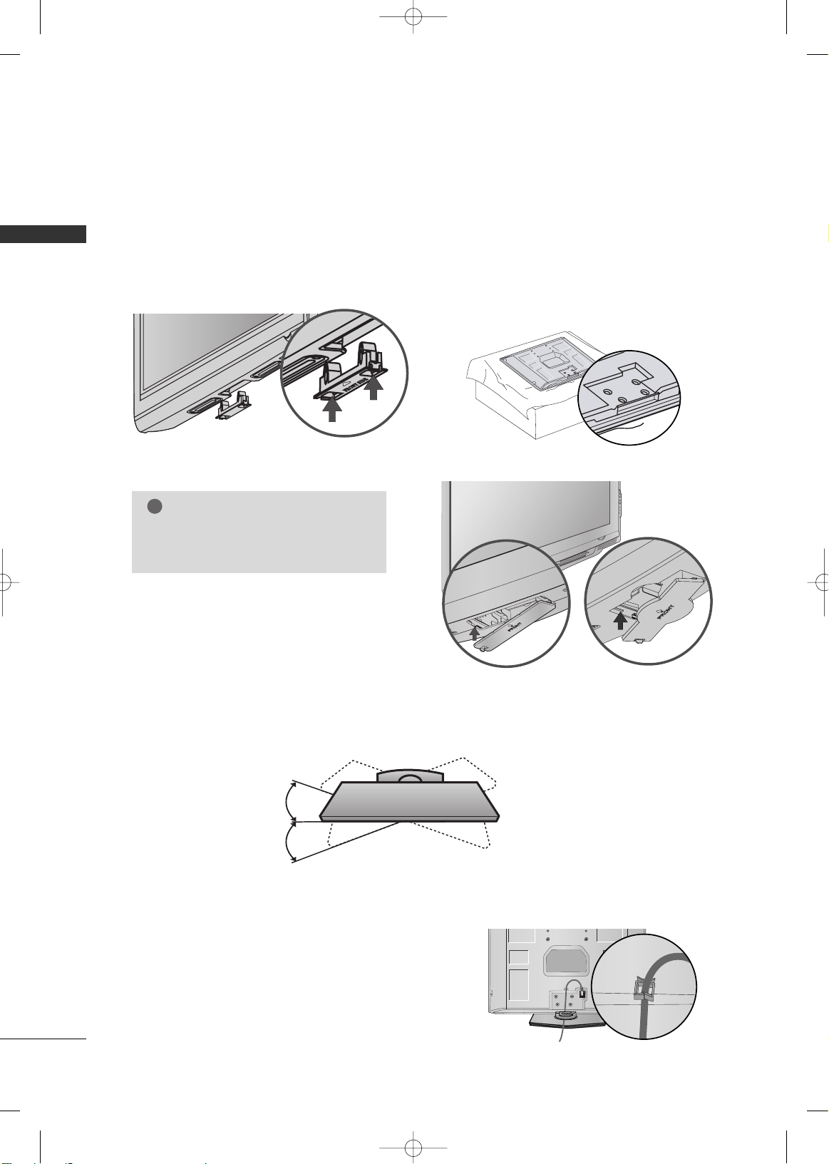
SWIVEL STAND
After installing the TV, you can adjust the TV set manually to the left or right direction by 20 degrees to suit
your viewing position.
PROTECTION COVER
LCD TV Model
■
Image shown may differ from your TV.
After removing the stand, install the included
pprr ootteeccttiioo nn cc oovveerr
over the hole for the stand.
Press the
PPRROOTTEECCTTIIOONN CCOOVVEERR
into the TV until you hear it click.
Detech the protection cover after pressing the
left/right buttons.
Plasma TV Models
NOTE
!
G
Not to occur the vibration or noise, fix
the protection cover using bolts(provided as parts of the product).
POWER CORD ARRANGEMENT
( Only
32PC5**)
After connecting the power cord to the AC input
terminal, fix the power cord at the rear side Hole of
the TV by using the bracket for fixing the power
cord.
MFL41469207en-Edit1 8/22/08 8:54 AM Page 18

PREPARATION
19
WALL MOUNT: HORIZONTAL INSTALLATION
For adequate ventilation allow a clearance of 4” (10cm) all around the TV. We recommend that you
use an LG brand wall mount when mounting the TV to a wall.
■
This part mainly use picture for Plasma TV model.
4 inches
4 inches
4 inches
4 inches
4 inches
ATTACHING THE TV TO A DESK (Only 26/32/42LG30*, 32/42LG50**)
If you wish to attach the TV to a desk, it must be securely fastened to the desk using a metal screw (as shown
below). Failure to securely attach the TV may result in the TV falling: which may cause damage to the TV and
serious personal injury.
1-Screw
(provided as parts of the product)
Desk
Stand
DESKTOP PEDESTAL INSTALLATION
For adequate ventilation allow a clearance of 4” (10cm) all around the TV.
4 inches
4 inches
4 inches
4 inches
GG
Ensure adequate ventilation by following the clearance recommendations.
GG
Do not mount near or above any type of heat source.
CAUTION
MFL41469207en-Edit1 8/22/08 8:54 AM Page 19
PREPARATION
20
PREPARATION
ANTENNA
AV IN 2
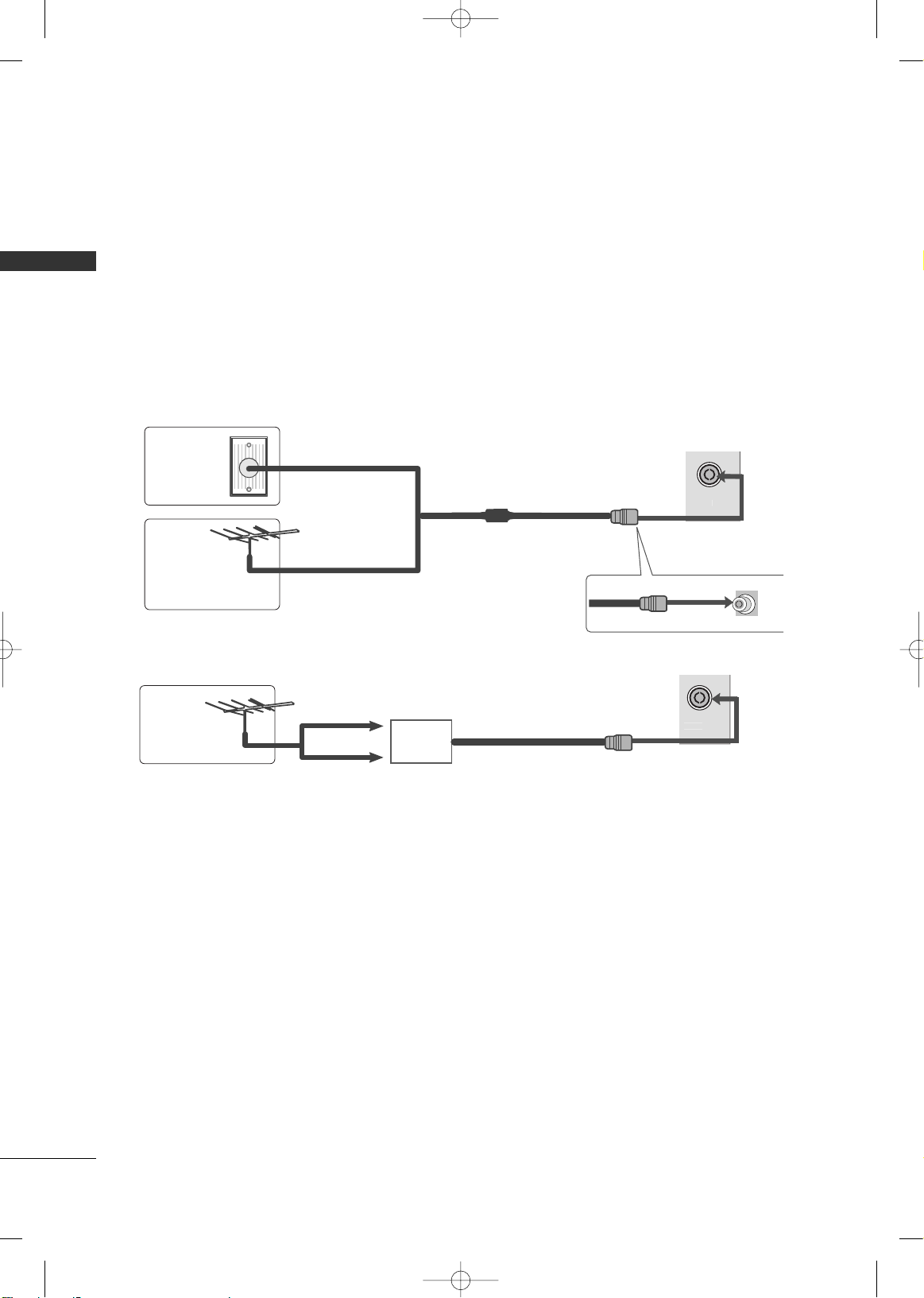
ANTENNA CONNECTION
■
For optimum picture quality, adjust antenna direction.
■
An antenna cable and converter are not supplied.
Multi-family Dwellings/Apartments
(Connect to wall antenna socket)
Single-family Dwellings /Houses
(Connect to wall jack for outdoor antenna)
Outdoor
Antenna
Wall
Antenna
Socket
RF Coaxial Wire (75 ohm)
Antenna
UHF
VHF
■
In poor signal areas, to achieve better picture quality it may be necessary to install a signal amplifier to the
antenna as shown above.
■
If signal needs to be split for two TVs, use an antenna signal splitter for connection.
■
To prevent damage do not connect to the mains outlet until all connections are made between the devices.
ANTENNA
AV IN 2
Signal
Amplifier
MFL41469207en-Edit1 8/22/08 8:54 AM Page 20
EXTERNAL EQUIPMENT SETUP
21
EXTERNAL EQUIPMENT SETUP
HDMI IN HDMI DVI IN
HDMI/DVI IN
1
1
2
COMPONENT IN
VIDEO
AUDIO
L/MONO
R
AUDIO
VIDEO
1 2
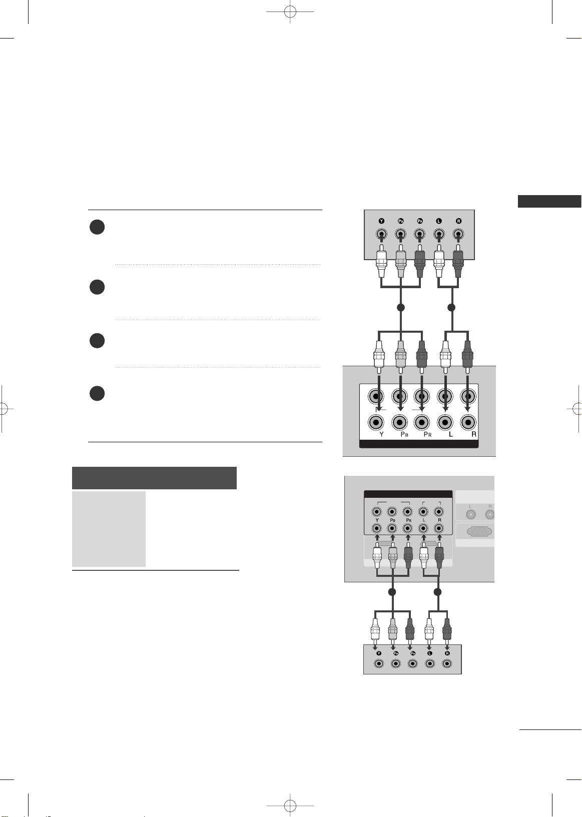
HD RECEIVER SETUP
When connecting with a component cable
Connect the video outputs (Y, PB, PR
)
of the digital set
top box to the
CCOOMMPPOONNEENN TT IINN VVIIDDEEOO
jacks on the
TV.
Connect the audio output of the digital set-top box to
the
CCOOMMPPOONNEENN TT IINN AAUUDDIIOO
jacks on the TV.
Turn on the digital set-top box.
(
Refer to the owner’s manual for the digital set-top box.
)
Select
CC oommppoonneenntt11
input source using the
IINN PPUUTT
button on the remote control.
If connected to
CCOOMMPPOONNEENNTT IINN22
, select
CC oommppoonneenntt22
input source.
2
3
4
1
■
To avoid damaging any equipment, never plug in any power cords until you have finished connecting all equipment.
■
This section on EXTERNAL EQUIPMENT SETUP mainly uses diagrams for the Plasma TV models.
■
Image shown may differ from your TV.
Signal
480i/576i
480p/576p
720p/1080i
10 8 0 p
Component
Yes
Yes
Yes
Yes
(Only 50Hz, 60Hz)
VIDEOVIDEO
AUDIO
COMPONENTCOMPONENT IN IN
1 2
RGB IN (PC)RGB IN (PC)
ANTENNA
IN
1
2
AUDIO IN
(RGB/DVI)
AV OUT
AV IN
VIDEO
AUDIO
COMPONENT IN
1
2
12
AUDIO IN
(RGB/DVI)
HDMI INHDMI/DVI INHDMI/DVI IN
HDMI INHDMI/DVI IN
RS-232C IN
(CONTROL & SERVVICE)
VARIABLE AUDIO OUT
RGB IN (PC)
RS-232C IN
(CONTROL & SERVICE)
ANTENNA
IN
AV OUT
AV IN
VARIABLE AUDIO OUT
1 2
or
MFL41469207en-Edit1 8/22/08 8:54 AM Page 21

EXTERNAL EQUIPMENT SETUP
22
EXTERNAL EQUIPMENT SETUP
HDMI IN HDMI DVI IN
HDMI/DVI IN
1
HDMI IN HDMI IN HDMI DVI IN HDMI DVI IN
HDMI IN HDMI/DVI IN
1 2
L/MONO
R
AUDIO
VIDEO
L/L/MONOMONO
R
AUDIOAUDIO
IN 1
VIDEOVIDEO
OUT
VARIABLE AUDIO
AV
1
When connecting with a HDMI cable
Connect the HDMI output of the digital set-top box to
the
HHDDMMII//DD VVII IINN 11,, HHDDMMII IINN 22
or
HHDDMMII IINN
33
(Only 32/42LG50**) jack on the TV.
Select
HHDDMMII11//DD VV II ,, HH DDMM II 22
or
HHDDMMII 33
(Only
32/42LG50**) input source using the
IINN PPUUTT
button
on the remote control.
Turn on the digital set-top box.
(
Refer to the owner’s manual for the digital set-top box.
)
2
3
1
GG
TV can receive the video and audio signal simultaneously with using a HDMI cable.
NOTE
!
Resolution
720x480
720x576
1280x720
1920x1080i
1920x1080p
HDMI-DTV mode
Horizontal Vertical
Frequency(kHz) Frequency(Hz)
31.47 59.94
31.50 60.00
31.25 50.00
44.96 59.94
45.00 60.00
37.50 50.00
33.72 59.94
33.75 60.00
28.125 50.00
67.432 59.94
67.50 60.00
56.25 50.00
27. 0 24. 00
33.75 30.00
Plasma TV Models
LCD TV Models
Resolution
720x480
720x576
1280x720
1920x1080i
1920x1080p
Horizontal Vertical
Frequency(kHz) Frequency(Hz)
31.47 59.94
31.50 60.00
31.25 50.00
44.96 59.94
45.00 60.00
37.50 50.00
33.72 59.94
33.75 60.00
28.125 50.00
67.432 59.94
67.50 60.00
56.25 50.00
27.00 24.00
33.75 30.00
VIDEO
AUDIO
COMPONENT IN
12
RGB IN (PC)
ANTENNA
IN
1
2
AUDIO IN
(RGB/DVI)
AV OUT
AV IN
VIDEO
AUDIO
COMPONENT IN
1
2
1 2
VIDEO
AUDIO
COMPONENT IN
1
2
12
AUDIO IN
(RGB/DVI)
HDMI INHDMI/DVI IN
HDMI INHDMI/DVI INHDMI/DVI IN
HDMI INHDMI/DVI IN
RS-232C IN
(CONTROL & SERVICE)
VARIABLE AUDIO OUT
RGB IN (PC)
RS-232C IN
(CONTROL & SERVICE)
ANTENNA
IN
AV OUT
AV IN
VARIABLE AUDIO OUT
ANTENNA
IN
AV OUT
AV IN
VARIABLE AUDIO OUT
RGB IN (PC)RGB IN (PC)
AUDIO IN
(RGB/DVI)
RS-232C IN
(CONTROL & SERVICE)
1
or
MFL41469207en-Edit1 8/22/08 8:54 AM Page 22
EXTERNAL EQUIPMENT SETUP
23
HDMI IN HDMI IN HDMI DVI IN HDMI DVI IN
HDMI/DVI IN
1
AUDIO
(RGB/DVI)
RGB
(PC)
RGB IN
RS-232C IN
(CONTROL)
L/L/MONOMONO
R
AUDIOAUDIO
IN 1
VIDEOVIDEO
OUT
VARIABLE AUDIO
1
2
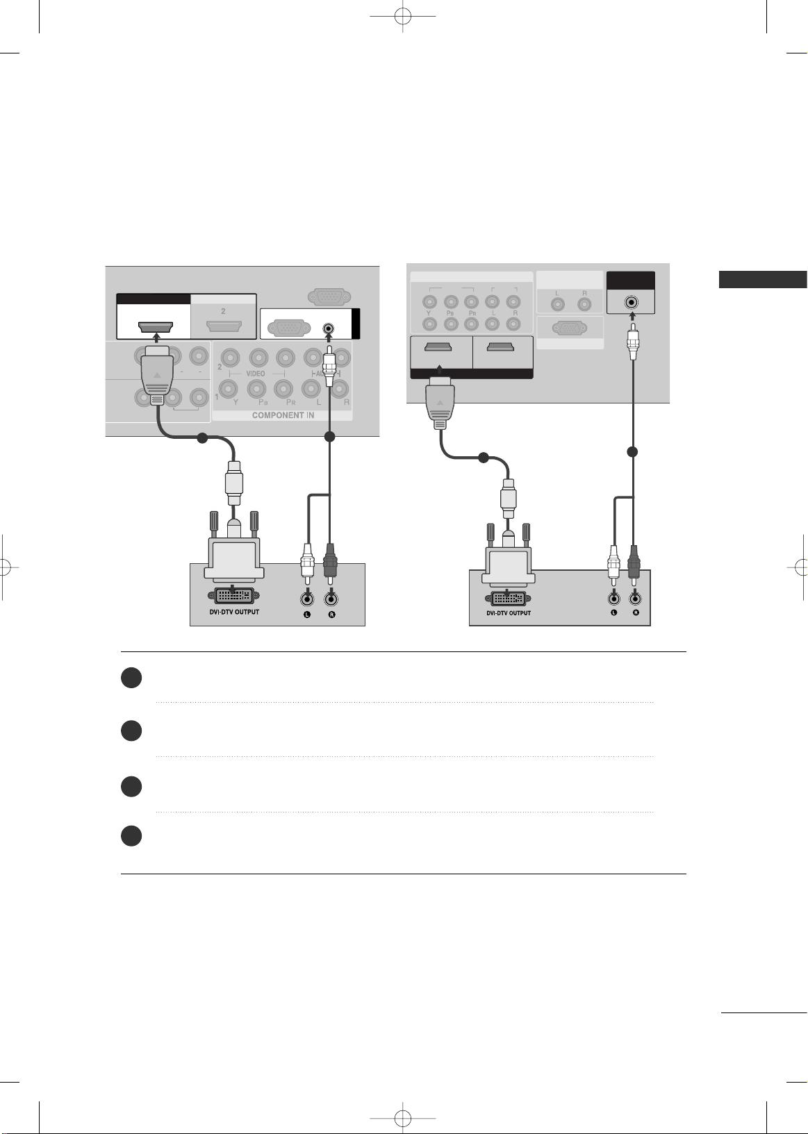
Connect the DVI output of the digital set-top box to the
HHDDMMII//DD VVII II NN 11
jack on the TV.
Connect the audio output of the digital set-top box to the
AAUU DDIIOO((RRGGBB//DDVVII))
jack on the TV.
Turn on the digital set-top box. (Refer to the owner’s manual for the digital set-top box.
)
Select
HHDDMMII11//DDVVII
input source using the
IINN PPUUTT
button on the remote control.
2
3
4
1
When connecting with a HDMI to DVI cable
VIDEOVIDEO
AUDIO
COMPONENTCOMPONENT IN IN
1
2
1 2
AUDIO INAUDIO IN
(RGB/DVI)(RGB/DVI)
HDMI INHDMI INHDMI/DVI IN
RGB IN (PC)RGB IN (PC)
RS-232C IN
(CONTROL & SERVICE)
ANTENNA
IN
AV OUT
AV IN
VARIABLE AUDIO OUT
2
1
or
MFL41469207en-Edit1 8/22/08 8:54 AM Page 23

EXTERNAL EQUIPMENT SETUP
24
EXTERNAL EQUIPMENT SETUP
1
2
COMPONENT IN
VIDEO
AUDIO
1 2
DVD SETUP
When connecting with a component cable
Component Input ports
To achieve better picture quality, connect a DVD player to the component input ports as shown below.
Component ports on the TV
YPB PR
Video output ports
on DVD player
Y
Y
Y
Y
P
B
B-Y
Cb
Pb
PR
R-Y
Cr
Pr
Connect the video outputs (Y, PB
, PR
)
of the DVD to the
CCOOMMPPOONNEENN TT IINN VVIIDDEEOO
jacks on the TV.
Connect the audio outputs of the DVD to the
CCOO MMPPOO--
NN EENNTT IINN AAUUDDIIOO
jacks on the TV.
Turn on the DVD player, insert a DVD.
Select
CC oommppoonneenntt11
input source using the
IINN PPUUTT
button on
the remote control.
If connected to
CCOOMMPPOONNEENNTT IINN22
, select Component
2 input source.
Refer to the DVD player's manual for operating instructions.
2
3
4
5
1
VIDEOVIDEO
AUDIOAUDIO
COMPONENTCOMPONENT IN IN
1 2
1
2
HDMI INHDMI IN
HDMI/DVI INHDMI/DVI IN
RGB IN RGB IN (PC)
ANTENNA
IN
AUDIO IN
(RGB/DVI)
AV OUT
AV IN
RS-232CRS-232C IN
(CONTROL(CONTROL & S & SERVICE)
VARIABLE AUDIO OUT
1 2
or
MFL41469207en-Edit1 8/22/08 8:54 AM Page 24

EXTERNAL EQUIPMENT SETUP
25
When connecting with an S-Video cable
(Except 32PC5**)
Connect the S-VIDEO output of the DVD to the
SS --
VVIIDDEEOO
input on the TV.
Connect the audio outputs of the DVD to the
AAUUDDIIOO
input jacks on the TV.
Turn on the DVD player, insert a DVD.
Select
AAVV22
input source using the
IINN PPUUTT
button on
the remote control.
Refer to the DVD player's manual for operating
instructions.
2
3
4
5
1
AV IN 2V IN 2
L R
S-VIDEOVIDEO
OUTPUT
SWITCH
ANT IN
ANT OUT
1
2
MFL41469207en-Edit1 8/22/08 8:54 AM Page 25
EXTERNAL EQUIPMENT SETUP
26
EXTERNAL EQUIPMENT SETUP
VIDEOVIDEO
AUDIO
COMPONENTCOMPONENT IN
1
2
1 2
VIDEO
AUDIO
COMPONENT IN
1
2
12
VIDEO
AUDIO
COMPONENT IN
12
1
2
HDMI IN
HDMI/DVI IN
HDMI INHDMI INHDMI/DVI INHDMI/DVI IN
HDMI INHDMI/DVI IN
RGB IN (PC)
ANTENNA
IN
AUDIO IN
(RGB/DVI)
AV OUT
AV IN
RS-232C IN
(CONTROL & SERVICE)
VARIABLE AUDIO OUT
RGB IN (PC)
ANTENNA
IN
AUDIO IN
(RGB/DVI)
AV OUT
AV IN
RS-232C IN
(CO(CONTROL & SERVICE)
VARIABLE AUDIO OUT
1
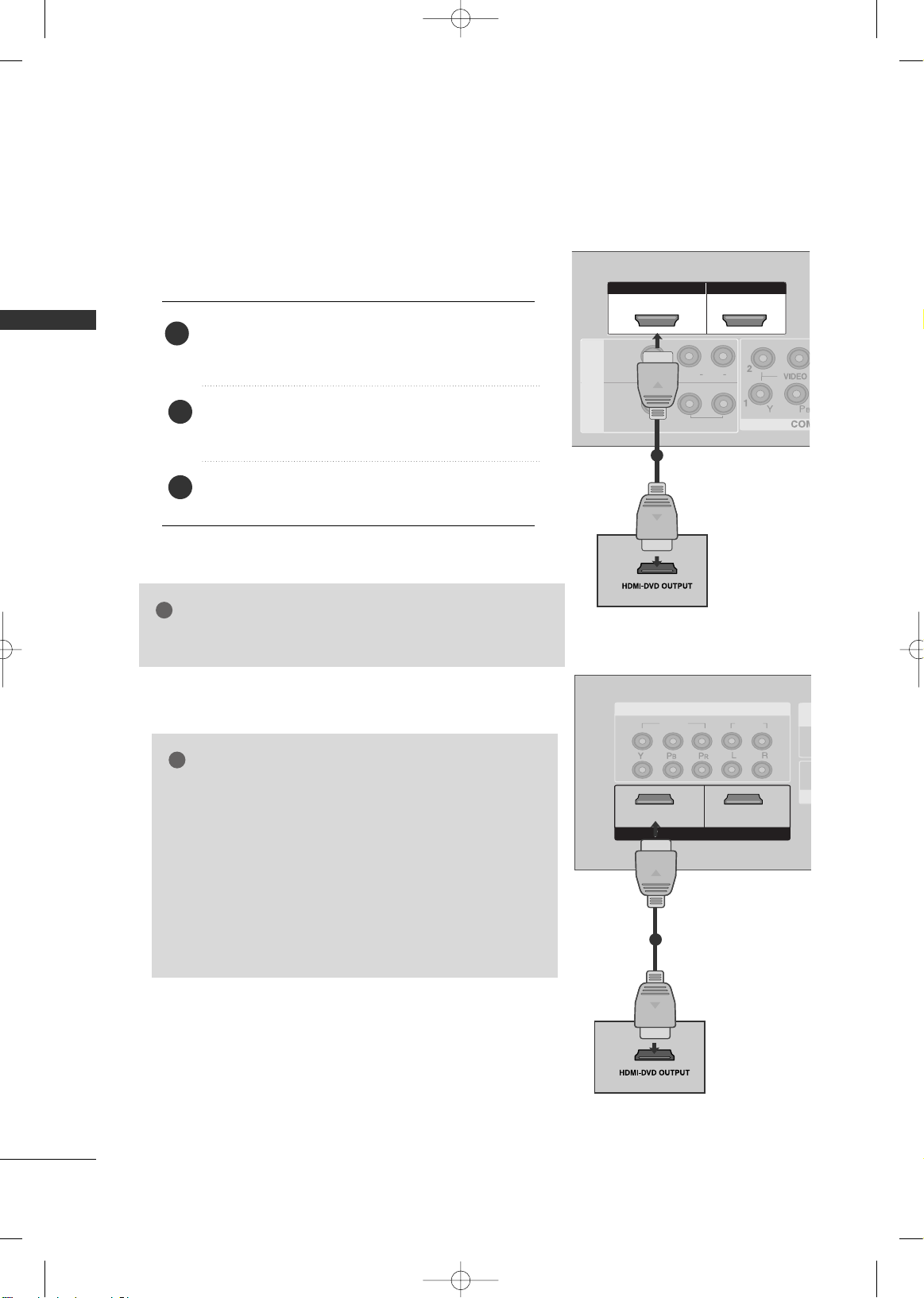
When connecting HDMI cable
Connect the HDMI output of the DVD to the
HHDDMM II // DDVVII IINN 11,, HHDD MMII IINN 22
or
HHDDMMII IINN 33
(Only
32/42LG50**) jack on the TV.
Select
HHDDMMII11//DD VV II ,, HH DDMM II 22
or
HHDDMMII 33
(Only
32/42LG50**) input source using the
IINN PPUUTT
button
on the remote control.
Refer to the DVD player's manual for operating instructions.
1
GG
The TV can receive video and audio signals simultaneously
when using a HDMI cable.
NOTE
!
2
3
GG
TV can receive the video and audio signal simultaneously
with using a HDMI cable.
GG
If the DVD supports Auto HDMI function, the output resolution of the source device will be automatically set to
1280x720p.
GG
If the DVD player does not support Auto HDMI, you need to
set the DVD output resolution appropriately.
To get the best picture quality, adjust the output resolution of
the source device to 1280x720p.
(32/42LG50
**
:1920x1080i/1080p).
NOTE
!
or
HDMI IN HDMI DVI IN
HDMI IN HDMI IN HDMI/DVI IN HDMI/DVI IN
1 2
HDMI IN HDMI DVI IN
AV IN 2
L/L/MONOMONO
R
AUDIOAUDIO
IN 1
VIDEOVIDEO
OUT
VARIABLE AUDIO
AV
( )
1
MFL41469207en-Edit1 8/22/08 8:54 AM Page 26
 Loading...