

LG 42LE5500-DA Service Manual

INPUT
MENU
P
OK
/I
LED LCD TV
SERVICE MANUAL
CAUTION
BEFORE SERVICING THE CHASSIS,
READ THE SAFETY PRECAUTIONS IN THIS MANUAL.
CHASSIS : LT03E
MODEL : 42LE5500 42LE5500-DA
North/Latin America http://aic.lgservice.com
Europe/Africa http://eic.lgservice.com
Asia/Oceania http://biz.lgservice.com
Internal Use Only
Printed in KoreaP/NO : MFL63283601 (1003-REV00)

- 2 -
LGE Internal Use OnlyCopyright LG Electronics. Inc. All right reserved.
Only for training and service purposes
CONTENTS
CONTENTS .............................................................................................. 2
SPECIFICATION....................................................................................... 3
ADJUSTMENT INSTRUCTION ................................................................ 7
EXPLODED VIEW .................................................................................. 17
SVC. SHEET ...............................................................................................
- 3 -
LGE Internal Use OnlyCopyright LG Electronics. Inc. All right reserved.
Only for training and service purposes
SAFETY PRECAUTIONS
Many electrical and mechanical parts in this chassis have special safety-related characteristics. These parts are identified by in the
Schematic Diagram and Exploded View.
It is essential that these special safety parts should be replaced with the same components as recommended in this manual to prevent
Shock, Fire, or other Hazards.
Do not modify the original design without permission of manufacturer.
General Guidance
An isolation Transformer should always be used during the
servicing of a receiver whose chassis is not isolated from the AC
power line. Use a transformer of adequate power rating as this
protects the technician from accidents resulting in personal injury
from electrical shocks.
It will also protect the receiver and it's components from being
damaged by accidental shorts of the circuitry that may be
inadvertently introduced during the service operation.
If any fuse (or Fusible Resistor) in this TV receiver is blown,
replace it with the specified.
When replacing a high wattage resistor (Oxide Metal Film Resistor,
over 1 W), keep the resistor 10 mm away from PCB.
Keep wires away from high voltage or high temperature parts.
Before returning the receiver to the customer,
always perform an AC leakage current check on the exposed
metallic parts of the cabinet, such as antennas, terminals, etc., to
be sure the set is safe to operate without damage of electrical
shock.
Leakage Current Cold Check(Antenna Cold Check)
With the instrument AC plug removed from AC source, connect an
electrical jumper across the two AC plug prongs. Place the AC
switch in the on position, connect one lead of ohm-meter to the AC
plug prongs tied together and touch other ohm-meter lead in turn to
each exposed metallic parts such as antenna terminals, phone
jacks, etc.
If the exposed metallic part has a return path to the chassis, the
measured resistance should be between 1 MΩ and 5.2 MΩ.
When the exposed metal has no return path to the chassis the
reading must be infinite.
An other abnormality exists that must be corrected before the
receiver is returned to the customer.
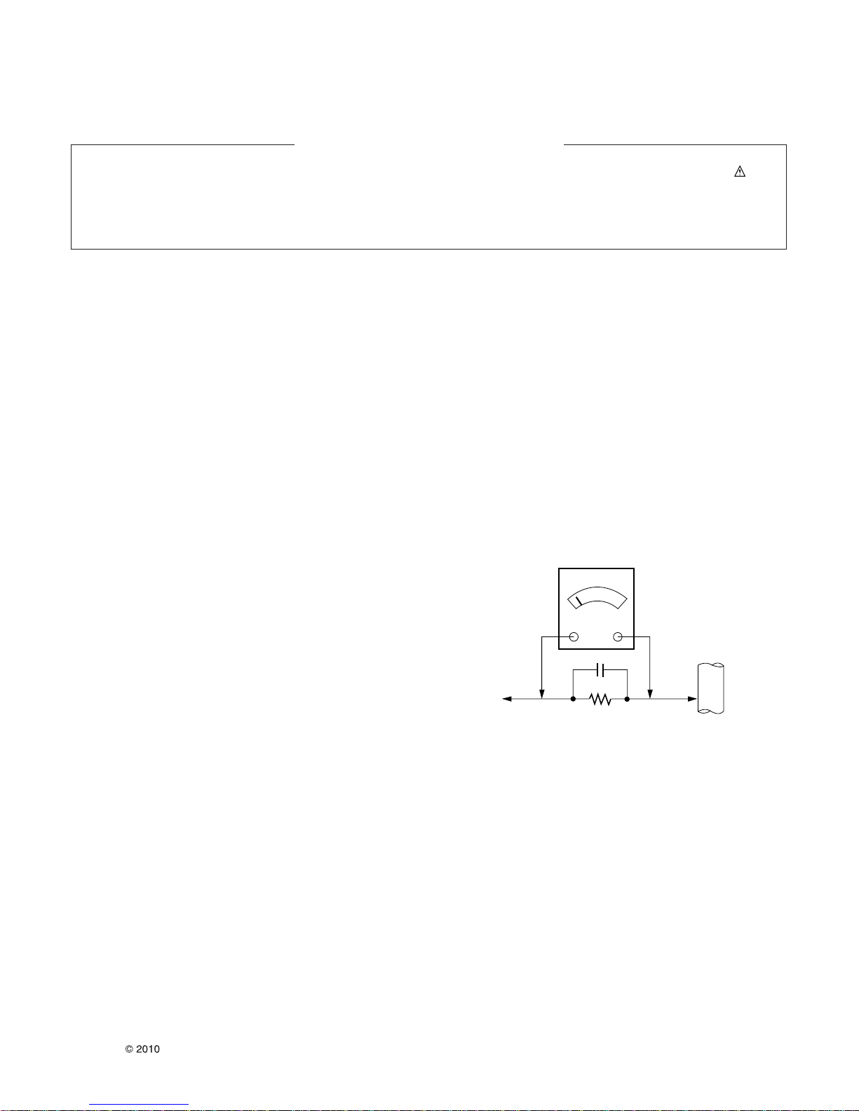
Leakage Current Hot Check (See below Figure)
Plug the AC cord directly into the AC outlet.
Do not use a line Isolation Transformer during this check.
Connect 1.5 K / 10 watt resistor in parallel with a 0.15 uF capacitor
between a known good earth ground (Water Pipe, Conduit, etc.)
and the exposed metallic parts.
Measure the AC voltage across the resistor using AC voltmeter
with 1000 ohms/volt or more sensitivity.
Reverse plug the AC cord into the AC outlet and repeat AC voltage
measurements for each exposed metallic part. Any voltage
measured must not exceed 0.75 volt RMS which is corresponds to
0.5 mA.
In case any measurement is out of the limits specified, there is
possibility of shock hazard and the set must be checked and
repaired before it is returned to the customer.
Leakage Current Hot Check circuit
1.5 Kohm/10W
To Instrument’s
exposed
METALLIC PARTS
Good Earth Ground
such as WATER PIPE,
CONDUIT etc.
AC Volt-meter
When 25A is impressed between Earth and 2nd Ground
for 1 second, Resistance must be less than 0.1
*Base on Adjustment standard
IMPORTANT SAFETY NOTICE
0.15 uF
Ω

- 4 -
LGE Internal Use OnlyCopyright LG Electronics. Inc. All right reserved.
Only for training and service purposes
SPECIFICATION
NOTE : Specifications and others are subject to change without notice for improvement
.
4. Module General Specification
1. Application range
This specification is applied to the LCD TV used
LT03B/D/E/N/T/S chassis.
2. Requirement for Test
Each part is tested as below without special appointment.
1) Temperature: 25 ºC ± 5 ºC(77 ºF ± 9 ºF), CST: 40 ºC ± 5 ºC
2) Relative Humidity : 65 % ± 10 %
3) Power Voltage
: Standard input voltage (AC 100-120 V~ 50 / 60 Hz)
* Standard Voltage of each products is marked by models.
4) Specification and performance of each parts are followed
each drawing and specification by part number in
accordance with BOM.
5) The receiver must be operated for about 20 minutes prior to
the adjustment.
3. Test method
1) Performance: LGE TV test method followed
2) Demanded other specification
- Safety : CE, IEC specification
- EMC :CE, IEC
No. Item Specification Remark
1 Display Screen Device 105 cm(42 inch) wide color display module
2 Aspect Ratio 16:9
3 LCD Module 105 cm(42 inch) TFT WUXGA LCD
4 Operating Environment Temp. : 0 deg ~ 40 deg
Humidity : 0 % ~ 85 %
5 Storage Environment Temp. : -20 deg ~ 60 deg
Humidity : 0 ~ 85 %
6 Input Voltage AC 100-240V~, 50 / 60Hz
7 Power Consumption 98 FHD, 120Hz(Edge LED) LC420EUH-SCA1/2 - LE5500, LE7500
=LCD(Module)+Backlight(LED)
8 Module Size 973.2(H) x 566.2(V) x 10.8 mm(D) LC420EUH-SCA1/2 - LE5500, LE7500
8 Pixel Pitch 0.4845 (H) x 0.4845 (V) LC420EUH-SCA1/2 - LE5500, LE7500
9 Back Light CCFL/Edge-LED/IOP-LED
10 Display Colors 1.06 B(true) colors (10-bit)
11 Coating 3H(Hard coating), Anti-glare
- 5 -
LGE Internal Use OnlyCopyright LG Electronics. Inc. All right reserved.
Only for training and service purposes
5. Chroma & Brightness
6. Component Video Input (Y, C
B/PB, CR/PR)
No.
Specification
Proposed
Resolution H-freq(kHz) V-freq(Hz) Pixel clock(MHz)
1. 720*480 15.73 59.94 13.500 SDTV, DVD 480I(525I)
2. 720*480 15.75 60.00 13.514 SDTV, DVD 480I(525I)
3. 3. 720*576 15.625 50.00 13.500 SDTV, DVD 576I(625I) 50Hz
4. 720*480 31.47 59.94 27.000 SDTV 480P
5. 720*480 31.50 60.00 27.027 SDTV 480P
6. 720*576 31.25 50.00 27.000 SDTV 576P 50Hz
7. 1280*720 44.96 59.94 74.176 HDTV 720P
8. 1280*720 45.00 60.00 74.250 HDTV 720P
9. 1280*720 37.50 50.00 74.25 HDTV 720P 50Hz
10. 1920*1080 28.125 50.00 74.250 HDTV 1080I 50Hz,
11. 1920*1080 33.72 59.94 74.176 HDTV 1080I
12. 1920*1080 33.75 60.00 74.25 HDTV 1080I
13. 1920*1080 56.25 50 148.5 HDTV 1080P
14. 14 1920*1080 67.432 59.94 148.350 HDTV 1080P
15. 1920*1080 67.5 60.00 148.5 HDTV 1080P
No. Item Specification Min. Typ. Max. Remark
1. Viewing Angle<CR>10> Right/Left/Up/Down 89/89/89/89 LC420EUH-SCA1/2
2. Luminance Luminance (cd/m
2
) 360 450 LC420EUH-SCA1/2
Variation 1.3 MAX /MIN
3. Contrast Ratio CR 1000 1400
4. CIE Color Coordinates White Wx 0.279 All white / All black
Wy 0.292
RED Xr 0.647
Yr Typ. 0.332 Typ.
Green Xg -0.03 0.309 +0.03
Yg 0.601
Blue Xb 0.149
Yb 0.059
No.
Specification
Proposed Remarks
Resolution H-freq(kHz) V-freq(Hz) Pixel Clock(MHz)
1. 640*350 31.468 70.09 25.17 EGA
2. 720*400 31.469 70.09 28.32 DOS
3. 640*480 31.469 59.94 25.17 VESA(VGA)
4. 800*600 37.879 60.317 40 VESA(SVGA)
5. 1024*768 48.363 60.004 65 VESA(XGA)
6. 1280*768 47.776 59.87 79.5 VESA(WXGA)
7. 1360*768 47.72 59.799 84.75 VESA(WXGA)
8. 1280*1024 63.668 59.895 109.00 SXGA Only FHD model
9. 1920*1080 66.587 59.934 138.50 WUXGA (Reduced Blanking) Only FHD model
7. RGB (PC)
- 6 -
LGE Internal Use OnlyCopyright LG Electronics. Inc. All right reserved.
Only for training and service purposes
8. HDMI Input
(1) DTV Mode
No. Resolution H-freq(kHz) V-freq.(Hz) Pixel clock(MHz) Proposed Remark
1. 640 480 31.469 59.94 25.17 VESA(VGA)
2. 800 600 37.879 60.317 40.00 VESA(SVGA)
3. 1024 768 48.363 60.004 65.00 VESA(XGA)
4. 1280 768 47.776 59.87 79.5 VESA(WXGA)
5. 1360 768 47.72 59.799 84.62 VESA(WXGA)
6. 1280 1024 63.595 60.00 108.875 SXGA
7. 1920 1080 66.647 59.988 138.625 WUXGA
(2) PC Mode
No. Resolution H-freq(kHz) V-freq.(Hz) Pixel clock(MHz) Proposed Remark
1. 720*480 15.73 59.94 13.500 SDTV, DVD 480I(525I) Spec. out but display.
2. 720*480 15.75 60.00 13.514 SDTV, DVD 480I(525I)
3. 720*576 15.625 50.00 13.500
SDTV, DVD 576I(625I) 50Hz
4. 720*480 31.47 59.94 27 SDTV 480P
5. 720*480 31.5 60.00 27.027 SDTV 480P
6. 720*576 31.25 50.00 27 SDTV 576P
7. 1280*720 44.96 59.94 74.176 HDTV 720P
8. 1280*720 45 60.00 74.25 HDTV 720P
9. 1280*720 37.5 50.00 74.25 HDTV 720P
10. 1920*1080 28.125 50.00 74.25 HDTV 1080I
11. 1920*1080 33.72 59.94 74.176 HDTV 1080I
12. 1920*1080 33.75 60.00 74.25 HDTV 1080I
13. 1920*1080 56.25 50.00 148.5 HDTV 1080P
14. 1920*1080 67.432 59.94 148.350 HDTV 1080P
15. 1920*1080 67.5 60.00 148.5 HDTV 1080P
16. 1920*1080 27 24.00 74.25 HDTV 1080P
17. 1920*1080 33.75 30.00 74.25 HDTV 1080P

- 7 -
LGE Internal Use OnlyCopyright LG Electronics. Inc. All right reserved.
Only for training and service purposes
ADJUSTMENT INSTRUCTION
1. Application Range
This specification sheet is applied to all of the LCD TV with
LT03B/D/E/H/R/S chassis.
2. Designation
(1) Because this is not a hot chassis, it is not necessary to use
an isolation transformer. However, the use of isolation
transformer will help protect test instrument.
(2) Adjustment must be done in the correct order.
(3) The adjustment must be performed in the circumstance of
25 ºC ± 5 ºC of temperature and 65 % ±10 % of relative
humidity if there is no specific designation.
(4) The input voltage of the receiver must keep AC 100-240
V~ 50 / 60Hz.
(5) Before adjustment, execute Heat-Run for 5 minutes at RF
no signal.
3. Adjustment items
3.1. PCB assembly adjustment items
1) Mac Address D/L & LAN Test
2) Main S/W program download : Using USB Memory stick
3) Input Tool - Option
4) Download EDID : EDID data are automatically
downloaded when adjusting the Tool Option.
5) ADC Calibration – RGB & Component
6) Check SW Version
3.2. SET assembly adjustment items
1) Input Area option.
2) Adjustment of White Balance : Auto
3) Adjustment of White Balance : Manual
4) Intelligent Sensor Inspection Guide
5) Blue-Tooth Inspection Guide
6) Local Dimming Inspection Guide
7) Preset CH information
8) Internal Press Test
9) Motion Remote controller Inspection
10) 3D Function test
11) Outgoing Condition Configuration
12) Sound spec
13) Factoring Option Data input.
4. PCB assembly adjustment method
4.1. MAC Address Download & LAN test
4.1.1. MAC Address D/L
A D/L Program : Serial.exe
4.1.1.1. Method
1) Connect Jig to PCBA.
1) Execute “ Serial.exe” on PC, MAC Address edit : Start /
End MAC address input
2) Connect Com-port.(Port connection button click)
3) Load button click(3) for MAC Address write
4) MAC address Write.
5) Check the OK Or NG
- 8 -
LGE Internal Use OnlyCopyright LG Electronics. Inc. All right reserved.
Only for training and service purposes
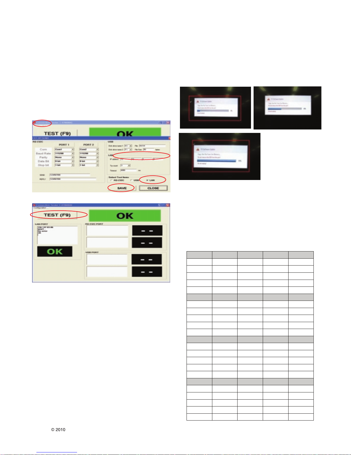
4.1.2. PING Test(LAN Operating Test)
4.1.2.1. Check PCBA
1) Connect LAN to PCBA& Power On.
2) Push ADJ key on Adjust remote-controller.
3) Enter “13. ACAP PING TEST” & check Network.
4.1.2.2. Check Set
1) Connect TV-Set & PC with Cross LAN cable.(PC IP :
12.12.2.3)
2) Execute “PINT Test program”, Check setting data of
program. (TV-Set IP : 12.12.2.2)
3) Push Power Only key on Adjust remote-controlle.
4) Click “RUN”, Check “OK” or “NG”
4.2. Main S/W program download
4.2.1. Using the Memory Stick
** USB DOWNLOAD : Service Mode
1) Insert the USB memory Stick to the USB port
2) Automatically detect the SW Version.
-> S/W download process is executed automatically.
3) Show the message “Copy the file from the Memory”
4) If the TV IS Turn On, Check the updated SW Version and
Tool Option.
4.3. Input tool option.
Adjust tool option refer to the BOM.
A Tool Option Input : PCBA Check Process
A Area Option Input : Set Assembly Process
*** Tool Option table
MODEL 55LE5500 47LE5500 42LE5500 32LE5500
Tool Option1 45312 33024 24832 16640
Tool Option2 32279 32279 32279 32279
Tool Option3 64556 64556 64556 64556
Tool Option4 25004 25004 25004 24876
Tool Option5 1851
1851
1851
1851
MODEL 55LE7500 47LE7500 42LE7500 32LE7500
Tool Option1 45344 33056 24864 16672
Tool Option2 32279 32279 32279 32279
Tool Option3 64556 64556 64556 64556
Tool Option4 25004 25004 25004 24876
Tool Option5 1851
1851
1851
1851
MODEL 55LE8500 47LE8500 42LE8500 32LE8500
Tool Option1 45376 33088 24896 16704
Tool Option2 32279 32279 32279 32279
Tool Option3 64572 64572
64572
64572
Tool Option4 25004 25004 25004 24876
Tool Option5 1851
1851
1851
1851
MODEL 55LX6500 47 LX6500 42LX6500
Tool Option1
Tool Option2 32279 32279 32279
Tool Option3 64572 64572
64572
Tool Option4 25004 25004 25004
Tool Option5 1979
1979
1979

- 9 -
LGE Internal Use OnlyCopyright LG Electronics. Inc. All right reserved.
Only for training and service purposes
After Input Tool Option and AC off
Before PCBA check, you have to change the Tool option and
have to AC off/on (Plug out and in)
(If missing this process, set can operate abnormally)
4.3.1. Profile : Must be changed the option value
because being different with some setting
value depend on module maker, inch and
market
4.3.2. Equipment : adjustment remote control.
4.3.3. Adjustment method
- The input methods are same as other chassis.(Use ADJ Key
on the Adjust Remocon.)
(If not changed the option, the input menu can differ the model
spec.)
Refer to Job Expression of each main chassis ass’y
(EBTxxxxxxxx) for Option value
Caution : Don’t Press “IN-STOP” key after completing the
function inspection.
4.4. EDID D/L method
Recommend that don’t connect HDMI and RGB(D-SUB) cable
when downloading the EDID. If not possible, recommend that
connect the MSPG equipment.
There are two methods of downloading the edid data
4.4.1. 1st Method
EDID datas are automatically downloaded when adjusting the
Tool Options. Automatically downloaded when pushing the
enter key after adjusting the tool option5. It takes about
2seconds.
4.4.2. 2nd Method
Caution : Must be checked that the tool option is right or not.
If tool option is wrong, hdmi edid data could not be
downloaded well.
1) Press the ADJ key
2) Move to the 10. EDID D/L and Press the right direction
key(
G)
3) Press the right direction key(
G) at Start.
4) After about a few seconds, appear “Waiting..” => “OK”, then
compele.
4.4.3. RS-232C command Method
1) Command : AE 00 10
Caution : Don’t connect HDMI and RGB(D-SUB) cable when
downloading the EDID.
If the cables are connected, Downloading of edid
could be failed.
4.4.4. EDID data
4.4.4.1. LT03B/D/E M0DEL
**
HDMI 3 : 256Bytes
0 1 2 3 4 5 6 7 8 9 A B C D E F
0
00 FF FF FF FF FF FF 00 1E 6D 01 00 01 01 01 01
10
01 14 01 03 80 10 09 78 0A EE 91 A3 54 4C 99 26
20
0F 50 54 A 1 08 00 71 4F 81 80 01 01 01 01 01 01
30
01 01 01 01 01 01 02 3A 80 18 71 38 2D 40 58 2C
40
45 00 A0 5A 00 00 00 1E 01 1D 00 72 51 D0 1E 20
50
6E 28 55 00 A0 5A 00 00 00 1E 00 00 00 FD 00 3A
60
3E 1E 53 10 00 0A 20 20 20 20 20 20 00 00 00 FC
70
00 4C 47 20 54 56 0A 20 20 20 20 20 20 20 01
D7
80
02 03 26 F1 4E 10 1F 84 13 05 14 03 02 12 20 21
90
22 15 01 26 15 07 50 09 57 07 67 03 0C 00
30 00
A0
B8 2D E3 05 03 01 01 1D 80 18 71 1C 16 20 58 2C
B0
25 00
A0 5A 00 00 00 9E 01 1D 00 80 51 D0 1A 20
C0
6E 88 55 00 A0 5A 00 00 00 1A 02 3A 80 18 71 38
D0
2D 40 58 2C 45 00
A0 5A 00 00 00 1E 66 21 50 B0
E0
51 00 1B 30 40 70 36 00
A0 5A 00 00 00 1E 00 00
F0
00 00 00 00 00 00 00 00 00 00 00 00 00 00 00 B9
**
HDMI 4 : 256Bytes
0 1 2 3 4 5 6 7 8 9 A B C D E F
0
00 FF FF FF FF FF FF 00 1E 6D 01 00 01 01 01 01
10
01 14 01 03 80 73 41 78 0A CF 74 A3 57 4C B0 23
20
09 48 4C A1 08 00 71 4F 81 01 01 01 01 01 01 01
30
01 01 01 01 01 01 02 3A 80 18 71 38 2D 40 58 2C
40
45 00 7E 8A 42 00 00 1E 01 1D 00 72 51 D0 1E 20
50
6E 28 55 00 7E 8A 42 00 00 1E 00 00 00 FC 00 3A
60
3F 1E 53 10 00 0A 20 20 20 20 20 20 00 00 00 FC
70
00 4C 47 20 54 56 0A 20 20 20 20 20 20 20 01
D7
80
02 03 26 F1 4E 10 1F 84 13 05 14 03 02 12 20 21
90
22 15 01 26 15 07 50 09 57 07 67 03 0C 00
40 00
A0
B8 2D E3 05 03 01 01 1D 80 18 71 1C 16 20 58 2C
B0
25 00
A0 5A 00 00 00 9E 01 1D 00 80 51 D0 1A 20
C0
6E 88 55 00 A0 5A 00 00 00 1A 02 3A 80 18 71 38
D0
2D 40 58 2C 45 00
A0 5A 00 00 00 1E 66 21 50 B0
E0
51 00 1B 30 40 70 36 00
A0 5A 00 00 00 1E 00 00
F0
00 00 00 00 00 00 00 00 00 00 00 00 00 00 00
A9
** Analog(RGB): 128bytes
** Analog(RGB): 128bytes
0 1 2 3 4 5 6 7 8 9 A B C D E F
0 1 2 3 4 5 6 7 8 9 A B C D E F
00 FF FF FF FF FF FF 00 1E 6D 01 00 01 01 01 01
00 FF FF FF FF FF FF 00 1E 6D 01 00 01 01 01 01
0
0
01 14 01 03 68 10 09 78 0A EE 91 A3 54 4C 99 26
01 14 01 03 68 10 09 78 0A EE 91 A3 54 4C 99 26
10
10
0F 50 54 A1 08 00 81 80 61 40 45 40 31 40 01 01
0F 50 54 A1 08 00 81 80 61 40 45 40 31 40 01 01
20
20
01 01 01 01 01 01 02 3A 80 18 71 38 2D 40 58 2C
01 01 01 01 01 01 02 3A 80 18 71 38 2D 40 58 2C
30
30
45 00 A0 5A 00 00 00 1E 01 1D 00 72 51 D0 1E 20
45 00 A0 5A 00 00 00 1E 01 1D 00 72 51 D0 1E 20
40
40
6E 28 55 00 A0 5A 00 00 00 1E 00 00 00 FD 00 3A
6E 28 55 00 A0 5A 00 00 00 1E 00 00 00 FD 00 3A
50
50
3E 1E 53 10 00 0A 20 20 20 20 20 20 00 00 00 FC
3E 1E 53 10 00 0A 20 20 20 20 20 20 00 00 00 FC
60
60
00 4C 47 20 54 56 0A 20 20 20 20 20 20 20 00
00 4C 47 20 54 56 0A 20 20 20 20 20 20 20 00
70
70
HDMI 1 : 256Bytes
HDMI 1 : 256Bytes
**
**
0 1 2 3 4 5 6 7 8 9 A B C D E F
0 1 2 3 4 5 6 7 8 9 A B C D E F
00 FF FF FF FF FF FF 00 1E 6D 01 00 01 01 01 01
00 FF FF FF FF FF FF 00 1E 6D 01 00 01 01 01 01
0
0
01 14 01 03 80 10 09 78 0A EE 91 A3 54 4C 99 26
01 14 01 03 80 10 09 78 0A EE 91 A3 54 4C 99 26
10
10
0F 50 54 A1 08 00 71 4F 81 80 01 01 01 01 01 01
0F 50 54 A1 08 00 71 4F 81 80 01 01 01 01 01 01
20
20
01 01 01 01 01 01 02 3A 80 18 71 38 2D 40 58 2C
01 01 01 01 01 01 02 3A 80 18 71 38 2D 40 58 2C
30
30
45 00 A0 5A 00 00 00 1E 01 1D 00 72 51 D0 1E 20
45 00 A0 5A 00 00 00 1E 01 1D 00 72 51 D0 1E 20
40
40
6E 28 55 00 A0 5A 00 00 00 1E 00 00 00 FD 00 3A
6E 28 55 00 A0 5A 00 00 00 1E 00 00 00 FD 00 3A
50
50
3E 1E 53 10 00 0A 20 20 20 20 20 20 00 00 00 FC
3E 1E 53 10 00 0A 20 20 20 20 20 20 00 00 00 FC
60
60
00 4C 47 20 54 56 0A 20 20 20 20 20 20 20 01
00 4C 47 20 54 56 0A 20 20 20 20 20 20 20 01
70
70
02 03 26 F1 4E 10 1F 84 13 05 14 03 02 12 20 21
02 03 26 F1 4E 10 1F 84 13 05 14 03 02 12 20 21
80
80
22 15 01 26 15 07 50 09 57 07 67 03 0C 00
22 15 01 26 15 07 50 09 57 07 67 03 0C 00
90
90
B8 2D E3 05 03 01 01 1D 80 18 71 1C 16 20 58 2C
B8 2D E3 05 03 01 01 1D 80 18 71 1C 16 20 58 2C
A0
A0
25 00
25 00
B0
B0
6E 88 55 00 A0 5A 00 00 00 1A 02 3A 80 18 71 38
6E 88 55 00 A0 5A 00 00 00 1A 02 3A 80 18 71 38
C0
C0
2D 40 58 2C 45 00
2D 40 58 2C 45 00
D0
D0
51 00 1B 30 40 70 36 00
51 00 1B 30 40 70 36 00
E0
E0
00 00 00 00 00 00 00 00 00 00 00 00 00 00 00 D9
00 00 00 00 00 00 00 00 00 00 00 00 00 00 00 D9
F0
F0
**
HDMI 2 : 256Bytes
**
HDMI 2 : 256Bytes
0 1 2 3 4 5 6 7 8 9 A B C D E F
0 1 2 3 4 5 6 7 8 9 A B C D E F
00 FF FF FF FF FF FF 00 1E 6D 01 00 01 01 01 01
00 FF FF FF FF FF FF 00 1E 6D 01 00 01 01 01 01
0
0
01 14 01 03 80 10 09 78 0A EE 91 A3 54 4C 99 26
01 14 01 03 80 10 09 78 0A EE 91 A3 54 4C 99 26
10
10
0F 50 54 A 1 08 00 71 4F 81 80 01 01 01 01 01 01
0F 50 54 A 1 08 00 71 4F 81 80 01 01 01 01 01 01
20
20
01 01 01 01 01 01 02 3A 80 18 71 38 2D 40 58 2C
01 01 01 01 01 01 02 3A 80 18 71 38 2D 40 58 2C
30
30
45 00 A0 5A 00 00 00 1E 01 1D 00 72 51 D0 1E 20
45 00 A0 5A 00 00 00 1E 01 1D 00 72 51 D0 1E 20
40
40
6E 28 55 00 A0 5A 00 00 00 1E 00 00 00 FD 00 3A
6E 28 55 00 A0 5A 00 00 00 1E 00 00 00 FD 00 3A
50
50
3E 1E 53 10 00 0A 20 20 20 20 20 20 00 00 00 FC
3E 1E 53 10 00 0A 20 20 20 20 20 20 00 00 00 FC
60
60
00 4C 47 20 54 56 0A 20 20 20 20 20 20 20 01
00 4C 47 20 54 56 0A 20 20 20 20 20 20 20 01
70
70
02 03 26 F1 4E 10 1F 84 13 05 14 03 02 12 20 21
02 03 26 F1 4E 10 1F 84 13 05 14 03 02 12 20 21
80
80
22 15 01 26 15 07 50 09 57 07 67 03 0C 00
22 15 01 26 15 07 50 09 57 07 67 03 0C 00
90
90
B8 2D E3 05 03 01 01 1D 80 18 71 1C 16 20 58 2C
B8 2D E3 05 03 01 01 1D 80 18 71 1C 16 20 58 2C
A0
A0
25 00
25 00
B0
B0
6E 88 55 00 A0 5A 00 00 00 1A 02 3A 80 18 71 38
6E 88 55 00 A0 5A 00 00 00 1A 02 3A 80 18 71 38
C0
C0
2D 40 58 2C 45 00
2D 40 58 2C 45 00
D0
D0
51 00 1B 30 40 70 36 00
51 00 1B 30 40 70 36 00
E0
E0
00 00 00 00 00 00 00 00 00 00 00 00 00 00 00 C9
00 00 00 00 00 00 00 00 00 00 00 00 00 00 00 C9
F0
F0
A0 5A 00 00 00 9E 01 1D 00 80 51 D0 1A 20
A0 5A 00 00 00 9E 01 1D 00 80 51 D0 1A 20
A0 5A 00 00 00 1E 66 21 50 B0
A0 5A 00 00 00 1E 66 21 50 B0
A0 5A 00 00 00 1E 00 00
A0 5A 00 00 00 1E 00 00
A0 5A 00 00 00 9E 01 1D 00 80 51 D0 1A 20
A0 5A 00 00 00 9E 01 1D 00 80 51 D0 1A 20
A0 5A 00 00 00 1E 66 21 50 B0
A0 5A 00 00 00 1E 66 21 50 B0
A0 5A 00 00 00 1E 00 00
A0 5A 00 00 00 1E 00 00
10 00
10 00
20 00
20 00
D7
D7
D7
D7
1D
1D
- 10 -
LGE Internal Use OnlyCopyright LG Electronics. Inc. All right reserved.
Only for training and service purposes
4.4.4.2. LT03R/S/N M0DEL(3D model)
4.5. ADC Calibration : Comp 480i/Comp 1080p/RGB
4.5.1. ADC Calibration - Manual
• Required Equipments
A Remote controller for adjustment
A MSPG-925F/MSPG-1025/MSPG-3233 Pattern Generator
4.5.1.1. Process
1) Change the Input to Component1 or 2 mode..
2) Input the Component 480i@60Hz 100% Color Bar YPbPr
signal into Component1 or 2.
(MSPG-925F Model: 209 / Pattern: 65 )
3) Press ADJ key on R/C for adjustment.
4) Enter Password number. Password is “0 0 0 0”.
5) Move to the “6. ADC calibration” by using D/E(CH +/-) and
press ENTER(
G).
6) Press the right direction key(
G) at Start.
7) Press the enter key on “Start”
8) After about a few seconds, appear “Waiting..” => “OK”, then
complete.
9) Change input source component 1080p and Do 3)~8)
steps.
10) Change input source RGB 1080p and Do 3)~8) steps.
4.5.2. ADC Calibration – Using RS-232C
• Required Equipments
A Jig (RS-232C protocol)
A MSPG-925F/MSPG-1025/MSPG-3233 Pattern Generator
A RS-232C cable
4.5.2.1. Process
1) Connect Component/RGB, and RS-232C cable.
2) Command : aa 00 00 [Enter ADC adj. mode](Automatically
done)
aa 00 00 [Enter ADC adj. mode]
xb 00 04 [Change input source to
Component1 (480i&1080p)]
ad 00 10 [Adjust 480i&1080p Comp1]
xb 00 06 [Change input source to
RGB(1920x1080)]
ad 00 10 [Adjust 1920x1080 RGB]
aa 00 90 End adj.
**
HDMI 3 : 256Bytes
0 1 2 3 4 5 6 7 8 9 A B C D E F
0
00 FF FF FF FF FF FF 00 1E 6D 01 00 01 01 01 01
10
01 14 01 03 80 10 09 78 0A EE 91 A3 54 4C 99 26
20
0F 50 54 A1 08 00 71 4F 81 80 01 01 01 01 01 01
30
01 01 01 01 01 01 02 3A 80 18 71 38 2D 40 58 2C
40
45 00 A0 5A 00 00 00 1E 01 1D 00 72 51 D0 1E 20
50
6E 28 55 00 A0 5A 00 00 00 1E 00 00 00 FD 00 3A
60
3E 1E 53 10 00 0A 20 20 20 20 20 20 00 00 00 FC
70
00 4C 47 20 54 56 0A 20 20 20 20 20 20 20 01
D7
80
02 03 26 F1 4E 10 1F 84 13 05 14 03 02 12 20 21
90
22 15 01 26 15 07 50 09 57 07 67 03 0C 00
30 00
A0
B8 2D E3 05 03 01 01 1D 80 18 71 1C 16 20 58 2C
B0
25 00
A0 5A 00 00 00 9E 01 1D 00 80 51 D0 1A 20
C0
6E 88 55 00 A0 5A 00 00 00 1A 02 3A 80 18 71 38
D0
2D 40 58 2C 45 00
A0 5A 00 00 00 1E 66 21 50 B0
E0
51 00 1B 30 40 70 36 00
A0 5A 00 00 00 1E 00 00
F0
00 00 00 00 00 00 00 00 00 00 00 00 00 00 00 B9
**
HDMI 4 : 256Bytes
0 1 2 3 4 5 6 7 8 9 A B C D E F
0
00 FF FF FF FF FF FF 00 1E 6D 01 00 01 01 01 01
10
01 14 01 03 80 73 41 78 0A CF 74 A3 57 4C B0 23
20
09 48 4C A1 08 00 71 4F 81 01 01 01 01 01 01 01
30
01 01 01 01 01 01 02 3A 80 18 71 38 2D 40 58 2C
40
45 00 7E 8A 42 00 00 1E 01 1D 00 72 51 D0 1E 20
50
6E 28 55 00 7E 8A 42 00 00 1E 00 00 00 FC 00 3A
60
3F 1E 53 10 00 0A 20 20 20 20 20 20 00 00 00 FC
70
00 4C 47 20 54 56 0A 20 20 20 20 20 20 20 01
D7
80
02 03 26 F1 4E 10 1F 84 13 05 14 03 02 12 20 21
90
22 15 01 26 15 07 50 09 57 07 67 03 0C 00
40 00
A0
B8 2D E3 05 03 01 01 1D 80 18 71 1C 16 20 58 2C
B0
25 00
A0 5A 00 00 00 9E 01 1D 00 80 51 D0 1A 20
C0
6E 88 55 00 A0 5A 00 00 00 1A 02 3A 80 18 71 38
D0
2D 40 58 2C 45 00
A0 5A 00 00 00 1E 66 21 50 B0
E0
51 00 1B 30 40 70 36 00
A0 5A 00 00 00 1E 00 00
F0
00 00 00 00 00 00 00 00 00 00 00 00 00 00 00
A9
** Analog(RGB): 128bytes
0 1 2 3 4 5 6 7 8 9 A B C D E F
00 FF FF FF FF FF FF 00 1E 6D 01 00 01 01 01 01
0
01 14 01 03 68 10 09 78 0A EE 91 A3 54 4C 99 26
10
0F 50 54 A1 08 00 81 80 61 40 45 40 31 40 01 01
20
01 01 01 01 01 01 02 3A 80 18 71 38 2D 40 58 2C
30
45 00 A0 5A 00 00 00 1E 01 1D 00 72 51 D0 1E 20
40
6E 28 55 00 A0 5A 00 00 00 1E 00 00 00 FD 00 3A
50
3E 1E 53 10 00 0A 20 20 20 20 20 20 00 00 00 FC
60
00 4C 47 20 54 56 0A 20 20 20 20 20 20 20 00
70
HDMI 1 : 256Bytes
**
0 1 2 3 4 5 6 7 8 9 A B C D E F
00 FF FF FF FF FF FF 00 1E 6D 01 00 01 01 01 01
0
01 14 01 03 80 10 09 78 0A EE 91 A3 54 4C 99 26
10
0F 50 54 A1 08 00 71 4F 81 80 01 01 01 01 01 01
20
01 01 01 01 01 01 02 3A 80 18 71 38 2D 40 58 2C
30
45 00 A0 5A 00 00 00 1E 01 1D 00 72 51 D0 1E 20
40
6E 28 55 00 A0 5A 00 00 00 1E 00 00 00 FD 00 3A
50
3E 1E 53 10 00 0A 20 20 20 20 20 20 00 00 00 FC
60
00 4C 47 20 54 56 0A 20 20 20 20 20 20 20 01
70
02 03 26 F1 4E 10 1F 84 13 05 14 03 02 12 20 21
80
22 15 01 26 15 07 50 09 57 07 67 03 0C 00
90
B8 2D E3 05 03 01 01 1D 80 18 71 1C 16 20 58 2C
A0
25 00
B0
6E 88 55 00 A0 5A 00 00 00 1A 02 3A 80 18 71 38
C0
2D 40 58 2C 45 00
D0
51 00 1B 30 40 70 36 00
E0
00 00 00 00 00 00 00 00 00 00 00 00 00 00 00 D9
F0
**
HDMI 2 : 256Bytes
0 1 2 3 4 5 6 7 8 9 A B C D E F
00 FF FF FF FF FF FF 00 1E 6D 01 00 01 01 01 01
0
01 14 01 03 80 10 09 78 0A EE 91 A3 54 4C 99 26
10
0F 50 54 A 1 08 00 71 4F 81 80 01 01 01 01 01 01
20
01 01 01 01 01 01 02 3A 80 18 71 38 2D 40 58 2C
30
45 00 A0 5A 00 00 00 1E 01 1D 00 72 51 D0 1E 20
40
6E 28 55 00 A0 5A 00 00 00 1E 00 00 00 FD 00 3A
50
3E 1E 53 10 00 0A 20 20 20 20 20 20 00 00 00 FC
60
00 4C 47 20 54 56 0A 20 20 20 20 20 20 20 01
70
02 03 26 F1 4E 10 1F 84 13 05 14 03 02 12 20 2 1
80
22 15 01 26 15 07 50 09 57 07 67 03 0C 00
90
B8 2D E3 05 03 01 01 1D 80 18 71 1C 16 20 58 2C
A0
25 00
B0
6E 88 55 00 A0 5A 00 00 00 1A 02 3A 80 18 71 38
C0
2D 40 58 2C 45 00
D0
51 00 1B 30 40 70 36 00
E0
00 00 00 00 00 00 00 00 00 00 00 00 00 00 00 C9
F0
10 00
A0 5A 00 00 00 9E 01 1D 00 80 51 D0 1A 20
A0 5A 00 00 00 1E 66 21 50 B0
A0 5A 00 00 00 1E 00 00
20 00
A0 5A 00 00 00 9E 01 1D 00 80 51 D0 1A 20
A0 5A 00 00 00 1E 66 21 50 B0
A0 5A 00 00 00 1E 00 00
1D
D7
D7

- 11 -
LGE Internal Use OnlyCopyright LG Electronics. Inc. All right reserved.
Only for training and service purposes
4.6. Check SW Version
4.6.1. Method
1) Push In-star key on Adjust remote-controller.
2) SW Version check
5. SET assembly adjustment method
5.1. Input Area-Option
5.1.1. Profile : Must be changed the Area option
value because being different of
each Country’s Language and
signal Condition.
5.1.2. Equipment : adjustment remote control.
5.1.3. Adjustment method
- The input methods are same as other chassis.(Use IN-
START Key on the Adjust Remocon.)
Refer to Job Expression of each main chassis ass’y
(EBTxxxxxxxx) for Option value.
5.2. Adjustment of White Balance : (For
Automatic Adjustment)
A Purpose : Adjust the color temperature to reduce the
deviation of the module color temperature.
A Principle : To adjust the white balance without the
saturation,
Fix the one of R/G/B gain to 192 (default data)
and decrease the others.
A Adjustment mode : Three modes – Cool / Medium / Warm
* Required Equipment
A Remote controller for adjustment
A Color Analyzer : CA100+ or CA-210 or same product
(should be used in the calibrated ch by CS-1000)
• LCD TV : CH-9
• PDP TV : CH-10
• White LED TV : CH-14
• RGB LED(MNT) : CH-16
A Auto W/B adjustment instrument(only for Auto adjustment)
5.2.1. Adjustment of White Balance : (For Automatic
Adjustment)
Connecting diagram of equipment for measuring (For
Automatic Adjustment)
1) Set TV in adj. mode using POWER ON key
2) Zero calibrate probe then place it on the center of the
Display
3) Connect Cable(RS-232C)
4) Select mode in adj. Program and begin adj.
5) When adj. is complete (OK Sing), check adj. status pre
mode(Warm, Medium, Cool)
6) Remove probe and RS-232C cable to complete adj.
• W/B Adj. must begin as start command “wb 00 00” , and
finish as end command “wb 00 ff”, and Adj. offset if need
* Luminance min value is 150cd in the Cool/Medium/Warm
mode( For LCD)
IN START
Model Name : Global-Plat
1.Adjust Check ¢”¢”
Adjust Check
Serial Number : SKJY1107 2.ADC Date 1. Country Group(Press OK to Save)
S/W Version : 00.00.06.01 3.Power Off Status Country Group Code
MICOM Version : 2.00.2 4.System Country Grou p
BOOT Version : 1.01.01 5.Model Number D/L Country
URSA Version : 1.00 6.Test Option 2. Tool Option
IR LED Version : ff 7.External ADC Tool Option1
EDID Version(RGB) : 0.01 8.Bluetooth Test Tool Option2
EDID Version(HDMI) : 0.02 9.Bluetooth AV CODEC Config Tool Option3
Maker : 99 10.Spread Spectrum Tool Option4
BT S/W Version : 1.21 11.Sync Level Tool Option5
BT H/W Version : 4384 12.Wireless Ready 3. Adjust White Balance : OK
Wireless Host Version : 0.00.0 13.Stable Count 4. Adjust ADC : OK
Wireless B/B Version : 0.00.0 480i Component
MAC Address : FF:FF:FF:FF:FF:FF 1080p Component
RGB
5.EDID : OK
RGB
HDMI1
HDMI2
HDMI3
UTT : 9
UI Res. Version : 1.06
APP History Ver. : xxxxx
HDMI4
11
A-CAS
-
16672
OK
OK
OK
OK
OK
OK
OK(0x1C)
OK(0xD6,0xF9)
OK(0xD6,0xF9)
OK(0xD6,0xF9)
OK(0xD6,0xF9)
OK(0x1C)
OK(0xD6,0xF9)
OK(0xD6,0xF9)
OK(0xD6,0xF9)
OK(0xD6,0xF9)
Colo r Analyzer
Comp ut er
Pattern Ge n e r ator
RS-232C
RS-232C
RS-232C
Probe
Signal Source
* If TV internal pattern is used, not needed
- 12 -
LGE Internal Use OnlyCopyright LG Electronics. Inc. All right reserved.
Only for training and service purposes
5.3. Adjustment of White Balance (for
Manual adjustment)
A Color analyzer(CA100+, CA210) should be used in the
calibrated ch by CS-1000
A Operate the zero-calibration of the CA100+ or CA-210, then
stick sensor to the modul adjusting.
A For manual adjustment, it is also possible by the following
sequence.
1) Select white pattern of heat-run by pressing “POWER ON”
key on remote control for adjustment then operate heat run
longer than 15 minutes.
(If not executed this step, the condition for W/B may be
different.)
2) Push “Exit” key.
3) Change to the AV mode by remote control.
4) Input external pattern (85% white pattern)
5) Push the ADJ key -> Enter “0000” (Password)
6) Select “3. W/B ADJUST”
7) Enter the W/B ADJUST Mode
8) Stick the sensor to the center of the screen and select each
items (Red/Green/Blue Gain and Offset) using D/E (CH +/-)
key on R/C.
9) Adjust R/ G/ B Gain using
F/G(VOL +/-) key on R/C.
10) Adjust three modes all (Cool / Medium / Warm) : Fix the
one of R/G/B gain and change the others
11) When adjustment is completed, Enter “COPY ALL”
12) Exit adjustment mode using EXIT key on R/C.
1 CASE
First adjust the coordinate far away from the target value(x, y).
1. x, y > target
i) Decrease the R, G.
2. x, y < target
i) First decrease the B gain,
ii) Decrease the one of the others.
3. x > target , y < target
i) First decrease B, so make y a little more than the target.
ii) Adjust x value by decreasing the R
4. x < target , y > target
i) First decrease B, so make x a little more than the target.
ii) Adjust x value by decreasing the G
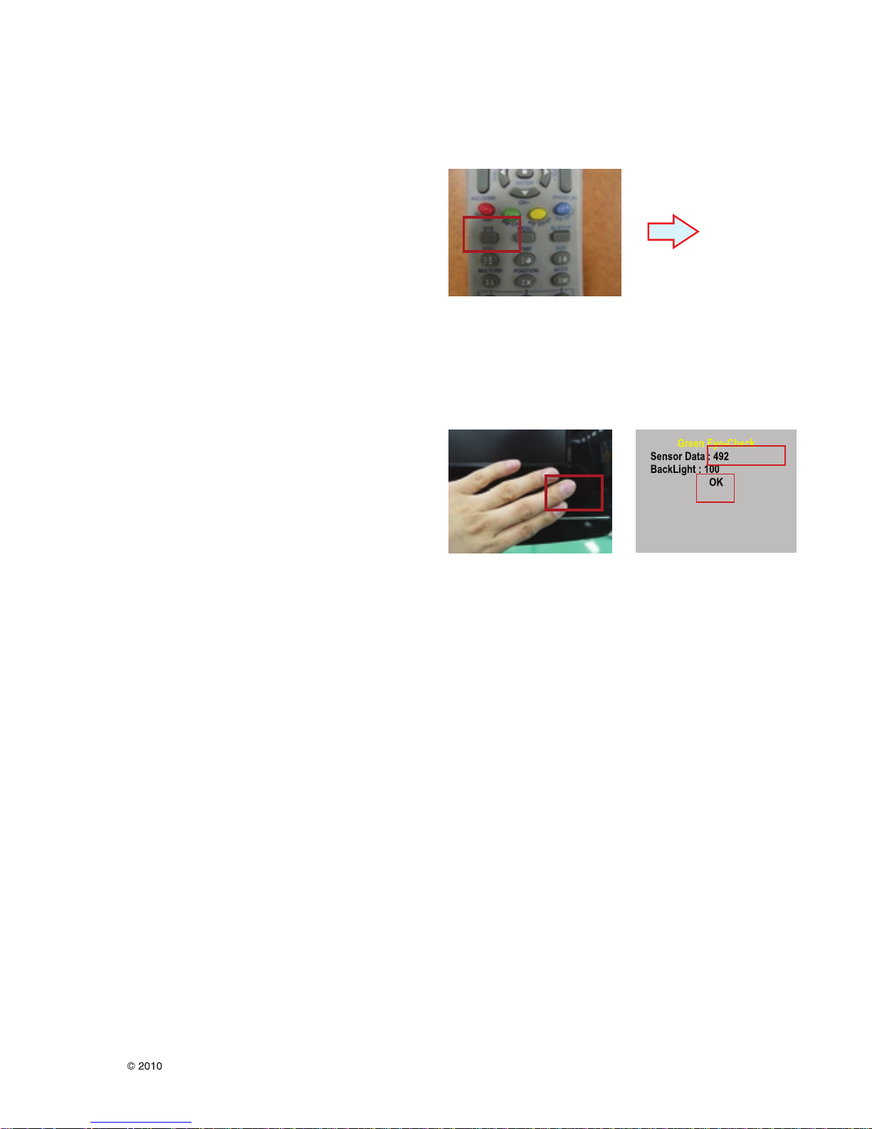
5.4. Intelligent Sensor Inspection Guide
Step 1. Turn on the TV set.
Step 2. Press “EYE” button on the Adjustment remote
controller.
Step 3. Block the Intelligent Sensor module on the front C/A
about 6 seconds.
When the “Sensor Data” is lower than 20, you can see the
“OK” message
=> If it doesn’t show “OK” message, the Sensor Module is
defected one.
You have to replace that with a good one.
Step 4. After check the “OK” message come out, take out your
hand from the Sensor module.
=> Check “Sensor Data” value change from “0” to “300” or not.
If it doesn’t change the value, the sensor is also defected one.
You have to replace it.

- 13 -
LGE Internal Use OnlyCopyright LG Electronics. Inc. All right reserved.
Only for training and service purposes
5.5. Blue-Tooth Inspection Guide
5.5.1. Test Condition.
Must located another set in a state of DC ON (without
checking set) in closer distance(5M).
-On total assembly step, S/W deal with connection
(between Set and another Set, other device that be
compatible with Bluetooth)
5.5.2. Need device : same set in closer distance,
adjustment remote control
5.5.3. Method
1) Push “Power on key” on adjustment remote control.
change “Bluetooth On” mode
2) Push “EXIT” KEY
3) Push ”B-TOOTH”(NEW) or “PIP”(OLD) Key
4) Check “Searching OK” message
5) Push “Exit” key, finish check.
5.6. Local Dimming Inspection (Optional)
5.6.1. Edge LED models with local dimming
1) Press ‘TILT” key of the Adj. R/C and check moving patterns.
The black bar patterns moves from left to right. If local
dimming function does not work, a whole screen shows full
white.
5.6.2. IOP LED models with local dimming
1) Press ‘TILT” key of the Adj. R/C and check moving patterns.
The black cross-bar patterns moves from top-left to Bottomright. If local dimming function does not work, a whole
screen shows full white.
5.7. Preset CH information
5.7.1. Analog CH Table_Ver_1_0
Storage Factory System Band CH CH Name Freq(Mhz) Freq/50Khz
0
1 PAL BG V/UHF NZ01 C 01 45.25 905
2 SECAM DK V/UHF R34 C 34 575.25 11 505
3 PAL BG V/UHF EU05 C 05 175.25 3505
4 PAL I Cable PI11 S 11 231.25 4625
5 NTSC V/UHF BR48 675.25
6 PAL BG V/UHF E04 C 04 62.25 1245
7 PAL BG V/UHF EU07 C 07 189.25 3785
8 PAL BG V/UHF EU50 C 50 703.25 14065
Initial CH
(Gumi)
9 PAL BG V/UHF EU52 C 52 719.25 14385
10 PAL I V/UHF PI41 C 41 631.25 12625
11 PAL I V/UHF PI63 C 63 807.25 16145
12 PAL BG Cable 5 S 47 102.25 2045
13 PAL BG V/UHF 21 C 21 471.25 9425
14 SECAM L V/UHF SLB C 02 55.75 1115
15 SECAM L Cable CATVE S 07 152.75 3055
16
17
18 PAL B V/UHF E5 C 05 175.25 3505
19 PAL G V/UHF E51 C 51 711.25 14225
20 PAL I V/UHF I41 C 41 631.25 12625
21 SECAM D V/UHF R5 C 05 93.25 1865
22
23 PAL G V/UHF E31 C 31 551.25 11025
24 PAL I V/UHF I21 C 21 471.25 9425
25 PAL I V/UHF I69 C 69 855.25 17105
26 PAL G V/UHF E48 C 48 687.25 13745
27 SECAM L V/UHF L4 C 08 200.00 4000
28 SECAM L V/UHF L45 C 45 663.25 13265
29 PAL G V/UHF E25 C 25 503.25 10065
30 SECAM D V/UHF R7 C 07 183.25 3665
31
32
33
34 NTSC M V/UHF US-4 C 04 67.25 1345
35 NTSC M V/UHF J-01 C 01 91.25 1825
36 NTSC M V/UHF US-13(J-11) C 13 211.25 4225
37 NTSC M V/UHF US-14(J-13) C 14 471.25 9425
38 NTSC M V/UHF US-63(J62) C 63 765.25 15305
39 NTSC M Cable CATV -15 S 15 127.25 2545
40 NTSC M V/UHF US-18(Digital) C 18 497(Center Freq)
41 SECAM D/K V/UHF R-1(CIS) C 01 49.75 995
42 PAL D/K V/UHF D-10(China10) C 10 200.25 4005
43 PAL D/K V/UHF K-36 C 36 695.25 13905
44 PAL B/G V/UHF E-5 C 05 175.25 3505
45 PAL B/G V/UHF G-40 C 40 623.25 12465
46
47
48
49 PAL D/K V/UHF D-1 C 01 49.75 995
50 PAL D/K V/UHF D-4 C 04 77.25 1545
51 PAL D/K V/UHF D-10 C 10 200.25 4005
52 PAL B/G V/UHF E-5 C 05 175.25 3505
53 SECAM D/K V/UHF R-12 C 12 223.25 4465
54 NTSC M V/UHF US-14 C 14 471.25 9425
55 SECAM D/K V/UHF R-34 C 34 575.25 11505
56 PAL I V/UHF I-41 C 41 631.25 12625
57
58
59 SECAM B/G V/UHF E-04 C 04 62.25 1245
60 SECAM D/K V/UHF R-05 C 05 93.25 1865
61 PAL B/G V/UHF E-05 C 05 175.25 3505
62 SECAM D/K V/UHF R-12 C 12 223.25 4465
63 PAL B/G V/UHF E-21 C 21 471.25 9425
64 SECAM D/K V/UHF R-34 C 34 575.25 11505
65
66
67
68 PAL B/G V/UHF E-2 C 02 48.25 965
69 PAL B/G V/UHF E-5 C 05 175.25 3505
70 PAL B/G V/UHF E-11 C 11 217.25 4345
71 PAL B/G V/UHF E-25 C 25 503.25 10065
72 PAL B/G V/UHF E-36 C 36 591.25 11825
73 PAL I V/UHF I-30 C 30 543.25 10865
74 PAL I Cable I-11 S 11 231.25 4625
75 SECAM D/K Cable R-05 S 45 93.25 1865
76 SECAM D/K V/UHF R-34 C 34 575.25 11 505
77 SECAM L V/UHF F-B C 47 55.75 1115
78 NTSC M V/UHF US-04 C 4 67.25 1345
79 PAL N V/UHF N-10 C 10 193.25 3865
80 NTSC M V/UHF US-11 C 11 199.25 3985
81 NTSC M V/UHF US-13 C 13 211.25 4225
82 NTSC M V/UHF US-30 C 30 567.25 11345
83 SECAM L V/UHF F-49 C 49 695.25 13905
84 PAL M V/UHF M-69 C 69 801.25 16025
85 JAPAN M Cable JA-01 S-95 91.25 1825
86 JAPAN M V/UHF JA-04 J 4 171.25 3425
87 JAPAN M V/UHF JA-36 37 609.3 12186
88
89
90
91 PAL B/G V/UHF E-05 C 05 175.25 3505
92 NTSC M V/UHF US-13 C 13 211.25 4225
93 SECAM D/K V/UHF R-12 C 12 223.25 4465
94 PAL D/K V/UHF D-01 C 01 49.75 995
95 SECAM D/K V/UHF R-34 C 34 575.25 11505
96 PAL B/G V/UHF E-21 C 21 471.25 9425
97
SECAM L V/UHF SL36 C 36 591.25 11825
PAL B
MA
(WR)
SECAM D V/UHF R7 C 07 189.25
NT
PAL I V/UHF I-28 C 28 527.25 10545
NT_
PANDA
NTSC M V/UHF US-63 C 63 765.25 15305
RA
SECAM D/K V/UHF R-54 C 54 735.25 14705
IN
PAL B/G Cable Au-5 S-47 102.25 2045
NP
PAL D/K V/UHF D-04 C 04 77.25 1545
V/UHF
E4
C 04
62.25
1245
- 14 -
LGE Internal Use OnlyCopyright LG Electronics. Inc. All right reserved.
Only for training and service purposes
5.7.2. Preset CH write condition
1) AC on time on only one after assembled automatically
2) In case of PAL model, CH recover on SVC OSD manually
In case of NTSC model, default channel : -> After In-Stop /
Facotry reset
TV : 2,3,4,5,6,7,8,9,10,11,12,13,14,30,51,55,63 CATV :
15,16,17,55,95
5.7.3. Preset CH erase condition
1) In-Stop key
5.8. Internal press test
5.9. Motion Remote controller Inspection
5.9.1. Equipment : Motion remote controller for
test, IR-KEY-CODE remote controller for
test Check battery before test.
(Recommend : Change battery for every
Lot.)
5.9.2. Process
1) Push “Mute” or “ START” key for pairing between TV-set
and motion remote controller.
2) Push “OK” or “Enter” key, you can see the Cursor on
screen.
3) Push “Vol+” or “STOP” key, Disconnect Pairing.
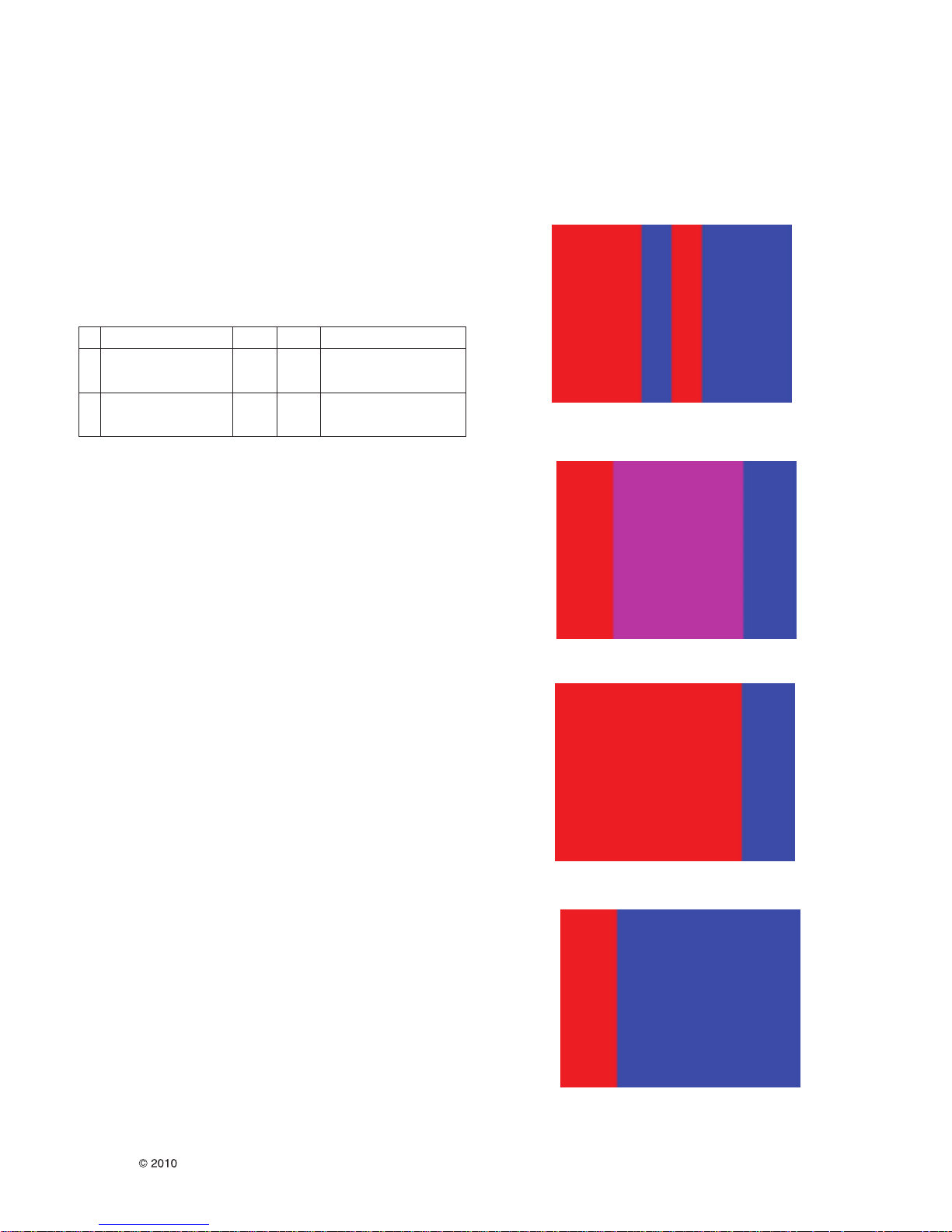
5.10. 3D Function test
5.10.1. Equipment : Pattern Generator MSPG3233, HDMI mode 37, pattern No. 81
5.9.2. Process
1) Connect HDMI (HDMI mode 371, Pattern No. 81)
2) Insert 3D Mode, Select side by side mode.
3) Without 3D-glasses, Like below figure.
4) With 3D left-glass, Like below figure. (Center is RED)
5) With 3Dright-glass, Like below figure.(Center is Blue)
No Item Vallue Unit Remark
1.
Dielectric Voltage(AC<->FG)
1.5 kV At 100mA for 1sec(Line)
1.5 At 100mA for 1min(OQC)
2.
Dielectric Voltage(Without FG)
3 kV At 100mA for 1sec(Line)
3 At 100mA for 1min(OQC)

- 15 -
LGE Internal Use OnlyCopyright LG Electronics. Inc. All right reserved.
Only for training and service purposes
** Appendix **
D. Bluetooth S/W Upgrade by using USB drive Input
1. Preparation Equipment
a. USB Memory Stick
b. New Bluetooth Software
c. Copy New File
Copy Bluetooth software MCL389x.bin file to memory stick
with out folder.
*Caution : Do no t copy the file to the inside folder
2. Connection
Plug-in USB Memory stick to the USB input of the set.
3. USB input Automatically loading menu
* The OSD “USB Device loading” is appealed by
automatically….
4. Selecting Window for Bluetooth Software update
• The Pop-up window appears for selecting to update
Bluetooth software and information about current Bluetooth
software. (Ex : V2.02)
• Select “Yes”
- 16 -
LGE Internal Use OnlyCopyright LG Electronics. Inc. All right reserved.
Only for training and service purposes
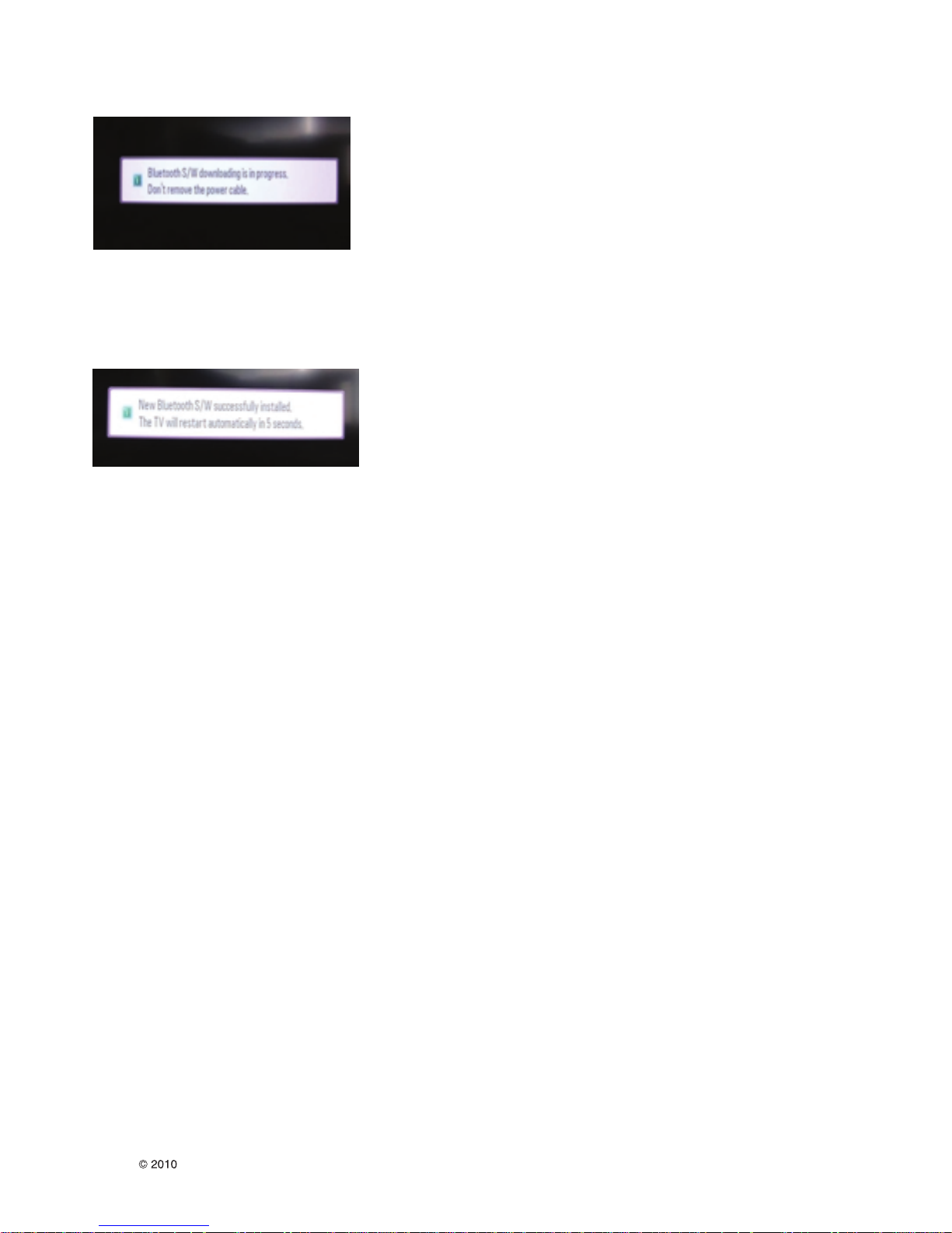
5. Bluetooth S/W Downloading Process
• Time Process Downloading new Bluetooth software about
10seconds
• Please Wait until finish and do not un-plug power cable
6. OSD – Bluetooth software updated successfully
• OSD Information Bluetooth software update success
• LCDTV Set will restart by automatically…
• Time Process to restart about 5seconds
7. Check S/W Version
• Push “ IN-START” button on service remote Controller
• Check Information Bluetooth S/W version will appear on
OSD Service Menu.
Example : Bluetooth SW version 2.05
830
400
521
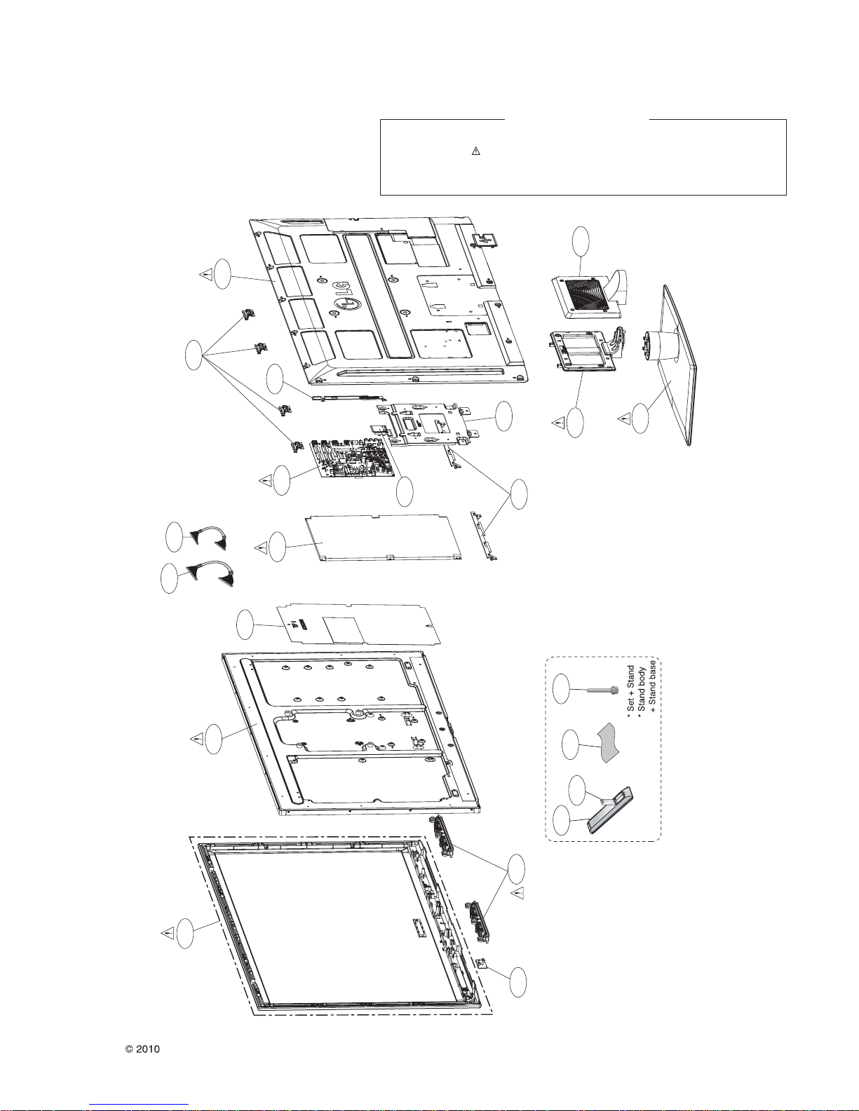
EXPLODED VIEW
IMPORTANT SAFETY NOTICE
Many electrical and mechanical parts in this chassis have special safety-related characteristics. These
parts are identified by in the Schematic Diagram and EXPLODED VIEW.
It is esse ntia l that t hese speci al safety parts shoul d be repla ced with the same compo nent s as
recommended in this manual to prevent X-RADIATION, Shock, Fire, or other Hazards.
Do not modify the original design without permission of manufacturer.
920
LV1
LV2
200
800
540
530
880
820
840
A10
A5
A2
910
A21
900
300
Only for training and service purposes
- 17 -
120
500
LGE Internal Use OnlyCopyright LG Electronics. Inc. All right reserved.
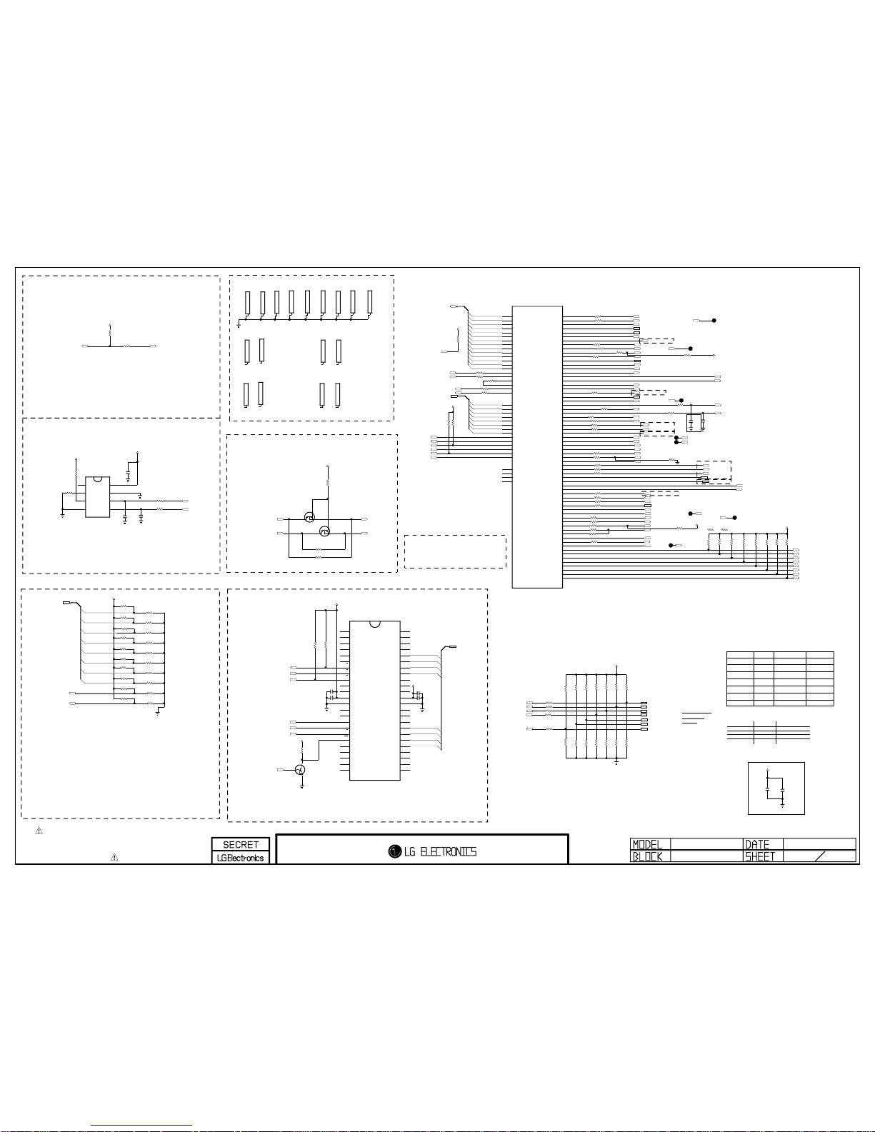
THE SYMBOL MARK OF THIS SCHEMETIC DIAGRAM INCORPORATES
SPECIAL FEATURES IMPORTANT FOR PROTECTION FROM X-RADIATION.
FILRE AND ELECTRICAL SHOCK HAZARDS, WHEN SERVICING IF IS
ESSENTIAL THAT ONLY MANUFATURES SPECFIED PARTS BE USED FOR
THE CRITICAL COMPONENTS IN THE SYMBOL MARK OF THE SCHEMETIC.
2009.06.18
BCM3556 & NAND FLASH
BCM (EUROBBTV)
NAND_DATA[7]
CI_A[0]
CI_A[3]
CI_A[2]
NAND_DATA[6]
NAND_DATA[6]
NAND_DATA[2]
CI_A[12]
NAND_DATA[0]
NAND_DATA[4]
NAND_DATA[3]
NAND_DATA[3]
NAND_DATA[1]
NAND_DATA[2]
CI_A[8]
CI_A[5]
NAND_DATA[7]
CI_A[6]
NAND_DATA[5]
NAND_DATA[7]
NAND_DATA[0]
NAND_DATA[5]
NAND_DATA[1]
NAND_DATA[0]
CI_A[9]
CI_A[11]
NAND_DATA[6]
CI_A[13]
CI_A[7]
NAND_DATA[5]
CI_A[4]
NAND_DATA[2]
NAND_DATA[4]
NAND_DATA[4]
CI_A[10]
NAND_DATA[0-7]
CI_A[1]
NAND_DATA[1]
NAND_DATA[3]
R132
22
R127
22
R117
33
R1037
2.7K
OPT
R1003
2.7K
NAND_WEb
PWM_DIM
DSUB_DET
NAND_DATA[0-7]
R1007
2.7K
OPT
R102
22
SC_RE2
NAND_CEb
R1012 100
MODEL_OPT_5
R1022 1K
DDR_512MB
MODEL_OPT_1
C115
0.1uF
R169
2.7K
C114
0.1uF
NAND_REb
R133
22
SCL3_3.3V
R1023 1K
NON_GIP
R1001
2.7K
MODEL_OPT_0
R193 4.7K
FRC_RESET
NAND_ALE
CI_OUTCLK
MODEL_OPT_1
C116
4700pF
SDA1_3.3V
MODEL_OPT_2
R140
22
A_DIM
R194 4.7K
R1008
2.7K
OPT
RGB_DDC_SCL
R1040
2.7K
OPT
NAND_ALE
R1039
2.7K
EBI_WE
/CI_IREQ
C103
0.1uF
CI_MOD_RESET
RF_SWITCH_CTL
MODEL_OPT_0
R109 100
NAND_CLE
+3.3V_NORMAL
C167
8pF
OPT
R1000
2.7K
MODEL_OPT_5
NAND_CEb
TUNER_RESET
R122
22
ERROR_OUT
R1024 100
NAND_CLE
NAND_REb
R130
22
NAND_WEb
+3.3V_NORMAL
R1002
2.7K
OPT
AV_CVBS_DET
+3.3V_NORMAL
R1033
22
R157
2.7K
OPT
CI_A[0-13]
SIDE_AV_DET
IF_AGC_SEL
EPHY_LINK
MODEL_OPT_4
R1045
4.7K
NAND_RBb
R1006
2.7K
OPT
R136
4.7K
R1018 1K
NO_FRC
R1005
2.7K
R1011 1K
MINI_LVDS/NO LOCAL_D
FE_TS_VAL_ERR
+3.3V_NORMAL
SDA3_3.3V
R1019 100
/CI_CD2
R1013 1K
EXTERNEL FRC/T_CON FRC
+3.3V_NORMAL
R1015 1K
DDR_256MB
BT_RESET
R156
2.7K
+3.3V_NORMAL
NAND_DATA[0-7]
R108
100
R158
2.7K
OPT
NAND_CLE
R1021 1K
HD
R110 100
SC_RE1
MODEL_OPT_2
R111
22
R1034
2.7K
+3.3V_NORMAL
R1004
2.7K
OPT
SCL1_3.3V
C171
8pF
OPT
IC102
M24M01-HRMN6TP
3
E2
2
E1
4
VSS
1
NC
5
SDA
6
SCL
7
WP
8
VCC
MODEL_OPT_3
CI_5V_CTL
R134 2.7K
R191 2.7K
SCL0_3.3V
R1020 1K
FRC
+3.3V_NORMAL
EBI_CS
R1009 1K
GIP
RGB_DDC_SDA
+3.3V_NORMAL
EBI_CS
R1046
22
/CI_WAIT
NAND_DATA[0-7]
EBI_RW
R1035
2.7K
R1044
0
BCM_RX
EPHY_ACTIVITY
Q101
KRC103S
E
B
C
R1017 1K
FHD
R1038
2.7K
R129
22
MODEL_OPT_4
R1014 1K
LVDS/LOCAL_D
HP_DET
NAND_ALE
SDA0_3.3V
BCM_TX
FLASH_WP
LNA2_CTL/BOSTER_CTL
R1036
2.7K
OPT
+3.3V_NORMAL
MODEL_OPT_3
R1010 1K
NO FRC/INTERNER FRC
R107
100
/CI_CD1
R116
22
NAND_RBb
R1027
10K
SYS_RESETb
+3.3V_NORMAL
SOC_RESET
WIRELESS_DL_TX
WIRELESS_DL_RX
COMP2_DET
SDA2_3.3V
SCL2_3.3V
AUD_MASTER_CLK
SCART1_DET
VREG_CTRL
/RST_HUB
R1030 0
R1032
0
R1025
4.7K
C136 10uF
10V
SDA3_3.3V
SCL3_3.3V
R1026 22
R1028 22
DTV_ATV_SELECT
SIDE_COMP_DET
POWER_DET
R1047
0
OPT
HDMI_HPD_4
HDMI_HPD_3
HDMI_HPD_2
HDMI_HPD_1
R1141K
R1029
1K
R199
1K
R106
1K
5V_HDMI_1
5V_HDMI_2
5V_HDMI_3
5V_HDMI_4
R1048
100
R1050
100
R161 100
R1049
22
R1051
22
LOCAL DIMMING
R170
1.2K
R187
1.2K
EU
R180
1.2K
R183
1.2K
R176
1.2K
R184
1.2K
EU
R171
1.2K
R177
1.2K
R123 0
WIRELESS
R124
0
WIRELESS
IC101
NAND04GW3B2DN6E
NAND FLASH
26
NC_17
27
NC_18
28
NC_19
29
I/O0
30
I/O1
31
I/O2
32
I/O3
33
NC_20
34
NC_21
35
NC_22
36
VSS_2
37
VDD_2
38
NC_23
39
NC_24
40
NC_25
41
I/O4
42
I/O5
43
I/O6
44
I/O7
45
NC_26
46
NC_27
47
NC_28
48
NC_29
17
AL
3
NC_3
6
NC_6
16
CL
15
NC_10
14
NC_9
13
VSS_1
12
VDD_1
11
NC_8
10
NC_7
9
E
8
R
7
RB
4
NC_4
5
NC_5
25
NC_16
24
NC_15
23
NC_14
2
NC_2
22
NC_13
21
NC_12
1
NC_1
20
NC_11
19
WP
18
W
SIDE_COMP_DET
Q103
FDV301N
OPT
G
D
S
Q104
FDV301N
OPT
G
D
S
R173
10K
OPT
WIRELESS_SCL
SDA2_3.3V
WIRELESS_SDA
SCL2_3.3V
+3.3V_NORMAL
R160100
LG5111_RESET
R1920
DC DC
DEMOD_RESET
DEMOD_RESET
DD
DD
M_REMOTE_RX
M_REMOTE_RX
M_REMOTE_TX
M_REMOTE_TX
R103 0
RF_SWITCH_CTL_CHB RF_SWITCH_CTL_CHB
R113
22
DEMOD_RESET
LG5111_RESET
+12V
C178
0.1uF
50V
C179
0.1uF
50V
R104112K
C173
22uF
16V
C180
100pF
50V
EMI
R105 56
R115 1.8K
R1052
4.7K
+3.3V_NORMAL
MODEL_OPT_6
/CI_SEL
MODEL_OPT_6
R118 1K
OLED
R119 1K
NON_OLED
MDS62110204
GAS6-*1
5.5T_GAS
MDS62110204
GAS7-*1
5.5T_GAS
MDS62110204
GAS1-*1
5.5T_GAS
MDS62110206
GAS6
6.5T_GAS
MDS62110206
GAS2
6.5T_GAS
MDS62110206
GAS7
6.5T_GAS
MDS62110206
GAS5
OPT
MDS62110206
GAS1
6.5T_GAS
MDS62110206
GAS4
OPT
MDS62110206
GAS3
OPT
MDS62110206
GAS8
OPT
MDS62110206
GAS9
OPT
IC100
LGE3556C (C0 VERSION)
GPIO_00
N26
GPIO_01
L26
GPIO_02
N25
GPIO_03
L25
GPIO_04
K27
GPIO_05
K28
GPIO_06
K24
GPIO_07
K26
GPIO_08
K25
GPIO_09
AA27
GPIO_10
AA28
GPIO_11
AA26
GPIO_12
L1
GPIO_13
L3
GPIO_14
L2
GPIO_15
Y25
GPIO_16
Y26
GPIO_17
M27
GPIO_18
AA25
GPIO_19
R25
GPIO_20
N28
GPIO_21
N27
GPIO_22
AH18
GPIO_23
P23
GPIO_24
M23
GPIO_25
AD19
GPIO_26
AE19
GPIO_27
M4
GPIO_28
M5
GPIO_29
L23
GPIO_30
Y28
GPIO_31
Y27
GPIO_32
G2
GPIO_33
G3
GPIO_34
G5
GPIO_35
G6
GPIO_36
G4
GPIO_37
L24
GPIO_38
P25
GPIO_39
L5
GPIO_40
K4
GPIO_41
K1
GPIO_42
L27
GPIO_43
M26
GPIO_44
N23
GPIO_45
R28
GPIO_46
R27
GPIO_47
R26
GPIO_48
P28
GPIO_49
P27
GPIO_50
K6
GPIO_51
K5
GPIO_52
P26
GPIO_53
M3
GPIO_54
M2
GPIO_55
M1
GPIO_56
L4
GPIO_57
L6
SGPIO_00
W27
SGPIO_01
W28
SGPIO_02
W26
SGPIO_03
W25
SGPIO_04
J2
SGPIO_05
J1
SGPIO_06
K3
SGPIO_07
K2
EBI_ADDR3
J23
EBI_ADDR4
J24
EBI_ADDR2
H25
EBI_ADDR1
H24
EBI_ADDR0
H23
EBI_ADDR5
J25
EBI_ADDR6
F26
EBI_ADDR8
H28
EBI_ADDR9
J26
EBI_ADDR13
H27
EBI_ADDR12
G26
EBI_ADDR11
J27
EBI_ADDR10
J28
EBI_ADDR7
F27
EBI_TAB
G24
EBI_WE1B
H26
EBI_CLK_IN
G27
EBI_CLK_OUT
G28
EBI_RWB
K23
EBI_CS0B
G25
NAND_DATA0
U24
NAND_DATA1
T26
NAND_DATA2
T27
NAND_DATA3
U26
NAND_DATA4
U27
NAND_DATA5
V26
NAND_DATA6
V27
NAND_DATA7
V28
NAND_CS0B
T24
NAND_ALE
R23
NAND_REB
T23
NAND_CLE
T25
NAND_WEB
R24
NAND_RBB
U25
SF_MISO
W24
SF_MOSI
U23
SF_SCK
V23
SF_CSB
V24
MDS62110205
GAS6-*2
7.5T_GAS
MDS62110205
GAS1-*2
7.5T_GAS
MDS62110205
GAS7-*2
7.5T_GAS
BT_ON/OFF
R181 100
BCM BT MODULE
MDS62110204
GAS2-*1
5.5T_GAS
MDS62110205
GAS2-*2
7.5T_GAS
+3.3V_NORMALR1053 2.7K
R1042 22
R184-*1
2.2K
NON_EU
R187-*1
2.2K
NON_EU
1
Default Res. of all NAND pin is Pull-down
For CI
For CI
* I2C MAP
* NAND FLASH MEMORY 4Gbit (512M for BB)
MODEL OPTION
External Demod.
Open Drain
* I2C_0 :
* I2C_1 :
* I2C_2 :
* I2C_3 :
BB Add.
For CI
Boot Strap
RESET
A8’h
NAND_IO[0] : Flash Select (1)
0 : Boot From Serial Flash
1 : Boot From NAND Flash
NAND_IO[1] : NAND Block 0 Write (DNS)
0 : Enable Block 0 Write
1 : Disable Block 0 Write
NAND_IO[3:2] : NAND ECC (1, DNS)
00 : No ECC
01 : 1 ECC Bit
10 : 4 ECC Bit
11 : 8 ECC Bit
NAND_IO[4] : CPU Endian (0)
0 : Little Endian
1 : Big Endian
NAND_IO[6:5] : Xtal Bias Control (1, DNS)
00 : 1.2mA (Fundmental Recommand)
01 : 1.8mA
10 : 2.4mA (3rd over tune Recommand)
11 : 3.0mA
NAND_IO[7] : MIPS Frequency (DNS)
0 : 405MHz
1 : 378MHz
NAND_ALE : I2C Level (DNS)
0 : 3.3V Switching
1 : 5V Switching
NAND_CLE
0 : Enable D2CDIFF AC (DNS)
1 : Disabe D2CDIFF AC
NVRAM
EXT IRQ
GPIO_00, GPIO_01, GPIO_02,
GPIO_11, GPIO_11, GPIO_39
IR_INT : GPIO_23
IR1_IN : GPIO_25
IR2_IN : GPIO_29
IR_OUT : GPIO_26
PWM0 : GPIO_24
PWM1 : GPIO_09
IR_IN
INTERRUPT PIN
INTERRUPT PIN
INTERRUPT PIN
IR_IN
BCM_AVC_DEBUG_TX1
BCM_AVC_DEBUG_RX1
BT_MUTE
From wireless_I2C to micom I2C
SMD GASKET
15page:TW_9910_RESET
17page:M_RFMODULE_RESET
15page:CHB_RESET
17page : Motion Remocon
17page : Motion Remocon
28page : ISDB Demod
17page : Motion Remocon
17page : Motion Remocon
15page : CHB_SUB_TUNER
FOR ESD 12V Pattern
URSA3 External
HIGH
LOW
HIGH
OLED
LOW
DDR-256M
MODEL_OPT_4
HIGH
MAIN_MINI_LVDSHDMAIN_LVDS
K1
NON_OLED
MODEL_OPT_3
MODEL_OPT_6
MODEL_OPT_4
L25
N28
MODEL_OPT_5
FRC
MODEL_OPT_0
MODEL_OPT_2
DDR-512M
HIGH
GIP
PIN NAME
PWIZ Pannel T-con
with LG FRC
MODEL_OPT_1 AA26
HIGH
R26
URSA3 Internal
LOW
NON_URSA3
LOW
K4
*MODEL_OPT_0 & MODEL_OPT_4
REFER TO THIS OPTION
NON-GIP
PIN NO.
LOW
K27
NO FRC
NON_FRC
MODEL_OPT_0
FHD
URSA3
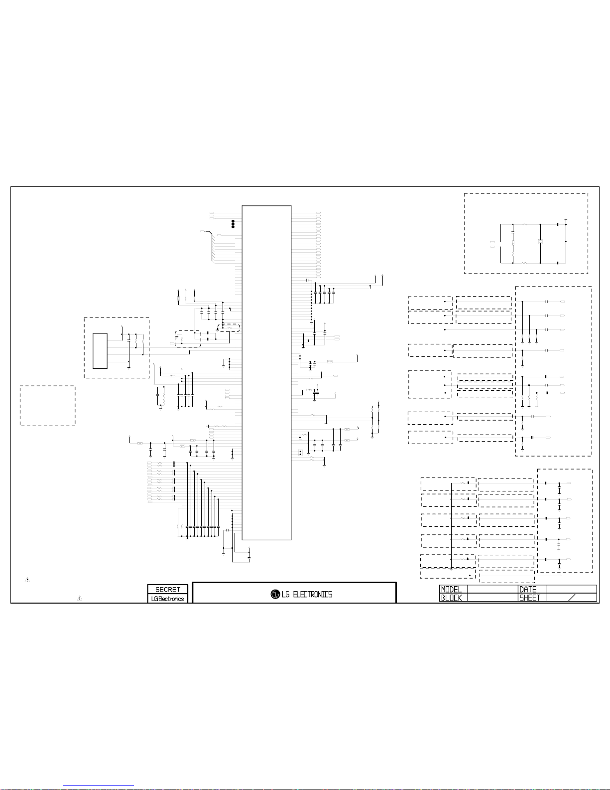
THE SYMBOL MARK OF THIS SCHEMETIC DIAGRAM INCORPORATES
SPECIAL FEATURES IMPORTANT FOR PROTECTION FROM X-RADIATION.
FILRE AND ELECTRICAL SHOCK HAZARDS, WHEN SERVICING IF IS
ESSENTIAL THAT ONLY MANUFATURES SPECFIED PARTS BE USED FOR
THE CRITICAL COMPONENTS IN THE SYMBOL MARK OF THE SCHEMETIC.
BCM3556 AUD_IN/LVDS
2009.06.18
BCM (EUROBBTV)
CI_OUTDATA[6]
CI_OUTDATA[7]
CI_OUTVALID
CI_OUTSTART
CI_OUTDATA[1]
CI_OUTDATA[2]
CI_OUTDATA[0]
CI_OUTDATA[3]
CI_OUTDATA[4]
CI_OUTDATA[5]
54MHz_XTAL_N
54MHz_XTAL_P
L202
BLM18PG121SN1D
C213
0.01uF
A3.3V
A2.5V
C219
0.1uF
C214
0.1uF
R220 560
A1.2V
C215
0.1uF
C223
0.1uF
+3.3V_NORMAL
R201
1.5K
R200
1.5K
L200
BLM18PG121SN1D
A2.5V
C209 0.1uF
R209
3.9K
C201
100pF
R210
120
A1.2V
C207 0.1uF
C203 0.1u F
C202 0.1u F
A3.3V
R218
240
R219
1K
C222
0.1uF
A2.5V
C295
0.1uF
A2.5V
A1.2V
C236
0.1uF
C239
0.1uF
A1.2V
C2012
0.1uF
54MHz_XTAL_P
002:I2
C251
0.1uF
54MHz_XTAL_N
002:I1
A2.5V
A1.2V
L203
BLM18PG121SN1D
C233
0.1uF
+3.3V_NORMAL
A2.5V
+3.3V_NORMAL
C234
0.1uF
SYS_RESETb
001:A6;001:B7
L204
BLM18PG121SN1D
A1.2V
A1.2V
L207
BLM18PG121SN1D
C237
0.1uF
R2221K
R2621K
R221
4.7K
L211
BLM18PG121SN1D
LVDS_TX_0_DATA3_P
013:F7;035:AK14
LVDS_TX_0_DATA0_P
013:E7;035:AK11
LVDS_TX_1_DATA3_N
013:E7;035:AK19
LVDS_TX_1_DATA1_P
013:E7;035:AK16
LVDS_TX_0_DATA1_N
013:E7;035:AK12
LVDS_TX_0_DATA1_P
013:E7;035:AK11
LVDS_TX_1_CLK_P
013:E7;035:AK18
LVDS_TX_0_DATA2_N
013:F7;035:AK12
LVDS_TX_1_CLK_N
013:E7;035:AK18
LVDS_TX_0_DATA4_P
013:F7;035:AK14
LVDS_TX_1_DATA4_P
013:E7;035:AK19
LVDS_TX_0_DATA2_P
013:F7;035:AK12
LVDS_TX_1_DATA3_P
013:E7;035:AK19
LVDS_TX_0_CLK_N
013:E7;035:AK13
LVDS_TX_0_DATA4_N
013:F7;035:AK15
LVDS_TX_0_CLK_P
013:E7;035:AK13
LVDS_TX_1_DATA4_N
013:E7;035:AK20
LVDS_TX_1_DATA1_N
013:E7;035:AK17
LVDS_TX_0_DATA3_N
013:F7;035:AK14
LVDS_TX_1_DATA0_N
013:E7;035:AK16
LVDS_TX_1_DATA0_P
013:E7;035:AK16
LVDS_TX_1_DATA2_P
013:E7;035:AK17
LVDS_TX_1_DATA2_N
013:E7;035:AK17
LVDS_TX_0_DATA0_N
013:E7;035:AK11
SC1_LR_INCM
002:J7
REAR_AV_LR_INCM
002:J6
R233 51
R231 51
R230 51
R234 51
R229 51
R232 51
COMP2_LR_INCM
002:J6
SC1_L_IN
041:B5
R228 51
PC_LR_INCM
002:J7
PC_R_IN
009:I3
SC1_R_IN
041:B5
PC_L_IN
009:I3
R215 51
C238
0.1uF
D3.3V
R235
2.7K
P200
TJC2508-4A
1
2
3
4
A1.2V
R240
390
OPT
R243
604
L208
1008LS-272XJLC
C257
33pF
R212
22
R211
22
C229
12pF
C230
12pF
X903
54MHz
21
3
R245
34
R251
34
COMP2_VID_INCM
TU_CVBS_INCM
003:A3
R257
5.1
R256
5.1
B_VID_INCM
003:A5
R258
5.1
R259
5.1
R252
5.1
C2016 0.1uF
C2015 0.1uF
C258 0.1uF
R250
34
C262 0.1uF
R_VID_INCM
003:A5
R24834R244
34
REAR_AV_LR_INCM
002:C6
C264 0.1uF
R24634R247
34
C261 0.1uF
SIDE_AV_LR_INCM
002:C6
C2019 0.1uF
COMP2_LR_INCM
002:C6
G_VID_INCM
003:A5
PC_LR_INCM
002:C6
REAR_AV_CVBS_INCM
003:A3
C2014
0.15uF
C2024
0.15uF
C265
0.15uF
C2022
0.15uF
C269
0.15uF
EPHY_TDN
EPHY_TDP
A2.5V A1.2V
EPHY_RDP
C244
0.1uF
16V
L210
BLM18PG121SN1D
C247
0.1uF
C2020
0.1uF
EPHY_RDN
L209
BLM18PG121SN1D
L212
BLM18PG121SN1D
CI_OUTDATA[0-7],CI_OUTSTART,CI_OUTVALID
045:V14
CI_A[14]
SC1_CVBS_INCM
003:A3
C2011 0.1uF
R260
34
SIDE_AV_CVBS_INCM
003:A3
R261
34
C2023 0.1uF
FE_TS_DATA_CLK
FE_TS_SERIAL
FE_TS_SYNC
TU_SIF_INCM
003:A3
SC1_LR_INCM
002:C6
SC1_RGB_INCM
003:A4
R249
1K
R204 51
R214 51
BT_DP
BT_DM
SIDE_USB_DM
SIDE_USB_DP
COMP2_L_IN
COMP2_R_IN
DTV/MNT_V_OUT
REAR_AV_R_IN
041:B5
REAR_AV_L_IN
041:B5
SIDE_AV_LR_INCM
002:J6
SIDE_AV_L_IN
041:B5
SIDE_AV_R_IN
041:B5
C212
4.7uF
C2028
4.7uF
C208 4.7uF
C2026
4.7uF
C2021
4.7uF
C2018
4.7uF
C217
10uF
C228
10uF
OPT
C242
4.7uF
C2013
4.7uF
C235
4.7uF
C241
4.7uF
C240
4.7uF
C231
10uF
C270
0.47uF
C271
0.47uF
C2025
0.47uF
C2010
0.47uF
C2017
0.47uF
TP4021
TP4022
TP4023
R2360R237
0
R224
2.7K
OPT
R225
2.7K
OPT
R227
2.7K
R226
2.7K
C224 0.015uF
C226 0.015uF
C210 0.015uF
C206 0.015uF
C232 0.015uF
C220 0.015uF
C225 0.015uF
C221 0.015uF
C211 0.015uF
C227 0.015uF
C298 0.047uF
C279 0.047uF
C277
0.047uF
C253 0.047uF
C256 0.047uF
C254 0.047uF
C2027 0.047uF
C296 0.047uF
C299 0.047uF
C252 0.047uF
R264 0
R265
0
R266
2.7K
R238
75
1%
IC100
LGE3556C (C0 VERSION)
PKT0_CLK
D23
PKT0_DATA
C24
PKT0_SYNC
B26
RMX0_CLK
A25
RMX0_DATA
B25
RMX0_SYNC
A26
POD2CHIP_MCLKI
G23
POD2CHIP_MDI0
D25
POD2CHIP_MDI1
D24
POD2CHIP_MDI2
C25
POD2CHIP_MDI3
E27
POD2CHIP_MDI4
E26
POD2CHIP_MDI5
D28
POD2CHIP_MDI6
D27
POD2CHIP_MDI7
D26
POD2CHIP_MISTRT
E23
POD2CHIP_MIVAL
E24
CHIP2POD_MCLKO
F25
CHIP2POD_MDO0
C27
CHIP2POD_MDO1
C26
CHIP2POD_MDO2
B28
CHIP2POD_MDO3
B27
CHIP2POD_MDO4
A27
CHIP2POD_MDO5
F24
CHIP2POD_MDO6
F23
CHIP2POD_MDO7
E25
CHIP2POD_MOSTRT
C28
CHIP2POD_MOVAL
A28
VDAC_AVDD2P5
AC18
VDAC_AVDD1P2
AF20
VDAC_AVDD3P3_1
AG20
VDAC_AVDD3P3_2
AG21
VDAC_AVSS_1
AF19
VDAC_AVSS_2
AD20
VDAC_AVSS_3
AE20
VDAC_RBIAS
AH22
VDAC_1
AH20
VDAC_2
AG19
VDAC_VREG
AH21
BSC_S_SCL
M25
BSC_S_SDA
M24
USB_AVSS_1
R6
USB_AVSS_2
T6
USB_AVSS_3
R7
USB_AVSS_4
T7
USB_AVSS_5
T8
USB_AVDD1P2
R3
USB_AVDD1P2PLL
U3
USB_AVDD2P5
T4
USB_AVDD2P5REF
T3
USB_AVDD3P3
R4
USB_RREF
U4
USB_DM1
V1
USB_DP1
V2
USB_DM2
U1
USB_DP2
U2
USB_MONCDR
T5
USB_MONPLL
R5
USB_PWRFLT_1
R1
USB_PWRFLT_2
R2
USB_PWRON_1
T2
USB_PWRON_2
T1
EPHY_VREF
P6
EPHY_RDAC
P5
EPHY_RDN
P3
EPHY_RDP
P2
EPHY_TDN
N3
EPHY_TDP
N2
EPHY_AVDD1P2
P1
EPHY_AVDD2P5
P4
EPHY_PLL_VDD1P2
N4
EPHY_AGND_1
N1
EPHY_AGND_2
N5
EPHY_AGND_3
P7
AUDMX_LEFT1
AE6
AUDMX_RIGHT1
AD7
AUDMX_INCM1
AF6
AUDMX_LEFT2
AH4
AUDMX_RIGHT2
AG5
AUDMX_INCM2
AG4
AUDMX_LEFT3
AG6
AUDMX_RIGHT3
AF7
AUDMX_INCM3
AE7
AUDMX_LEFT4
AH5
AUDMX_RIGHT4
AG7
AUDMX_INCM4
AH6
AUDMX_LEFT5
AD8
AUDMX_RIGHT5
AF8
AUDMX_INCM5
AE8
AUDMX_LEFT6
AH7
AUDMX_RIGHT6
AH8
AUDMX_INCM6
AG8
AUDMX_AVSS_1
AF5
AUDMX_AVSS_2
AB9
AUDMX_AVSS_3
AA10
AUDMX_AVSS_4
AB10
AUDMX_AVSS_5
AA11
AUDMX_AVSS_6
AB11
AUDMX_LDO_CAP
AC8
AUDMX_AVDD2P5
AE5
LVDS_TX_0_DATA0_P
B4
LVDS_TX_0_DATA0_N
A4
LVDS_TX_0_DATA1_P
C6
LVDS_TX_0_DATA1_N
B6
LVDS_TX_0_DATA2_P
B3
LVDS_TX_0_DATA2_N
A3
LVDS_TX_0_DATA3_P
A1
LVDS_TX_0_DATA3_N
A2
LVDS_TX_0_DATA4_P
D5
LVDS_TX_0_DATA4_N
D6
LVDS_TX_0_CLK_P
C5
LVDS_TX_0_CLK_N
B5
LVDS_TX_1_DATA0_P
B1
LVDS_TX_1_DATA0_N
B2
LVDS_TX_1_DATA1_P
C2
LVDS_TX_1_DATA1_N
C3
LVDS_TX_1_DATA2_P
D1
LVDS_TX_1_DATA2_N
D2
LVDS_TX_1_DATA3_P
E1
LVDS_TX_1_DATA3_N
E2
LVDS_TX_1_DATA4_P
E3
LVDS_TX_1_DATA4_N
E4
LVDS_TX_1_CLK_P
D3
LVDS_TX_1_CLK_N
D4
LVDS_PLL_VREG
F5
LVDS_TX_AVDDC1P2
F1
LVDS_TX_AVDD2P5_1
F4
LVDS_TX_AVDD2P5_2
F2
LVDS_TX_AVSS_1
C1
LVDS_TX_AVSS_2
F3
LVDS_TX_AVSS_3
C4
LVDS_TX_AVSS_4
A5
LVDS_TX_AVSS_5
E5
LVDS_TX_AVSS_6
E6
LVDS_TX_AVSS_7
D7
LVDS_TX_AVSS_8
E7
LVDS_TX_AVSS_9
F7
LVDS_TX_AVSS_10
G7
LVDS_TX_AVSS_11
H7
CLK54_AVDD1P2
AD27
CLK54_AVDD2P5
AD28
CLK54_AVSS
AD26
CLK54_XTAL_N
AC26
CLK54_XTAL_P
AC27
CLK54_MONITOR
AE25
PM_OVERRIDE
Y23
VCXO_AGND_1
AA23
VCXO_AGND_2
AB24
VCXO_AGND_3
AC24
VCXO_AVDD1P2
AF25
VCXO_PLL_AUDIO_TESTOUT
AF24
RESET_OUTB
P24
RESETB
F6
NMIB
N24
TMODE_0
J5
TMODE_1
J4
TMODE_2
J6
TMODE_3
J3
SPI_S_MISO
V25
POR_OTP_VDD2P5
AH3
POR_VDD1P2
AB8
EJTAG_TCK
H4
EJTAG_TDI
H3
EJTAG_TDO
H2
EJTAG_TMS
H1
EJTAG_TRSTB
G1
EJTAG_CE0
H6
EJTAG_CE1
H5
PLL_MAIN_AVDD1P2
AB26
PLL_MAIN_AGND
AC25
PLL_MAIN_MIPS_EREF_TESTOUT
AB27
PLL_RAP_AVD_TESTOUT
M6
PLL_RAP_AVD_AVDD1P2
N6
PLL_RAP_AVD_AGND
N7
BYP_CPU_CLK
AA24
BYP_DS_CLK
Y24
BYP_SYS216_CLK
AE24
BYP_SYS175_CLK
AD25
2
Route INCM between associated
left and right signals of same channel
The INCM trace ends at the
same point where the connector
ground connects to the board ground
(thru-hole connector pin).
Place test points, resistors
near audio connector.
Connect the other side of
the resistor to GND as close
as possible to the ground
connection of the associated
audio connector.
54MHz X-TAL
R220 : BCM recommened resistor 562 ohm
BROAD BAND STUDIO
When usding FUNDMENTAl then series R = 0 ohm and CL = 8 pF
When usding Dip-type X-tal then series R = 22 ohm and CL = 12 pF
VIDEO INCM
PLACE NEAR BCM CHIP
AUDIO INCM
PLACE NEAR BCM CHIP
PLACE NEAR Jacks
Route Between SC2_L_IN & SC2_R_IN
Route Between AV1_L_IN & AV1_R_IN
Route Between COMP1_L_IN & COMP1_R_IN
Route Between SC1_L_IN & SC1_R_IN
Route Between PC_L_IN & PC_R_IN
Near J1501
Near J1600
Near J1603
Near J1500
Near J1602
Near Q1705
Near J1500
Near J1603
Near P1600
Near Q1704
Near J1501
Near J1500
Route Along With TUNER_SIF_IF_N
Run Along TUNER_CVBS_IF_P Trace
Run Along SC1_R,SC_G,SC_B Trace
Run Along COMP_Y_IN,COMP_Pr_IN,COMP_Pb_IN Trace
Run Along DSUB_R Trace
Run Along DSUB_G Trace
Run Along DSUB_B Trace
Run Along SC1_CVBS_IN Trace
Run Along SC2_CVBS_IN Trace
TP is Necessory
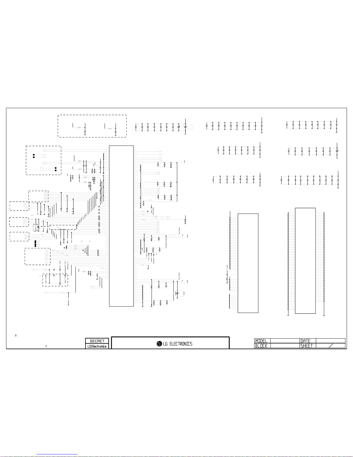
THE SYMBOL MARK OF THIS SCHEMETIC DIAGRAM INCORPORATES
SPECIAL FEATURES IMPORTANT FOR PROTECTION FROM X-RADIATION.
FILRE AND ELECTRICAL SHOCK HAZARDS, WHEN SERVICING IF IS
ESSENTIAL THAT ONLY MANUFATURES SPECFIED PARTS BE USED FOR
THE CRITICAL COMPONENTS IN THE SYMBOL MARK OF THE SCHEMETIC.
2009.06.18
BCM3556 VIDEO IN
EUROBBTV
B_VID_INCM
A2.5V
L105
BLM18PG121SN1D
A2.5V
A3.3V
R128
0
C125
0.1uF
C133
0.1uF
L103
BLM18PG121SN1D
A1.2V
L107
BLM18PG121SN1D
R137
10K
C105
OPT
L110
BLM18PG121SN1D
C156
0.1uF
A1.2V
DSUB_B
RGB_VSYNC
C130
0.1uF
A1.2V
R_VID_INCM
C112
0.1uF
SC1_RGB_INCM
C155
0.1uF
C154
0.1uF
L102
BLM18PG121SN1D
A2.5V
COMP2_VID_INCM
C110
0.1uF
A1.2V
G_VID_INCM
C134
0.1uF
C144
0.1uF
C131
0.1uF
D3.3V
A1.2V
L106
BLM18PG121SN1D
C160
0.1uF
C119
0.1uF
DSUB_G
R310 10K
C111
0.1uF
C104
OPT
C150
0.1uF
C157
0.1uF
C113
0.1uF
C124
0.1uF
C151
0.01uF
C117
1000pF
C161
0.1uF
C158
1000pF
C129
0.1uF
A2.5V
L108
BLM18PG121SN1D
C149
0.01uF
A1.2V
RGB_HSYNC
SPDIF_OUT
C153
0.1uF
C132
0.1uF
C135
0.1uF
C127
0.1uF
R153499
OPT
C152
0.01uF
R152499
C120
1000pF
C147
0.01uF
C123
0.01uF
C159
1000pF
C106
0.1uF
A2.5V
L109
BLM18PG121SN1D
C128
0.1uF
R139
12K
A2.5V
A3.3V
C148
0.01uF
L104
BLM18PG121SN1D
C118
0.01uF
DSUB_R
A2.5V
C121
0.1uF
+5V_NORMAL
R2037
10K
OPT
R2038 10K
10K
R2039
C3006
0.1uF
16V
HDMI_SCL
HDMI_SDA
R3070
R3080
R2036
1K
R309
10K
R3055
240
OPT
A2.5V
R4020
10K
R4021
12K
C4020
0.1uF
R3056
120
OPT
SC1_FB
SC1_ID
SC1_R
SC1_B
SC1_G
SIDE_AV_CVBS_INCM
SC1_CVBS_INCM
SC1_CVBS_IN
TU_CVBS_INCM
REAR_AV_CVBS_INCM
C100
0.1uF
SCART1_Rout_P
SCART1_Lout_N
SCART1_Rout_N
SCART1_Lout_P
TU_SIF_INCM
TU_SIF
TU_CVBS
HP_LOUT_N
HP_LOUT_P
HP_ROUT_P
HP_ROUT_N
D3.3V
C357
10uF
10V
C267
0.01uF
D1.2V
C320
0.1uF
16V
C319
0.1uF
16V
C284
0.01uF
C286
33uF
D1.8V
C356
0.1uF
16V
C318
0.1uF
16V
C276
0.1uF
C243
0.1uF
C293
0.01uF
C377
0.01uF
C304
0.1uF
16V
D1.2V
C363
0.1uF
16V
C378
0.1uF
C2006
0.01uF
C2003
0.1uF
D1.8V
C216
0.1uF
C275
0.1uF
C374
0.01uF
C294
0.1uF
C274
0.1uF
C255
1000pF
C382
0.01uF
C348
0.1uF
16V
C289
0.1uF
C370
0.1uF
C259
1000pF
C2004
33uF
C292
1000pF
C246
0.01uFC250
1000pF
D1.8V
C281
1000pF
C282
1000pF
C373
1000pF
D3.3V
C290
0.01uF
C375
0.1uF
C272
0.1uF
C248
1000pF
R205
20
C364
0.1uF
16V
C371
0.01uF
D1.2V
C366
0.1uF
C365
0.1uF
16V
A3.3V
D1.8V
C383
1000pF
C2005
0.01uF
C288
1000pF
C268
1000pF
C285
0.01uF
C283
1000pF
D3.3V
C381
0.1uF
COMP2_Pb
COMP2_Pr
COMP2_Y
AUD_SCK
AUD_LRCK
AUD_LRCH
REAR_AV_CVBS
SIDE_AV_CVBS
C122
4.7uF
C172
4.7uF
C140
4.7uF
C145
4.7uF
C164
10uF
C162
10uF
C165
10uF
C166
10uF
C163
10uF
C380
10uF
C379
10uF
C291
10uF
C263
4.7uF
C245
4.7uF
C280
4.7uF
C278
4.7uF
C297
4.7uF
C266
4.7uF
C369
4.7uF
C376
4.7uFC249
4.7uF
R142
OPT
R313 75
1%
NON_EU
R315 75
1%
NON_EU
R131
75
1%
R312
75
1%
R2114
0
C174
0.1uF
C175
0.1uF
C176
0.1uF
SIDE_COMP_Pb
SIDE_COMP_Pr
SIDE_COMP_INCM
SIDE_COMP_Y
R166
75
1%
C177
OPT
R167
75
1%
R120
82
1%
R165
82
1%
R2113
12
R2115
12
R143
62
R100
62
C170
47pF
C169 47pF
C101
47pF
A3.3V+3.3V_NORMAL
L112
CIC21J501NE
C2007
0.1uF
16V
+1.8V_HDMI+1.8V_AMP
C2008
0.1uF
16V
L111
BLM18PG121SN1D
HDMI_RX0+
HDMI_RX0-
HDMI_RX2+
HDMI_RX2-
HDMI_RX1HDMI_RX1+
HDMI_CLKHDMI_CLK+
SIDE_COMP_Y
SIDE_COMP_Pr
SIDE_COMP_Pb
SIDE_COMP_INCM
TU_IF_AGC_2
TU_IF_P_1
TU_IF_P_1
TU_IF_N_1
TU_IF_AGC_1
TU_IF_N_1
TU_IF_AGC_2
TU_IF_AGC_1
R135-*1
82 1%
NON_EU
C146
4.7uF
R2035
0
R2117
0
R2116
0
OPT
C287
100uF
C384
33uF
10V
IC100
LGE3556C (C0 VERSION)
DS_AGCI_CTL
AG28
DS_AGCT_CTL
AH28
EDSAFE_AVSS_1
AA21
EDSAFE_AVSS_2
AB22
EDSAFE_AVSS_3
AF26
EDSAFE_AVSS_4
AF27
EDSAFE_AVSS_5
AF28
EDSAFE_AVDD2P5
AG27
EDSAFE_DVDD1P2
AE26
EDSAFE_IF_N
AE28
EDSAFE_IF_P
AE27
PLL_DS_AGND
AD24
PLL_DS_AVDD1P2
AB19
PLL_DS_TESTOUT
AB25
SD_V5_AVDD1P2
AB18
SD_V5_AVDD2P5
AC17
SD_V5_AVSS
AB17
SD_V1_AVDD1P2
AD14
SD_V1_AVDD2P5
AD16
SD_V1_AVSS_1
AB15
SD_V1_AVSS_2
AC15
SD_V2_AVDD1P2
AD13
SD_V2_AVDD2P5
AE13
SD_V2_AVSS_1
AC13
SD_V2_AVSS_2
AB14
SD_V2_AVSS_3
AC14
SD_V3_AVDD1P2
AC12
SD_V3_AVDD2P5
AD12
SD_V3_AVSS_1
AB13
SD_V3_AVSS_2
AA14
SD_V4_AVDD1P2
AC11
SD_V4_AVDD2P5
AD11
SD_V4_AVSS
AB12
SD_R
AD10
SD_INCM_R
AC10
SD_G
AE9
SD_INCM_G
AF9
SD_B
AH9
SD_INCM_B
AG9
SD_Y1
AG15
SD_PR1
AE15
SD_PB1
AF15
SD_INCM_COMP1
AH15
SD_Y2
AG16
SD_PR2
AF16
SD_PB2
AH17
SD_INCM_COMP2
AH16
SD_Y3
AG14
SD_PR3
AE14
SD_PB3
AF14
SD_INCM_COMP3
AH14
SD_L1
AH10
SD_C1
AG10
SD_INCM_LC1
AE10
SD_L2
AE11
SD_C2
AF11
SD_INCM_LC2
AH11
SD_L3
AH13
SD_C3
AE12
SD_INCM_LC3
AF12
SD_CVBS1
AD9
SD_CVBS2
AG11
SD_CVBS3
AG12
SD_CVBS4
AF13
SD_INCM_CVBS1
AC9
SD_INCM_CVBS2
AF10
SD_INCM_CVBS3
AH12
SD_INCM_CVBS4
AG13
SD_SIF1
AF17
SD_INCM_SIF1
AG17
SD_FB
AD15
SD_FS
AE16
SD_FS2
AE17
PLL_VAFE_AVDD1P2
AB16
PLL_VAFE_AVSS
AA15
PLL_VAFE_TESTOUT
AC16
RGB_HSYNC
AG3
RGB_VSYNC
AF4
I2S_CLK_IN
AE18
I2S_CLK_OUT
AF18
I2S_DATA_IN
AD17
I2S_DATA_OUT
AH19
I2S_LR_IN
AD18
I2S_LR_OUT
AG18
AUD_LEFT0_N
AG26
AUD_LEFT0_P
AH26
AUD_AVDD2P5_0
AF23
AUD_AVSS_0_1
AA20
AUD_AVSS_0_2
AB21
AUD_AVSS_0_3
AC22
AUD_AVSS_0_4
AC23
AUD_AVSS_0_5
AD23
AUD_RIGHT0_N
AH25
AUD_RIGHT0_P
AG25
AUD_LEFT1_N
AH23
AUD_LEFT1_P
AG23
AUD_RIGHT1_N
AG24
AUD_RIGHT1_P
AH24
AUD_AVDD2P5_1
AE22
AUD_AVSS_1_1
AB20
AUD_AVSS_1_2
AC21
AUD_AVSS_1_3
AE23
AUD_LEFT2_N
AF21
AUD_LEFT2_P
AE21
AUD_RIGHT2_N
AF22
AUD_RIGHT2_P
AG22
AUD_AVDD2P5_2
AD21
AUD_AVSS_2_1
AC20
AUD_AVSS_2_2
AD22
AUD_SPDIF
AH2
SPDIF_AVDD2P5
AC6
SPDIF_AVSS
AE4
SPDIF_IN_N
AF3
SPDIF_IN_P
AH1
HDMI_RX_0_CEC_DAT
AG1
HDMI_RX_0_HTPLG_IN
AA6
HDMI_RX_0_HTPLG_OUT
AA5
HDMI_RX_0_DDC_SCL
AB3
HDMI_RX_0_DDC_SDA
Y6
HDMI_RX_0_RESREF
AC4
HDMI_RX_0_CLK_N
AC1
HDMI_RX_0_CLK_P
AC2
HDMI_RX_0_DATA0_N
AD1
HDMI_RX_0_DATA0_P
AD2
HDMI_RX_0_DATA1_N
AE1
HDMI_RX_0_DATA1_P
AE2
HDMI_RX_0_DATA2_N
AF1
HDMI_RX_0_DATA2_P
AF2
HDMI_RX_0_VDD3P3
AD3
HDMI_RX_0_VDD1P2
AE3
HDMI_RX_0_VDD2P5
AC3
HDMI_RX_0_AVSS_1
AD4
HDMI_RX_0_AVSS_2
AB5
HDMI_RX_0_AVSS_3
AB6
HDMI_RX_0_AVSS_4
AG2
HDMI_RX_0_AVSS_5
AB4
HDMI_RX_0_AVSS_6
AA7
HDMI_RX_0_PLL_AVSS
Y8
HDMI_RX_0_PLL_DVDD1P2
AC5
HDMI_RX_0_PLL_DVSS
W8
HDMI_RX_1_CEC_DAT
AA3
HDMI_RX_1_HTPLG_IN
V4
HDMI_RX_1_HTPLG_OUT
U6
HDMI_RX_1_DDC_SCL
V5
HDMI_RX_1_DDC_SDA
V3
HDMI_RX_1_RESREF
W4
HDMI_RX_1_CLK_N
W2
HDMI_RX_1_CLK_P
W3
HDMI_RX_1_DATA0_N
Y1
HDMI_RX_1_DATA0_P
Y2
HDMI_RX_1_DATA1_N
AA2
HDMI_RX_1_DATA1_P
AA1
HDMI_RX_1_DATA2_N
AB2
HDMI_RX_1_DATA2_P
AB1
HDMI_RX_1_VDD3P3
Y3
HDMI_RX_1_VDD1P2
Y4
HDMI_RX_1_VDD2P5
W5
HDMI_RX_1_AVSS_1
W1
HDMI_RX_1_AVSS_2
U5
HDMI_RX_1_AVSS_3
W6
HDMI_RX_1_AVSS_4
U7
HDMI_RX_1_AVSS_5
V7
HDMI_RX_1_AVSS_6
W7
HDMI_RX_1_AVSS_7
U8
HDMI_RX_1_AVSS_8
V8
HDMI_RX_1_AVSS_9
Y5
HDMI_RX_1_PLL_AVSS
V6
HDMI_RX_1_PLL_DVDD1P2
AA4
HDMI_RX_1_PLL_DVSS
Y7
IC100
LGE3556C (C0 VERSION)
VDDC_1
H8
VDDC_2
J8
VDDC_3
K8
VDDC_4
L8
VDDC_5
M8
VDDC_6
N8
VDDC_7
P8
VDDC_8
R8
VDDC_9
AA8
VDDC_10
H9
VDDC_11
H10
VDDC_12
H11
VDDC_13
H12
VDDC_14
H13
VDDC_15
H14
VDDC_16
H15
VDDC_17
H16
VDDC_18
H17
VDDC_19
H18
VDDC_20
H19
VDDC_21
H21
VDDC_22
J21
VDDC_23
K21
VDDC_24
L21
VDDC_25
M21
VDDC_26
N21
VDDC_27
P21
VDDC_28
R21
VDDC_29
T21
VDDC_30
U21
VDDC_31
V21
VDDC_32
W21
VDDC_33
Y21
AGC_VDDO
AH27
VDDO_1
AA12
VDDO_2
AA13
VDDO_3
AA18
VDDO_4
AA19
VDDO_5
E28
VDDO_6
L28
VDDO_7
U28
VDDO_8
AB28
DDRV_1
A9
DDRV_2
G9
DDRV_3
G11
DDRV_4
G13
DDRV_5
A14
DDRV_6
G15
DDRV_7
G17
DDRV_8
A19
DDRV_9
G19
IC100
LGE3556C (C0 VERSION)
DVSS_1
AD5
DVSS_2
AD6
DVSS_3
J7
DVSS_4
K7
DVSS_5
L7
DVSS_6
M7
DVSS_7
AB7
DVSS_8
AC7
DVSS_9
G8
DVSS_10
D9
DVSS_11
AA9
DVSS_12
G10
DVSS_13
A11
DVSS_14
L11
DVSS_15
M11
DVSS_16
N11
DVSS_17
P11
DVSS_18
R11
DVSS_19
T11
DVSS_20
U11
DVSS_21
V11
DVSS_22
D12
DVSS_23
G12
DVSS_24
L12
DVSS_25
M12
DVSS_26
N12
DVSS_27
P12
DVSS_28
R12
DVSS_29
T12
DVSS_30
U12
DVSS_31
V12
DVSS_32
L13
DVSS_33
M13
DVSS_34
N13
DVSS_35
P13
DVSS_36
R13
DVSS_37
T13
DVSS_38
U13
DVSS_39
V13
DVSS_40
G14
DVSS_41
L14
DVSS_42
M14
DVSS_43
N14
DVSS_44
P14
DVSS_45
R14
DVSS_46
T14
DVSS_47
U14
DVSS_48
V14
DVSS_49
L15
DVSS_50
M15
DVSS_51
N15
DVSS_52
P15
DVSS_53
R15
DVSS_54
T15
DVSS_55
U15
DVSS_56
V15
DVSS_57
A16
DVSS_58
G16
DVSS_59
L16
DVSS_60
M16
DVSS_61
N16
DVSS_62
P16
DVSS_63
R16
DVSS_64
T16
DVSS_65
U16
DVSS_66
V16
DVSS_67
AA16
DVSS_68
D17
DVSS_69
L17
DVSS_70
M17
DVSS_71
N17
DVSS_72
P17
DVSS_73
R17
DVSS_74
T17
DVSS_75
U17
DVSS_76
V17
DVSS_77
AA17
DVSS_78
AC19
DVSS_79
G18
DVSS_80
L18
DVSS_81
M18
DVSS_82
N18
DVSS_83
P18
DVSS_84
R18
DVSS_85
T18
DVSS_86
U18
DVSS_87
V18
DVSS_88
D20
DVSS_89
G20
DVSS_90
H20
DVSS_91
A21
DVSS_92
E21
DVSS_93
F21
DVSS_94
G21
DVSS_95
E22
DVSS_96
F22
DVSS_97
G22
DVSS_98
H22
DVSS_99
J22
DVSS_100
K22
DVSS_101
L22
DVSS_102
M22
DVSS_103
N22
DVSS_104
P22
DVSS_105
R22
DVSS_106
T22
DVSS_107
U22
DVSS_108
V22
DVSS_109
W22
DVSS_110
Y22
DVSS_111
AA22
DVSS_112
W23
DVSS_113
AB23
DVSS_114
F28
DVSS_115
M28
DVSS_116
T28
DVSS_117
AC28
R2112
181%
EU_CN
R141 1%
EU_CN
75
R2112-*1
125%
NON_EU_CN
R141-*1
5%
NON_EU_CN
62
R196
10
1%
R195 10
1%
R138 10
NON_EU
R138-*1
0
EU
R13575
OPT
3
CONNECT NEAR BCM CHIP
CVBS
COMPONENT
DSUB
SIDE COMPONENT
Place here for common circuit with ATSC
BT_LOUT_N
BT_LOUT_P
BT_ROUT_N
BT_ROUT_P
26page : TUNER(HALF NIM)
COMP1_Pr ==>
COMP1_Pb ==>
SC1_RGB(EU)/COMPNENT1[NON_EU]
COMP1_Y ==>
ONLY USE NON_EU
FOR COMP 1
FOR ESD
FOR ESD

THE SYMBOL MARK OF THIS SCHEMETIC DIAGRAM INCORPORATES
SPECIAL FEATURES IMPORTANT FOR PROTECTION FROM X-RADIATION.
FILRE AND ELECTRICAL SHOCK HAZARDS, WHEN SERVICING IF IS
ESSENTIAL THAT ONLY MANUFATURES SPECFIED PARTS BE USED FOR
THE CRITICAL COMPONENTS IN THE SYMBOL MARK OF THE SCHEMETIC.
DDR Memory
BCM (EUROBBTV) 2009.06.18
DDR01_A[12]
DDR01_A[0]
DDR01_A[8]
DDR0_A[6]
DDR1_DQ[15]
DDR01_A[1]
DDR1_DQ[7]
DDR01_A[2]
DDR01_A[2]
DDR01_A[9]
DDR01_A[1]
DDR1_DQ[0]
DDR1_DQ[5]
DDR0_DQ[7]
DDR1_DQ[11]
DDR1_DQ[8]
DDR01_A[10]
DDR0_DQ[6]
DDR1_A[5]
DDR0_DQ[9]
DDR01_A[12]
DDR1_DQ[7]
DDR01_A[3]
DDR1_DQ[15]
DDR0_A[6]
DDR1_DQ[9]
DDR1_A[5]
DDR0_DQ[5]
DDR01_A[7]
DDR0_DQ[10]
DDR01_A[10]
DDR1_DQ[8]
DDR01_A[11]
DDR1_DQ[4]
DDR0_DQ[11]
DDR0_A[4]
DDR1_DQ[0]
DDR1_A[5]
DDR0_DQ[4]
DDR01_A[7]
DDR0_A[5]
DDR01_A[1]
DDR0_DQ[1]
DDR0_DQ[2]
DDR1_DQ[14]
DDR01_A[7]
DDR01_A[8]
DDR01_A[0]
DDR01_A[2]
DDR0_A[5]
DDR1_A[4]
DDR01_A[3]
DDR0_A[6]
DDR0_A[6]
DDR1_DQ[13]
DDR01_A[13]
DDR01_A[10]
DDR1_A[6]
DDR1_A[4]
DDR01_A[11]
DDR0_DQ[5]
DDR01_A[3]
DDR01_A[9]
DDR0_DQ[7]
DDR01_A[0]
DDR1_A[6]
DDR0_DQ[10]
DDR01_A[2]
DDR1_DQ[5]
DDR01_A[8]
DDR0_DQ[4]
DDR01_A[12]
DDR01_A[1]
DDR0_DQ[14]
DDR01_A[12]
DDR01_A[9]
DDR01_A[9]
DDR0_DQ[14]
DDR01_A[3]
DDR01_A[13]
DDR01_A[12]
DDR0_DQ[13]
DDR01_A[7]
DDR0_DQ[11]
DDR01_A[10]
DDR1_DQ[10]
DDR01_A[9]
DDR01_A[10]
DDR1_DQ[12]
DDR0_A[5]
DDR0_DQ[2]
DDR01_A[7]
DDR0_DQ[3]
DDR1_DQ[4]
DDR01_A[11]
DDR1_DQ[2]
DDR1_DQ[13]
DDR1_A[4]
DDR01_A[8]
DDR0_DQ[0]
DDR1_DQ[1]
DDR01_A[0]
DDR01_A[11]
DDR01_A[11]
DDR01_A[0]
DDR0_A[4]
DDR01_A[10]
DDR01_A[12]
DDR1_A[6]
DDR01_A[11]
DDR0_A[4]
DDR01_A[2]
DDR01_A[13]
DDR01_A[0]
DDR1_DQ[10]
DDR1_DQ[14]
DDR0_DQ[9]
DDR1_DQ[1]
DDR01_A[3]
DDR1_A[6]
DDR0_A[4]
DDR0_DQ[15]
DDR01_A[8]
DDR01_A[10]
DDR01_A[11]
DDR01_A[1]
DDR0_DQ[15]
DDR1_DQ[12]
DDR01_A[13]
DDR0_DQ[12]
DDR1_DQ[3]
DDR0_DQ[1]
DDR01_A[8]
DDR0_DQ[8]
DDR1_DQ[11]
DDR0_DQ[12]
DDR01_A[7]
DDR01_A[13]
DDR01_A[7]
DDR0_DQ[0]
DDR0_DQ[8]
DDR0_DQ[13]
DDR01_A[13]
DDR1_DQ[2]
DDR1_DQ[9]
DDR1_DQ[6]
DDR01_A[1]
DDR1_A[5]
DDR01_A[13]
DDR0_DQ[3]
DDR01_A[2]
DDR01_A[2]
DDR01_A[0]
DDR1_DQ[3]
DDR01_A[12]
DDR0_DQ[6]
DDR01_A[9]
DDR1_DQ[6]
DDR01_A[9]
DDR01_A[3]
DDR01_A[8]
DDR01_A[3]
DDR01_A[1]
DDR0_A[5]
DDR1_A[4]
DDR1_VREF0
DDR1_DQS1
004:H3
DDR0_CLKb
004:C7;004:C4
DDR0_VREF0
DDR1_CLK
004:A7;004:F4
DDR01_CASb
C477
0.1uF
C479
470pF
C455
0.1uF
DDR01_CASb
C441
0.047uF
C466
0.1uF
DDR1_A[4-6]
R407
100
1%
C491
0.1uF
C482
0.047uF
DDR01_BA2
DDR01_BA0
R409 75
C406
0.1uF
DDR01_WEb
D1.8V
DDR0_DQS1b
004:E3
DDR01_A[0-3,7-13]
DDR01_BA0
AR408
75
DDR01_BA1
C478
0.047uF
C409
470pF
D1.8V
DDR01_BA0
DDR1_DQ[0-7]
DDR0_DM0
004:E6
DDR01_WEb
DDR01_CKE
C492
0.1uF
DDR01_BA2
C464
470pF
DDR0_DQS0
004:A4
DDR01_CASb
DDR1_DQS0
004:A4
AR403
75
DDR01_A[7-13]
DDR0_DQ[0-7]
004:B6
DDR01_BA1
D1.8V
DDR01_CKE
DDR01_A[0-3,7-13]
C442
0.1uF
DDR01_CASb
DDR01_BA1
DDR01_A[0-3]
DDR01_WEb
DDR01_BA1
DDR01_WEb
DDR01_WEb
DDR01_CKE
DDR1_DQS0
004:H6
D1.8V
DDR01_BA2
DDR01_BA0
C453
470pF
DDR01_RASb
C445
0.047uF
DDR1_DQ[0-7]
004:B5
DDR1_CLK
C4030.1uF
DDR01_BA2
C408
470pF
C465
0.047uF
R410 75
DDR01_ODT
C415
0.1uF
DDR01_WEb
AR404
75
C463
470pF
C471
0.047uF
DDR01_BA0
DDR01_BA0
DDR0_VREF0
C460
0.047uF
DDR0_DQS1
004:E3
C493
0.1uF
DDR01_WEb
C459
0.1uF
C402
470pF
R408 75
AR409
75
DDR01_BA1
DDR0_DM1
004:E3
DDR1_CLK
004:F7;004:F4
DDR0_A[4-6]
DDR01_BA0
DDR01_CASb
DDR0_A[4-6]
AR407
75
C456
0.047uF
DDR01_BA2
DDR0_CLK
004:A7;004:C7
DDR1_DQ[8-15]
DDR_VTT
DDR01_BA1
DDR1_DQS0b
004:A3
DDR01_CKE
004:A7;004:C7;004:F7;004:F4
DDR01_CKE
DDR0_CLKb
004:A7;004:C4
C440
470pF
R404 75
DDR01_RASb
C481
0.1uF
DDR01_ODT
C470
470pF
DDR0_DQ[0-7]
C400
470pF
DDR0_CLKb
004:A7;004:C7
DDR1_DQS1b
004:A3
AR406
75
DDR01_ODT
D1.8V
C484
0.1uF
DDR0_DM0
004:A4
DDR1_A[4-6]
004:B6;004:F6;004:I7
C461
470pF
DDR01_ODT
DDR0_DQ[8-15]
DDR1_VREF0
DDR01_BA1
DDR01_A[0-3,7-13]
C450
0.1uF
DDR01_ODT
004:A7;004:C5;004:C2;004:F2;004:I4;004:I6
DDR01_RASb
DDR1_CLKb
004:F7;004:F4
DDR01_RASb
C462
470pF
D1.8V
DDR01_RASb
C467
0.1uF
C446
0.1uF
DDR01_A[0-3,7-13]
DDR1_A[4-6]
004:B6;004:F3;004:I7
AR401
75
DDR01_A[0-3,7-13]
DDR1_DM1
004:H3
DDR0_DQS1b
004:A4
DDR1_DQS1b
004:H3
DDR1_DQS1
004:A3
DDR01_ODT
DDR0_DM1
004:A4
C495
470pF
DDR01_BA2
D1.8V
DDR0_CLK
004:A7;004:C4
DDR0_DQS0
004:E6
C468
0.1uF
DDR0_VREF0
C4040.1uF
DDR01_RASb
C452
470pF
DDR1_CLKb
004:A7;004:F4
C449
0.1uF
DDR0_A[4-6]
DDR0_DQ[8-15]
C475
22uF
C451
22uF
R406
100
1%
DDR0_DQS0b
004:A4
DDR_VTT
C483
0.1uF
C457
470pF
DDR01_RASb
DDR1_CLKb
R412 240
1%
C444
470pF
C494
0.1uF
DDR1_DM0
004:H6
DDR01_CASb
A1.2V
DDR0_CLK
004:C7;004:C4
AR405
75
C472
0.1uF
DDR1_DM1
004:A4
AR400
75
DDR1_DQS0b
004:H6
AR402
75
DDR1_DM0
004:A4
DDR0_A[4-6]
DDR1_A[4-6]
DDR1_DQ[8-15]
004:B5
DDR0_DQS0b
004:E6
R411 0
OPT
DDR01_ODT
DDR1_VREF0
DDR01_BA2
DDR0_DQS1
004:A4
C473
10uF
C476
10uF
C454
10uF
C448
10uF
C469
10uF
C443
10uF
C480
10uF
C458
10uF
C401
1uF
C410
1uF
C407
1uF
C405
1uF
C474
10uF
C447
10uF
C496
0.1uF
C497
0.1uF
C498
0.1uF
C490
0.1uF
C487
0.1uF
C486
0.1uF
C488
0.1uF
C485
0.1uF
C489
0.1uF
C499
0.1uF
C421
0.1uF
DDR01_CKE
DDR01_CKE
R417
220
C412
0.1uF
16V
C417
10uF
10V
C419
10uF
10V
DDR1_VREF0
C416
10uF
10V
C418
1uF
10V
C414
0.1uF 16V
DDR_VTT
R418
10K
C422
1uF
10V
D3.3V
C413
0.1uF
16V
D1.8V
C423
10uF
10V
C411
0.1uF
16V
IC404
BD35331F-E2
3
VTTS
2
EN
4
VREF
1
GND
5
VDDQ
6
VCC
7
VTT_IN
8
VTT
C420
0.1uF
16V
DDR0_VREF0
IC403
NT5TU128M8DE_BD
CK
E8
CK
F8
CKE
F2
RAS
F7
CAS
G7
WE
F3
CS
G8
BA0
G2
BA1
G3
NC_1/BA2
G1
A0
H8
A1
H3
A2
H7
A3
J2
A4
J8
A5
J3
A6
J7
A7
K2
A8
K8
A9
K3
A10/AP
H2
A11
K7
A12
L2
A13
L8
NC_2/A14
L3
NC_3/A15
L7
ODT
F9
DQ0
C8
DQ1
C2
DQ2
D7
DQ3
D3
DQ4
D1
DQ5
D9
DQ6
B1
DQ7
B9
DQS
B7
DQS
A8
DM/RDQS
B3
NU/RDQS
A2
VDDQ_1
A9
VDDQ_2
C1
VDDQ_3
C3
VDDQ_4
C7
VDDQ_5
C9
VDD_1
A1
VDD_2
L1
VDD_3
E9
VDD_4
H9
VSSQ_1
A7
VSSQ_2
B2
VSSQ_3
B8
VSSQ_4
D2
VSSQ_5
D8
VSS_1
A3
VSS_2
E3
VSS_3
J1
VSS_4
K9
VREF
E2
VDDL
E1
VSSDL
E7
IC402
NT5TU128M8DE_BD
CK
E8
CK
F8
CKE
F2
RAS
F7
CAS
G7
WE
F3
CS
G8
BA0
G2
BA1
G3
NC_1/BA2
G1
A0
H8
A1
H3
A2
H7
A3
J2
A4
J8
A5
J3
A6
J7
A7
K2
A8
K8
A9
K3
A10/AP
H2
A11
K7
A12
L2
A13
L8
NC_2/A14
L3
NC_3/A15
L7
ODT
F9
DQ0
C8
DQ1
C2
DQ2
D7
DQ3
D3
DQ4
D1
DQ5
D9
DQ6
B1
DQ7
B9
DQS
B7
DQS
A8
DM/RDQS
B3
NU/RDQS
A2
VDDQ_1
A9
VDDQ_2
C1
VDDQ_3
C3
VDDQ_4
C7
VDDQ_5
C9
VDD_1
A1
VDD_2
L1
VDD_3
E9
VDD_4
H9
VSSQ_1
A7
VSSQ_2
B2
VSSQ_3
B8
VSSQ_4
D2
VSSQ_5
D8
VSS_1
A3
VSS_2
E3
VSS_3
J1
VSS_4
K9
VREF
E2
VDDL
E1
VSSDL
E7
IC401
NT5TU128M8DE_BD
CK
E8
CK
F8
CKE
F2
RAS
F7
CAS
G7
WE
F3
CS
G8
BA0
G2
BA1
G3
NC_1/BA2
G1
A0
H8
A1
H3
A2
H7
A3
J2
A4
J8
A5
J3
A6
J7
A7
K2
A8
K8
A9
K3
A10/AP
H2
A11
K7
A12
L2
A13
L8
NC_2/A14
L3
NC_3/A15
L7
ODT
F9
DQ0
C8
DQ1
C2
DQ2
D7
DQ3
D3
DQ4
D1
DQ5
D9
DQ6
B1
DQ7
B9
DQS
B7
DQS
A8
DM/RDQS
B3
NU/RDQS
A2
VDDQ_1
A9
VDDQ_2
C1
VDDQ_3
C3
VDDQ_4
C7
VDDQ_5
C9
VDD_1
A1
VDD_2
L1
VDD_3
E9
VDD_4
H9
VSSQ_1
A7
VSSQ_2
B2
VSSQ_3
B8
VSSQ_4
D2
VSSQ_5
D8
VSS_1
A3
VSS_2
E3
VSS_3
J1
VSS_4
K9
VREF
E2
VDDL
E1
VSSDL
E7
IC400
NT5TU128M8DE_BD
CK
E8
CK
F8
CKE
F2
RAS
F7
CAS
G7
WE
F3
CS
G8
BA0
G2
BA1
G3
NC_1/BA2
G1
A0
H8
A1
H3
A2
H7
A3
J2
A4
J8
A5
J3
A6
J7
A7
K2
A8
K8
A9
K3
A10/AP
H2
A11
K7
A12
L2
A13
L8
NC_2/A14
L3
NC_3/A15
L7
ODT
F9
DQ0
C8
DQ1
C2
DQ2
D7
DQ3
D3
DQ4
D1
DQ5
D9
DQ6
B1
DQ7
B9
DQS
B7
DQS
A8
DM/RDQS
B3
NU/RDQS
A2
VDDQ_1
A9
VDDQ_2
C1
VDDQ_3
C3
VDDQ_4
C7
VDDQ_5
C9
VDD_1
A1
VDD_2
L1
VDD_3
E9
VDD_4
H9
VSSQ_1
A7
VSSQ_2
B2
VSSQ_3
B8
VSSQ_4
D2
VSSQ_5
D8
VSS_1
A3
VSS_2
E3
VSS_3
J1
VSS_4
K9
VREF
E2
VDDL
E1
VSSDL
E7
IC100
LGE3556C (C0 VERSION)
DDR_BVDD0
A6
DDR_BVDD1
A24
DDR_BVSS0
B7
DDR_BVSS1
B24
DDR_PLL_TEST
F20
DDR_PLL_LDO
B23
DDR01_CKE
B17
DDR_COMP
C22
DDR01_ODT
E16
DDR_EXT_CLK
C23
DDR0_CLK
B12
DDR0_CLKB
C12
DDR1_CLK
A13
DDR1_CLKB
A12
DDR01_A00
B15
DDR01_A01
E14
DDR01_A02
A15
DDR01_A03
D15
DDR0_A04
E13
DDR0_A05
E12
DDR0_A06
F13
DDR01_A07
C14
DDR01_A08
F14
DDR01_A09
B14
DDR01_A10
D14
DDR01_A11
C13
DDR01_A12
D13
DDR01_A13
B13
DDR1_A04
F15
DDR1_A05
C15
DDR1_A06
D16
DDR01_BA0
F16
DDR01_BA1
B16
DDR01_BA2
E15
DDR01_CASB
A17
DDR0_DQ00
A8
DDR0_DQ01
B11
DDR0_DQ02
B8
DDR0_DQ03
D11
DDR0_DQ04
E11
DDR0_DQ05
C8
DDR0_DQ06
C11
DDR0_DQ07
C9
DDR0_DQ08
D8
DDR0_DQ09
E10
DDR0_DQ10
E9
DDR0_DQ11
F11
DDR0_DQ12
F12
DDR0_DQ13
E8
DDR0_DQ14
D10
DDR0_DQ15
F8
DDR1_DQ00
C18
DDR1_DQ01
C20
DDR1_DQ02
A18
DDR1_DQ03
B21
DDR1_DQ04
C21
DDR1_DQ05
B18
DDR1_DQ06
B20
DDR1_DQ07
D18
DDR1_DQ08
E18
DDR1_DQ09
D21
DDR1_DQ10
F18
DDR1_DQ11
E20
DDR1_DQ12
A22
DDR1_DQ13
F17
DDR1_DQ14
B22
DDR1_DQ15
E17
DDR0_DM0
A10
DDR0_DM1
C10
DDR1_DM0
A20
DDR1_DM1
F19
DDR0_DQS0
B10
DDR0_DQS0B
B9
DDR0_DQS1
F10
DDR0_DQS1B
F9
DDR1_DQS0
B19
DDR1_DQS0B
C19
DDR1_DQS1
E19
DDR1_DQS1B
D19
DDR01_RASB
C16
DDR_VREF0
A7
DDR_VREF1
A23
DDR01_WEB
C17
DDR_VDDP1P8_1
C7
DDR_VDDP1P8_2
D22
C425
10uF
16V
C426
10uF
16V
C427
0.1uF
C424
0.1uF
R414 0
R415 0
4
HONG YEON HYUK
Close to IC
Close to IC
Close to IC
Close to IC
SI
SI
PI
* DDR_VTT
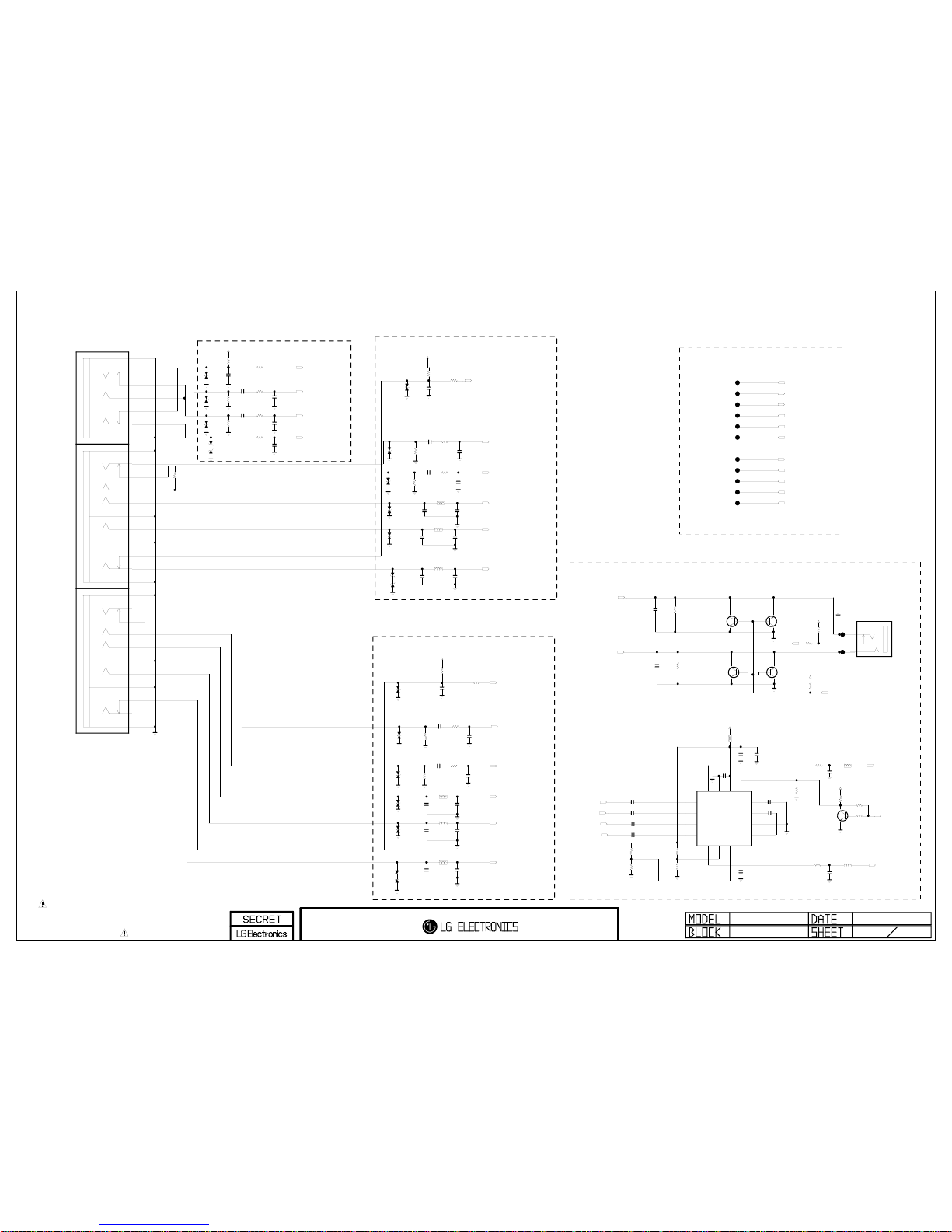
THE SYMBOL MARK OF THIS SCHEMETIC DIAGRAM INCORPORATES
SPECIAL FEATURES IMPORTANT FOR PROTECTION FROM X-RADIATION.
FILRE AND ELECTRICAL SHOCK HAZARDS, WHEN SERVICING IF IS
ESSENTIAL THAT ONLY MANUFATURES SPECFIED PARTS BE USED FOR
THE CRITICAL COMPONENTS IN THE SYMBOL MARK OF THE SCHEMETIC.
09/10/19
HP/COMP/REAR AV(NON_EU_CN)
11
GP2_BCM
HP_LOUT
R1113
0
C1112
100pF
50V
R1105
0
R1116
1K
+3.3V_NORMAL
C1123
27pF
50V
R1124
10K
OPT
D1102
5.6V
C11011uF
25V
C1105
47pF
50V
D1110
5.6V
D1111
5.5V
SC1_L_IN
C1104
100pF
50V
C1124
100pF
C1120
27pF
50V
L1102
270nH
D1114
5.6V
R1119
1K
D1105
5.6V
R1125
10K
HP_ROUT
D1100
5.6V
SC1_R_IN
C1117
1uF
25V
R1114
0
SC1_R
C1114
1uF
25V
JK1100
PPJ237-01
5J
[GN3]O-SPRING
6J
[GN3]E-LUG
4J
[GN3]CONTACT
7K
[BL3]E-LUG-S
5K
[BL3]O-SPRING
7L
[RD3]E-LUG-S
5L
[RD3]O-SPRING_1
5M
[WH3]O-SPRING
4N
[RD3]CONTACT
5N
[RD3]O-SPRING_2
6N
[RD3]E-LUG
6D
[GN2]E-LUG
5D
[GN2]O-SPRING
4D
[GN2]CONTACT
7E
[BL2]E-LUG-S
5E
[BL2]O-SPRING
7F
[RD2]E-LUG-S
5F
[RD2]O-SPRING_1
5G
[WH2]O-SPRING
4H
[RD2]CONTACT
5H
[RD2]O-SPRING_2
6H
[RD2]E-LUG
6A
[YL1]E-LUG
5A
[YL1]O-SPRING
4A
[YL1]CONTACT
5B
[WH1]O-SPRING
4C
[RD1]CONTACT
5C
[RD1]O-SPRING
6C
[RD1]E-LUG
R1103
470K
L1103
270nH
C1125
100pF
+3.3V_NORMAL
R1108
470K
R1117
0
D1112
5.5V
C1100
100pF
50V
C1113
1uF
25V
D1107
5.5V
C1130
1000pF
50V
OPT
R1100
0
OPT
COMP2_DET
D1104
5.6V
SIDE_HP_MUTE
C1122
27pF
50V
COMP2_Pb
R1110
470K
D1109
5.6V
JK1101
KJA-PH-0-0177
3DETECT
4L
5GND
1R
R1111
470K
Q1100
MMBT3904-(F)
OPT
E
B
C
Q1102
MMBT3904-(F)
OPT
E
B
C
R1118
0
COMP2_R_IN
C1103
100pF
50V
C1115
100pF
50V
C11021uF
25V
AV_CVBS_DET
9:G3
C1109
27pF
50V
R1102
470K
R1109
470K
SC1_B
R1106
0
D1115
5.6V
+3.5V_ST
C1119
27pF
50V
C1121
27pF
50V
COMP2_Y
C1106
27pF
50V
L1104
270nH
COMP2_L_IN
L1105
270nH
L1101
270nH
Q1103
MMBT3904-(F)
OPT
E
B
C
HP_DET
C1107
27pF
50V
+3.3V_NORMAL
Q1101
MMBT3904-(F)
OPT
E
B
C
C1127
100pF
D1106
5.5V
COMP2_Pr
R1122
1K
OPT
C1131
1000pF
50V
OPT
C1108
27pF
50V
R1123
1K
R1104
1K
L1100
270nH
REAR_AV_CVBS
11:C4;AL18
C1118
27pF
50V
C1111
27pF
50V
REAR_AV_L_IN
10:B5;AF22
C1126
100pF
R1107
0
D1101
5.6V
C1110
27pF
50V
R1121
1K
OPT
REAR_AV_R_IN
10:B5;AF24
SCART1_DET
C1116
1uF
25V
SC1_G
+3.3V_NORMAL
DTV/MNT_V_OUT
SC1_FB
TP1100
TP1101
SC1_ID
TP1102
DTV_ATV_SELECT
TP1103
SCART1_Rout_P
SCART1_Rout_N
TP1104
TP1105
SC1_CVBS_IN
TP1107
SC_RE2
SC_RE1
TP1108
TP1109
SCART1_Lout_P
SCART1_Lout_N
TP1110
TP1111
R1115
10K
R1101
10K
R1112
10K
C1139
0.1uF
16V
HP_LOUT_N
R1129
OPT
100K
SIDE_HP_MUTE
C1134
1uF
10V
R1133
0
OPT
HP_ROUT
L1106
10uH
HP_LOUT_P
C1140
2.2uF
10V
R1128
OPT
HP_ROUT_P
IC1100
TPA6132A2
EAN60724701
3
INR+
2
INL+
4
INR-
1
INL-
5
OUTR
6G07G18
HPVSS
9
CPN
10
PGND
11
CPP
12
HPVDD
13
EN14VDD15SGND16OUTL
R1127
4.7K
R1134
1K
C1132
1uF
10V
C1137
10uF
10V
R1132
4.7K
L1107
BG2012B080TF
C1136
1uF
10V
Q1104
2SC3052
E
B
C
HP_ROUT_N
C1135
1uF
10V
L1108
BG2012B080TF
HP_LOUT
C1138
2.2uF
10V
R1120
4.7K
R1126
OPT
+3.3V_NORMAL
+3.3V_NORMAL
C1141
2.2uF
10V
C1133
1uF
10V
D1103
5.1V
D1116
5.1V
D1108
5.1V
D1117
5.1V
D1113
5.1V
D1118
5.1V
R1130
0
1/16W
R1131
0
1/16W C1142
0.22uF
16V
C1143
0.22uF
16V
AV
New Item Development
EARPHONE BLOCK
COMPONENT1
COMPONENT2
AV1
COMPONENT2
<Practically COMP1>
NON_SCART
EARPHONE AMP
==> COMP1_DET
==> COMP1_R_IN
==> COMP1_L_IN
==> COMP1_Y
==> COMP1_Pb
==> COMP1_Pr
COMPONENT1
<Practically COMP2>
Close to the IC
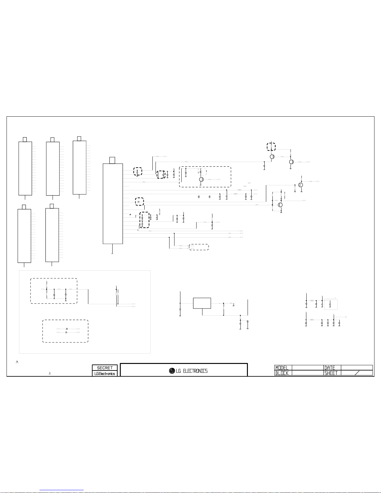
THE SYMBOL MARK OF THIS SCHEMETIC DIAGRAM INCORPORATES
SPECIAL FEATURES IMPORTANT FOR PROTECTION FROM X-RADIATION.
FILRE AND ELECTRICAL SHOCK HAZARDS, WHEN SERVICING IF IS
ESSENTIAL THAT ONLY MANUFATURES SPECFIED PARTS BE USED FOR
THE CRITICAL COMPONENTS IN THE SYMBOL MARK OF THE SCHEMETIC.
+3.3V_TU
IF_AGC_SEL
Q2601
ISA1530AC1
E
B
C
R2604 0
INT_DEMOD
TU_SIF
R2602 0
R2623
10K
C2600
100pF
50V
R2608
10K
OPT
C2605
100pF
50V
R2621
10K
C2607
0.1uF
16V
LNA2_CTL/BOSTER_CTL
C2610
0.1uF
16V
R2606
100
Q2602
ISA1530AC1
E
B
C
R2622
4.7K
R2615
0
R2600 0
OPT
R2612 100
NIM
TU_CVBS
C2603
0.1uF
16V
+5V_TU
IF_P_EXT
C2608
0.1uF
16V
OPT
R2611 100
NIM
C2606
0.1uF
16V
C2602
0.1uF 16V
R2616
200
R2605 0
TUNER_RESET
+5V_TU
Q2600
2SC3052
OPT
E
B
C
C2604
100pF
50V
IF_AGC
R2626
82
R2601 0
C2609
10uF
10V
OPT
C2613
0.01uF
25V
R2607
100K
+1.2V_TU
+5V_TU
Q2604
2SC3052
E
B
C
+5V_TU
L2600
BLM18PG121SN1D
R2613 0
Q2605
ISA1530AC1
E
B
C
IF_N_EXT
TU_IF_N_BCM
C2601
0.1uF
16V
+3.3V_TU
R2625
470
TU_IF_P_BCM
R2619
200
R2603 0
INT_DEMOD
R2614
1K
OPT
RF_SWITCH_CTL
R2618
2.2K
C2622
0.1uF
16V
+3.3V_TU
C2626
22uF
10V
C2620
0.1uF
16V
C2625
22uF
10V
+3.3V_NORMAL
L2603
BLM18PG121SN1D
+5V_TU
C2623
0.1uF
16V
C2621
0.1uF
16V
+5V_NORMAL
L2604
CIC21J501NE
R2641 510
R2632
3.9K
1/16W
5%
TU_IF_N_1
R2624
3.9K
1/16W
5%
R2642 510
READY
R2633
2K
1/16W
5%
TU_IF_AGC_2
TU_IF_P_1
C2629
0.01uF
A3.3V
R2638
220
1/16W
5%
TU_IF_N_BCM
C26310.01uF
TU_IF_AGC_BCM
C26320.01uF
+5V_NORMAL
TU_IF_P_BCM
C2627
0.01uF
TU_IF_AGC_1
C2614
0.1uF
16V
+1.2V_TU
C2615
10uF
10V
R2627
1.2K
IC2600
AZ1117H-ADJTRE1(EH11A)
2
OUTPUT
3
INPUT
1
ADJ/GND
GND
R2628
10
C2616
0.1uF
16V
R2629
1
+3.3V_TU
C2633
0.1uF
16V
TU2600
TDTR-T055F
Taiwan/Brazil_V
14
+B3[3.3V]
13
+B2[1.2V]
5
AS
12
GND
11
VIDEO
2
BST_CNTL
10
NC
4
NC[RF_AGC]
1
ANT_PWR[OPT]
17
DIF_1[N]
9
SIF
8
NC(IF_TP)
3
+B[5V]
16
IF_AGC_CNTL
7
SDA
6
SCL
15
RESET
18
DIF_2[P]
19
SHIELD
TU2600-*3
TDTJ-S031D
AU_Asia_Tuner_V
14
3.3V
13
1.2V
5
AS
12
GND
11
VIDEO
2
BST_CNTL
10
NC
4
NC[RF_AGC]
1
ANT_PWR[OPT]
17
DIF_1
9
SIF
8
NC(IF_TP)
3
+B
16
IF_AGC_CNTL
7
SDA
6
SCL
15
RESET
18
DIF_2
19
SHIELD
TU2600-*4
TDTJ-S001D
AU_Asia_Tuner_H
14
3.3V
13
1.2V
5
AS
12
GND
11
VIDEO
2
BST_CNTL
10
NC
4
NC[RF_AGC]
1
ANT_PWR[OPT]
17
DIF_1
9
SIF
8
NC[IF_TP]
3
+B
16
IF_AGC_CNTL
7
SDA
6
SCL
15
RESET
18
DIF_2
19
SHIELD
R2643
1K
OPT
R2644 0
OPT
TU2600-*5
TDTR-T035F
Taiwan/Brazil_H
14
+B3[3.3V]
13
+B2[1.2V]
5
NC_2
12
GND
11
VIDEO
2
BST_CTL
10
NC_4
4
NC_1[RF_AGC]
1
RF_S/W_CTL
17
DIF_1[N]
9
SIF
8
NC_3
3
+B1[5V]
16
IF/AGC
7
SDAT
6
SCLT
15
RESET
18
DIF_2[P]
19
SHIELD
TU2600-*1
TDVJ-H031F
Latin_Tuner_V
14
3.3V
13
1.2V
5
AS
12
GND
11
VIDEO
2
BST_CNTL
10
NC
4
NC[RF_AGC]
1
ANT_PWR[OPT]
17
DIF_1
9
SIF
8
NC(IF_TP)
3
+B
16
IF_AGC_CNTL
7
SDA
6
SCL
15
RESET
18
DIF_2
19
SHIELD
TU2600-*2
TDVJ-H001F
Latin_Tuner_H
14
3.3V
13
1.2V
5
AS
12
GND
11
VIDEO
2
BST_CNTL
10
NC
4
NC[RF_AGC]
1
ANT_PWR[OPT]
17
DIF_1
9
SIF
8
NC(IF_TP)
3
+B
16
IF_AGC_CNTL
7
SDA
6
SCL
15
RESET
18
DIF_2
19
SHIELD
L2605
BLM18PG121SN1D
C2634
10uF
10V
C2635
10uF
10V
C2636
22uF
10V
C2637
0.1uF
16V
SDA0_3.3V
C2638
20pF
50V
TUNER_I2C_LPF
L2609-*1
33
NON_TUNER_I2C_LPF
C2639
20pF
50V
TUNER_I2C_LPF
L2610-*1
33
NON_TUNER_I2C_LPF
C2611
62pF
50V
TUNER_I2C_LPF
L2609
TUNER_I2C_LPF270nH
SCL0_3.3V
C2612
62pF
50V
TUNER_I2C_LPF
L2610
TUNER_I2C_LPF270nH
C2612-*1
18pF
50V
NON_TUNER_I2C_LPF
C2611-*1
18pF
50V
NON_TUNER_I2C_LPF
C2624
10uF
16V
Tuner (Half Nim)
GP2_BCM Ver. 1.0
28
CAN H-NIM/NIM TUNER for TAIWAN
close to TUNER
OPTION : RF AGC
close to TUNER
60mA
200mA
IF AGC FILTER
IF FILTER OPTION
CAUTION : Closed BCM IC(IC100)
R2
R1
V_OUT=V_REF(1+R2/R1)
For ESD
close to TUNER
close to TUNER
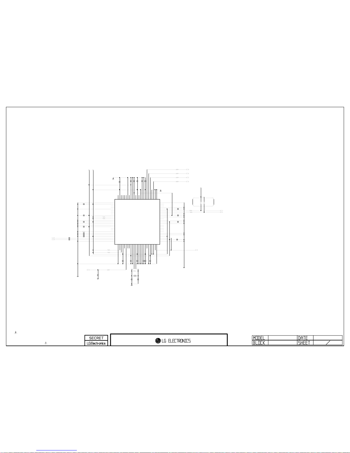
THE SYMBOL MARK OF THIS SCHEMETIC DIAGRAM INCORPORATES
SPECIAL FEATURES IMPORTANT FOR PROTECTION FROM X-RADIATION.
FILRE AND ELECTRICAL SHOCK HAZARDS, WHEN SERVICING IF IS
ESSENTIAL THAT ONLY MANUFATURES SPECFIED PARTS BE USED FOR
THE CRITICAL COMPONENTS IN THE SYMBOL MARK OF THE SCHEMETIC.
R2801 2.2K
ISDB_DEMOD
C2823
0.1uF
16V
ISDB_DEMOD
SDA1_3.3V
X2800
25MHz
ISDB_DEMOD
C2817
0.1uF
16V
ISDB_DEMOD
C2806 0.1uF
ISDB_DEMOD
R2802 2.2K
ISDB_DEMOD
R2800
10K
1%
ISDB_DEMOD
+3.3V_DE
IF_N_EXT
FE_TS_SERIAL
FE_TS_VAL_ERR
C2810
0.1uF
16V
ISDB_DEMOD
C2824 0.1uF
ISDB_DEMOD
R2805 2.2K
ISDB_DEMOD
FE_TS_SYNC
R2812
2.2K
OPT
C2818
15pF
50V
ISDB_DEMOD
C2802 0.1uF
ISDB_DEMOD
C2803 0.1uF
ISDB_DEMOD
C2826 0.1uF
ISDB_DEMOD
C2809
0.1uF
ISDB_DEMOD
DEMOD_RESET
C2805 0.1uF
ISDB_DEMOD
C2827 0.1uF
ISDB_DEMOD
FE_TS_DATA_CLK
C2814
15pF
50V
ISDB_DEMOD
IF_P_EXT
R2804 2.2K
ISDB_DEMOD
C2800 0.1uF
ISDB_DEMOD
R2809 22
ISDB_DEMOD
C2816
0.1uF
16V
ISDB_DEMOD
+3.3V_DE
C2807 0.1uF
ISDB_DEMOD
R2806
1M
ISDB_OPT
C2821
0.1uF
16V
ISDB_DEMOD
C2825 0.1uF
ISDB_DEMOD
C2820
0.1uF
16V
ISDB_DEMOD
IF_AGC_ISDB
C2819
0.1uF
16V
ISDB_DEMOD
C2812
0.1uF
16V
ISDB_DEMOD
+1.2V_DE
SCL1_3.3V
R2810 22
ISDB_DEMOD
R2808 22
ISDB_DEMOD
C2804 0.1uF
ISDB_DEMOD
C2813
0.1uF
16V
ISDB_DEMOD
R2803
10K
ISDB_DEMOD
C2811
0.1uF
16V
ISDB_DEMOD
C2801 0.1uF
ISDB_DEMOD
C2815
0.1uF
16V
ISDB_DEMOD
C2822
0.1uF
16V
ISDB_DEMOD
R2807 22
ISDB_DEMOD
R2811
2.2K
OPT
C2808 0.1uF
ISDB_DEMOD
R2813
22
R2814 22
IC2800
MN884433
ISDB_DEMOD
1
VSS_1
2
AVDD_S
3
AII_S
4
AIQ_S
5
AVSS_S
6
VRT_S
7
VRB_S
8
TCPO_S
9
VDDL_1
10
MSCL_S
11
MSDA_S
12
VSS_2
13
VSSH
14
PSEL
15
ZSEL
16
VDDL_2
17
ACKI
18
TCPO_T
19
IR_T
20
VRT_T
21
VRB_T
22
AVDD_T
23
AIN_T
24
AIP_T
25
AVSS_T
26
VSS_3
27
MSCL_T28MSDA_T29VDDH_1
30
GPO1
31
AGCI_T32AGCR_T
33
GPO0
34
VDDL_3
35
VSS_4
36XO37XI38
VDDH_2
39
GPI140GPI0
41
TEST442SHVPP
43
SHVDDH
44
NC_1
45
VSS_5
46
VDDL_4
47
TCK48TDI
49
NRST
50
TEST3
51
VSS_6
52
VDDL_5
53
TRST
54
TMS
55
CSEL0
56
CSEL1
57
TDO
58
SYNCA
59
ERRA
60
SYNCB
61
ERRB
62
VSS_7
63
VDDL_6
64
SADR_T
65
NC_2
66
SADR_S
67
HDVDDL0
68
VSS_8
69
SDA
70
SCL
71
VDDH_3
72
SADR
73
INTA
74
INTB
75
VSS_9
76
TEST177TEST278SCKA79GPI280SDOA81PCKA82DENA83VDDH_484VSS_1085HDVPP86RON87NC_388HDVDDH89NC_490HDVDDL191VSS_1192VDDL_793SCKB94TEST095SDOB96PCKB97DENB98GPO299VDDH_5
100
AGC_S
ISDB-T Demodulator
GP2_Saturn7M Ver. 1.0
28
AMP_I2C HAVE PULL-UP
(FE_TS_SERIAL)
PANASONIC (ISDB-T)
MN884433

THE SYMBOL MARK OF THIS SCHEMETIC DIAGRAM INCORPORATES
SPECIAL FEATURES IMPORTANT FOR PROTECTION FROM X-RADIATION.
FILRE AND ELECTRICAL SHOCK HAZARDS, WHEN SERVICING IF IS
ESSENTIAL THAT ONLY MANUFATURES SPECFIED PARTS BE USED FOR
THE CRITICAL COMPONENTS IN THE SYMBOL MARK OF THE SCHEMETIC.
C2905
22uF
16V
ISDB_POWER
C2904
0.1uF
16V
ISDB_POWER
IC2900
SC4215ISTRT
ISDB_POWER
3
VIN
2
EN
4
NC_2
1
NC_1
5
NC_3
6
VO
7
ADJ
8
GND
+3.3V_DE
IF_AGC
L2900
BLM18PG121SN1D
ISDB_POWER
C2902
0.1uF
16V
ISDB_POWER
R2900
0
ISDB_DEMOD
R2902
10K
ISDB_POWER
R2901
0
INT_DEMOD
IF_AGC_ISDB
+3.3V_DE
C2903
10uF
10V
ISDB_POWER
R2903
5.1K
ISDB_POWER
TP2901
C2900
0.1uF
ISDB_POWER
IF_AGC_SEL
TU_IF_AGC_BCM
C2901
0.1uF
ISDB_POWER
+3.3V_NORMAL
+1.2V_DE
Demodulator
GP2_Saturn7M Ver. 1.0
29
IF AGC SELECTION
Panasonic Demodulator Power(3.3V,1.2V)
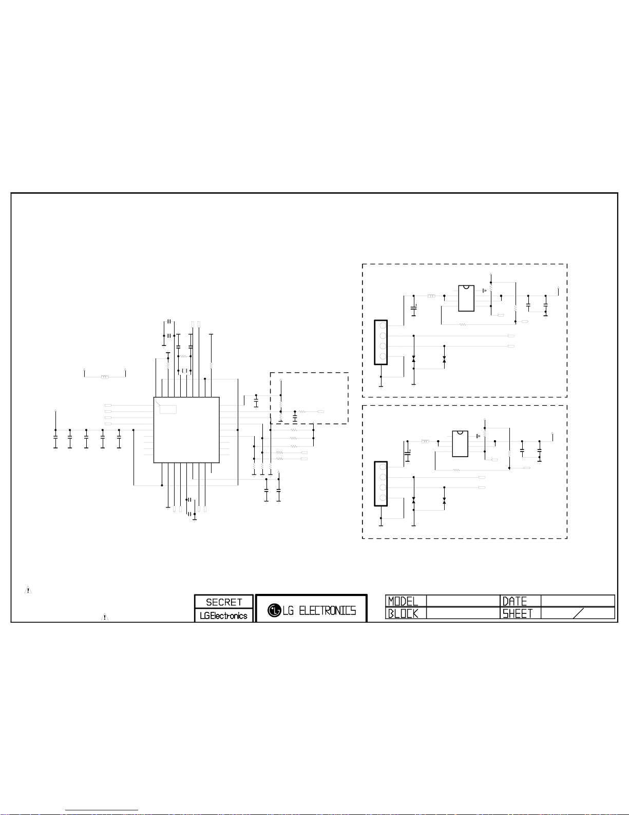
USB DOWN STREA M
THERMAL
USB DOWN STREA M
THE SYMBOL MARK OF THIS SCHEMETIC DIAGRAM INCORPORATES
SPECIAL FEATURES IMPORTANT FOR PROTECTION FROM X-RADIATION.
FILRE AND ELECTRICAL SHOCK HAZARDS, WHEN SERVICING IF IS
ESSENTIAL THAT ONLY MANUFATURES SPECFIED PARTS BE USED FOR
THE CRITICAL COMPONENTS IN THE SYMBOL MARK OF THE SCHEMETIC.
USB
C2205
0.1uF
SCL2_3.3V
USB_DP2
+3.3V_USB
USB_DM2
+3.3V_USB
C2201
1uF
10V
C2211
0.1uF
C2209
1uF
10V
USB_DP1
C2215
0.1uF
OPT
D2204
5.6V
CDS3C05HDMI1
R2212 100K
OPT
C2214
4.7uF
R2206
100K
C2203
0.1uF
R2208
0
OPT
R2202
1M
1%
C2207
0.1uF
R2205
100K
+3.3V_USB
R2213 100K
OPT
/RST_HUB
C2204
0.1uF
SIDE_USB_DP
C2202
0.1uF
JK2202
KJA-UB-4-0004
1234
5
USB_DP2
+3.3V_USB
R2209
100K
OPT
R2210
100K
USB_DM1
/USB_OCD2
C2206
1uF
10V
/USB_OCD1
C2212
0.1uF
R2207
0
OPT
R2204
100K
D2202
5.6V
CDS3C05HDMI1
R2214
0
/USB_OCD1
USB_CTL1
USB_DM1
+3.3V_USB
+3.3V_NORMAL
R2203
100K
SDA2_3.3V
SIDE_USB_DM
L2201
BLM18PG121SN1D
D2203
5.6V
CDS3C05HDMI1
C2213
0.1uF
USB_CTL2
D2201
5.6V
CDS3C05HDMI1
R2211 100K
OPT
USB_DP1
USB_DM2
USB_CTL1
R2201
12K
1/10W 1%
IC2201
USB2512A_AEZG
1
USBDN1_DM
3
USBDN2_DM
7
NC_2
9
NC_4
10
VDDA33_2
11
TEST
12
PRTPWR1
13
OCS1_N
14
VDD18
15
VDD33CR16PRTPWR2
17
OCS2_N
18
NC_5
19
NC_6
20
NC_7
21
NC_8
22
SDA/SMBDATA/NON_REM1
23
VDD33
24
SCL/SMBCLK/CFG_SEL0
25
HS_IND/CFG_SEL1
26
RESET_N
27
VBUS_DET
28
SUSP_IND/LOCAL_PWR/NON_REM0
29
VDDA33_3
30
USBUP_DM
31
USBUP_DP32XTAL2
5
VDDA33_1
8
NC_3
6
NC_1
4
USBDN2_DP
2
USBDN1_DP
33
XTAL1/CLKIN
34
VDD18PLL
35
RBIAS36VDD33PLL
37
VSS
X2201
24MHz
C2208
15pF
C2210
15pF
C2218
100uF
16V
C2222
0.1uF
IC2202
AP2191SG-13
EAN60921001
3
IN_2
2
IN_1
4
EN
1
GND
5
FLG
6
OUT_1
7
OUT_2
8
NC
+5V_USB
R2226
2.7K
R2225 0
R2220
4.7K
OPT
+3.3V_NORMAL
C2220
10uF
10V
L2202
MLB-201209-0120P-N2
120-ohm
JK2201
KJA-UB-4-0004
1234
5
R2227 0
R2223
2.7K
C2223
0.1uF
R2221
4.7K
OPT
L2203
MLB-201209-0120P-N2
120-ohm
IC2203
AP2191SG-13
EAN60921001
3
IN_2
2
IN_1
4
EN
1
GND
5
FLG
6
OUT_1
7
OUT_2
8
NC
C2221
10uF
10V
+5V_USB
C2219
100uF
16V
+3.3V_NORMAL
/USB_OCD2
040:J6
USB_CTL2
USB2 OPTION
USB / DVR Ready
USB
40
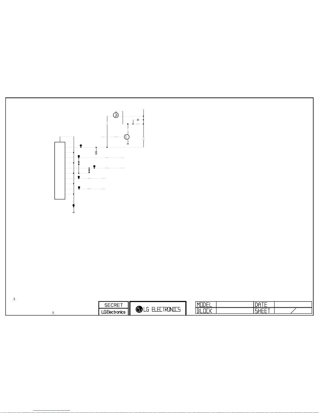
THE SYMBOL MARK OF THIS SCHEMETIC DIAGRAM INCORPORATES
SPECIAL FEATURES IMPORTANT FOR PROTECTION FROM X-RADIATION.
FILRE AND ELECTRICAL SHOCK HAZARDS, WHEN SERVICING IF IS
ESSENTIAL THAT ONLY MANUFATURES SPECFIED PARTS BE USED FOR
THE CRITICAL COMPONENTS IN THE SYMBOL MARK OF THE SCHEMETIC.
Bluetooth
P1895
12507WR-10L
BCM BT MODULE
1
2
3
4
5
6
7
8
9
10
11
+3.3V_NORMAL
R1896
27
BCM BT MODULE
R1897
27
BCM BT MODULE
R1898
0
BCM BT MODULE
VREG_CTRL
BT_RESET
R1899
0
BCM BT MODULE
BT_DP
BT_DM
D1898
5.6V
CDS3C05HDMI1
BCM BT MODULE
D1899
5.6V
CDS3C05HDMI1
BCM BT MODULE
R1889
10
BCM BT MODULE
Q1801
RTR030P02
BCM BT MODULE
S
D
G
Q1800
2SC3052
BCM BT MODULE
E
B
C
BT_ON/OFF
R1887
47K
BCM BT MODULE
R1886
47K
BCM BT MODULE
R1888
4.7K
BCM BT MODULE
L1899
500
OPT
C1898
1uF
BCM BT MODULE
C1899
22uF
10V
BCM BT MODULE
BLUETOOTH FOR BCM
43
BLUETOOTH

THE SYMBOL MARK OF THIS SCHEMETIC DIAGRAM INCORPORATES
SPECIAL FEATURES IMPORTANT FOR PROTECTION FROM X-RADIATION.
FILRE AND ELECTRICAL SHOCK HAZARDS, WHEN SERVICING IF IS
ESSENTIAL THAT ONLY MANUFATURES SPECFIED PARTS BE USED FOR
THE CRITICAL COMPONENTS IN THE SYMBOL MARK OF THE SCHEMETIC.
Non_CI
2009.10.19
CI_A[0]
CI_A[1]
CI_A[2]
CI_A[3]
CI_A[4]
CI_A[5]
CI_A[6]
CI_A[7]
CI_A[8]
CI_A[9]
CI_A[10]
CI_A[11]
CI_A[12]
CI_A[13]
CI_OUTDATA[4]
CI_OUTDATA[5]
CI_OUTDATA[6]
CI_OUTDATA[7]
CI_OUTCLK
CI_OUTVALID
CI_OUTSTART
CI_OUTDATA[0]
CI_OUTDATA[1]
CI_OUTDATA[2]
CI_OUTDATA[3]
CI_OUTCLK
/CI_WAIT
CI_MOD_RESET
[GP49]
/CI_CD2
[GP38]
CI_MOD_RESET
/CI_CD1
FE_TS_DATA_CLK
FE_TS_VAL_ERR
/CI_WAIT
/CI_IREQ
[GP39]
007:H5;016:AJ3
/CI_CD1
CI_OUTCLK,CI_OUTDATA[0-7],CI_OUTSTART,CI_OUTVALID
FE_TS_SYNC
/CI_CD2
EBI_RW
007:E6
CI_5V_CTL
[GP27]007:H7
CI_A[0-13]
EBI_WE
/CI_SEL
CI_A[14]
EBI_CS
High_Common(BCM3556)
46
DVB-CI PULL-UP (Near CI Slot)
DVB-CI PULL-DOWN (Near CI Slot)
CI POWER ENABLE CONTROL
CI CONTROL BUFFER
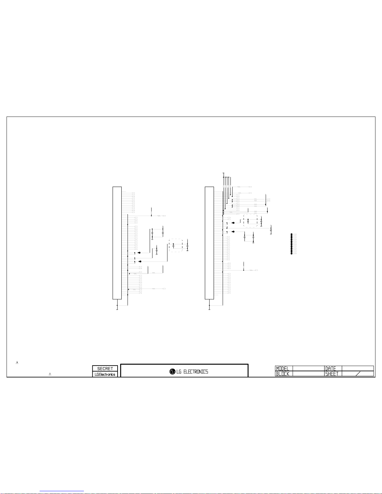
THE SYMBOL MARK OF THIS SCHEMETIC DIAGRAM INCORPORATES
SPECIAL FEATURES IMPORTANT FOR PROTECTION FROM X-RADIATION.
FILRE AND ELECTRICAL SHOCK HAZARDS, WHEN SERVICING IF IS
ESSENTIAL THAT ONLY MANUFATURES SPECFIED PARTS BE USED FOR
THE CRITICAL COMPONENTS IN THE SYMBOL MARK OF THE SCHEMETIC.
GMA12
VGI_N
CLK1
GMA3
RRXB3+/RLV1P
VCC_LCM
R7507 0
NON_GIP
CLK5
R7500
0
GIP
C7508
0.1uF
50V
MINI_LVDS
Z_OUT
VGI_N
POL
RRXB4-/RLV0N
VCOMR
GVDD_ODD_I/GSC
VCOML
OPC_EN
R7512
0
NON_GIP
LLV3N
VDD_ODD
RRXB2-
GMA18
VDD_LCM
RRXB1-
GVST_I/GSP
C7500
0.1uF
16V
MINI_LVDS
VST
RRXA3-
R7513
0
NON_GIP
GCLK4/OPT_P
Z_OUT
C7505
0.1uF
16V
MINI_LVDS
VGI_P
GMA6
RRXA0-
R7501
0
GIP
LLCLKN
R7506 0
NON_GIP
CLK4
CLK6
GMA15
RRXA1+
RRXB0-/RLCLKN
CLK4
VDD_ODD
GMA9
R7505 0
NON_GIP
RRXB4+/RLV0P
LLV0N
GMA16
R7515
0
NON_GIP
GMA9
H_CONV
GMA7
R7508
0
GIP
LLV4N
GMA15
VDD_EVEN
GMA18
OPT_N
CLK1
GMA6
GMA10
VCOMRFB
GMA1
RRXBCK-/RLV2N
RRXACK-/RLV4N
LLV5N
GMA13
LLV0P
RRXBCK+/RLV2P
GVST_I/GSP
CLK3
GMA4
SOE
POL
C7504
0.1uF
50V
MINI_LVDS
C7501
10uF
16V
MINI_LVDS
OPC_OUT
C7502
0.01uF
50V
MINI_LVDS
CLK3
RRXA2-/RLV5N
SOE
R7517
0
NON_GIP
RRXB1+
GMA1
VGL
(-5V)
P7501
104060-6017
TM240Hz
1 GND
2 Z_OUT
3 CLK1
4 CLK2
5 CLK3
6 CLK4
7 CLK5
8 CLK6
9 VGI_N
10 VGI_P
11 VGH_ODD
12 VGH_EVEN
13 VSS
14 VST
15 GND
16 VCOM_FB
17 VCOM_IN
18 GND
19 VDD
20 VDD
21 HALF_VDD
22 HALF_VDD
23 GND
24 VCC
25 VCC
26 GND
27 RV0+
28 RV029 RV1+
30 RV131 RV2+
32 RV233 RVCLK+
34 RVCLK35 RV3+
36 RV337 RV4+
38 RV439 RV5+
40 RV541 GND
42 SOE
43 POL
44 VST_IN
45 H_CONV
46 OPT_N
47 GND
48 GMA18
49 GMA16
50 GMA15
51 GMA13
52 GMA12
53 GMA10
54 GMA9
55 GMA7
56 GMA6
57 GMA4
58 GMA3
59 GMA1
60 GND
61
.
VDD_EVEN
GMA3
RRXB2+
RRXA3+
RRXA4-/RLV3N
VGL_I
CLK2
R7503
0
NON_GIP
RRXA0+
LLCLKP
CLK2
VGI_P
R7509 0
NON_GIP
GMA16
LLV1P
GMA4
R7511 0
MINI_LVDS
RRXA1-
GMA12
RRXB3-/RLV1N
RRXACK+/RLV4P
RRXB0+/RLCLKP
GVDD_EVEN_I/GOE
LLV2N
R7502
0
NON_GIP
LLV1N
LLV3P
VGL_I
GMA7
RRXA4+/RLV3P
VGH_M
(+25V)
HVDD
P7500
104060-6017
TM240Hz
1 GND
2 GMA1
3 GMA3
4 GMA4
5 GMA6
6 GMA7
7 GMA9
8 GMA10
9 GMA12
10 GMA13
11 GMA15
12 GMA16
13 GMA18
14 GND
15 OPT_N
16 H_CONV
17 VST_IN
18 POL
19 SOE
20 GND
21 LV0+
22 LV023 LV1+
24 LV125 LV2+
26 LV227 LVCLK+
28 LVCLK29 LV3+
30 LV331 LV4+
32 LV433 LV5+
34 LV535 GND
36 VCC
37 VCC
38 GND
39 HALF_VDD
40 HALF_VDD
41 VDD
42 VDD
43 GND
44 VCOM_IN
45 VCOM_FB
46 GND
47 VST
48 VSS
49 VGH_EVEN
50 VGH_ODD
51 VGI_P
52 VGI_N
53 CLK6
54 CLK5
55 CLK4
56 CLK3
57 CLK2
58 CLK1
59 Z_OUT
60 GND
61
.
LLV4P
GMA13
VCOMLFB
HVDD
LLV2P
C7509
10uF
16V
MINI_LVDS
R7504 0
NON_GIP
VST
C7507
0.01uF
50V
MINI_LVDS
H_CONV
CLK5
RRXA2+/RLV5P
GMA10
LLV5P
VCC_LCM
VGL
(-5V)
R7510
0
NON_GIP
CLK6
R7516
0
NON_GIP
R7514
0
NON_GIP
VDD_LCM
VCC_LCM
R7520
510
OPT
R7521
0
MINI_LVDS
OPT_N
R7519
0
MINI_LVDS
OPT_N
VCC_LCM
R7518
510
OPT
C7503
1uF
50V
MINI_LVDS
C7506
1uF
50V
MINI_LVDS
35
[Right FFC Connector]
(60Pin Mini-LVDS)
[LEFT FFC Connector]
(60Pin Mini-LVDS)
To reduce
Audible noise
(2012)
To reduce
Audible noise
(2012)
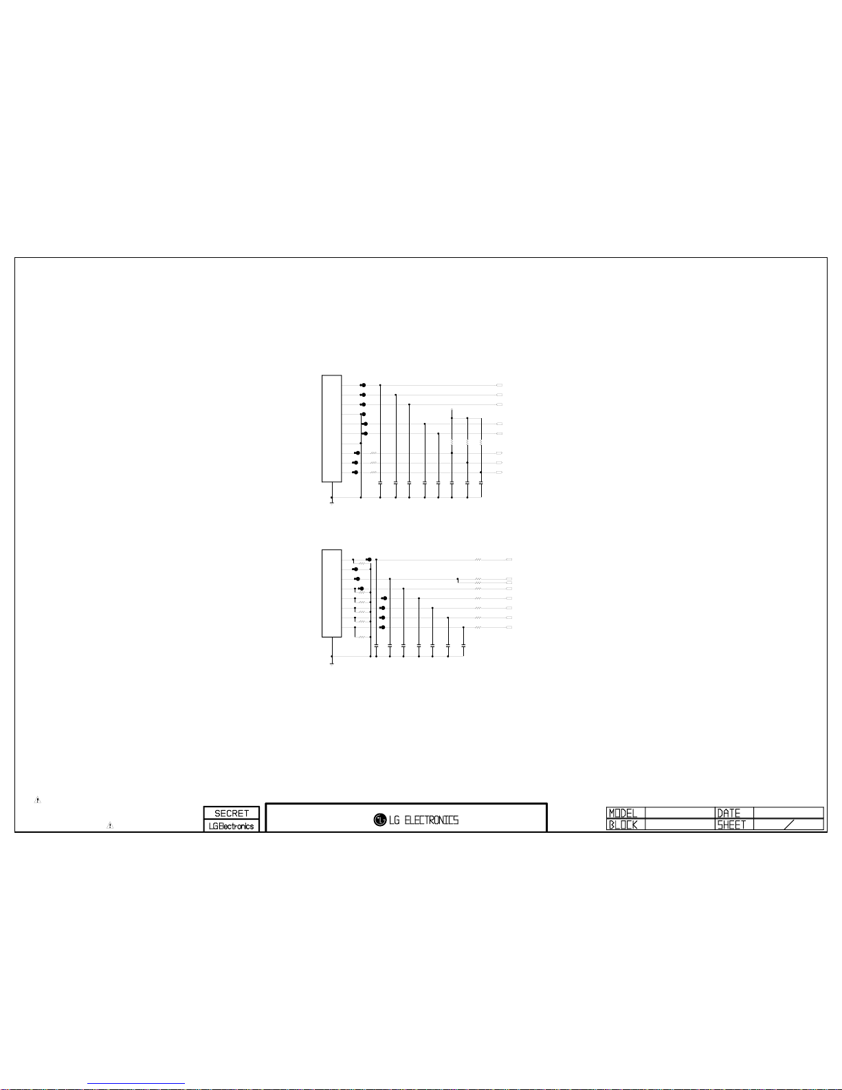
THE SYMBOL MARK OF THIS SCHEMETIC DIAGRAM INCORPORATES
SPECIAL FEATURES IMPORTANT FOR PROTECTION FROM X-RADIATION.
FILRE AND ELECTRICAL SHOCK HAZARDS, WHEN SERVICING IF IS
ESSENTIAL THAT ONLY MANUFATURES SPECFIED PARTS BE USED FOR
THE CRITICAL COMPONENTS IN THE SYMBOL MARK OF THE SCHEMETIC.
M2_SCLK
C7900
100pF
50V
OPT
R7907
3.3K
Edge
P7901
12507WR-08L
Except Edge(42/47")
1
2
3
4
5
6
7
8
9
S_CS_N
C7905
100pF
50V
OPT
C7914
100pF
50V
OPT
R_VS
M1_MOSI
M2_SCLK
+3.3V_NORMAL
P7900
12507WR-10L
IOP
1
2
3
4
5
6
7
8
9
10
11
M3_MOSI
C7913
100pF
50V
OPT
M0_MOSI
C7902
100pF
50V
OPT
C7904
100pF
50V
OPT
C7909
100pF
50V
OPT
M3_SCLK
C7912
100pF
50V
OPT
M0_SCLK
C7908
100pF
50V
OPT
L_VS
M2_MOSI
C7911
100pF
50V
OPT
C7903
100pF
50V
OPT
C7910
100pF
50V
OPT
C7907
100pF
50V
OPT
R_VS
R7908
3.3K
Edge
C7901
100pF
50V
OPT
S_MOSI
S_SCLK
C7906
100pF
50V
OPT
R7909
3.3K
Edge
M2_MOSI
M1_SCLK
R7916 22
Edge(55")
R7900 22
OPT
R7917 22
Edge(55")
R7901 22
Edge(55")
R7904 22
IOP
R7903 22
IOP
R7911 22
IOP
R7915 22
Edge(55")
R7918 22
IOP
R7914 22
Edge(55")
R7919 22
IOP
R7906 22
IOP
R7912 22
Edge(55")
R7910 22
IOP
R7913 22
IOP
R7905 22
IOP
R7902 22
IOP
GP2_Saturn7M
Interface for LG5111
Ver. 1.0
72
[To MASTER LED DRIVER]
[To SLAVE LED DRIVER]
 Loading...