

Page 1
1080P
Published October 8th, 2010
Direct View LCD
Training
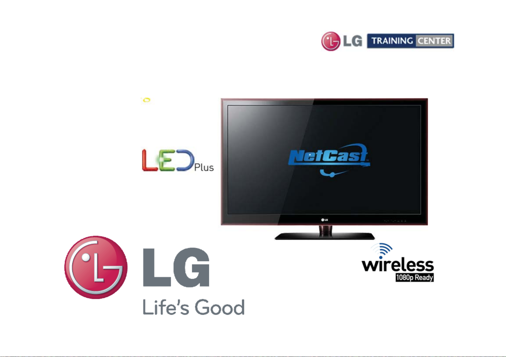
42LE5500
42LE5500
LED Backlights
LCD-DV Troubleshooting
42" Class Full HD 1080P
LCD TV (42" diagonally)
Page 2

OUTLINE
OUTLINE
Preliminary Section:
Disassembly Section: Removal of Circuit Boards
Contact Information, Preliminary Matters, Specifications,
LCD Overview, General Troubleshooting Steps,
Signal Distribution, Disassembly Instructions and Voltages
Troubleshooting Section:
• Switch Mode Power Supply with LED Backlight Driver Board
• Main Board
• Ft Control Board
• Soft Touch Keys
• Speakers
Board Operation Troubleshooting of :
2
October 2010 LCD TV 42LE5500
Page 3

Overview of Topics to be Discussed
Overview of Topics to be Discussed
42LE5500 LCD Direct View Display
This Section will cover Contact Information and remind the Technician of Important
Safety Precautions for the Customers Safety as well as the Technician and the
Equipment.
Basic Troubleshooting Techniques which can save time and money sometimes can
be overlooked. These techniques will also be presented.
This Section will get the Technician familiar with the Disassembly, Identification and
Section 1
Layout of the LCD Display Panel.
At the end of this Section the Technician should be able to Identify the Circuit Boards
and have the ability and knowledge necessary to safely remove and replace any
Circuit Board or Assembly.
3
October 2010 LCD TV 42LE5500
Page 4

IMPORTANT SAFETY NOTICE
IMPORTANT SAFETY NOTICE
CAUTION
CAUTION
Preliminary Matters (The Fine Print)
Preliminary Matters (The Fine Print)
The information in this training manual is intended for use by persons possessing an adequate background in
electrical equipment, electronic devices, and mechanical systems. In any attempt to repair a major Product,
personal injury and property damage can result. The manufacturer or seller maintains no liability for the
interpretation of this information, nor can it assume any liability in conjunction with its use. When servicing this
product, under no circumstances should the original design be modified or altered without permission from LG
Electronics. Unauthorized modifications will not only void the warranty, but may lead to property damage or
user injury. If wires, screws, clips, straps, nuts, or washers used to complete a ground path are removed for
service, they must be returned to their original positions and properly fastened.
To avoid personal injury, disconnect the power before servicing this product. If electrical power is required for
diagnosis or test purposes, disconnect the power immediately after performing the necessary checks. Also be
aware that many household products present a weight hazard. At least two people should be involved in the
installation or servicing of such devices. Failure to consider the weight of an product could result in physical
injury.
4
October 2010 LCD TV 42LE5500
Page 5

Regulatory Information
Regulatory Information
ESD Notice
ESD Notice
(Electrostatic Static Discharge)
Today’s sophisticated electronics are electrostatic discharge (ESD) sensitive. ESD can weaken or damage
the electronics in a manner that renders them inoperative or reduces the time until their next failure.
Connect an ESD wrist strap to a ground connection point or unpainted metal in the product. Alternatively,
you can touch your finger repeatedly to a ground connection point or unpainted metal in the product. Before
removing a replacement part from its package, touch the anti-static bag to a ground connection point or
unpainted metal in the product. Handle the electronic control assembly by its edges only. When
repackaging a failed electronic control assembly in an anti-static bag, observe these same precautions.
This equipment has been tested and found to comply with the limits for a Class B digital device, pursuant to
Part 15 of the FCC Rules. These limits are designed to provide reasonable protection against harmful
interference when the equipment is operated in a residential installation. This equipment generates, uses,
and can radiate radio frequency energy, and, if not installed and used in accordance with the instruction
manual, may cause harmful interference to radio communications. However, there is no guarantee that
interference will not occur in a particular installation. If this equipment does cause harmful interference to
radio or television reception, which can be determined by turning the equipment off and on, the user is
encouraged to try to correct the interference by one or more of the following measures: Reorient or relocate
the receiving antenna; Increase the separation between the equipment and the receiver; Connect the
equipment to an outlet on a different circuit than that to which the receiver is connected; or consult the
dealer or an experienced radio/TV technician for help.
(Electrostatic Static Discharge)
5
October 2010 LCD TV 42LE5500
Page 6
LG Contact Information
LG Contact Information
Customer Service (and Part Sales) (800) 243-0000
Technical Support (and Part Sales) (800) 847-7597
USA Website (GSFS) http://gsfs-america.lge.com
Customer Service Website http://www.us.lgservice.com
Knowledgebase Website http://lgtechassist.com
LG Web Training https://lge.webex.com
LG CS Academy http://ln.lge.com/ilearn
LCD-DV:
PLASMA:
PDP Panel Alignment Handbook, Schematics with Bookmarks
32LG40, 32LH30, 37LH55, 42LG60, 42LG70, 42LH20, 42LH40, 42LH50, 42LH90, 42SL80,
47LG90, 47LH85, 42LE5500, 47LE8500
42PG20, 42PJ350, 42PQ20, 42PQ30, 50PG20, 50PJ350, 50PK250, 50PK750, 50PS80,
50PS60, 60PK750, 60PS11, 60PS60, 60PS80
Also available on the Plasma Page:
Plasma Control Board ROM Update (Jig required)
Published September 2010 by LG Technical Support and Training
LG Electronics Alabama, Inc.
201 James Record Road, Huntsville, AL, 35813.
New: 2010 Models Software
Downloads Technical Assistance
Presentations with Audio/Video
and Screen Marks
http://136.166.4.200
New Training Materials on
New Training Materials on
the Learning Academy site
the Learning Academy site
6
October 2010 LCD TV 42LE5500
Page 7

LCD Direct View Overview
LCD Direct View Overview
Safety and Handling Regulations
1. Approximately 20 minute pre-run time is required before making any picture performance
adjustments from the Menu.
2. Refer to the Voltage/Current silk screening on the Switch Mode Power Supply.
3. C-MOS circuits are sensitive to static electricity.
Use caution when dealing with these IC and circuits.
4. Exercise care when making voltage and waveform checks to prevent costly short circuits
from damaging the unit.
5. Be cautious of lost screws and other metal objects to prevent a possible short in the
circuitry.
Checking Points to be Considered
1. Check the appearance of the Replacement Panel and Circuit Boards for both physical
damage and part number accuracy.
2. Check the model label. Verify model names and board model matches.
3. Check details of defective condition and history. Example: Oscillator failure dead set, etc…
7
October 2010 LCD TV 42LE5500
Page 8

Basic Troubleshooting Steps
Basic Troubleshooting Steps
Define, Localize, Isolate and Correct
•Define
the failure. Use your senses Sight, Smell, Touch and Hearing. Look for burned parts and
check for possible overheated components. Capacitors will sometimes leak dielectric material
and give off a distinct odor. Frequency of power supplies will change with the load, or listen for
relay closing etc. Observation of the front Power LED may give some clues.
•Localize
checked and after giving a thorough examination using your senses the first check should
always be the DC Supply Voltages to those circuits under test. Always confirm the supplies
are not only the proper level but be sure they are noise free. If the supplies are missing check
the resistance for possible short circuits.
•Isolate
Oscilloscope to make a final determination of the failure. Look for correct Amplitude Phasing
and Timing of the signals also check for the proper Duty Cycle of the signals. Sometimes
“glitches” or “road bumps” will be an indication of an imminent failure.
Look at the symptom carefully and determine what circuits could be causing
After carefully checking the symptom and determining the circuits to be
To further isolate the failure, check for the proper waveforms with the
•Correct
check the DC Supplies for proper levels. Make all necessary adjustments and lastly always
perform a Safety AC Leakage Test before returning the product back to the Customer.
The final step is to correct the problem. Be careful of ESD and make sure to
8
October 2010 LCD TV 42LE5500
Page 9
42LE5500 PRODUCT INFORMATION SECTION
42LE5500 PRODUCT INFORMATION SECTION
This section of the manual will discuss the specifications of the
42LE5500
LCD Direct View Display
9
October 2010 LCD TV 42LE5500
Page 10
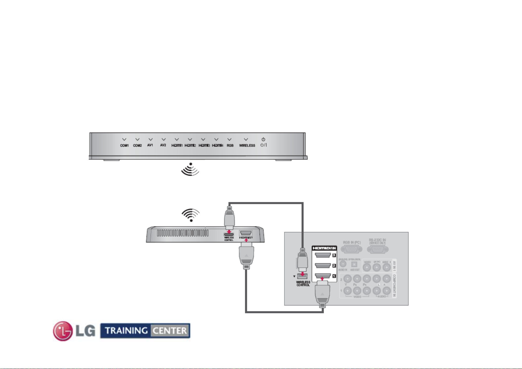
Wireless Media Box
Wireless Media Box
Wireless Media Box (Sold Separately)
The Wireless Media box communicates to the television via a wireless receiver
called a “Dongle”. The Dongle attaches to the Television via two connections:
1. HDMI Cable from the Dongle to the TV to transfer Audio and Video Signals.
2. Wired Remote cable between the TV and Dongle for Control Functions.
Media Box
Wired Remote to control the Media Box
Wireless Receiver/Transmitter
“Dongle”
Attaches via Velcro to
the back of the set
HDMI
10
TV A/V Inputs
October 2010 LCD TV 42LE5500
Page 11
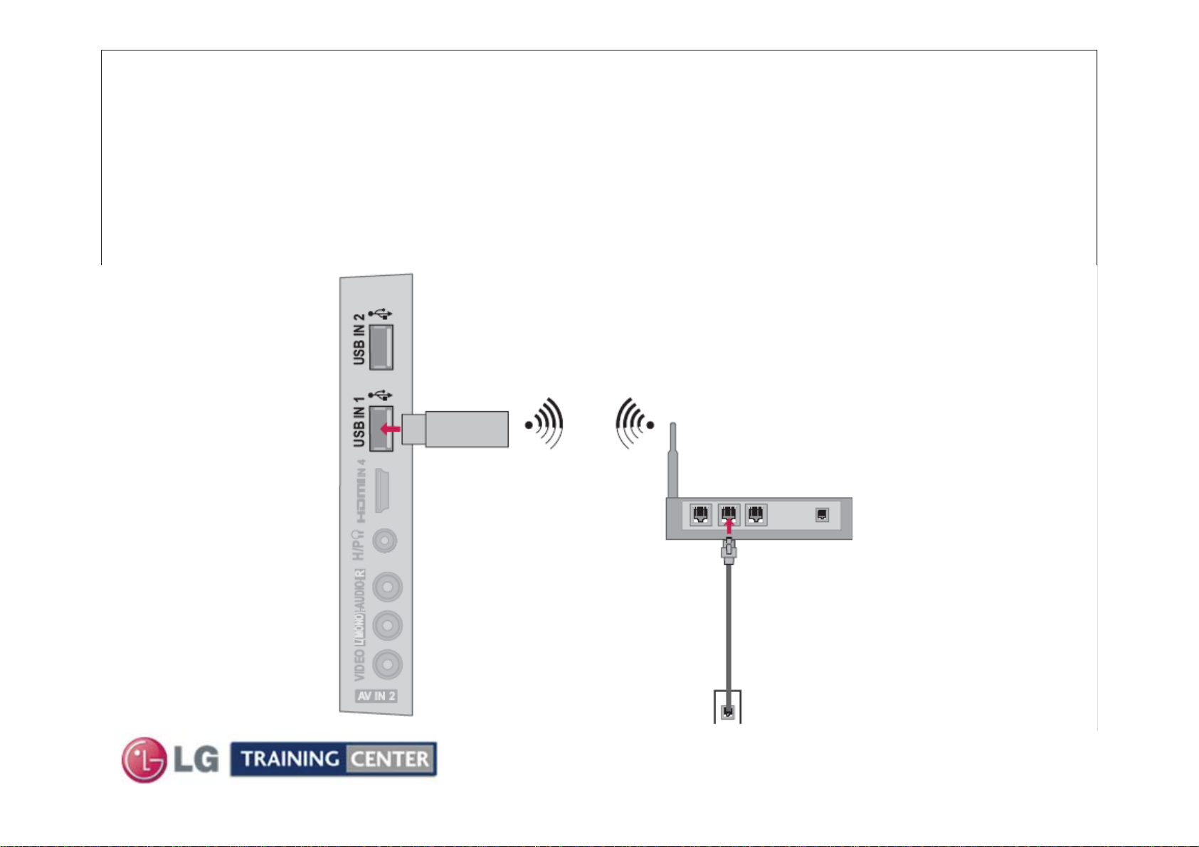
Wireless LAN (DLNA Adaptor)
Wireless LAN (DLNA Adaptor)
Wireless LAN (Sold Separately)
Using the LG Wireless LAN for Broadband/1DLNA Adaptor, which is sold separately, allows the TV
to connect to a wireless LAN network. The DLNA adaptor attaches to the Television via either of
the two USB connections:
1(DLNA: Digital Living Network Alliance)
Side A/V Inputs
DLNA Adaptor
“Dongle”
11
Wireless Router
October 2010 LCD TV 42LE5500
Page 12

Basic Specifications
Basic Specifications
Key TV Features
• LED Plus w/Local Dimming
• NetCast™ Entertainment Access*
(Wi-Fi® Ready)
• Wireless 1080p Ready*
• DLNA Certified®
• TruMotion 120Hz
• Full HD 1080p Resolution
• 5M:1 Dynamic Contrast Ratio
• Picture Wizard II
(Easy Picture Calibration)
• Smart Energy Saving
• ENERGY STAR® Qualified
• Intelligent Sensor
• AV Mode II
(Cinema, Sports, Game)
• Clear Voice II
• ISFccc® Ready
• 24P Real Cinema
• USB 2.0 (JPEG, MP3, DivX HD)
• DivX® HD
• 4 HDMI™ V.1.3 w/Deep Color
• SIMPLINK™ Connectivity
• Dolby® Digital 5.1 Decoder
• Infinite Sound
12
October 2010 LCD TV 42LE5500
Page 13

Logo Familiarization Page 1 of 4
Logo Familiarization Page 1 of 4
LED Plus
Prepare to be dazzled. Tired of dark scenes or dull colors?
LG’s LED Plus technology provides
even greater control of brightness through local
dimming to deliver amazing clarity and color
detail, as well as a more energy efficient TV
compared to conventional TVs.
TruMotion 120Hz
See sports, video games and high-speed action with virtually no motion blur and
in crystal clarity with LG’s TruMotion 120Hz technology. Now your TV can keep
up with the fastest moving scenes.
NetCast
Entertainment on tap. NetCast Entertainment Access
brings the best Internet services direct to your TV—no
computer required. Instantly access movies and TV
shows, news and weather and the world’s largest library of
HD movies in 1080p.
13
October 2010 LCD TV 42LE5500
Page 14

Logo Familiarization Page 2 of 4
Logo Familiarization Page 2 of 4
FULL HD RESOLUTION 1080P HD Resolution Pixels: 1920 (H) × 1080 (V)
Enjoy twice the picture quality of standard HDTV with almost double the pixel
resolution. See sharper details like never before. Just imagine a Blu-ray disc
or video game seen on your new LG Full HD 1080p TV.
HDMI (1.3 Deep Color) Digital multi-connectivity
HDMI (1.3 Deep color) provides a wider bandwidth (340MHz,
10.2Gbps) than that of HDMI 1.2, delivering a broader range of
colors, and also drastically improves the data-transmission
speed.
Invisible Speaker
Personally tuned by Mr. Mark Levinson for LG
TAKE IT TO THE EDGE newly introduces ‘Invisible Speaker’
system, guaranteeing first class audio quality personally tuned by
Mr. Mark Levinson, world renowned as an audio authority. It
provides Full Sweet Spot and realistic sound equal to that of
theaters with its Invisible Speaker.
AV Mode "One click" Cinema,
TAKE IT TO THE EDGE is a true multimedia TV with an AV Mode
which allows you to choose from 4 different modes of Cinema, Sports
and Game by a single click of a remote control.
THX
Cinema, Sport, Game mode.
14
October 2010 LCD TV 42LE5500
Page 15

Logo Familiarization Page 3 of 4
Logo Familiarization Page 3 of 4
Clear Voice Clearer dialogue sound
Automatically enhances and amplifies the sound of the human voice
frequency range to provide high-quality dialogue when background
noise swells.
Save Energy, Save Money
It reduces the plasma display’s power consumption.
The default factory setting complies with the Energy Star requirements
and is adjusted to the comfortable level to be viewed at home.
(Turns on Intelligent Sensor).
Save Energy, Save Money
Home electronic products use energy when they're off to power features like
clock displays and remote controls. Those that have earned the ENERGY
STAR use as much as 60% less energy to perform these functions, while
providing the same performance at the same price as less-efficient models.
Less energy means you pay less on your energy bill. Draws less than 1 Watt in
stand by.
15
October 2010 LCD TV 42LE5500
Page 16

Logo Familiarization Page 4 of 4
Logo Familiarization Page 4 of 4
Wireless Ready
Wireless 1080p Connectivity lets you cut loose from messy wires and
still get a stunning Full HD picture. Disclaimer: Wireless media kit
required and sold separately.
Picture Wizard
Get easy self-calibration with on-screen reference points for key picture
quality elements such as black level, color, tint, sharpness and
backlight levels. Take the guesswork out of picture adjustments with
this simple-to-use feature. It's not actually magic, but it will sure seem
that way.
5M:1 Dynamic Contrast Ratio
Worrying about dark scenes is a thing of the past. The mega contrast
ratio of 5,000,000:1 delivers vivid colors and deep blacks.
Intelligent Sensor
The Intelligent sensor will monitor the room lighting environment. When
the room lights go out, the TV will automatically adjust the picture for
the best view enjoyment.
16
October 2010 LCD TV 42LE5500
Page 17
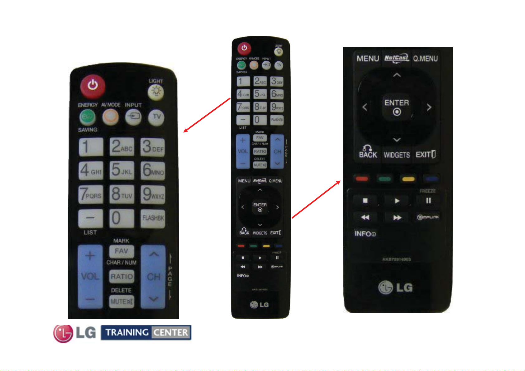
42LE5500 Remote Control
42LE5500 Remote Control
p/n AKB72914003
TOP PORTION
BOTTOM PORTION
17
October 2010 LCD TV 42LE5500
Page 18
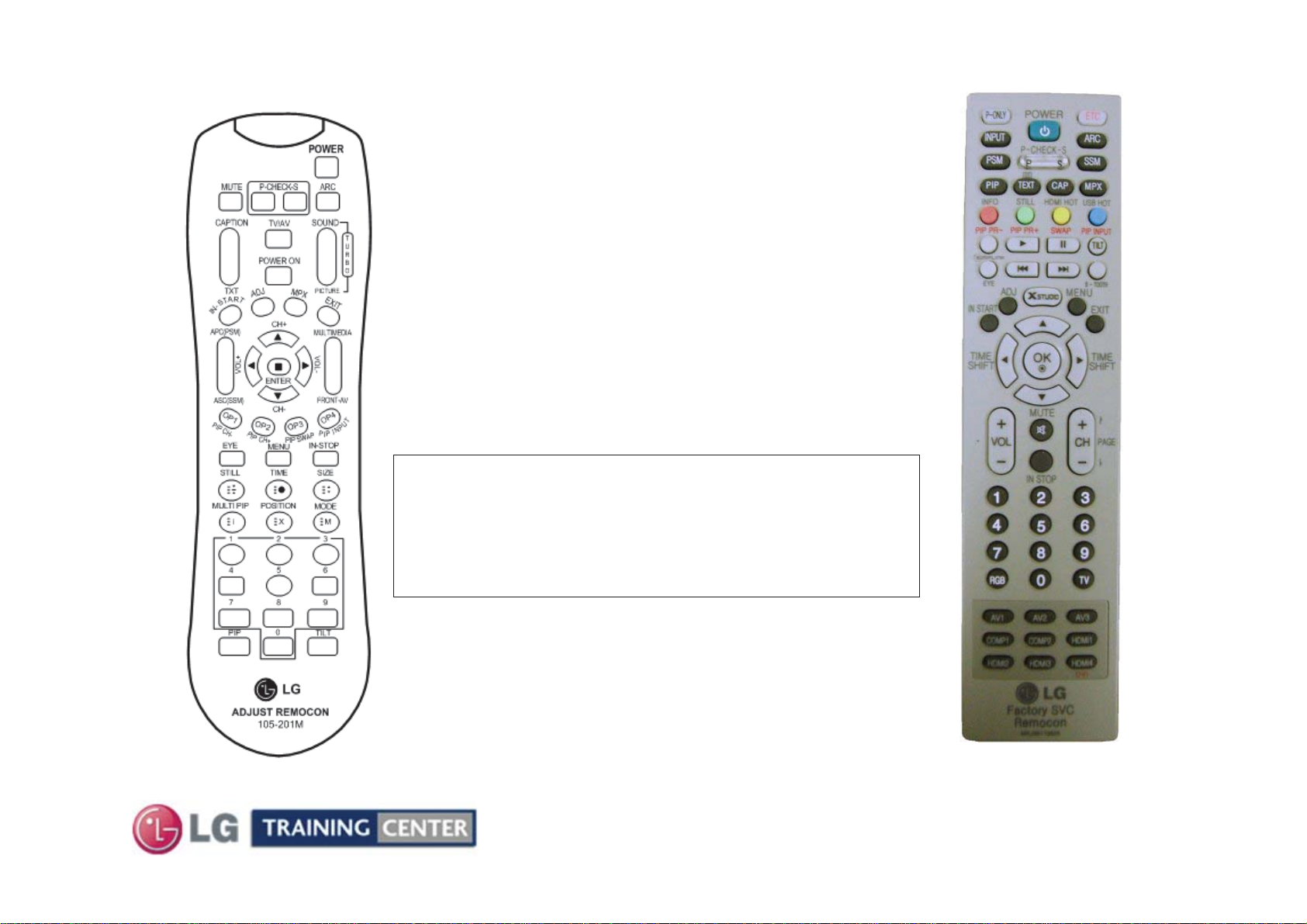
Accessing the Service Menu
Accessing the Service Menu
To access the Service Menu.
1) You must have either Service Remote.
p/n 105-201M or p/n MKJ39170828
2) Press “In-Start”
3) A Password screen appears.
4) Enter the Password.
Note: A Password is required to enter the
Service Menu. Enter; 0000
105-201M
Note: If 0000 does not work use 0413.
18
October 2010 LCD TV 42LE5500
MKJ39170828
Page 19
TV Rear Input / Output Jacks
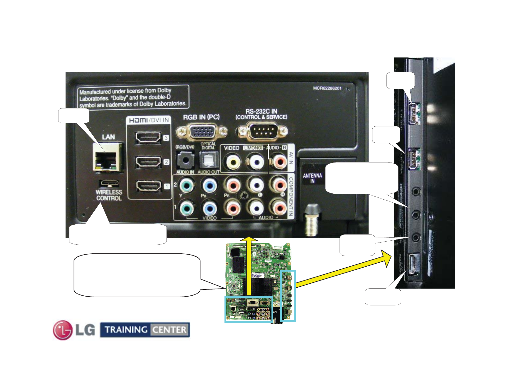
TV Rear Input / Output Jacks
LAN
Rear In/Out Jacks
USB1 or USB2 for Software
Upgrades, Wireless Dungle,
Music and Photos
Component or
Composite
Video/Audio 3
Side In/Out
USB 2
USB 1
Wireless Media Box
Remote Jack
MAIN BOARD
Rear and Side
Input/Output locations
19
Head
Phones
HDMI 4
October 2010 LCD TV 42LE5500
Page 20
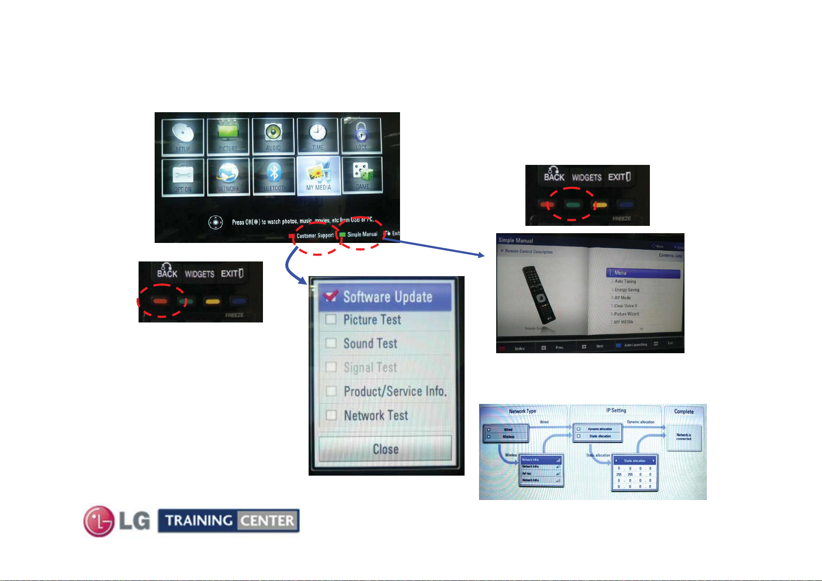
Software Updates (New and Changed Functions)
Software Updates (New and Changed Functions)
A wireless Internet Connection will work for Automatic Software Downloads., however if there are
problems completing download, a Wired Internet Connection is preferred
For network setup assistance, press the
green button for the Simple Manual
Bring up the Customer’s
Menu then Press the Red
button on Remote
With Software Update
Highlighted, Press Select
on Remote
Continue on next page
20
Scroll down to item 9 Network Connections
October 2010 LCD TV 42LE5500
Page 21
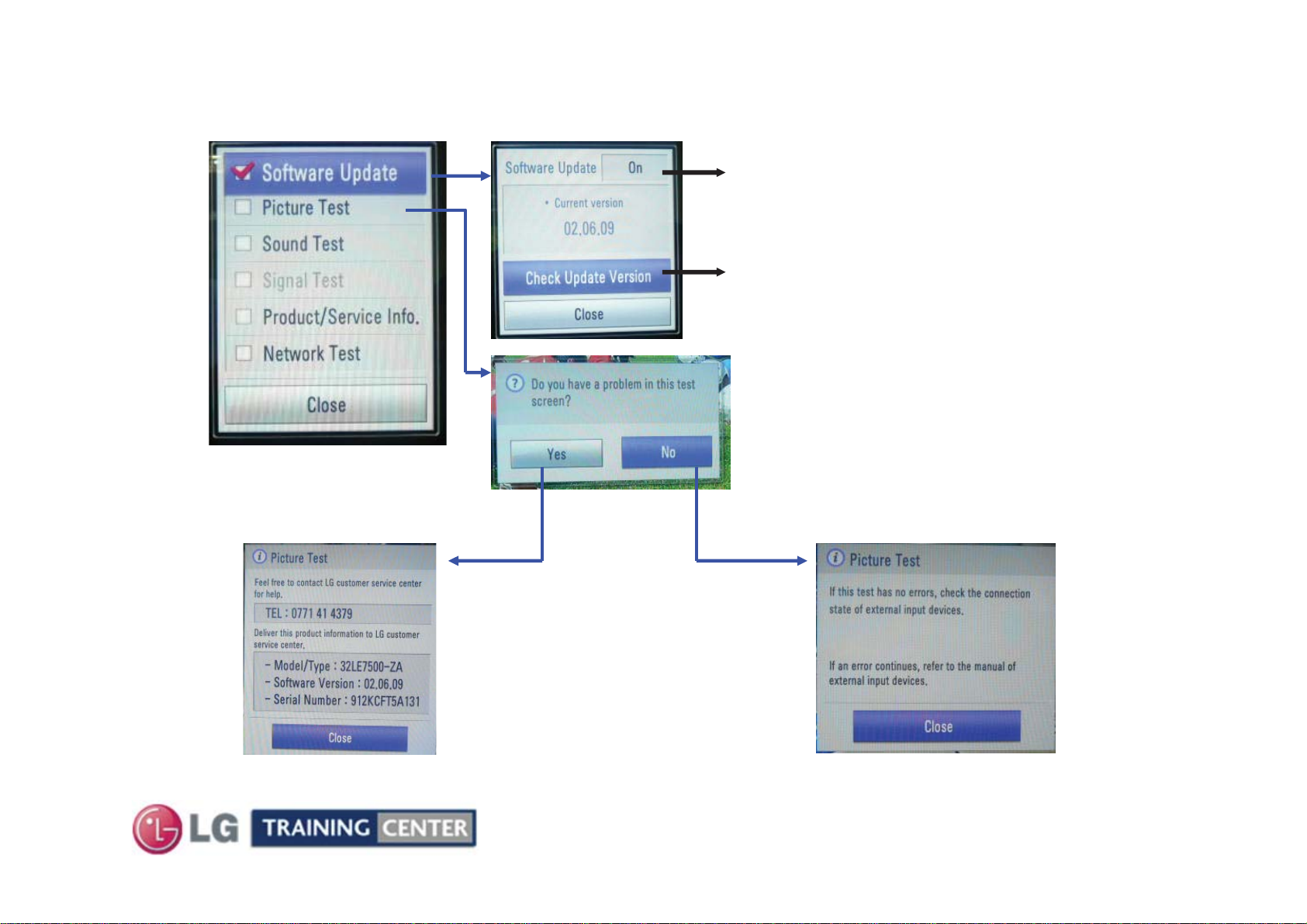
Software Updates (New and Changed Functions) Continued
Software Updates (New and Changed Functions) Continued
Automatic Internet Software Update
- Off : Automatic Software update does not work
- On : if new Software released, Software
Check Update version
- comparison current software version and
Released software version
Additional TV Checks can be made by
Scrolling down.
Picture, Sound and Network Test
After completion of the test, a Pop up menu is
displayed with preloaded back ground picture.
Select NO if everything is OK.
download notice appears at turn on with two
choices, Yes and Remind Me Later.
If you select Yes;
Service call number, Model name,
SW version and serial No. is displayed.
Note: Confirm the “Suffix” of the model
number.
If the Main board is replaced, the Model
and Serial number must be reinserted
into memory. See Model Number D/L.
21
October 2010 LCD TV 42LE5500
Page 22

USB Automatic Software Download Instructions
USB Automatic Software Download Instructions
1) Create an LG_DTV folder on the USB Flash Drive
2) Copy new software (xxx.epk) to "LG_DTV"
folder. Make sure to have correct software file.
3) With TV turned on, insert USB flash drive.
4) You can see the message
“TV Software Upgrade” (See figure to right)
5) Cursor left and highlight "START" Button and
push “Enter” button using the remote control.
6) You can see the download progress Bar.
7) Do not unplug until unit has automatically
restarted.
8) When download is completed, you will see
“COMPLETE”.
9) Your TV will be restarted automatically.
Currently
Installed
Version
Software
Version
found on the
USB Flash
Drive
File found
on the USB
Flash Drive
* CAUTION:
Do not remove AC power or the USB Flash Drive.
Do not turn off Power, during the upgrade
process.
Software Files are now available from
LGTechassist.com
22
October 2010 LCD TV 42LE5500
Page 23

Manual Software Download:
Manual Software Download:
Prepare the Jump Drive as described in the “USB Automatic Download” section and insert it into either of the USB ports.
Bring up the Customer’s Menu and scroll to “OPTIONS”.
Press the “FAV” key 7 times to bring up the Manual Download Screen.
Highlight the Software update file
and press “SELECT” to begin the
download process.
Example of files found
On the Jump Drive
WARNING:
Use extreme Caution
when using the
Manual “Forced”
Download Menu. Any
file can be
downloaded when
selected and may
cause the Main board
to become inoperative
if the incorrect file
was selected.
23
October 2010 LCD TV 42LE5500
Page 24

Service Menu: Downloading EDID Data Pg 1 of 2
Service Menu: Downloading EDID Data Pg 1 of 2
1) Press “ADJ” key. 2) Select menu,
Either “PCM EDID D/L” or AC3 EDID D/L
24
October 2010 LCD TV 42LE5500
Page 25

Service Menu: Downloading EDID Data Pg 2 of 2
Service Menu: Downloading EDID Data Pg 2 of 2
3) Highlight “Start”
then Press “Select” key.
When PCM EDID D/L was selected
When AC3 EDID D/L was selected
4) When Writing appears
Downloading in progress
5) Downloading Complete
Note: When PCM is downloaded, AC3 will be N/G and when AC3 is downloaded PCM will be N/G.
This means that when PCM is OK, PCM audio is priority and when AC3 is OK, AC3 audio is
priority.
25
October 2010 LCD TV 42LE5500
Page 26

42LE5500 Product Dimensions
42LE5500 Product Dimensions
Wattage
Local Dimming TBD
Full White TBD
Stand By 0.1W
24.13/16"
629.92mm
27.3/16"
690.88mm
There must be at least 4 inches of Clearance on all sides
40"
1016mm
17.5/16"
440mm
Model No.
Serial No.
12.3/8"
314.96mm
7.7/8"
200mm
Label
Center
11.5/16"
288mm
5.9/16"
142mm
7.7/8"
200mm
Remove 4 screws to
remove stand for
1.3/16"
30.48mm
wall mount
2.3/8" (60.96mm)
Weight w/o Stand 36.8 lbs
Weight with Stand 43 lbs
20.7/16"
510mm
26
10.5/8"
269.24mm
October 2010 42LE5500 LCD-DV
Page 27

DISASSEMBLY SECTION
DISASSEMBLY SECTION
This section of the manual will discuss Disassembly, Layout
(Circuit Board Identification) of the 42LE5500 LCD Direct View Television.
Upon completion of this section the Technician will have a better
understanding of the disassembly procedures, the layout of the printed
Disassembly:
circuit boards and be able to identify each board.
27
October 2010 LCD TV 42LE5500
Page 28

Removing the Back Cover
Removing the Back Cover
Pay attention to the size and type of screw
The AC Cord
Does Not unplug
Remove plastic
cover.
Remove the 28 screws indicated.
as there are many different types.
Putting in an improper screw when
reassembling may Cause damage.
The Stand has to be removed before removing the back.
28
October 2010 LCD TV 42LE5500
The Stand Bracket has a
plastic cover “Not Shown”
that must be removed to
expose the screws.
Page 29

Circuit Board Layout
Circuit Board Layout
Clips hold the front glass in place, use caution. Add screws while servicing.
Power Supply
(SMPS)
To LEDs
LVDS Cables
Panel Connection
Points
Warning: The Frame has
very sharp edges
Main Board
IR/LED
Board
Soft Touch
Keyboard
Invisible
Speaker Right
LG Logo
Board
29
Invisible
Speaker Left
October 2010 LCD TV 42LE5500
Page 30

42LE5500 Connector Identification Diagram
42LE5500 Connector Identification Diagram
TFT PANEL
p/n: EAJ60871201
To LEDs
If the Panel is replaced, reset the UTTTime.
Service Menu, System 1 Item 12
J3
POWER
SUPPLY
p/n: EAY60803101
p/n: EAY60803201
J2
J1
AC In
P204
P205
P201
SK101
White Plug
Black Plug
To
TFT
Panel
P7501 P7500
n/c
n/c
p/n: EBU60904603
p/n: EBR66101301
p/n: EBU60904602
P8800
P8200
P8000
MAIN
BOARD
IR LED
p/n: EBR64966201
Soft Touch Keys
p/n: EBR64966801
Speaker (Front Right)
p/n: EAB60961501 p/n: EAB60961501
p/n: EAV60793302
30
Speaker (Front Left)
October 2010 42LE5500 LCD-DV
Page 31

Power Supply
Power Supply
Board Removal
Board Removal
Board is “Thin”, be
careful not to flex.
Disconnect
P201, P204,
P205 and AC
In SK101.
p/n EAY60803101
P
2
4
0
P
2
5
0
P
2
0
1
P201
Press in
gently on
the two
tabs
to release
lock
SK101 fits very
snug into it’s
connector.
Remove the 6
screws indicated
by the arrows.
31
AC In
SK101
Press in on the
two tabs
to release lock
October 2010 LCD TV 42LE5500
Page 32

Removing the Main Board
Removing the Main Board
p/n EBU60904603
Flip the locking tab upward, pull the LVDS ribbon out.
Disconnect P7500,
P7501, P8000, P8200 and
P8800
Remove any tape holding
down any cables.
Remove the 7 screws
indicated by the arrows.
Remove decorative
plastic and remove the
board.
NOTE: Always check on
top and behind the Large
ICs. And look for a piece
of Chocolate
(Heat Transfer Material).
Be sure to transfer to
new Board if present.
N/C
N/C
P7501 P7500
P8000
Press in on the
side release
tabs to remove.
Decorative
Metal Plate
After removing the Main, there
are tabs sticking through the
Main board holding the Metal
plate in place.
P8800 P8200
32
October 2010 LCD TV 42LE5500
Page 33

Removing Front IR Board
Removing Front IR Board
Tab
J3
Disconnect J1, J2 and J3 connectors.
Press upward on the two tabs at the top. Tilt the board downward.
Lift straight up To Clear the Tabs at the bottom.
Tab
J2
IR board / Intelligent Sensor
J1
Tab Tab
33
October 2010 LCD TV 42LE5500
p/n EBR64966201
Page 34

TROUBLESHOOTING SECTION
TROUBLESHOOTING SECTION
This section of the manual will discuss troubleshooting.
Upon completion of this section the Technician will have
a better understanding of how to diagnosis and resolve
Troubleshooting:
problems.
34
October 2010 LCD TV 42LE5500
Page 35

POWER SUPPLY SECTION
POWER SUPPLY SECTION
This switch mode power supply develops Stand By 3.5V
at all times when AC is applied.
At power on, it develops 12V and 20V for the Main board.
It develops 120V for the LED Backlights.
This power supply draws less than 1 watt during stand by
mode. The fuse F101 and F103 reads 7.6V
(from hot ground) during this time.
When the controller chip receives the PWR-ON command
3.36V via P201 Pin 1, the primary section increases its
current supplying ability. Both Primary fuses F101 and
F103 now read a little more than 395V.
T102 delivers AC to D206 which develops the 120V for
the LED backlights.
P201 Connector: (To Main Board)
12V (11.43V) is routed out P201 pins 17, 19 and 21 and
20V (21.27V) is routed out P201 pins 2, 3 and 4.
P204 Connector: (To Panel LEDs)
120V is routed out P204 pins 1 and 12.
P205 Connector: (To Panel LEDs)
120V is routed out P205 pins 1 and 12.
35
October 2010 LCD TV 42LE5500
Page 36

Power Supply (SMPS) Board Layout
Power Supply (SMPS) Board Layout
p/n EAY60803101
F101
3.15A/250V
F103
1A/250V
STBY 7.6V
Run 396V
From Hot Gnd
F100
5A/250V
F102
1A/250V
AC Protect
36
Hot Ground
Shock
Hazard
October 2010 LCD TV 42LE5500
Page 37

42LE5500 Power Supply Start Up Sequence
42LE5500 Power Supply Start Up Sequence
AC In
No AC
Det in
this
T510 &
Rectifier
model
P201
At point TV is in
Stand-By state.
Energy Star compliant.
0 .1 Watts
3
P8000
3.5V_ST
2
Other Regs
Reset
Generator
C8108
R8184
Primary side fuses:
Stand-By 7.6V Run 396V (Hot Gnd)
1
BridgeRelays
Stand By
3.5V Reg
5
Stand By
3.5V
RL_ON
2 5 66 8
19~12 16
MAIN
BOARD
Note 1:
5
RL_On
5
5
Power On
Power
2
3
RL_ON
On
Model 1_Opt1 Panel Control
Microprocessor IC8101
5
12V
See
T102
D206
Inverter On
Starts the Inverters
12V/24V
Regulators
24V
17
19
21
IC8801
Audio Amp
12V
8
INV_CTL
Key 1 or IR
POWER SUPPLY (SMPS)POWER SUPPLY (SMPS)
On Board
Inverter
8
9
9
9
Local Dimming (SIN)
V-SYNC
Inv
On
Inverter On
7
4
P-DIM
Globar
9
Dimming
22182~4
IC9302
1.8V_L/
Dimming
P-DIM
Q8004
Panel
VCC
12V
7
9
Processor
7.8V
Video
IC900
IC9102
HVDD
7
IC9301
Dimming
IC9103
DC to
DC
16V, -5V,
9
23
IC
3.3V,
26V,
P8200
P204
8
P205
8
SIN
MOSI, CLK
12 Blocks
7
120V
6
To Panel Backlights
Local and
Global Dimming
Manipulates Backlight
120V
6
Local and
Global Dimming
P-DIM1 (PWM-DIM)
Pulse Width Dimming
Global Dimming
Manipulated by:
Cust Menu for Backlight
Note 1:
12V TURNS ON:
IC8000 5V_USB
IC8003 5V_Normal
IC8005 3.3V_Normal
IC8903 +3.3V_MEMC
IC8902 +1.26V_MEMC
MEMC=
Motion Estimated Motion Compensated
For Video Processor
VCC 3.3V, VDD 16V,
VGL -5V, VGH 26V,
HVDD 7.8V
P7500
P7501
4
Ft IRKey
and
Picture Content
Manipulate P-DIM
7
After Mute Released
LVDS Video
9
And Tru-Motion LVDS Video
LCD PANEL
120Hz
LEDs
Low = Bright
Right Side
Panel
Driver Board
Left Side
Panel
Driver Board
Soft Touch Key
37
Remote or Power Button Key
October 2010 42LE5500 LCD-DV
Page 38

42LE5500 Television Turn On Commands Circuit Drawing
42LE5500 Television Turn On Commands Circuit Drawing
To IC9103 DC to DC
Conv T-CON
SBY3.5V
VSYNC
12V
INV_CTL
12V
12V
PWM-DIM
ERR OUT
PWR
24V
SCLK
SIN
SMPS
P201
1
2
3
4
5
6
7
8
9
10
11
12
13 13
14
15
16 16
17
18
19
20 20
21
22
23 23
24
3.36V
0.02V
11.43V
3.28V
11.43V
0.09V
11.43V
0.38V~3.3V
21.27V
21.27V
21.27V
Gnd
Gnd
Gnd
Gnd
3.5V
3.5V
3.5V
3.5V
Gnd
Gnd
Gnd
3.3V
Gnd
MAIN Board
P8000
1
2
3
4
5
6
7
8
9
10
11
12
14
15
17
18
19
21
22
24
PWM-DIM (PWM Dimming) can vary according to
incoming video IRE level, OSD Backlight setting
and Intelligent Sensor (room light condition).
Range 0.37V to 3.3V.
(Data) 3.25V p/p Data
Panel_Vcc (12V)
+3.3V_Normal
PWR-ON
L8005
PWM-DIM
3.64V
p/p
3.76V p/p
C8024
68uF
+3.5V_ST
L8015
3.36V
+24V
24.6V
L8003
C8001 100uF
L8002
INV_On
VSYNC
SCLK
SIN
Q8004
D
7
IC8005
8
Power_On/Off2_2
Q8002
3.3V
3.36V
C8000
100uF
+12V
11.9V
R8019
100
R8078
R8077 0
0V
R8004
4.7K
3.1V
0
R8076 0
38
S
R8010 10K
11.8V11.79V
G
2
3.36V
6
Q8000
0V
1.8V
11.8V
L8013
R8060
10K
0.66V
R8000
10K
+3.5V_ST
R8184
47K
R8026
1K
Q8005
0V
P-DIM: Digital
Dimming (Variable)
VSYNC / R_VS
M2_SCLK
M2_MOSI
October 2010 42LE5500 LCD-DV
R8011 1.8K
+12V
RL_ON
Reset
C8108
0.1uF
+3.3V_Normal
R8032
10K
R1041 0R8027 0
R9346
22
R9347 22
R8003 22K
Q8003
0.68V
R8176
22K
R8187
22
R8178
22
R8134
22
R9350
22
L8000
Q8001
Power
20
On/Off 2_2
IC8101
Micro
36
RL_ON
Model_Opt_1
Reset
40
Power Det
10
INV_CTL
R25
GPIO 09
IC900
BCM
U5
IC9301
Dimming
R6
T6
0V
IR
Key 1
Key 2
+12V
R8001
47K
R8103
100
16
11
R8135
22
14
25
26
R_VS
M2_SCLK
M2_MOSI
Page 39

Power Supply Board Low Voltage Test 1
Power Supply Board Low Voltage Test 1
AC Should not be applied at any time while adding jumpers or
While unplugging connectors as damage to the circuit Board
may occur.
a) When AC is applied, the SMPS “MUST” be producing
STBY 3.5V on pins 9, 10, 11 or 12 of P201.
If 3.5V Standby is not being generated, the SMPS is defective
and must be replaced. There is no need to continue with the
next test.
But, make sure AC is arriving at the connector SK101.
(b) Unplug P8000 on the Main Board to make insertion of the Jumpers easier.
Use P700 Side to insert resistors
Pin 1 is the
Brown Wire
TEST 1:
(1) Add a jumper between (3.5V STBY) pin 7, 8, 9 or 10 and Pin 1 (PWR_ON). Apply AC.
This will turn on the power supply, relays will click.
a) Check that the 24V and 12V power supplies are turned on,
• P201 (12V pins 17, 19 and 21)
• P201 (24V pins 2, 3 and 4)
• P204 and P205 (120V pins 1 and 12) to the Panel. (Or check D206 + lead)
(2) Remove AC power
No Backlights during this test
39
October 2010 LCD TV 42LE5500
Page 40

Power Supply Board Backlights Test 2
Power Supply Board Backlights Test 2
Continue if the 1sttest was OK.
Leave original jumper in place.
(3) Add another jumper between (STBY_3.5V)
pin 9, 10, 11 or 12 and Pin 18 (INV_On).
(4) Apply AC Power. Simulating a Power and
Backlight On command.
Backlights Normal:
a) If normal, the backlights should turn on.
SMPS OK, Inverter OK.
Backlights Abnormal:
a) Recheck all connections.
b) Confirm the INV On/Off line pulling up to at least 3V.
c) Check the connections to the Panel.
If the Inverter On command is pulling up to 3V and the 120V is being generated
from D206 + lead, See the Inverter Section of the Power Supply for additional checks.
Note: If either P204 or P205 is disconnected, the backlights will come on,
but shut off in 4 seconds.
REMOVE AC POWER:
40
October 2010 LCD TV 42LE5500
Pin 1 is the
Brown Wire
Page 41

42LE5500 Inverter Part of the SMPS
42LE5500 Inverter Part of the SMPS
Gnd
1V (100 IRE)
30V (0 IRE)
Inverter Top Left Connector
1VDD-33 3.5V
2 VLED-RANGE 0V
3Gnd Gnd
4 +12VS 12.44VPin 17-19-21 P201
5Gnd Gnd
6 +3.5VS 3.57VPin 9-12 P201
Inverter Center Left Connector
1 INV_ON 3.28VPin 18 P201
2Gnd Gnd
3Gnd Gnd
4 SCLK 0.09VPin 20 P201
5 FB_STR_VF 1V
6 P-DM1 1.9VPin 22 P201
Inverter Bottom Left Connector
1Error 0VPin 24 P201
2(L-DIM) SIN 3.3VPin 23 P201
3 POWER_ON 3.35VPin 1 P201
4 VSYNC_IN 0VPin 16 P201
5Gnd Gnd
6Gnd Gnd
Pin 23 P201
3.25V p/p
Local Dimming On
100uSec
L-DIM (SIN)
Pin 23 P201
3.25V p/p
Local Dimming Off
100uSec
L-DIM (SIN)
Gnd
INVERTER
Section of the
SMPS
Pin 16 P201
3.64V p/p
V-Sync Signal
Pin 20 P201
B
E
C
B
E
C
B
E
C
B
E
C
B
E
C
B
E
C
B
E
C
B
E
C
B
C
E
B
C
E
B
C
E
B
E
C
P204
120V
n/c
*1V~30V LED Drive
n/c
*1V~30V LED Drive
n/c
120V
P205
120V
n/c
*1V~30V LED Drive
n/c
*1V~30V LED Drive
n/c
120V
*White 100 IRE to Black 0 IRE
These drivers ground the LED blocks. (12 Total). If the
120V is present on Pins 1 and 12 of P204 and P205
you can ground these test points to turn on a block.
LED Drive Signal 50 IRE
3.76V p/p
41
SCLK Signal
32V p/p
10mSec
October 2010 42LE5500 LCD-DV
Page 42

Power Supply Connector P201 Voltage and Diode Check
Power Supply Connector P201 Voltage and Diode Check
P201 Connector “SMPS” to “Main” P8000
Run STBYLabelPin
0.178V11.43V0V12V21
0.178V11.43V0V12V19
0.178V11.43V0V12V17
Diode
Check
*1.45VGndGndERROR24
Open3.3V0VL-DIM (SIN)23
Open0.38V~3.3V0VP-DIM122
Open0.09V0VSCLK20
Open3.28V0VINV-ON18
Open0.02V0VV_SYNC16
GndGndGndGnd13-15
Open3.5V3.57V3.5V9-12
P201 Label
P201 Connector
Odd pins
are on
front row
1
GndGndGndGnd5-8
1.10V21.27V0V24V2-4
1.02V3.36V0VPWR-ON1
*Pin 24 is grounded on the Main Board
Diode Mode values taken with all Connectors Removed
(1) PDIM1 Pin 22 can vary according to incoming video IRE
level, OSD Backlight setting and then Intelligent Sensor
(room light condition) Output from the Video Processor
IC900. Range 0.37V to 3.3V.
.
P-DIM1
3.66V p/p 50IRE
42
October 2010 LCD TV 42LE5500
Page 43

Power Supply Connector P204 / P205 Voltage and Diode Check
Power Supply Connector P204 / P205 Voltage and Diode Check
P204 "SMPS" to “The Panel"
Run STBYLabelPin
(1)
1V~30V0V02-1C10
(1)
1V~30V0V02-2C9
(1)
1V~30V0V02-3C8
(1)
1V~30V0V01-3C5
(1)
1V~30V0V01-2C4
(1)
1V~30V0V02-1C3
Diode
Check
Open120V0V02.A12
Openn/cn/cn/c11
Open
Open
Open
Openn/cn/cn/c7-6
Open
Open
Open
Open0Vn/cn/c2
Open120V0V01.A1
P205 "SMPS" to “The Panel"
Run STBYLabelPin
(1)
1V~30V0V04-1C10
(1)
1V~30V0V04-2C9
(1)
1V~30V0V04-3C8
(1)
1V~30V0V03-3C5
(1)
1V~30V0V03-2C4
(1)
1V~30V0V03-1C3
Diode
Check
Open120V0V04.A12
Openn/cn/cn/c11
Open
Open
Open
Openn/cn/cn/c7-6
Open
Open
Open
Open0Vn/cn/c2
Open120V0V03.A1
P204
1
P205
1
(1)
The drive signal changes due to the brightness level of the
backlights. Low indicates “Bright”. High indicates “Dim”.
Diode Mode values taken with all Connectors Removed
43
October 2010 LCD TV 42LE5500
Page 44

Power Supply Connector SK101 and AC Fuses Voltage and Diode Chec
Power Supply Connector SK101 and AC Fuses Voltage and Diode Chec
k
k
F102
1A/250V
AC
F102
F100
6.3A/250V
AC IN
F100
AC Voltage Readings (From Hot Ground)
Pins 1 and 2 for STBY and RUN.
Diode Mode values taken with all Connectors Removed
LN
SK101 "SMPS" to AC IN
LEL1
120Vac
F100 or F102 (Diode Check)
Main Power Switch Closed
Red or Black Lead on Fuse (Open)
Other Lead on Hot Ground
Diode CheckRun STBYLabelPin
OL
OLNEL3
Bottom Right of SMPS
SK101
44
October 2010 LCD TV 42LE5500
Page 45

Power Supply F101 and F103 Voltage Checks
Power Supply F101 and F103 Voltage Checks
F100
3.15A/250V
F103
1A/250V
From Hot Gnd
From Hot Gnd
STBY 7.6V
STBY 7.6V
Run 396V
Run 396V
If the set was on and then turned off into the Stand-By condition, the voltage
takes a very long time to bleed down to the reading given here.
45
October 2010 LCD TV 42LE5500
Page 46

MAIN BOARD SECTION
MAIN BOARD SECTION
The Main board receives its operational B+ from the Power Supply via P8000.
There are two LVDS cable feeds that are output from the on-board T-CON (TFT Driver) section
directly to the Panel. These carry the duel 12 bit LVDS Video and TruMotion Video equaling a 120Hz
video signal. These signals have already been prepared for the Panel’s Left and Right boards. The
Main board also includes the Tuner, Audio and Audio/Video inputs and selection circuits.
Input Voltages from SMPS.
STAND-BY
RUN
• STBY 3.5V (P8000 pins 9~12)
The Main board also develops several B+ sources on the board.
STAND-BY VOLTAGES
• 3.3V_ST (Voltage direct from SMPS).
LVDS
GENERAL
• 5V_Normal (Made from 12V In).
• 3.3V_Normal (Made from 12V In).
• 5V USB (Made from 12V In).
• Panel_VCC (12V Not generated, but switched
from the 12V arriving from the SMPS).
TUNER and VSB CIRCUIT
• 3.3V_TU (Made from 3.3V_Normal).
• 1.26V_TU (Made from 3.3V_TU).
BCM IC900 Micro/Video Processor
• 3.3V_ST, 1.2V, D1.5V, D1.8V
IC9301 Tru-Motion and Dimming IC
• 1.26V_MEMC, 1.5V_MEMC,
and 3.3V_MEMC
WIRELESS VOLTAGES to JK8700
• 20V (Switched from 20V from SMPS)
AUDIO IC8801
• 1.8V (Made from 3.3V_Normal).
T-CON IC9001
• 3.3V_VCC, -5V_VGL, 27V_VGH,
16V_VDD and HVDD (7.8V)
HDMI VOLTAGES (Q200)
• 1.8V_HDMI (From D1.8V)
• 12V pins 13 and 14
• 20V pins 17 and 18.
46
October 2010 LCD TV 42LE5500
Page 47

Main Board Layout
Main Board Layout
To Panel
P7501
P8000
To SMPS
P7500
See next page for
component
identification
P9000
n/c
P8100
n/c
LAN
IC9301
IC901
IC900
p/n:
EBU60904603
VIDEO
PROCESSOR
IC900, T-CON
IC9001 and
Tru-Motion IC9301
runs Hot.
This is normal.
USB 1
USB 2
Component In
These connectors are
Mini plug type
Headphone
Wireless Remote
P8800
To Speakers
P8200 To Front IR
47
HDMI
October 2010 LCD TV 42LE5500
Page 48

42LE5500 Main Layout
42LE5500 Main Layout
QD
ECB
A1CA2
Tru-Motion
Microprocessor
Videoprocessor
SW9300
Reset
SW8100
Reset
SW1000
Reset
X9300
25Mhz
IC9300
SW9300
X9000
12Mhz
X8100
IC8801
Q8700
P9000
Update
IC8101
Q8800
L8805L8804
P8800
P7501 P7500
IC9301
LG5111
RX/TX
IC9001
T-CON
LG7378A
IC1000
SW8100
SW1000
Micro
IC8804
IC8800
IC8300
Q?
Q8200
Q8201
P8200
IC9100
A
D9101
C
D9102
L9301
IC8900
IC8901
IC900
Video Processor
LGE3549XQ
MAIN BOARD
p/n: EBU60904603
HDMI
Select
L9100
IC9103
A-C
A
A-C
C
IC9302
IC605IC603
L8904
IC9102
L9102
L9101
IC8902
L8012
Q8004
G
Q8003
P9000
Gamma
IC300
Q300
Q8005
D
Q8001
S
Q8008
L8905
IC8202
L8009
IC8000
IC901
54MHz
IC700
TDVJ-H031F
Digital Video
Analog Video
Audio
Tuner Data
Tuner Clock
Tuner B+
P8000
1
2
2
3
Q8007
IC8903
IC8001
L8004
X1001
TU700
18. IF p
17. IF n
16. IF AGC
15. Reset
14. 3.3V
13. 1.26V
12. GND
11. CVBS
10. NC
9. SIF
8. NC
7. SDA
6. SCL
5. NC
4. NC
3. 5V
2. NC
1. NC
IC8005
1
3
L8015
IC8003
L8010
IC301
IC302
USB1
USB2
Component
Composite
HP
HDMI
A1
A2
C
D8310
48
October 2010 42LE5500 LCD-DV
Page 49

42LE5500 Main (Front Side) Component Voltages
IC300 Earphone Amp IC700 (+1.26V_TU) IC8002 (D1.8V) IC8005 (+3.3V_NORMAL) IC8902 (+1.26V_MEMC) IC9102 DC to DC
Pin Pin Regulator Pin Regulator Pin Regulator Pin Regulator Pin HVDD T-CON
[1] 0V [1] 0V (Gnd) [1] 5V [1] 0V (Gnd) [1] 0V (Gnd) [1] 0V (Gnd)
[2] 0V [2] 1.26V (Out) [2] 3.34V (In) [2] 11.8V (In) [2] 11.8V (In) [2] 11.72V (In)
[3] 0V [3] 3.3V (In) [3] 1.8V (Out) [3] 0V (Gnd) [3] 0V (Gnd) [3] 11.72V (In)
[4] 0V [4] Gnd [4] 0.8V [4] 0.8V [4] 3.25V
[5] 0V IC1000 SOC Reset [5] Gnd [5] 0.86V [5] 0.7V [5] 3.2V
[6] 3.3V Pin Generator [6] 0.9V [6] 3.36V (PWR On/Off2 Ctl) [6] 3.36V (PWR On/Off2 Ctl) [6] 0V
[7] 3.3V [1] 3.32V (In) [7] 0.9V [7] 3.36V (Out) [7] 1.3V (Out) [7] 0V
[8] (-1.8V) [2] 0V (Gnd) [8] 1V [8] 3.36V (Out) [8] 1.3V (Out) [8] 11.7V
[9] (-0.8V) [3] 3.3V (Out) [9] 2.38V [9] 0V (Gnd)
[10] Gnd [10] 3.36V (PWR On/Off1 Ctl) IC8007 Power Det Gen IC8903 (+3.3V_MEMC) [10] 1.13V
[11] 0.9V IC8000 5V Regulator Pin (+12V and +3.5V) Pin Regulator [11] 0V (Gnd)
[12] 1.8V Pin for USB IC8003 (+5V_NORMAL) [1] 0V (Gnd) [1] 0V (Gnd) [12] 0V (Gnd)
[13] 3.3V [1] 11.79V (In) Pin Regulator [2] 3.6V (In) [2] 11.8V (In) [13] 0V (Gnd)
[14] 3.3V [2] 5V (Out) [1] 0V (Gnd) [3] 3.5V (Out) [3] 0V (Gnd) [14] 7.7V
[15] Gnd [3] 5V (Out) [2] 11.8V (In) [4] 0.8V [15] 7.7V (HVDD)
[16] 0V [4] 10.5V [3] 0V (Gnd) IC8008 Power Det Gen [5] 0.8V [16] 0V (Gnd)
IC301 Switched [6] 0.8V [5] 0.86V [1] 0V (Gnd) [7] 3.3V (Out) IC9300 Reset for
Pin 5V for USB 2 [7] 4.99V [6] 3.37V (PWR On/Off2 Ctl) [2] 3.6V (In) [8] 3.3V (Out) Pin LG5111
[1] Gnd [8] 0V (Gnd) [7] 5V (In) [3] 3.7V (Out) [1] 3.32V (In)
[2] 5V (In) [8] 5V (In) IC9100 P-GAMMA [2] 0V (Gnd)
[3] 5V IC8001 D1.2V and A1.2V IC8800 (+1.8V_AMP) Pin Chip [3] 3.34V (Out)
[4] 3.3V Pin Regulator IC8004 A2.5V Regulator Pin Regulator [1] 3.3V
[5] 3.3V [1] 0V (Gnd) Pin for USB [1] 0V (Gnd) [2] 0V (Gnd) IC9302 (1.8V_L/Dimming)
[6] 5V (Out) [2] 3.3V [1] n/c [2] 1.8V (Out) [3] 3.3V (In) Pin Regulator
[7] 5V (Out) [3] 0V (Gnd) [2] 3.26V (In) [3] 3.295V (In) [4] 0V (Gnd) [1] 0V (Gnd)
[8] n/c [4] 1.2V [3] 3.26V (In) [5] 6.8V [2] 11.8V (In)
IC302 Switched [6] n/c [5] n/c Pin Regulator [7] 15.3V [4] 0.8V
Pin 5V for USB 1 [7] 4.46V [6] 2.55V (Out) [1] 0V (Gnd) [8] 15.3V [5] 0.76V
[1] Gnd [8] 3.3V [7] 0.8V [2] 1.5V (Out) [9] n/c [6] 3.34V (PWR On/Off2 Ctl)
[2] 5V (In) [9] 3.3V [8] 0V (Gnd) [3] 3.3V (In) [10] 13.47V [7] 1.8V (In)
[3] 5V [10] 3.3V [11] 12.75V [8] 1.8V (In)
[4] 3.3V [11] 1.2V Q8005 INV_ON Q8306 HDMI [12] 11.8V
[5] 3.3V [12] Gnd Pin Driver Pin Det [13] 10V D9101 VGH/VDD
[6] 5V (Out) [13] 3.3V B 0V (INV ON) En B 0V [14] 5.96V Pin Rectifyer
[7] 5V (Out) [14] 0.8V C 3.1V (Out) C 3.3V [15] 4.06V A 15.4V
[8] n/c E Gnd E Gnd [16] 15.3V AC 22.2V
Q300 Earphone Mute Q8003 PANEL_VCC Q8200 IR Buffer Q8307 HDMI [18] 2.96V
Pin L Out Pin
B 0V B 0.679V B 0.02V B 0V [20] 3.3V (In) Pin Rectifyer
C3.3V C0V C3.4V C4.18V A (-5V VGL)
EGnd EGnd EGnd EGnd AC (-1.9V)
Q8001 PANEL_VCC Q8004 PANEL_VCC Q8201 IR Buffer Q8700 Wireless PWR Q8800 AMP_MUTE
Pin
Control 1st Driver Pin Switch Pin 1st Dongle Out Turns on Q8701 Pin Pin 25 IC8801
B 0V S 11.8V (In) B 0V B 0.66V (0.0V Dongle In) B 0V
C 0.68V G 1.8V (Enable) C 3.3V C 0.14V (24V Dongle In) C 3.336V
E Gnd D 11.8V (Out) E Gnd E Gnd E Gnd
[5] 3.3V [4] 0.8V Pin (+24V) [6] 3.36V (PWR On/Off2 Ctl)
[5] 3.3V [4] n/c IC8901 (+1.5V_MEMC) [6] 6.8V [3] 0V (Gnd)
Control 2nd Driver Pin 2nd Pin Det [19] 2.33V D9102 VGL/VCC
[17] 0V C 27.4V (VGH)
C0V
49
October 2010 42LE5500 LCD-DV
Page 50

42LE5500 Main (Back Side) Layout
42LE5500 Main (Back Side) Layout
QD
ECB
A1CA2
Digital Video
Analog Video
Audio
Tuner Data
Tuner Clock
Tuner B+
Q8002
1
3
2
Q8000
TU700
TDVJ-H031F
18. IF p
17. IF n
16. IF AGC
15. Reset
14. 3.3V
13. 1.26V
12. GND
Q702
11. CVBS
10. NC
9. SIF
8. NC
7. SDA
6. SCL
Q701
5. NC
4. NC
3. 5V
2. NC
1. NC
IC602
Q901
Rubber
MAIN BOARD
p/n: EBU60904603
IC606 IC604
IC8200
Rubber
IC8401
Rubber
IC8400
Q8303
Q8305
IC9001
IC9003
D8309
D8306
Q8304
Q200
D
Q8301
D8307
Q8300
Q8302
S
G
Q8701
Q8205
IC9000
IC8100
D8312
Q8308
IC8700
D
GSB
Rubber
50
Q8203
October 2010 42LE5500 LCD-DV
Page 51

42LE5500 Main (Back Side) Component Voltages
)
IC602 D1.8V IC8400 RGB IC8700 Wireless Q200 (1.8V_HDMI) Q8203 IR Wireless Pass
Pin Regulator Pin H/V Sync Pin Buffer Pin Switch Pin 2nd Driver
[1] 0V (Gnd) [1] 1.9V [1] 0V (3.3V Dongle In) S 1.83V (Out) B 0V
[2] 3.29V (PWR On/Off1 Ctl) [2] 1.9V [2] 3.3V (0.3V Dongle In) G 3.35V (PWR On/Off2 Ctl) C 3.3V
[3] 0.9V (DDR_VTT) [3] 4.4V [3] n/c D 1.83V (In) E Gnd
[4] 0.93V [4] 0V [4] n/c
[5] 1.83V [5] 0.9V [5] n/c Q701 Tuner SIF
[6] 3.38V (In) [6] n/c (4.5V) [6] Gnd Pin (Sound) Buffer Q8205 IR Wireless Pass
[7] 1.8V (Out) [7] 0V (Gnd) [7] Gnd B 0.16V Pin 1st Driver
[8] 0.91V (DDR_VTT) [8] n/c (4.5V) [8] Gnd C Gnd B 0.6V
[9] n/c (1.9V) [9] n/c E 0.83V C 0V
IC8100 EEPROM [10] n/c (1.9V) [10] 0.02V EGnd
Pin Micro [11] n/c (4.5V) [11] 0V Q702 Tuner Video
[1] 0V (Gnd) [12] 0.9V [12] 3.3V Pin (Analog) Buffer Q8300, 2 HDMI 2
[2] 0V (Gnd) [13] 0.9V [13] 0V (3.3V Dongle In) B 2.05V Pin Det
[3] 0V (Gnd) [14] 5V [14] 3.3V C 2.75V B 4.2V
[4] 0V (Gnd) [15] 3.3V E Gnd C 0V
[5] 3.37V IC8401 EDID Data [16] 3.3V EGnd
[6] 3.37V Pin PC Q901 FLASH_WP
[7] 0V (Gnd) [1] 0V (Gnd) IC9303 EEPROM Pin for IC901 Q8303, 4, 5 HDMI 3
[8] 3.37V [2] 0V (Gnd) Pin for LG5111 B 0V (Flash_WP) Pin Det
[3] 0V (Gnd) [1] 0V (Gnd) C 3.36V B 0V
IC8200 RS232 [4] 0V (Gnd) [2] 0V (Gnd) E Gnd C 4.2V
Pin Routing [5] 0.7V [3] 0V (Gnd) EGnd
[1] 0V [6] 4.1V [4] 0V (Gnd) Q8000 RL_ON (PWR_On)
[2] 0V [7] 4.5V [5] 3.37V Pin 1st Driver Q8308 CEC Remote
[3] 0V [8] 4.5V (In) [6] 3.37V B 0.66V Pin HDMI CEC
[4] 0V [7] 3.34V C 0V [B] 2.72V
[5] 0V IC9000 Serial Flash [8] 3.37V (In) E Gnd [G] 2.73V
[6] (-5.47V) Pin T-CON [S] 3.27V
[7] n/c (5.59V) [1] 0.06V Q8002 PWR_ON [D] 3.37V
[8] n/c (0V) [2] 0.67V D8306, 7, 9 5V Pull Up Routing Pin Switch
[9] n/c (3.3V) [3] 3.3V (In) Pin HDMI SCL/SDA [1] 3.36V (In) Q8701 IR Wireless Pass
[10] n/c (0.2V) [4] 0V (Gnd) A1 5.04V [2] 0V Pin 2nd Driver
[11] n/c (3.3V) [5] 0V C 4.58V [3] 3.3V (Out) G 24.5V (2.3V Dongle I
[12] 3.35V [6] 0.34V A2 0V S24V
[13] 0V [7] 3.31V (In) D 0V (24.5V Dongle In
[14] (-5.47V) [8] 3.34V (In) D8312 3.5V Pull Up
[15] 0V (Gnd) Pin HDMI CEC
[16] 3.37V A1 0V
C3.26V
A2 3.2V
51
October 2010 42LE5500 LCD-DV
Page 52

Main Board X9001 and X9000 Crystal Checks
Main Board X9001 and X9000 Crystal Checks
IC9301 TruMotion /
Dimming Crystal
3.19V p/p
4.86V p/p
X9001
X9001
25Mhz
1.58V
Runs when
set is On
1.6V
IC9001 T-CON Crystal
3.27V p/p
2.54V p/p
X9000
1.56V
1.6V
12Mhz
Runs when
set is On
X9000
MAIN Board
52
October 2010 LCD TV 42LE5500
Page 53

Main Board X8100 and X1001 Crystal Checks
Main Board X8100 and X1001 Crystal Checks
IC8100 Micro Crystal
Either leg
Either leg
3.13V p/p
2.26V p/p
X8100
10Mhz
Runs all
The time
1.95V
1.52
IC900 BCM Crystal
Either leg
X1001
781mV p/p
789mV p/p
54Mhz
Runs when set is On
1.52V
1.3V
1.85V p/p 2.82V p/p
Runs all
The time
1.75V1.5V
53
MAIN Board
X8100
X8101
X1001
October 2010 LCD TV 42LE5500
Page 54

Main Board DC to DC Converter (Voltages for Panel) Checks
Main Board DC to DC Converter (Voltages for Panel) Checks
Location: Top Center of Board
+27V
VGH
D9101
+16V
VDD
+7.81V
HVDD
IC9103
L9100
IC9102
Panel 12V
L9104
B+ for
IC9102
IC9103
L9102
Panel 12V
L9101
-5V
VGL
D9102
54
+3.3V
VCC
October 2010 LCD TV 42LE5500
Page 55

Main Board Additional Panel Voltage Checks
Main Board Additional Panel Voltage Checks
Location: Top Left of Board
P7500P7501
IC9101
Back Side of Board
From IC9101 Pin 19
-4.7V (VST)
55
From IC9101 Pin 21
-4.8V (VDD-ODD)
From IC9101 Pin 20
-4.8V (VDD-EVEN)
October 2010 LCD TV 42LE5500
Page 56

Main Board Connector P8000 to Power Supply Voltage and Diode Che
Main Board Connector P8000 to Power Supply Voltage and Diode Che
ck
ck
P8000
Odd Pins Front Row
Diode Mode values taken with
all Connectors Removed
P8000 “Main Board" to P201 “SMPS"
Diode CheckRun STBYLabelPin
Open3.36V0VPWR-ON1
Open21.27V0V24V2-4
GndGndGndGnd5-8
1.24V3.5V3.57V3.5V9-12
GndGndGndGnd13-15
1.06V0.02V0VV-SYNC16
Open11.43V0V12V17
1.62V3.28V0VINV-ON18
Open11.43V0V12V19
1.06V0.09V0VSCLK20
Open11.43V0V12V21
Open0.38V~3.3V0VP-DIM22
(1)
PDIM Pin 22 can vary according to incoming video IRE level,
OSD Backlight setting and Intelligent Sensor (room light condition).
Range 0.37V to 3.3V.
56
1.05V3.3V0VL-DIM (SIN)23
GndGndGndERROR24
P-DIM1
3.66V p/p 50IRE
October 2010 LCD TV 42LE5500
Page 57

Main Board Connector P7500 to the Panel Voltage and Diode Check
Main Board Connector P7500 to the Panel Voltage and Diode Check
P7500 Connector “Main" to the “Panel“
RunLabelPin
Diode
Check
GndGndGnd1
Open14.91VGMA12
Open13.5VGMA33
Open12.78VGMA44
Open11.88VGMA65
Open10.02VGMA76
Open8.02VGMA97
Open7.48VGMA108
Open5.99VGMA129
Open4.08VGMA1310
Open2.98VGMA1511
Open2.35VGMA1612
There are no Stand-By Voltages for the Connector
Diode Mode values taken with all Connectors Removed
RunLabelPin
Diode
Check
0.9V1.06VLV0+21
1.09V1.27VLV0-22
0.9V1.4VLV1+23
1.09V1.3VLV1-24
0.9V1.03VLV2+25
1.09V1.3VLV2-26
0.9V1.16VLVCLK+27
1.09V1.17VLVCLK-28
0.9V1.07VLV3+29
1.09V1.27VLV3-30
0.9V1.02VLV4+31
1.09V1.3VLV4-32
RunLabelPin
Diode
Check
Open15.57VVDD41
Open15.57VVDD42
GndGndGnd43
Open6.86VVCOM_IN44
Open6.87VVCOM_FB45
GndGndGnd46
1.5V(-4.7V)VST47
0.6V(-5V)VGL48
1.5V(-4.8V)VDD_EVEN49
1.5V(-4.8V)VDD_ODD50
0.6V(-5V)VGI_P (VGL)51
Open27.4VVGI_N (VGH)52
Open1.06VGMA1813
GndGndGnd14
2.06V1.06VOPT_N15
Gnd1.07VH_CONV16
1.06V0VVST_IN17
1.06V0.62VPOL18
1.06V0.3VSOE19
GndGndGnd20
57
0.9V1.02VLV5+33
1.09V1.3VLV5-34
GndGndGnd35
1.64V3.3VVCC36
1.64V3.3VVCC37
GndGndGnd38
Open7.81VHVDD39
Open7.81VHVDD40
1.5V8VCLK653
1.5V8VCLK554
1.5V8VCLK455
1.5V8VCLK356
1.5V8VCLK257
1.5V8VCLK158
Open7.7VZ_OUT59
GndGndGnd60
October 2010 LCD TV 42LE5500
Page 58

Main Board Connector P7501 to the Panel Voltage and Diode Check
Main Board Connector P7501 to the Panel Voltage and Diode Check
P7501 Connector “Main" to the “Panel“
RunLabelPin
Diode
Check
GndGndGnd1
Open7.7VZ_OUT2
1.5V8VCLK13
1.5V8VCLK24
1.5V8VCLK35
1.5V8VCLK46
1.5V8VCLK57
1.5V8VCLK68
Open27.4VVGH9
0.6V(-5V)VGH10
1.5V(-4.8V)VGH_ODD11
1.5V(-4.8V)VGH_EVEN12
There are no Stand-By Voltages for the Connector
Diode Mode values taken with all Connectors Removed
RunLabelPin
Diode
Check
Open7.81VHVDD21
Open7.81VHVDD22
GndGndGnd23
1.64V3.3VVCC24
1.64V3.3VVCC25
GndGndGnd26
1.09V1.07VRV0+27
0.9V1.12VRV0-28
1.09V1.13VRV1+29
0.9V1.23VRV1-30
1.09V1.13VRV2+31
0.9V1.22VRV2-32
RunLabelPin
Diode
Check
1.06V0.3VSOE42
1.06V0.62VPOL43
1.06V0VVST_IN44
2.06V1.06VOPT_N46
Open1.06VGMA1848
Open2.35VGMA1649
Open2.98VGMA1550
Open4.08VGMA1351
Open5.99VGMA1252
GndGndGnd41
Gnd1.07VH_CONV45
GndGndGnd47
0.6V(-5V)VGL13
1.5V(-4.7V)VST14
GndGndGnd15
Open6.87VVCOM_FB16
Open6.86VVCOM_IN17
GndGndGnd18
Open15.57VVDD19
Open15.57VVDD20
58
1.09V1.17VRVCLK+33
0.9V1.18VRVCLK-34
1.09V1.08VRV3+35
0.9V1.27VRV3-36
1.09V1.12VRV4+37
0.9V1.22VRV4-38
1.09V1.13VRV5+39
0.9V1.22VRV5-40
October 2010 LCD TV 42LE5500
Open7.48VGMA1053
Open8.02VGMA954
Open10.02VGMA755
Open11.88VGMA656
Open12.79VGMA457
Open13.5VGMA358
Open14.91VGMA159
GndGndGnd60
Page 59

Main Board P8200 to (Ft. IR/Intelligent Sensor) Voltage and Diod
Main Board P8200 to (Ft. IR/Intelligent Sensor) Voltage and Diod
e Check
e Check
P8200 Connector "MAIN Board" To P100 "IR Board"
Pin
1
2
3
4
5
6
7
8
9
10
(1)
(1)
SCL
SDA
(2)
IR
Diode CheckRun STBYLabel
P8200
Open3.5V3.56V
Open3.5V3.56V
GndGndGndGnd
1.9V3.3V3.32VKEY 1
1.9V3.3V3.29VKEY 2
1.24V3.47V3.56V3.5V_ST
GndGndGndGnd
Open0V0VLED_LOGO
Open1.6V1.63V
GndGndGndGnd
1
11
12
(1)
Clock pulses only present when Intelligent Sensor is turned on. (3.7V p/p)
(2)
IR pulses (1.6V p/p)
Diode Mode values taken with all Connectors Removed
59
0.52V3.34V0V+3.3V_Normal
Open0V0VLED_R/BUZZ
October 2010 LCD TV 42LE5500
Page 60

Main Board Connector P8800 to Speakers Voltage and Diode Check
Main Board Connector P8800 to Speakers Voltage and Diode Check
Q8800 (Mute) Active Low.
Normal 3.3V Collector to Pin 25
Use speaker out to test for defective Audio Amp IC8801
Note: (Normal, ½ Audio B+)
P8800 CONNECTOR "Main" to "Speakers"
Mute
Pin 25
Q8800
Amp Mute
IC8800
Amp
1.8V
LABEL
SPK-R(-)
SPK-R(+)
SPK-L(-)
SPK-L(+)
Diode CheckRunSBYPin
IC8801
Open10.62V0V1
Open10.62V0V2
Open10.62V0V3
Open10.62V0V4
Audio B+
21.3V
Pins 49-52
(1)
Diode Mode values taken with all Connectors Removed
60
P8800
October 2010 LCD TV 42LE5500
Page 61

Main JK8700 Wireless Media Box Dongle Jack (Voltage and Diode Ch
Main JK8700 Wireless Media Box Dongle Jack (Voltage and Diode Ch
eck)
eck)
JK8700 "MAIN Board" To "Wireless Media Box Dongle"
Diode CheckRun STBYLabelPin
0.98V20.3V0V*20.3V1-6
Wireless Media Box Dongle
must be plugged in for
these voltages.
0.98V0.3V0VDetect7
1.2V3.3V0VInterrupt8
GndGnd0VGnd9
1.1V3.3V0Vn/c10
GndGnd0VGnd11
1.02V3.3V0VI2C_SCL12
1.02V3.3V0VI2C_SDA13
GndGnd0VGnd14
1.17V3.3V0VWireless_RX15
1.22V3.3V0VWireless_TX16
GndGnd0VGnd17
1.37V3.3V0.67VIR18
GndGnd0VGnd19-20
Diode Mode values taken
with all Connectors
JK8700
Jack
1
Removed
Voltages with Wireless Media Box Dongle plugged in. Use Media Box Dongle side to read voltages.
Remove cover, (see Wireless Media Box training manual for details).
*20.3V Switched from Q8701 Drain Back side of the board.
Q8701 turned on by Q8700 front side of the board.
Q8700 turned on by Microprocessor pin 38.
61
October 2010 LCD TV 42LE5500
Page 62

FRONT (IR, INTELLIGENT SENSOR and MOVING LED) SECTION
FRONT (IR, INTELLIGENT SENSOR and MOVING LED) SECTION
The Intelligent Sensor and IR board (located on the bottom left as viewed from the rear) contains the
IR (Infrared Remote Sensor) and the Intelligent Sensor. This board also connects with the Soft Touch
Key Board and the Center LG Logo board. The Center LG Logo lights after power on and the picture
appears. Then dims down in about 2 seconds. At power off, it does the reverse.
The IR board receives it operating B+ via CON1 pin 6 (STBY 3.5V).
The IR (Infrared) remote receiver can be measured (1.57V) at pin 9 of connector CON1 or P8200 on
the Main board in Stand-By. During run pin 9 reads (1.54V).
The IR pulses (1.6V p/p) CON1 pin 9 are sent to P8200 on the Main board and on to the
Microprocessor (IC8101) via pin 16.
The Intelligent Sensor communicates with the Micro/Video Processor IC900 BCM Chip via clock and
data lines SCL1 and SDA1 arriving on connector CON1 from P8200 pins 1 and 2 on the Main board.
The Front Power LEDs are controlled by these same Clock and Data lines which communicate with
the LED Driver IC U1 on the Soft Touch Key board.
The Key board is routed to the IR board via CON2 and output on CON1 Key 1 and Key 2 lines,
(Key 1 pin 4 and Key 2 pin 5). Arriving at P8200 pins 4 and 5 on the Main Board.
Then to the Microprocessor 25 and 26 lines.
62
October 2010 LCD TV 42LE5500
Page 63

Front IR Board (Connections Identified)
Front IR Board (Connections Identified)
(1)
J3
To Center
Logo Board
p/n EBR64966201
J2
To Soft Touch
Key Board
IR and Intelligent
Sensor board
63
J1
To Main Board
October 2010 LCD TV 42LE5500
Page 64

Front Board Connectors CON1, CON2 and CON3 Voltage and Diode Ch
Front Board Connectors CON1, CON2 and CON3 Voltage and Diode Ch
eck
eck
CON1 "Front IR" to P8200 " MAIN"
Run STBYLabelPin
(1)
SCL1
(1)
SDA2
(2)
IR9
Diode
Check
Open3.5V3.56V
Open3.5V3.56V
GndGndGndGnd3
1.9V3.3V3.32VKEY 14
1.9V3.3V3.29VKEY 25
1.24V3.47V3.56V3.5V_ST6
GndGndGndGnd7
Open0V0VLED_LOGO8
Open1.6V1.63V
GndGndGndGnd10
CON2 "Front IR" to “Soft Touch Key Board"
Diode CheckRun STBYPin
Open3.47V3.56V1
Open1.63V0V2
GndGndGnd3
Open3.5V3.56V4
Open3.5V3.56V5
GndGndGnd6
1.9V3.3V3.32V7
1.9V3.3V3.29V8
CON3 "Front IR" to “LG Logo Board"
(1)
Clock pulses only present when Intelligent Sensor is
turned on. (3.7V p/p)
(2)
IR pulses (1.6V p/p)
Diode Mode values taken with all Connectors Removed
0.52V3.34V0V+3.3V_Normal11
Open0V0VLED_R/BUZZ12
64
October 2010 LCD TV 42LE5500
Diode CheckRun STBYPin
1.24V3.47V3.56V1
GndGndGnd2
Open0.6V1.36V3
GndGndGnd4
Page 65

INVISIBLE SPEAKER SECTION
INVISIBLE SPEAKER SECTION
Speaker
The 42LE5500 contains the Invisible Speaker system.
The Full Range Speakers point downward, so there is no front viewable speaker grill or air ports.
Installed
Top View
p/n EAB60961501
Side View
Front View
65
October 2010 LCD TV 42LE5500
Page 66

INTERCONNECT DIAGRAM (11 X 17 FOLDOUT SECTION)
INTERCONNECT DIAGRAM (11 X 17 FOLDOUT SECTION)
This section shows the 11X17 foldout that
This section shows the 11X17 foldout that’’
s available in the Paper
s available in the Paper
and Adobe version of the Training Manual.
and Adobe version of the Tr
aining Manual.
The Adobe version of this Training Manual allows the viewer to
The Adobe version of thi
s Training Manual allows the viewer to
zoom in and out making reading of the small text easier.
zoom i
n and out making reading of the small text easier.
This Power Point shows a graphical representation o
f the 11 X 17
This Power Point shows a graphical representation of the 11 X 17
foldout page so clarity
is limited.
foldout page so clarity is limited.
66
October 2010 LCD TV 42LE5500
Page 67

P204 "SMPS" To “The Panel"
Pin Label STBY Run Diode Check
12 02.A 0V 117.8V Open
11 n/c n/c n/c Open
10 02-1C 0V 1V~30V Open
9 02-2C 0V 1V~30V Open
8 02-3C 0V 1V~30V Open
7-6 n/c n/c n/c Open
5 01-3C 0V 1V~30V Open
4 01-2C 0V 1V~30V Open
3 02-1C 0V 1V~30V Open
2 n/c n/c 0V Open
1 01.A 0V 117.8V Open
SMPS BOARD
p/n: EAY60803101
Components
Inside
Dashed Line
are Hot Ground
16uF/450V
F101-F103
Hot Gnd
Stby 7.6V
Q602
E
Run 396V
B
C
Indicates Hot
Ground
Front pins on connector
are odd numbers.
P201
P201
Front pins on connector
are odd numbers.
SMPS TEST 1
SMPS TEST 2
21uF/450V
21uF/450V
21uF/450V
21uF/450V
L601
D601
BD101
STBY 3.5V
12V
12V
STBY 3.5V
12V12V
STBY 3.5V
INV-ON
B
STBY 3.5V
12V12V
P205 "SMPS" To “The Panel"
Pin Label STBY Run Diode Check
12 04.A 0V 120V Open
11 n/c n/c n/c Open
10 04-1C 0V 1V~30V Open
9 04-2C 0V 1V~30V Open
8 04-3C 0V 1V~30V Open
7-6 n/c n/c n/c Open
5 03-3C 0V 1V~30V Open
4 03-2C 0V 1V~30V Open
3 03-1C 0V 1V~30V Open
2n/c n/c 0V Open
1 03.A 0V 120V Open
B
IC104
IC105
CE
Q207
T102
Inverter
D206
T101
F101
21uF/450V
3.15A
21uF/450V
250V
F103
250V
1A
L602
D601 Q602
+
-
RL101
RL102
R149
R149
SMPS TEST 1: To Force
Power Supply On.
Disconnect P8000 on Main
board.
24V24V
(A) Jump pins 9, 10, 11 or 12
4 28 612 1016 1420 18222324
(3.5V) to pin 1. (Test Voltage
3 17 511 915 1319 1721
Outputs 12V, 24V to Main and
24V
PWR ON
24V to both Inverters). Remove
A
AC power.
Leave the jumper in place.
SMPS TEST 2: (B) Jump pins
9, 10, 11 or 12 (3.5V) to pin 18
(INV-ON). Apply AC power, the
Backlights should turn on.
24V24V
Note; If there is a problem with
4 28 612 1016 1420 18222324
a load on the Inverter you can
3 17 511 915 1319 1721
Remove AC and Disconnect
24V
PWR ON
P205 or P204. When AC is
A
reapplied, the Backlight LEDs
should turn on for about 6
seconds and then shut off.
Q203
-
LED
Power
+
120V
D204
D203
D202
D201
T501
IC501
16uF/450V
F102
SK101
AC In
Note: If a particular area is exhibiting a dimmer
backlight level than other areas or the overall
brightness seems dim, be sure to first check the
customer’s Menu setting for Backlights. Raise the
percentage and see if the overall brightness returns
to normal. If not,
st
1
: Check the P-DIM level, it should rise with the
percentage shown on screen. 100%, 3.3V. Follow
the P-DIM signal all the way to the Inverter.
nd
2
: Turn off Local Dimming in the Customers
Menu. If the brightness returns to normal, examine
the signals required for Local Dimming.
(SIN, V-SYNC and SCLK).
See the Inverter Section
Blow Up on the Right
P204
To the Panel
P205
C
E
B
250V
P201
1A
P201 "SMPS" To P8000 "MAIN Board"
Pin Label STBY Run
24 ERROR 0V 0V 1.45V
23 L-DIM (SIN) 0V 3.3V Open
22 P-DIM 0V 0.38V~3.3V Open
21 12V 0V 11.43V 0.178V
20 SCLK 0V 0.09V Open
19 12V 0V 11.43V 0.178V
18 INV-ON 0V 3.28V Open
IC502
IC503
Q511
17 12V 0V 11.43V 0.178V
16 V-SYNC 0V 0.02V Open
13-15 Gnd Gnd Gnd Gnd
E
C
B
9-12 3.5V 3.57V 3.5V Open
5-8 Gnd Gnd Gnd Gnd
2-4 24V 0V 21.27V 1.10V
F100
1 PWR-ON 0V 3.36V 1.02V
5A
(1)
250V
PDIM Pin 22 can vary according to incoming video IRE level,
OSD Backlight setting and then Intelligent Sensor (room light
condition) Output from the Video Processor IC900.
Range 0.37V to 3.3V.
J3
IR Receiver
Intelligent
Sensor
LG Logo
42LE5500 INTERCONNECT DIAGRAM
You can also these each of the 12
blocks functionality by grounding the
driver output signals. See “Forcing on
a Block of LEDs on the right.
J3 "IR Board" To
"Center Logo Board"
J2
Pin STBY Run Diode
Front IR
Front “Soft Switch” Keys
1 3.45V 3.0V 1.5V
2 Gnd Gnd Gnd
3 1.36V 0.64V Open
4
J1
J2 "IR Board" To "Soft Touch Key Board"
Pin STBY Run Diode
Gnd Gnd Gnd
1 3.45V 3.36V Open
2 0V 1.63V Open
3 Gnd Gnd Gnd
4 3.3V 3.3V Open
Diode Check
P8000
Diode
Gnd
1.05V
Open
Open
1.06V
Open
1.62V
Open
1.06V
Gnd
1.24V
Open
Open
Open
Pin STBY Run Diode
5 3.28V 3.28V Open
6 Gnd Gnd Gnd
7 3.45V 3.36V Open
8 3.45V 3.36V Open
1 VDD-33 3.5V
2 VLED-RANGE 0V
3Gnd Gnd
4 +12VS 12.44VPin 17-19-21 P201
5Gnd Gnd
6+3.5VS3.57VPin 9-12 P201
1 INV_ON 3.28VPin 18 P201
2Gnd Gnd
3Gnd Gnd
4 SCLK 0.09VPin 20 P201
5 FB_STR_VF 1V
6 P-DM1 1.9VPin 22 P201
1 Error 0VPin 24 P201
2(L-DIM) SIN 3.3VPin 23 P201
3 POWER_ON 3.35VPin 1 P201
4 VSYNC_IN 0VPin 16 P201
5Gnd Gnd
6Gnd Gnd
S-CLK Pin 23 P201
3.25V p/p
Local Dimming On
S-CLK Pin 23 P201
3.25V p/p
Local Dimming Off
SCLK Pin 20 P201
3.76V p/p
V-SYNC Pin 16 P201
3.64V p/p
P8800 "Main" To "Speakers"
Label
Pin SBY Run
1 SPK-R(-) 0V 12.3V Open
2 SPK-R(+) 0V 12.3V Open
3 SPK-L(-) 0V 12.3V Open
4 SPK-L(+) 0V 12.3V Open
Intelligent Sensor
Intelligent Sensor
Stand-by
The Panel contains 12 LED Blocks
To force a Block to turn on, simple ground
the pin providing the 13V source is present.
INVERTER SECTION
OF THE SMPS
Gnd
Forcing on
A Block of LEDs.
SW9300
These drivers ground the LED blocks. (12 Total). If the 120V is present on Pins 1 and
X9300
25Mhz
IC9300
Tru-
SW9300
Motion
Reset
IC9000
X9000
12Mhz
n/c
P9000
Micro
Reset
Video
Reset
IC8100
X8100
Q8308
Micro
Q8800
SW8100
SW1000
IC8801
Diode
To Speakers
P8200 "MAIN Board" To J1 "IR Board"
Pin Label STBY Run
1 SCL 3.56V 3.5V Open
2 SDA 3.56V 3.5V Open
3 Gnd Gnd Gnd Gnd
4 Key1 3.32V 3.3V 1.9V
5 Key2 3.29V 3.3V 1.9V
6 3.5V_ST 3.56V 3.47V 1.24V
Q8700
IC8700
P8800
Diode Check
1V (100 IRE)
Gnd
30V (0 IRE)
B
E
B
E
B
E
B
E
B
E
B
E
B
E
B
E
B
E
B
E
B
E
B
E
C
C
C
C
C
C
C
C
C
C
C
C
P204
P205
*White 100 IRE to Black 0 IRE
12 of P204 and P205 you can ground these test points to turn on a block.
To the Panel
P7501 P7500
IC9001
IC9301
IC9003
LG5111
IC9001
T-CON
IC8900
SW8100
IC1000
SW1000
IC8804
IC8300
D
HDMI
Select
Q8304
IC8400
D8307
Q8303
Q8300
D8309
Q8302
Q8200
Q8305
D8306
P8200
Pin Label STBY Run
7GndGndGndGnd
8LED_LOGO
9 IR 1.63V Open
10 Gnd Gnd Gnd
3.3V_Normal
11
12 LED_BUZZ 0V Open
D8312
IC8101
L8805L8804
Q8701
Q8205
X8101
D
GSB
IC8800
LAN
Q?
LGE7378A
32.768Khz
Q200
S
G
Q8301
Q8201
Q8203
IC9100
L9100
IC9103
A
A-C
D9101
C
A
A-C
D9102
C
IC9302
L9301
IC8901
L8904
IC604
IC605IC603
IC606
IC900
Video Processor
LGE3549XQ
MAIN BOARD
p/n: EBU60904603
IC8200
IC8401
0V
0V Open
1.6V
Gnd
0V 0.59V
3.34V
0V
IC9102
L9102
Q8003
L9101
IC8902
L8012
IC602
Diode Check
To The Panel
120V
n/c
*1V~30V LED Drive
n/c
*1V~30V LED Drive
n/c
120V
120V
n/c
*1V~30V LED Drive
n/c
*1V~30V LED Drive
n/c
120V
P8000
Q8005
Q8000
Q8004
D
Q8001
G
S
2
Q8008
Q8007
IC8903
L8905
IC8202
L8009
P9000
Gamma
IC8000
Q901
L8004
IC901
54MHz
IC700
IC300
Q300
TDVJ-H031F
Digital Video
Q702
Q701
Tuner Data
Tuner Clock
Tuner B+
1
2
3
X1001
TU700
18. IF p
17. IF n
16. IF AGC
15. Reset
14. 3.3V
13. 1.26V
12. GND
11. CVBS
10. NC
9. SIF
8. NC
7. SDA
6. SCL
5. NC
4. NC
3. 5V
2. NC
1. NC
1
2
Q8002
1
3
IC8001
3
IC8003
IC302
IC8005
L8015
L8010
Component
Composite
Analog
Audio
HDMI
D8310
32V p/p 120Hz
32V p/p 120Hz
Drive Signals
to LED Blocks
IC301
USB1
USB2
HP
A1
A2
C
80 IRE
5 IRE
Page 68

42LE5500 MAIN (FRONT SIDE) SIMICONDUCTORS
IC700 (+1.26V_TU) IC8002 (D1.8V) IC8005 (+3.3V_NORMAL) IC8902 (+1.26V_MEMC) IC9102 DC to DC Q8003 PANEL_VCC Q8700 Wireless PWR
Pin Regulator Pin Regulator Pin Regulator Pin Regulator Pin HVDD T-CON Pin
[1] 0V (Gnd) [1] 5V [1] 0V (Gnd) [1] 0V (Gnd) [1] 0V (Gnd) B 0.679V B 0.66V
[2] 1.26V (Out) [2] 3.34V (In) [2] 11.8V (In) [2] 11.8V (In) [2] 11.72V (In) C 0V C 0.14V
[3] 3.3V (In) [3] 1.8V (Out) [3] 0V (Gnd) [3] 0V (Gnd) [3] 11.72V (In) E Gnd E Gnd
IC1000 SOC Reset [5] Gnd [5] 0.86V [5] 0.7V [5] 3.2V Q8004 PANEL_VCC Q8700 Wireless PWR
Pin Generator [6] 0.9V [6] 3.36V (PWR On/Off2 Ctl) [6] 3.36V (PWR On/Off2 Ctl) [6] 0V Pin Switch Dongle In Turns on Q8701
[1] 3.32V (In) [7] 0.9V [7] 3.36V (Out) [7] 1.3V (Out) [7] 0V S 11.8V (In) B 0.0V
[2] 0V (Gnd) [8] 1V [8] 3.36V (Out) [8] 1.3V (Out) [8] 11.7V G 1.8V (Enable) C 24V
[3] 3.3V (Out) [9] 2.38V [9] 0V (Gnd) D 11.8V (Out) E Gnd
IC8000 5V Regulator Pin (+12V and +3.5V) Pin Regulator [11] 0V (Gnd) Q8005 INV_ON Q8800 AMP_MUTE
Pin for USB IC8003 (+5V_NORMAL) [1] 0V (Gnd) [1] 0V (Gnd) [12] 0V (Gnd) Pin Driver Pin Pin 25 IC8801
[1] 11.79V (In) Pin Regulator [2] 3.6V (In) [2] 11.8V (In) [13] 0V (Gnd) B 0V (INV ON) En B 0V
[2] 5V (Out) [1] 0V (Gnd) [3] 3.5V (Out) [3] 0V (Gnd) [14] 7.7V C 3.1V (Out) C 3.336V
[3] 5V (Out) [2] 11.8V (In) [4] 0.8V [15] 7.7V (HVDD) E Gnd E Gnd
[4] 10.5V [3] 0V (Gnd) IC8008 Power Det Gen [5] 0.8V [16] 0V (Gnd)
[5] 3.3V [4] 0.8V Pin (+24V) [6] 3.36V (PWR On/Off2 Ctl) Q8200 IR Buffer D9101 VGH/VDD
[6] 0.8V [5] 0.86V [1] 0V (Gnd) [7] 3.3V (Out) IC9300 Reset for Pin 2nd Pin Rectifyer
[7] 4.99V [6] 3.37V (PWR On/Off2 Ctl) [2] 3.6V (In) [8] 3.3V (Out) Pin LG5111 B 0.02V A 15.4V
[8] 0V (Gnd) [7] 5V (In) [3] 3.7V (Out) [1] 3.32V (In) C 3.4V AC 22.2V
IC8001 D1.2V and A1.2V IC8800 (+1.8V_AMP) Pin Chip [3] 3.34V (Out)
Pin Regulator IC8004 A2.5V Regulator Pin Regulator [1] 3.3V Q8201 IR Buffer D9102 VGL/VCC
[1] 0V (Gnd) Pin for USB [1] 0V (Gnd) [2] 0V (Gnd) IC9302 (1.8V_L/Dimming) Pin 1st Pin Rectifyer
[2] 3.3V [1] n/c [2] 1.8V (Out) [3] 3.3V (In) Pin Regulator B 0V A (-5V VGL)
[3] 0V (Gnd) [2] 3.26V (In) [3] 3.295V (In) [4] 0V (Gnd) [1] 0V (Gnd) C 3.3V AC (-1.9V)
[4] 1.2V [3] 3.26V (In) [5] 6.8V [2] 11.8V (In) E Gnd C 0V
[5] 3.3V [4] n/c IC8901 (+1.5V_MEMC) [6] 6.8V [3] 0V (Gnd)
[6] n/c [5] n/c Pin Regulator [7] 15.3V [4] 0.8V Q8306 HDMI
[7] 4.46V [6] 2.55V (Out) [1] 0V (Gnd) [8] 15.3V [5] 0.76V Pin Det
[8] 3.3V [7] 0.8V [2] 1.5V (Out) [9] n/c [6] 3.34V (PWR On/Off2 Ctl) B 0V
[9] 3.3V [8] 0V (Gnd) [3] 3.3V (In) [10] 13.47V [7] 1.8V (In) C 3.3V
[10] 3.3V [11] 12.75V [8] 1.8V (In) E Gnd
[11] 1.2V [12] 11.8V
[12] Gnd [13] 10V Q8001 PANEL_VCC Q8307 HDMI
[13] 3.3V [14] 5.96V Pin Control 1st Driver Pin Det
[14] 0.8V [15] 4.06V B 0V B 0V
[4] Gnd [4] 0.8V [4] 0.8V [4] 3.25V
[10] 3.36V (PWR On/Off1 Ctl) IC8007 Power Det Gen IC8903 (+3.3V_MEMC) [10] 1.13V
[8] 5V (In) IC9100 P-GAMMA [2] 0V (Gnd) E Gnd C 27.4V (VGH)
[16] 15.3V C 0.68V C 4.18V
[17] 0V E Gnd E Gnd
[18] 2.96V
[19] 2.33V
[20] 3.3V (In)
Control 2nd Driver Dongle Out Turns on Q8701
42LE5500 MAIN (BACK SIDE) SIMICONDUCTORS
IC602 D1.8V IC8200 RS232 IC8401 EDID Data IC9303 EEPROM Q8000 RL_ON (PWR_On) Q8303, 4, 5 HDMI 3
Pin Regulator Pin Routing Pin PC Pin for LG5111 Pin 1st Driver Pin Det
[1] 0V (Gnd) [1] 0V [1] 0V (Gnd) [1] 0V (Gnd) B 0.66V B 0V
[2] 3.29V (PWR On/Off1 Ctl) [2] 0V [2] 0V (Gnd) [2] 0V (Gnd) C 0V C 4.2V
[3] 0.9V (DDR_VTT) [3] 0V [3] 0V (Gnd) [3] 0V (Gnd) E Gnd E Gnd
[4] 0.93V [4] 0V [4] 0V (Gnd) [4] 0V (Gnd)
[5] 1.83V [5] 0V [5] 0.7V [5] 3.37V Q8002 PWR_ON Q8308 CEC Remote
[6] 3.38V (In) [6] (-5.47V) [6] 4.1V [6] 3.37V Pin Switch Pin HDMI CEC
[7] 1.8V (Out) [7] n/c (5.59V) [7] 4.5V [7] 3.34V [1] 3.36V (In) [B] 2.72V
[8] 0.91V (DDR_VTT) [8] n/c (0V) [8] 4.5V (In) [8] 3.37V (In) [2] 0V [G] 2.73V
IC8100 EEPROM [10] n/c (0.2V) IC8700 Wireless Q200 (1.8V_HDMI) [D] 3.37V
Pin Micro [11] n/c (3.3V) Pin Buffer Pin Switch Q8203 IR Wireless Pass D8312 3.5V Pull Up
[1] 0V (Gnd) [12] 3.35V [1] 0V (3.3V Dongle In) S 1.83V (Out) Pin 2nd Driver Pin HDMI CEC
[2] 0V (Gnd) [13] 0V [2] 3.3V (0.3V Dongle In) G 3.35V (PWR On/Off2 Ctl) B 0V A1 0V
[3] 0V (Gnd) [14] (-5.47V) [3] n/c D 1.83V (In) C 3.3V C 3.26V
[4] 0V (Gnd) [15] 0V (Gnd) [4] n/c E Gnd A2 3.2V
[5] 3.37V [16] 3.37V [5] n/c Q701 Tuner SIF
[6] 3.37V [6] Gnd Pin (Sound) Buffer D8306, 7, 9 5V Pull Up Routing
[7] 0V (Gnd) IC8400 RGB [7] Gnd B 0.16V Q8205 IR Wireless Pass Pin HDMI SCL/SDA
[8] 3.37V Pin H/V Sync [8] Gnd C Gnd Pin 1st Driver A1 5.04V
[9] n/c (3.3V)
[1] 1.9V [9] n/c E 0.83V B 0.6V C 4.58V
[2] 1.9V [10] 0.02V C0V A20V
[3] 4.4V [11] 0V Q702 Tuner Video E Gnd
[4] 0V [12] 3.3V Pin (Analog) Buffer
[5] 0.9V [13] 0V (3.3V Dongle In) B 2.05V Q8300, 2 HDMI 2
[6] n/c (4.5V) [14] 3.3V C 2.75V Pin Det
[7] 0V (Gnd) [15] 3.3V E Gnd B 4.2V
[8] n/c (4.5V) [16] 3.3V C0V
[9] n/c (1.9V) Q901 FLASH_WP E Gnd
[10] n/c (1.9V) IC9000 Serial Flash Pin for IC901
[11] n/c (4.5V) Pin T-CON B 0V (Flash_WP)
[12] 0.9V [1] 0.06V C 3.36V
[13] 0.9V [2] 0.67V E Gnd
[14] 5V [3] 3.3V (In)
[4] 0V (Gnd)
[5] 0V
[6] 0.34V
[7] 3.31V (In)
[8] 3.34V (In)
[3] 3.3V (Out) [S] 3.27V
Page 69

42LE5500
42LE5500
Conclusion
Conclusion
Page
Page
Direct View LCD
Direct View LCD
This concludes the
42LE5500
training session.
 Loading...