

Page 1
LCD TV
Please read Information Manual included together
before reading this manual and operating your set.
Retain it for future reference.
Record model number and serial number of the set.
See the label attached on the back cover and quote
this information to your dealer when you require service.
P/NO : 38289U0023B(0512-REV00)
Printed in Korea
OWNER’S MANUAL
MODEL: 32LB1R**37LB1R
**
42LB1R
**
Page 2

2
Owner’s Manual
1.5V
1.5V
Power Cord
Q.VIEW
1 2 3
4 5 6
8
0
9
S
M
S
L
E
E
P
I/II
ARC
O
K
O
DE
H
O
LD
P
I
P
P
R
-
PIP P
R
+
S
W
AP
PIP
INP
UT
VOL
PR
M
U
T
E
LIST
EXIT
TV
F
A
V
O
U
R
IT
E
Q.VIEW
P
OW
ER
1 2 3
4 5 6
78
0
9
A
UD
IO
TE
X
T
PIP
CABLE
Z
O
O
M
-
ZOOM
+
P
S
M
SSM
S
T
B
S
L
E
E
P
I/II
M
ENU
ARC
V
C
R
D
V
D
M
O
D
E
O
K
PO
S
IT
IO
N
TIM
E
R
E
VEA
L
?
MO
D
E
M
M
IX
S
IZ
E
H
OLD
IN
DE
X
i
IN
P
U
T
TV
P
I
P
P
R
-
P
IP P
R+
S
W
AP
PIP INP
U
T
VOL
PR
M
U
T
E
LIST
EXIT
Remote Control / Batteries
Ensure that the following accessories are included with your TV. If any accessory is missing, please contact the
dealer from where you purchased the product.
Accessories
Audio cable (PC)
Twister Holder
Polishing Cloth
Polish the screen with the cloth.
D-SUB cable (PC)
2-TV Brackets, 2-Wall Bracket2-TV Bracket Bolts
Cable Management
Page 3
3
ENGLISH
Contents
Contents
Introduction
Operation
2 Accessories
5 Controls
5 Swivel stand
6 Connection Options
8 Remote Control Key Functions
Setting up
TV stations
Basic operation
Installation
11 Basic Connection
13 External Equipment Connections
13 Antenna Connection
13 Headphone Socket
14 VCR Setup
16 DVD Setup
17 External Stereo
18 STB ( Set-Top Box) Setup
19 Cable TV Setup
20 External AV Source Setup
21 PC Setup
22 Supported display resolution
22 Power Cord Connection
23 Turning On/Off the TV
23 Volume Adjustment
23 Programme selection
23
On screen language selection
24 How to adjust the OSD screen
25 Auto programme tuning
26 Manual programme tuning
27 Fine tuning
27 Assigning a station name
29 Programme edit
30
Favourite programme
30
Calling the programme table
31
PSM (Picture Status Memory)
31 CSM (Colour Status Memory)
32 Function
32 ACM (Active Colour Management)
33 sRGB
33 Manual Picture Adjustment
34 SSM (Sound Status Memory)
34 BBE
35 AVL (Auto Volume leveler)
35 Manual Sound Adjustment
36 TV Speaker
37 I/II
38
Clock Setup
38 On/Off Time
39 Auto Sleep
39
Sleep Timer
Picture adjustment
Sound adjustment
Time menu
Page 4
4
Reference
Operation
40 Child Lock
40 Demo
41 Lightening Index
42 Auto Configure
42 Manual Configure
43 XGA Mode
43 Picture Size Zoom
44 Picture format (ARC)
45 Screen Position
45 Cinema
46 NR (Noise Reduction)
46 Reset to original factory value (Initializing)
47 Main Picture Input
47 Watching DW/PIP
48 PIP Input
49 Win. Size/Position
50 PIP Transparency
52 Switch on/off
52 SIMPLE text
52 TOP text
53 FASTEXT
53 Special teletext functions
Special Menu
Screen Menu
PIP (Picture-InPicture) / DW
(Double Window)
Menu
Teletext
54 Troubleshooting Checklist
55 Product Specifications
56 Programming the Remote
57 Programming Codes
59 IR codes
61 External Control Device Setup ; RS-232C
Page 5
INPUT MENU OK VOL PR
RGB
PCPC
5
ENGLISH
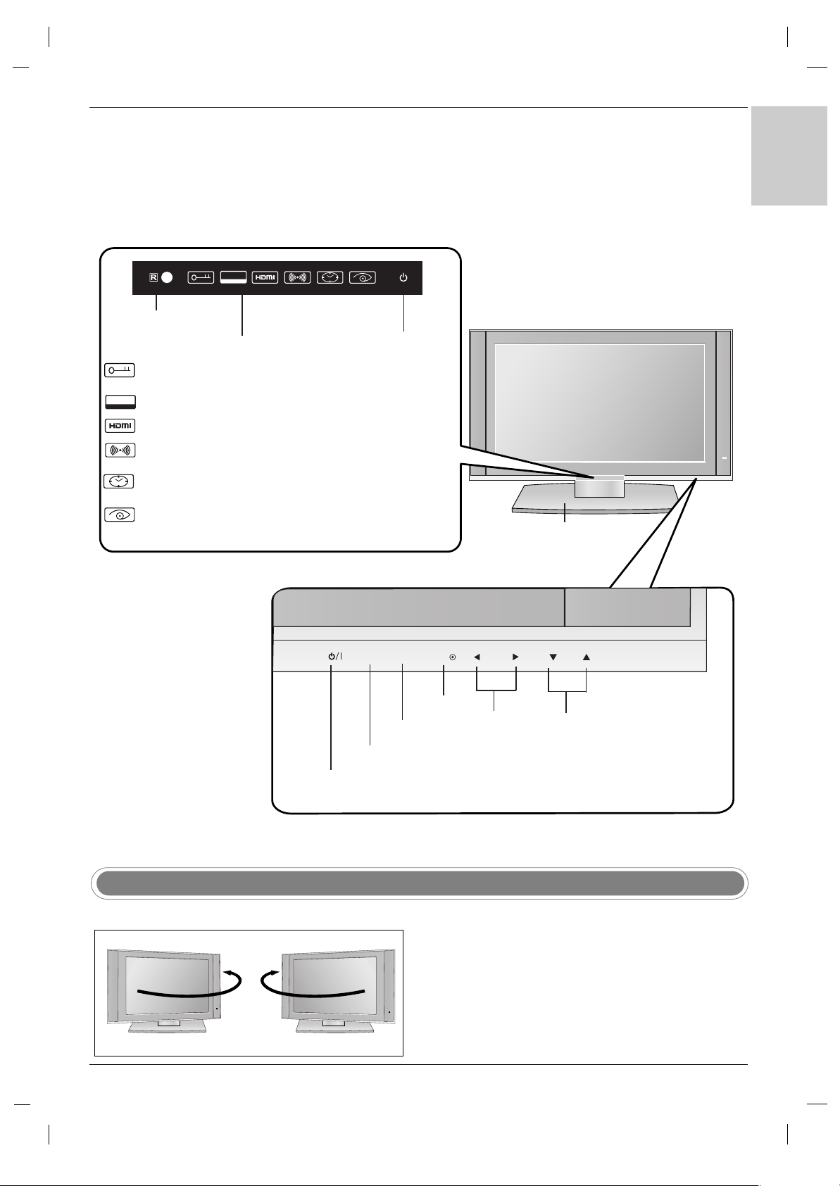
- This is a simplified representation of front panel.
- Here shown may be somewhat different from your TV.
INPUT Button
Volume
(
F / G)
Buttons
Remote Control
Sensor
Programme
(
EE/ DD
)
Buttons
MENU Button
OK Button
ON/OFF Button
Stand
(This feature is not available
for all models)
Child Lock On mode
(Refer to p.40)
RGB-PC, HDMI-PC input
SSM-SRS TSXT mode
(Refer to p.34)
Sleep timer mode
(Refer to p.39)
HDMI-DTV input
Intelligent eye
(Refer to p.31)
Power/Standby Indicator
(rr)
• illuminates red in standby mode.
• illuminates green when the set is
switched on.
Index
Controls
Controls
Introduction
Introduction
RGB
PC
- The TV can be conveniently swiveled on its stand 30° to
the left or right to provide the optimum viewing angle.
Swivel Stand
- This feature is not available for all models.
Page 6
6
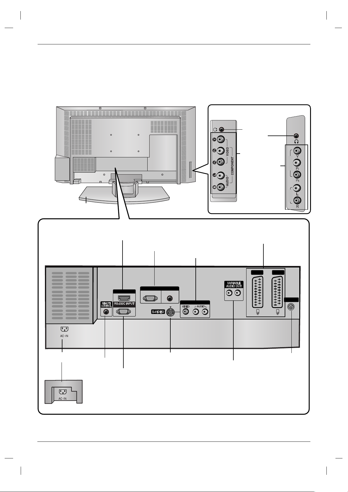
COMPONENT
IN
VIDEO
AUDIO
HDMI/DVI IN
(CONTROL & SERVICE)
LR
RGB IN
AUDIO(RGB/DVI)
RGB(PC-DTV)
AV IN 3
R
L
(MONO)
AV 1 AV 2
ANTENNA
COMPONENT
input
(Y,P
B,PR / Audio)
Headphone
Socket
Connection Options (Model: 32LB1R
Connection Options (Model: 32LB1R
**/
**/
37LB1R
37LB1R
**
**
)
)
Introduction
Introduction
Stand (This feature is not available
for all models)
Remote Control Port
Euro Scart Socket
(AV1/AV2)
HDMI (High Definition Multimedia Interface)/DVI input
RS-232C Input
Variable AUDIO OUT ports
RGB Input
AV3 (Video/Audio) Input
Antenna Input
AC Input
S-Video Input
- Here shown may be somewhat different from your TV.
32LB1R
**
37LB1R
**
37LB1R
**
Page 7

7
ENGLISH
Connection Options (Model: 42LB1R
Connection Options (Model: 42LB1R
**
**
)
)
COMPONENT input
(Y,PB,PR / Audio)
Headphone Socket
Stand (This feature is not
available for all models)
Remote Control Port
HDMI (High Definition Multimedia Interface)/DVI input
RS-232C Input
Variable AUDIO OUT ports
RGB Input
S-Video Input
Antenna Input
AC Input
- Here shown may be somewhat different from your TV.
AV3 (Video/Audio) Input
Euro Scart Socket
(AV1/AV2)
COMPONENT
IN
VIDEO
AUDIO
HDMI/DVI IN
(CONTROL & SERVICE)
RGB IN
RGB(PC-DTV)
AUDIO(RGB/DVI)
AV IN 3
L(MONO)
AV 1 AV 2
LR
R
ANTENNA
Page 8

8
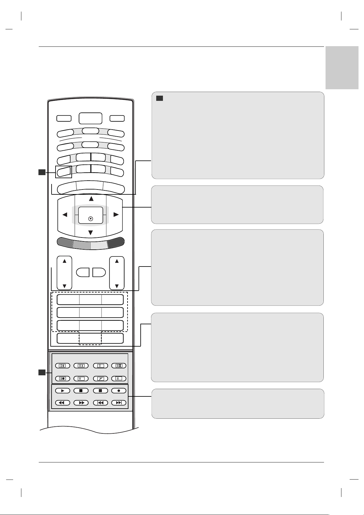
MODE
Selects the remote operating modes. :TV, DVD, VCR, AUDIO, CABLE
or STB
PIP BUTTONS
PIP (Refer to p.48)
Switches the sub picture PIP, DW, POP or off mode.
PIP PR - /+ (Refer to p.51)
Selects a programme for the sub picture.
SWAP (Refer to p.51)
Alternates between main and sub picture.
PIP INPUT (Refer to p.48)
Selects the input mode for the sub picture.
SIZE (Refer to p.49)
Adjusts the sub picture size.
POSITION (Refer to p.49)
Moves the sub picture to
DD /EE
or
FF / GG
direction.
*
COLOURED BUTTONS : These buttons are used for teletext (only
TELETEXT models) or Programme edit.
ZOOM - / ZOOM +
Enlarges or reduces the main picture size.
SLEEP
Sets the sleep timer. (Refer to p.39)
SSM (Sound Status Memory)
Recalls your preferred sound setting. (Refer to p.34)
PSM (Picture Status Memory)
Recalls your preferred picture setting. (Refer to p.31)
I/II
• Selects the sound output.
Remote Control Key Functions
Remote Control Key Functions
Introduction
Introduction
TV
Returns to TV viewing from any mode.
POWER
switches the set on from standby or off to standby.
INPUT
If you press the button once, the input source OSD
will appear on screen as shown. Press the
DD / EE
button and then OK button to select the desired input
source (
TV, AV 1 , AV 2 , AV 3 , S-Video, Component,
RGB PC/RGB DTV, or HDMI PC/ HDMI DTV).
1
1
1
1
TV
AV1
AV2
AV3
S-Video
Component
RGB PC
HDMI PC
TV
Input
TV
POWER
TV
AUDIO
PIP
TEXT
MENU
MODE
CABLE
ZOOM
SSM
ARC
DVD
-
ZOOM
PSM
INPUT
VCR
STB
+
SLEEP
I/II
EXIT
OK
PIP PR-
PIP PR+
SWAP
PIP INPUT
VOL
MUTE
LIST
PR
1 2 3
4 5 6
7809
FAVOURITE
POSITION
SIZE
TIME
REVEAL
INDEX
?
i
MIX
Q.VIEW
HOLD
MODE
M
Page 9
9
ENGLISH
TV
FAVOURITE
Q.VIEW
POWER
1 2 3
4 5 6
7809
AUDIO
TEXT
PIP
CABLE
ZOOM
-
ZOOM
+
PSM
SSM
STB
SLEEP
I/II
MENU
ARC
VCR
DVD
MODE
OK
POSITION
TIME
REVEAL
?
MODE
M
MIX
SIZE
HOLD
INDEX
i
INPUT
TV
PIP PR-
PIP PR+
SWAP
PIP INPUT
VOL
PR
MUTE
LIST
EXIT
TELETEXT BUTTONS
These buttons are used for teletext.
For further details, see the ‘Teletext’ section (Refer to p.52).
MENU
Selects a menu.
ARC
Selects your desired picture format (Refer to p.44).
EXIT
Clears all on-screen displays and returns to TV viewing from any
menu.
DD/EE
/ F / G (up / down / left / right)
Selects or adjusts an item in the menu.
OK
Accepts your selection or displays the current mode.
VOL (Volume) D / E
Adjusts the volume.
MUTE
Switches the sound on or off.
LIST
Displays the programme table (Refer to p.30).
PR (Programme)
D / E
Selects a programme.
0-9 number buttons
• Selects a programme.
• Selects numbered items in a menu.
FAVOURITE
Displays the se
lected favourite programme
(Refer to p.30).
Q.VIEW
Returns to the previously viewed programme.
VCR/DVD Control buttons
Controls a LG video cassette recorder or DVD.
2
2
2
Page 10
10
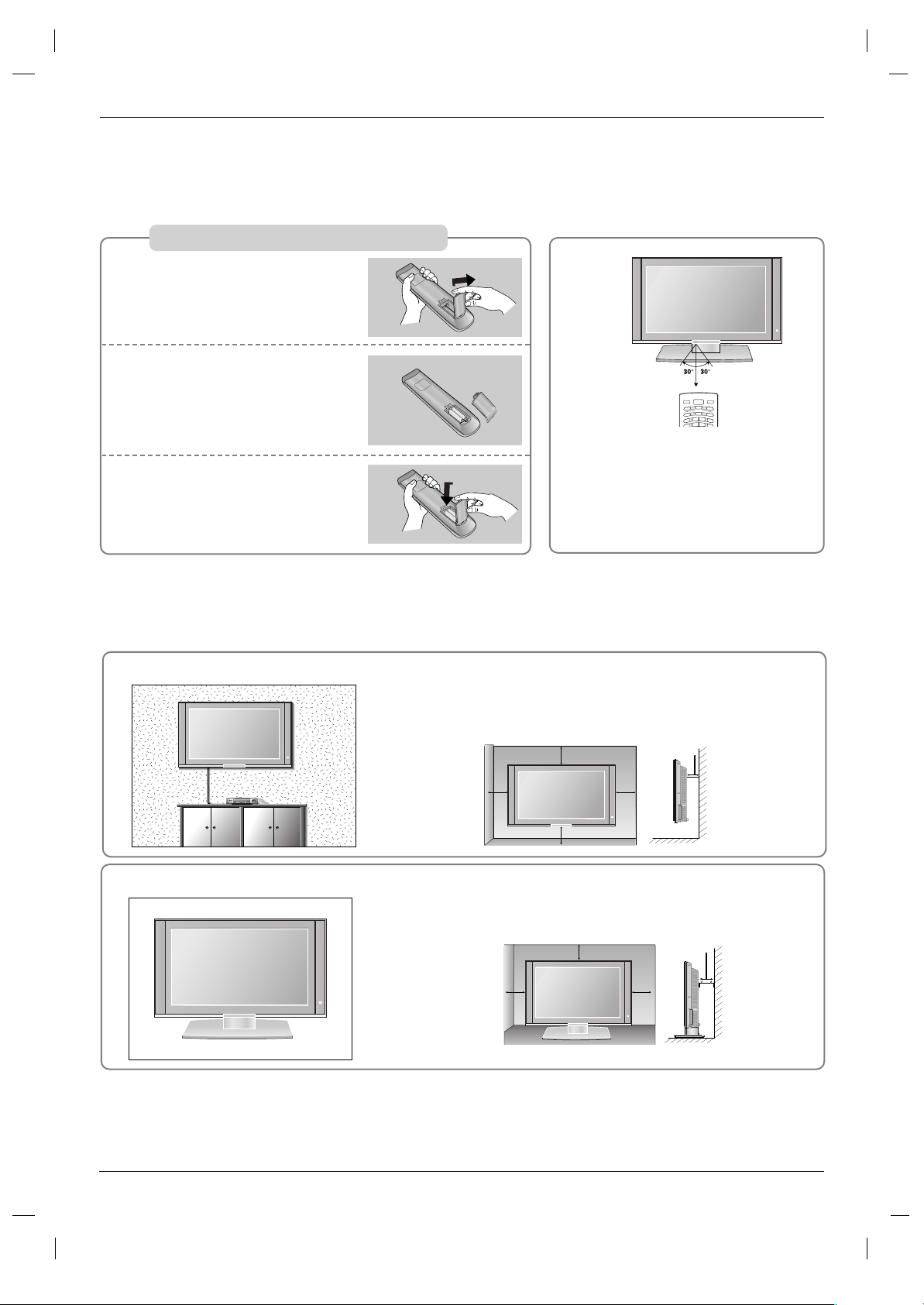
Installing Batteries
Open the battery compartment
cover on the back side.
Insert two 1.5V AA size batteries
in correct polarity (+ with +, - with
-). Don’t mix old or used batteries
with new ones.
Close the cover.
* Use a remote control 7 meter dis-
tance and 30 degree (left/right) within the receiving unit scope.
* Dispose of used batteries in the recycle bin to prevent environment.
TV
POWER
A
U
D
IO
T
P
IP
CABLE
Z
O
O
M
-
Z
O
O
M
+
PSM
S
S
M
ST
B
S
LE
E
P
I
/II
V
C
R
DVD
MODE
INPUT
T
V
1
2
3
Remote Control Key Functions
Remote Control Key Functions
Introduction
Introduction
For proper ventilation, allow a clearance of 4" on each side and from
the wall. Detailed installation instructions are available from your
dealer, see the optional Tilt Wall Mounting Bracket Installation and
Setup Guide.
Wall Mount: Horizontal installation
Desktop Pedestal Installation
4 inches
4 inches4 inches
4 inches
For proper ventilation, allow a clearance of 4" on each side and from
the wall.
4 inches
4 inches4 inches
4 inches
4 inches
Page 11
11
ENGLISH
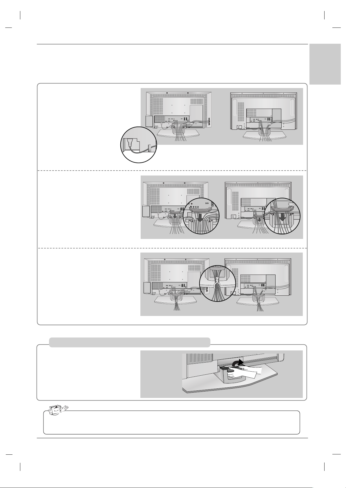
Connect the cables as necessary.
After connecting the cables neatly,
arrange the cables to the Cable
Holder.
To connect an additional equipment,
see the External equipment
Connections section.
Install the CABLE MANAGE-
MENT as shown.
1
2
Bundle the cables using the supplied twister holder.
3
Hold the CABLE MANAGEMENT with both hands and pull it
backward.
Basic Connection
Basic Connection
Installation
Installation
32/37 inch
37 inch
42 inch
32/37 inch
42 inch
32/37 inch
42 inch
How to remove the CABLE MANAGEMENT
Do not hold the CABLE MANAGEMENT when moving the product.
- If the product is dropped, you may be injured or the product may be broken.
Page 12
12
Installation
Installation
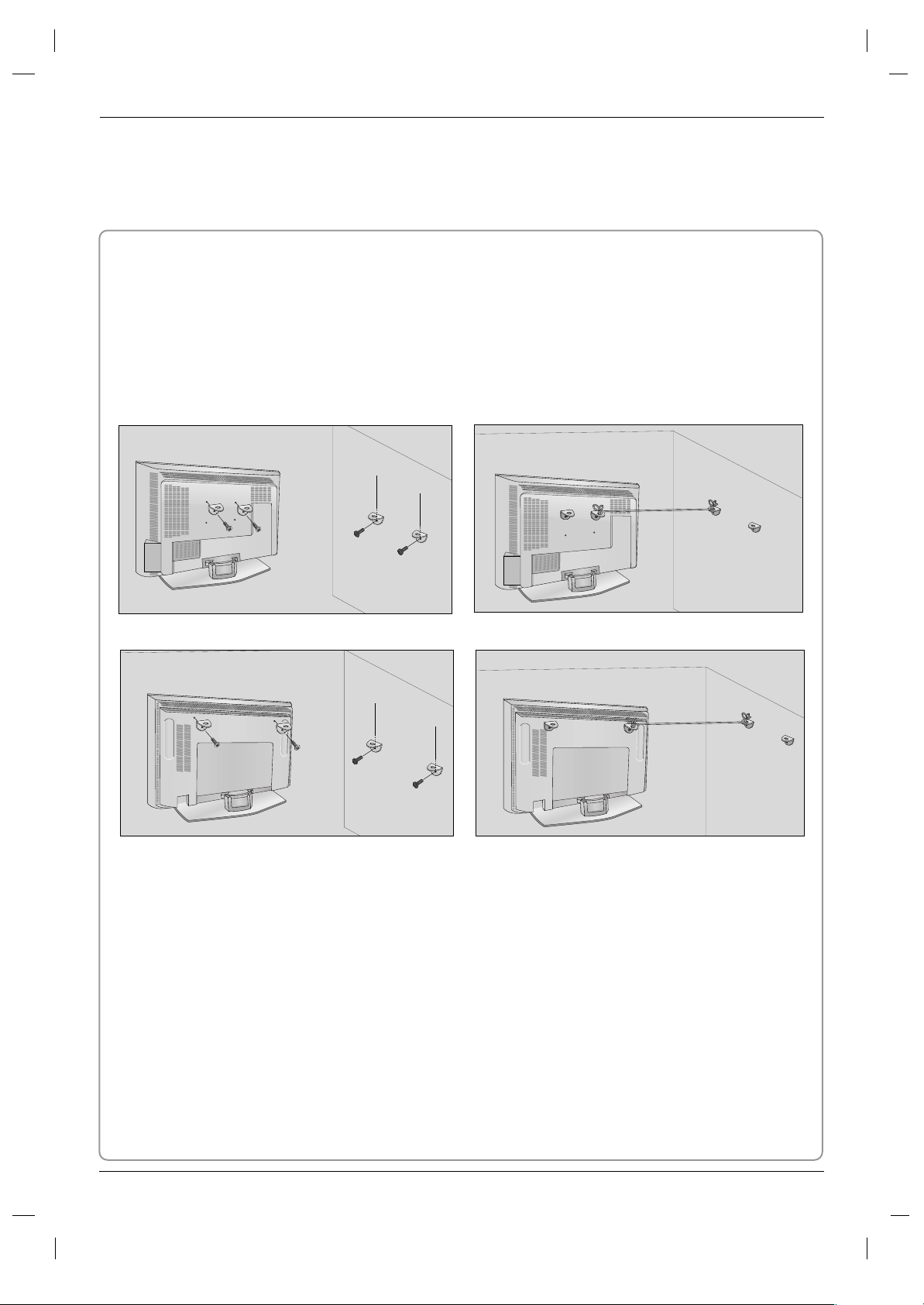
How to join the product assembly to the wall to protect the set tumbling
- Set it up close to the wall so the product doesn’t fall over when it is pushed backwards.
- The instructions shown below is a safer way to set up the product, which is to fix it on the wall so the product doesn’t fall over when it is pulled in the forward direction. It will prevent the product from falling forward and hurting people. It will also prevent the product from damage caused by fall. Please make sure
that children don’t climb on or hang from the product.
32/37 inch
Notes
• When moving the product to another place undo the ropes first.
• Use a product holder or a cabinet that is big and strong enough for the size and weight of the product.
• To use the product safely make sure that the height of the bracket that is mounted on the wall is same
as that of the product.
2
1
3
2
1
3
Use the bracket and the bolt to fix the product to the wall as shown in the picture.
Secure the bracket with the bolt (not provided as parts of the product, must purchase separately) on
the wall.
Use a sturdy rope (not provided as parts of the product, must purchase separately) to tie the product.
It is safer to tie the rope so it becomes horizontal between the wall and the product.
1
2
3
42 inch
Page 13
13
ENGLISH
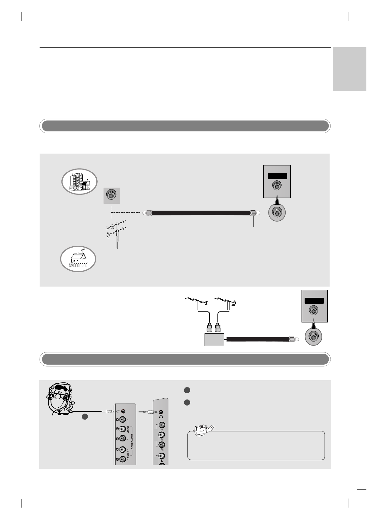
Antenna Connection
To prevent the equipment damage, never plug in any power cords until you have finished connecting all
equipment.
External Equipment Connections
External Equipment Connections
- For optimum picture quality, adjust antenna direction.
- An antenna cable and converter are not supplied.
•
In poor signal areas, to get better picture quality, install a signal amplifier to the antenna as shown to the right.
• If signal needs to be split for two TVs, use an antenna sig-
nal splitter for connection.
Signal
Amplifier
UHF
VHF
Multi-family Dwellings/Apartments
(Connect to wall antenna socket)
Single-family Dwellings /Houses
(Connect to wall jack for outdoor antenna)
Outdoor Antenna
Wall Antenna Socket
VHF Antenna
UHF Antenna
RF Coaxial Wire (75 ohm)
Turn clockwise to tighten.
ANTENNA
Headphone Socket
1
2
Plug the headphone into the headphone socket.
To adjust the headphone volume, press the VOL
DD /EE
button. If you press the MUTE button, the
sound from the headphone is switched off.
COMPONENT
IN
VIDEO
- You can listen to the sound through the headphone.
• While you are listening to sound through a headphone,
TV speakers will not be heard.
1
32 inch
37/42 inch
ANTENNA
Page 14
14
External Equipment Connections
External Equipment Connections
Installation Instruction
Installation Instruction
- To avoid picture noise (interference), leave an adequate distance between the VCR and TV.
- Typically a frozen still picture from a VCR. If the 4:3 picture format is used; the fixed images on the sides of the screen
may remain visible on the screen.
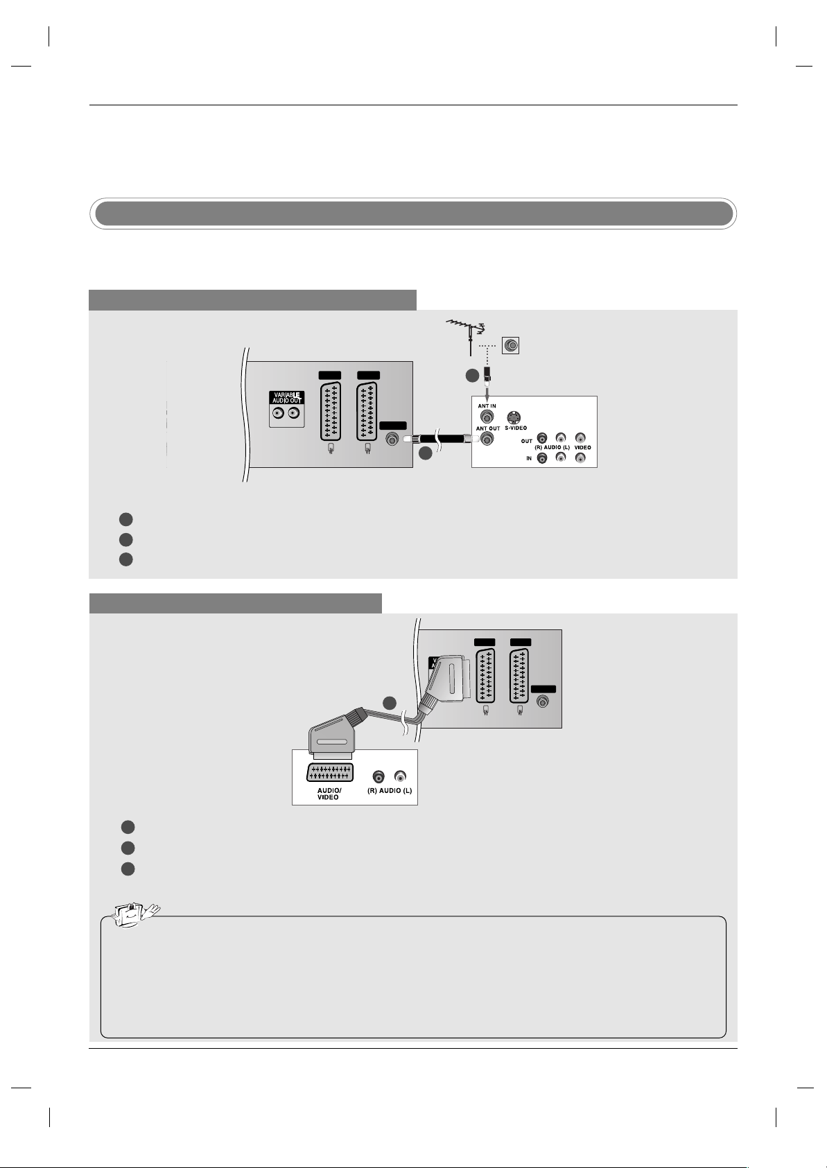
VCR Setup
When connecting with an antenna cable
1
2
3
LR
AV IN 3
R
L
(MONO)
AV 1 AV 2
ANTENNA
Connect the ANT OUT socket of the VCR to the Antenna socket on the set.
Connect the antenna cable to the ANT IN socket of the VCR.
Press the PLAY button on the VCR and match the appropriate programme between the TV and VCR for viewing.
When connecting with a Scart cable
• If your VCR outputs an AV switching signal via the AV 1 or AV2 scart sockets, the set will switch to AV1 input source automati-
cally. But if you want to keep on watching TV mode, press the PR
DD /EE
or number buttons.
• You can also record programmes received by the TV on video tape.
• The signal type RGB (the signals red, green and blue) can only be selected for the AV1 scart socket and the AV1 input source
can be received. These signals are transmitted, for example, by a pay TV decoder, game machine or photo CD unit, etc and that
digital signal can be recorded via AV1 scart socket.
• If the AV1 , AV2 scart sockets have been connected to the VCRs simultaneously, only the AV2 input source can be received.
HDMI/DVI IN
(CONTROL & SERVICE)
LR
RGB IN
AUDIO(RGB/DVI)
RGB(PC-DTV)
AV IN 3
R
L
(MONO)
AV 1 AV 2
ANTENNA
1
2
3
Connect the scart socket of the VCR to the AV1 scart socket on the set. Please use shielded scart cable.
Insert a video tape into the VCR and press PLAY on the VCR. (Refer to the VCR owner’s manual.)
Select
AV 1 input source with using the INPUT button on the remote control.
- If connected to AV2 scart socket, select
AV 2 input source.
1
2
TV Back panel
VCR
VCR
1
TV Back panel
Page 15
15
ENGLISH
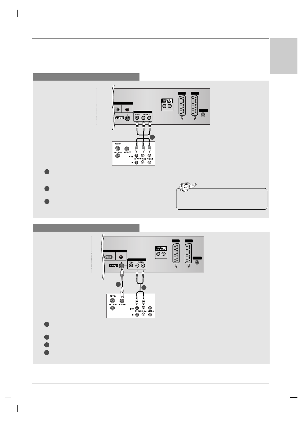
When connecting with a RCA cable
LR
RGB IN
AUDIO(RGB/DVI)
RGB(PC-DTV)
AV IN 3
R
L
(MONO)
AV 1 AV 2
ANTENNA
VCR
1
1
2
3
Connect the AUDIO/VIDEO jacks between TV and VCR.
Match the jack colours (Video = yellow, Audio Left = white, and
Audio Right = red)
Insert a video tape into the VCR and press PLAY on the VCR.
(Refer to the VCR owner’s manual.)
Select
AV 3 input source with using the INPUT button on the
remote control.
• If you have a mono VCR, connect the audio
cable from the VCR to the AUDIO L/MONO
jack of the set.
When connecting with an S-Video cable
LR
RGB IN
AUDIO(RGB/DVI)
RGB(PC-DTV)
AV IN 3
R
L
(MONO)
AV 1 AV 2
ANTENNA
VCR
1
1
2
2
3
4
Connect the S-VIDEO output of the VCR to the S-VIDEO input on the set. The picture quality is improved; compared to connecting a regular VCR to the Video input.
Connect the AUDIO jacks between TV and VCR.
Insert a video tape into the VCR and press PLAY on the VCR. (Refer to the VCR owner’s manual.)
Select
S-Video input source with using the INPUT button on the remote control.
TV Back panel
TV Back panel
Page 16
16
External Equipment Connections
External Equipment Connections
Installation
Installation
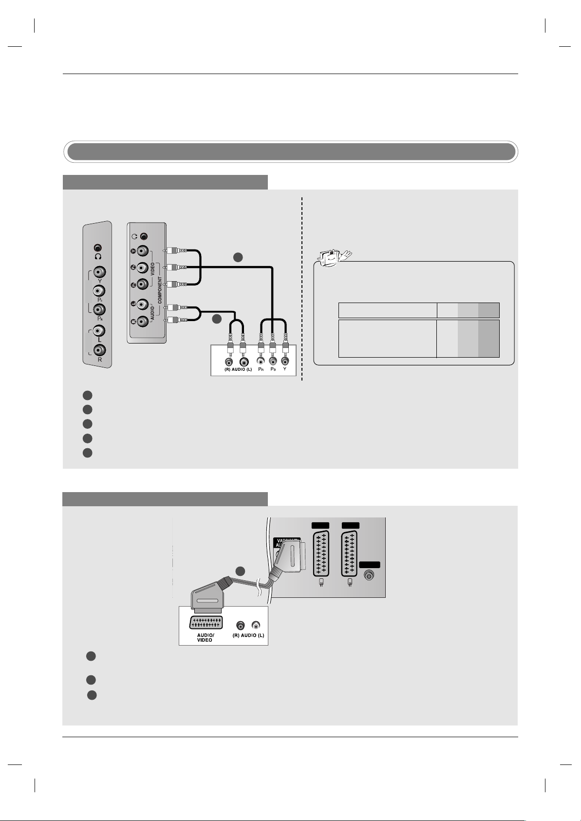
When connecting with a Euro scart cable
LR
AUDIO(RGB/DVI)
AV IN 3
R
L
(MONO)
AV 1 AV 2
ANTENNA
DVD
1
1
2
3
Connect the Euro scart socket of the DVD player to the AV 1 Euro scart socket on the set. Please use shielded
scart cable.
Turn on the DVD player, insert a DVD.
Select
AV 1 input source with using the INPUT button on the remote control.
- If connected to AV2 Euro scart socket, select
AV 2 input source.
DVD Setup
When connecting with a component cable
DVD
1
1
2
2
3
4
5
Connect the video outputs (Y, P
B, PR) of the DVD player to the COMPONENT VIDEO (Y, PB, PR) jacks on the set.
Connect the audio outputs of the DVD player to the COMPONENT AUDIO jacks on the set.
Turn on the DVD player, insert a DVD.
Select
Component input source with using the INPUT button on the remote control.
Refer to the DVD player's manual for operating instructions.
• Component Input ports
To get better picture quality, connect a DVD player to
the component input ports as shown below.
Y PB
PR
Component ports on the TV
Y
Y
Y
Y
Pb
B-Y
Cb
PB
Pr
R-Y
Cr
PR
Video output ports
on DVD player
TV Back panel
TV side panel
32 inch
COMPONENT
IN
VIDEO
AUDIO
37/42 inch
Page 17
17
ENGLISH
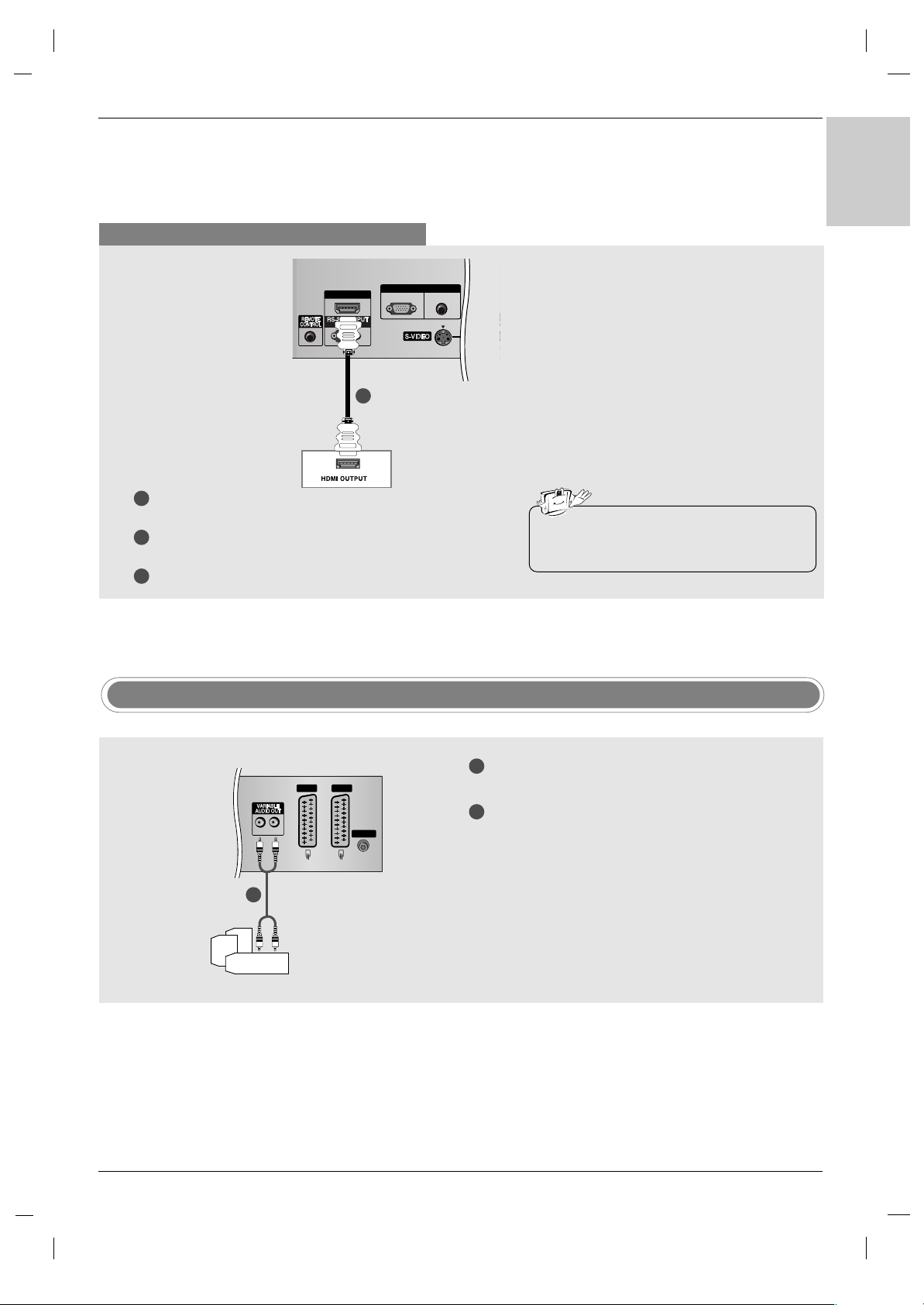
When connecting with a HDMI cable
1
2
3
Connect the HDMI output of the DVD player to the HDMI/DVI IN
jack on the set.
Select
HDMI DTV input source with using the INPUT button on
the remote control.
Refer to the DVD player's manual for operating instructions.
• TV can receive the video and audio signal
simultaneously with using a HDMI cable.
HDMI/DVI IN
(CONTROL & SERVICE)
RGB IN
AUDIO(RGB/DVI)
RGB(PC-DTV)
AV IN
L(MO
DVD
1
TV Back panel
External Stereo
1
2
Connect the input jack of the stereo’s amplifier to
the VARIABLE AUDIO OUT jacks on the set.
Set up your speakers through your analog stereo
amplifier, according to the instructions provided
with the amplifier.
• When connecting with external audio equipments,
such as amplifiers or speakers, please turn the TV
speakers off. (Refer to p.36)
LR
AV 1 AV 2
ANTENNA
- Use to connected either an external amplifier, or add a sub-woofer to your surround sound system.
1
Analog Stereo Amplifier
TV Back panel
Page 18
18
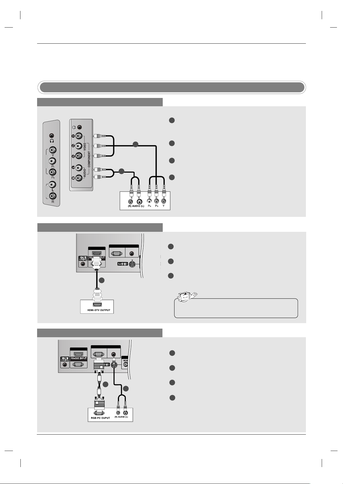
When connecting with a component cable
When connecting with a HDMI cable
1
1
2
2
3
4
Connect the video outputs (Y, PB, PR) of the digital settop box to the COMPONENT VIDEO (Y, PB, PR) jacks
on the set.
Connect the audio outputs of the digital set-top box to
the COMPONENT AUDIO jacks on the set.
Turn on the digital set-top box. (Refer to the owner’s
manual for the digital set-top box.)
Select
Component input source with using the
INPUT button on the remote control.
1
1
2
3
Connect the HDMI output of the digital set-top box to
the HDMI/DVI IN jack on the set.
Turn on the digital set-top box. (Refer to the owner’s
manual for the digital set-top box.)
Select
HDMI DTV input source with using the INPUT
button on the remote control.
DTV Receiver (Set-top Box)
DTV Receiver (Set-top Box)
STB ( Set-Top Box) Setup
When connecting with a
D-sub cable
1
1
2
2
3
4
Connect the RGB output of the digital set-top box to
the RGB (PC-DTV) jack on the set.
Connect the audio outputs of the set-top box to the
AUDIO (RGB/DVI) jack on the set.
Turn on the digital set-top box. (Refer to the owner’s
manual for the digital set-top box.)
Select
RGB DTV input source with using the
INPUT button on the remote control.
DTV Receiver (Set-top Box)
External Equipment Connections
External Equipment Connections
Installation
Installation
TV Back panel
TV Back panel
• TV can receive the video and audio signal simultaneously with using a HDMI cable.
TV side panel
32 inch
COMPONENT
IN
VIDEO
AUDIO
37/42 inch
HDMI/DVI IN
(CONTROL & SERVICE)
HDMI/DVI IN
(CONTROL & SERVICE)
RGB(PC-DTV)
RGB IN
RGB IN
AUDIO(RGB/DVI)
RGB(PC-DTV)
AUDIO(RGB/DVI)
AV IN 3
AV IN 3
L
(MONO)
R
L
L
(MONO)
R
Page 19

19
ENGLISH
When connecting with a HDMI to DVI cable
1
1
2
3
Connect the DVI output of the digital set-top box to the
HDMI/DVI IN jack on the set.
Connect the audio outputs of the set-top box to the AUDIO
(RGB/DVI) jack on the set.
Turn on the digital set-top box. (Refer to the owner’s
manual for the digital set-top box.)
Select
HDMI DTV input source with using the INPUT
button on the remote control.
DTV Receiver (Set-top Box)
TV Back panel
Cable TV Setup
- After subscribing to a local cable TV service and installing a converter, you can watch cable TV programmes.
- For further cable TV information, contact a local cable service provider.
When connecting with an S-Video cable
1
2
Cable Box
HDMI/DVI IN
(CONTROL & SERVICE)
LR
RGB IN
AUDIO(RGB/DVI)
RGB(PC-DTV)
AV IN 3
R
L
(MONO)
AV 1
1
2
3
4
Connect the S-VIDEO output of the Cable Box to the
S-VIDEO input on the set. The picture quality is
improved.
Connect the AUDIO jacks between TV and Cable
Box.
Select
S-Video input source with using the INPUT
button on the remote control.
Select programmes with the cable box remote con-
trol.
TV Back panel
When connecting with a RCA cable
1
Cable Box
LR
RGB IN
AUDIO(RGB/DVI)
RGB(PC-DTV)
AV IN 3
R
L
(MONO)
ANT
1
2
3
Connect the AUDIO/VIDEO jacks between TV and
Cable Box. Match the jack colours (Video = yellow,
Audio Left = white, and Audio Right = red)
Select
AV 3 input source with using the INPUT button
on the remote control.
Select programmes with the cable box remote control.
TV Back panel
4
• If the STB has a DVI output and no HDMI output,
a separated audio connection is necessary.
HDMI/DVI IN
(CONTROL & SERVICE)
RGB(PC-DTV)
RGB IN
AUDIO(RGB/DVI)
AV IN 3
(MONO)
L
R
LR
Page 20
20
External Equipment Connections
External Equipment Connections
Installation
Installation
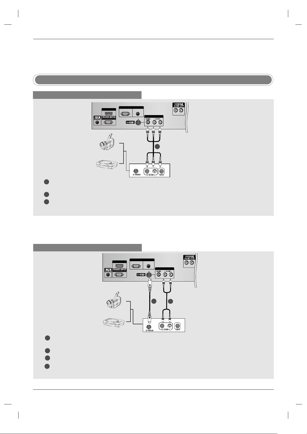
Camcorder
Video Game Set
1
1
2
3
Connect the AUDIO/VIDEO jacks between TV and external equipment. Match the jack colours (Video = yellow,
Audio Left = white, and Audio Right = red).
Select
AV 3 input source with using the INPUT button on the remote control.
Operate the corresponding external equipment. Refer to external equipment operating guide.
External AV Source Setup
When connecting with a RCA cable
When connecting with an S-Video cable
HDMI/DVI IN
(CONTROL & SERVICE)
LR
RGB IN
AUDIO(RGB/DVI)
RGB(PC-DTV)
AV IN 3
R
L
(MONO)
ANTENNA
1
1
2
2
3
4
Connect the S-VIDEO output of the external equipment to the S-VIDEO input on the set. The picture quality is
improved.
Connect the AUDIO jacks between TV and external equipment.
Select
S-Video input source with using the INPUT button on the remote control.
Operate the corresponding external equipment. Refer to external equipment operating guide.
Camcorder
Video Game Set
TV Back panel
TV Back panel
HDMI/DVI IN
(CONTROL & SERVICE)
RGB(PC-DTV)
RGB IN
AUDIO(RGB/DVI)
AV IN 3
(MONO)
L
R
LR
ANTENNA
Page 21

21
ENGLISH
Connect the DVI output of the PC to the HDMI/DVI IN jack on the set.
Connect the PC audio output to the AUDIO (RGB/DVI) jack on the set.
Turn on the PC and the set.
Select
HDMI PC input source with using the INPUT button on the remote control.
PC Setup
1
2
3
4
Connect the RGB output of the PC to the RGB (PC-DTV) jack on the set.
Connect the PC audio output to the AUDIO (RGB/DVI) jack on the set.
Turn on the PC and the set.
Select RGB PC input source with using the INPUT button on the remote control.
LR
RGB IN
AUDIO(RGB/DVI)
RGB(PC-DTV)
AV IN 3
R
L
(MONO)
AV 1 AV 2
ANTENNA
When connecting with a HDMI to DVI cable
When connecting with a D-sub cable
1
2
3
4
HDMI/DVI IN
(CONTROL & SERVICE)
LR
RGB IN
AUDIO(RGB/DVI)
RGB(PC-DTV)
AV IN 3
R
L
(MONO)
1
PC
• If the PC has a DVI output and no HDMI output, a
separated audio connection is necessary.
PC
TV Back panel
TV Back panel
Page 22

22
AC IN
- Connect the power cord correctly as shown.
Power Cord Connection
External Equipment Connections
External Equipment Connections
Installation
Installation
Resolution
Horizontal
Frequency(kHz)
Vertical
Frequency(Hz)
Supported display resolution
DPM (Display Power Management) mode
If the PC goes to power saving mode, the monitor automatically
switches to DPM mode.
If you don’t use the PC cable provided, DPM mode may not work.
- DPM mode is not available in HDMI PC mode.
Note
a. For optimum picture quality, use standard WXGA
1360x768 computer output at a 60Hz refresh rate.
Using other formats (VGA, SVGA, etc.) or refresh
rates may result in reduced picture quality. (To
change the computer video output format, please
refer to the operating manual for the computer you
are using).
b. If the message
No signal appears on the screen,
adjust the PC output to a format listed in the
Monitor Display Specifications table.
c. The synchronization input form for Horizontal and
Vertical frequencies is separate.
720 x 400
640 x 480
800 x 600
832 x 624
1024 x 768
(XGA)
1280 x 768
(WXGA)
1360 x 768
(WXGA)
1366 x 768
(WXGA)
31.468
31.469
37.500
37.879
46.875
49.725
48.363
56.470
60.123
47.776
47.720
47.720
70
60
75
60
75
75
60
70
75
60
60
60
AA
PC (Monitor Display Specifications)
AA
DTV
480i
576i
480p
576p
720p
1080i
Mode
Component
o
o
o
o
o
o
RGB (DTV)
x
x
o
o
o
o
HDMI (DTV)
x
x
o
o
o
o
Terminal
32/37 inch
42 inch
Page 23

23
ENGLISH
FAVOURITE
Q.VIEW
LIST
PIP PR-
PIP PR+
SWAP
PIP INPUT
ARC
PSM
TEXT
AUDIO
PIP
CABLE
ZOOM
-
ZOOM
+
STB
SLEEP
VCR
DVD
MODE
TV
TV
POWER
SSM
I/II
OK
POSITION
TIME
REVEAL
?
MODE
M
MIX
SIZE
i
INPUT
VOL
PR
MUTE
MENU
EXIT
HOLD
INDEX
0
1 2 3
4 5 6
7 8 9
Press the MENU button and then
DD / EE
button to select the Special menu.
Press the
GG
button and then
DD / EE
button to select
Language.
Press the
GG
button and then
DD / EE
button to select your desired language.
All the on screen displays will appear in the selected language.
Press the OK button.
Press the EXIT button to return to TV viewing.
On screen language selection
Basic Operation
Basic Operation
Operation
Operation
First, make all equipment connections. Connect the AC power cord into the TV,
then plug the power cord into a wall outlet. Press the POWER button located on
the TV to turn on the TV. The power indicator will light.
• In the standby mode, press the POWER, PR
DD / EE
, TV, INPUT or number but-
tons on the remote control to turn on the TV.
If you want to turn the TV off, press the POWER button located on the remote
control. If you intend to be away on vacation, disconnect the plug from the
wall outlet.
1
2
Turning On/Off the TV
Press the VOL
DD / EE
button to adjust the volume.
If you want to switch the sound off, press the MUTE button.
You can cancel this function by pressing the MUTE, VOL
DD / EE
, I/II or SSM button.
1
2
1
2
3
4
5
Volume Adjustment
Press the PR
DD / EE
or NUMBER buttons to select a programme number.
1
Programme selection
Page 24

24
STATION G
PICTURE
SOUND
TIME
SPECIAL
SCREEN
PIP/DW
Auto programme
Manual programme
Programme edit
Favourite programme
STATION
PICTURE G
SOUND
TIME
SPECIAL
SCREEN
PIP/DW
PSM
CSM
ACM
Contrast 100
Brightness 45
Colour 50
Sharpness 50
STATION
PICTURE
SOUND G
TIME
SPECIAL
SCREEN
PIP/DW
SSM
BBE
AVL
Balance 0
Treble 50
Bass 50
TV speaker
STATION
PICTURE
SOUND
TIME G
SPECIAL
SCREEN
PIP/DW
Clock
Off time
On time
Auto sleep
STATION
PICTURE
SOUND
TIME
SPECIAL G
SCREEN
PIP/DW
Language
Child lock
Set ID
Demo
Index
STATION
PICTURE
SOUND
TIME
SPECIAL
SCREEN G
PIP/DW
Auto config.
Manual config.
XGA Mode
ARC
Zoom +/Position
Cinema
NR
Reset
STATION
PICTURE
SOUND
TIME
SPECIAL
SCREEN
PIP/DW G
Input
DW
PIP
PIP Input
Win. size
Win. position
PIP Transparency
Press the MENU button and then DD/ EEbutton to display each menu.
Press the GGbutton and then DD/ EEbutton to select a menu item.
Change the setting of an item in the sub or pull-down menu with
F / G button.
You can move to the higher level menu by pressing the OK or MENU button.
1
2
3
How to adjust the OSD screen
STATION menu
PICTURE menu
SOUND menu
PIP/DW menu
TIME menu
SPECIAL menu
SCREEN menu
Note
a. The OSD (On Screen Display) function enables you to adjust the screen status conveniently since it pro-
vides graphical presentation.
b. In this manual, the OSD (On Screen Display) may be different from your TV’s because it is just example
to help the TV operation.
c. In the teletext mode, menus are not displayed
Basic Operation
Basic Operation
Operation
Operation
Page 25

25
ENGLISH
Setting up TV stations
Setting up TV stations
- All stations that can be received
are stored by this method. It is
recommended that you use auto
programme during installation of
this set.
Auto programme tuning
STATION
PICTURE
SOUND
TIME
SPECIAL
SCREEN
PIP/DW
Prev.
Menu
Auto programme
Manual programme
Programme edit
Favourite programme
System BG
Storage from 1
Start
Press the MENU button and then
DD / EE
button to select the STATION menu.
Press the
GG
button and then
DD / EE
button to select Auto programme.
Press the
GG
button and then
DD / EE
button to select System.
Press the
FF / GG
button to select a TV system menu;
BG : PAL B/G, SECAM B/G (Europe/East Europe)
I : PAL I/II (U.K./Ireland)
DK : PAL D/K, SECAM D/K (East Europe)
L : SECAM L/L’ (France)
Press the
DD / EE
button to select Storage from.
Press the
FF / GG
button or NUMBER buttons to select the beginning programme number. If you use NUMBER buttons, any number under 10 is
entered with a numeric ‘0’ in front of it, i.e.‘05’ for 5.
Press the
DD / EE
button to select Start.
Press the
GG
button to begin auto programming.
All receivable stations are stored. The station name is stored for stations
which broadcast VPS (Video Programme Service), PDC (Programme
Delivery Control) or TELETEXT data. If no station name can be assigned to
a station, the channel number is assigned and stored as
C (V/UHF 01-69)
or
S (Cable 01-47), followed by a number.
To stop auto programming, press the MENU button.
When auto programming is completed, the Programme edit menu appears
on the screen. See the Programme edit section to edit the stored pro-
gramme.
Press the EXIT button to return to normal TV viewing.
1
2
3
4
5
6
7
8
9
Up to 100 TV stations can be stored by programme numbers (0 to 99). Once you have preset the stations,
you will be able to use the
DD / EE
or NUMBER buttons to scan the stations you have programmed.
Stations can be tuned using automatic or manual modes.
Auto programme
GG
STATION G
PICTURE
SOUND
TIME
SPECIAL
SCREEN
PIP/DW
Auto programme
Manual programme
Programme edit
Favourite programme
Page 26

26
Setting up TV stations
Setting up TV stations
- Manual programme lets you manually tune and arrange the stations
in whatever order you desire.
Manual programme tuning
STATION
PICTURE
SOUND
TIME
SPECIAL
SCREEN
PIP/DW
Prev.
Menu
Auto programme
Manual programme
Programme edit
Favourite programme
Storage 5
System BG
Band V/UHF
Channel 5
Fine
Search
Name
C 05
Press the MENU button and then
DD / EE
button to select the STATION menu.
Press the
GG
button and then
DD / EE
button to select Manual programme.
Press the
GG
button and then
DD / EE
button to select Storage.
Press the
FF / GG
button or NUMBER buttons to select the desired programme number (0 to 99). If you use NUMBER buttons, any number under
10 is entered with a numeric ‘0’ in front of it, i.e. ‘05’ for 5.
Press the
DD / EE
button to select System.
Press the
FF / GG
button to select a TV system menu;
BG : PAL B/G, SECAM B/G (Europe/East Europe)
I : PAL I/II (U.K./Ireland)
DK : PAL D/K, SECAM D/K (East Europe)
L : SECAM L/L’ (France)
Press the
DD / EE
button to select Band.
Press the
FF / GG
button to select V/UHF or Cable.
Press the
DD / EE
button to select Channel.
You can select the desired programme number with the
FF / GG
button or
number buttons. If possible, select the programme number directly with the
number buttons. Any number under 10 is entered with a numeric ‘0’ in front
of it, i.e. ‘05’ for 5.
Press the
DD / EE
button to select Search.
Press the
FF / GG
button to commence searching. If a station is found the
search will stop.
Press the OK button to store it.
To store another station, repeat steps 3 to 13.
Press the EXIT button to return to normal TV viewing.
1
2
3
4
5
6
7
8
9
10
11
12
13
14
15
Manual programme
GG
STATION G
PICTURE
SOUND
TIME
SPECIAL
SCREEN
PIP/DW
Auto programme
Manual programme
Programme edit
Favourite programme
Page 27

27
ENGLISH
- Normally fine tuning is only necessary if reception is poor.
Fine tuning
STATION
PICTURE
SOUND
TIME
SPECIAL
SCREEN
PIP/DW
Auto programme
Manual programme
Programme edit
Favourite programme
Storage 5
System BG
Band V/UHF
Channel 5
Fine
FF
G
Search
Name
C 05
Store
Press the MENU button and then
DD / EE
button to select the STATION menu.
Press the
GG
button and then
DD / EE
button to select Manual programme.
Press the
GG
button and then
DD / EE
button to select Fine.
Press the
FF / GG
button to to fine tune for the best picture and sound.
Press the OK button to store it.
Press the EXIT button to return to normal TV viewing.
1
2
3
4
5
6
Manual programme
GG
STATION G
PICTURE
SOUND
TIME
SPECIAL
SCREEN
PIP/DW
Auto programme
Manual programme
Programme edit
Favourite programme
Page 28

28
Setting up TV stations
Setting up TV stations
Assigning a station name
- You can assign a station name
with five characters to each programme number.
STATION
PICTURE
SOUND
TIME
SPECIAL
SCREEN
PIP/DW
Auto programme
Manual programme
Programme edit
Favourite programme
Store
Storage 5
System BG
Band V/UHF
Channel 5
Fine
Search
Name
G
C 05
Press the MENU button and then
DD / EE
button to select the STATION menu.
Press the
GG
button and then
DD / EE
button to select Manual programme.
Press the
GG
button and then
DD / EE
button to select Name.
Press the
GG
button and then
DD / EE
button. You can use a blank, +, -, the
number
0 to 9 and the alphabet A to Z.
Press the
FF / GG
button to select the position and make your choice of
the second character, and so on.
Press the OK button to store it.
Press the EXIT button to return to normal TV viewing.
1
2
3
4
5
6
7
Manual programme
GG
STATION G
PICTURE
SOUND
TIME
SPECIAL
SCREEN
PIP/DW
Auto programme
Manual programme
Programme edit
Favourite programme
Page 29

29
ENGLISH
- This function enables you to
delete or skip the stored programmes. Also you can move
some stations to other programme numbers or copy a
blank station data into the selected programme number.
Programme edit
STATION
PICTURE
SOUND
TIME
SPECIAL
SCREEN
PIP/DW
Prev.
Menu
Auto programme
Manual programme
Programme edit
Favourite programme
To set
Prev.
DD EE FF GG
Menu
Programme edit
0 - - - - - 5 C 05
1 BLN 2 6 C 07
2 C 01 7 C 55
3 C 04 8 S 27
4 C 05 9 S 29
2 C 01
Delete
Move
Copy
Skip
Press the MENU button and then
DD / EE
button to select the STATION menu.
Press the
GG
button and then
DD / EE
button to select Programme edit.
Press the GGbutton to display the
Programme edit menu.
AA
Deleting a programme
1. Select a programme to be deleted with the
DD / EE
/
FF / GG
button.
2. Press the RED button twice.
The selected programme is deleted, all the following programmes are
shifted up one position.
AA
Copying a programme
1. Select a programme to be copied with the
DD / EE
/
FF / GG
button.
2. Press the GREEN button.
All the following programmes are shifted down one position.
AA
Moving a programme
1. Select a programme to be moved with the
DD / EE
/
FF / GG
button.
2. Press the YELLOW button.
3. Move the programme to the desired programme number with the
DD / EE
/
FF / GG
button.
4. Press the YELLOW button again to release this function.
AA
Skipping a programme number
1. Select a programme number to be skipped with the
DD / EE
/
FF / GG
button.
2. Press the BLUE button. The skipped programme turns to blue.
3. Press the BLUE button again to release the skipped programme.
When a programme number is skipped it means that you will be unable
to select it using the
DD / EE
button during normal TV viewing. If you want
to select the skipped programme, directly enter the programme number
with the NUMBER buttons or select it in the programme edit or table
menu.
Press the EXIT button to return to normal TV viewing.
1
2
3
4
Programme edit
GG
STATION G
PICTURE
SOUND
TIME
SPECIAL
SCREEN
PIP/DW
Auto programme
Manual programme
Programme edit
Favourite programme
Page 30

30
Favourite programme
Calling the programme table
STATION
PICTURE
SOUND
TIME
SPECIAL
SCREEN
PIP/DW
Prev.
Menu
Auto programme
Manual programme
Programme edit
Favourite programme
FF
G
0 BLN 2
- - - - - - -
- - - - - - -
- - - - - - -
- - - - - - -
- - - - - - -
- - - - - - -
- - - - - - -
Press the MENU button and then
DD / EE
button to select the STATION menu.
Press theGGbutton and then
DD / EE
button to select Favourite programme.
Press theGGbutton.
Press the
DD / EE
button to select - - - - - - -.
Select a desired programme with the
FF / GG
button or NUMBER buttons. Any
number under 10 is entered with a numeric ‘0’in front of it, i.e.‘05’ for 5.
To store another programme, repeat steps 4 to 5.
You can store up to 8 programmes.
Press the EXIT button to return to normal TV viewing.
1
2
3
4
5
6
7
Favourite programme
GG
-
You can check the programmes
stored in the memory by displaying
the programme table.
1 2 3
4 5 6
7 8 9
MENU
ARC
OK
PIP PR-
PIP PR+
SWAP
PIP INPUT
VOL
PR
MUTE
LIST
EXIT
LIST
-
This function lets you select your
favourite programmes directly.
-
Repeatedly press the FAVOURITE but-
ton to select stored favourite programmes.
FAVOURITE
Q.VIEW
1 2 3
4 5 6
7809
POSITION
SIZE
HOLD
INDEX
FAVOURITE
AA
Displaying programme table
Press the LIST button to display the Programme table menu.
The programme table appears on the screen. One programme table contains ten programmes as below.
AA
Selecting a programme in the programme table
Select a programme with the
DD / EE
/
FF / GG
button. Then press the OK but-
ton. The set switches to the chosen programme number.
AA
Paging through a programme table
There are 10 programme table pages in which contain 100 programmes.
Pressing the
DD / EE
/
FF / GG
button repeatedly turns the pages.
Press the EXIT button to return to normal TV viewing.
Note
a. You may find some blue programmes. They have been set up to
be skipped by auto programming or in the programme edit mode.
b. Some programmes with the channel number shown in the pro-
gramme table indicate there is no station name assigned.
DD EE FF GG
0 - - - - - 5 C 05
1 BLN 2 6 C 07
2 C 01 7 C 55
3 C 04 8 S 27
4 C 05 9 S 29
2 C 01
STATION G
PICTURE
SOUND
TIME
SPECIAL
SCREEN
PIP/DW
Auto programme
Manual programme
Programme edit
Favourite programme
Setting up TV stations
Setting up TV stations
Page 31

31
ENGLISH
- For initialize values (reset to default
settings), select the
Normal option.
- When adjusting colour temperature
options (
Red, Green, or Blue)
manually,
CSM automatically
changes to
User.
- This function adjusts the set for
the best picture appearance.
- When adjusting
Contrast,
Brightness, Colour,
Sharpness, and Tint (NTSC
only) manually, PSM automatically changes to
User.
-
Dynamic, Standard, and
Mild are programmed for opti-
mum picture reproduction at the
factory and cannot be changed.
- When the Intelligent eye function
is on, picture is automatically
adjusted to most suitable according to the surrounding conditions.
- You can also use the
PICTURE
menu to adjust PSM.
CSM (Colour Status Memory)
STATION
PICTURE
SOUND
TIME
SPECIAL
SCREEN
PIP/DW
Prev.
Menu
PSM
CSM
ACM
Contrast 100
Brightness 45
Colour 50
Sharpness 50
Cool
Normal
Warm
User
Red 0
Green 0
Blue 0
Press the MENU button and then
DD / EE
button to select the PICTURE menu.
Press the
GG
button and then
DD / EE
button to select CSM.
Press the
GG
button and then
DD / EE
button to select Cool, Normal, Warm,
or
User.
•
Cool
: To
see less intense colors with more blue.
•
Normal
:
To initialize values (reset to default settings).
•
Warm
:
To enhance hotter colors such as red.
•
User
:
To adjust red, green, blue to any colour temperature you prefer.
1. Press the
DD / EE
button to select User.
2. Press theGGbutton and then
DD / EE
button to select Red, Green, or Blue.
3. Press the
FF / GG
button to make appropriate adjustments.
Press the EXIT button to return to normal TV viewing.
Picture adjustment
Picture adjustment
PSM (Picture Status Memory)
Dynamic
Press the PSM button repeatedly to select the picture appearance setup
option as shown below:
Intelligent Eye, Dynamic, Standard, Mild,
or
User.
1
2
3
4
TV
POWER
AUDIO
TEXT
PIP
CABLE
ZOOM
-
ZOOM
+
PSM
SSM
STB
SLEEP
I/II
MENU
ARC
VCR
DVD
MODE
OK
INPUT
TV
EXIT
PSM
1
CSM
GG
STATION
PICTURE G
SOUND
TIME
SPECIAL
SCREEN
PIP/DW
PSM
CSM
ACM
Contrast 100
Brightness 45
Colour 50
Sharpness 50
Page 32

32
Picture adjustment
Picture adjustment
- XD is LG's unique picture improv-
ing technology to display a real HD
source through an advanced digital signal processing algorithm.
- When selecting
PSM options
(
Dynamic, Standard, or Mild),
XD is automatically change to On.
If
XD setting is Off, PSM is auto-
matically change to
User and
ACM function is not available.
-
XD function is not available in RGB
PC/HDMI PC mode.
Function
STATION
PICTURE
SOUND
TIME
SPECIAL
SCREEN
PIP/DW
Prev.
Menu
PSM
CSM
ACM
Contrast 100
Brightness 45
Colour 50
Sharpness 50
On
Off
Press the MENU button and then
DD / EE
button to select the PICTURE menu.
Press the
GG
button and then
DD / EE
button to select XD.
Press the
GG
button and then
DD / EE
button to select On or Off.
Press the EXIT button to return to normal TV viewing.
1
2
3
4
GG
STATION
PICTURE G
SOUND
TIME
SPECIAL
SCREEN
PIP/DW
PSM
CSM
ACM
Contrast 100
Brightness 45
Colour 50
Sharpness 50
- Adjust the ACM to select the
desired skin colour option.
-
ACM function is available in all
modes except RGB PC/HDMI PC
mode.
ACM (Active Colour Management)
STATION
PICTURE
SOUND
TIME
SPECIAL
SCREEN
PIP/DW
Prev.
Menu
PSM
CSM
ACM
Contrast 100
Brightness 45
Colour 50
Sharpness 50
Fleshtone 0
Greentone 0
Bluetone 0
Press the MENU button and then
DD / EE
button to select the PICTURE menu.
Press the
GG
button and then
DD / EE
button to select ACM .
Press the
GG
button and then
DD / EE
button to select Fleshtone, Greentone,
or
Bluetone.
Press the
FF / GG
button to make appropriate adjustments.
Press the EXIT button to return to normal TV viewing.
1
2
3
4
5
ACM
GG
STATION
PICTURE G
SOUND
TIME
SPECIAL
SCREEN
PIP/DW
PSM
CSM
ACM
Contrast 100
Brightness 45
Colour 50
Sharpness 50
Page 33

33
ENGLISH
STATION
PICTURE
SOUND
TIME
SPECIAL
SCREEN
PIP/DW
Prev.
Menu
PSM
CSM
ACM
Contrast 100
Brightness 45
Colour 50
Sharpness 50
- You can adjust picture
Contrast, Brightness,
Colour
, Sharpness and Tint
(NTSC only) to the levels you
prefer.
Manual Picture Adjustment
Press the MENU button and then
DD / EE
button to select the PICTURE menu.
Press the
GG
button and then
DD / EE
button to select the desired picture
option (
Contrast, Brightness, Colour, or Sharpness).
Press the
FF / GG
button to make appropriate adjustments.
Press the EXIT button to return to normal TV viewing.
• Only Contrast and Brightness are displayed in PC mode.
1
2
3
4
Contrast 100
GG
STATION
PICTURE G
SOUND
TIME
SPECIAL
SCREEN
PIP/DW
PSM
CSM
ACM
Contrast 100
Brightness 45
Colour 50
Sharpness 50
- When the set was connected to
external equipment with sRGB
function, it’s adjusted a colour
difference to display the equal
image each other.
- sRGB function is available in RGB
PC/HDMI PC mode.
sRGB
STATION
PICTURE
SOUND
TIME
SPECIAL
SCREEN
PIP/DW
Prev.
Menu
PSM
CSM
sRGB
Contrast 100
Brightness 45
On
Off
Press the MENU button and then
DD / EE
button to select the PICTURE menu.
Press the
GG
button and then
DD / EE
button to select sRGB.
Press the
GG
button and then
DD / EE
button to select On or Off.
Press the EXIT button to return to normal TV viewing.
1
2
3
4
sRGB
GG
STATION
PICTURE G
SOUND
TIME
SPECIAL
SCREEN
PIP/DW
PSM
CSM
sRGB
Contrast 100
Brightness 45
Note
Page 34

34
Sound adjustment
Sound adjustment
SSM (Sound Status Memory)
- BBE High Definition Sound
restores clarity and presence for
better speech intelligibility and
musical realism.
BBE
STATION
PICTURE
SOUND
TIME
SPECIAL
SCREEN
PIP/DW
Prev.
Menu
SSM
BBE
AVL
Balance 0
Treble 50
Bass 50
TV speaker
On
Off
Press the MENU button and then
DD / EE
button to select the SOUND menu.
Press the
GG
button and then
DD / EE
button to select BBE.
Press the
GG
button and then
DD / EE
button to select On or Off.
Press the EXIT button to return to normal TV viewing.
• TruSurround XTtechnology is incorporated under license from SRS Labs, Inc.
• is a trademark of SRS Labs, Inc.
• Manufactured under license from BBE Sound, Inc.
R
TruSurround XT
1
2
3
4
- SSM lets you enjoy the best
sound without any special
adjustment because the TV sets
the appropriate sound options
based on the program content.
- When adjusting sound equalizer
manually,
SSM automatically
switches User.
-
SRS TSXT, Flat, Music, Movie,
and Sports are preset for good
sound quality at the factory and
are not adjustable.
- If
SRS TSXT is selected, BBE,
Treble, and Bass functions are
not available.
- You can also use the
SOUND
menu to adjust SSM.
Flat
Press the SSM button repeatedly to select the picture appearance
setup option as shown below:
SRS TSXT, Flat, Music, Movie,
Sports, or User.
1
BBE
GG
TV
POWER
AUDIO
TEXT
PIP
CABLE
ZOOM
-
ZOOM
+
PSM
SSM
STB
SLEEP
I/II
MENU
ARC
VCR
DVD
MODE
OK
INPUT
TV
EXIT
SSM
STATION
PICTURE
SOUND G
TIME
SPECIAL
SCREEN
PIP/DW
SSM
BBE
AVL
Balance 0
Treble 50
Bass 50
TV speaker
Page 35

35
ENGLISH
- AV L automatically keeps on an
equal volume level even if you
change programmes.
AVL (Auto Volume leveler)
STATION
PICTURE
SOUND
TIME
SPECIAL
SCREEN
PIP/DW
Prev.
Menu
SSM
BBE
AVL
Balance 0
Treble 50
Bass 50
TV speaker
On
Off
Press the MENU button and then
DD / EE
button to select the SOUND menu.
Press the
GG
button and then
DD / EE
button to select AV L .
Press the
GG
button and then
DD / EE
button to select On or Off.
Press the EXIT button to return to normal TV viewing.
1
2
3
4
AVL
GG
STATION
PICTURE
SOUND G
TIME
SPECIAL
SCREEN
PIP/DW
SSM
BBE
AVL
Balance 0
Treble 50
Bass 50
TV speaker
- Adjust the sound to suit your
taste and room situations.
Manual Sound Adjustment
STATION
PICTURE
SOUND
TIME
SPECIAL
SCREEN
PIP/DW
Prev.
Menu
SSM
BBE
AVL
Balance 0
Treble 50
Bass 50
TV speaker
L R
Press the MENU button and then
DD / EE
button to select the SOUND menu.
Press the
GG
button and then
DD / EE
button to select the desired sound
option (
Balance, Treble, or Bass).
Press the GGbutton and then
FF / GG
button to make desired adjustment.
Press the EXIT button to return to normal TV viewing.
1
2
3
4
Balance 0
GG
STATION
PICTURE
SOUND G
TIME
SPECIAL
SCREEN
PIP/DW
SSM
BBE
AVL
Balance 0
Treble 50
Bass 50
TV speaker
Page 36

36
- You can adjust internal speaker
status.
- If you want to use your external hifi stereo system, turn off the internal speakers of the set.
TV Speaker
STATION
PICTURE
SOUND
TIME
SPECIAL
SCREEN
PIP/DW
Prev.
Menu
SSM
BBE
AVL
Balance 0
Treble 50
Bass 50
TV speaker
Press the MENU button and then
DD / EE
button to select the SOUND menu.
Press the
GG
button and then
DD / EE
button to select TV Speaker.
Press the
GG
button and then
DD / EE
button to select On or Off.
Press the EXIT button to return to normal TV viewing.
1
2
3
4
TV Speaker
GG
On
Off
Sound adjustment
Sound adjustment
STATION
PICTURE
SOUND G
TIME
SPECIAL
SCREEN
PIP/DW
SSM
BBE
AVL
Balance 0
Treble 50
Bass 50
TV speaker
Page 37

37
ENGLISH
AA
Stereo/Dual reception
When a programme is selected, the sound information for the station appears
after the programme number and station name disappear.
Broadcast On Screen Display
Mono MONO
Stereo STEREO
Dual DUAL I
• Mono sound selection
In stereo reception if the stereo signal is weak, you can switch to mono by
pressing the I/II button twice. In mono reception the depth of sound is improved.
To switch back to stereo, press the I/II button twice again.
• Language selection for dual language broadcast
If a programme is received in two languages (dual language), you can switch to
DUAL I, DUAL II or DUAL I+II by pressing the I/II button repeatedly.
DUAL I sends the primary broadcast language to the loudspeakers.
DUAL II sends the secondary broadcast language to the loud-speakers.
DUAL I+II sends a separate language to each loudspeaker.
AA
NICAM reception (This feature is not available in all countries.)
If your set is equipped with the receiver for NICAM reception, the high quality
NICAM (Near Instantaneous Companding Audio Multiplex) digital sound can be
received.
Sound output can be selected according to the type of received broadcast as
follows by pressing the I/II button repeatedly.
1. When NICAM mono is received, you can select NICAM MONO or FM
MONO.
2. When NICAM stereo is received, you can select NICAM STEREO or FM
MONO. If the stereo signal is weak, switch to FM mono.
3. When NICAM dual is received, you can select NICAM DUAL I, NICAM
DUAL II or NICAM DUAL I+II or MONO. When FM mono is selected the
display MONO appears on the screen.
AA
Sound output selection
In
AV 1, AV 2 , AV 3, S-Video, Component, RGB PC/RGB DTV, or HDMI
PC/ HDMI DTV
mode, you can select output sound for the left and right loud-
speakers. Repeatedly press the I/II button to select the sound output.
L+R : Audio signal from audio L input is sent to left loud-speaker and audio sig-
nal from audio R input is sent to right loud-speaker.
L+L : Audio signal from audio L input is sent to left and right loud-speakers.
R+R : Audio signal from audio R input is sent to left and right loud-speakers.
TV
FAVOURITE
Q.VIEW
POWER
1 2 3
4 5 6
7809
AUDIO
TEXT
PIP
CABLE
ZOOM
-
ZOOM
+
PSM
SSM
STB
SLEEP
I/II
MENU
ARC
VCR
DVD
MODE
OK
POSITION
TIME
REVEAL
?
MODE
M
MIX
SIZE
HOLD
INDEX
i
INPUT
TV
PIP PR-
PIP PR+
SWAP
PIP INPUT
VOL
PR
MUTE
LIST
EXIT
I/II
I/II
Page 38

38
TTime Menu
ime Menu
- The off time automatically switches the set to standby at the preset time.
-
You must set the time correctly
before using on/off time function.
- If current time setting is erased by
a power failure or the set is
unplugged, reset the clock.
Clock Setup
On/Off time
STATION
PICTURE
SOUND
TIME
SPECIAL
SCREEN
PIP/DW
Prev.
Menu
Clock
Off time
On time
Auto sleep
- - : - -
STATION
PICTURE
SOUND
TIME
SPECIAL
SCREEN
PIP/DW
Prev.
Menu
Clock
Off time
On time
Auto sleep
On
Off
00 : 00
Volume 30
Programme 0
Press the MENU button and then
DD / EE
button to select the TIME menu.
Press theGGbutton and then
DD / EE
button to select Clock.
Press theGGbutton and then
DD / EE
button to set the hour.
Press theGGbutton and then
DD / EE
button to set the minutes.
Press the EXIT button to return to normal TV viewing.
Press the MENU button and then
DD / EE
button to select the TIME menu.
Press the GGbutton and then
DD/EE
button to select
Off timeorOn time
.
Press theGGbutton and then
DD / EE
button to select On.
•
To cancel
On/Off time
function, press the
DD/EE
button to select
Off
.
Press theGGbutton and then
DD / EE
button to set the hour.
Press the
GG
button and then
DD / EE
button to set the minutes.
Only
On time
function; Press the GGbutton and then
DD/EE
button to adjust
volume level and programme number.
Press the EXIT button to return to normal TV viewing.
1
2
3
4
5
1
2
3
4
5
6
7
Clock
GG
Note
a. In the event of power interruption (disconnection or power failure), the clock must be reset.
b. Two hours after the set is switched on by the on time function it will automatically switch back to standby
mode unless a button has been pressed.
c. Once the
On or Off Time is set, these functions operate daily at the preset time.
d.
Off Time function overrides On Time function if they are set to the same time.
e. The set must be in standby mode for the
On Time to work.
On time
GG
STATION
PICTURE
SOUND
TIME G
SPECIAL
SCREEN
PIP/DW
Clock
Off time
On time
Auto sleep
STATION
PICTURE
SOUND
TIME G
SPECIAL
SCREEN
PIP/DW
Clock
Off time
On time
Auto sleep
Page 39

39
ENGLISH
- If set to on and there is no input
signal, the TV turns off automatically after 10 minutes.
Auto Sleep
Sleep Timer
STATION
PICTURE
SOUND
TIME
SPECIAL
SCREEN
PIP/DW
Prev.
Menu
Clock
Off time
On time
Auto sleep
On
Off
- - - Min
Press the MENU button and then
DD / EE
button to select the TIME menu.
Press the
GG
button and then
DD / EE
button to select Auto sleep.
Press the
GG
button and then
DD / EE
button to select On or Off.
Press the EXIT button to return to normal TV viewing.
Press the SLEEP button repeatedly to select the number of minutes. First
the ‘
- - -
’ option appears on the screen, followed by the following sleep
timer options: 10, 20, 30, 60, 90, 120, 180, and 240 minutes.
The timer begins to count down from the number of minutes selected.
To view the remaining sleep time, press the SLEEP button once.
To cancel the sleep time, repeatedly press the SLEEP button until the
display ‘
- - -
’ appears.
1
2
3
4
1
2
3
4
Auto sleep
GG
TV
POWER
AUDIO
TEXT
PIP
CABLE
ZOOM
-
ZOOM
+
PSM
SSM
STB
SLEEP
I/II
MENU
ARC
VCR
DVD
MODE
OK
INPUT
TV
PIP PR-
PIP PR+
SWAP
PIP INPUT
VOL
PR
MUTE
LIST
EXIT
SLEEP
Note
a. To view the remaining sleep time, press the SLEEP button once.
b. When you switch the set off, the set releases the preset sleep time.
STATION
PICTURE
SOUND
TIME G
SPECIAL
SCREEN
PIP/DW
Clock
Off time
On time
Auto sleep
z
z
Page 40

40
Special Menu
Special Menu
Child Lock
STATION
PICTURE
SOUND
TIME
SPECIAL
SCREEN
PIP/DW
Prev.
Menu
Language
Child lock
Set ID
Demo
Index
On
Off
- Use it to see the difference
between XD demo on and XD
Demo off.
- XD Demo function is not available in RGB PC/HDMI PC mode.
STATION
PICTURE
SOUND
TIME
SPECIAL
SCREEN
PIP/DW
Prev.
Menu
Language
Child lock
Set ID
Demo
Index
To Start
Demo
Press the MENU button and then
DD / EE
button to select the SPECIAL menu.
Press the
GG
button and then
DD / EE
button to select XD Demo.
Press the
GG
button to start XD Demo.
To stop
XD Demo, press the EXIT button.
1
2
3
4
Child lock
GG
- The TV can be set so that the remote
control handset is needed to control it.
This feature can be used to prevent
unauthorized viewing.
Press the MENU button and then
DD / EE
button to select the SPECIAL menu.
Press the
GG
button and then
DD / EE
button to select Child lock.
Press the
GG
button and then
DD / EE
button to select On or Off.
Press the EXIT button to return to normal TV viewing.
1
2
3
4
Demo
GG
TM
Off
TM
On
STATION
PICTURE
SOUND
TIME
SPECIAL G
SCREEN
PIP/DW
Language
Child lock
Set ID
Demo
Index
STATION
PICTURE
SOUND
TIME
SPECIAL G
SCREEN
PIP/DW
Language
Child lock
Set ID
Demo
Index
Exit
Menu
Note
a. This set programmed to remember which option it was last set to even if you turn the set off.
b. In
Child lock ‘On’, if the set is turned off, press the POWER, INPUT, PR
DD / EE
button on the set or POWER,
TV, INPUT, PR
DD / EE
or NUMBER buttons on the remote control.
c. With the
Child lock On, the display ‘Child lock on’ appears on the screen if any button on the front panel is
pressed while viewing the set.
Page 41

41
ENGLISH
- If you select on, Index logo of TV
front panel turns the lamp on.
Lightening Index
STATION
PICTURE
SOUND
TIME
SPECIAL
SCREEN
PIP/DW
Prev.
Menu
Language
Child lock
Set ID
Demo
Index
On
Off
Press the MENU button and then
DD / EE
button to select the SPECIAL
menu.
Press the
GG
button and then
DD / EE
button to select Index.
Press the
GG
button and then
DD / EE
button to select On or Off.
Press the EXIT button to return to normal TV viewing.
1
2
3
4
Index
GG
STATION
PICTURE
SOUND
TIME
SPECIAL G
SCREEN
PIP/DW
Language
Child lock
Set ID
Demo
Index
Page 42

42
Screen Menu
Screen Menu
- Manual config. function is avail-
able in RGB PC or Component
(480p, 576p, 720p, 1080i) mode.
- If the picture isn’t clear after auto
adjustment and especially that
characters are still trembling, adjust
the picture phase manually.
- To correct the screen size, adjust
Clock.
- In Component [480i, 576i]
mode, H-position/V-Position
function is not available.
Manual Configure
STATION
PICTURE
SOUND
TIME
SPECIAL
SCREEN
PIP/DW
Prev.
Menu
Auto config.
Manual config.
XGA Mode
ARC
Zoom +/Position
Cinema
NR
Reset
Phase 10
Clock 0
H-Position 0
V-Position 0
- Auto config. function is available
in RGB PC mode only.
- Automatically adjusts picture position
and minimizes image shaking.
- After adjustment, if the image is still
not correct, your TV is functioning
properly but needs further adjustment.
- Automatically adjusts the screen
position, clock, and phase. (The
displayed image will disappear for
a few seconds while Auto-configuration is in progress.)
Auto Configure
STATION
PICTURE
SOUND
TIME
SPECIAL
SCREEN
PIP/DW
Prev.
Menu
Auto config.
Manual config.
XGA Mode
ARC
Zoom +/Position
Cinema
NR
Reset
To set
Press the MENU button and then use
DD / EE
button to select the
SCREEN menu.
Press the
GG
button and then use
DD / EE
button to select Auto config..
Press the
GG
button to start Auto configure.
• If the position of the image is still not correct, try Auto adjustment
again.
Press the MENU button and then use
DD / EE
button to select the SCREEN menu.
Press the
GG
button and then use
DD / EE
button to select Manual config..
Press the
GG
button and then use
DD / EE
button to select Phase, Clock, H-
Position
, or V-Position.
• Phase
:
This function allows you to remove any horizontal noise and clear or
sharpen the image of characters.
• Clock
:
This function is to minimize any vertical bars or stripes visible on the
screen background. And the horizontal screen size will also change.
• H-Position / V-Position : This function is to adjust picture to left/right and
up/down as you prefer.
Press the
FF / GG
button to make appropriate adjustments.
Press the EXIT button to return to normal TV viewing.
1
2
3
1
2
3
4
5
Auto config.
GG
Manual config.
GG
STATION
PICTURE
SOUND
TIME
SPECIAL
SCREEN G
PIP/DW
Auto config.
Manual config.
XGA Mode
ARC
Zoom +/Position
Cinema
NR
Reset
STATION
PICTURE
SOUND
TIME
SPECIAL
SCREEN G
PIP/DW
Auto config.
Manual config.
XGA Mode
ARC
Zoom +/Position
Cinema
NR
Reset
Page 43

43
ENGLISH
-
When enlarging or reducing the picture,
the screen may be display unnatural
picture.
-
You can also enlarge or reduce the picture size with ZOOM - /ZOOM + on the
remote control and then adjust the
main picture position with the
DD / EE / FF
/
GG
buttons in enlarged picture mode.
-
Zoom + / -
function is not available in
RGB PC mode.
Picture Size Zoom
STATION
PICTURE
SOUND
TIME
SPECIAL
SCREEN
PIP/DW
Prev.
Menu
Press the MENU button and then use
DD / EE
button to select the SCREEN menu.
Press the
GG
button and then use
DD / EE
button to select
Zoom + / -.
Press the GGbutton and then
FF /GG
button to enlarge or reduce the picture size.
•
The adjustment range of zoom is 100~300 %.
Press the EXIT button to return to normal TV viewing.
1
2
3
4
100 %
FF GG
Auto config.
Manual config.
XGA Mode
ARC
Zoom +/-
Position
Cinema
NR
Reset
Zoom +/-
GG
TV
POWER
AUDIO
TEXT
PIP
CABLE
ZOOM
-
ZOOM
+
PSM
SSM
STB
SLEEP
I/II
VCR
DVD
MODE
INPUT
TV
ZOOM - ZOOM +
STATION
PICTURE
SOUND
TIME
SPECIAL
SCREEN G
PIP/DW
Auto config.
Manual config.
XGA Mode
ARC
Zoom +/Position
Cinema
NR
Reset
- XGA Mode function is available
in RGB PC mode and XGA/WXGA
mode (60Hz) only.
- For more improved or better picture quality, select the same mode
corresponding to computer resolution.
XGA Mode
STATION
PICTURE
SOUND
TIME
SPECIAL
SCREEN
PIP/DW
Prev.
Menu
Press the MENU button and then use
DD / EE
button to select the SCREEN menu.
Press the
GG
button and then use
DD /EE
button to select
XGA Mode.
Press the GGbutton and then use
DD / EE
button to select desired mode.
From this point on, the adjustment starts.
1
2
3
Auto config.
Manual config.
XGA Mode
ARC
Zoom +/Position
Cinema
NR
Reset
XGA Mode
GG
1024x768
1280x768
1360x768
1366x768
STATION
PICTURE
SOUND
TIME
SPECIAL
SCREEN G
PIP/DW
Auto config.
Manual config.
XGA Mode
ARC
Zoom +/Position
Cinema
NR
Reset
Page 44

44
Screen Menu
Screen Menu
Picture format (ARC)
TV
FAVOURITE
Q.VIEW
POWER
1 2 3
4 5 6
7809
AUDIO
TEXT
PIP
CABLE
ZOOM
-
ZOOM
+
PSM
SSM
STB
SLEEP
I/II
MENU
ARC
VCR
DVD
MODE
OK
POSITION
TIME
REVEAL
?
MODE
M
MIX
SIZE
HOLD
INDEX
i
INPUT
TV
PIP PR-
PIP PR+
SWAP
PIP INPUT
VOL
PR
MUTE
LIST
EXIT
ARC
- You can watch TV in various picture formats;
Spectacle, Full, Original, 4:3,
16:9, 14:9, Zoom.
Repeatedly press the ARC button to select your desired picture
format.
- You can also use the
SCREEN menu to adjust ARC.
Spectacle
When your TV receives the wide screen signal, it will lead you to adjust the picture
horizontally, in a nonlinear proportion, to fill the entire screen.
Full
When your TV receives the wide screen signal, it will lead you to adjust the picture
horizontally or vertically, in a linear proportion, to fill the entire screen fully.
Original
When your TV receives the wide screen signal, it will be automatically changed to the
picture format to be sent.
4:3
This picture format is 4 to 3 of general TV.
16:9
You can enjoy the cinema (the picture format of 16:9) or general TV programme
through the 16:9 mode.
The screen 16:9 is viewed just like that but the screen 4:3 is magnified to the left and
right so that the screen 16:9 is full.
14:9
You can enjoy the picture format of 14:9 or general TV programme through the 14:9
mode.
The screen 14:9 is viewed just like that the screen 4:3 is magnified to the upper /
lower and left / right.
Zoom
You can enjoy the cinema in a vast screen through the Zoom mode.
The screen 4:3 is magnified to the upper / lower and left / right sides so that the
screen 16:9 is full. The bottom and top of the picture may be lost.
Spectacle
Note
a.
In PC (RGB or HDMI) mode only
16:9
and
4:3
aspect ratios are available.
b. In the DW (Double Window) mode, ARC function isn’t available.
c.
In Component mode only
4:3, 16:9
and
Zoom
aspect ratios are available.
d.
There might be uncomfortable in full mode. Then change into other
mode.
Page 45

45
ENGLISH
- When you watch the movie, this
function adjusts the set to the best
picture appearance.
-
Cinema
function is available in
TV, AV , S-Video,
or
Component
(480i, 576i) mode
Cinema
STATION
PICTURE
SOUND
TIME
SPECIAL
SCREEN
PIP/DW
Prev.
Menu
Press the MENU button and then use
DD / EE
button to select the SCREEN menu.
Press the
GG
button and then use
DD /EE
button to select
Cinema.
Press the GGbutton and then
DD / EE
button to select On or Off.
Press the EXIT button to return to normal TV viewing.
1
2
3
4
Auto config.
Manual config.
XGA Mode
ARC
Zoom +/Position
Cinema
NR
Reset
Cinema
GG
On
Off
STATION
PICTURE
SOUND
TIME
SPECIAL
SCREEN G
PIP/DW
Auto config.
Manual config.
XGA Mode
ARC
Zoom +/Position
Cinema
NR
Reset
-
When screen is enlarged, you can
change the position of the picture.
-
Position
function is not available in
RGB PC mode.
Screen Position
STATION
PICTURE
SOUND
TIME
SPECIAL
SCREEN
PIP/DW
Prev.
Menu
Press the MENU button and then use
DD / EE
button to select the SCREEN menu.
Press the
GG
button and then use
DD /EE
button to select
Position.
Press the GGbutton and then
DD / EE / FF / GG
button to adjust the position.
Press the EXIT button to return to normal TV viewing.
1
2
3
4
Auto config.
Manual config.
XGA Mode
ARC
Zoom +/Position
Cinema
NR
Reset
Position
GG
DD
FF
GG
EE
STATION
PICTURE
SOUND
TIME
SPECIAL
SCREEN G
PIP/DW
Auto config.
Manual config.
XGA Mode
ARC
Zoom +/Position
Cinema
NR
Reset
Page 46

46
- You can initialize Zoom +/-, Position,
Manual Config., PIP size, PIP position and sub picture size for twin picture.
- This function operates in every
mode. To initialize the adjusted
value.
Reset to original factory value (Initializing)
STATION
PICTURE
SOUND
TIME
SPECIAL
SCREEN
PIP/DW
Prev.
Menu
Auto config.
Manual config.
XGA Mode
ARC
Zoom +/Position
Cinema
NR
Reset
To set
Press the MENU button and then use
DD / EE
button to select the
SCREEN menu.
Press the
GG
button and then use
DD / EE
button to select Reset.
Press the
GG
button to start Reset.
The display OK will appear.
1
2
3
Reset
GG
STATION
PICTURE
SOUND
TIME
SPECIAL
SCREEN G
PIP/DW
Auto config.
Manual config.
XGA Mode
ARC
Zoom +/Position
Cinema
NR
Reset
- You can select 3D NR or MPEG NR
to reduce the picture noise which
may appear on the screen during
watching the TV.
- This function is not available for use
in
RGB PC, HDMI PC mode.
-
3D NR is not available for use in
Component, RGB DTV, HDMI
DTV mode.
NR (Noise Reduction)
STATION
PICTURE
SOUND
TIME
SPECIAL
SCREEN
PIP/DW
Prev.
Menu
Press the MENU button and then use
DD / EE
button to select the
SCREEN menu.
Press the
GG
button and then use
DD / EE
button to select NR.
Press the
GG
button and then use
DD / EE
button to select 3D NR or
MPEG NR.
Press the
FF / GG
button to make appropriate adjustments.
• The adjustment range of 3D NR is 0~2.
• The adjustment range of MPEG NR is 0~15.
Press the EXIT button to return to normal TV viewing.
1
2
3
4
5
Auto config.
Manual config.
XGA Mode
ARC
Zoom +/Position
Cinema
NR
Reset
NR
GG
3D NR 0
MPEG NR 0
STATION
PICTURE
SOUND
TIME
SPECIAL
SCREEN G
PIP/DW
Auto config.
Manual config.
XGA Mode
ARC
Zoom +/Position
Cinema
NR
Reset
Screen Menu
Screen Menu
Page 47

47
ENGLISH
PIP
PIP
(Picture-In-Picture) / DW (Double
(Picture-In-Picture) / DW (Double
W
W
indow) Menu
indow) Menu
- You can also select the desired
input with the INPUT button on the
remote control.
Main Picture Input
STATION
PICTURE
SOUND
TIME
SPECIAL
SCREEN
PIP/DW
Prev.
Menu
Input
DW
PIP
PIP Input
Win.size
Win.position
PIP Transparency
Press the MENU button and then use
DD / EE
button to select the
PIP/DW menu.
Press the
GG
button and then use
DD / EE
button to select Input.
Press the
GG
button and then
DD / EE
button to select TV, AV 1 , AV2 , AV 3 , S-
Video, Component, RGB PC/RGB DTV, or HDMI PC/ HDMI DTV.
Press the EXIT button to return to normal TV viewing.
Input
GG
1
2
3
4
STATION
PICTURE
SOUND
TIME
SPECIAL
SCREEN
PIP/DW G
Input
DW
PIP
PIP Input
Win. size
Win. position
PIP Transparency
TV
AV1
AV2
AV3
S-Video
Component
RGB PC
HDMI PC
- PIP lets you view 2 different inputs
(sources) on your TV screen at
the same time. One source will be
large, and the other source will
show a smaller inset image.
- DW (Double Window) mode splits
the screen into 2, allowing 2 picture sources to be shown on the
TV screen at the same time. Each
source is given half the screen.
- You can also select the
DW/PIP
with the PIP button on the remote
control.
Watching DW/PIP
STATION
PICTURE
SOUND
TIME
SPECIAL
SCREEN
PIP/DW
Prev.
Menu
Input
DW
PIP
PIP Input
Win.size
Win.position
PIP Transparency
Press the MENU button and then use
DD / EE
button to select the
PIP/DW menu.
Press the
GG
button and then use
DD / EE
button to select DW or PIP.
Press the
GG
button and then
DD / EE
button to select the item.
Press the EXIT button to return to normal TV viewing.
DW
GG
1
2
3
4
STATION
PICTURE
SOUND
TIME
SPECIAL
SCREEN
PIP/DW G
Input
DW
PIP
PIP Input
Win. size
Win. position
PIP Transparency
DW1
DW2
Off
PC
PC
Page 48

48
PIP
PIP
(Picture-In-Picture) / DW (Double
(Picture-In-Picture) / DW (Double
W
W
indow) Menu
indow) Menu
AA
Press the PIP button to access the sub picture. Each press of PIP changes the PIP options as
shown below.
You can hear the main picture sound in PIP mode. Exchange the main and sub picture to hear the
sub picture sound.
- You can also select the desired
input for the sub picture with the
PIP INPUT button on the remote
control.
PIP Input
STATION
PICTURE
SOUND
TIME
SPECIAL
SCREEN
PIP/DW
Prev.
Menu
Input
DW
PIP
PIP Input
Win.size
Win.position
PIP Transparency
Press the MENU button and then use
DD / EE
button to select the PIP/DW menu.
Press the
GG
button and then use
DD / EE
button to select PIP Input.
Press the
GG
button and then
DD / EE
button to select TV, AV1, AV2, AV3, S-
Video, Component, RGB, or HDMI.
Press the EXIT button to return to normal TV viewing.
PIP Input
GG
1
2
3
4
STATION
PICTURE
SOUND
TIME
SPECIAL
SCREEN
PIP/DW G
Input
DW
PIP
PIP Input
Win. size
Win. position
PIP Transparency
TV
AV1
AV2
AV3
S-Video
Component
RGB
HDMI
TV
POWER
1 2 3
4 5 6
7 8 9
AUDIO
TEXT
PIP
CABLE
ZOOM
-
ZOOM
+
PSM
SSM
STB
SLEEP
I/II
MENU
ARC
VCR
DVD
MODE
OK
INPUT
TV
PIP PR-
PIP PR+
SWAP
PIP INPUT
VOL
PR
MUTE
LIST
EXIT
PIP
PIP Mode DW1 Mode DW2 Mode
POP Mode
PIP Off
TEXT
PIP
ZOOM
-
ZOOM
+
PSM
SSM
SLEEP
I/II
MENU
ARC
OK
PIP PR-
PIP PR+
SWAP
PIP INPUT
EXIT
PIP INPUT
AA
POP (Picture-out-of-Picture : Programme scan)
Use POP to search the programmes of all the memorized programmes one-by-one on the 3 POP screen,
while the main picture source remains.
Use the SWAP button to enlarge the selected channel
being searched on the POP screen to shift it for viewing
on the Main picture.
Note : Run Auto programme function before using
POP mode.
AA
Press the PIP INPUT button to select the input source for the sub picture.
PIP/DW
POP
TV
AV1
AV2
AV3
S-Video
Component
RGB PC / RGB DTV
HDMI PC / HDMI DTV
All
All (Except AV1)
All (Except AV2)
All (Except AV3)
All (Except S-Video)
All (Except Component)
All (Except RGB, HDMI)
All (Except RGB, HDMI)
TV
Main picture
Sub picture
X : not available
Page 49

49
ENGLISH
AA
Sub Picture Size Adjustment
Press the SIZE button and then
FF / GG
button to adjust the sub
picture size.
Using the SIZE button in DW1, DW2 modes, main and sub
picture are adjusted simultaneously. Using the SIZE button in
PIP mode, sub picture is adjusted.
AA
Moving the Sub Picture (PIP mode only)
Press the POSITION button.
Repeatedly press the
DD / EE
/
FF / GG
button until desired posi-
tion is achieved. The sub picture moves up/down or left/right.
-
+
FF
Win.size
GG
Win.position
Win. Size/Position
FAVOURITE
Q.VIEW
1 2 3
4 5 6
7809
POSITION
TIME
REVEAL
?
MODE
M
MIX
SIZE
HOLD
INDEX
i
POSITION
SIZE
STATION
PICTURE
SOUND
TIME
SPECIAL
SCREEN
PIP/DW
Prev.
Menu
Input
DW
PIP
PIP Input
Win.size
Win.position
PIP Transparency
Press the MENU button and then use
DD / EE
button to select the
PIP/DW menu.
Press the
GG
button and then use
DD / EE
button to select Win. size or
Win. position.
• Win. size : Press the
FF / GG
button to adjust the sub picture size.
• Win. position : Press the
DD / EE
/
FF / GG
button until desired position is
achieved.
Press the EXIT button to return to normal TV viewing.
Win. size
GG
STATION
PICTURE
SOUND
TIME
SPECIAL
SCREEN
PIP/DW
Prev.
Menu
Input
DW
PIP
PIP Input
Win.size
Win.position
PIP Transparency
Win position
GG
1
2
3
FF GG
DD
FF
GG
EE
- You can also adjust the Win.
size/Win. position with the
SIZE/POSITION button on the
remote control.
+
-
Page 50

50
PIP
PIP
(Picture-In-Picture) / DW (Double
(Picture-In-Picture) / DW (Double
W
W
indow) Menu
indow) Menu
- This function is to make the PIP
clear or opaque.
PIP Transparency
STATION
PICTURE
SOUND
TIME
SPECIAL
SCREEN
PIP/DW
Prev.
Menu
Input
DW
PIP
PIP Input
Win.size
Win.position
PIP Transparency
0
Press the MENU button and then use
DD / EE
button to select the
PIP/DW menu.
Press the
GG
button and then use
DD / EE
button to select PIP
Transparency.
Press the
GG
button and then use
FF / GG
button to make appropriate
adjustments.
• The adjustment range of is 0~10.
Press the EXIT button to return to normal TV viewing.
PIP Transparency
GG
1
2
3
4
STATION
PICTURE
SOUND
TIME
SPECIAL
SCREEN
PIP/DW G
Input
DW
PIP
PIP Input
Win. size
Win. position
PIP Transparency
Page 51

51
ENGLISH
Main Picture
DW1
PIP
Sub Picture
SWAP
Main Picture Sub Picture
SWAP
DW2
SWAP
Main Picture Sub Picture
AA
Programme Selection for Sub Picture
Press the PIP PR +/- button to select a programme for the sub picture.
The selected programme number is displayed just below the programme number of
main picture.
AA
Swapping between main and sub pictures
Press the SWAP button to exchange the main and sub pictures.
TV
FAVOURITE
Q.VIEW
POWER
1 2 3
4 5 6
7809
AUDIO
TEXT
PIP
CABLE
ZOOM
-
ZOOM
+
PSM
SSM
STB
SLEEP
I/II
MENU
ARC
VCR
DVD
MODE
OK
POSITION
TIME
REVEAL
?
MODE
M
MIX
SIZE
HOLD
INDEX
i
INPUT
TV
PIP PR-
PIP PR+
SWAP
PIP INPUT
VOL
PR
MUTE
LIST
EXIT
PIP PR-
PIP PR+
SWAP
Note
a. In some case of PIP/DW mode, picture quality can be different between main picture and sub picture.
the sub picture may appear poor as compared to main picture.
Page 52

52
Teletext (or TOP text) is an optional function, therefore only a set with the teletext system can receive the teletext broadcast.
Teletext is a free service broadcast by most TV stations which gives up-to-the-minute information on news, weather, television programmes, share prices and many other topics.
The teletext decoder of this TV can support the SIMPLE, TOP and FASTEXT systems. SIMPLE (standard teletext) consists of a number of pages which are selected by directly entering the corresponding page number. TOP and FASTEXT
are more modern methods allowing quick and easy selection of teletext information.
Press the TEXT button to switch to teletext. The initial page or last page appears on the screen.
Two page numbers, TV station name, date and time are displayed on the screen headline. The first page number indicates
your selection, while the second shows the current page displayed.
Press the TEXT button to switch off teletext. The previous mode reappears.
Switch on/off
AA
Page selection
1. Enter the desired page number as a three digit number with the NUMBER buttons. If during selection you press a wrong
number, you must complete the three digit number and then reenter the correct page number.
2. The PR
DD / EE
buttons can be used to select the preceding or following page.
AA
Programming a colour button in LIST mode
If the TV is in SIMPLE text, TOP text or FASTEXT mode, press the button to switch to LIST mode.
Four teletext page numbers of your choice can be colour coded and easily selected by pressing the
corresponding coloured button on the remote control handset.
1. Press a coloured button.
2. Using the NUMBER buttons, select the page you wish to programme.
3. Press the OK button. Then the selected page is stored as the selected page number by blinking once. From now on,
you can select this page with the same coloured button.
4. The three other coloured buttons are programmed in this way.
SIMPLE text
M
The user guide displays four fields-red, green, yellow and blue at the bottom of the screen. The yellow field denotes the
next group and the blue field indicates the next block.
AA
Block / group / page selection
1. With the blue button you can progress from block to block.
2. Use the yellow button to proceed to the next group with automatic overflow to the next block.
3. With the green button you can proceed to the next existing page with automatic overflow to the next group. Alternatively
the PR
DD
button can be used.
4. The red button permits to return to previous selection.
Alternatively the PREEbutton can be used.
AA
Direct page selection
Corresponding to the SIMPLE teletext mode, you can select a page by entering it as a three digit number using the NUMBER buttons in TOP mode.
TOP text (This feature is not available in all countries)
TTeletext
eletext
Page 53

53
ENGLISH
The teletext pages are colour coded along the bottom of the screen and are selected by pressing the
corresponding coloured button.
AA
Page selection
1. Press the button to select the index page.
2. You can select the pages which are colour coded along the bottom line with the same coloured buttons.
3. Corresponding to the SIMPLE teletext mode, you can select a page by entering its three digit page number with
the NUMBER buttons in FASTEXT mode.
4. The PR
DD / EE
buttons can be used to select the preceding or following.
REVEAL
Press this button to display concealed information, such as solutions of riddles or puzzles.
Press this button again to remove the information from the display.
SIZE
Selects double height text.
Press this button to enlarge the top half of the page.
Press this button again to enlarge the bottom half of the page.
Press this button again to return to the normal display.
UPDATE
Displays the TV picture on the screen while waiting for the new teletext page. The display will appear at the
top left hand corner of the screen. When the updated page is available then display will change to the page
number.
Press this button to view the updated teletext page.
HOLD
Stops the automatic page change which will occur if a teletext page consists of 2 or more sub pages. The number of
sub pages and the sub page displayed is, usually, shown on the screen below the time. When this button is pressed
the stop symbol is displayed at the top left-hand corner of the screen and the automatic page change is inhibited.
To continue press this button again.
MIX
Displays the teletext pages superimposed on the TV picture.
To switch the TV picture off press this button again.
TIME
When viewing a TV programme, press this button to display the time at the top right hand corner of the screen. Press
this button again to remove the display. In the teletext mode, press this button to select a sub page number. The sub
page number is displayed at the bottom of the screen. To hold or change the sub page, press the RED/GREEN,
FF / GG
or NUMBER buttons.
Press again to exit this function.
i
FASTEXT
Special teletext functions
?
Page 54

54
TTroubleshooting Checklist
roubleshooting Checklist
Reference
Reference
The video function does not work.
No picture &
No sound
No or poor color
or poor picture
• Adjust Color in menu option.
• Keep a sufficient distance between the product and the VCR.
• Try another channel. The problem may be with the broadcast.
• Are the video cables installed properly?
• Activate any function to restore the brightness of the picture.
Picture appears
slowly after
switching on
• This is normal, the image is muted during the product startup process.
Please contact your service center, if the picture has not appeared after five
minutes.
Horizontal/verti-
cal bars or pic-
ture shaking
• Check for local interference such as an electrical appliance or power tool.
Poor reception on
some channels
• Station or cable product experiencing problems, tune to another station.
• Station signal is weak, reorient antenna to receive weaker station.
• Check for sources of possible interference.
Lines or streaks
in pictures
• Check antenna (Change the direction of the antenna).
• Check whether the product is turned on.
• Try another channel. The problem may be with the broadcast.
• Is the power cord inserted into wall power outlet?
• Check your antenna direction and/or location.
• Test the wall power outlet, plug another product’s power cord into the outlet
where the product’s power cord was plugged in.
The remote control
doesn’t work
The operation does not work normally.
• Check to see if there is any object between the product and the remote
control causing obstruction.
• Are batteries installed with correct polarity (+ to +, - to -)?
• Correct remote operating mode set: TV, VCR etc.?
• Install new batteries.
Power is suddenly
turned off
• Is the sleep timer set?
• Check the power control settings. Power interrupted
• No broadcast on station tuned with Auto off activated.
Page 55

55
ENGLISH
The audio function does not work.
Picture OK &
No sound
• Press the VOL or VOLUME button.
• Sound muted? Press MUTE button.
• Try another channel. The problem may be with the broadcast.
• Are the audio cables installed properly?
• Check whether the TV Speaker is On in the SOUND menu.
Unusual sound
from inside the
product
• A change in ambient humidity or temperature may result in an unusual
noise when the product is turned on or off and does not indicate a fault with
the product.
No output from one
of the speakers
• Adjust Balance in menu option.
Screen color is
unstable or single
color
• Check the signal cable.
• Reinstall the PC video card.
The signal is out of
range.
There is a problem in PC mode.
(Only PC mode applied)
• Adjust resolution, horizontal frequency, or vertical frequency.
• Check it whether the signal cable is connected or loose.
• Check the input source.
Vertical bar or
stripe on back-
ground &
Horizontal Noise &
Incorrect position
• Work the Auto configure or adjust clock, phase, or H/V position.
• The specifications shown above may be changed without prior notice for quality improvement.
Product Specifications
Product Specifications
32LB1R
**
: AC 100-240V~ 50/60Hz 1.5A / 145W
37LB1R
**
: AC 100-240V~ 50/60Hz 2.0A / 180W
42LB1R
**
: AC 100-240V~ 50/60Hz 2.5A / 240W
32LB1R
**
: 911.4mm x 259.0mm x 596.0mm
35.9inches x 10.2inches x 23.5inches
37LB1R
**
: 1046.0mm x 296.0mm x 690.0mm
41.2inches x 11.7inches x 27.2inches
42LB1R
**
: 1175.0mm x 300.0mm x 768.0mm
46.3inches x 11.8inches x 30.2inches
32LB1R
**
: 22.6kg (49.8lbs)
37LB1R
**
: 31.6kg (69.7lbs)
42LB1R
**
: 41.4kg (91.3lbs)
PAL/SECAM B/G/D/K, PAL I/II, SECAM L/L’
VHF: E2 ~ E12, UHF: E21 ~ E69, CATV: S1 ~ S20, HYPER: S21 ~ S47
75 Ω
Power Requirement/
Power Consumption
Dimensions
(Width x Depth x Height)
Weight (Net)
Television System
Programme Coverage
External Antenna Impedance
Page 56

56
Programming a code into a remote mode
The remote control is a multi-brand or universal remote control. It can be programmed to operate most remote-controllable devices of other manufacturers.
Note that the remote control may not control all models of other brands.
1. Test your remote control.
To find out whether your remote control can operate the component without programming, turn on the component such as a VCR and press the corresponding
mode button (such as a DVD or VCR) on the remote control, while pointing at the
component. Test the POWER and PR
DD / EE
buttons to see if the component
responds properly. If not, the remote requires programming to operate the device.
2. Turn on the component to be programmed, then press the corresponding mode
button (such as a DVD or VCR) on the remote control. The remote control button
of desired device is lighted.
3. Press the MENU and MUTE buttons simultaneously, the remote control is ready to
be programmed for the code.
4. Enter a code number using the number buttons on the remote control.
Programming code numbers for the corresponding component can be found on
the following pages. Again, if the code is correct, the device will turn off.
5. Press the MENU button to store the code.
6. Test the remote control functions to see if the component responds properly. If not,
repeat from step 2.
FAVOURITE
Q.VIEW
OK
TV INPUT
VOL
SSM
I/II
EXIT
LIST
PIP PR-
PIP PR+
SWAP
PIP INPUT
ARC
PSM
TEXT
PIP
ZOOM
-
ZOOM
+
SLEEP
POWER
POSITION
TIME
REVEAL
?
MODE
M
MIX
SIZE
i
PR
MUTE
MENU
HOLD
INDEX
AUDIO
CABLE
STB
VCR
DVD
MODE
TV
0
1 2 3
4 5 6
7 8 9
Programming the Remote control
Programming the Remote control
Reference
Reference
Page 57

57
ENGLISH
Programming Codes
Programming Codes
AIWA 034
AKAI 016 043 046 124
125 146
AMPRO 072
ANAM 031 033 103
AUDIO DYNAMICS
012 023 039 043
BROKSONIC 035 037 129
CANON 028 031 033
CAPEHART 108
CRAIG 003 040 135
CURTIS MATHES 031 033 041
DAEWOO 005 007 010 064
065 108 110 111
112 116 117 119
DAYTRON 108
DBX 012 023 039 043
DYNATECH 034 053
ELECTROHOME 059
EMERSON 006 017 025 027
029 031 034 035
036 037 046 101
129 131 138 153
FISHER 003 008 009 010
FUNAI 034
GE 031 033 063 072
107 109 144 147
GO VIDEO 132 136
HARMAN KARDON
012 045
HITACHI 004 018 026 034
043 063 137 150
INSTANTREPLAY 031 033
JCL 031 033
JCPENNY 012 013 015 033
040 066 101
JENSEN 043
JVC 012 031 033 043
048 050 055 060
130 150 152
KENWOOD 014 034 039 043
047 048
LG (GOLDSTAR) 001 012 013 020
101 106 114 123
LLOYD 034
LXI 003 009 013 014
017 034 101 106
MAGIN 040
MAGNAVOX 031 033 034 041
067 068
MARANTZ 012 031 033 067
069
MARTA 101
MATSUI 027 030
MEI 031 033
MEMOREX 003 010 014 031
033 034 053 072
101 102 134 139
MGA 045 046 059
MINOLTA 013 020
MITSUBISHI 013 020 045 046
049 051 059 061
151
MTC 034 040
MULTITECH 024 034
NEC 012 023 039 043
048
NORDMENDE 043
OPTONICA 053 054
PANASONIC 066 070 074 083
133 140 145
PENTAX 013 020 031 033
063
PHILCO 031 034 067
PHILIPS 031 033 034 054
067 071 101
PILOT 101
PIONEER 013 021 048
PORTLAND 108
PULSAR 072
QUARTZ 011 014
QUASAR 033 066 075 145
RCA 013 020 033 034
040 041 062 063
107 109 140 144
145 147
REALISTIC 003 008 010 014
031 033 034 040
053 054 101
RICO 058
RUNCO 148
SALORA 014
SAMSUNG 032 040 102 104
105 107 109 112
113 115 120 122
125
SANSUI 022 043 048 135
SANYO 003 007 010 014
102 134
SCOTT 017 037 112 129
131
SEARS 003 008 009 010
013 014 017 020
031 042 073 081
101
SHARP 031 054 149
SHINTOM 024
SONY 003 009 031 052
056 057 058 076
077 078 149
SOUNDESIGN 034
STS 013
SYLVANIA 031 033 034 059
067
SYMPHONIC 034
TANDY 010 034
TATUNG 039 043
TEAC 034 039 043
TECHNICS 031 033 070
TEKNIKA 019 031 033 034
101
THOMAS 034
TMK 006
TOSHIBA 008 013 042 047
059 082 112 131
TOTEVISION 040 101
UNITECH 040
VECTOR RESEARCH
012
VICTOR 048
VIDEO CONCEPTS
012 034 046
VIDEOSONIC 040
WARDS 003 013 017 024
031 033 034 040
053 054 131
YAMAHA 012 034 039 043
ZENITH 034 048 056 058
072 080 101
Brand Codes Brand Codes Brand Codes Brand Codes
AA
VCRs
AIWA 014 028 070 0 96
125 129 139 2 29
230
AKAI 163
ANAM 003 014 017 023
059 106 189 2 16
217 235 236
BURMECTER 252
CARVER 086
CLARION 199
DAEWOO 027 053 060 08 4
102 148 198 221
DENON 015 075 130 143
FANTASIA 071
FINEARTS 022
FISHER 089 099
LG (GOLDSTAR) 001 021 024 0 29
087 107 108 110
190 191 192 2 10
211 212 239
HAITAI 034 035 188 222
HARMAN/KARDON 068
JVC 004 013 141
MCS 104
INKEL 037 058 062 0 69
078 079 095 1 21
122 149 150 1 51
152 153 154 1 55
157 158 159 1 60
189 207 222 2 24
225 226 227 2 43
247
KEC 185 186 187
KENWOOD 038 050 067 0 89
170 171 197 2 06
215 222
KOHEL 030
NAD 045 046
LOTTE 014 016 036 09 8
100 172 173 1 74
175 176 177 1 78
179 180 181 18 3
201 202 208 2 13
214 219 223 2 32
238 240
LXI 103
MAGNAVOX 111
MCINTOSH 049
MARANTZ 002 018 020 025
034 041 081 0 90
097 112
MEMOREX 107
NAD 046
ONKYO 013 040 041 04 7
048 056 057 1 32
133 140
OPTIMUS 158
PANASONIC 007 033 064 11 3
142 220 241 251
PENNEY 104
PHILIPS 026 112 143
PIONEER 039 042 043 0 63
065 091 093 0 94
115 123 127 250
QUASAR 113
RCA 080
RCX 092
REALISTIC 103 106
SAMSUNG 124 145 146 18 2
193 194 195 2 03
204 244 245 246
SANSUI 011 135 138 144
SANYO 019 083 234
SCOTT 106 186
SHARP 031 032 051 05 2
072 082 117 119
156 184 199 2 00
206 209
SHERWOOD 005 006 158
SONY 044 045 109 11 4
118 126 248 249
TAEKWANG 012 020 073 07 4
076 077 105 1 61
162 163 164 1 65
166 167 168 1 69
205 231 233 242
TEAC 010 085 106 1 36
185 187 237
TECHNICS 101 113 128 1 34
147 218
TOSHIBA 137
THE 061
VICTOR 088 131
WARDS 089
YAMAHA 054 055 066 092
199
Brand Codes Brand Codes Brand Codes Brand Codes
AA
AUDIO
Page 58

58
Programming Codes
Programming Codes
Reference
Reference
APEX DIGITAL 022
DENON 020 014
GE 005 006
HARMAN KARDON 027
JVC 012
LG (GOLDSTAR) 001 010 016 025
MAGNAVOX 013
MARANTZ 024
MITSUBISHI 002
NAD 023
ONKYO 008 017
PANASONIC 003 009
PHILIPS 013
PIONEER 004 026
PROCEED 021
PROSCAN 005 006
RCA 005 006
SAMSUNG 011 015
SONY 007
THOMPSON 005 006
TOSHIBA 019 008
YAMAHA 009 018
ZENITH 010 016 025
Brand Codes Brand Codes Brand Codes Brand Codes
AA
DVD
ABC 003 004 039 0 42
046 052 053
AJIN 112
ANTRONIK 014
ARCHER 005 007 014 024
CABLE STAR 026
CENTURION 092
CENTURY 007
CITIZEN 007
COLOUR VOICE 065 090
COMBANO 080 081
COMTRONICS 019 030
DIAMOND 023
EAGLE 020 030 040
EASTERN 057 062 066
ELECTRICORD 032
GE 072
GEMINI 008 022 025 054
GI 052 074
GOLDEN CHANNEL 030
HAMLIN 049 050 055
HITACHI 052 055
HOSPITALITY 070 077
JERROLD 002 003 004 0 08
009 010 052 0 69
074
LG (GOLDSTAR) 001 106 101 005
M-NET 037
MACOM 033
MAGNAVOX 010 012 064 079
MEMOREX 100
MOVIE TIME 028 032
NSC 015 028 038 07 1
073
OAK 016 031 037 053
PANASONIC 044 047
PARAGON 100
POST NEWS WEEK 016
PHILIPS 006 012 013 0 20
065 085 090
PIONEER 034 051 052 0 63
076
PRUCER 059
PTS 011 048 071 0 72
073 074
PULSAR 100
RCA 047
REGAL 049 050
REGENCY 057
REMBRANT 025
SAMSUNG 102 107 030 068
SCIENTIFIC ATLANTA 003 011 041 042
043 045 046
SHERITECH 022
SIGNAL 030
SIGNATURE 052
SL MARX 030
SPRUCER 047 078
STARCOM 002 004 008 009
STARGATE 008 030
TADIRAN 030
TAEKWANG 110
TAIHAN 105
TANDY 017
TEXSCAN 029
TOCOM 039 040 056
TOSHIBA 100
UNIKA 007 014 024
UNITED CABLE 004 053
UNIVERSAL 005 007 014 0 24
026 027 032 035
VIEWSTAR 012 015 018 08 6
087 088 089
ZENITH 100 114 060 093
Brand Codes Brand Codes Brand Codes Brand Codes
AA
CABLE
ALPHASTAR DSR 123
AMPLICA 050
BIRDVIEW 051 126 129
CHANNEL MASTER 013 014 015 01 8
036 055
CHAPARRAL 008 009 012 077
CITOH 054
CURTIS MATHES 050 145
DRAKE 005 006 007 01 0
011 052 112 11 6
141
DX ANTENNA 024 046 056 076
ECHOSTAR 038 040 057 058
093 094 095 0 96
097 098 099 1 00
122
ELECTRO HOME 089
EUROPLUS 114
FUJITSU 017 021 022 02 7
133 134
GENERAL INSTRUMENT 003 004 016 02 9
031 059 101
HITACHI 139 140
HOUSTON TRACKER 033 037 039 05 1
057 104
HUGHES 068
JANIEL 060 147
JERROLD 061
KATHREIN 108
LEGEND 057
LG (GOLDSTAR) 001
LUTRON 132
LUXOR 062 144
MEMOREX 057
MACOM 010 059 063 0 64
065
NEXTWAVE 028 124 125
NORSAT 069 070
PACE SKY SATELLITE 143
PANASONIC 060 142
PANSAT 121
PERSONAL CABLE 117
PHILIPS 071
PICO 105
PRESIDENT 019 102
PRIMESTAR 030 110 111
PROSAT 072
RCA 066 106
REALISTIC 043 074
SAMSUNG 123
SCIENTIFIC ATLANTA 032 138
SATELLITE SERVICE CO
028 035 047 0 57
085
SONY 103
STARCAST 041
SUPER GUIDE 020 124 125
TEECOM 023 026 075 0 87
088 090 107 1 30
137
TOSHIBA 002 127
UNIDEN 016 025 042 04 3
044 045 048 049
078 079 080 086
101 135 136
VIEWSTAR 115
WINEGARD 128 146
ZENITH 081 082 083 0 84
091 120
Brand Codes Brand Codes Brand Codes Brand Codes
AA
STB
Page 59

59
ENGLISH
G Connect your wired remote control to the Remote Control port on the TV.
G Output waveform
Single pulse, modulated with 37.917KHz signal at 455KHz
G Configuration of frame
G Repeat code
G Lead code
• 1st frame
Low
custom code
Lead
code
High
custom code
Data code
Data code
TC
Tf
T1
C0
Carrier frequency
FCAR = 1/TC = fOSC/12
Duty ratio = T1/TC = 1/3
• Repeat frame
C1 C2 C3 C4 C5 C6 C7 C0 C1 C2 C3 C4 C5 C6 C7 D0 D1 D2 D3 D4 D5 D6 D7 D0 D1 D2 D3 D4 D5 D6 D7
Repeat code
9 ms 4.5 ms
0.55 ms
9 ms
2.25 ms
G Bit description
G Frame interval : Tf
The waveform is transmitted as long as a key is depressed.
• Bit “0”
Tf Tf
Tf=108ms @455KHz
0.56 ms 0.56 ms
1.12 ms
• Bit “1”
2.24 ms
How to Connect
Remote Control IR Codes
IR codes
IR codes
Page 60

60
Code (Hexa) Function Note
TV Remote Control Button
POWER Remote Control Button
INPUT Remote Control Button
POWER ON Discrete IR Code (Only Power On)
POWER OFF Discrete IR Code (Only Power OFF)
PIP Remote Control Button
ZOOM- Remote Control Button
ZOOM+ Remote Control Button
SLEEP Remote Control Button
TEXT Remote Control Button
SSM Remote Control Button
PSM Remote Control Button
I/II Remote Control Button
MENU Remote Control Button
ARC Remote Control Button
EXIT Remote Control Button
F Remote Control Button
G Remote Control Button
D
Remote Control Button
E
Remote Control Button
OK Remote Control Button
PIP PR- Remote Control Button
PIP PR+ Remote Control Button
SWAP Remote Control Button
PIP INPUT Remote Control Button
RED Remote Control Button
GREEN Remote Control Button
YELLOW Remote Control Button
BLUE Remote Control Button
VOL
D
Remote Control Button
VOL
E
Remote Control Button
PR
D
Remote Control Button
PR
E
Remote Control Button
MUTE Remote Control Button
LIST Remote Control Button
Number Key 0~ 9 Remote Control Button
FAVOURITE Remote Control Button
Q.VIEW Remote Control Button
SIZE Remote Control Button
PIP : POSITION, Remote Control Button
Teletext : UPDATE Remote Control Button
INDEX Remote Control Button
HOLD Remote Control Button
TIME Remote Control Button
REVEAL Remote Control Button
MIX Remote Control Button
MODE Remote Control Button
IR codes
IR codes
Reference
Reference
0F
08
0B
C4
C5
60
5D
5C
0E
20
52
4D
0A
43
79
5B
07
06
40
41
44
72
71
63
61
72
71
63
61
02
03
00
01
09
53
10~19
1E
1A
64
62
70
65
26
2A
24
22
Page 61

61
ENGLISH
External Control Device Setup ; RS-232C
External Control Device Setup ; RS-232C
- Connect the RS-232C input jack to an external control device (such as a computer or an A/V control system)
and control the TV’s functions externally.
- Connect the serial port of the control device to the RS-232C jack on the TV back panel.
- RS-232C connection cable is not supplied with the TV.
RS-232C Setup
RS-232C Setup
HDMI/DVI IN
(CONTROL & SERVICE)
LR
RGB IN
AUDIO(RGB/DVI)
RGB(PC-DTV)
AV IN 3
R
L
(MONO)
ANTENNA
PC
No. Pin name
1 No connection
2 RXD (Receive data)
3 TXD (Transmit data)
4 DTR (DTE side ready)
5 GND
6 DSR (DCE side ready)
7 RTS (Ready to send)
8 CTS (Clear to send)
9 No Connection
1
5
6
9
2
3
5
4
6
7
8
RXD
TXD
GND
DTR
DSR
RTS
CTS
TXD
RXD
GND
DSR
DTR
CTS
RTS
PC
7-Wire Configurations
(Standard RS-232C cable)
D-Sub 9
3
2
5
6
4
8
7
TV
D-Sub 9
2
3
5
4
6
7
8
RXD
TXD
GND
DTR
DSR
RTS
CTS
TXD
RXD
GND
DTR
DSR
RTS
CTS
PC
3-Wire Configurations
(Not standard)
D-Sub 9
3
2
5
4
6
7
8
TV
D-Sub 9
TType of Connector; D-Sub 9-Pin Male
ype of Connector; D-Sub 9-Pin Male
RS-232C Configurations
RS-232C Configurations
Page 62

62
External Control Device Setup ; RS-232C
External Control Device Setup ; RS-232C
Reference
Reference
*
: Refer to ‘02~03. Input Select’ on page 63
• Baud rate : 9600 bps (UART)
• Data length : 8 bits
• Parity : None
• Stop bit : 1 bit
• Communication code : ASCII code
* Use a crossed (reverse) cable.
Communication Parameters
Communication Parameters
Transmission
*
[Command 1]: First command. (k, x or m)
*
[Command 2]: Second command.
*
[Set ID]: You can adjust the set ID to choose desired monitor
ID number in Special menu. Adjustment range is 1
~ 99. When selecting Set ID ‘0’, every connected
TV set is controlled. Set ID is indicated as decimal
(1~99) on menu and as Hexa decimal (0x0~0x63)
on transmission/receiving protocol.
*
[DATA]: To transmit command data.
Transmit ‘FF’ data to read status of command.
*
[Cr]: Carriage Return
ASCII code ‘0x0D’
*
[ ]: ASCII code ‘space (0x20)’
[Command1][Command2][ ][Set ID][ ][Data][Cr]
TTransmission / Receiving Protocol
ransmission / Receiving Protocol
OK Acknowledgement
* The Monitor transmits ACK (acknowledgement) based on
this format when receiving normal data. At this time, if the
data is data read mode, it indicates present status data. If
the data is data write mode, it returns the data of the PC
computer.
[Command2][ ][Set ID][ ][OK][Data][x]
Error Acknowledgement
* The Monitor transmits ACK (acknowledgement) based on
this format when receiving abnormal data from non-viable
functions or communication errors.
[Command2][ ][Set ID][ ][NG][Data][x]
01. Power k a 0 ~ 1
02. Input Select (Main Picture) x b
03. Input Select (Sub Picture) x y
04. Aspect Ratio k c 0 ~ 6
05. Screen Mute k d 0 ~ 1
06. Volume Mute k e 0 ~ 1
07. Volume Control k f 0 ~ 64
08. Contrast k g 0 ~ 64
09. Brightness k h 0 ~ 64
10. Colour k i 0 ~ 64
11. Tint k j 0 ~ 64
12. Sharpness k k 0 ~ 64
13. OSD Select k l 0 ~ 1
14.
Key Lock
k m 0 ~ 1
15. Balance k t 0 ~ 64
16. Programme Select (Main TV Input) m a 0 ~ 63
17. Programme Select (Sub TV Input) m b 0~1
18. Key m c Key Code
COMMAND
1
COMMAND
2
DATA
(Hexa)
Command Reference List
Command Reference List
*
*
STATION
PICTURE
SOUND
TIME
SPECIAL
SCREEN
PIP/DW
Prev.
Menu
Language
Child lock
Set ID
Demo
Index
1
Set ID
Set ID
- Use this function to specify a monitor ID number.
- Refer to ‘Real Data Mapping 1’. See page 63.
1. Press the MENU button and then use
DD /EE
button to select the
Special menu.
2. Press the GGbutton and then use
DD /EE
button to select Set ID.
3. Press the GGbutton and then use
FF / GG
button to adjust Set ID
to choose the desired monitor ID number. The adjustment range
of Set ID is 1 ~ 99.
4. Press the OK button to save.
Set ID
GG
Data 1: Illegal Code
2: not support function
• Error messages
1. Illegal ID : If Wrong or no ID in the command is written.
2. B_TokenLength !=2 : If the first argument of the command does not
equals to 2.
3. Error ==TOKEN_ERROR : If some Special character or Numeric
are written to the first argument of the command or wrong Space
position is written to the first argument of the command.
4. Illegal Opcodes : If the Wrong Alphabet is written to the first argu-
ment of the command.
5. Illegal Params : If the Wrong parameter is supplied to the end of the
command line (means that value of the parameter that is not supported).
Page 63

63
ENGLISH
02. Input Select (Command:b) (Main Picture Input)
G To select input source for the TV.
You can also select an input source using the INPUT button on the TV's remote control.
Transmission
Data 10 : TV
20 : AV1 21 : AV2
22 : AV3
30 : S-Video
40 : Component
50 or 60 : RGB PC
51 or 61 : RGB DTV
90 : HDMI PC
91 : HDMI DTV
[x][b][ ][Set ID][ ][Data][Cr]
Data 10 : TV
20 : AV1 21 : AV2
22 : AV3
30 : S-Video
40 : Component
50 or 60 : RGB
90 : HDMI
[x][y][ ][Set ID][ ][Data][Cr]
Acknowledgement
[y][ ][Set ID][ ][OK][Data][x]
Acknowledgement
[b][ ][Set ID][ ][OK][Data][x]
01. Power On (Command:a)
G To control Power On/Off of the TV.
Transmission
Data 0 : Power Off 1 : Power On
[k][a][ ][Set ID][ ][Data][Cr]
Acknowledgement
[a][ ][Set ID][ ][OK][Data][x]
G To show Power On/Off.
Transmission
Data 0 : Power Off 1 : Power On
[k][a][ ][Set ID][ ][FF][Cr]
Acknowledgement
[a][ ][Set ID][ ][OK][Data][x]
*
Real data mapping 1
0 : Step 0
A : Step 10
F : Step 15
10 : Step 16
64 : Step 100
* Tint : R50 ~ G50
* Balance : L50 ~ R50
06. Volume Mute (Command:e)
G To control volume mute on/off.
You can also adjust mute using the MUTE button on
remote control.
T
ransmission
Data 0 : Volume mute on (Volume off)
1 : Volume mute off (Volume on)
[k][e][ ][Set ID][ ][Data][Cr]
Acknowledgement
[e][ ][Set ID][ ][OK][Data][x]
04. Aspect Ratio (Command:c) (Main picture format)
G To adjust the screen format.
You can also adjust the screen format using the ARC
(Aspect Ratio Control) button on remote control or in the
Screen menu.
T
ransmission
Data 0 : Normal screen (4:3)
1 : Wide screen (16:9)
2 : 14:9
3 : Zoom
4 : Spectacle
5 : Full
6 : Original
[k][c][ ][Set ID][ ][Data][Cr]
Acknowledgement
[c][ ][Set ID][ ][OK][Data][x]
05. Screen Mute (Command:d)
G To select screen mute on/off.
Transmission
Data 0 : Screen mute off (Picture on)
1 : Screen mute on (Picture off)
[k][d][ ][Set ID][ ][Data][Cr]
07. Volume Control (Command:f)
G To adjust volume.
You can also adjust volume with the volume buttons
on remote control.
Transmission
Data Min: 0 ~ Max: 64 (transmit by Hexadecimal code)
• Refer to ‘Real data mapping 1’ as shown below.
[k][f][ ][Set ID][ ][Data][Cr]
Acknowledgement
[f][ ][Set ID][ ][OK][Data][x]
08. Contrast (Command:g)
G To adjust screen contrast.
You can also adjust contrast in the Picture menu.
T
ransmission
Data Min: 0 ~ Max: 64 (transmit by Hexadecimal code)
• Refer to ‘Real data mapping 1’ as shown below.
[k][g][ ][Set ID][ ][Data][Cr]
Acknowledgement
[g][ ][Set ID][ ][OK][Data][x]
* In PC mode only 16:9 and 4:3 aspect ratios are available.
03. Input Select (Command:y) (Sub Picture Input)
Page 64

64
10. Colour (Command:i)
G To adjust the screen colour.
You can also adjust colour in the Picture menu.
Transmission
Data Min: 0 ~ Max: 64 (transmit by Hexadecimal code)
• Refer to ‘Real data mapping 1’. See page 63.
[k][i][ ][Set ID][ ][Data][Cr]
Acknowledgement
[i][ ][Set ID][ ][OK][Data][x]
11. Tint (Command:j)
G To adjust the screen tint.(NTSC M input only)
You can also adjust tint in the Picture menu.
T
ransmission
Data Min: 0 ~ Max: 64 (transmit by Hexadecimal code)
• Refer to ‘Real data mapping 1’. See page 63.
[k][j][ ][Set ID][ ][Data][Cr]
Acknowledgement
[j][ ][Set ID][ ][OK][Data][x]
14. Key Lock (Command:m)
G To lock the front panel controls on the TV.
Transmission
[k][m][ ][Set ID][ ][Data][Cr]
Acknowledgement
Data 0: Lock off 1: Lock on
• If you’re not using the front panel controls on the TV, use this
mode. When main power is on/off, remote control lock is
released.
[m][ ][Set ID][ ][OK][Data][x]
16. Programme Select (Command:m a) (Main TV Input)
G Tune channel to following Physical/major/minor number.
Transmission
[m][a][ ][Set ID][ ][Data0][Cr]
Acknowledgement
[a][ ][Set ID][ ][OK][Data0][x]
[a][ ][Set ID][ ][NG][Data0][x]
G To adjust the screen sharpness.
You can also adjust sharpness in the Picture menu.
Transmission
12. Sharpness (Command:k)
Data Min: 0 ~ Max: 64 (transmit by Hexadecimal code)
• Refer to ‘Real data mapping 1’. See page 63.
[k][k][ ][Set ID][ ][Data][Cr]
Acknowledgement
[k][ ][Set ID][ ][OK][Data][x]
13. OSD Select (Command:l)
G To select OSD (On Screen Display) mute on/off.
Transmission
[k][l][ ][Set ID][ ][Data][Cr]
Acknowledgement
Data 0: OSD mute on 1: OSD mute off
[l][ ][Set ID][ ][OK][Data][x]
Data0: Programme Number
Min : 0 ~ Max : 63(transmit by Hexadecimal code)
18. Key (Command:m c)
G To send IR remote key code.
Transmission
[m][c][ ][Set ID][ ][Data][Cr]
Acknowledgement
[c][ ][Set ID][ ][OK][Data][x]
Data: Key code (Refer to P.60)
17. Programme Select (Command:m b) (Sub TV Input)
G Tune channel to following Physical/major/minor number.
T
ransmission
[m][b][ ][Set ID][ ][Data 0][Cr]
Acknowledgement
[b][ ][Set ID][ ][OK][Data0][x]
[b][ ][Set ID][ ][NG][Data0][x]
Data0: Programme Number
Min : 0 ~ Max : 63(transmit by Hexadecimal code)
09. Brightness (Command:h)
G To adjust screen brightness.
You can also adjust brightness in the Picture menu.
T
ransmission
Data Min: 0 ~ Max: 64 (transmit by Hexadecimal code)
• Refer to ‘Real data mapping 1’. See page 63.
[k][h][ ][Set ID][ ][Data][Cr]
Acknowledgement
[h][ ][Set ID][ ][OK][Data][x]
15. Balance (Command:t)
G To adjust balance.
Transmission
[k][t][ ][Set ID][ ][Data][Cr]
Acknowledgement
Data Min: 0 ~ Max: 64 (transmit by Hexadecimal code)
• Refer to ‘Real data mapping 1’. See page 61.
[t][ ][Set ID][ ][OK][Data][x]
External Control Device Setup ; RS-232C
External Control Device Setup ; RS-232C
Reference
Reference
 Loading...