

LG 42LB1DR - 42"" LCD Integrated HDTV, 50PC1DRA, 50PC1DR, 42LB1DRA Owner's Manual

I CDTV I PLASMATV
OWNER'S MANUAL
LCD TV MODELS PLASMA TV MODELS
42LB1 DR 50PC1 DR
42LB1 DRA 50PC1 DRA
Please read this manual carefully before operating
your set.
Retain itfor future reference.
Record model number and serial number of the set.
See the label attached on the back cover and quote
this information to your dealer
when you require service
ENERGY STAR is a set of power-saYing
guidelines issued by the U.S.
Enviranmenta! Protection Asency(EPA).
AS _n ENERGY STAR
Partner LGE U.SJt.,
Inc, has determined
that this product
meets the ENERGY
STAR guidelines for
energy efficiency.
P/NO: 38289U0512E (!)
ING /
WARNING / CAUTION
WARNINGICAL_ION
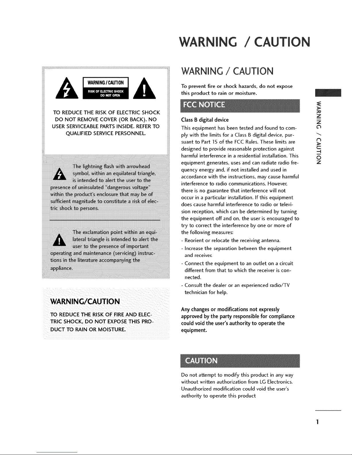
TO REDUCE THE RISK OF ELECTRIC SHOCK
DO NOT REMOVE COVER (OR BACK). NO
USER SERVICEABLE PARTS INSIDE, REFER TO
QUALIFIED SERVICE PERSONNEL
WARNING/CAUTION
TO REDUCE THE RISK OF FIRE AND ELEC-
TRIC SHOCK, DO NOT EXPOSE THIS PRO-
DUCT TO RAIN OR MOISTURE.
To prevent fire or shock hazards, do not expose
this product to rain or moisture.
Class B digital device
This equipment has been tested and found to com-
ply with the limits for a Class B digital device, pur-
suant to Part 15 of the FCC Rules. These limits are
designed to provide reasonable protection against
harmful interference in a residential installation. This
equipment generates, uses and can radiate radio fre-
quency energy and, if not installed and used in
accordance with the instructions, may cause harmful
interference to radio communications_ However,
there is no guarantee that interference will not
occur in a particular installation, if this equipment
does cause harmful interference to radio or te_evi_
sion reception, which can be determined by turning
the equipment off and on, the user is encouraged to
try to correct the interference by one or more of
the following measures:
- Reorient or relocate the receiving antenna.
Increase the separation between the equipment
and receiver.
Connect the equipment to an outlet on a circuit
different from that to which the receiver is con-
nected.
- Consult the dealer or an experienced radio_V
technician for help.
Any changes or modifications not expressly
approved by the party responsible for compliance
could void the user's author_ to operate the
equipment.
_>
Z
Z
C_
t_
_>
-4
O
Z
Do not attempt to modify this product in an,,,way
without written authorization from LG Electronics,
Unauthorized modification could void the user's
authority to operate this product
SAFETY INSTRUCTION
IMPORTANT SAFETYINSTRUCTIONS
Important safety instructions shall be provided with each apparatus. This information shall be given in a se-
parate booklet or sheet, or be located before any operating instructions in an instruction for installation for
use and supplied with the apparatus.
m
-4
-<
Z
-4
c
-4
0
Z
This information shall be given in a language acceptable to the country where the apparatus is intended to
be used.
The important safety instructions shall be entitled "Important Safety Instructions". The following safety
instructions shah be included where applicable, and, when used, shah be verbatim as follows. Additional safe-
ty information may be included by adding statements after the end of the following safety instruction hst. At
the manufactureFs option, a picture or drawing that illustrates the intent of a specific safety instruction may
be placed immediately adjacent to that safety instru_ion :
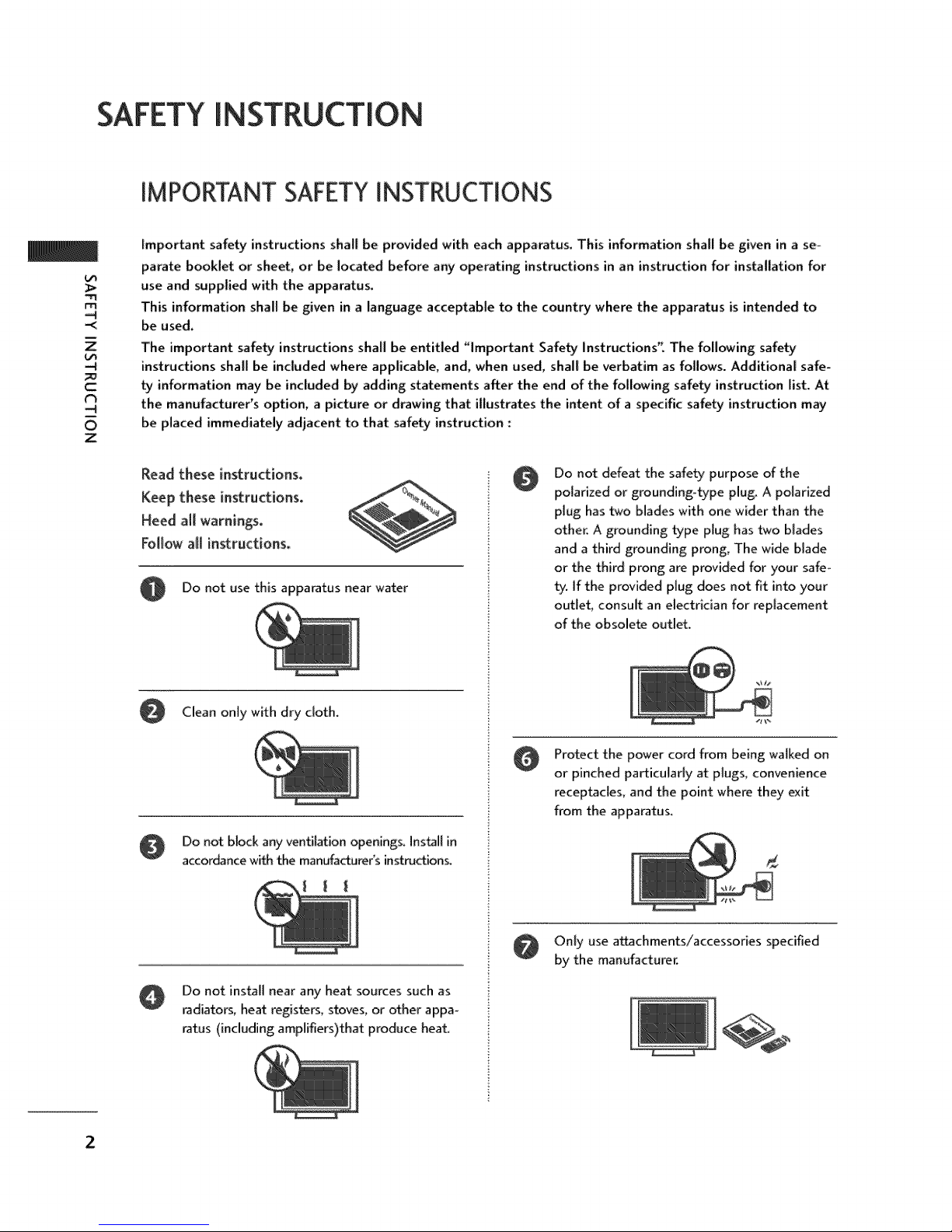
Read these instructions.
Keep these instructions.
Heed air warnings.
Follow a_l instructions.
0 Do not use this apparatus near water
Clean only with dry cloth,
Do not block any ventilation openings. Instil in
accor&3ncewith the manufacturer's instructions.
Do not defeat the safety purpose of the
0
polarized or grounding-type plug. A polarized
plug has two blades with one wider than the
other. A grounding type plug has two blades
and a third grounding prong, The wide blade
or the third prong are provided for your safe°
ty. if the provided plug does not fit into your
outlet consult an electrician for replacement
of the obsolete outlet.
Protect the power cord from being walked on
or pinched particularly at plugs, convenience
receptacles, and the point where they exit
from the apparatus,
Do not install near any heat sources such as
radiators, heat registers, stoves, or other appa-
ratus (including amplifiers)that produce heat,
2
Only use a_chments/accessories specified
by the manufacturer.
[
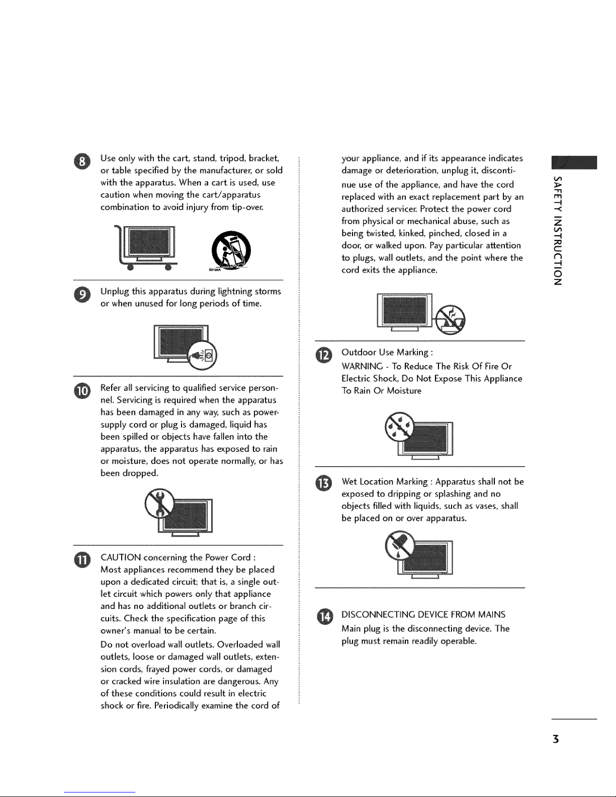
Use only with the cart_ stand, tripod, bracket,
or _ble specified by the manufacturer, or sold
with the apparatus. When a cart is used, use
caution when moving the cart/apparatus
combination to avoid injury from tip-over.
Unplug this apparatus during lightning storms
or when unused for long periods of time.
Refer all servicing to qualified service person-
@
nel. Servicing is required when the apparatus
has been damaged in any way_ such as power°
supply' cord or plug is damaged, liquid has
been spilled or objects have fallen into the
apparatus, the apparatus has exposed to rain
or moisture, does not operate normally, or has
been dropped.
your appliance_ and if its appearance indicates
damage or deterioration_ unplug if, disconti-
nue use of the appliance, and have the cord
replaced with an exact replacement part by an
authorized servicer. Protect the power cord
from physical or mechanical abuse, such as
being _isted, kinked, pinched, closed in a
door, or walked upon. Pay particular attention
to plugs, wall outlets, and the point where the
cord exits the appliance.
Outdoor Use Marking ::
@
WARNING - To Reduce The Risk Of Fire Or
Electric Shock, Do Not Expose This Appliance
To Rain Or Moisture
Wet Location Marking : Apparatus shall not be
exposed to dripping or splashing and no
objects filled with liquids, such as vases, shall
be placed on or over apparatus.
"rl
-<
Z
C=
t_
O
Z
CAUTION concerning the Power Cord :
Most appliances recommend they be placed
upon a dedicated circuit; that is, a single out-
let circuit which powers only that appliance
and has no additional outlets or branch cir-
cuits. Check the specification page of this
owner's manual to be certain.
Do not overload wall outlets. Overloaded wall
outlets, loose or damaged wall outlets, exten-
sion cords, frayed power cords, or damaged
or cracked wire insulation are dangerous. Any,
of these conditions cou(d result in electric
shock or fire. Periodically examine the cord of
DISCONNECTING DEVICE FROM MAINS
Main plug is the disconnecting device. The
plug must remain readily operable.
CONTENTS
WARNING / CAUTION ..................... 1
SAFETY INSTRUCTIONS 2-3
Input Label ..............................49
DTV SignalStrength......................50
TV Guide On ScreenTM Notices for U.SA/
N
O
Z
-4
r'rl
z
-4
Digital Cable CompatibiH_ ................ 6
FEATURES OF THIS TV ................... 7
Accessories .............................. 8
Fm,xlt & _ P_ InformatkJn..............IO-13
Attaching the TV to a Wall ................. 14
Back Cover for Wire Arrangement ........ 15-16
Desktop Pedestal Installation .............. 17
Antenna or Cable Connection .............. 18
CableCARD _1......................... 19-23
HD Receiver Setup .......................................24-26
DVD Setup .............................................27-28
VCR Setup................................................29-30
Other A]V Source Setup .................................31
PC Setup .................................................32-35
AV Out Setup .....................................................36
DigitalAudio Out Setup ..................................37
Setup of TV Guide On Screen_M......... 51-54
Functions of TV Guide On Screen r_z...... 55-73
-Overview ............................. 55
-Screen Components/Panel Menu ..... 56-57
-Listings ..............................58
-Search ........................... 59-62
_Recorded program fist ................ 63-64
-Schedule ............................. 65
-Change Setup ..................... 66-69
-Record ........................... 70-72
-Remind ............................ 73- 75
Timeshift ( Pause & Replay of Live TV) .... 76-78
Instant Recording ..................... 79-81
Programmed Recording ................... 82
Recorded TV Program List .............. 83-88
Format Hard Disc ........................ 89
Remote Control Functions .............. 38-39
Turning on TV ............................ 40
Channel Selection ........................... 41
Volume Adjustment ......................41
On-Screen Menus L1nguage Selection ....... 42
Channel Setup
°Auto Scan ( EZ Scan) ................... 43
- Add / Delete Channel ( Manual Scan) .... 44
-Channel Editing.......................45
Brief Info................................... 46
Input Source Selection ........................ 47
Auto Link ............................... 48
4
Watching PIP ( Picture-in-Picture)/
POP( Picture-out-of-Picture)/Twin Picture .90-93
Pid_ure Size (Aspect Ratio) Control .......... 94
Preset Picture Settings
-, EZ Picture o Preset .................... 95
- Adaptive Picture Mode (APM).......... 96
oControl Tone - Wa_ / _1. ............. 97
Man_l PicbJreAdjustment
- EZ Picture - User Mode .............. 98
oColor Tone - User Mode ............... 99
XO _ Picturetmprc_¢eme_Technolo_ ......... lO0

Advanced - Cinema 3:2 Pulldown Mode ..... 101
Advanced - Black(Darkness) Level ......... 102
Picture Reset ............................ 103
imageSfi<_r_ Minimization(ISM) M_l_xl ...... 104
Low-Power Picture Mode .................. 105
Auto Volume Leveler ( EZ SoundRite) ....... 106
Preset Sound Settings( EZ Sound) ......... ]07
Sound Setting Adjustment- User Mode .. 108-109
Balance ................................ 110
BBE - Sound Improvement Technolo_ ...... 111
Stereo / SAP Broadcast Setup .............. ]12
TV Speakers On/Off Setup ............... ]13
Audio Language ......................... ]14
On-Screen Menus Selection ............... ]15
Caption / Text ....................... ]16-117
Programming the Remote Control ..... 136-139
IR Codes............................ 140-141
External Control through RS-232C ..... 142-147
N
O
Z
-4
rrl
z
-4
Clock Setting ....................... 1!8-119
Auto On/Off Timer Setting ............... t20
Sleep Timer Setting ...................... 121
Auto Shut-off Setting .................... 122
Set Password & Lock System .......... 123-124
Channel Blocking ........................ 125
Movie & TV Rating .................. 126-128
External Input Blocking ................... 129
Troubleshooting ..................... 130-132
Maintenance ........................... 133
Product Specifications ....................... 134
5

INTRODUCTION
TV GUIDE ON SCREEWMNOTICES FORU.S.A.
Trademark Notice
In the United States, TV GUIDE and other related marks are registered marks of Gemstar-TV Guide
international, Inc. and/or one of 1% aMliates. In Canada, TV GUIDE is a registered mark of
Transcontinental Inc, and is used under license by Gemstar-TV Guide International Inc.
m
z
--4
O
C
--4
O
z
License Notice
The TV Guide On Screen 1Msystem is manufactured under license from Gemstar=TV Guide
International, Inc. and/or one of its affiliates.
Patent Notice
The TV Guide On Screen"_ system is protected by one or more of the following issued United
States patents 6,498,895_ 6,41&556, 6,331,877; 6,239,794; 6,154,203; 5,940,073; 4,908,713;
4,75] ,578; 4,706,121.
Use of the CableCARD !_ TradeMark.
_CableCARD rM is a trademark of Cable Television Laboratories, Inc."
DIGITAL CABLECOMPATIBILITY
This digital television is capable of receiving basic analog, digital basic and digital premium cable
television programming by direct connection to a cable system providing such programming. A
security card provided by your cable operator is required to view encrypted digital programming.
Cable operator enhanced program (For example, electronic program guide provided by the cable
operator), and data enhanced television service may require the use of a set top box. For more
information contact your local cable operator_
II [il"_'l!lJ t._]!1J[_!:| II
OffMal term for an HDTV that con[om_s to the plug-
and,play digital cable TV s_ndard using POD (Point
of _p[oyment) access cards_also cal[_
Cab[eCARDs, t|_t allow u_rs to plug the cable
directly into an HDTV set and enjoy HDTV and digi-
tal cable without having to use a separate set-top
bow
is a trade_rk of SRS Labs, Eric.
°ffuSurround XT technology is incorporated under
licen_ from SRS Labs, Inc.
DIGITAL
Manufa_ured under license from Do[_ Laboratories
_'Dolby _and tl'_edoub[e-D syml_[ are trademarks of
Dolby Laboratori_
High definition te[e,Asion_HighoresoIutkan digital
_evision broadcast and playback systern composed
of roughly a million or more pixeIs, 16:9 as_cbratio
_r_ns, and AC3 digitai audio_ A subset of digital
televisbn, HDTV formats include ]08Oi and 720p
re_lutions.
Manufactured under license from BBE Sound, I_ci
A Digital Video Recorder (DVR) is adevice that
empowers you to control wl_atyou watch, when you
watch JLIt allows you to store ar_t access TV pro_
grams functioning like a VCK but Mtb no video
_. With a DVR, you can a&o pau_ live TV and
choose the shows you want to _ord through an
electronic program guide,
6
HDmr
HDMI;% t}_ HDM_ logo and Higfl-Definition
Multimedia ln_rface are trademarks or registered
trademarks of HDMI Licensing."
LG's own sp_l digital i_ge generator, consisting
Of a fiJ][ digital image pro_essor, APM m_e & six dif-
ferent main picture quality factors.
FEATURESOF THIS TV
What is a Plasma TV ?
Using plasma is the best way to achieve nat panel
displays with excellent image quality and large screen
sizes that are easily viewable_ The Plasma TV can be
thought of as a descendant of the neon lamp and or
a series of fluorescent lamps.
How does it work?
PlasmaTV is an array of cells, known as pixels, which
are comprised of three sub-pixels, corresponding to
the colors red, green, and blue. Gas in a plasma state
is used to react with phosphors in each sub-pixel to
produce colored light (red, green, or blue). These
phosphors are the same types used in Cathode Ray
Tube (CRT) devices such as televisions and common
computer monitors.
PlasmaTV offers a rich, dynamic display because
each sub_pixel is individually controlled by advanced
electronics to produce over 16 million different cob
ors. This means that you get perfect images that are
easily viewable in a display that is fewer than five
inches thick_
160 - Wide angle range of vision
Your fiat panel plasma screen offers an exceptionally
broad viewing angle of over 160 degrees. This means
that the display is clear and visible to viewers any-
where in the room,
Wide Screen
The wide screen offers a theater-like experience in
your own home.
Multimedia
Connect your plasma display to a PC and use it for
conferencing, games, and [nternet browsing. The
Picture-in-Picture feature allows you to view your PC
and video images simultaneously.
cells. A few cell defects will normally occur in the
Plasma TV manufacturing process. Several tiny,
minute colored dots visible on the screen should be
acceptable. This also occurs in other Plasma TV
manufacture_' products. The tiny dots appearing
does not mean that this Plasma TV is defective. Thus
a few cell defects are not sufficient cause for the
Plasma TV to be exchanged or returned. Our pro-
duction technology minimizes these cell defects dur-
ing the manufacture and operation of this product.
Cooling Fan Noise
In the same way that a fan is used in a PC computer
to keep the CPU (Cent_l Processing Unit) cool, the
Plasma TV is equipped with cooling fans to cool the
Monitor and improve its reliability. Therefore, a cer-
tain level of noise could occur while the fans are
operating and cooling the Plasma TV.
The fan noise doesn't have any negative effect on
the Plasma TV's efficiency or reliability. The noise
from these fans is normal during the operation of
this product. We hope you understand that a certain
level of noise from the cooling fans is acceptable and
is not sufficient cause for the Plasma TV to be
exchanged or returned.
FOR LCD TV
If the TV feels cold to the touch, there may be a
smaff "flicker" when it is turned on. This is normal,
there is nothing wrong with TV.
Some minute dot defects may be visible on the
screen, appearing as tiny red, green, or blue spots.
However, they have no adverse effect on the monio
torts performance.
Avoid touching the LCD screen or holding your fin-
ger(s) against it for long periods of time. Doing so
may produce some temporary distortion effects on
the screen.
i
0
Z
Versatile
The light weight and thin size makes it easy to install
your plasma display in a variety of locations where
conventional TVs do not fiL
The Plasma TV Manufacturing Process: a few
minute colored dots may be present on the
Plasma TV screen
The Plasma TV is composed of 0.9 to 2.2 million
On O_s,_l
a. The fluorescent lamp used in this product con-
tains a small amount of mercury.
b. Do not dispose of this product with general
household waste.
a Disposal of this product must be carried out in
accordance to the regulations of your local
authority.
7
512Eenl 80/11/24 4:54 PH Page 8
PREPARATION
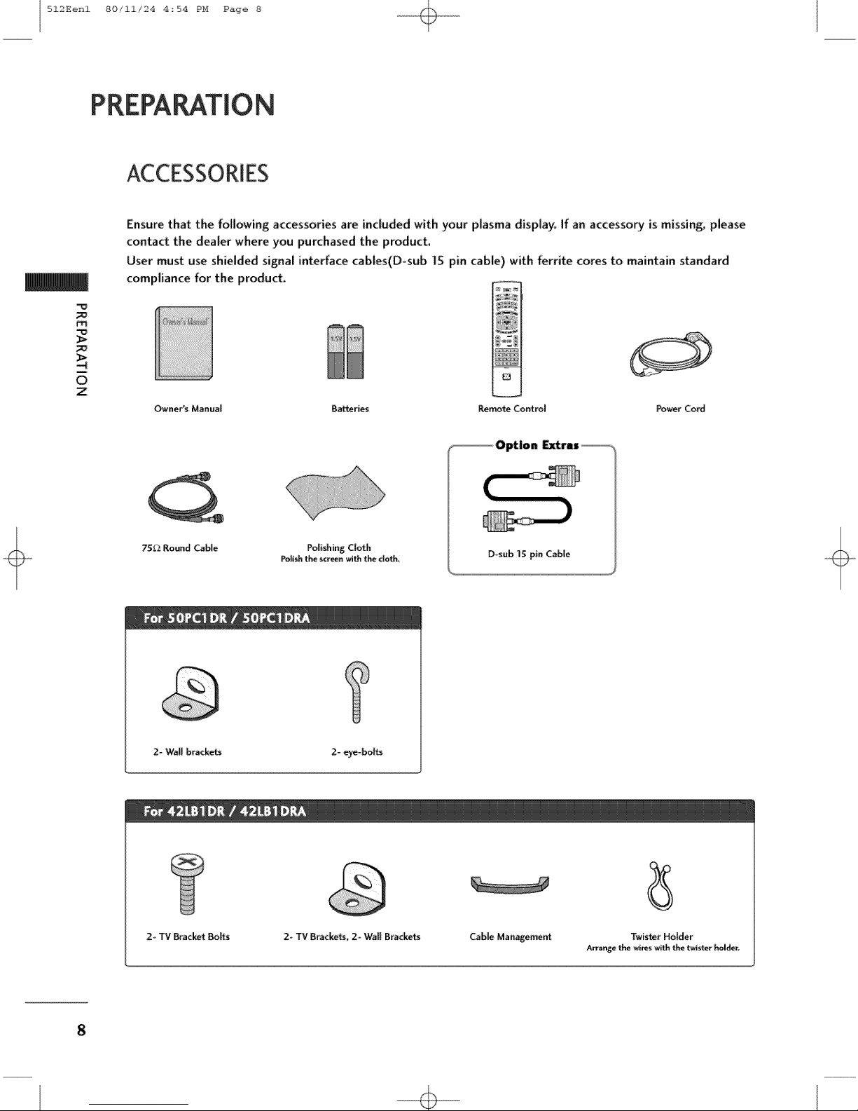
ACCESSORIES
Ensure that the following accessories are included with your plasma display. If an accessory is missing, please
contact the dealer where you purchased the product.
User must use shielded signal interface cables(D-sub IS pin cable) with ferrite cores to maintain standard
compliance for the product.
m
i
0
Z
Owner's M_nual B_ries Remorse Control Power Cord
75_ Round CalVe
2- Wall brackets 2- eye-bo_
Polishing Cloth
Poff_ the _reen with tl'_ do_.
E
D_sub1Spin Cab|e
2-TV _acket Bolts
2- TV Bracke_, 2- Wall Brackets
8
Cable Management
Arrange _ _r_ with _ twiste_ holder.
TwisterHolder

512Eenl 80/11/24 4_54 PH Page 9
HOME MENU
This menu is a contents guide.
In HOME Menu, you can enter the recorded list of DVR, TV Guide,
Schedule of the TV Guider Manual Record of DVR or TV Menu.
i
0
z
I_¢ Guide
DVR
p.76
9

512Eenl 80/ii/24 4_54 PH Page i0
FRONT & BACK PANELINFORMATION
This is a representation of the front panel of models 5OPCT DR, 50PC] DRA series TVs.
Here shown may be somewhat different from your TV.
Front Panel Controls
m
i
0
z
Remote
Control Sensor
Power Standby Indicator
Illuminates redin standby
mode.
When the TV is turned
on, the indicator blinks
white and then illumi-
nates white before the
picture is displayed.
10
VOLUME CHANNEL
512Eenl 80/11/24 4_54 PH Page ii
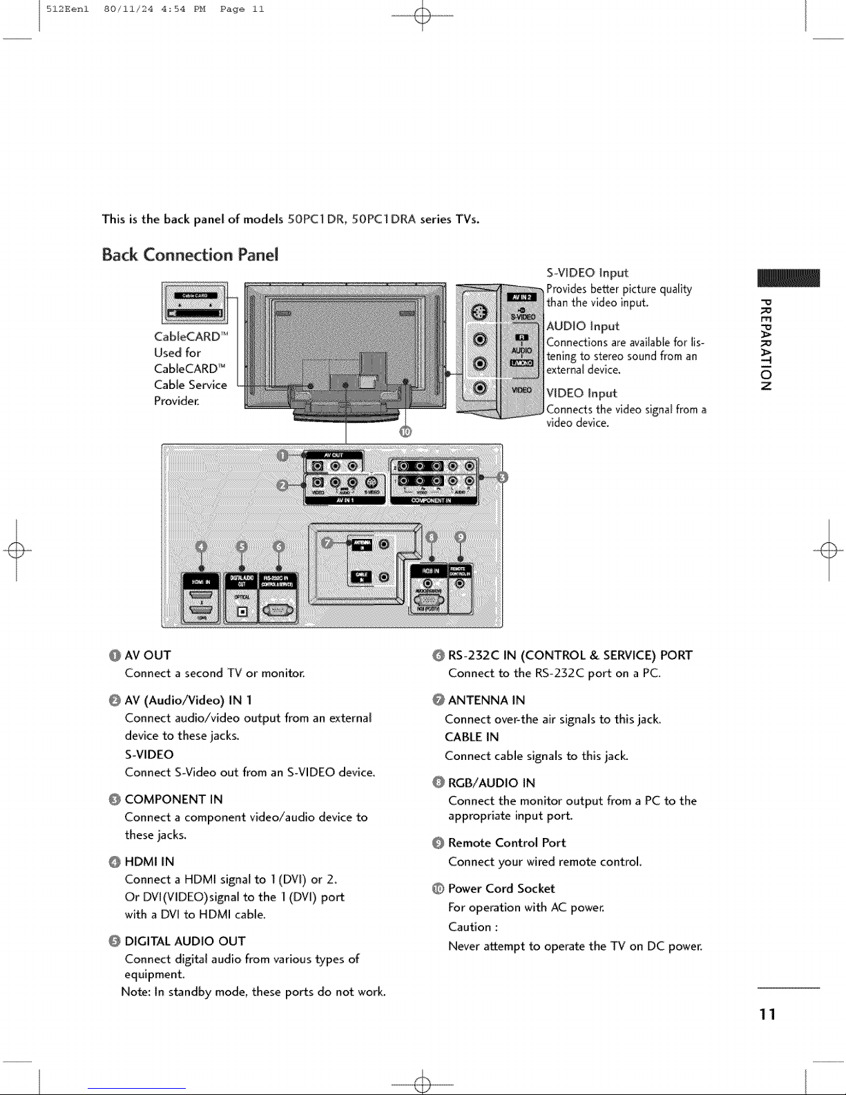
This is the back panel of models 50PC] DR, 50PC] DRA series TVs.
Back Connection Panel
CabJeCARD _-€
Used for
CabIeCARD _
Cable Service
Provider.
S-VIDEO Input
Provides better picture qua[fly
than the video input.
AUDIO input
Connections are available for lis
tening to stereo sound from an
external device,
VIDEO Input
Connects the video signal from a
video device,
m_
O
z
@ AV OUT
Connect a second TV or monitor.
@
AV (Audio/Video) IN I
Connect audio/video output from an external
device to these jacks.
S-VIDEO
Connect S-Video out from an SWIDEO device.
@ COMPONENT IN
Connect a component video/audio device to
these jacks,
@ HDMI IN
Connect a HDMI signal to 1(DV[) or 2,
Or DVt(VlDEO)signal to the 1 (DVI) port
with a DVl to HDMI cable.
@ DIGITAL AUDIO OUT
Connect digial audio from various types of
equipment.
Note: In standby mode, these ports do not work.
@ RS-232C IN (CONTROL & SERVICE) PORT
Connect to the RS-232C port on a PC.
@ ANTENNA IN
Connect over-the air signals to this jack
CABLE IN
Connect cable signals to this jack.
@ RGB/AUDIO IN
Connect the monitor output from a PC to the
appropriate input port.
@ Remote Control Port
Connect your wired remote control.
Power Cord Socket
For operation with AC power.
Caution :
Never attempt to operate the TV on DC power.
11
+

512Eenl 80/ii/24 4:54 PH Page 12
FRONT & BACK PANELINFORMATION
This is a representation of the front panel of models 42LB1 DR, 42LB] D_ series TVs.
Here shown may be somewhat different from your TV.
Front Panel Controls
m
0
Z
12
TV
POWER GUIDE INPUT MENU
VOLUME CHANNEL
Button Button Button Button
Power Standby Indicator
Illuminates red in standby mode.
When the TV is turned on, the indicator
Remote Control Sensor blinks white and then illuminates white
before the picture is displayed_
INDEX
Digital Cable Ready
HDTV mode
HDMI]/DVI or HDMI2 mode
Recording
Setting the reserve record
Operating the TimeShift
512Eenl 80/11/24 4_54 PH Page 13
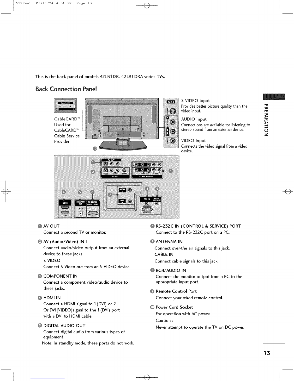
This is the back panel of models 42LB1 DR_ 42LB] DRA series 1-Vs.
Back Connection Panel
CableCARD _
Used for
CableCARD _
Cable Service
Provider
S_VIDEO input
Provides better picture quality than the
video input.
AUDIO Input
Connections are available for listening to
stereo sound from an external device,
VIDEO Input
Connects the video signal from a video
device.
m_
O
Z
@ AM OUT
Connect a second TV or monitor_
@
AV (Audio/Video) IN I
Connect audio/video output from an external
device to these jacks.
S-VIDEO
Connect S-Video out from an S_VIDEO device.
@
COMPONENT IN
Connect a component video/audio device to
these jacks.
HDMI IN
@
Connect a HDMI signal to ](DVi) or 2.
Or DVl(VlDEO)signal to the 1 (DVl) port
with a DVI to HDMI cable.
O DIGITAL AUDIO OUT
Connect digital audio from various types of
equipment.
Note: In standby mode, these ports do not work_
RS°232C IN (CONTROL & SERVICE) PORT
Connect to the RSo232C port on a PC.
@ ANTENNA IN
Connect over-the air signals to this jack
CABLE IN
Connect cable signals to this jack_
RGB/AUDIO IN
Connect the monitor output from a PC to the
appropriate input port.
Remote Control Port
Connect your wired remote control.
O Power Cord Socket
For operation with AC power,
Caution :
Never attempt to operate the TV on DC power.
13

512Eenl 80/11/24 4_54 PH Page 14
ATTACHING THE TV TO A WALL
We recommend that you set up the IV close to a wall so it cannot fail over if pushed backwards
Additionally, we recommend that the TV be attached to a wait so it cannot be pulled in a forward direction, poten-
tially causing injury or damaging the product.
Caution: Please make sure that children don't climb on or hang from the TV.
m
0
z
50PC] DR !50PC] DRA 42LB] DR/42LB] DRA
insert the eye-botts (or TV brackets and boffs) to tighten the product to the wail as shown in the picture.
*lnse_ the eye-botts and tighten them securely in the upper hobs,
Secure the walt b_ckets with the bolts (not provided as parts of the product, must purchase separately ) on
the wail. Match the height of the bracket that is mounted on the wall to the holes in the product_
Ensurethe eye-bolts or brackets are tightened securely
Use a sturdy rope (not provided as parts of the product, must purchase sepa_
rarely) to tie the product. It is safer to tie the rope so it becomes hor{zonta[
between the walt and the product.
14

512Eenl 80/11/24 4_54 PH Page 15
BACKCOVERFORWIRE ARRANGEMENT
50PC] DR/5:0PCI DRA
O Hold the CABLE MANAGEMENT with both hands and pull it backward as shown.
O
Z
as
Connect the cables
To connect an additional equipment, see the External equipment Connections section.
g Instil the CABLE MANAGEMENT as shown.
necessary.
1S
512Eenl 80/11/24 4:54 PH Page 16
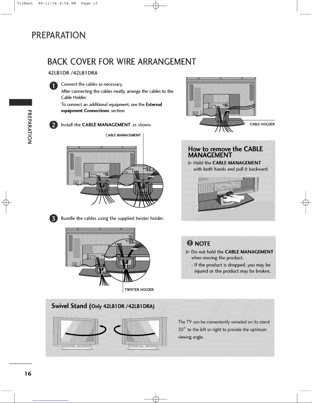
BACK COVERFOR"WIREARRANGEMENT
42LB1 DR/42LB1 DRA
Connect the cables as necessary.
@
A_er connecting the cables neatl)¢ arrange the cables to _e
Cable Holder.
To connect an additional equipment, see the External
equipment Connections section.
m
Install the CABLE MANAGEMENT as shown.
O
i
O
Z
CABLE MANAGEMENT
Bundle the cables using the supplied twister holder.
TWISTER HOLD_
16

512Eenl 80/11/24 4_54 PH Page 17
,iiiThis manual explains the features available on the 50PC] DR, 50PC] DRA seriesTVs.
c Here shown may be somewhat different from your TV.
Short-circuit Brecker
Ensure that you connect the earth ground wire to prevent possible electric shock. If grounding methods
are not possible, have a qualified electrician instals a separate circuit breaker.
Do not try to ground the unit by connecting it to telephone wires, lightening rods, or gas pipes.
DESKTOPPEDESTALINSTALLATION
For proper ventilation, allow a clearance of 4 in. on each side and the top, 2.36 in. on the bottom, and 4 in.
from the wall.
50PC] DR/50PC] D_
4 i_ches
0
z
4.inches 4 inch_ 4 inches 4 inches 4 _nches
4 inch_
17

512Eenl 80/11/24 4:54 PH Page 18
ANTENNA OR CABLECONNECTION
1. Antenna (analog or digital)
Wall Antenna Socket or Outdoor Antenna without a Cable Box
Connections. For optimum picture quality, adjust antenna direction
if needed.
m
i
O
z
Outdo RF Coaxial Wire (75 ohm)
Antenna ...........................................................................................................................
(VHF, UH[) / Single-family Dwellings/Houses
]
(Conn_t to wall jack for outdoor antenna)
Bronze W_re ]
Be careful not to _nd the bronze
wire when connecting the antenna.
2. Cable
Cable TV
Wall jack
3. Using both cable and antenna
Antenna
RF Coaxial Wire (75 ohm)
18
512Eenl 80/11/24 4_54 PH Page 19
ANtenn ,,
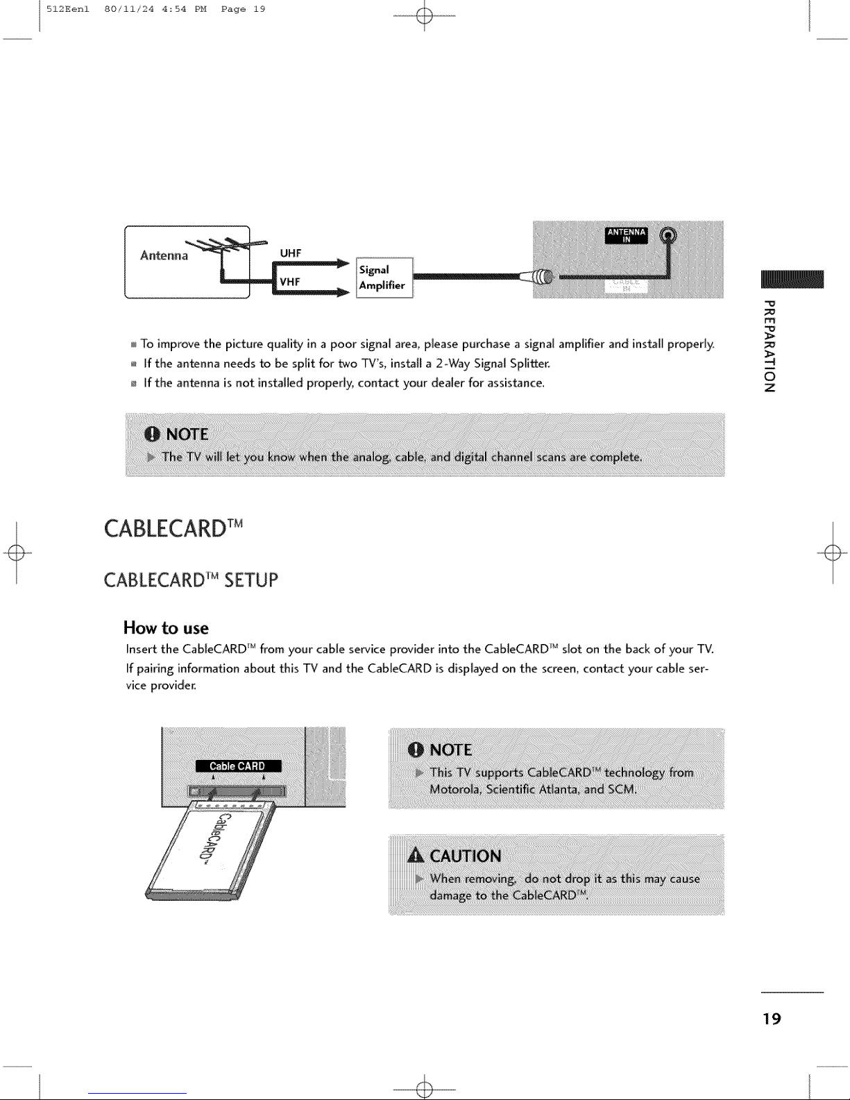
To improve the picture quality in a poor signal area, please purchase a signal amplifier and install properly,
If the antenna needs to be split for two TV's, install a 2-Way Signal Splitter.
If the antenna is not installed properly, contact your dealer for assistance.
m_
O
Z
CABLECARDTM
CABLECARD_MSETUP
How to use
Insert the CaBleCARD _Mfrom your cable service provider into the CableCARD 'u slot on the back of your TV.
If pairing information about this TV and the CableCARD is displayed on the screen, contact your cable ser-
vice provider.
19
512Eenl 80/11/24 4_54 PH Page 20
CableCARD TM FUNCTION
In this m_nuat, the OSD (On Scn,;enDisplay) m_y be di;ff_ren[from your TV'sb(_c_us_<it isjust
e_ampl_: _o h_Ip th{ _¢operation.
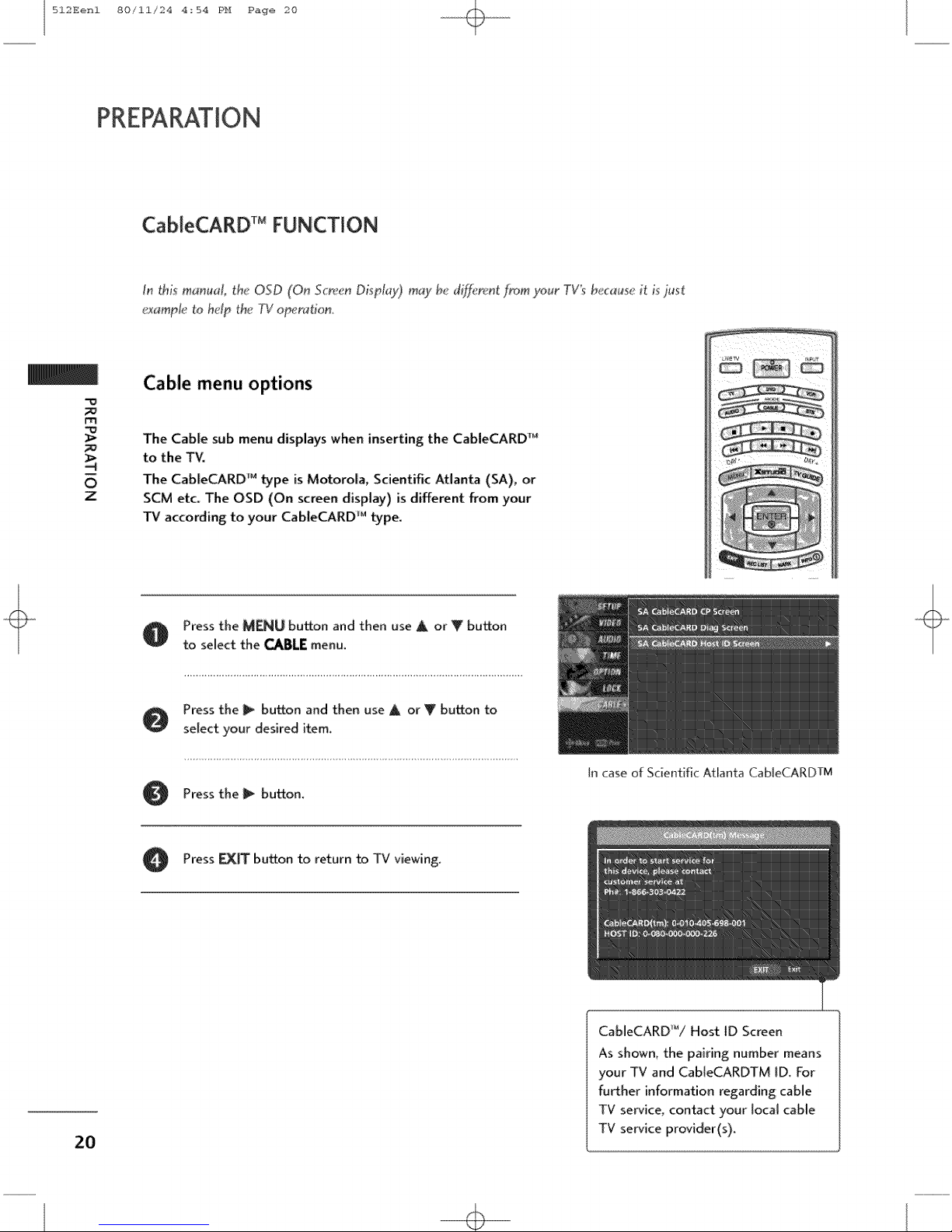
Cable menu options
m
The Cable sub menu displays when inserting the CableCARD _
to the TV.
0
Z
The CableCARD _ type is Motorola, Scientific Atlanta (SA), or
SCM etc_ The OSD (On screen display) is different from your
TV according to your CabteCARD _Mtype.
2O
O Press the MENU button and then use A or Y button
to select the CABLEmenu.
Press the _ button and then use A or Y button to
select your desired item.
Pressthe _ button.
Press _ button to return to TV viewing.
In case of Scientific Atlanta CableCARDTM
CableCARD'_/Host ID Screen
As shown, the pairing number means
your TV and Cab[eCARDTM ID. For
fu_her information regarding: cable
TV service, contact your local cable
TV service provider(s).
512Eenl 80/11/24 4_54 PH Page 21
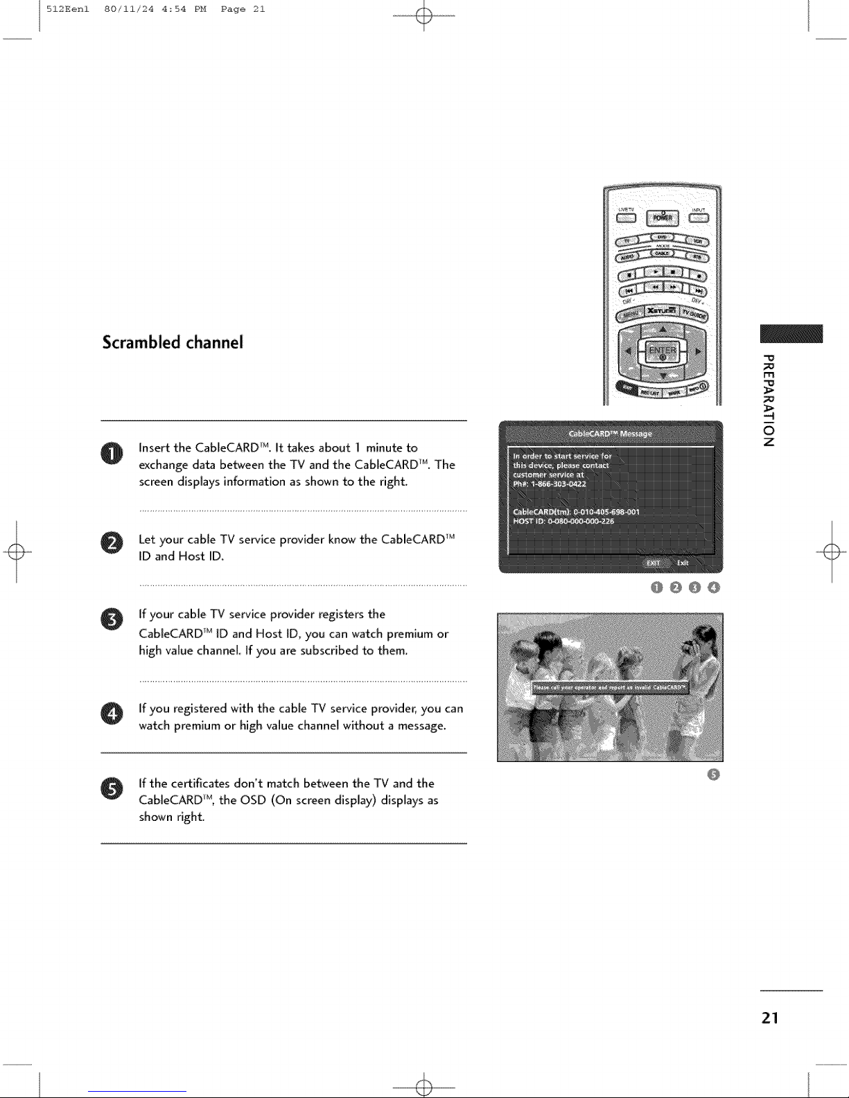
Scrambled channel
rTl
O Insert the CableCARD _M.It takes about 1 minute to
exchange data between the TV and the CabIeCARD_r'<The
screen dispIays information as shownto the right.
Let your cable TV service provider know the CableCARD _1
ID and Host ID.
O f your cable TV serviceprovider registers the
Cab[eCARD r_ tD and Host [D, you can watch premium or
high value channel. If you are subscribed to them.
O if you registered with the cable TV serviceprovider, you can
watch premium or high value channel without a message.
g If the certificates don't match between the TV and the
CableCARD _, the OSD (On screen display) displays as
shown right
@ @ @ @
m
0
z
21
512Eenl 80/11/24 4_54 PH Page 22
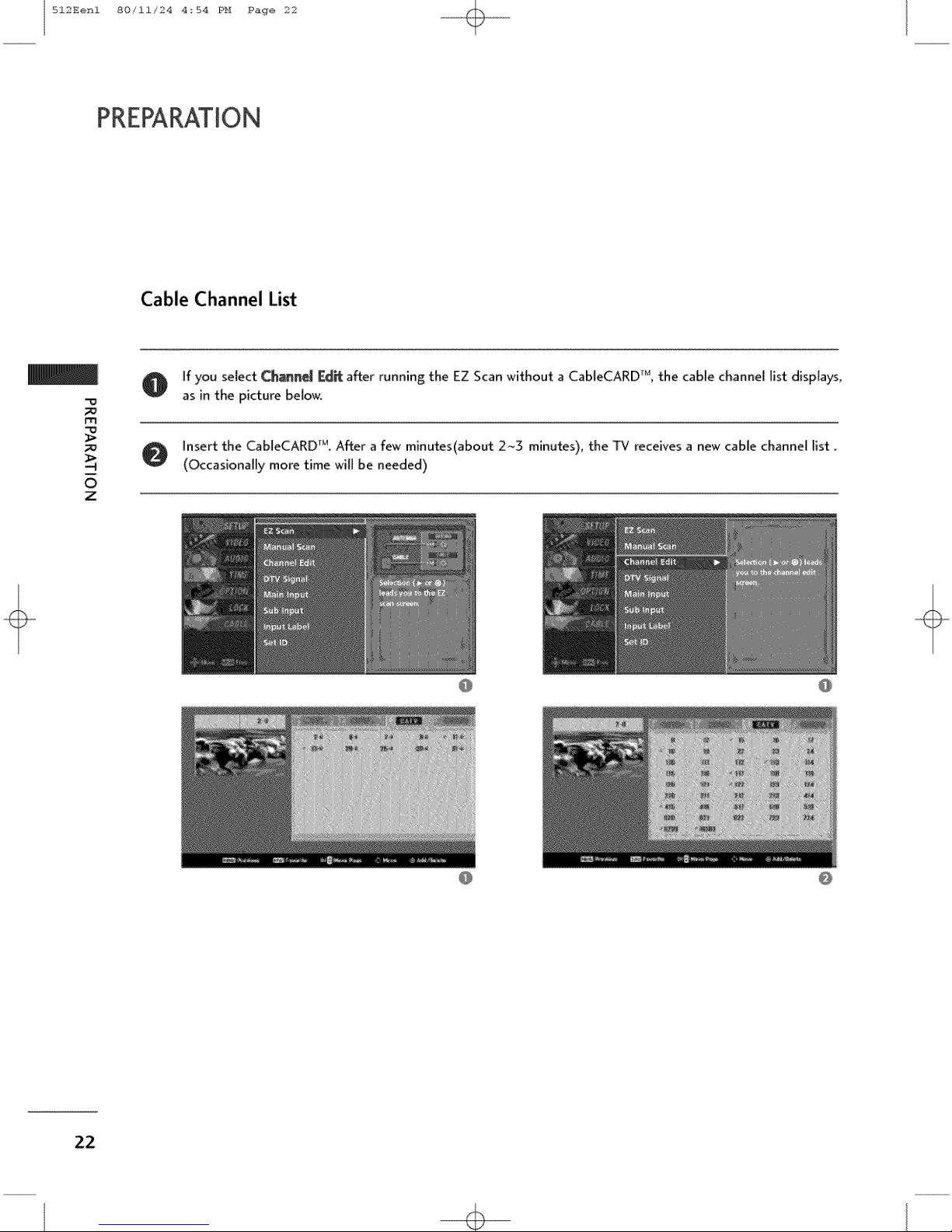
Cable Channel List
O f you select Chine[ [Zd_ after running the EZ Scan without a CableCARD _, the cable channel list displays,
"0
m
0
Z
as in the picture below.
O insert the CableCARD r_. After a few minutes(about 2~3 minutes), the TV receives a new cable channel list.
(Occasionally more time will be needed)
22
512Eenl 80/11/24 4_54 PH Page 23
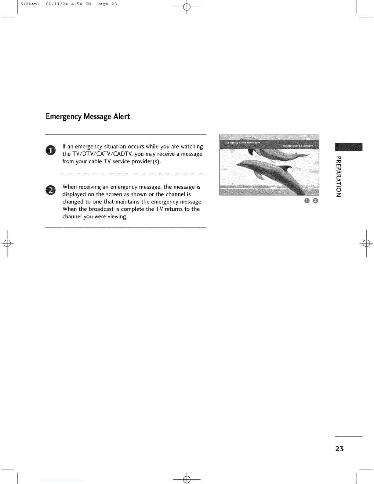
Emergency Message Alert
If an emergency situation occurs while you are watching
O
the TV/DTV/CATV/CADTV, you may receive a message
from your cable TV service provider(s).
m
When receiving an emergency message, the message is
0
displayed on the screen as shown or the channel Ns
changed to one that maintains the emergency message.
When the broadcast is complete the TV returns to the
channel you were viewing.
@ @
m
0
z
23
512Eenl 80/11/24 4_54 PH Page 24
EXTERNAL EQUIPMENT SETUP
HD RECEIVERSETUP
This TV can receive Digital Over-the_air/Cable signals without an external digital set-top box. However, if you
do receive digital signals from a digital set-top box or other digital external device, refer to the figure as
shown below.
This TV supports HDCP (Highobandwidth Digital Contents Protection) protocol for Digital Contents
(480p,720p,10801).
When connecting Component cable
m
X
/D
-4
M
Z
t-r{
c
m
Z
c
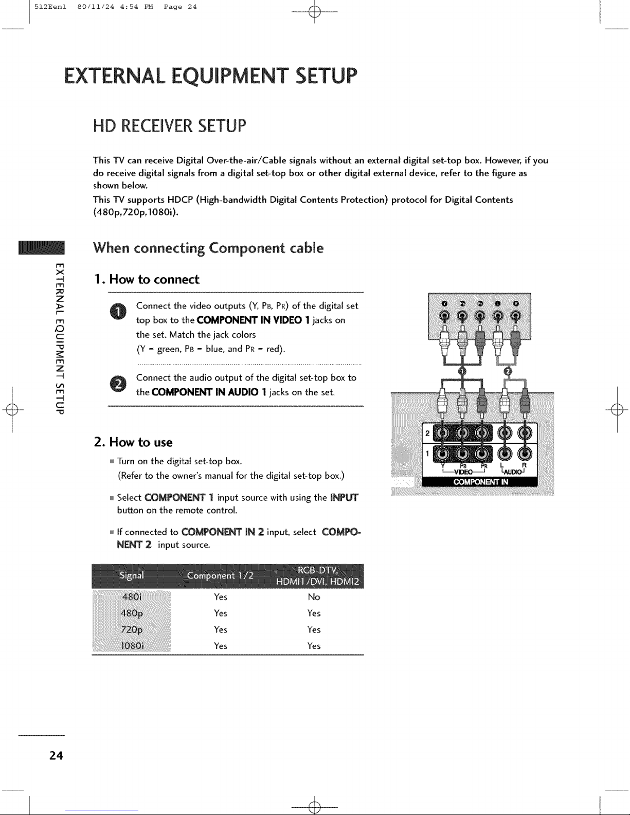
1. How to conne_
Connect the video outputs ('_; PB, PR) of the digital set
top box to the COMPON_T IN VIDEO I iacks on
the set. Match the jack colors
(Y _ greem Pa _ blue, and PR _ red).
O Connect the audio output of the digital set-top box to
the COMPONI_I°r IN AUDIO i jacks on the set.
m
2. How to use
Turn on the digital set-top box.
(Refer to the owner's manual for the digital set-top box.)
Select COMPONE_ 1 input source with using the INPUT
bu_on on the remo_ control.
If connected to COMPONF.NTIN 2 input, select COMPO_
N[NT 2 input source.
Yes No
Yes Yes
Yes Yes
Yes Yes
24
512Eenl 80/11/24 4_54 PH Page 25
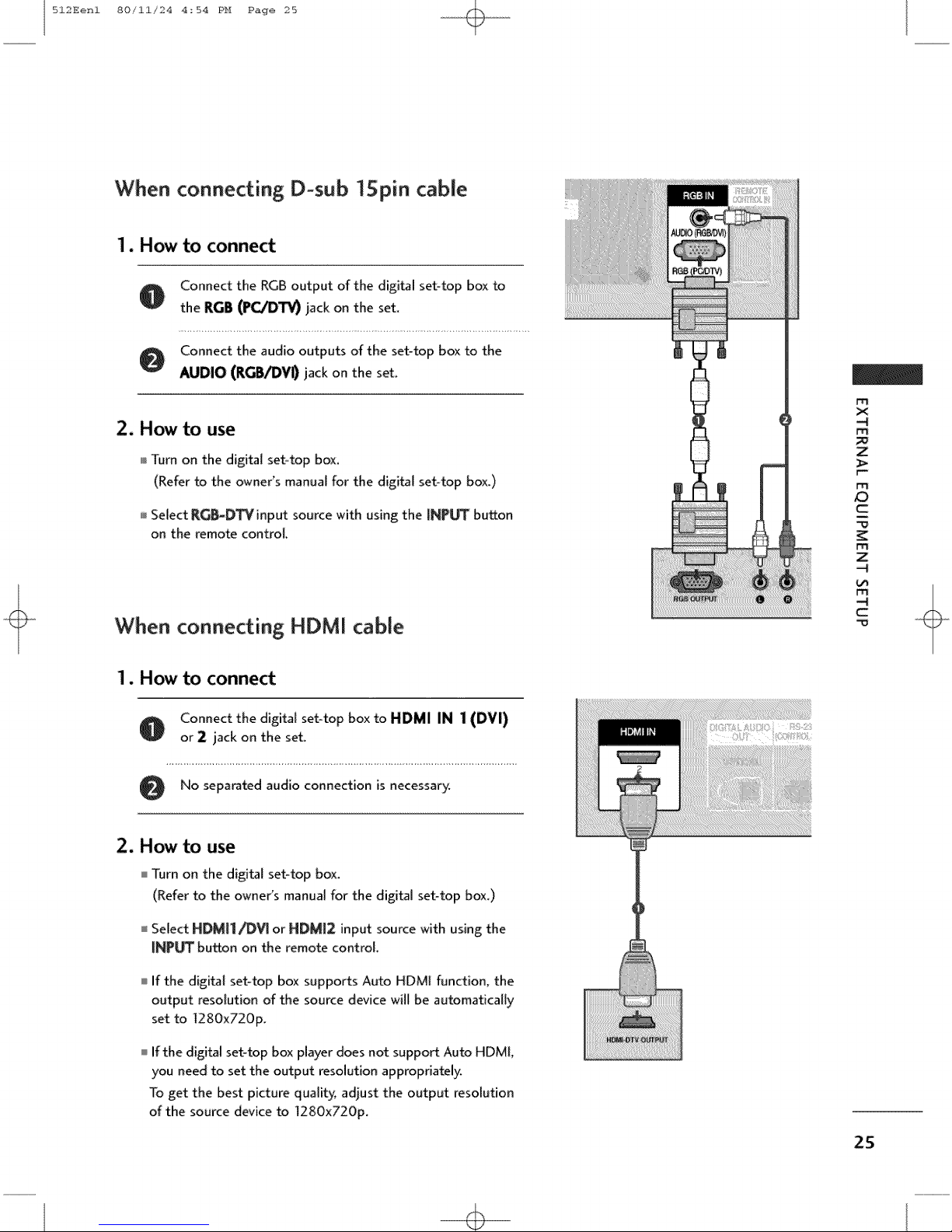
When connecting D-sub "15pin cable
1. How to connect
Connect the RGB output of the digital set-top box to
0
the RGB (PC/DTV} jack on the set.
Connect the audio outputs of the set-top box to the
0
AUDIO (RGB/DV0 jack on the set.
2. How to use
Turn on the digital set-top box.
(Refer to the owne{s manual for the digital set-top box.)
Select R_-D_input source with using the INP_ button
on the remote control.
m
x
m
Z
F-
ro
c
m
Z
When connecting HDMI cable
1. How to connect
O onnect the digital set-top box to HDMI IN 1 (DVI)
or 2 jack on the set.
No separated audio connection is
2. How to use
Turn on the digital set-top box.
(Refer to the owner's manual for the digital set-top box.)
I Select HDM[I/_V[ or NDM12 input source with using the
iNPUT button on the remote control.
If the digital set-top box supports Auto HDMI function, the
output resolution of the source device will be automatically
set to 1280x720p.
If the digital set-top box player does not support Auto HDMI,
you need to set the output resolution appropriately.
To get the best picture quality, adjust the output resolution
of the source device to 1280x720p_
necessary.
c
m
25
512Eenl 80/11/24 4_54 PH Page 26
EXTERNALEQUIPMENT SETUP
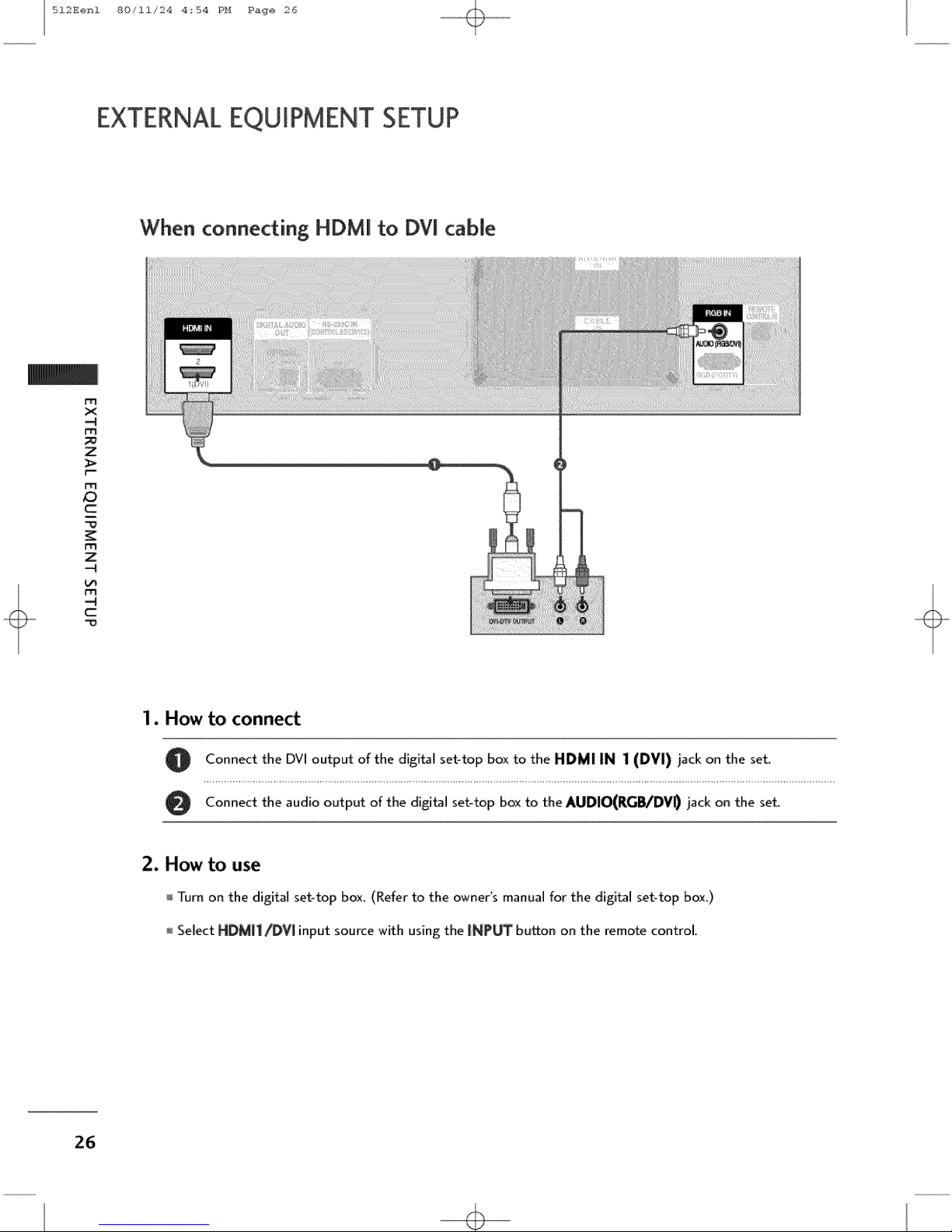
When connecting HDMI to DVI cable
m
X
-4
M
Z
m
c
m
Z
-4
!..rl
-4
C
m
1. How to connect
2. How to use
O Connect the DVI output of the digital set-top box to the HDMI IN 1 (DVI) jack on the set.
Connect the audio output of the digital set-top box to the AUDIO(RG_/DVID jack on the set.
Turn on the digital set-top box. (Refer to the owner's manual for the digital set-top box.)
Select HDMII_V[ input source with using the INPUT bu_on on the remote control,
26

512Eenl 80/11/24 4_54 PH Page 27
DVD SETUP
When connecting Component cable
to connect
Connect the video outputs (Y, P& PR) of the DVD to
the COMPONENT IN VIDEOll jacks on the set
Match the iack colors
(Y = green, PB = blue, and PR= red).
Connect the audio outputs of the DVD to the
0
COMPONENT IN AUDIO1 iacks on the set.
2. How to use
]_drn on the DVD player, insert a DVD.
Select COMPONENT 1 input source with using the
[NPb_ button on the remote control.
if connected to COMPONENT IN 2 input, sebct CO_
PONE_ 2.input source.
Refer to the DVD player's manual for operating instruc-
tions_
m
x
m
Z
r_
m
Z3
c
m
z
c
m
Component Input ports
To get better picture quality; connect a DVD player to the component input ports as shown below.
Component ports on
Video output ports
on DVD player
the TV
27
512Eenl 80/ii/24 4:54 PH Page 28
EXTERNALEQUIPMENT SETUP
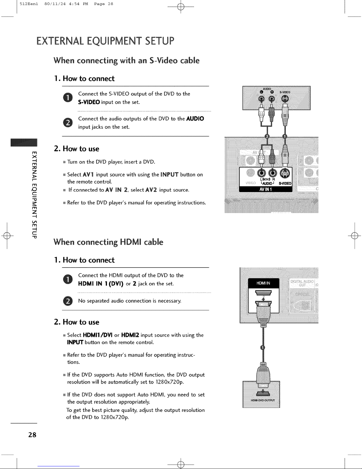
When connecting with an S-Video cable
1. How to connect
A Connect the S-VIDEO output of the DVD to the
S-VIDEO input on the set.
Connect the audio outputs of the DVD to the AUDIO
input jacks on the set.
m
X
-4
M
Z
m
/D
c
m
Z
-4
-4
C
m
When connecting HDMI cable
2. How to use
Turn on the DVD player, insert a DVD.
Select AV1 input source with using the INPUT button on
the remote control.
If connected to AV IN 2, select AV2 input source.
Refer to the DVD player's manual for operating instructions.
1. How to connect
O Connect the HDM[ output of the DVD to the
HDMI IN 1(DVI) or 2 iack on the set.
O No separated audio connection is necessary.
2. How to use
Select HDMI1/DVI or HDMI2 input source with using the
INPUT button on the remote control.
Refer to the DVD player's manual for operating instruc-
tions.
If the DVD supports Auto HDMI function, the DVD output
resolution wil! be au_matica![y set to ]280x720p.
If the DVD does not support Auto HDMI, you need to set
the output resolution appropriately.
To get the best picture quality, adjust the output resolution
of the DVD to 1280x720p,
28

512Eenl 80/11/24 4:54 PH Page 29
VCR SETUP
To avoid picture noise (interference), leave an adequate distance between the VCR and TV
Use the ISM feature in the Option menu to avoid having a fixed image remain on the screen for a long pew
riod of timer If the 4:3 picture format is used; the fixed images on the sides of the screen may remain visible
on the screen.
When connecting with an antenna
m
x
m
Z
r_
m
c
WallJack
Antenna
1. How to connect
O onnect the RF antenna out socket of the VCR to the Antenna socket on the set.
Connect the antenna cable to the RF antenna in socket of the VCR.
2. How to use
Set VCR output switch to 3 or 4 and then tune TV to the same channel number.
Insert a video t_pe into the VCR and press PLAY on the VCR. (Refer to the VCR owner's manual.)
m
Z
c
m
29
 Loading...