

Page 1
Lifds Good
LCD TV
OWNER'S MANUAL
32LG700H
37LG700H
42LG700H
Installer Reference for Commercial Mode
MPI/PPV Card Setup see page 19
Commercial Mode Setup see pages 85-107
Please read this manual carefully before operating
your set.
Retain it for future reference.
Record model hum
See the
tl dealer
service.
of the set.
:k cover and quote
leh
Serial:
This product qualifies for ENERGYSTAR in the "factory
default" setting and this is the setting in which power savings
will be achieved.
Changing the factory default picture setting or enabling other
features will increasepower consumption that could exceed
the limits necessary to quality for EnergyStar rating.
1-800-243-0000 usA_c_s_m__us_,
1-888-865-3026 usA__:_mm_oda_us__
1-888-542-2623 C,_NADA
P/NO : SAC30708043 (0902-REV03)
Page 2
WARNING / CAUTION
WARNING/ CAUTION
To prevent fire or shock hazards, do not expose
this product to rain or moisture.
WARNING/CAUTION
TO REDUCE THE RISK OF FIREAND ELECTRIC
SHOCK. DO NOT EXPOSE THIS PRODUCT TO
RAIN OR MOISTURE.
This reminder is provided to call the CATV system
installer's attention to Article 820-40 of the National
Electric Code (U.S.A.). The code provides guidelines for
proper grounding and, in particular, specifies that the
cable ground shall be connected to the grounding system
of the building, as close to the point of the cable entry
as practical.
Class B digital device
This equipment has been tested and found to comply
with the limits for a Class B digital device, pursuant to
Part 15 of the FCC Rules. These limits are designed
to provide reasonable protection against harmful
interference in a residential installation. This equipment
generates, uses and can radiate radio frequency energy
and, if not installed and used in accordance with the
instructions, may cause harmful interference to radio
communications. However, there is no guarantee that
interference will not occur in a particular installation.
If this equipment does cause harmful interference to
radio or television reception, which can be determined
by turning the equipment off and on, the user is
encouraged to try to correct the interference by one
or more of the following measures:
- Reorient or relocate the receiving antenna.
- Increase the separation between the equipment and
receiver.
- Connect the equipment to an outlet on a circuit
different from that to which the receiver is connected.
-Consult the dealer or an experienced radio/TV
technician for help.
This device complies with part 15 of the FCC Rules.
Operation is subject to the following two condi-
tions: (1) This device may not cause (harmful)
interference, and (2) this device must accept any
interference received, including interference that
may cause undesired operation (of the device).
Any changes or modifications in construction of this
device which are not expressly approved by the party
responsible for compliance could void the user's
authority to operate the equipment.
Do not attempt to modify this product in any way
without written authorization from LG Electronics.
Unauthorized modification could void the user's
authority to operate this product
Page 3
SAFETYINSTRUCTIONS
IMPORTANT SAFETYINSTRUCTIONS
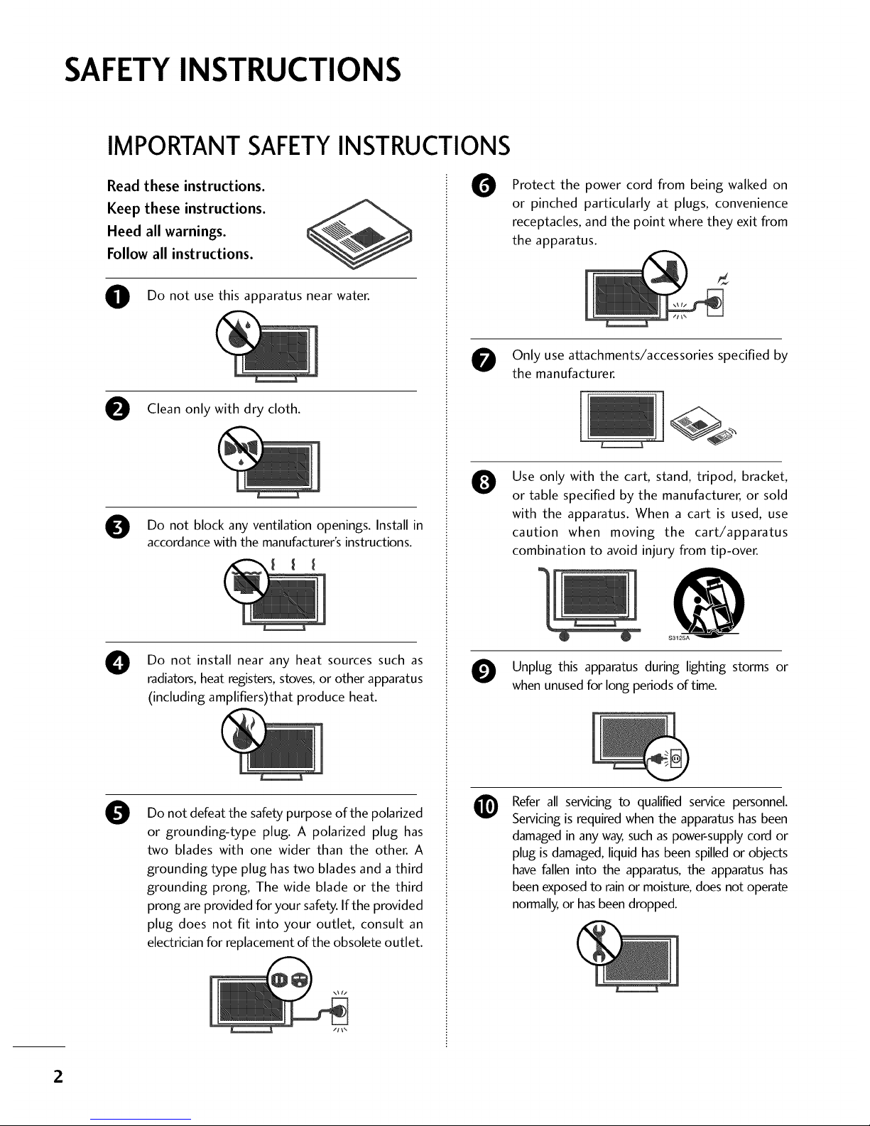
Read these instructions.
Keep these instructions.
Heed all warnings.
Follow all instructions.
O Do not usethis apparatus near water.
Clean only with dry cloth.
Do not block ventilation openings. Install in
any
accordance with the manufacturer's instructions.
0
Do not install near any heat sources such as
radiators, heat registers, stoves, or other apparatus
(including amplifiers)that produce heat.
0
Do not defeat the safety purpose of the polarized
or grounding-type plug. A polarized plug has
two blades with one wider than the other. A
grounding type plug has two blades and a third
grounding prong, The wide blade or the third
prong are provided for your safety. If the provided
plug does not fit into your outlet, consult an
electrician for replacement of the obsolete outlet.
0
Protect the power cord from being walked on
or pinched particularly at plugs, convenience
receptacles, and the point where they exit from
the apparatus.
Only use attachments/accessories specified by
the manufacturer.
0
Use only with the cart, stand, tripod, bracket,
or table specified by the manufacturer, or sold
with the apparatus. When a cart is used, use
caution when moving the cart/apparatus
combination to avoid injury from tip-over.
Unplug this apparatus during lighting storms or
when unused for long periods of time.
Refer all servicing to qualified service personnel.
Servicing is required when the apparatus has been
damaged in any way, such as power-supply cord or
plug is damaged, liquid has been spilled or objects
have fallen into the apparatus, the apparatus has
been exposed to rain or moisture, does not operate
normally, or has been dropped.
2
Page 4
O
®
®
O
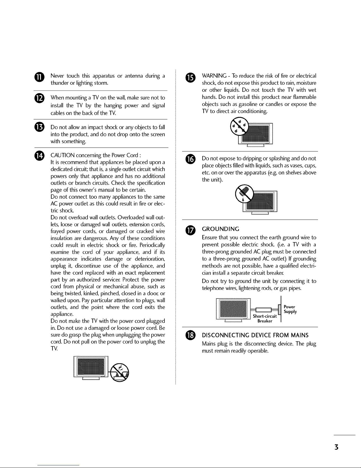
Never touch this apparatus or antenna during a
thunder or lighting storm.
When mounting a TV on the wall, make sure not to
install the TV by the hanging power and signal
cables on the back of the TV.
Do not allow an impact shock or any objects to fall
into the product, and do not drop onto the screen
with something.
CAUTION concerning the Power Cord :
It is recommend that appliances be placed upon a
dedicated circuit; that is,a single outlet circuit which
powers only that appliance and has no additional
outlets or branch circuits. Check the specification
page of this owner's manual to be certain.
Do not connect too many appliances to the same
AC power outlet asthis could result in fire or elec-
tric shock.
Do not overload wall outlets. Overloaded wall out-
lets, loose or damaged wall outlets, extension cords,
frayed power cords, or damaged or cracked wire
insulation are dangerous. Any of these conditions
could result in electric shock or fire. Periodically
examine the cord of your appliance, and if its
appearance indicates damage or deterioration,
unplug it, discontinue use of the appliance, and
have the cord replaced with an exact replacement
part by an authorized servicer. Protect the power
cord from physical or mechanical abuse, such as
being twisted, kinked, pinched, closed in adoor, or
walked upon. Payparticular attention to plugs, wall
outlets, and the point where the cord exits the
appliance.
Do not make the TV with the power cord plugged
in. Do not use a damaged or loose power cord. Be
sure do grasp the plug when unplugging the power
cord. Do not pull on the power cord to unplug the
TV.
O
@
O
O
WARNING - To reduce the risk of fire or electrical
shock, do not expose this product to rain, moisture
or other liquids. Do not touch the TV with wet
hands. Do not install this product near flammable
objects such as gasoline or candles or expose the
TV to direct air conditioning.
Do not exposeto dripping or splashinganddo not
placeobjects filled with liquids,suchasvases,cups,
etc.on or overthe apparatus(e.g.on shelvesabove
the unit).
GROUNDING
Ensure that you connect the earth ground wire to
prevent possible electric shock (i.e. a TV with a
three-prong grounded AC plug must be connected
to a three-prong grouned AC outlet) If grounding
methods are not possible, have a qualified electri-
cian install a separate circuit breaker.
Do not try to ground the unit by connecting it to
telephone wires, lightening rods, or gas pipes.
Short-circuit
Breaker
Power
Supply
DISCONNECTING DEVICE FROM MAINS
Mains plug is the disconnecting device. The plug
must remain readily operable.
3
Page 5

ANTENNAS
Outdoor antenna grounding
Ifan outdoor antenna is installed, follow the precau-
tions below. An outdoor antenna system should not
be located in the vicinity of overhead power linesor
other electric light or power circuits, or where it can
come in contact with such power lines or circuits as
death or serious injury can occur.
Besure the antenna system is grounded so asto pro-
vide some protection against voltage surges and
built-up static charges.
Section 810 of the National Electrical Code (NEC) in
the U.S.A.provides information with respect to prop-
er grounding of the mast and supporting structure,
grounding of the lead-in wire to an antenna dis-
chargeunit, sizeof grounding conductors, location of
antenna discharge unit, connection to grounding
electrodes and requirements for the grounding elec-
trode.
Antenna grounding according to the
National Electrical Code, ANSI/NFPA 70
Ground Clamp
NEC: National Electrical Code
Antenna Lead in Wire
Antenna Discharge Unit
(NEC Section 810-20)
Grounding Conductors
(NEC Section 810-21)
Ground Clamps
Power Service Grounding
Electrode System (NEC
Arf 250, Part H)
Cleaning
When cleaning, unplug the power cord and scrub
gently with a soft cloth to prevent scratching. Do not
spray water or other liquids directly on the TV as
electric shock may occur. Do not clean with chemi-
cals such as alcohol, thinners or benzene.
O Moving
Make sure the product is turned off, unplugged
and all cables have been removed. It may take 2 or
more people to carry larger TVs. Do not press
against or put stress on the front panel of the TV.
O
@
Ventilation
Install your TV where there isproper ventilation. Do
not install in a confined space such as a bookcase.
Do not cover the product with cloth or other mate-
rials (e.g.) plastic while plugged in. Do not install in
excessivelydusty places.
Ifyou smell smoke or other odors coming from the
TV or hear strange sounds, unplug the power cord
contact an authorized service center.
Do not strongly the panel with ahand or
press upon
sharp object such as nail, pencil or pen, or make a
scratch on it
l!_ Keep product away sunlight.
the from direct
For LCD TV
If the TV feels cold to the touch, there may be
a small "flicker" when it is turned on. This is
normal, there is nothing wrong with TV.
Some minute dot defects may be visible on the
screen, appearing as tiny red, green, or blue
spots. However, they have no adverse effect on
the monitor's performance.
Avoid touching the LCD screen or holding your
finger(s) against it for long periods of time.
Doing so may produce some temporary dis-
tortion effects on the screen.
ON DISPOSAL
(Only Hg lamp used LCD TV)
The fluorescent lamp used in this product contains
a small amount of mercury. Do not dispose of
this product with general household waste.
Disposal of this product must be carried out in
accordance to the regulations ofyour local authority.
4
Page 6
CONTENTS
WARNING / CAUTION ............................ 1
SAFETY INSTRUCTIONS .......................... 2
FEATURES OF THIS TV ............................. 7
PREPARATION
Accessories ...................................................... 8
Front Panel Information ..................................... 9
Back Panel Information .................................... 10
Stand Instruction ............................................. 12
Cable Management ......................................... 13
Desktop Pedestal Installation ............................ 14
Swivel Stand.................................................... 14
Attaching the TV to a desk ............................... 15
VESAWall Mounting ........................................ 16
Securing the TV to the wall to prevent falling
Whenthe TV is usedon a stand .......................... 17
Antenna or Cable Connection .......................... 18
MPI Card Slot / PPV Card Installation ............... 19
HD ReceiverSetup
- Component Connection ........................... 20
- HDMI Connection ..................................... 21
- DVI to HDMI Connection .......................... 22
DVD Setup
- Component Connection ............................ 23
- HDMI Connection .................................... 24
VCR Setup
- Antenna Connection ................................. 25
- Composite (RCA) Connection ................... 25
Other A/V Source Setup ................................. 26
PC Setup
- VGA (D-Sub 15 pin) Connection ............... 27
- DVI to HDMI Connection .......................... 28
- Screen Setup for PC mode ........................ 29
Audio Out Connection .................................... 33
WATCHING TV/CHANNEL CONTROL
Remote Control Functions ............................... 34
Turning On TV ................................................ 36
Channel Selection ........................................... 36
Volume Adjustment ......................................... 36
On-Screen Menus Selection ............................. 37
Channel Setup
- Auto Scan (Auto Tuning) ........................... 38
- Add / Delete Channel (Manual Tuning) ...... 39
- Channel Editing ........................................ 40
Channel Label ................................................. 41
Input List ........................................................ 42
Example Electronic ProgramGuide ................... 43
PIP (Picture-ln-Picture) .................................... 44
Picture Size (Aspect Ratio) Control .................. 46
Preset Picture Settings
- Picture Mode - Preset ............................... 49
- Color Tone - Preset .................................. 50
Manual Picture Adjustment
- Picture Mode - User Mode ........................ 51
Picture Improvement Technology ..................... 52
Advanced Control- Black (Darkness) Level....... 53
Advanced Control - EyeCare ........................... 54
Advanced Control- Film Mode ......................... 55
Picture Reset ................................................. 56
7...................
SOUND & LANGUAGE CONTROL
Auto Volume Leveler (Auto Volume) ................. 57
Preset Sound Settings (Sound Mode) .............. 58
Sound Setting Adjustment - User Mode ........... 59
- SRSTruSurround XT ................................. 60
Clear Voice ..................................................... 61
Balance .......................................................... 62
TV Speakers On/Off Setup .............................. 63
Audio Reset ................................................... 64
Stereo/SAP Broadcast Setup ........................... 65
Audio Language .............................................. 66
On-Screen Menus Language Selection .............. 67
Caption Mode
- Analog Broadcasting System Captions ....... 68
- Digital Broadcasting System Captions ........ 69
- Caption Option ....................................... 70
TIME SETTING
Clock Setting
- Auto Clock Setup .................................... 71
- Manual Clock Setup ................................. 72
Auto On/Off Time Setting .............................. 73
Sleep Timer Setting ......................................... 74
Auto Shut-off Setting ....................................... 75
S
Page 7
PARENTALCONTROL/RATINGS
Set Password & Lock System ........................... 76
Channel Blocking ............................................ 79
Movie & TV Rating ......................................... 80
Downloadable Rating ...................................... 83
External Input Blocking .................................... 84
Interactive TV Setup ........................................ 85
Installer Overview ............................................ 86
Interactive TV Overview ................................... 87
Commercial Mode Setup for Master TV ............ 88
Master TV Profile Setup Learning/Teaching with
USB Memory Card .......................................... 89
TLL-1100A Cloning Connections/Learning Setup
...................................................................... 1
LT2002 Cloning Connections/Learning Setup .. 92
LT2002 Cloning Learning Setup ...................... 93
Cloning Connections/Teaching Setup .............. 94
Installer Menu ................................................. 95
Reference: Detailed Instructions For Making A
Master TV ..................................................... 101
Reference: Procedures for adding Channel Label
Icons/Custom Channel Labels (2-5-4 + MENU
Mode) .......................................................... 102
Reference: Clonable Menu Features ................ 103
Reference: Power Saving Setup ....................... 104
TV Aux Input Configuration ........................... 106
TV Camport Auto Sense Operation ................ 107
z
APPENDIX
Troubleshooting ............................................ 108
Reference: LT2002 Cloning Procedure
Troubleshooting ............................................. 110
Troubleshooting FlowChart ............................ 111
Commercial Mode Check ................................ 112
Reference: RJPmodel list and input hierarchy... 112
Glossary of Terms .......................................... 113
Maintenance .................................................. 114
Product Specifications .................................... 114
Programming the Remote Control ................... 115
IR Codes ....................................................... 118
Open Source License ..................................... 120
6
Page 8
FEATURES OF THIS TV
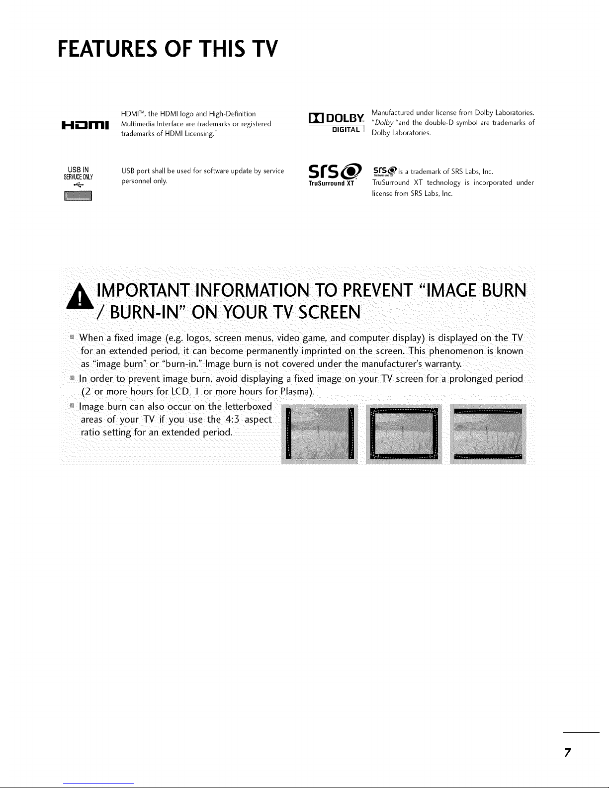
HDMP, the HDMI logo and High-Definition
Hm_ll[11111 Multimedia Interface are trademarks or registered
trademarks of HDMI Licensing."
Manufactured under license from Dolby Laboratories.
DOLBY "Dolbz"and the double-D symbol are trademarks of
DIGITAL J Dolby Laboratories.
USBIN USB port shall be used for software update by service srs
SERVUCEONLY
personnel only. TruSurround XT
SsrS_ is a trademark of SRS Labs, Inc.
TruSurround XT technology is incorporated under
license from SRS Labs, Inc.
,I_ IMPORTANT INFORMATION TO PREVENT"IMAGE BURN
/ BURN-IN" ON YOURTV SCREEN
When a fixed image (e.g. Iogos. screen menus, video game. and computer display) is displayed on the TV
for an extended period, it can become permanently imprinted on the screen. This phenomenon is known
as "image burn" or "burn-in." Image burn is not covered under the manufacturer's warranty.
In order to prevent image burn. avoid displaying a fixed image on your TV screen for a prolonged period
(2 or more hours for LCD. 1 or more hours for Plasma).
Image burn can also occur on the letterboxed
areas of your TV if you use the 4:3 aspect
ratio setting for an extended period.
7
Page 9
PREPERATION
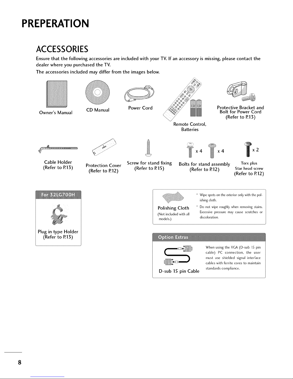
ACCESSORIES
Ensure that the following accessories are included with your TV. If an accessory is missing, please contact the
dealer where you purchased the TV.
The accessories included may differ from the images below.
Owner's Manual
CD Manual
Power Cord
Remote Control,
Batteries
Protective Bracket and
Bolt for Power Cord
(Refer to R13)
x4 x4
Cable Holder
(Refer to P.13) Protection Cover Screw for stand fixing Bolts for stand assembly Torx plus
(Refer to R12) (Refer to R15) (Refer to R12) Star head screw
(Refer to R12)
Plug in type Holder
(Refer to R13)
Polishing Cloth
(Not included with all
models,)
* Wipe spots on the exterior only with the pol-
ishing cloth.
* Do not wipe roughly when removing stains.
Excessive pressure may cause scratches or
discoloration.
D-sub 15 pin Cable
When using the VGA (D-sub 15 pin
cable) PC connection, the user
must use shielded signal interface
cables with ferrite cores to maintain
standards compliance,
8
Page 10
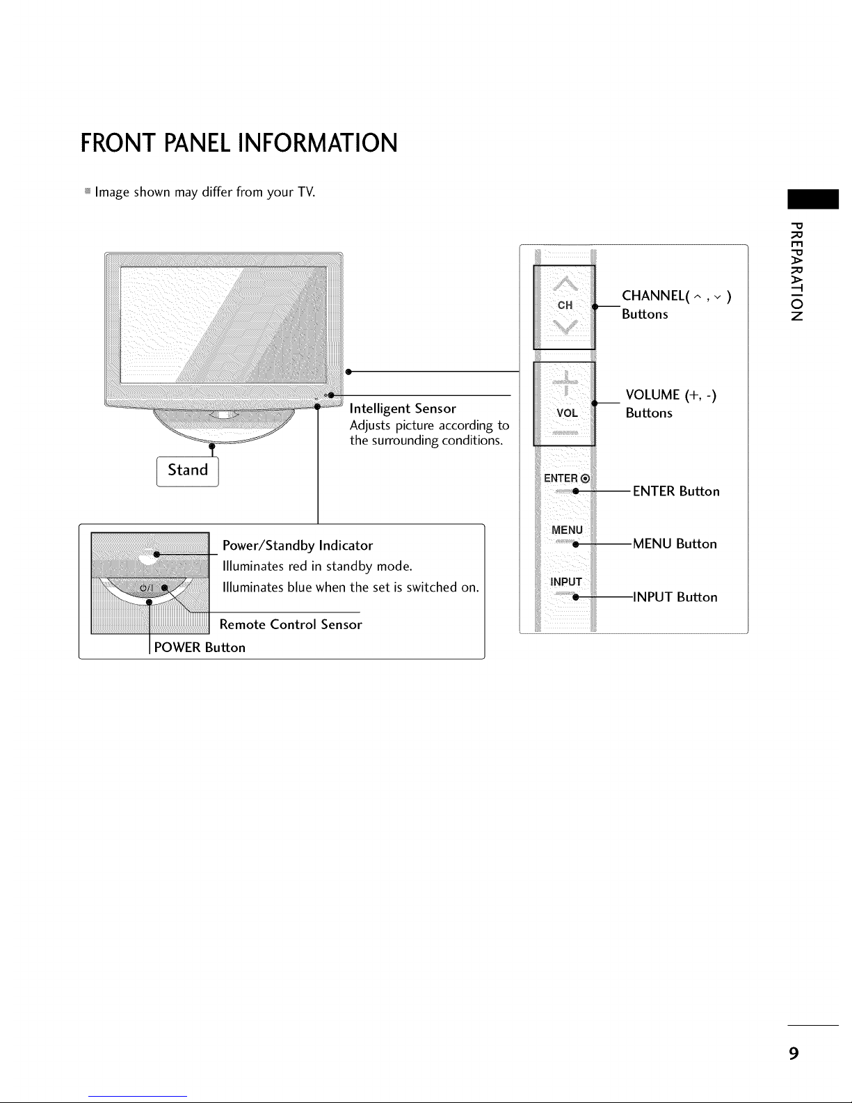
FRONTPANELINFORMATION
_ Image shown may differ from your TV.
Stand
@
Intelligent Sensor
Adjusts picture according to
the surrounding conditions.
Power/Standby Indicator
Illuminates red in standby mode.
Illuminates blue when the set is switched on.
Remote Control Sensor
POWER Button
_iiU¸¸¸ !_!
CH :,--
!;ii i[il
iiiii
VOL iii
E.TER®IIIii
uE.uiiii
CHANNEL(^ ,v )
Buttons
VOLUME (+,-)
Buttons
ENTER Button
MENU Button
INPUT Button
"O
_o
m
_o
0
z
9
Page 11
PREPARATION
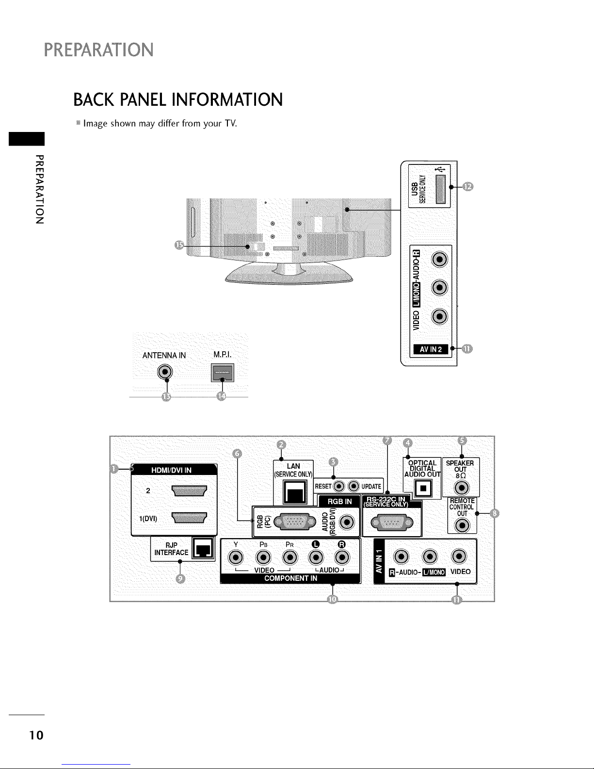
BACK PANELINFORMATION
_ Image shown may differ from your TV.
_a
r.l-I
_a
0
Z
iiiiiiiiiiiiiii; lii]}iiiiiiiiiii:itii_i_i_i!_i!_i!_i!_i!_i!_i!_i!_i!_i!_i!/i!_i!_i!_I
iiiii¸: _ii_i_ii!!iiiiilililii/iiiilil
iiiiiiiiiiiiiiiiiiiiiiiiiiiiiil:_;!;!;!;!;!;!;!;!!!_ii!;;;;;;;ii_i iiFiiiiiiiiJi¸iilii]iiii!iiiiiiiiiiiiiiiiiii!!!i]iiiiiii!!i!iiiilii!iiiiiiiiiiiiiiiii!iiiii¸
/
[]
I
10
Page 12
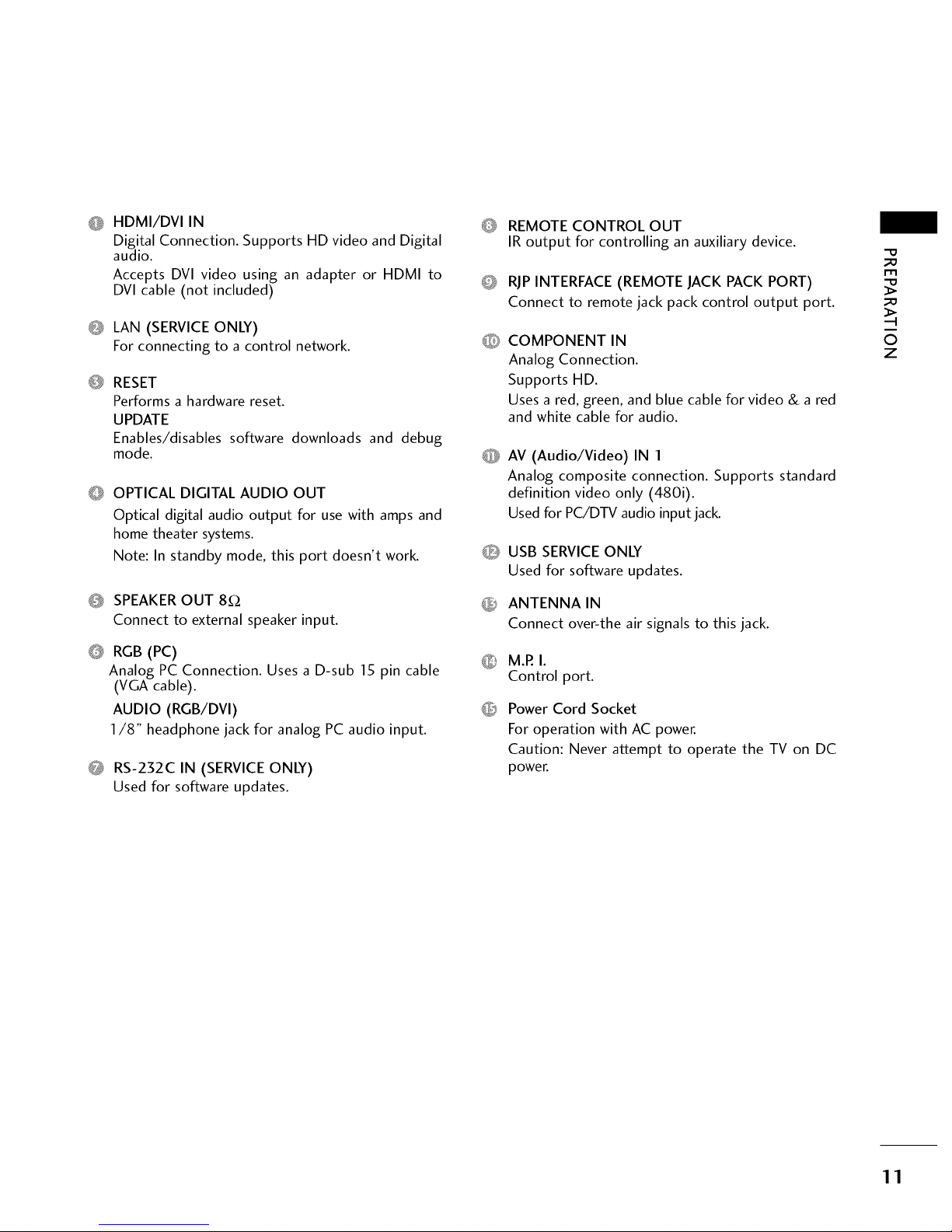
O HDMI/DVI IN
Digital Connection. Supports HD video and Digital
audio.
Accepts DVI video using an adapter or HDMI to
DVI cable (not included)
Q LAN (SERVICE ONLY)
For connecting to a control network.
@
RESET
Performs a hardware reset.
UPDATE
Enables/disables software downloads and debug
mode.
O OPTICAL DIGITAL AUDIO OUT
Optical digital audio output for use with amps and
home theater systems.
Note: In standby mode, this port doesn't work.
0 SPEAKEROUT 8£2
Connect to external speaker input.
@
RGB (PC)
Analog PC Connection. Uses a D-sub 15 pin cable
(VGA cable).
AUDIO (RGB/DVI)
1/8" headphone jack for analog PC audio input.
0 RS-232C IN (SERVICEONLY)
Used for software updates.
O
REMOTE CONTROL OUT
IR output for controlling an auxiliary device.
RJPINTERFACE (REMOTE JACK PACK PORT)
Connect to remote jack pack control output port.
COMPONENT IN
Analog Connection.
Supports HD.
Uses a red, green, and blue cable for video & a red
and white cable for audio.
AV (Audio/Video) IN 1
Analog composite connection. Supports standard
definition video only (480i).
Used for PC/DTV audio input jack.
O USB SERVICE ONLY
Used for software updates.
_ ANTENNA IN
Connect over-the air signals to this jack.
M.P.I.
Control port.
Power Cord Socket
For operation with AC power.
Caution: Never attempt to operate the TV on DC
power.
_D
_D
©
z
11
Page 13
?RZRARATION
m
0
z
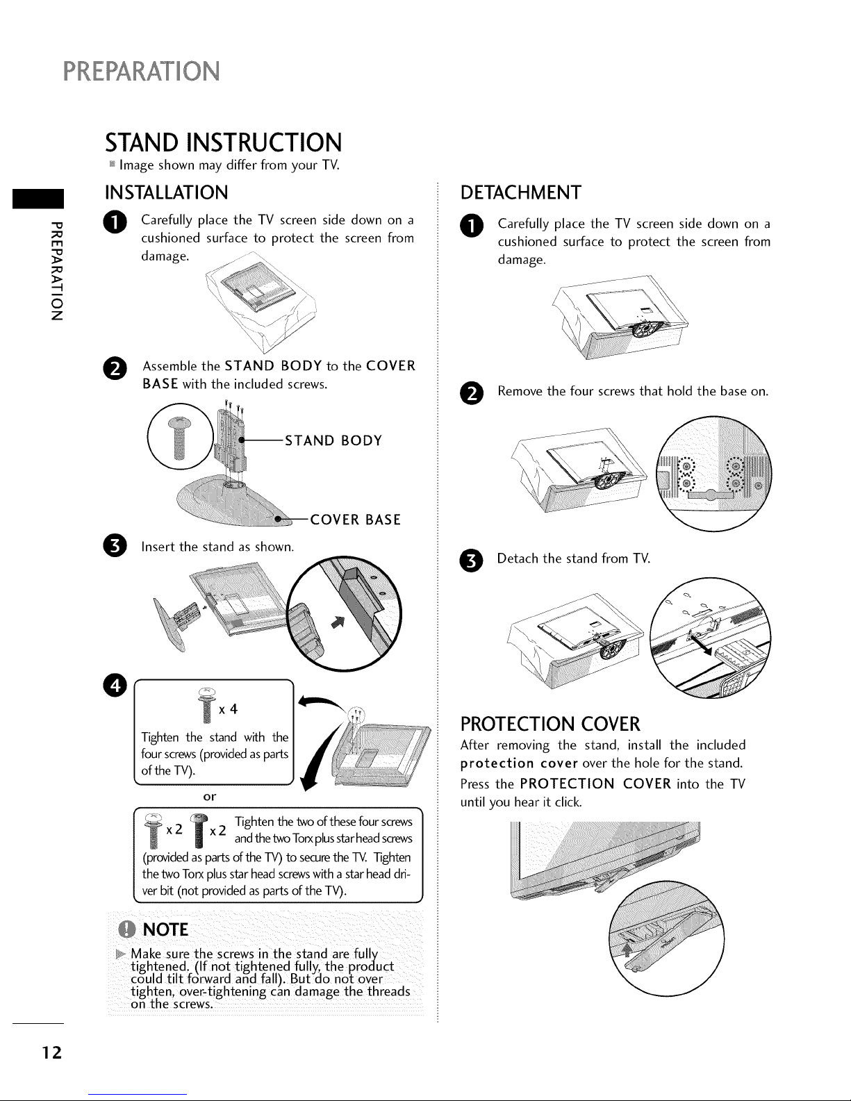
STAND INSTRUCTION
_ Image shown may differ from your TV.
INSTALLATION
O
Carefully place the TV screen side down on a
cushioned surface to protect the screen from
damage.
O ssemble the STAND BODY to the COVER
BASE with the included screws.
BODY
O Insert the stand as shown.
ER BASE
O
4
Tighten the stand with the
four screws(provided asparts
of the TV).
or
Tighten the two of these four screws
2 bx2 andthe tv_ Torxplusstarheadscrews
(providedasparts of the TV) to securethe TV. Tighten
the two Torx plusstar headscrewswith a star headdri-
ver bit (not provided as parts of the TV).
1
ieN EZ! :b i¸¸%¸¸¸¸¸?¸¸¸¸!¸¸¸¸¸¸¸¸¸¸¸¸¸¸¸¸¸¸
}_, Make Sure the Screws nthe stand are fully i
tigh.tened. (If not tightened fully_ the product i
could tilt f6rward and fall). But do not over
tighten over-t ghtening can damage the threads
on the screws.
DETACHMENT
O
0
Carefully place the TV screen side down on a
cushioned surface to protect the screen from
damage.
,_ii!!i!iiiiiiiiiiiiiiiii_ii!_¸¸¸_
Remove the four screws that hold the base on.
0
Detach the stand from TV.
PROTECTION COVER
After removing the stand, install the included
protection cover over the hole for the stand.
Press the PROTECTION COVER into the TV
until you hear it click.
12
Page 14
CABLEMANAGEMENT
_ Image shown may differ from your TV.
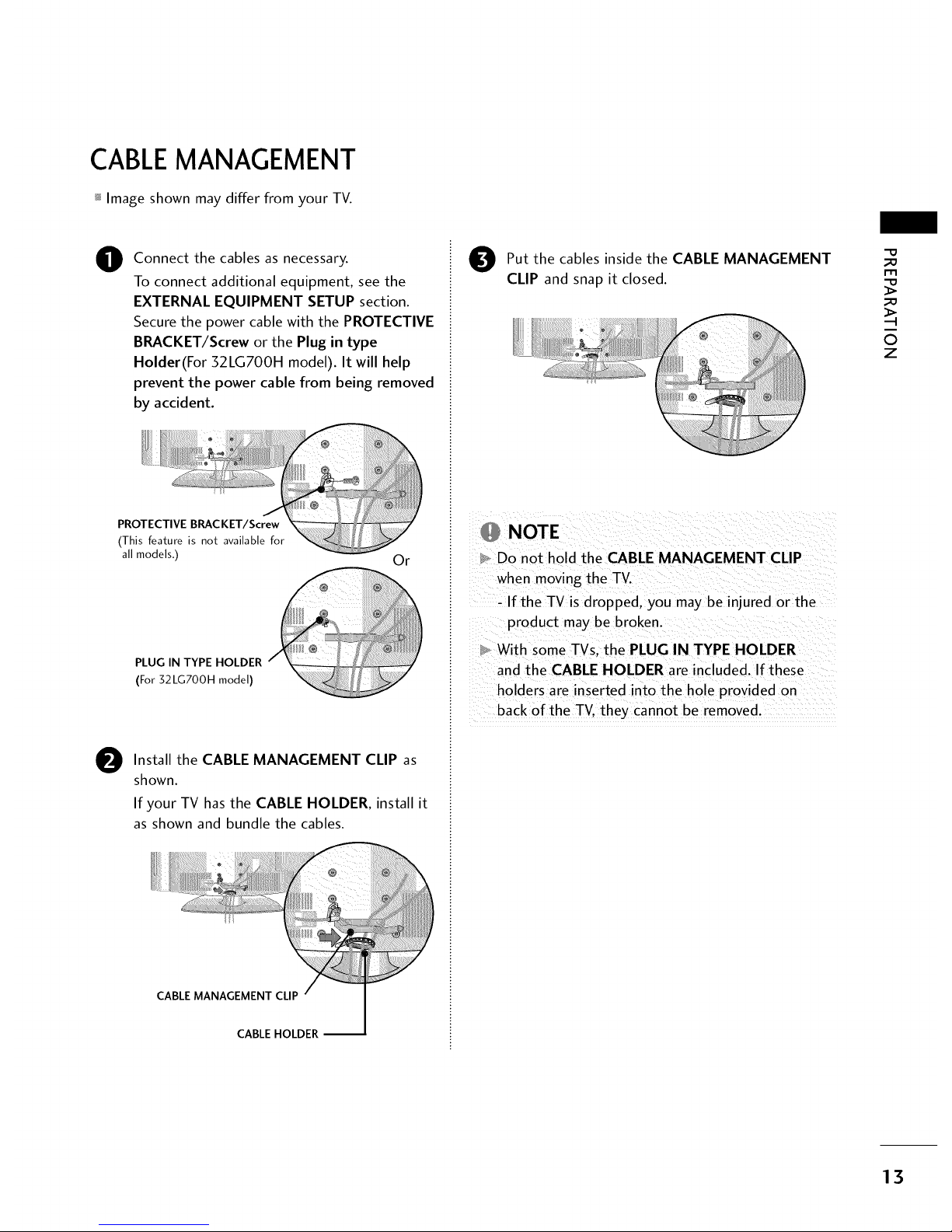
O
Connect the cables as necessary.
To connect additional equipment, see the
EXTERNAL EQUIPMENT SETUP section.
Secure the power cable with the PROTECTIVE
BRACKET/Screw or the Plug in type
Holder(For 32LG700H model). It will help
prevent the power cable from being removed
by accident.
PROTECTIVE BRACKET/Screw
(This feature is not available for
all models.)
Or
PLUG IN TYPE HOLDER
(For32LGT00Hmodel)
O
Install the CABLE MANAGEMENT CLIP as
shown.
If your TV hasthe CABLE HOLDER, install it
as shown and bundle the cables.
CABLE MANAGEMENT CLIP
CABLE HOLDER
O ut the cables inside the CABLE MANAGEMENT
CLIP and snap it closed.
NOTE
Do not hold the CABLE MANAGEMENT CLIP
when moving the TV.
- If the TV is dropped, you may be injured or the
product may be broken.
With some TVs. the PLUG IN TYPE HOLDER
and the CABLE HOLDER are included. If these
holders are inserted into the hole provided on
back of the TV. they cannot be removed.
_D
m
_D
©
z
13
Page 15
?RERARAI°ION
_o
rT1
_o
©
z
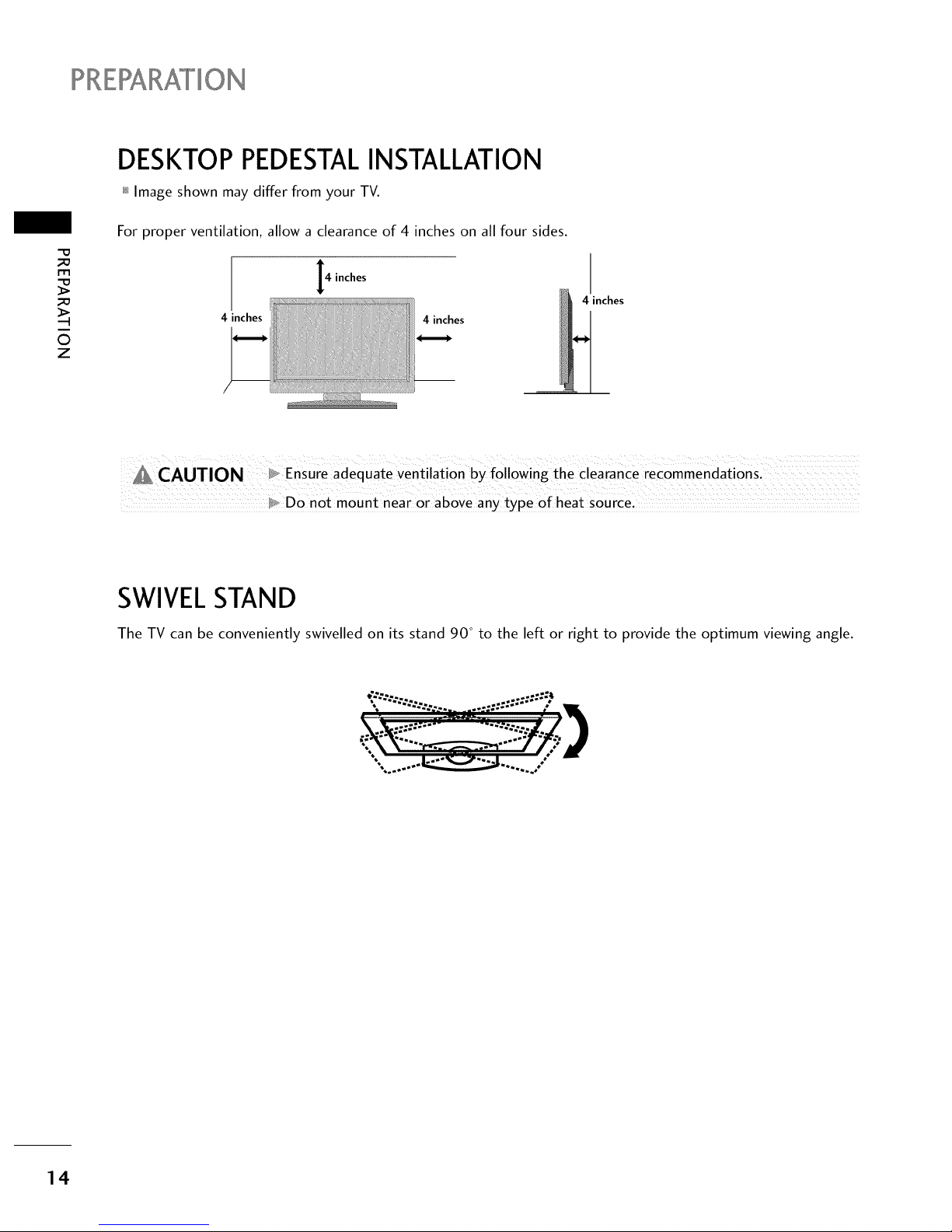
DESKTOP PEDESTALINSTALLATION
_ Image shown may differ from your TV.
For proper ventilation, allow a clearance of 4 inches on all four sides.
4 inches
4 inches
4 inches
4 inches
_, Do not mount near or above any type of heat source.
SWIVELSTAND
The TV can be conveniently swivelled on its stand 90 ° to the left or right to provide the optimum viewing angle.
14
Page 16
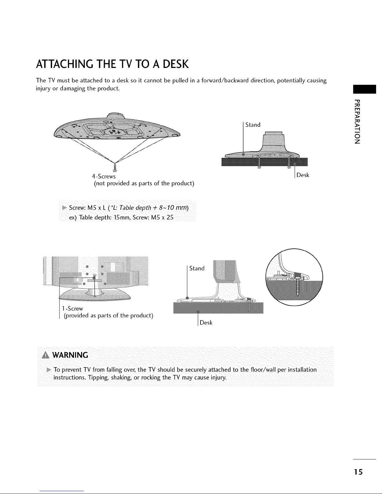
ATTACHING THE TV TO A DESK
The TV must be attached to a desk so it cannot be pulled in a forward/backward direction, potentially causing
injury or damaging the product.
-% / ./
% .._-J
'%._ ./f
4-Screws
(not provided as parts of the product)
Stand
Desk
_D
_D
O
z
_o screw: MSXL ( *L_ Tabie depth _ 8C lo mm)
ex) Table dePth: !5 ram, Screw: M5 X 25
1-Screw
(provided as parts of the product)
Stand
Desk
_ To prevent TV from fal ing over, the TV should be securely attached to the floor/wall per installation
instructions: Tipping i shakingl 0r rocking the TV may cause injury.
15
Page 17
PRERARAI°ION
VESAWALL MOUNTING
-O
_a
i-rl
_a
0
z
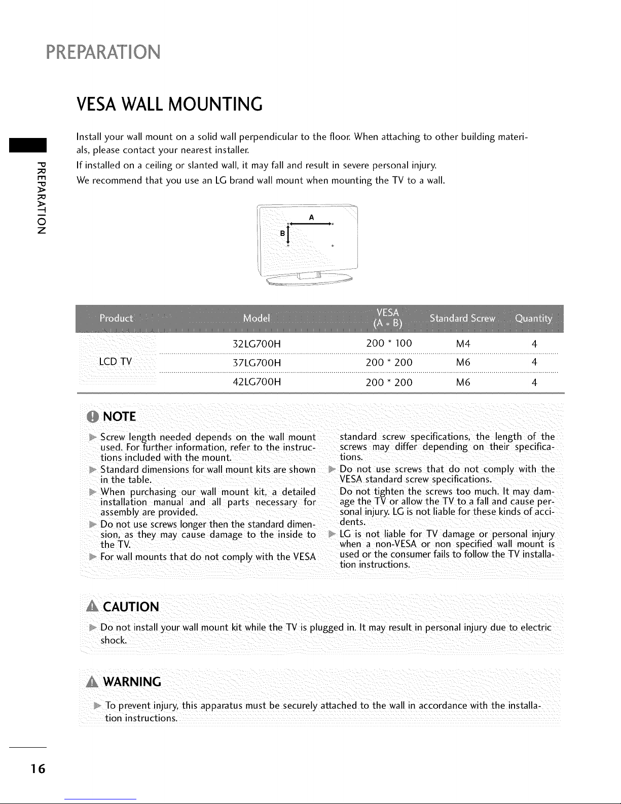
Install your wall mount on a solid wall perpendicular to the floor. When attaching to other building materi-
als, please contact your nearest installer.
If installed on a ceiling or slanted wall, it may fall and result in severe personal injury.
We recommend that you use an LG brand wall mount when mounting the TV to a wall.
J
32LG700H 200 * 100 M4 4
.....................................................................................................................................................................................................
LCDTV 37LG700H 200 * 200 M6 4
.....................................................................................................................................................................................................
42LG700H 200 * 200 M6 4
NOTE
Screw length needed depends on the wall mount standard screw specifications, the length of the
used. For further information, refer to the instruc- screws may differ depending on their specifica-
tions included with the mount, tions.
Standard dimensions for wall mount kits are shown Do not use screws that do not comply with the
in the table. VESA standard screw specifications.
When purchasing our wall mount kit. a detailed Do not tighten the screws too much. It may dam-
installation manual and all parts necessary for age the TV or allow the TV to a fall and cause per-
assembly are provided, sonal injury. LG is not liable for these kinds of acci-
Do not use screws longer then the standard dimen- dents.
sion. as they may cause damage to the inside to LG is not liable for TV damage or personal injury
the TV. when a non-VESA or non specified wall mount is
For wall mounts that do not comply with the VESA used or the consumer fails to follow the TV installa-
tion instructions.
Do not install your wall mount kit while the TV is plugged in. It may result in personal injury due to electric
shock.
WARNING
To prevent injury, this apparatus must be securelv attached to the wall in accordance with the installa-
tion instructions.
16
Page 18
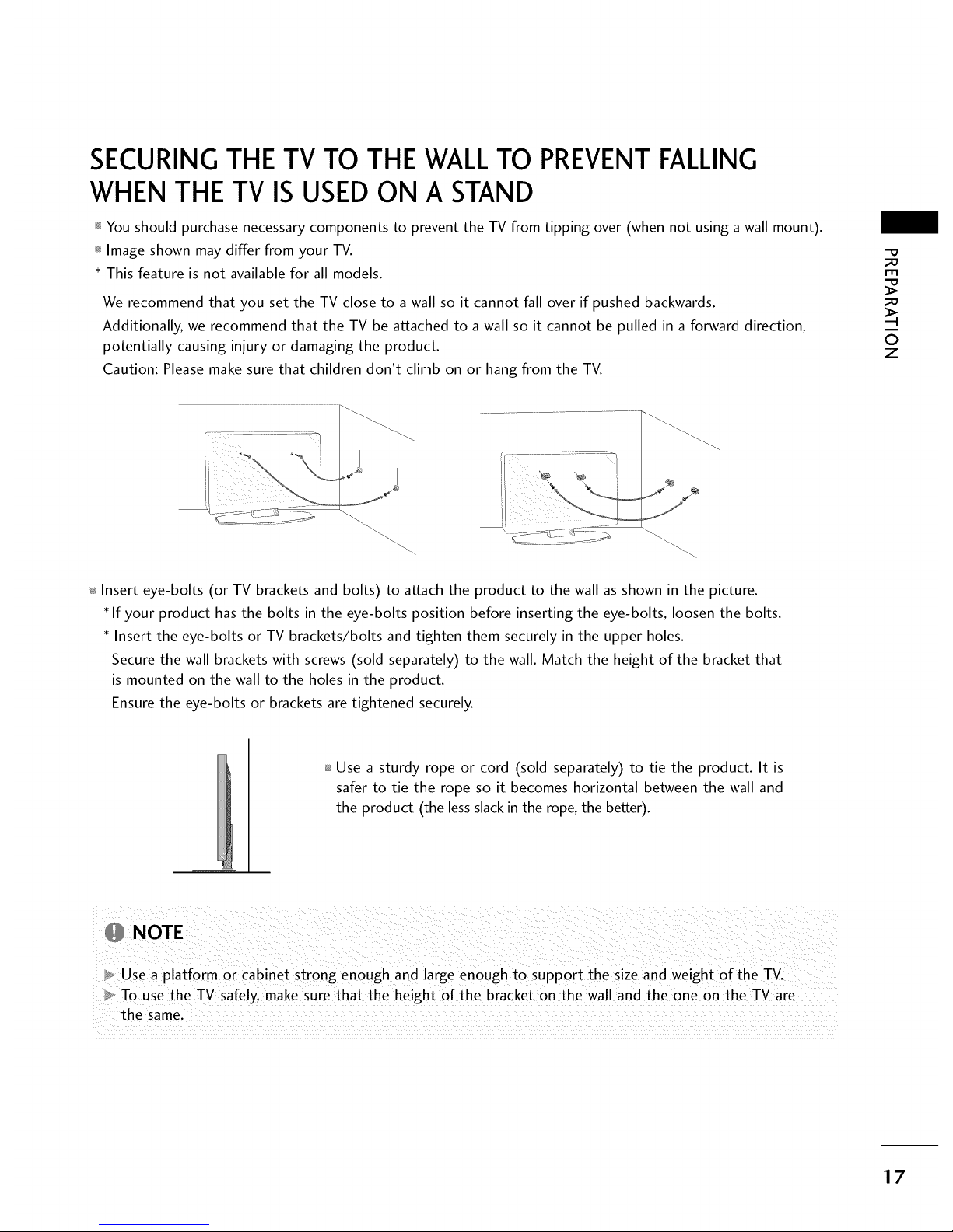
SECURINGTHE TV TO THE WALLTO PREVENTFALLING
WHEN THE TV IS USEDON A STAND
_ You should purchase necessary components to prevent the TV from tipping over (when not using a wall mount).
_ Image shown may differ from your TV.
* This feature is not available for all models.
We recommend that you set the TV close to a wall so it cannot fall over if pushed backwards.
Additionally, we recommend that the TV be attached to a wall so it cannot be pulled in a forward direction,
potentially causing injury or damaging the product.
Caution: Please make sure that children don't climb on or hang from the TV.
_D
m
_D
©
z
_ Insert eye-bolts (or TV brackets and bolts) to attach the product to the wall as shown in the picture.
If your product has the bolts in the eye-bolts position before inserting the eye-bolts, loosen the bolts.
Insert the eye-bolts or TV brackets/bolts and tighten them securely in the upper holes.
Secure the wall brackets with screws (sold separately) to the wall. Match the height of the bracket that
is mounted on the wall to the holes in the product.
Ensure the eye-bolts or brackets are tightened securely.
Use a sturdy rope or cord (sold separately) to tie the product. It is
safer to tie the rope so it becomes horizontal between the wall and
the product (the less slack in the rope, the better).
NOTE
Use a platform or cabinet strong enough and large enough to support the size and weight of the TV.
To use the TV safely, make sure that the height of the bracket on the wall and the one on the TV are
the same.
17
Page 19
?RERARATION
_ To prevent damage do not connect to the power outlet until all connections are made between the devices.
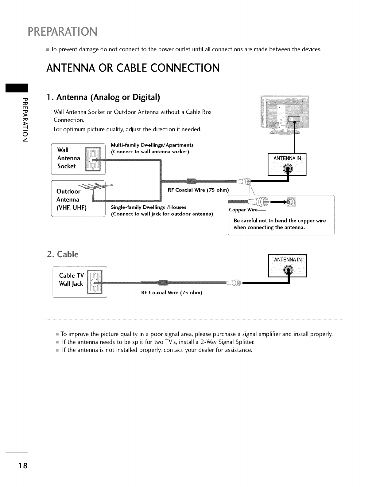
ANTENNA OR CABLECONNECTION
l-rl
©
z
1. Antenna (Analog or Digital)
Wall Antenna Socket or Outdoor Antenna without a Cable Box
Connection.
For optimum picture quality, adjust the direction if needed.
, _ Multi-family Dwellings/Apartments
Wall enna socket)
Antenna ANTENNA IN
Socket
Outdo RFCoaxial Wire (75 ohm) .................................................................
Antenna
(VHF, UHF) I Single-family Dwellings/Houses !Copper Wire_
) (Connect to wall jack for outdoor antenna)
I Be careful not to bend the copper wire
I when connecting the antenna.
2. CaNe
Cable TV
Wall Jack
...........................................................................%
..........._i.
I
To improve the picture quality in a poor signal area, please purchase a signal amplifier and install properly.
If the antenna needs to be split for two TV's, install a 2-Way Signal Splitter.
If the antenna is not installed properly, contact your dealer for assistance.
18
Page 20
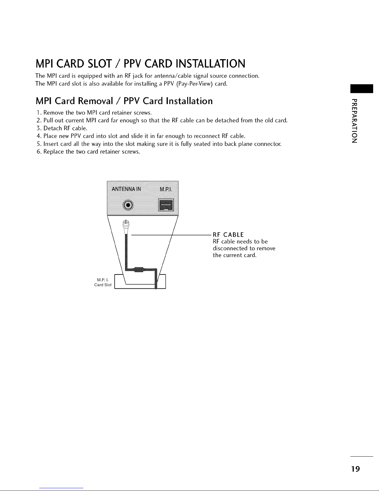
MPI CARD SLOT/ PPVCARD INSTALLATION
The MPI card is equipped with an RFjack for antenna/cable signal source connection.
The MPI card slot is also available for installing a PPV (Pay-Per-View) card.
MPI Card Removal/PPV Card Installation
1. Remove the two MPI card retainer screws.
2. Pull out current MPI card far enough so that the RF cable can be detached from the old card.
3. Detach RF cable.
4. Place new PPV card into slot and slide it in far enough to reconnect RF cable.
5. Insert card all the way into the slot making sure it is fully seated into back plane connector.
6. Replace the two card retainer screws.
-0
_o
m
_o
©
z
RF CABLE
RF cable needs to be
disconnected to remove
the current card.
M.P.I.
Card Slot
19
Page 21
EXTERNAL EQUIPMENT SETUP
To prevent the equipment damage, never plug in any power cords until you have finished connecting all equipment.
Image shown may differ from your TV.
HD RECEIVERSETUP
m
O
z
This TV can receive Digital Over-the-air or Digital Cable signals without an external digital set-top box. However,
if you do receive digital signals from a digital set-top box or other digital external device, refer to the figure as
shown below.
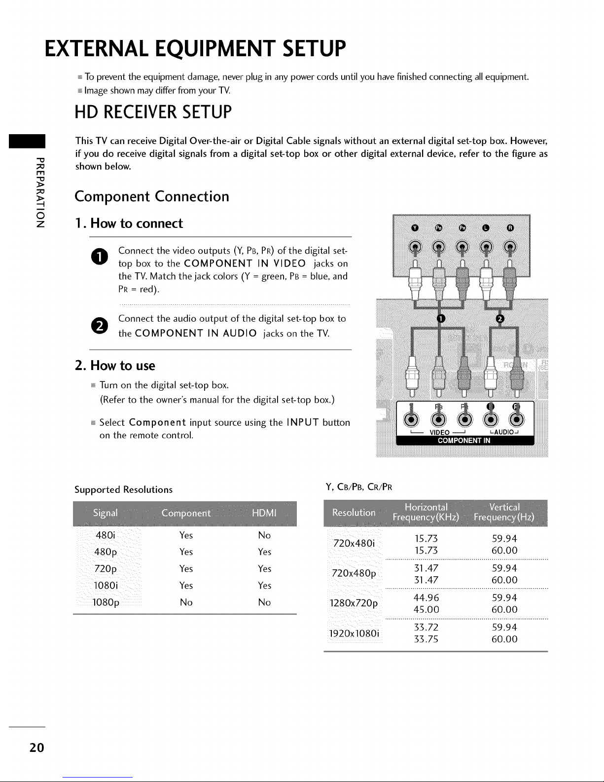
Component Connection
1. How to connect
0
Connect the video outputs (Y, PB, PR) of the digital set-
top box to the COMPONENT IN VIDEO jacks on
the TV. Match the jack colors (Y = green, PB = blue, and
PR = red).
O onnect the audio output of the digital set-top box to
the COMPONENT IN AUDIO jacks on theTV.
2. How to use
Turn on the digital set-top box.
(Refer to the owner's manual for the digital set-top box.)
Select Component input source using the INPUT button
on the remote control.
Supported Resolutions
Y, CB/PB, CR/PR
480i
480p
1080i
1080p
Yes
Yes
Yes
Yes
No
No 15.75 59.94
720x480i
Yes 15.75 60.00
Yes 51.47 59.94
720x480p 51.47 60.00
Yes ...................................................................................
44.96 59.94
No 1280x720p
45.00 60.00
55.72 59.94
1920x1080i 33.75 60.00
20
Page 22
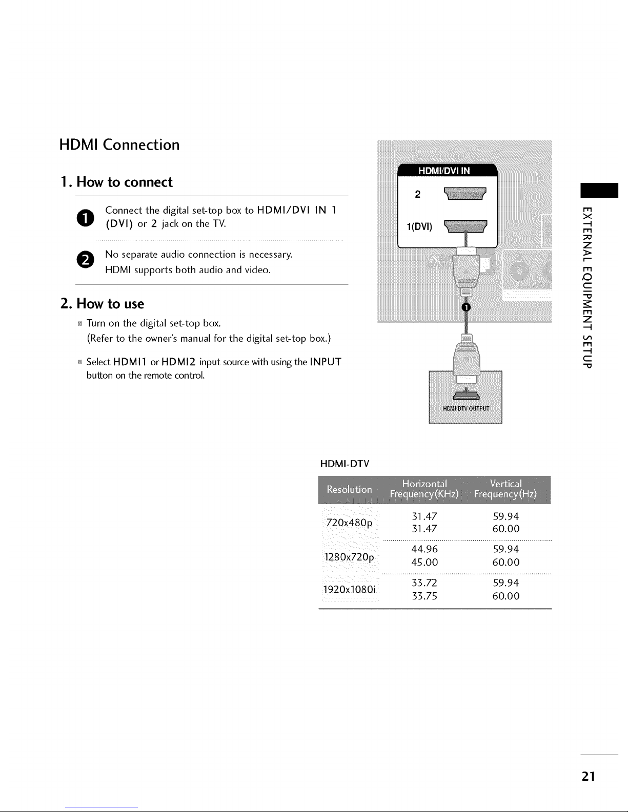
HDMI Connection
1. How to connect
O onnect the digital set-top box to HDMI/DVI IN 1
(DVI) or 2 jack on the TV.
O No separate audio connection is necessary.
HDMI supports both audio and video.
2. How to use
Turn on the digital set-top box.
(Refer to the owner's manual for the digital set-top box.)
Select HDMI 1 or HDMI2 input source with using the INPUT
button on the remote control.
m
x
m
_D
z
m
X:)
c
m
z
m
c
HDMI-DTV
31.47 59.94
720x480p
31.47 60.00
..............:_:_19_...........................s9i_:_................
!280X720p 45.00 60.00
...................................................................................
33.72 59.94
1920xl 080i 33.75 60.00
21
Page 23
EXTERNALEQUIPMENT SETUP
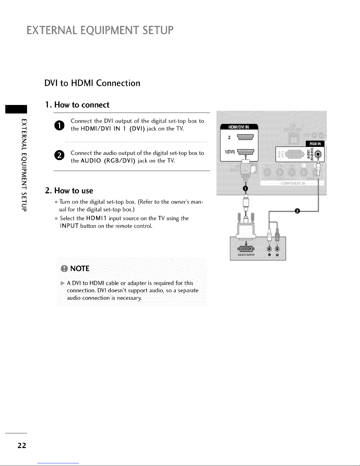
DVI to HDMI Connection
1. How to connect
m
x
m
z
m
X:)
c
m
z
m
c
O onnect the DVI output of the digital set-top box to
theHDMI/DVl IN 1 (DVl) jack on the TV.
O Connect the audio output of the digital set-top box to
the AUDIO (RGB/DVI) jack on the TV.
2. How to use
Turn on the digital set-top box. (Refer to the owner's man-
ual for the digital set-top box.)
Select the HDMI 1 input source on the TV using the
INPUT button on the remote control.
,_ NOTE
A DVI to HDMI cable or adapter is required for this
connection. DVl doesn't support audio, so a separate
audio connection is necessary.
22
Page 24
DVDSETUP
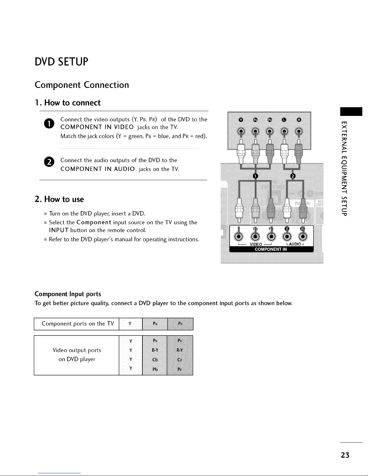
Component Connection
1. How to connect
O
Connect the video outputs (Y, PB, PR) of the DVD to the
COMPONENT IN VIDEO jacks on the TV.
Match the jack colors (Y = green, PB = blue, and PR = red).
O Connect the audio outputs of the DVD to the
COMPONENT IN AUDIO jacks on theTV.
2. How to use
_ Turn on the DVD player, insert a DVD.
_ Select the Component input source on the TV using the
INPUT button on the remote control.
_ Refer to the DVD player's manual for operating instructions.
i_i_i_i_i_i_i_i_i_i_i_i_i_i_i_i_i_i_i_i_i_i_i_i_i_i_i_i_i_i_i_i_i_i_i_i_i_i_i_i_i_i_i_i_i_i_i_i_i_i_i_i_i_i_i_i_i_i_i_i_i_i_i_i_i_i_i_i_i_i_i_i_i_i_i_i_i_i_i_i_i_i_i_i_i_i_i_i_i_i_i_i_i_i_i_i_i_i_i_i_i_i_i_i_i_i_i_i_i_i_i_i_i_i_i_i_i_i_i_i_i_i_i_i_i_i_i_i_i_i_i_i_i_i_i_i_i_i_i_i_i_i_i_i_i_i_i_i_i_i_i_i_i_i_i_i_i_i_i_i_i_i_i_i_i_i_i_i_i_i_i_i_i_i_i_i_i_i_i_i_i_i_i_i_i_i_i_i_i_i_i_i_i_i_i_i_i_i_i_i_i_i_i_i_i_i_i_i_i_i_i_i_i_i_i_i_i_i_i_i_i_i_i_i_i_i_i_i_i_i_i_i_i_i_i_i_!_!
m
X
_o
Z
x:)
C
Z
C
"O
Component Input ports
To get better picture quality, connect a DVD player to the component input ports as shown below.
Component ports on the TV
Video output ports
on DVD player
23
Page 25
EXTERNALEQUIPMENT SETUP
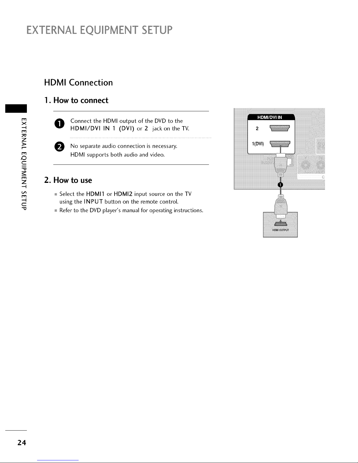
HDMI Connection
1. How to connect
m
x
m
_o
z
m
X:)
c
"0
m
z
m
c
"0
O Connect the HDMI output of the DVD to the
HDMI/DVI IN 1 (DVI) or2 jack on theTV.
O No audio connection is
separate necessary.
HDMI supports both audio and video.
2. How to use
Select the HDMI1 or HDMI2 input source on the TV
using the INPUT button on the remote control.
Refer to the DVD player's manual for operating instructions.
24
Page 26
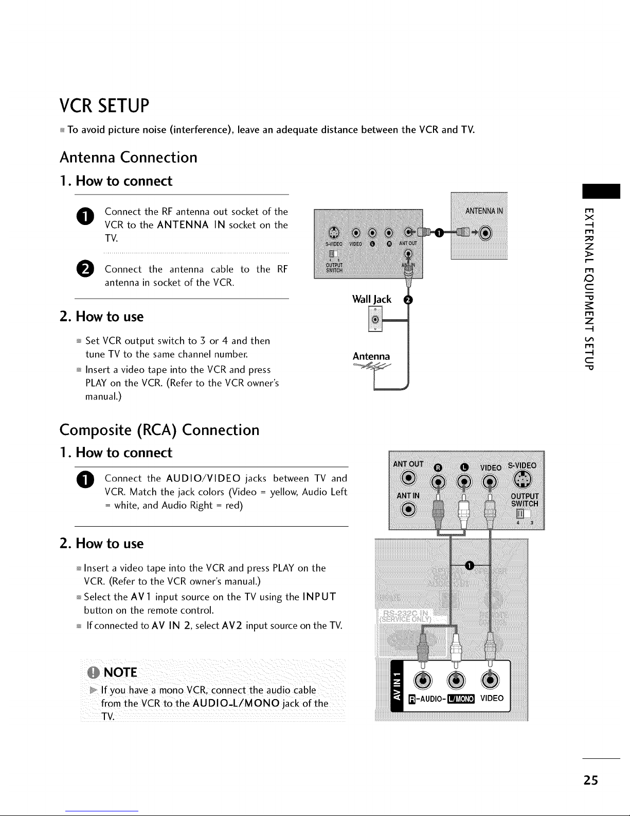
VCRSETUP
_ To avoid picture noise (interference), leave an adequate distance between the VCR and TV.
Antenna Connection
1. How to connect
O Connect the RF antenna out socket of the
VCR to the ANTENNA IN socket on the
TV.
Connect the antenna cable to the RF
antenna in socket of the VCR.
2. How to use
_ Set VCR output switch to 3 or 4 and then
tune TV to the same channel number.
_ Insert a video tape into the VCR and press
PLAY on the VCR. (Refer to the VCR owner's
manual.)
Wall Jack
Antenna
r_l
x
r_l
_o
z
r_l
X:)
c
"O
r_l
z
r_l
c
"O
Composite (RCA) Connection
1. How to connect
O
Connect the AUDIO/VIDEO jacks between TV and
VCR. Match the jack colors (Video = yellow, Audio Left
= white, and Audio Right = red)
2. How to use
_ Insert a video tape into the VCR and press PLAY on the
VCR. (Refer to the VCR owner's manual.)
_ Select the AV 1 input source on the TV using the INPUT
button on the remote control.
_ If connected to AV IN 2, select AM2 input source on the TV.
D_ If you have a mono VCR, connect the audio Cable
from the VCRto the AUDIO,L/MONO jack of the
TV.
25
Page 27
EXTERNALEQUIPMENT SETUP
I'1"1
><
,,-I
I"1"1
z
I"1"1
,0
c
I"1"1
z
,,-I
I"1"1
,-I
c
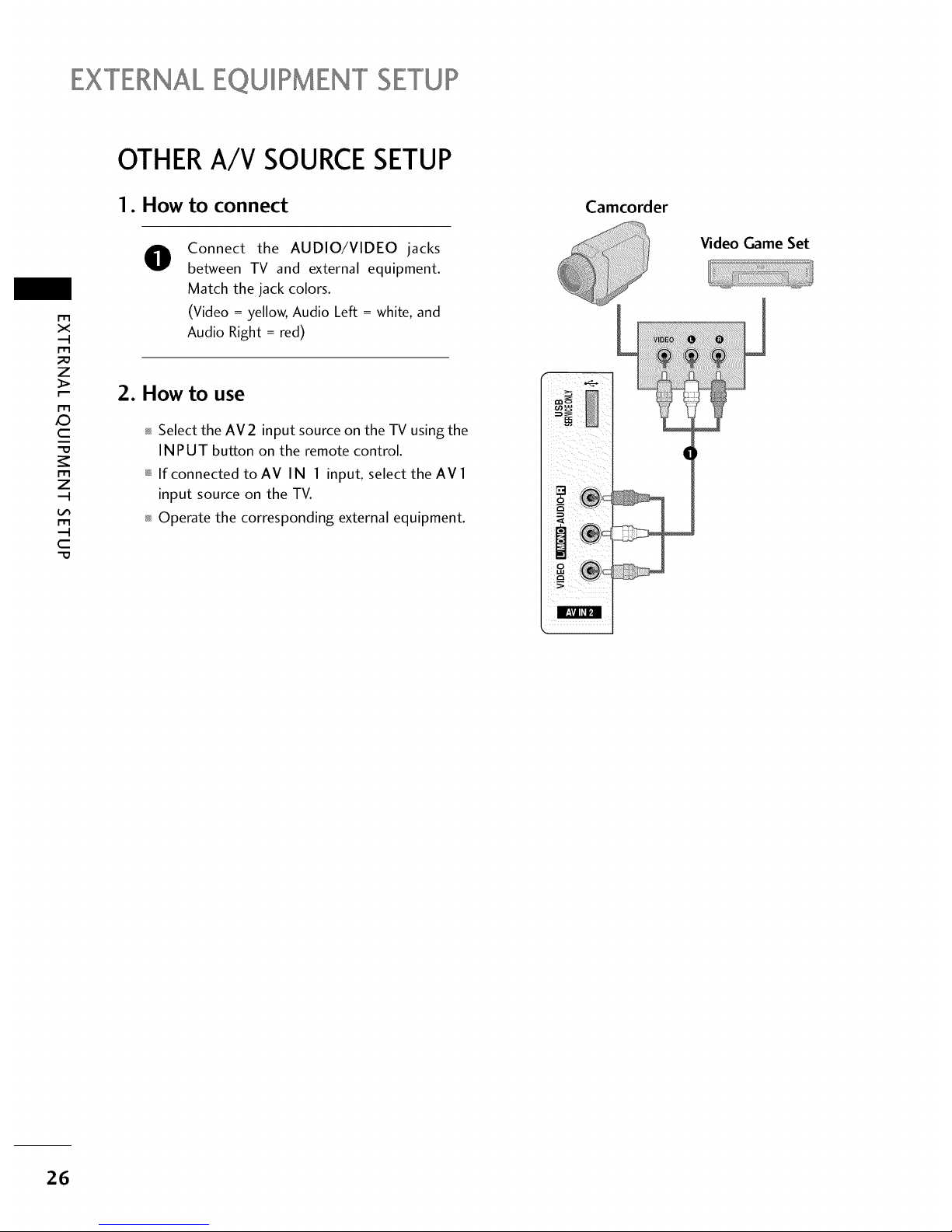
OTHERA/V SOURCESETUP
1. How to connect
@
Connect the AUDIO/VIDEO jacks
between TV and external equipment.
Match the jack colors.
(Video = yellow, Audio Left = white, and
Audio Right = red)
2. How to use
Select the AV2 input source on the TV using the
INPUT button on the remote control.
If connected toAV IN 1 input, select the AVl
input source on the TV.
Operate the corresponding external equipment.
Camcorder
r
Video Game Set
26
Page 28
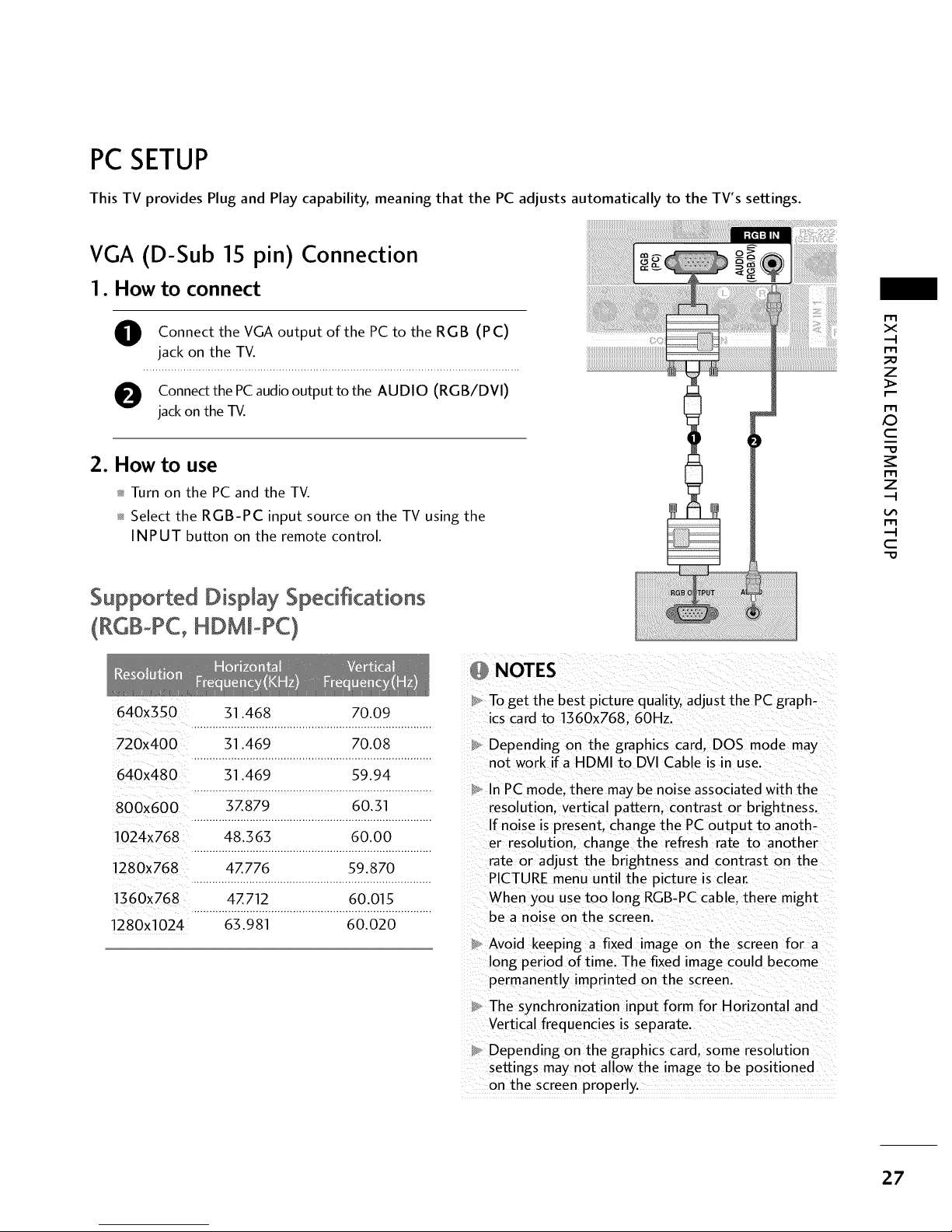
PC SETUP
This TV provides Plug and Play capability, meaning that the PC adjusts automatically to the TV's settings.
VGA (D-Sub 15 pin) Connection
1. How to connect
O onnect the VGA output ofthe PC to the RGB (PC)
jack on the TV.
O Connectthe PCaudiooutput to the AUDIO (RGB/DVI)
jackon the TV.
2. How to use
Turn on the PC and the TV.
Select the RGB-PC input source on the TV using the
INPUT button on the remote control.
Supported Display Specifications
(RGB°PC, HDM[oPC)
640x3SO 31.468 70.09
720x400 31.469 70.08
640X480 31.469 59.94
800x600 3Z879 60.31
1024x768 48.363 60.00
1280x768 4Z776 59.870
1360x768 4Z712 60.015
1280X1024 63.981 60.020
NOTES
To get the best picture quality, adjust the PCgraph-
ics card to 1360x768.60Hz.
Depending on the graphics card. DOS mode may
not work if a HDMI to DVI Cable is in use.
In PC mode. there may be noise associated with the
resolution, vertical pattern, contrast or brightness.
If noise is present, change the PC output to anoth-
er resolution, change the refresh rate to another
rate or adjust the brightness and contrast on the
PICTURE menu until the picture is clear.
When you use too long RGB-PC cable, there might
be a noise on the screen.
Avoid keeping a fixed image on the screen for a
long period of time. The fixed image could become
permanently imprinted on the screen.
The synchronization input form for Horizontal and
Vertical frequencies is separate.
Depending on the graphics card. some resolution
settings may not allow the image to be positioned
on the screen properly
x
_D
z
X:)
c
z
c
27
Page 29
EXTERNALEQUIPMENT SETUP
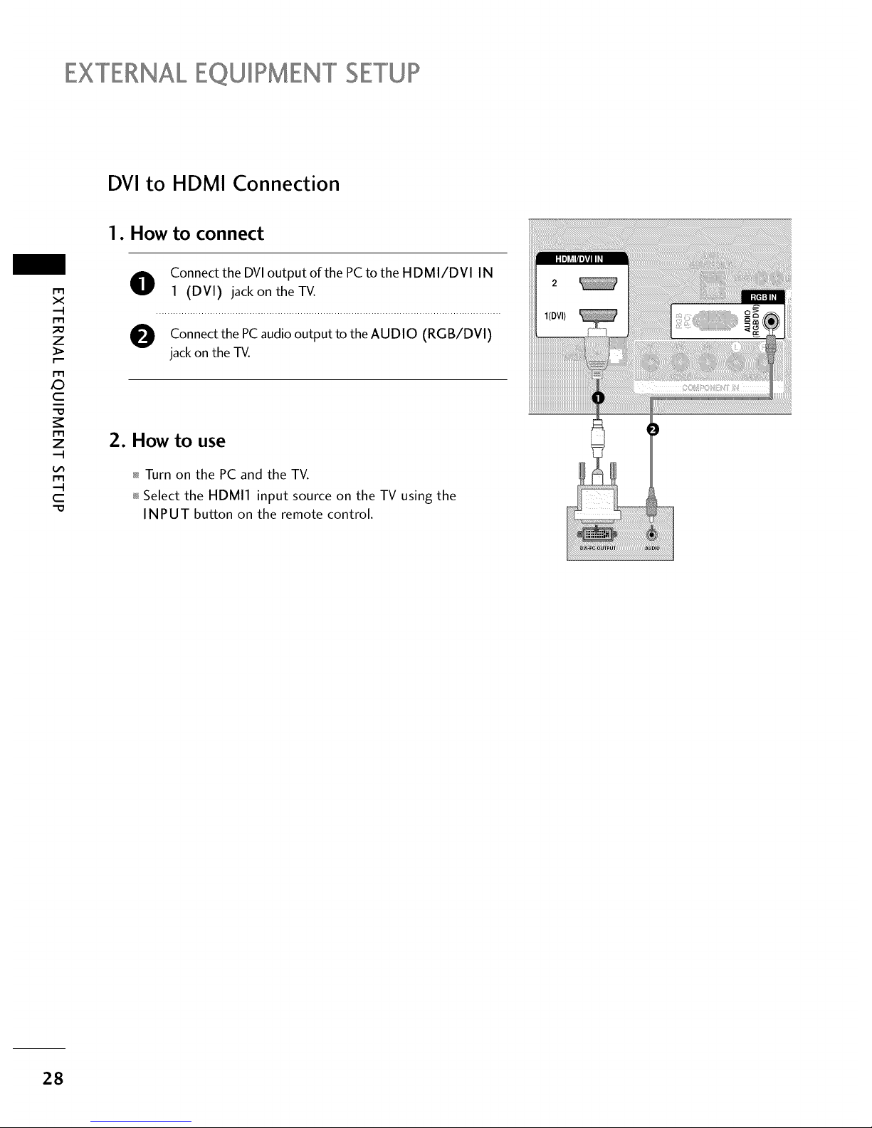
DVI to HDMI Connection
1. How to connect
m
x
m
_o
z
m
X:)
c
"O
m
z
m
c
"O
O onnect the DVI output of the PC to the HDMI/DVI IN
1 (DVI) jack on the TV.
O Connect the PC audio output to the AUDIO (RGB/DVI)
jack on the -IV.
2. How to use
Turn on the PC and the TV.
Select the HDMI1 input source on the TV using the
INPUT button on the remote control.
28
Page 30
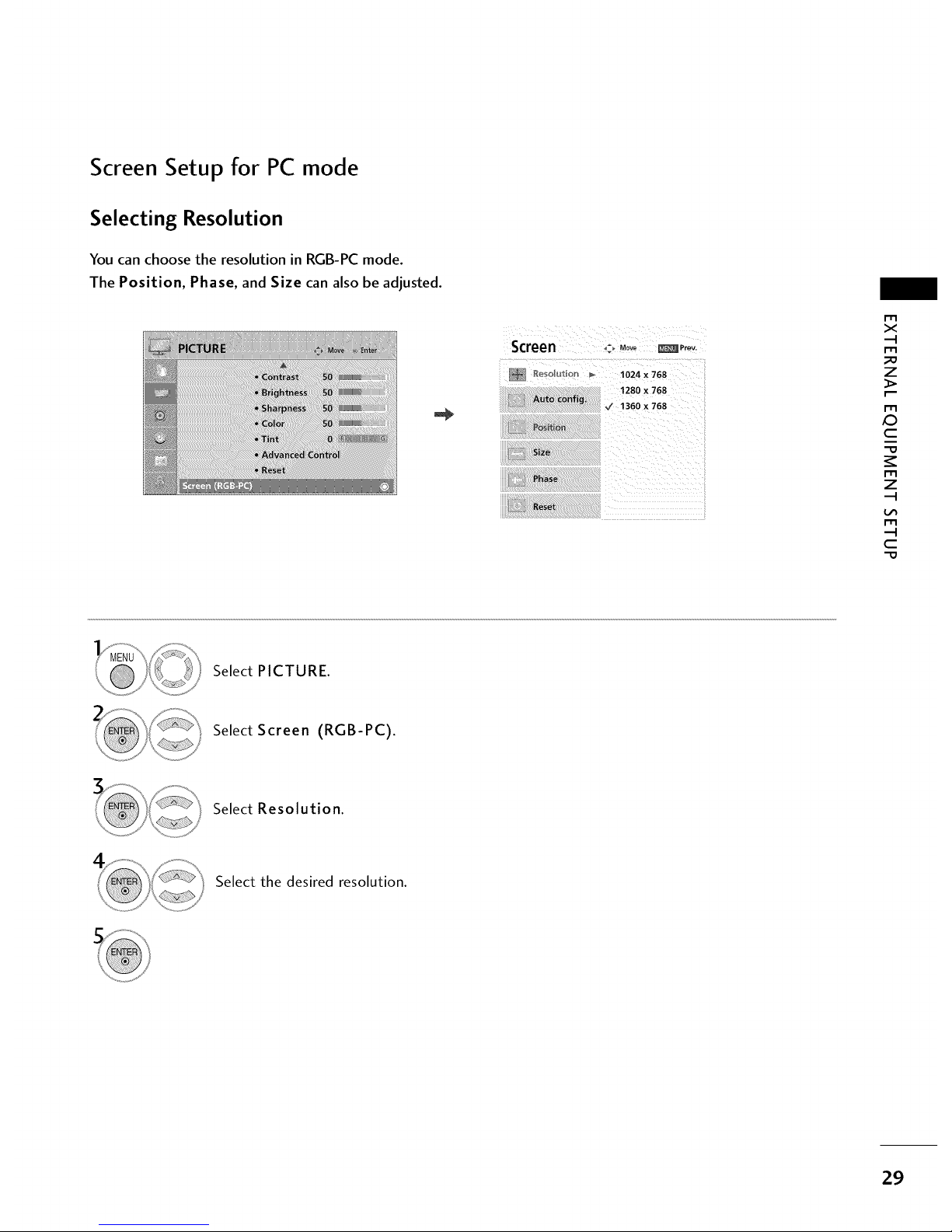
Screen Setup for PC mode
Selecting Resolution
You can choose the resolution in RGB-PC mode.
The Position, Phase, and Size can also be adjusted.
Screen _-_ Move _P ....
_eso_u_: _'_ _ 1024 x 768
m
x
m
_o
z
m
c
"0
m
z
m
c
"0
Select PICTURE.
Select Screen (RGB-PC).
Select Resolution.
Select the desired resolution.
29
Page 31

EXTERNALEQUIPMENT SETUP
Auto Configure
Automatically adjusts picture position and minimizes image instability. After adjustment, if the image is still
not correct, try using the manual settings or a different resolution or refresh rate on the PC.
r'r3
x
m
z
_>
m
c
m
z
m
--4
C
Screen c_Move _ Prey.
Resolution
Auto Config.
Size
Select PICTURE.
Select Screen (RGB-PC).
Select Auto config..
Select Yes.
i...............................................................................................................................................................................................................
• If the position of the image is still not
correct, try Auto adjustment again.
• If picture needs to be adjusted again
after Auto adjustment in RGB-PC, you
can adjust the Position, Size or
Phase.
Start Auto Configuration.
3O
Page 32

Adjustment for screen Position, Size, and Phase
If the picture is not clear after auto adjustment and especially if characters are still trembling, adjust the picture
phase manually.
This feature operates only in RGB-PC mode.
Screen ,:, Move _ P....
!4 Resolution
Autoto,fig.
SiZe
Phase
R_set
r'r3
x
r-r3
z
_>
r-r3
c
"O
r-r3
z
r-r1
c
"O
Select PICTURE.
Select Screen (RGB-PC).
Select Position, Size, or Phase.
Make appropriate adjustments.
Position: This function is to adjust pic-
ture to left/right and up/down as you
prefer.
Size: This function is to minimize any
vertical bars or stripes visible on the
screen background. And the horizontal
screen size will also change.
Phase: This function allows you to
remove any horizontal noise and clear or
sharpen the image of characters.
31
Page 33

EXTERNALEQUIPMENT SETUP
m
x
-I
m
z
m
JO
c
m
z
-I
m
-4
C
Screen Reset (Reset to original factory values)
Returns Position, Size, and Phase to the default factory settings.
This feature operates only in RGB-PC mode.
_Prev.
D
Aut
Reset
Select PICTURE.
Select Screen (RGB-PC).
Select Reset.
Select Yes.
32
Page 34

AUDIO OUT CONNECTION
Send the TV's audio to external audio equipment via the Audio Output port.
Digital
1. How to connect
O Connect end of the coaxial cable theoptical
one or to
TV's OPTICAL port of DIGITAL AUDIO OUT.
O Connect the other end of the coaxial cable to
optical
or
the digital audio input on the audio equipment.
O
Set the "TV Speaker option - Off" in the AUDIO menu. (I_,
p.63). See the external audio equipment instruction manu-
al for operation.
!iili i!i!i
m
x
m
_D
z
m
O
c
m
z
m
c
NOTE
When connecting with external audio equipment, such as
amplifiers or speakers, you can turn the TV speakers off in
the menu. (_, p.63)
CAUTION
Do not look into the optical output port. Looking at the
laser beam may damage your vision.
Audio with ACP(Audio Copy Protection) function my
block digital audio output.
33
Page 35

WATCHING TV / CHANNEL CONTROL
REMOTECONTROL FUNCTIONS
When using the remote control, aim it at the remote control sensor on the TV.
N
-r
z
<
N
I
>
z
z
fT1
N
©
Z
©
POWER
TV/STB/DVDA/CR
GUIDE
PORTAL
INFO
Turns your TV or any other programmed equipment on
or off, depending on mode.
Select the remote's operating mode: TV, STB, DVD, or
VCR.
Displays and removes electronic channel guide.
Displays and removes hotel interactive menu.
Display information about current event.
NUMBER
button
-- (DASH)
FLASH BACK
VCR/DVD
control buttons
PIP
RATIO
TIMER
Navigate the on-screen menus and adjust the system set-
tings to your preference.
Used to enter a program number for multiple program
channels such as 2-1,2-2, etc.
Tune to the last channel viewed.
Control video cassette recorders or DVD players.
Switchesthe sub picture Double Window or off mode.
Change the aspect ratio, t__ p.46
Select the amount of time before your TV turns off auto-
matically, t__ p.74
PIPCH +/-
PIPSWAP
PIPINPUT
SAP 0 Analog mode: Selects MTS sound (Mono, Stereo, or a
SAP) t_ p.65
<_DTV mode: Changes the audio language.
Changes the PIP channel.
Exchange the main/sub images.
Select the connected input source for the sub-picture.
RETURN
REMOVE
_--II •
34
Page 36

THUMBSTICK Navigate the on-screen menus and adjust the system settings to your preference.
(Up/Down/Left
Right/ENTER)
RETURN Clears all on-screen displays and returns to TV viewing from any menu.
MENU Displays the main menu.
INPUT External input modes rotate in regular sequence: TV, AV1-2, Component, RGB-PC,
HDMI1 and HDMI2.
VOLUME UP
/DOWN
CC
MUTE
CHANNEL
UP/DOWN
Increase/decrease the sound level.
Select a closed caption, t__p.68
Switch the sound on or off. t__ p.36
Select available channels.
PAGE Move fromone full set of screeninformation to the next one.
UP/DOWN
-r
z
<
N
-r
>
Z
Z
fT1
N
©
Z
©
Installing Batteries
Open the battery compartment cover on the back side and install
the batteries matching correct polarity (+with +.-with -).
Install two 1.5V AAA batteries. Don't mix old or used batteries with
new ones.
Close cover.
35
Page 37

WATCHING / CHANNELCONTROL
TURNINGON TV
_h
-r"
z
<
N
I
>
z
z
fT1
N
©
Z
©
@
First, connect power cord correctly.
At this moment, the TV switches to standby mode.
_ In standby mode to turn TV on, press the (5/I button on the TV or press
the POWER button on the remote control.
Select the the INPUT button the remote control.
viewing by
source
using
on
This TV is programmed to remember which power state it was last set to,
even if the power cord is out.
When finished using the TV, press the POWER button on the remote control.
The TV reverts to standby mode.
_ If you intend to be away on vacation, disconnect the power plug from the wall power outlet. .................
CHANNEL SELECTION
Press the CH(A or v ) or NUMBER buttons to select a channel number.
VOLUMEADJUSTMENT
Adjust the volume to suit your personal preference.
Press the VOL (+ or -) button to adjust the volume.
If you want to switch the sound off, press the MUTE button.
You can cancel the Mute function by pressing the MUTE or VOL (+ or -)
button.
36
Page 38

ON-SCREENMENUSSELECTION
Your TV's OSD (On Screen Display) may differ slightly from that shown in this manual.
-r"
z
<
N
-r"
>
Z
Z
fT1
N
0
Z
_m
0
Display each menu.
Select a menu item.
Enter to the pop up menu.
Return to TV viewing.
37
Page 39

WATCHING TV / CHANNEL CONTROL
CHANNELSETUP
Auto Scan (Auto Tuning)
Automatically finds all channels available through antenna or cable inputs, and stores them in memory on the
channel list.
Run Auto Tuning again after any Antenna/Cable connection changes.
_h
-r"
z
<
N
-r"
>
Z
Z
fT1
N
0
Z
_m
0
Select CHANNEL.
Select Auto Tuning.
Select Yes.
_ A password is required to gain access to
Auto Tuning menu if the Lock System is
turned on.
Run Auto tuning.
Return to the previous menu.
Return to TV viewing.
38
Page 40

Add/Delete Channel (Manual Tuning)
If selecting DTV or CADTV input signal, you can view the on-screen signal strength monitor to see the quality
of the signal being received.
Select CHANNEL.
-r"
z
c_
<
N
-r"
>
Z
Z
N
0
Z
0
Select Manual Tuning.
Select DIGITAL or ANALOG.
Select channel you want to add
or delete.
A password is required to gain access to
Manual Tuning menu if the Lock System
is turned on.
Select Add or Delete.
Return to the previous menu.
Return to TV viewing.
39
Page 41

WATCHING TV / CHANNEL CONTROL
Channel Editing
The channels in the Custom List are displayed in black and the channels deleted from the Custom List are dis-
played in gray.
Once a channel is highlighted you can add or delete the channel by referring to the small window at the top-
right corner of the screen.
z
<
N
I
>
z
z
fT1
N
©
Z
©
Select CHANNEL.
Select Channel Edit.
Select a channel.
Select channel you want to add or delete.
Return to the previous menu.
Return to TV viewing.
40
Add/Delete ® T.... St Move CH_i Move Page Previous _a Exit
Page 42

CHANNELLABEL
Choose preset labels for your channels.
If a channel label is provided on the signal from the broadcasting station, the TV displays a short name for a
channel even if you didn't preset a label for the channel.
Select CHANNEL.
Select Channel Label.
-r"
z
c_
<
N
-r
>
Z
Z
fT1
N
0
Z
0
Select Channel.
Select a channel to set logo.
Select the appropriate logo for the channel.
Return to the previous menu.
Return to TV viewing.
41
Page 43

WATCHING l°V / CHANNEL CONTROL
INPUTLIST
N
-r
z
<
N
I
>
z
z
fT1
N
©
Z
©
Select the desired input source.
TV
t
HDMI2
_, AV1 _, AV2
l..I HoM,11_-I R_B-PCl_'IComponentI
_ TV: Select it to watch over-the-air, cable
and digital cable broadcasts.
_ AVl -2: Select them to watch a VCR or
other external equipment.
_Component: Select them to watch
DVD or a Digital set-top box.
_ RGB-PC: Select it to view PC input.
HDMI1-2: Select them to watch high
definition devices.
42
Page 44

EXAMPLEELECTRONICPROGRAMGUIDE
This is an example of a typical TV electronic program guide showing available programming.
--CHANNEL INDICATOR
Currently tuned channel
and program.
TV PROGRAM
Current program on select-
ed channel.
-- PROGRAMMING GRID
Program listings arranged in
time slots.
DATE/TIME OSD
Shows current Date/Time.
K&M Kids Movies
Mon. 29 May 2009 11:07
Channel 01:30 AM 2:30 AM 2:45 AM 3:00 AM
" " il il
117 XYZ 1[On The Political Scene
119PQX llTopFashions
12oWBD IIWorld Events Today
Kids ...
I
I
I
II Kids...I
II I
EVENT CHANNEL SELECTION
RT[L INFO
Po
CHANNEL LIST
Shows available
channels in numerical
order.
PROGRAM TITLES
Highlight a title and press
Enter to display additional
program information.
FEATURED ATTRACTION
Highlight and click to get
expanded information.
-r"
Z
c_
<
N
-r
>
Z
Z
fT1
N
0
Z
0
Select GUIDE button to shows available TV programs.
Return to TV viewing.
43
Page 45

PICTURE CONTROL
PIP(PICTURE-IN-PICTURE)
PIP enables the end user to view two sources on the screen at the same time. The end user can switch
between the Main and Sub picture sizes.
N
c
_D
m
N
©
Z
_D
©
Note: Actual size of Main screen and PIP inset may be different than
shown above.
PIP
Turns PIP mode on and off.
PIP CH4-
Selects next higher channel
for PIP window.
PIP CH---
Selects next lower channel
for PIP window.
I
PIP Operation
1. Connect auxiliary source(s) to TV
connections panel.
2. Enter Installer menu to be sure
source(s) is enabled.
3. Use the interactive remote provided
in the room to operate PIR
4. Press PIP on remote.
Use the PIP function keys to
operate the available PIP features.
5. To exit PIP mode, simply press PIR
PIP INPUT
Selects viewing source for PIP
window.
PIP SWAP
Switches Main screen and
PIP window sources.
44
Page 46

PIP Operation
Use the PIP function keys to operate the available PIPfeatures.
Press PIP on remote to place PIP screen inset on the TV screen. See above.
1. With PIP active_ press Swap to switch the PIP inset with the TV picture. See above.
Once the PIP inset shows the TV tuner picture_ you can select TV channels with PIP Ch-I- for channel up
and PIP Ch- for channel down.
2. Press PIP Input to choose from available Aux sources that can be used for the PIP inset.
Note: Not all Aux sources can be used with PIP function.
To exit PIP mode press PIP to return to normal one source viewing.
¢h
c
_e
rT1
¢h
©
Z
_e
©
45
Page 47

PICTURECONTROL
PICTURESIZE (ASPECTRATIO) CONTROL
This feature lets you choose the way an analog picture with a 4:5 aspect ratio is displayed on your TV.
0i_RGB-PC input source use 4:5 or 16:9 aspect ratio.
"0
N
C
_o
m
N
0
Z
_o
0
Press the RATIO button repeatedly to select the picture options
:Set By Program, 4:5, 1 6:9, Zoom1, Zoom2, Just Scan.
Return to TV viewing.
_You can also adjust Aspect Ratio in
the PICTURE menu.
46
Page 48

Set by program
Selectsthe proper picture proportion to match
the source'simage.
(4:3"-_ 4:3)
(16:9"* 16:9)
4:3
Choose 4:3 when you want to view a picture
with an original 4:3 aspect ratio.
16:9
Adjust the picture horizontally, in a linear pro-
portion to fill the entire screen.
-O
N
C
_o
m
N
©
Z
_o
©
47
Page 49

PICTURECONTROL
-O
(h
C
_o
m
(h
©
Z
_o
©
Zoom 1
Choose Zoom 1 when you want to view the pic-
ture without any alteration. However, the top and
bottom portions of the picture will be cropped.
f
m m
I...................... ..u
Zoom 2
Choose Zoom 2 when you want the picture to be
altered, both vertically extended and cropped.
The picture taking a halfway trade off between
alteration and screen coverage.
just Scan
Normally the edges of video signals are cropped
1-2%. Just Scan turns off this cropping and
shows the complete video.
Notes: If there is noise on the edges of the original
signal, it will be visible when Just Scan is activated.
Just Scan operates only with
DTV/CADTV/H DM I-DTV/DVI- DTV
(720p/1080i/1080p),
Component(720p/1080i) input sources.
48
Page 50

PRESETPICTURESETTINGS
Picture Mode - Preset
There are factory presets for picture settings available in the user menus. You can use a preset, change each
setting manually.
Select PICTURE.
Select Picture Mode.
Select Intelligent Sensor, Vivid,
Standard, Cinema, Sport or Game.
0_When selecting Intelligent Sensor,
the most suitable picture isautomatically
adjusted according to the surrounding
conditions.
01_Vivid, Standard, Cinema, Sport, and
Game Settings are preset for the opti-
mum picture quality at the factory and
are not adjustable.
c
_D
r_
0
z
_D
0
Return to the previous menu.
Return to TV viewing.
49
Page 51

PICTURECONTROL
Color Tone - Preset
Choose one of three automatic color adjustments. Set to warm to enhance hotter colors such as red, or set to
cool to see less intense colors with more blue.
"0
N
C
N
0
Z
0
Select PICTURE.
Select Advanced Control.
Select Color Temperature.
Select Cool, Medium, or Warm.
Return to the previous menu.
Return to TV viewing.
5O
Page 52

MANUALPICTUREADJUSTMENT
Picture Mode - User Mode
Adjust the picture appearance to suit your preference and viewing situations.
This feature is disable in "Picture Mode-Intelligent Sensor".
Select PICTURE.
"0
N
C
m
N
0
Z
0
Select Picture Mode.
Select Vivid, Standard, Cinema, Sport or Game.
Select Back Light, Contrast, Brightness,
Sharpness, Color, or Tint.
Make appropriate adjustments.
Return to the previous menu.
Return to TV viewing.
51
Page 53

PICTURECONTROL
PICTUREIMPROVEMENTTECHNOLOGY
Fresh Contrast: Optimizes the contrast automatically according to the brightness of the reflection.
Fresh Color: Adjusts the color of the reflection automatically to reproduce as close as possible natural colors.
Noise Reduction: Removes interference up to the point where it does not damage the original picture.
Gamma: High gamma values display whitish images and low gamma values display high contrast images.
"O
N
C
m
N
O
Z
O
Select PICTURE.
Select Advanced Control.
Select Fresh Contrast, Fresh Color,
Noise Reduction, or Gamma.
Select your desired options.
Return to the previous menu.
Return to TV viewing.
52
Page 54

ADVANCED CONTROL- BLACK (DARKNESS) LEVEL
Adjusting the contrast and the brightness of the screen using the black level of the screen.
This feature is disable in DTV and RGB-PC mode.
"O
_h
C
_o
m
_h
©
Z
_o
©
Select PICTURE.
Select Advanced Control.
Select Black Level.
Select Low or High.
01_Low: The reflection of the screen gets
darker.
01_High: The reflection of the screen gets
brighter.
01_Auto: Realizing the black level of the
screen and set it to High or Low auto-
matically.
Return to the previous menu.
Return to TV viewing.
53
Page 55

PICTURECONTROL
ADVANCEDCONTROL- EYECARE
Dims extremely bright pictures.
This feature is disabled in "Picture Mode-Vivid, Cinema".
c
_D
m
©
z
_D
©
Select PICTURE.
Select Advanced Control.
Select Eye Care.
Select On or Off.
Return to the previous menu.
Return to TV viewing.
54
Page 56

ADVANCED CONTROL- FILM MODE
Set up the TV for the best picture appearance for viewing movies.
When you operate Film Mode (3:2 Pull-Down Mode or Cinema Correction Mode), the TV will adjust 24 fps
video from movies to 30 fps video for display.
This feature operates only in TV (Analog TV, Digital DTV), AVl, AV2, Component 480i/1080i, and HDM11080i
mode.
-O
N
C
_o
m
N
O
Z
_o
O
Select PICTURE.
Select Advanced Control.
Select Film Mode.
Select On or Off.
Return to the previous menu.
Return to TV viewing.
55
Page 57

PICTURECONTROL
PICTURERESET
Settings of the selected picture modes return to the default factory settings.
"O
N
C
m
N
O
Z
O
Select PICTURE.
Select Reset.
Initialize the adjusted value.
Return to TV viewing.
56
Page 58

SOUND & LANGUAGE CONTROL
AUTO VOLUME LEVELER(AUTO VOLUME)
Auto Volume makes sure that the volume level remains consistent whether you are watching a commercial or a
regular TV program.
Select AUDIO.
Select Auto Volume.
Select 0 n or Off.
Return to the previous menu.
0
C
z
z
C
1-11
N
0
z
.-I
0
Return to TV viewing.
57
Page 59

SOUND &LANGUAGE CONTROL
PRESETSOUND SETTINGS (SOUND MODE)
Sound Mode lets you enjoy the best sound without any special adjustment as the TV sets the appropriate
sound options based on the program content.
Standard, Music, Cinema, Sport, and Game are preset for optimum sound quality at the factory and are
not adjustable.
0
c
Z
z
c
l'rl
N
0
Z
.-I
0
Select AUDIO.
Select Sound Mode.
Select Standard, Music,
Cinema, Sport, or Game.
Return to the previous menu.
Return to TV viewing.
58
Page 60

SOUND SETTING ADJUSTMENT- USERMODE
Adjust the sound to suit your taste and room situations.
Select AUDIO.
Select Sound Mode.
Select Standard, Music,
Cinema, Sport, or Game.
0
c
z
_o
z
c
l'rl
N
0
Z
.-I
0
Select Treble or Bass.
Make appropriate adjustments.
Return to the previous menu.
Return to TV viewing.
S9
Page 61

SOUND &LANGUAGE CONTROL
SRS TRUSURROUND XT
Takes advantage of any multi-channel format without needing to add extra speakers or equipment. Dialog
clarity, bass enrichment, and the addition of stereo audio enhancement produces an immersive sound experi-
ence from standard stereo material.
0
c
Z
z
c
l'rl
N
0
Z
.-I
0
Select AUDIO.
Select SRS TruSurround XT.
Select On or Off.
Return to the previous menu.
Return to TV viewing.
6O
Page 62

CLEARVOICE
By differentiating the human sound range from others, it improves the sound quality of voices.
Select AUDIO.
Select Clear Voice.
Select 0 n or Off.
Return to the previous menu.
f_If you select "Clear Voice-On", SRS
TruSurround XT feature will not work.
0
c
z
_o
z
c
l'rl
N
0
Z
.-I
0
Return to TV viewing.
61
Page 63

SOUND &LANGUAGE CONTROL
BALANCE
Adjust the left/right sound of speaker to suit your taste and room situations.
0
c
Z
_o
z
c
l'rl
N
0
Z
.-I
0
Select AUDIO.
Select Balance.
Make appropriate adjustments.
Return to the previous menu.
Return to TV viewing.
62
Page 64

TV SPEAKERSONIOFF SETUP
Turn the TV speakers off if using external audio equipment.
Select AUDIO.
Select TV Speaker.
Select 0 n or Off.
0
c
Z
_o
z
c
l'rl
N
0
Z
.-I
0
Return to the previous menu.
Return to TV viewing.
63
Page 65

SOUND &LANGUAGE CONTROL
AUDIO RESET
Settings of the selected Sound Mode return to the default factory settings.
0
c
Z
z
c
l'rl
N
0
Z
.-I
0
Select AUDIO.
Select Reset.
Initialize the adjusted value.
Return to TV viewing.
64
Page 66

STEREO/SAPBROADCASTSETUP
For Analog only: This TV can receive MTS stereo programs and any SAP (Secondary Audio Program) that accom-
panies the stereo program if the station transmits an additional sound signal. Mono sound is automatically used
if the broadcast is only in Mono.
Each time you press the SAP button,
Mono, Stereo, or SAP appear in turn.
Return to TV viewing.
_lf other languages available on the digital signal,
select them with the SAP button.
0
c
Z
z
c
l'rl
N
0
Z
.-I
0
6S
Page 67

SOUND &LANGUAGE CONTROL
AUDIO LANGUAGE
Other languages may be available if a digital signal is provided by the broadcasting station.
This feature operates only in DTV mode.
0
c
Z
_o
z
c
l'rl
N
0
Z
.-I
0
Select OPTION.
Select Language.
Select Audio.
Select your desired language:
English, Spanish, or French
Return to the previous menu.
Return to TV viewing.
66
Page 68

ON-SCREEN MENUS LANGUAGE SELECTION
The menus can be shown on the screen in the selected language.
Select OPTION.
Select Language.
Select Menu.
Select your desired language.
From this point on, the on-screen menus
will be shown in the selected language.
0
c
Z
z
c
l'rl
N
0
Z
.-I
0
Return to the previous menu.
Return to TV viewing.
67
Page 69

SOUND &LANGUAGE CONTROL
CAPTION MODE
Caption must be provided to help people with hearing loss watch TV.
This feature operates only in TV, AV1-2 mode.
Select Caption On or Off. 01_When selecting Off, Sub-menus for
Analog, DTV, and Digital Option
become disabled.
O
c
Z
z
c
l'rl
N
0
Z
.-I
0
Analog Broadcasting System Captions
Captions provided to help people with hearing loss watch TV. Select a caption mode for displaying captioning
information if provided on a program. Analog caption displays information at any position on the screen and is
usually the program's dialog. Caption/Text, if provided by the broadcaster, would be available for both digital
and analog channels on the Antenna/Cable. This TV is programmed to memorize the caption/text mode which
was last set when you turned the power off. This function is only available when Caption Mode is set On.
Select OPTION.
Select Caption.
Select O n.
Select CC1-4 or Text1-4.
Return to the previous menu.
CAPTION
The term for the words that scroll across
the bottom of the TV screen; usually the
audio portion of the program provided
for the hearing impaired.
TEXT
The term for the words that appear in a
large black frame and almost cover the
entire screen; usually messages provided by
the broadcaster.
Return to TV viewing.
68
Page 70

Digital Broadcasting System Captions
Choose the language you want the DTV Captions to appear in.
Other Languages can be chosen for digital sources only if they are included on the program.
This function in only available when Caption Mode is set On.
Select OPTION.
Select Caption.
Select 0 n.
0
c
z
z
c
l'rl
N
0
Z
.-I
0
Select CC1-4, Text1-4, or
Service1 - 6.
Return to the previous menu.
Return to TV viewing.
69
Page 71

SOUND &LANGUAGE CONTROL
Caption Option
Customize the DTV captions that appear on your screen.
This function in only available when Caption Mode is set On.
0
c
Z
_o
z
c
l'rl
N
0
Z
.-I
0
_!!!!!!!!!!!!!!!!!!!!!!!!!!!!!!!!!!!!!!!!!!!!!!!!!!!!!!!!!!!!!!!!!!!!!!!!!!!!!!!!!!!!!!!!!!!!!!!!!!!!!!!!!!!!!!!!!!!!!!!!!!!!!!!!!!!!!!!!!!!!!
Select OPTION.
Select Caption.
Select 0 n.
Select Digital Option.
Select Custom.
Customize the Style, Font, etc., to your
preference. A preview icon is provided at
the bottom of the screen, use it to see the
caption language.
01_Size: Set the word size.
01_Font: Select a typeface for the text.
0_Text Color: Choose a color for the
text.
01_Text Opacity: Specify the opacity
for the text color.
01_Bg (Background) Color: Select a
background color.
01_Bg (Background) Opacity: Select
the opacity for the background color.
011_Edge Type: Select an edge type.
01_Edge Color: Select a color for the
edges.
Return to the previous menu.
Return to TV viewing.
70
Page 72

TIME SETTING
CLOCK SETTING
Auto Clock Setup
The time is set automatically from a digital channel signal.
The digital channel signal includes information for the current time provided by the broadcasting station.
Set the clock manually if the current time is set incorrectly by the auto clock function.
Select TIME.
Select Clock.
m
z
Select Auto.
Select your viewing area time zone.
: Eastern, Central, Mountain, Pacific,
Alaska, or Hawaii.
Select Auto, Off, or 0 n (depending on whether
or not your viewing area observes Daylight Saving
time).
Return to the previous menu.
Return to TV viewing.
71
Page 73

TIME SETTING
Manual Clock Setup
If the current time setting is wrong, set the clock manually.
m
m
z
c_
Select TIME.
Select Clock.
Select Manual.
Select the Year, Month, Date, Hour, or Minute option.
Set the Year, Month, Date, Hour, or Minute option.
Return to the previous menu.
Return to TV viewing.
72
Page 74

AUTO ON/OFF TIMESETTING
This function operates only if the current time has been set.
The Off Time function overrides the On Time function if they are both set to the same time.
The TV must be in standby mode for the On Time to work.
!iii iiiii _Wiiiiiii_ii_iiiiiii!!li_iiiiiiiiiiiiiiiiiiiiiiiiiiiiiiiiiiiiiii!iiiiiiiiiiiiiii_iiiii!iHi_,ii,,,i_
iii!iiiiiilliiiii:i:llii!ilii!llii!llii!llii!ll!Iliiiii iiiii
Select TIME.
Select Off Time or On Time.
z
c_
Select Repeat.
Select Off, Once, Everyday, Mon~Fri,
Mon~Sat, Sat~Sun, or Sunday.
Select and set Hour or Minute.
Return to the previous menu.
Return to TV viewing.
73
Page 75

TIME SETTING
SLEEPTIMER SETTING
The Sleep Time turns the TV off at the preset time.
Note that this setting is cleared when the TV is turned off.
m
m
z
C_
Press the TIMER button repeatedly to select the number of minutes.
Sleep timer options: Off, 10, 20, 50, 60, 90, 120, 180, and 240 minutes.
Return to TV viewing.
_You can also adjust Sleep Timer in the TIME
menu.
74
Page 76

AUTO SHUT-OFF SETTING
TV will be automatically turned off, in case of no signal for 15 minutes.
Select TIME.
Select Auto Sleep.
m
m
z
Cl
Select 0 n or Off.
Return to the previous menu.
Return to TV viewing.
75
Page 77

PARENTALCONTROL / RATINGS
Parental Control can be used to block specific channels, ratings and other viewing sources.
The Parental Control Function (V-Chip) is used to block program viewing based on the ratings sent by the broad-
casting station. The default setting is to allow all programs to be viewed. Viewing can be blocked by choosing the
type of the program and the categories. It is also possible to block all program viewing for a time period. To use
this function, the following must be done :
1. Set ratings and categories to be blocked.
2. Specify a password
3. Enable the lock
V-Chip rating and categories
Rating guidelines are provided by broadcasting stations. Most television programs and television movies can be
blocked by TV Rating and/or Individual Categories. Movies that have been shown at the theaters or direct-to-
video movies use the Movie Rating System (MPAA) only.
Ratings for Television programs including made-for-TV movies-
0,_TV-G (General audience) 0,_TV-MA (Mature audience only)
0_TV-PG (Parental guidance suggested) 0_TV-Y (All children)
0,_TV-14 (Parents strongly cautioned) 0,_TV-Y7 (Children 7 years older)
r_l
z
N
O
z
O
z
Ch
SETPASSWORD& LOCKSYSTEM
Setting up Your Password
Set up blocking schemes to block specific channels, ratings, and external viewing sources.
A password is required to gain access to this menu.
Select LOCK.
Input the password.
0101_Enter the password as requested.
f_ The TV is set up with the initial pass-
word "0-0-0-0".
76
Page 78

Lock System
Enables or disables the blocking scheme you set up previously.
Select LOCK.
Input the password.
Select Lock System.
Select 0 n or Off.
Return to the previous menu.
01_When you select 0 n, the Lock System
is enable.
_o
m
z
N
©
z
_o
©
_o
z
Return to TV viewing.
77
Page 79

PARENTALCONTROL/RATINGS
Set Password
Change the password by inputting a new password twice.
m
z
N
0
z
0
z
Ch
Select LOCK.
Input the password.
Select Set password.
Choose any 4 digits for your new password.
As soon as the 4 digits are entered, re-enter
the same 4 digits on the Confirm.
Return to the previous menu.
Return to TV viewing.
78
Page 80

CHANNEL BLOCKING
Blocks any channels that you do not want to watch or that you do not want your children to watch.
_ Select LOCK.
Input the password.
Select Block Channel.
Block/Unblock _ Tune _ Move CH Move Page MENu Prey ous #_ Exit
Select a channel to block or unblock.
Block or unblock a channel.
m
z
N
0
z
0
z
Return to the previous menu.
Return to TV viewing.
79
Page 81

PARENTALCONTROL/RATINGS
MOVIE & TV RATING
Movie Rating (MPAA)
Blocks movies according to the movie ratings limits specified, so children cannot view certain movies. You can
set the ratings limit by blocking out all the movies with the ratings above a specified level. Keep in mind that
the movie ratings limit only applies to movies shown on TV, not TV programs, such as soap operas.
_D
rT1
z
N
©
z
_D
©
_D
z
c_
Select LOCK.
Input the password.
Select Movie Rating.
Select G, PG, PG-1 3, R, NC-1 7,
X, or Blocking Off.
Return to the previous menu.
01.G (General audience)
0101_PG (Parental guidance suggested)
011_PG-13 (Parents strongly cautioned)
0101_R (Restricted)
011_NC-17 (No one 17 and under admitted)
0101_X (Adult only)
0101_Blocking Off (Permits all programs)
If you set PG-13: G and PG movies will
be available, PG-13, R, NC-17 and X will
be blocked.
Return to TV viewing.
8O
Page 82

TV Rating Children
Prevents children from watching certain children's TV programs, according to the ratings limit set. The children
rating does not apply to other TV programs. Unless you block certain TV programs intended for mature audi-
ences in the TV Rating - sub menu, your children can view those programs.
_ Select LOCK.
Input the password.
Select TV Rating-Children.
Select Age or Fantasy Violence.
Select block options.
0101_Age (applies to TV-Y, TV-Y7)
0101_Fantasy Violence (applies to TV-Y7)
m
z
N
O
z
O
z
Return to the previous menu.
Return to TV viewing.
81
Page 83

PARENTALCONTROL/RATINGS
TV Rating General
Based on the ratings, blocks certain TV programs that you and your family do not want to view.
_D
m
z
N
O
z
_D
O
_D
z
Select LOCK.
Input the password.
Select TV Rating-General.
Select Age, Dialogue, Language,
Sex or Violence.
Select block options.
Return to the previous menu.
Return to TV viewing.
01_Age (applies to TV-G,TV-PG,TV-14,TV-
MA).
01_Dialogue-sexual dialogue
TV-PG,TV- 14).
01_Language-adult language
TV-PG, TV-14, TV-MA).
01_Sex-sexual situations (applies to TV-PG,
TV-14, TV-MA).
f_l_Violence (applies to TV-PG, TV-14, TV-
MA).
(applies to
(applies to
82
Page 84

DOWNLOADABLE RATING
This function may become available in the future and will be available only for digital channels.
This function operates only when TV has received Regions Rating data.
T
01_Based on rating table, your TV's OSD
(On Screen Display) may differ slightly
from what is shown in this manual.
ENUV_?_:A
_,; ,_ Select LOCK.
Input the password.
Select Downloadable Rating.
Select desired Downloadable
Rating option.
_D
m
z
O
z
_D
O
_D
z
Select desired option and block it.
Return to the previous menu.
Return to TV viewing.
83
Page 85

PARENTALCONTROL/RATINGS
EXTERNALINPUT BLOCKING
Enables you to block an input.
Select LOCK.
m
z
N
©
z
©
z
Input the password.
Select Input Block.
Select input source.
Select On or Off.
Return to the previous menu.
Return to TV viewing.
84
Page 86

COMMERCIAL MODE SETUP
INTERACTIVETV SETUP
Set up the TV for Gem PPV or Gem Operation without a PPV card
GUIDE PORTAL
RETURN MENU INPUT
@©@
©®©
@®©
PPV GEM-TV Setup
I. Make all connections as required of PPV system.
2. Set TV to default condition.
3. Configure all relevant installer menu items and TV features.
4. Install PPV card. In most cases the PPV card is preprogrammed with the PPV
provider master TV setup.
GEM-TV Setup Without PPV Card
Refer to Commercial Mode Setup on page 88.
1. See installer menu pages and make settings as required for Gem operation.
2. Specify a Gem Start Channel for item 118 that will tell the TV which channel
to tune in for Gem operation.
3. Set TV features on TV Channel, Picture, Audio etc. menus as indicated on
page 88.
Gem Operation Interactive Menu Features
Use the Gem remote provided in the room to operate both interactive menu and
the regular TV features.
Channel Guide
Shows available TV programs. Indicates channel, program start and finish time
and identifies the TV network.
Hotel Information
Shows typical hotel information. Such as photos of Guestroom, Dining, Business
Center, Fitness, Pool, and Facility. And any contributing Partners such as local
schools in co-operation programs with the lodge.
Help
Offers explanation for interactive menu operation with provided IR remote.
Exit
Removes the interactive menu from the screen.
Note: TV clock must be set before Gem data can be downloaded.
N
0
I"1"1
N
0
I-I-I
I-I-I
-t
c
J
8S
Page 87

COMMERCIAL MODE SETUP
INSTALLEROVERVIEW
This is the commercial mode setup guide only.
[_=hV+l'Jl[*]II+[,._L"UliI=I;I+f+l=l+LUJ
Operating Installer Menu
To set up the controls for the TV you will need to know how to
enter the TV Installer menu and make changes to the default val-
ues as required. If necessary, familiarize yourself with the TV
Installer menu and how to make and save changes in the menu.
[lIlII] II+[-_f:_llll=l;t _._]=[+1 [lIlII]
t"h
0
I'rl
N
0
I-I-I
I-I-I
-t
c
LG Installer Remote
You will need an LG Installer remote control similar to the one
shown to the right. The installer remote must have a "Source" but-
ton or its equivalent. The remote shown in this manual has
"INPUT" -- this button serves the purpose of a Source button.
The TV's clonable features need to be set up. This is a critical
step. If the Master TV display panel's clonable features like adding
channel icons or channel labels are not done correctly, then the
cloned TVs will all have problems. Refer to the Owner's Manual for
other TV features: Video, Audio, Closed captions, V-Chip, etc.
TLL-1100A Clone Programmer
The TLL is a very simple cloner to use. It can be set up to clone a
master TV setup and transfer it into a target TV. Cloning is accom-
r -, plished using the TV/Cloner MPI ports for commu-
TV Link
Loader-Demo
5+ 5
TLL1100A
nication. Be sure the Master TV is set up complete-
ly. Cloning is only possible when the TV is tuned
to an Analog channel, not a digital channel.
J
Typical Installer Menu
GUIDE PORTAL
RETURN MENU INPUT
G©@
©®©
@®©
®@@
86
Page 88

INTERACTIVETV OVERVIEW
Gem Interactive TV Notes
GEM-TV Setup for PPV
(Pay-per-view) Operation
A PPV card usually has a chan-
nel lineup included with the
master TV setup. If this is the
case, reset TV to default con-
dition, set any TV features and
installer menu items as
required and then insert the
PPV pre-programmed card into
the MPI slot.
Through the interactive TV, the lodging guest is offered a more complete
venue of lodge services and amenities. Using the TV in the comfort of the
hotel room, the guest can browse the lodge resources available and make
selections quickly. Charges for these offerings are billed at the time of reser-
vation. The Gem TV is connected to the lodge's billing computer.
After the interactive TV is installed, the following hotel and other resources
may be available to the hotel guest, assuming that they are provided by the
lodge.
Interactive Amenities may include the following
_ Hotel Information, News and Events.
Directory Services, (Tourist attractions, Restaurants, etc.)
Reservation Service (Business Meetings, Fitness, SPA, etc.)
Weather, Traffic Information.
Shopping Services (Delivery to Guest Room)
Room Service (Menu Ordering, Memo Service,Morning Wake Up Call, Laundry, etc.)
Ticketing Services.
Check Out Service (in the Guest Room).
Gaming Services.
Email resources, guest can access an email account, etc.
Other offerings as they become available .....
After TV setup, remove the AC
power cord for 15 seconds.
Important!
The TV will take a few minutes
to load electronic program
information. If enough time
has not elapsed for the TV to
acquire EPG data, the TV may
operate erratically; menus
may not work or TV will not
respond to IR remote key
presses.
N
0
I'rl
N
0
I-I-I
I-I-I
-t
c
87
Page 89

COMMERCIAL MODE SETUP
[e]:lf_l',i[_] II_[:_:II!=l:i fd:l_LIJ
[0[_] Ill[._t';lilli:l:] b']:[_l [0[_]
iilM I:t';[t]ld D]=I_:_IJIII [i]i)'A
[03) I:Y.,!_1D71.,I=r_ (i_',4
[@._:) [_]-'11[e],tJ:lltlD):l [O)i
0
I'rl
N
0
I-I-I
I-I-I
-4
C
COMMERCIALMODESETUPFORMASTERTV
This page provides an overview of a Master TV configuration.
Note 1: Disconnect all Aux inputs. Under certain conditions, Auto
Tuning (Channel search) is disabled if there is an Aux input active.
Commercial Mode Setup Procedure
1. Set Installer Menu Items
(Enter TV Installer Menu, see Installer menus for detailed instructions.)
a. Set Installer menu item 11 7 FACT DEFAULT, to 001 and press
ENTER on Installer remote. (This clears all installer menu custom
settings, channel labels / icons etc. and reloads the factory default
settings.)
b. Set Item 005 BAND/AFC.
- Broadcast: set to 000. - HRC: set to 002
- CATV: setto 001. - IRC: setto 003
c. Set item 028 CH OVERIDE to 001. This allows access to chan-
nel search, Auto Tuning and Channel List/Edit options in the
Channel Menu.
d. Set other particular installer items that affect your TV programming
network. Enable/Disable Aux sources, set a Gem Start Channel etc.
e. After all required installer menu item settings have been adjusted,
press ENTER on the remote to remove Installer Menu.
2.
Set Up 13/Features
(Channel, Picture, Audio, Lock, Time, Option, Digital Captions etc.
See TV Clonable options list and TV menus pages.)
3. Run Auto Tuning (Channel Search)
(Search for all available channels.) Go to the Channel menu and
access the Auto Tuning option, follow onscreen instructions.
a. Edit Channel Scan. In the Channel Menu, access Channel Edit
option.
Add/Delete channels per your system requirements.
Note: Physical channel numbers are used to identify Virtual channels.
Add familiar channel trademarks/logos like ABC, CBS, NBC etc. to
the Channel-Time onscreen display. In the Channel menu, select the
Channel Label option. Add identifiable labels (logos) for the end
user to readily know what common networks are available.
4. TransferTV _ to InternalTV Controller:. 2-5-5 + Menu Mode
After the TV channel scan has been edited and channel label icons
added, enter the Installer menu. Once in the Installer menu, press 2-5-
5 and MENU on the remote. This transfers the TV setup to the inter-
nal controller box.
[@3) I:PJ'dT:\t/:11il':!:]il:l [O)i
5. J_lcl_ ChanndLabekfar P_abg _ 2-54+lVlenu Mode
Enter Installer menu, press 2-5-4 and MENU. Add your own custom
text labels to channel onscreen displays. Note: Digital Channels often
have a broadcaster generated label. (See 2-5-4+Menu pages.)
When finished, to exit 2-5-4+Menu mode, press MENU.
Verify TV Setup
At this point, verify that the channel lineup, channel icons and custom
labels are correct. Make sure the TV features are set per your require-
ments. Set item 028 Ch Overide to 000 to lock the channel scan.
After the preceding has been completed, the Master TV setup is ready
to be copied to a Clone Programmer, see cloning options pages.
Typical TV Installer Menu
Adjust the settings for
these Installer Menu Items
DIGITAL 19-3
WXYZ
Custom Text Label 'WXYZ' created in
2-S-4 + Menu (Add Channel Label)
Mode
Set 093 RJPAvailable to 001 if
using a remote jack pack
After Master TV setup has been
completed, set item 028 Ch
Overide to 000.
88
Page 90

MASTERTV PROFILESETUPLEARNING/TEACHING WITH USB
MEMORYCARD
On Master TV, Create Profile and Learn
1. Set up all Master TV features on the menus and do
a Channel Search. Add Channel and Aux Labels etc.
Tune in an analog channel.
2. Plug USB memory card into the USB In port on
Master TV.
3. Press Menu key to open Main menu. Highlight the
Option icon.
4. Press the Left arrow key once, the Option icon on
left side of menu will be highlighted.
5. Press number key '7' a total of 7 times.
6. Access to "Learn From TV".
A. First, Expert Download Menu page will not show
the "Learn From TV". In order to make "Learn From
TV" available, key in the password which is used to
enter Installer Menu. Example 9-8-7-6.
B. By pressing up/down arrow keys(if there is other
menus), place the cursor on Learn From TV, then
press Enter Key.
Z Using Up/Down arrow key, highlight "Learn From
TV", then press Enter.
8. To identify the profile from others, you can change
the last 5 digits. Key in a custom file name, then
press the Enter key.
9. The Learning status will be shown on progress bar.
As soon as learning the current profile is complete,
a message will appear on screen indicating the
learning process is done.
10. Remove the USB memory card.
USB Download Menu
Select a type of sofware to be downloaded:
[UpgradeTVSoftware I
[UpgradePTCSoftware I
[ TeachToTV I
Optional: EditJChange File Name
If necessary, the file name can be edited or changed.
LEARN MODE
Choose the name of the image file:
I 37LG700H_UA_ .TLL J
Learn from TV
Learning current profile from master TV:
I on't remove the USB memory card. I
I D° n°t unplug' I
N
0
I'rl
N
0
I-I-I
I-I-I
-t
c
89
Page 91

COMMERCIAL MODE SETUP
On Target TV, Teach Master TV Profile
1. Plug USB memory card with Master TV Profile setup
into Target TV USB input port.
2. Press Menu key to open Main menu and then high-
light the Option Menu icon.
3. Press the Left arrow key once, this will highlight the
Option icon on left side of menu.
4. Press number key '7', a total of 7 times.
5. Using the Up/Down arrow key, select 'Teach to TV',
then press Enter key.
6. Use Up/Down arrow keys to navigate through pro-
files. Select the profile that you want to install by
highlighting it and pressing the Enter key.
Z Teaching progress will be shown on the progress bar.
As soon as teaching is done, a message will appear
indicating that the teaching process has been com-
pleted.
8. When Teaching is done, Remove the USB memory
card and unplug TV power cord.
9. Reconnect TV power cord. Power the TV On and
the master setup should be resident on the TV.
TEACH MODE
The following software files are found in the memory card.
Select the fileyou want to download to this TV.
Or, Press EXITto cancel the upgrade.
Software File Listin USB Memory
TEACH MODE
Teachingthe selected profile to the TV:
I on't remove the USB memory card. [
I D° n°t unplug! I
1
¢h
0
I'rl
N
0
I-I-I
I-I-I
-t
c
Image shown may differ from your TV.
9O
Page 92

TLL-1100A CLONING CONNECTIONS/LEARNING SETUP
Connections for the TLL-1100A Clone Programmer to Learn the TV Master TV Setup
On Master TV
Set up all Master TV features on the ..................
menus and do a Channel Search.
Add Channel and Aux labels etc. See I _'_A°'°nn:_
previous page. Insert MPI cable into ,
TV MPI port. ', _;_
T
On TLI_-11OOA
1. Turn On the TLL-1100A.
2. Use the Mode button to select
Clone Mode.
3. Use the Left/Right arrow to
select the CBank (1 - 8) to store
the master setup in.
4. Plug the other end of the MPI
cable into the MPI port on the
bottom of the TLL.
5. With the Installer remote control,
select item 1 on TLL menu.
6. Press Enter, to transfer the
Master setup into CBankX on the
TLL The TLL will copy the master
setup.
Z When learning is done, discon-
nect MPI cable from Master TV.
8. Reconnect TV power cord. Power
the TV On and the master setup
should be resident on the TV.
Selected Bank:CBank X Saved
Bi|| i _:_:n,,m= :[o],,l L
(2) TEACH TO TV
(3) SET CLONE CLOCK FROM W
(4) SET W CLOCK FROM CLONE
(5) DISPLAY TV SETUP
(6) DISPLAY CLONE SETUP
CLONE CLOCK =00:00
TV CLOCK=O0:O0
THE CLONEIS VERSION V2.2.2
-To change menuitems, Press
M.P.I. Learning Setup
"~r"
i
m
ODO
D,OQ
i.......
M.P.I. Teaching Setup
_ o_....
~r" I
t T
T.--C7_
oclo
D,,o_Q
A
i
CLONE SELECTION MENU
Selected Bank: CBank X Saved
/1) LEARN FROM TV
lt_Jl i _1':'[11_li itl i
(3) SET CLONE CLOCK FROM TV
(4) SET TV CLOCK FROM CLONE
(5) DISPLAY TV SETUP
(6) DISPLAY CLONE SETUP
CLONE CLOCK = 00:00
TV CLOCK = 00:00
THE CLONE IS VERSION V2.2.2
-To change menu items, Press
channel keys or digits.
-To execute item, Press ENTER.
i
I
On Target TV
1. Connect MPI cable from the TLL
to the MPI port on the Target
TV. Assure that the correct
CBank(X) is selected on TLL..
2. With the Installer remote control
select item 2, to Teach the target
TV the master TV setup.
3. Press Enter to begin teaching.
4. When Teaching is done, discon-
nect MPI cable and power the TV
Off. Unplug TV power cord.
5. Reconnect TV power cord. Power
the TV On and the master setup
should be resident on the TV.
N
0
I'rl
N
0
I"I'1
I-I1
-t
c
91
Page 93

COMMERCIAL MODE SETUP
LT2002 CLONING CONNECTIONS/LEARNING SETUP
Connections for the LT2002 Clone Programmer to Learn the TV Master TV Setup
" % %i / / /
/
t Antenna
or CATV
s
i:
, ii%_ZiJ.
|
I
I
I
I
I
I
I
I
Ferrite Core
(TDK, ZCAT
2035-0930)
Master TV
_r
!
..............................!................................................
MPI
QuickSet II Programmer
LT2002
Crone Programmer
N
0
I'rl
N
0
I-I-I
I-I-I
-t
c
Before you begin cloning...
01_The Master TV should be connected to a good, stable
signal from an over-the-air antenna or cable service
Ana[og channel and connected to power. (See above.)
01_Teaching and Learning is only possible between iden-
tical model devices. (However, the LT2002 Clone pro-
grammer can store up to 3 different 'master' setups.)
WARNING: Copying a blank or incorrect memory into
a TV, STB or other device will cause the TV, STB or
other device to operate erratically or become inopera-
ble.
01_Use an Installer's remote to operate Learning and
Teaching menus.
01_Make sure that the batteries in the Clone programmer
are fresh.
,l_If batteries are removed, the Clone Clock time will be
lost.
,l_Decide if you want to set the time from the Clone
programmer or copy the time to the Clone program-
mer; from a compatible TV which has the clock set to
the current time.
,l_Setting the time and transferring it to the Clone or
other device is a separate procedure.
,l_Follow the connection diagram above to connect the
Clone to a Master TV TV display panel. After learning
is complete, to another identical TV TV display panel
to "teach" it the master setup.
,l_See the Clone Troubleshooting section to resolve
problems.
Turn to the next page to continue Cloning Setup.
92
Page 94

LT2002 CLONINGLEARNINGSETUP
Learning the Master TV Setup
Instructions for the Clone Programmer to Learn the Master TV Setup
Use MPI Cable to Connect LT2002 Clone
Programmer to Master TV MPI Port
If there is a good connection, "THE CLONE HAS
CONTROL OF TV"
messagewill appear. Pressany key on the Installer remote.
Learn Setup from Master TV
Press 1 to select the "LEARN FROM TV" option, then
press ON/OFE POWER, or ENTER to go to the Memory
Bank Selection Menu. Pick the Memory "Bank" you want to
store the master TV's setup in by pressing either Channel
key repeatedly to choose Memory 1,2 or 3. (If you
choose a Memory "Bank" that has a master device's setup
programmed into it, that setup will be overwritten by the
new master TV's setup.) Once the Clone memory bank is
selected, press ON/OFF, POWER, or ENTER. The Clone
memory bank you have selected will be shown. Press
ON/OFF or POWER to begin copying the master TV's
setup.
Set the Clock (Optional)
Set the time on a Master TV's Clock. (If the time has
already been copied from a TV into the Clone programmer,
you can set a master TV's clock by copying the time from
the Clone programmer.) The Clone Programmer can copy
the current time to both a master TV and to the Clone's
internal clock; accurate to within one minute. (Another rea-
son that the Clone programmer should be equipped with
fresh, high-quality alkaline batteries, isfor it to keep the
time as accurately as possible.)
Since the Clone Programmer's time cannot be set directly,
the current time needs to be copied from a Zenith/LG TV
equipped with M.RI. input capability.
After the time is copied to the Clone programmer, the cur-
rent time can then be transferred to another TV. (This can
be a master TV, or another TV which has already had the
features set up.)
THE CLONE HAS CONTROL OF THE TV
THE CLONE IS VERSION XX
THE TV IS VERSION XX
THE SW IS REVISION XX
CLONE CLOCK= XX:XX
TV CLOCK= XX:XX
-PRESS ANY KEY TO CONTINUE.
-DISCONNECT CLONE WHEN DONE.
I
This menu should appear by itself after
the LT2002 is connected to the TV MPI
port.
CLONE SELECTION MENU
(1) LEARN FROM TV
(2) TEACH TO TV
(3) SET CLONE CLOCK FROM TV
(4) SETTV CLOCK FROM CLONE
(5) DISPLAY TV SETUP
(6) DISPLAY CLONE SETUP
-TO CHANGE MENU ITEMS, PRESS
CHANNEL KEYS OR DIGITS.
-TO EXECUTE ITEM, PRESS ON/OFF,
POWER, OR ENTER
This menu should appear after any key is
pressed on the Installer remote.
LT2002 Clone Programmer Communication
Problems
ll_A slow flashing green light indicates there are
communication problems between the TV and
the LT2002 clone programmer. If this is the
case, check for a damaged cable, poor contacts,
or other connection troubles.
ll_If the status indicator is red, the programmer
batteries are low and should be replaced. Install
4 high-quality alkaline AA batteries.
N
0
I'rl
N
0
I-I-I
I-I-I
-t
c
93
Page 95

COMMERCIAL MODE SETUP
CLONINGCONNECTIONS/TEACHINGSETUP
Teaching the Master Setup to Another TV
Connections for the LT2002 to Teach another TV the Master Setup
_Antenna
_, or CAW
I I
I I
I I
I
i .....
| I
\ /
,s
_"r
I
I I
Target TV
'_" ,s I
QuickSet II Programmer
LTPO02
Crone Programmer
N
0
I'rl
N
0
I-I-I
I-I-I
-t
c
Teach Master TV's Setup to
the target TV
After learning is complete, remove the M.RI. cable from the mas-
ter TV and connect it to the target TV that you want to copy
the master TV's setup into. With "THE CLONE HAS CONTROL
OF TV" message displayed, press 2 or use either Channel key to
go to the "TEACH TO TV" option, press ON/OFE POWER, or
ENTER. Select the LT2002 memory that the new setup is in.
Press On/Off to transfer the new setup and other information to
the new TV. Teaching usually takes 2-3 minutes.
After the "TEACHING COMPLETE" message is displayed, press
any key to return to the Clone menu, then press ON/OFF,
POWER, or ENTER. If finished, detach M.RI. cable from the
target, newly-cloned TV.
Disconnect TV Power for 15 Seconds
Unplug the AC power cord of the newly-cloned TV from the
power outlet for about 15 seconds to activate the newly-copied
setup.
(1) LEARN FROM TV
(2) TEACH TO TV
(3) SET CLONE CLOCK FROM TV
(4) SET TV CLOCK FROM CLONE
(5) DISPLAY TV SETUP
(6) DISPLAY CLONE SETUP
-TO CHANGE MENU ITEMS, PRESS
CHANNEL KEYS OR DIGITS.
-TO EXECUTE ITEM, PRESS ON/OFF,
POWER, OR ENTER
This menu should appear
after any key is pressed
on the Installer remote.
m
TEACHING IN PROGRESS,
PLEASE WAIT
This display will appear
during Teaching function.
TEACHING COMPLETE
This display will appear
after Teaching is complete.
94
Page 96

INSTALLERMENU
Use the Installer's Menu to set up or change operational settings.
See more detailed descriptions of the Installer menu items on the following pages...
Accessing the Installer's Menu
Make sure TV is on. Installer's menu items can be accessed by using
an installer's remote control. Just press MENU repeatedly until the
TV seems to stop responding, then press 9, 8, Z 6, then ENTER to
access the Installer's menu. To remove the Installer's menu, press
ENTER again. Any changes you make will be stored in nonvolatile
memory. (The menu also disappears automatically.)
The Installer's menu opens with item 000 INSTALLER SEQ 000.
Use the Up/Down arrow keys to sequence through the available
menu items. Or, access an item directly by keying in the line number,
then pressing MENU. For example, to access the Sleep Timer option
which is item 015, press 0-1-5, then MENU. To change a setting,
use the Left/Right arrow keys. Or, enter a value directly.
[e]:lf_1",21[_]I_[._f;lilil:l:ilf4:l_[IJ
Using the Installer's Menu
Items 000 - 119 are immediately accessible only upon entering the
Installer's Menu. Their numbers, descriptions, ranges, factory default
settings, and a place for listing any changes made on-site are given
below and on the following pages.
Typical Installer Menu
Activating changes made to the Installer's Menu
After exiting the Installer menu, power the TV off and then back on to activate changes to the Installer menu.
Installer Menu Items OOO through 034
Menu Item
000
001
002
003
004
OO5
007
OO8
OO9
010
011
015
016
017
021
022
O23
O28
O29
030
031
O32
O34
Function
INSTALLER SEQ
POWER MANAGE
AC ON
BAND/AFC
STRT CHANNEL
CHAN LOCK
STRT VOLUME
MIN VOLUME
MAX VOLUME
MUTE DISABLE
KEY DEFEAT
SLEEPTIMER
EN TIMER
ALARM
V-CHIP
MAX BLK HRS
CAPTION LOCK
CH. OVERIDE
OLD OCV
ACK MASK
POLL RATE
TIMING PULSE
CAMPORT EN
Value Range
0-3
0-7
0/1
0-3
0 - 12Z 255
0/1
0 - 63,255
0 - 63
0 - 63
0/1
0/1
0/1
0/1
0/1
0/1
0- 99
0/1
0/1
0/1
0/1
20- 169
186 - 227
0/1
Default Value
0
0
0
1
255
0
255
0
63
0
0
1
0
1
1
12
0
1
0
0
94
207
1
Brief Description of Function and Comments
Leave default set to 0.
Sets number of hours of no activity before auto shut Off.
Set to 1 to enable auto turn On at power up.
Selects Tuning Band: 0=Broadcast, 1=CATV, 2=HRC, 3=IRC
Channel at turn-on (Set to 255 to tune in last channel before power Off).
If set to 1, cannot tune from current channel.
Sets Volume levelat TV turn-on (Set 255 to retain last volume level).
Sets minimum allowable volume setting.
Sets maximum allowable volume setting.
Set to 1 to disable mute function.
Set to 1 to disable menu navigation keys on display panel.
Set to 1 to enable Sleep Timer.
Set to 1 to enable On/OffTimers.
Set to 1 to enable Alarm.
Set to 1 to enable V-Chip functions.
Sets number of V-Chip (Parental Control) blocking hours.
Set to 1 to retain caption setting at power Off.
If set to 0, limits direct access to favorite channels.
Set to 1 to change M.P.I.operation to OCV.
If set to 1, changes M.RI. for some OCV boxes.
Selects poll rate for M.RI.
Sets baud rate for M.RI.
Set to 1 to enable Video 2 input.
N
0
I'rl
N
0
I-I-I
I-I-I
--4
C
-0
95
Page 97

COMMERCIAL MODE SETUP
N
0
I'rl
N
0
I-I-I
I-I-I
-t
C
Installer Menu Items 03S through 119
Menu Item Function Value Range Default Value Brief Description of Function and Comments
035 COMPPORT EN. 0 / 1 1 Note 1. Set to 0 to disable HDMI 1. Set to 1 to enable HDMI 1.
038 YPrPb EN. 0 / 1 1 Set to 1 to enable display panel Component Video 1 input jacks.
039 REAR AUX EN 0 / 1 1 Set to 1 to enable display panel Video 1 input jack.
040 AUTO CAMPORT 0 / 1 1 Set to 1 to automatically switch to Camport. If set to 1, STRT AUX
SRCE cannot be set to 2.
046 STRT AUX SRCE 1 - 6,255 6 Sets the starting AUX source.
047 AUX STATUS 0 / 1 0 Set to 1 for M.RI. AUX source to be reported as a channel number
instead of Channel O.
053 DIS. CH-TIME M. 0 / 1 0 Set to 1 to disable Channel-Time display.
069 EN. CH-T COL. 0 / 1 1 Set to 1 to enable custom color for the Channel-Time display.
070 FOR. CH-TIME 0 - 7 2 Chooses custom foreground color for the Channel-Time display.
071 BCK. CH-TIME 0 - 7 2 Chooses custom background color for the Channel-Time display.
073 CH NOT AVBLE 0 / 1 0 If set to 1 and channel override is O, "NOT AVAILABLE" message is
displayed when directly accessing a channel not in the favorite channel list.
075 REVERT CH 0 / 1 0 If set to 1 and lossof M.RI.communication occurs,TV tunes to Start Channel.
078 UPN MSB 0 _ 255 0 User programmable number, most significant byte.
079 UPN MSB-1 0 _ 255 0 User programmable number, most significant byte - 1.
080 UPN MSB-2 0 _ 255 0 User programmable number, most significant byte - 2.
081 UPN LSB 0 - 255 0 User programmable number, least significant byte.
082 CHKSM ERROR 0 / 1 1 Enforces rigid M.RI. checksum.
083 HANDSHK TIME 0 _ 5 5 Relaxes M.RI. timing to be compatible with PC based
Windows-controlled systems.
084 PERMANENT BLK 0 / 1 0 Removes block hours setting for Parental Control and makes block
permanent.
087 REAR RGB EN. 0/2/18 2 Note 1. Set to 0 to disable RGB1. Set to 2 for PC.
088 EN NOISE MUTE 0 / 1 1 If set to 1, mutes audio if no signal is present.
090 KEY LOCK 0 / 1 0 If set to 1, keyboard is locked out, IR is still functional.
091 YPrPb2 0 / 1 1 Set to 0 to disable HDMI 2. Set to 1 to enable HDMI 2.
093 RiP AVAILABLE O, 1,2, 5, 6 0 Set to 0 to disable. Set to 1,2, 5 or 6 for HDMI or DVI mode. (See
detailed descriptions)
094 SAP MENU EN 0 / 1 1 Set to 0 to disable feature on Function menu. Set to 1 to enable feature
on Function menu.
096 DEE ASR RATIO 0 _ 5 2 Sets default aspect ratio atpower up. See detailed descriptions
anditem 106.
099 BACK LIGHTING 1 - 100 Sets the brilliance of the TV picture backlighting.
101 - 200 255 Settings above 101 control dynamic back lighting and-enable
201,202, 255 power saving mode.
102 ATSC BAND 0 - 4 4 Selects ATSC band.
103 ATSC TUNE MODE 0 / 1 1 Default 01 for physical channel scan. Set to 0 for Virtual Channel scan.
104 START MINOR CH 0 - 255 0 Selects Minor start channel. Set 0 for NTSC. Not 0, sets Minor
channel number.
106 ASP RATIO LOCK 0 / 1 0 To retain set aspect ratio on power cycle, set to 1. Set to 0 for
default ratio on power cycle.
116 VIDEO MUTE EN 0 / 1 0 Set to 0 for normal, set to 1 for Blank.
117 FACT DEFAULT 0 / 1 0 0=Normal. 1 =Loads presets of all above settings.
118 POWER SAVING 0 / 1 1 Set to 0 to disable power saving mode.
119 GEM STRT CH 0 _ 135 0 Sets the GEM Start Channel.
Note 1: Dependent on item 093 RJPAvailable setting.
96
Page 98

Detailed Descriptions of Installer Menu Items
000 - INSTALLERSEQUENCE
Specifies entry sequence to the Installer Menu.
0 = 9876 1 = 4321
2 = 1478 3 = 3698
001 - POWER MANAGE (Power Management)
Determines hours of no activity before automatic shutoff.
The POWER MANAGE function is for saving energy. If
set to 0, Power Manage is Off. Settings range from 0 - Z
with 1 - 7 representing the hours that the unit will
remain On, unless there has been activity from either the
control panel or remote control.
002 - AC ON (AC Power Switchable)
If set to 1, allows the TV to turn On just by applying
AC power. Pressing the On button is not necessary. This
is desirable if the TV is plugged into a cable box or a
power outlet controlled by a wall switch. Use ADJ
Left/Right arrow to choose 0 or 1 where 0 is the
default is Off, and 1 is On.
NOTE: If set to 1 (On), the TV does not respond to
On/Off commands from either the remote or the dis-
play control panel, and the SLEEP TIMER is also non-
functional.
003 - BAND/AFC (Band/Automatic Frequency
Control)
There are 4 possible settings for this option:
0 = Broadcast 1 = CATV
2 = HRC 3 = IRC
If some channels were not found by Auto Tuning
(Channel Search), select the appropriate Band setting
here and add the channels using the Channel Edit
option in the Channel Menu.
004 - STRT CHANNEL (Start Channel)
If active, this function allows you to determine the initial
channel number when the TV is turned On. This feature
is useful for an in-house information channel, since the
TV would always select that channel when it is turned
On. Setting this to 255 causes the last channel viewed
when the TV was turned Off, to be the tuned to chan-
nel when the TV is turned On again. Note: For a digital
Start Channel, always remember to set item 104 to the
Minor Start Channel number.
255 = Lastchannel 1 _ 125 = Ch X 0 = Aux
126 Map to Channel 3. 127 Map to Channel 4.
OOS - CHAN LOCK (Channel Lock)
CHAN LOCK is ideal if the system must always be on
the same channel. Changing channels with Channel
Up/Down or keypad numbers is impossible. Channel
Lock is inactive if set to 0 (default).
Generally, this feature is used in connection with START
CHANNEL (Installer item 004) where the start channel
may, for example, be set to 3 or 4. If the start channel
is 3, then the TV will remain locked on Channel 3.
NOTE: For Items 007, 008 and 009
For legacy reasons, the scale used is 0 - 63. The PTC
software will translate this to the 0 - 100 scale used by
the TV.
To translate a TV volume level to the installer menu
value, use the following formula:
Installer Value = TV Value x 67;
100
Enter only the whole number (disregard fractions).
007 - STRT VOLUME (Start Volume)
This function allows the Installer to determine the initial
volume level setting when the TV is turned On. This fea-
ture is useful for an in-house information channel, since
the TV would always select that volume level when it is
turned On. The range of values are 0 - 63,255. If 255
is selected, the current volume level will be retained in
memory when the TV is turned Off; at turn On, the vol-
ume level will be automatically set at the previous or
last level.
008 - MIN VOLUME (Minimum Volume)
This function determines the minimum volume level
allowable with the VOLUME (VOL) Up/Down control. In
this way, for example, someone cannot set the volume
too low to hear. The value range is from 0 to 63 --
change values with ADJ Left/Right arrow. The factory
default is 0, which provides the full range of volume
control, if item 009 MAX VOLUME is also set to 63. It
may be best to set the same value on every TV.
NOTE: The minimum volume level cannot have a value
setting higher than the MAX VOLUME level (described
below).
N
0
I'rl
N
0
I-I-I
I-I-I
-t
c
97
Page 99

COMMERCIAL MODE SETUP
N
0
_D
N
0
rll
c
009 - MAX VOLUME (Maximum Volume)
This function determines the maximum volume level
allowable with the VOLUME (VOL) Up/Down controls.
In this way, for example, someone can not set the vol-
ume level high enough to disturb others. The value
range is 0 to 63, with 63 as the default, which gives the
user the full range of volume control, if item 008 MIN
VOLUME is also set at 0. Change values with ADJ
Left/Right arrow keys. It may be best to set the same
value on every TV.
NOTE: The maximum volume level cannot have a value
setting lower than the MIN VOLUME level (described
previously).
010 - MUTE DISABLE
Enables or disables sound mute function. If set to I,
sound cannot be muted. If set to 0, sound can be
muted.
011 - KEY DEFEAT (Keyboard Defeat)
If set to I, key defeat prevents the end user from
accessing the on-screen menus with the display front
panel--MENU, SELECT, and Left / Right arrow keys do
not function. If set to 0, those keys do function.
NOTE: The menus can always be accessed by pressing
MENU on the remote.
01S - SLEEP TIMER
If set to 1, the SLEEP TIMER feature may be used. If
set to O, the Sleep Timer is not available.
016 - EN TIMER (Enable On/Off Timers) *
If set to I, Timer function is available to user and
enabled continuously. Set to 0 to disable On/Off
Timers. (Clock must be set in order to use Timers.)
017 - ALARM *
Gives the installer the option of making the Alarm
function available to the end user. If set to 1, Alarm
function is available to end user. Set to 0 to disable
the Alarm function.
NOTE: Clock must be set before the Alarm function
will work.
021 - V-CHIP (Parental Control) *
Set to 1 to activate V-Chip (Parental Control); have it
available to end user to filter and control or otherwise
restrict programming content that can appear. Set to 0
to turn V-Chip feature Off, not available to user; no
programming restrictions can be set.
022 - MAX BLK HRS (Maximum Block Hours) *
Sets hours from 0 to 99 for the maximum V-Chip
(Parental Control) block hours. Default setting is for
12 blocking hours.
* Only affects Function Menu if enabled by
some PPV providers.
023 - CAPTION LOCK
Set to 1 to restore previous caption On/Off state after
turn Off. If set to 0, captions are always Off at turn
On.
028 - CH. OVERIDE (Channel Override)
If set to I, the user can select channels with either
Channel up/down or by direct keypad entry. If set to
0, only those channels that are entered for scanning
can be selected.
029 - OLD OCV (On Command Video TM)
Set to I for operation with systems from On
Command Corporation.
030 - ACK MASK
M.RI. Communication Parameter. Leave at default set-
ting unless changed by Pay-Per-View provider. When set
to I, changes M.RI. for some OCV boxes.
031 - POLL RATE
M.RI. Communication Parameter. Selects Poll Rate for
M.RI. Leave at default setting unless changed by Pay-
Per-View provider. Step size of 16 ms.
032 - TIMING PULSE
M.RI. Communication Parameter. Leave at default set-
ting unless changed by Pay-Per-View provider. Sets
baud rate. Step size of 4.3 uS.
034 - CAMPORT EN. (Camera Port Enable)
Set to I to enable Video 2 input on display panel. If
set to 0, Video 2 input on display panel is not func-
tional.
NOTE: S-Video overrides Video jack.
03S - COMPPORT EN. (Computer Port Enable)
Enable/disables display panel HDMII input jack. Set to
0 to disable, set to I to enable.
NOTE: The setting above is ignored if Installer item
093 RiP AVAILABLE, is set to I.
038 - YPrPb EN. (Rear Component Video Enable)
Set to I to enable display panel rear Component
Video input jacks.
Set to 0 to disable display panel rear Component
Video input jacks.
039 - REAR AUX EN. (Rear Aux Enable)
Set to I to enable display panel rear AUX (Video I ) input.
Set to 0 to disable display panel rear AUX (Video I )
input.
Note: S-Video overrides Video.
98
Page 100

040 - AUTO CAMPORT
Set to I to automatically switch to Camport when equip-
ment is connected to front Video input.
Set to 0 to disable front Video automatic source selection.
NOTE: If set to I, 093 RJPAvailable is automatically set to 0.
046 - STRT AUX SRCE (Start Aux Source)
Sets the starting AUX source. At power up, TV will tune to
starting Aux source if item 004 Start Channel is set to 0.
If item 093 RIPAvailable is set to 0 and item
040 Auto Camport is set to 0:
I = Video I 4 = RGB 255 = Last Aux
2 = Video 2 5 = HDMI 2
3 = HDMI I 6 = Component
If item 093 RJPAvailableis setat 1:
2 = Video 2 5 = HDMI 2 6 = Component
If item 040 Auto Camport isset to 1:
1 = Video 1 5 = HDMI 2
3 = HDMI 1 6 = Component
4= RGB
047 - AUX STATUS
Set to I for M.RI. AUX source to be reported asa channel
number instead of channel 0. Set to 0 to disable AUX iden-
tification change. Controls M.RI. status channel response for
AUX inputs.
0S3 - DIS. CH-TIME (Disable Channel-Time)
Set to I to disable the Channel-Time display, Channel-Time
display will not appear.
Set to 0 to enable the Channel-Time display.
069 - EN. CH-T COL. (Enable Channel-Time Custom
Color)
Set to I to enable custom color for the Channel-Time dis-
play.
Set to 0 to disable custom color for the Channel-Time dis-
play.
070 - FOR. CH-TIME (Channel-Time Display Foreground
Color)
Set according to Color Chart.
0 = Black 3 = Yellow 6 = Cyan
I = Red 4 = Blue 7 = White
2 = Green 5 = Violet
NOTE: If foreground and background color are the same,
menu background is transparent.
071 - BCK. CH-TIME (Channel-Time Display
Background Color)
Set according to Color Chart.
0 = Black 3 = Yellow 6 = Cyan
1 = Red 4 = Blue 7 = White
2 = Green 5 = Violet
NOTE: If foreground and background color are the same,
menu background is transparent.
073 - CH NOT AVBLE (Channel Not Available)
If set to 1 and item 028 CHANNEL OVERRIDE is set to 0,
"NOT AVAILABLE" message is displayed when directly
accessing a channel not in the channel scan list available in
memory.
O7S - REVERT CH (Revert to Start Channel)
If set to 1 and loss of M.P.I.communication occurs, TV auto-
matically tunes to the specified Start Channel.
078 - UPN MSB (UPN Most Significant Byte)
User programmable number, most significant byte readable
by M.PJ.command. Note: Not linked to serial number.
079 - UPN MSB-1 (UPN Most Significant Byte-1 )
User programmable number, most significant byte-1 read-
able by M.P.I.command. Not linked to serialnumber.
080 - UPN MSB-2 (UPN Most Significant Byte-2)
User programmable number, most significant byte-2 read-
able by M.P.I.command. Not linked to serialnumber.
081 - UPN LSB (UPN Least Significant Byte)
User programmable number, least significant byte readable
by M.PJ.command. Not linked to serial number.
082 - CHKSM ERROR (Checksum Error)
Enforces rigid M.P.I.checksum validation.
Set to 1 for validation.
Set to 0 to disable (does not check checksum on M.P.I.
async port). SPI is always checked.
083 - HANDSHK TIME (Handshake Time)
Adds an additional delay to the handshake time which is 64
msec,thus relaxing M.PJ.timing requirements to be compati-
ble with PC based Windows controlled systems, range is 0 -
5.
(Timeout = 25.5MS + [25.5 MS* Handshake time]).
084 - PERMANENT BLK (Permanent Block)
Allows Lock (Parental Control) blocking schemes to be per-
manent by disabling the blocking hours function.
Set to I to install Parental Control restrictions permanently.
Set to 0 for user-specified hours control of blocking
schemes.
087 - REAR RGB EN. (Rear RGB Enable)
Controls access to rear RGB input on TV.
Set to 0 to disable RGB input.
Set to 2 for PC for STB RGB input.
Set to 18 for Auto Configure one time only with power
cord removal and reinsertion.
088 - EN NOISE MUTE (Enable Noise Mute)
If set to 1, audio mutes if no signal is present.
090 - KEY LOCK
Ifset to 1, display panel keyboard is locked ouL not available
to end user. IR receiver remains functional.
N
0
I'rl
N
0
I-I-I
I-I-I
-t
c
-0
99
 Loading...