

LG 3828W5S6150 Service Manual

삼 흥
정 판
Website: http://biz.lgservice.com
LIGHT OVEN
SERVICE MANUAL
MODEL: MP-9483SL
CAUTION
BEFORE SERVICING THE UNIT, READ THE SAFETY PRECAUTIONS IN THIS MANUAL.
P/NO : 3828W5S6150
“SolarDOM”
MP-1283SL
April, 2005
Printed in Korea

SAFETY PRECAUTIONS
This device is to be serviced only by properly qualified service personnel.
Consult the service manual for proper service procedures to assure continued safety operation and for precautions to be
taken to avoid possible exposure to excessive microwave energy.
PRECAUTIONS TO BE OBSERVED BEFORE AND
DURING SERVICING TO AVOID POSSIBLE
EXPOSURE TO EXCESSIVE MICROWAVE ENERGY
A) Do not operate or allow the oven to be operated with the door open.
B) Make the following safety checks on all ovens to be serviced before activating the magnetron or other
microwave source, and make repairs as necessary; (1) interlock operation, (2) proper door closing, (3)
seal and sealing surfaces (arcing, wear, and other damage), (4) damage to or loosening of hinges and
latches, (5) evidence of dropping or abuse.
C) Before turning on microwave power for any service test or inspection within the microwave generating
compartments, check the magnetron, wave guide or transmission line, and cavity for proper alignment,
integrity, and connections.
D) Any defective or misadjusted components in the interlock, monitor, door seal, and microwave generation
and transmission systems shall be repaired, replaced, or adjusted by procedures described in this manual
before the oven is released to the owner.
E) A microwave leakage check to verify compliance with the Federal Performance Standard should be
performed on each oven prior to release to the owner.
CAUTION
MICROWAVE RADIATION
DO NOT BECOME EXPOSED TO RADIATION FROM THE MICROWAVE GENERATOR
OR OTHER PARTS CONDUCTING MICROWAVE ENERGY.

CONTENTS
(Page)
SAFETY PRECAUTIONS
SPECIFICATIONS
CAUTIONS
---------------------------------------------------------------------------------------------------------------
INSTALLATIONS
-----------------------------------------------------------------------------------------------------
------------------------------------------------------------------------------------------------------
OPERATING INSTRUCTIONS
FEATURES
CONTROL PANEL
OPERATING SEQUENCE
SCHEMATIC DIAGRAM
CIRCUIT DESCRIPTION
------------------------------------------------------------------------------------------------------------------------
SERVICE INFORMATION
TOOLS AND MEASURING INSTRUMENTS
MICROWAVE LEAKAGE TEST
MEASUREMENT OF MICROWAVE POWER OUTPUT
----------------------------------------------------------------------
------------------------------------------------------------------------------------
--------------------------------------------------------------------------------------------------------------
----------------------------------------------------------------------------------------------------
------------------------------------------------------------------------------------------------------
-----------------------------------------------------------------------------------------------------
-------------------------------------------------------------------------------------------
---------------------------------------------------------------------------
--------------------------------------------------------------------------------------------
Inside front cover
1-1
2-1
3-1
4-1
4-1
4-1
4-2
4-3
4-4
5-1
5-1
5-1
-----------------------------------------------------------
5-3
DISASSEMBLY AND ADJUSTMENT
UPPER & LOWER HEATER
INTERLOCK CONTINUITY TEST
COMPONENT TEST PROCEDURE
TROUBLE SHOOTING
EXPLODED VIEW
-----------------------------------------------------------------------------------------------------
-------------------------------------------------------------------------------------------------
------------------------------------------------------------------------------------------------------
REPLACEMENT PARTS LIST
-------------------------------------------------------------------------------------
------------------------------------------------------------------------------------------
--------------------------------------------------------------------------------------
5-3
5-7
5-8
5-9
5-14
6-1
------------------------------------------------------------------------------------
7-1
SPECIFICATIONS
Front Plate
ITEM
MODEL
Power Requirement
Power Output
Microwave Frequency
Magnetron
Timer
Outside Dimensions
Cavity Dimensions
Net Weight
Shipping weight
Control Complement
DESCRIPTION
MP-9483SL / MP-1283SL
120 Volts AC 60 Hz
Single phase, 3 wire grounded
Microwave 1550W
Grill Max 1300W
Convection 1680W
900 Watts full microwave power (IEC60705)
2450 MHz
2M214 -240GP
0 ~ 90 min.
527 (W) x 392 (H) x 480 (D) mm
440 (W) x 204 (H) x 420 (D) mm
28 kg
31 kg
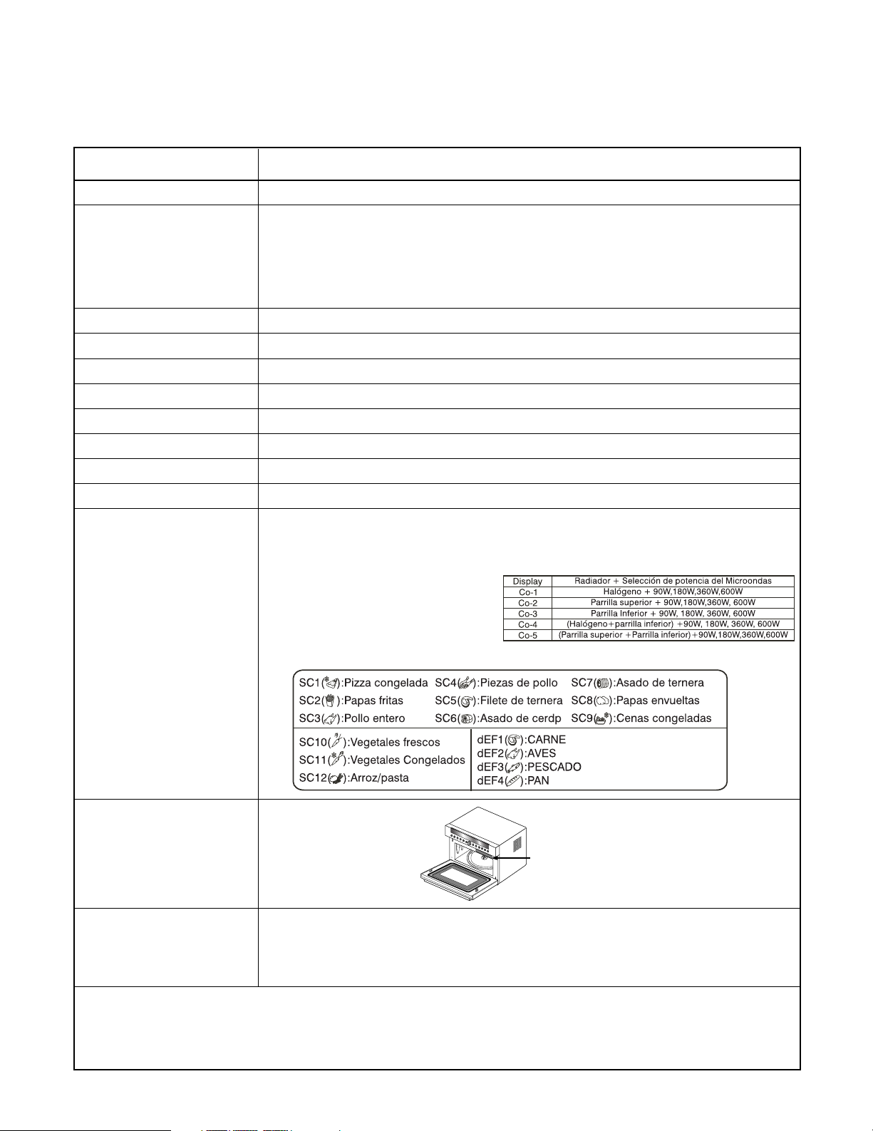
1. Microwave Power level: 3. Convection: 40°C, 100~230°C
MAX (900W), 600W, 360W, 180W, 90W
2. GRILL 4. SPEED COMBI
Upper Sheath Heater (1200W)
5.SPEED AUTO COOK
Rating Label Location
Accessories
This oven is designed for household use only.
It is not recommended for commercial purposes.
Owner's manual
High rack, Low rack
Metal tray
1-1
CAUTIONS
Unlike other appliances, the microwave oven is
high-voltage and high-current equipment.
Though it is free from danger in ordinary use,
extreme care should be taken during repair.
• DO NOT operate on a 2-wire extension cord during
repair and use.
• NEVER TOUCH any oven components or wiring during
operation.
• BEFORE TOUCHING any parts of the oven, always
remove the power plug from the outlet.
• For about 30 seconds after the oven stops, an electric
charge remains in the high voltage capacitor. When
replacing or checking, you must discharge the high
voltage capacitor by shorting across the two terminals
with an insulated screwdriver.
MICROWAVE RADIATION
Personnel should not be exposed to the
microwave energy which may radiate from the
magnetron or other microwave generating
device if it is improperly used or connection.
All input and output microwave connections,
waveguide, flange and gasket must be secure
never operate the device without a microwave
energy absorbing load attached.
Never look into an open waveguide or antenna
while the device is energized.
• Proper operation of the microwave oven requires that
the magnetron be assembled to the waveguide and
cavity. Never operate the magnetron unless it is
properly installed.
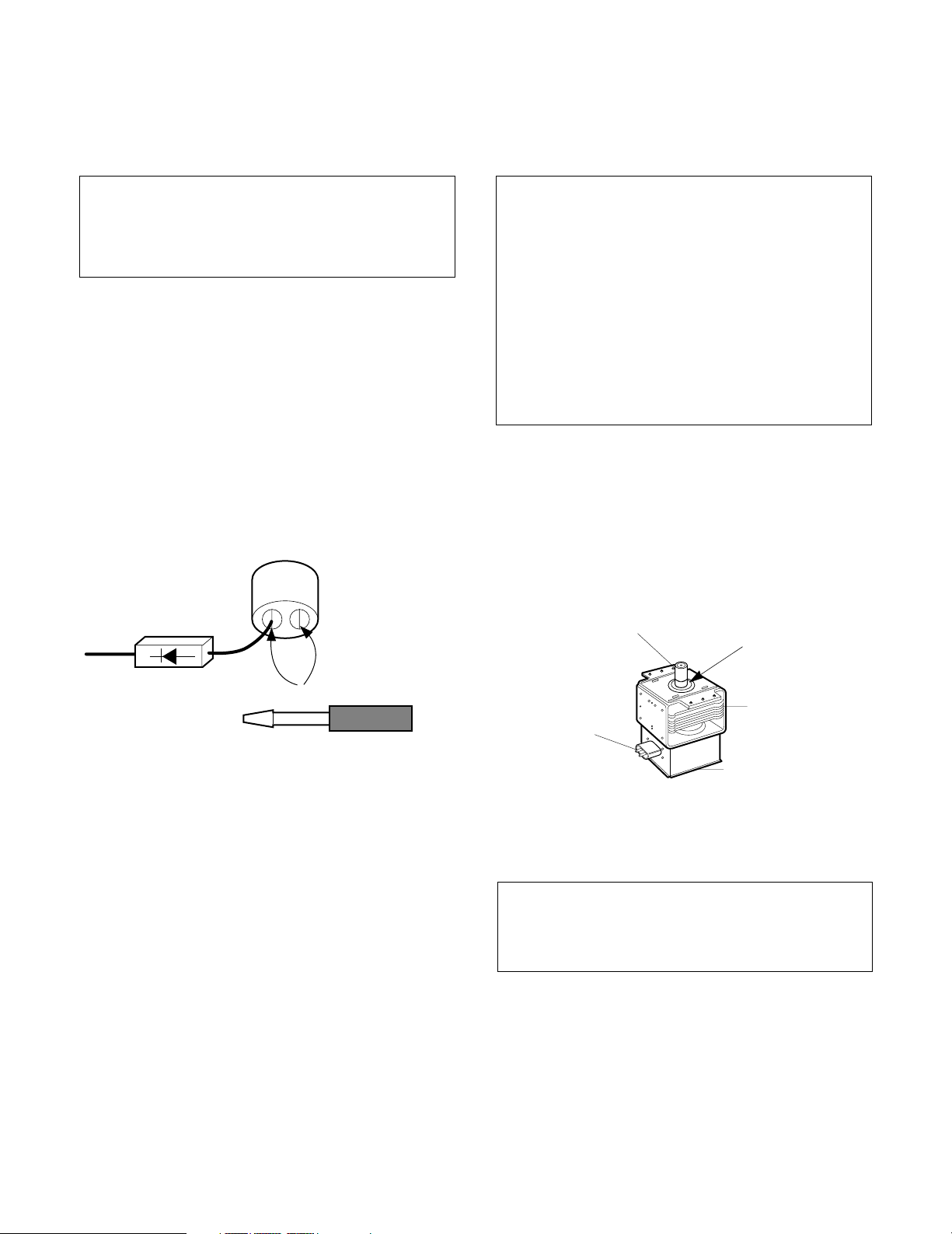
• Be sure that the magnetron gasket is properly
installed around the dome of the tube whenever
installing the magnetron.
ANTENNA
Gasket
•
Remove your watches whenever working close to or
replacing the Magnetron.
• NEVER operate the oven with no load.
• NEVER injure the door seal and front plate of the oven
cavity.
• NEVER put iron tools on the magnetron.
• NEVER put anything into the latch hole and the
interlock switches area.
COOLING FIN
FILAMENT
TERMINALS
MAGNETRON
CHASSIS GROUND
MAGNETRON
THE OVEN IS TO BE SERVICED ONLY
BY PROPERLY QUALIFIED SERVICE
PERSONNEL.
2-1
INSTALLATIONS
BEFORE YOU BEGIN, READ THE FOLLOWING INSTRUCTIONS COMPLETELY AND CAREFULLY.
INSTALLING
1. Empty the microwave oven and clean inside it with
a soft, damp cloth. Check for damage such as
misaligned door, damage around the door or dents
inside the cavity or on the exterior.
2. Put the oven on a counter, table, or shelf that is
strong enough to hold the oven and the food and
utensils you put in it. (The control panel side of the
oven is the heavy side. Use care when handling.)
3. Do not block the vent and the air intake openings.
Blocking vent or air intake openings can cause
damage to the oven and poor cooking results.
Make sure the microwave oven legs are in place to
ensure proper air flow.
4. The oven should not be installed in any area where
heat and steam are generated, because they may
damage the electronic or mechanical parts of the
unit.
Do not install the oven next to a conventional
surface unit or above a conventional wall oven.
5. Use microwave oven in an ambient temperature
less than 104°F(40°C).
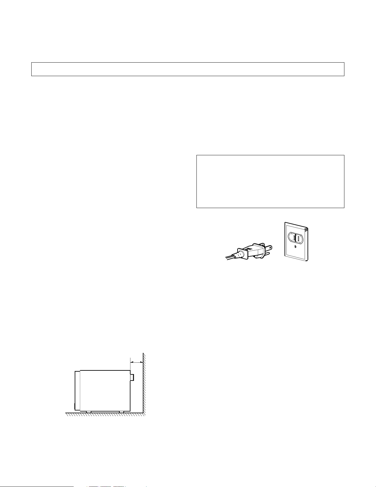
GROUNDING INSTRUCTIONS
For personal safety,this appliance must be fully
grounded at all times.
In the event of an electrical short circuit, grounding
reduces the risk of electrical shock.
The plug must be plugged into an outlet that is
properly installed and grounded.
WARNING
Improper use of the grounding plug can result in a
risk of electric shock.
Do not, under any circumstances, cut or remove
the third ground prong from the power cord plug.
PREFERRED METHOD
INSURE PROPER GROUND
EXISTS BEFORE USE
6. Place the microwave oven on a sturdy and flat
surface at least 10 cm(4 inches) from the wall.
7. Place the microwave oven as far away as possible
from TV, RADIO, COMPUTER, etc., to prevent
interference.
10cm
3-1
OPERATING INSTRUCTIONS
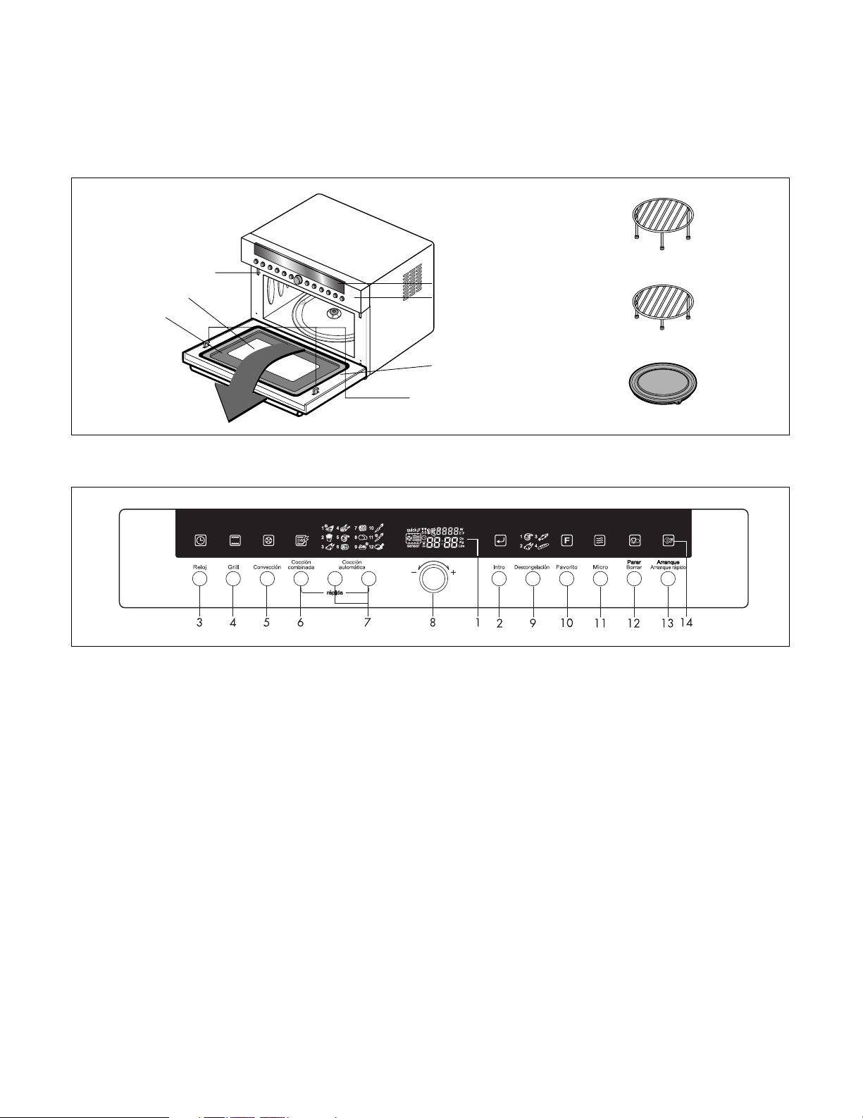
Control Panel Deco.
Control Panel
Oven Front Plate
Window Door Screen
Door Frame
HIGH Rack
LOW Rack
Metal Tray
Choke Cover
Safety Door Lock System
FEATURES
CONTROL PANEL
1. Display Window: You can show time of day, cooking time, power
level and cooking categories.
2. Enter: You can determine the selected cooking category, microwave
power level or temperature.
3. Clock: You can set the time of day.
4. Grill: You can select the grill categories.
5. Conv.: You can select temperature and time of convection.
6. Speed Combi: You can select the combination categories.
7. Speed Auto Cook: Speed auto cook allows you to cook most of your
favorite food quickly by selecting the food type and the weight of the
food.
8. Dial Knob:
• You can set cooking times, temperature, weight and cooking
categories.
• While cooking with auto and manual function, you can lengthen or
shorten the cooking time at any point by turning the dial knob(except
defrost mode).
9. Defrost: You can select the food type and the weight of the food.
10. Favorite: The cooking program can be stored in the memory of your
oven up to 9 modes(FA-1~FA-9).
11. Micro: You can select five power level settings.
12. Stop/Clear: You can stop over and clear all entries except time of day.
• Press Stop/Clear Button one time, all icons will be displayed on
window in time of day or clear mode.
• Press Stop/Clear Button one more time, all icons will be disappeared.
13. Start/Quick Start:
• In order to start cooking which is selected, press button one time.
• The quick start feature allows you to set 30 seconds intervals of HIGH
power cooking with a touch of the quick start button.
14. Icon: You can see all icons by pressing “Stop/Clear” button one time
and remove all icons by pressing one more time(all icons will disappear
automatically after 15 seconds).
Blink will guide to next step for setting while cooking, the icon of the
selected cooking mode will be displayed on window.
4-1
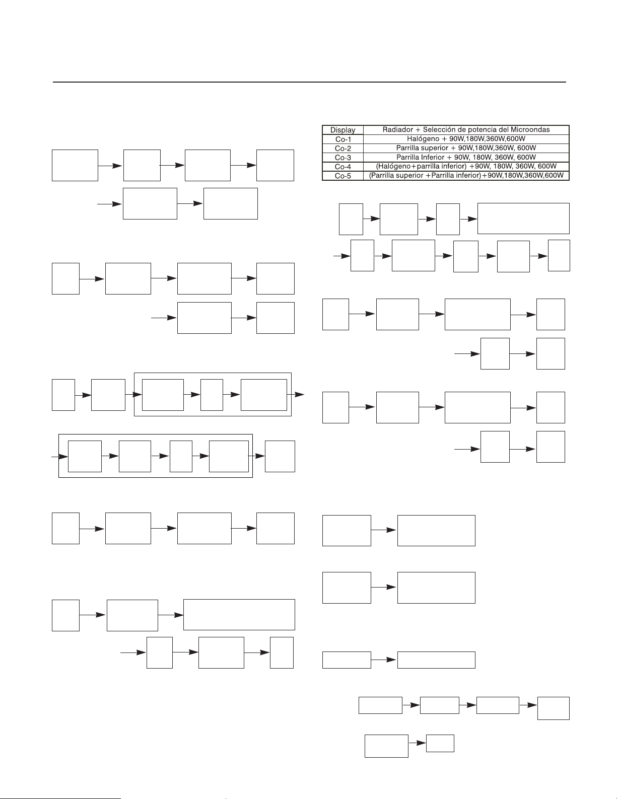
OPERATING SEQUENCE
The following is a description of component functions
during oven operation.
1. SETTING THE CLOCK
Stop/Clear Clock
Turn Dial
Desired
minute
Turn Dial
Desired
hour
Enter
Enter
2. MICROWAVE COOKING
Stop/
Clear
Function
MWO
3. MULTI STAGE COOKING
Stage 1
Stop/
Clear
Function
MWO
Turn Dial
Desired
power level
Stage 2
Turn Dial
Desired
power level
Turn Dial
Desired
cooking time
(MICROWAVE)
Enter
Enter
Start
Turn Dial
Desired
cooking time
6. SPEED COMBI COOKING
*Speed combi Categories
Grill & Convection & Speed Combi
ex)
Stop/
Clear
Enter
Function
Combi-4
Desired
power
level
Enter
temp(40°C, 100°C~230°C)
Enter
7. DEFROST
Stop/
Clear
Function
Defrost
Turn Dial
Desired defrost
category
Food
weight
8. SPEED AUTO COOK
Stop/
Clear
Fuction
Auto
cook
Turn Dial
Desired auto
cook category
Turn Dial
Desired convection
Desired
cooking
time
Start
Enter
Start
Enter
Function
MWO
Desired
power
level
Enter Start
4. GRILL COOKING
Stop/
Clear
Function
Grill
Turn Dial
Desired
cooking time
5. CONVECTION COOKING
To cook
Stop/
Clear
Function
Convection
Enter
Desired convection
temp(40°C, 100°C~230°C)
Desired
cooking
Desired
cooking
time
Turn Dial
time
Start
Start
Food
weight
Start
9. CHILD LOCK
This oven has a CHILD LOCK feature.
To Set CHILD LOCK
Stop/Clear
To Cancel CHILD LOCK ※ Approximately
Stop/Clear
Stop/Clear
(Touch and Hold)
4 Seconds
Stop/Clear
(Touch and Hold)
10. QUICK START
Stop/Clear Start/Quick Start
11. FAVORITE (MEMORY COOK)
To set
Stop/Clear Favorite
Any mode
Favorite
(FA-1)
4-2
To cook
Favorite
(FA-1)
Start
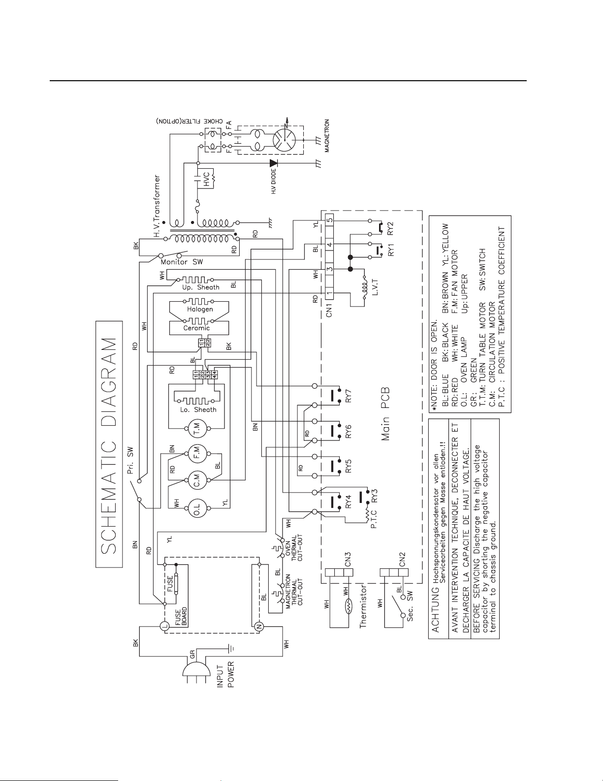
SCHEMATIC DIAGRAM
4-3
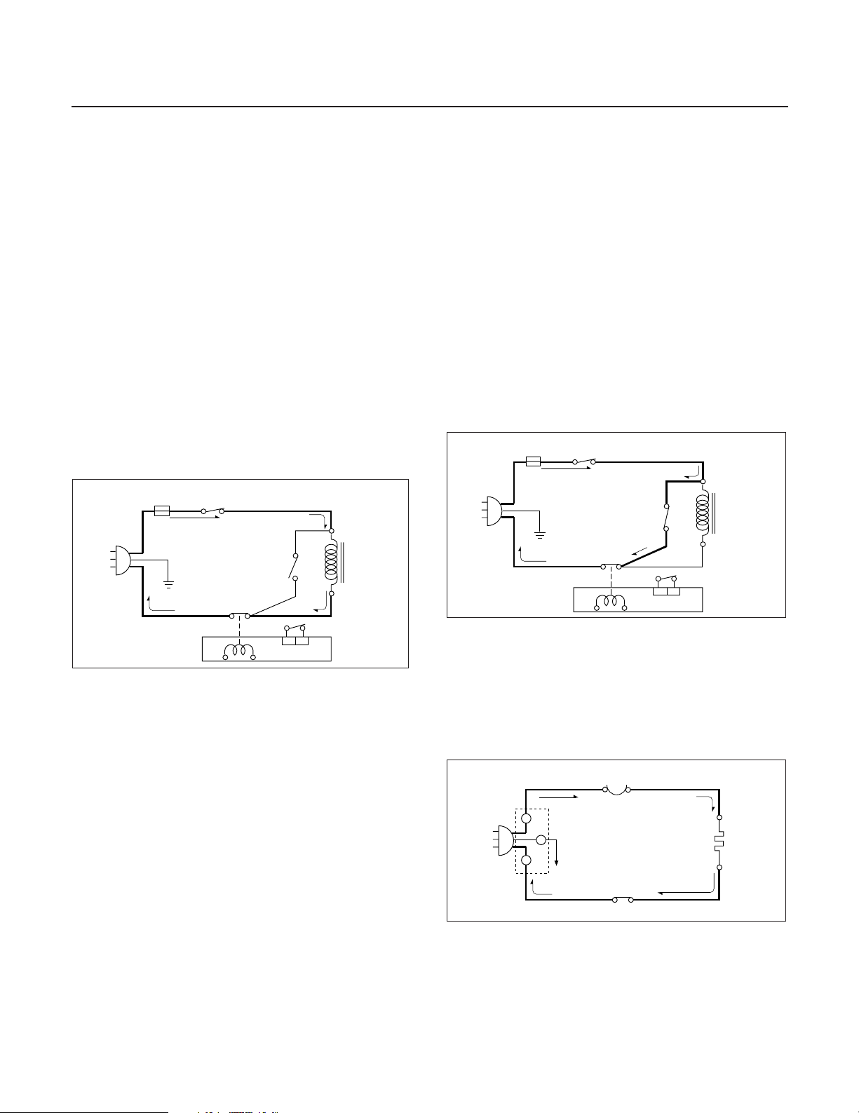
CIRCUIT DESCRIPTION
FUSE
H.V.
TRANS-
FORMER
RELAY 4
MICOM CONTROLLER
SECONDARY
SWITCH
PRIMARY
SWITCH
MONITOR
SWITCH
GENERAL DETAILS
• The low voltage transformer supplies the necessary
voltage to the micom controller when power cord is
plugged in.
• When the door is closed, the primary switch is ON, the
secondary switch is ON, and the monitor switch opens
(contact COM and NO).
WHEN SELECTING COOKING POWER
LEVEL AND TIME
• The micom controller memorizes the function you set.
• The time you set appears in the display window.
• Each indicator light turns on to indicate that the stage
has been set.
WHEN TOUCHING THE START BUTTON
• The coil of the relay is energized by the micom
controller.
• Power input is supplied to the high voltage transformer
through the fuse to the primary switch and relay 4.
• Turntable rotates.
power of oven as POWER LEVEL. (refer to page 1-1)
• One complete cycle of relay 4 is 32 seconds.
WHEN THE DOOR IS OPENED DURING
COOKING
• Both the primary switch and relay 4 are cut off primary
winding voltage of the high voltage transformer.
• ON-OFF of relay 4 is coupled electrically with opening
and closing of the secondary switch.
• When the door is opened, the secondary switch is
opened and when the door is closed, the secondary
switch is closed.
• The cooking time stops counting down.
• Relay stops functioning.
• As the door is opened, if the contact of primary switch
and relay 4 and/or secondary switch fails to open, the
fuse opens due to the large current surge caused by
the monitor switch activation, which in turn stops
magnetron oscillation.
FUSE
PRIMARY
SWITCH
MONITOR
SWITCH
H.V.
TRANS-
FORMER
• The fan motor rotates and cools the magnetron by
blowing the air (coming from the intake on the
back cover).
• The air is also directed into the oven to exhaust the
vapor in the oven through the upper plate.
• Cooking time starts counting down.
• 3.2 volts AC is generated from the filament winding of
the high voltage transformer. This 3.2 volts is applied to
the magnetron to heat the magnetron filament through
two noise-preventing choke coils.
• A high voltage of approximately 2100 volts AC is
generated in the secondary of the high voltage
transformer which is increased by the action of the high
voltage diode and charging of the high voltage
capacitor.
• The negative 4000 Volts DC is applied to the filament
of the magnetron.
WHEN THE OVEN IS SET AT ANY LEVEL
EXCEPT MAXIMUM.
• The micom controller controls the ON-OFF time of
relay 4 by the applied signal to vary the average output
RELAY 4
MICOM CONTROLLER
SECONDARY
SWITCH
WHEN TOUCHING THE START BUTTON
WITH THE HEATER COOKING
FUNCTION SELECTED
• The contacts of the primary switch and the secondary
switch close the circuit.
• A.C. voltage is applied to the heater through thermostat
as shown by the solid line.
THERMOSTAT
L
L
G -Y
N
E
N
RELAY 5,6,7
• Turntable rotates.
• The fan motor rotates.
• The air is also directed into the oven to exhaust the
vapor in the oven through the base plate and back
plate.
HEATER
4-4
SERVICE INFORMATION
TOOLS AND MEASURING INSTRUMENTS
NECESSARY TOOLS
Tools normally used for TV servicing are sufficient.
Standard tools are listed below.
• Diagonal pliers
• Long nose pliers
• Phillips screwdriver
• Flat blade screwdriver
• Wrench (size 5mm)
• Nutdriver (size 5mm)
• Adjustable wrench
• Soldering iron
• Solder
• Vinyl insulation tape
• Polishing cloth
MICROWAVE LEAKAGE TEST
CAUTIONS
• Be sure to check microwave leakage prior to
servicing the oven if the oven is operative prior to
servicing.
• The service personnel should inform the
manufacture importer, or assembler of any
certified oven unit found to have a microwave
emission level in excess of 5 mW/cm2and should
repair any unit found to have excessive emission levels
at no cost to the owner and should ascertain the cause
of the excessive leakage. The service personnel
should instruct the owner not to use the unit until the
oven has been brought into compliance.
• If the oven operates with the door open, the service
personnel should:
- Tell the user not to operate the oven.
- Contact the manufacturer.
• The service personnel should check all surface and
vent openings for microwave leakage.
• Check for microwave leakage after every servicing.
The power density of the microwave radiation leakage
emitted by the oven should not exceed 4 mW/cm2.
Always start measuring of an unknown field to assure
safety for operating personnel from radiation leakage.
NECESSARY MEASURING INSTRUMENTS
• TESTER(VOLTS-DC, AC., Ohmmeter)
• Microwave survey meter
- Holaday HI-1500
HI-1501
- Narda 8100
8200
• Inch scale
• 600 cc non conductive material beaker (glass or plastic),
inside diameter: approx. 8.5 cm(3
• Cylindrical and made of borosilicate glass vessel.
max. thickness: 3 mm
outside diameter: approx. 190mm
height: approx. 90mm
• Glass thermometer: 100°C or 212°F (1 deg scale)
1
/2 in.)
MEASURING MICROWAVE ENERGY
LEAKAGE
• Pour 275±15cc of 20±5°C(68±9°F) water in a beaker
which is graduated to 600 cc, and place the beaker
on the center of the turntable.
• Set the energy leakage monitor to 2450 MHz and
use it following the manufacturer's recommended
test procedure to assure correct result.
• When measuring the leakage, always use the 2-
inch (5cm) spacer supplied with the probe.
• Operate the oven at its maximum output.
• Measure the microwave radiation using and
electromagnetic radiation monitor by holding the
probe perpendicular to the surface being measured
Move probe along shaded area
Probe scanning speed
Less than 2.5 cm/sec
(1in/sec)
5-1
MEASUREMENT WITH OUTER CASE
REMOVED
• When you replace the magnetron, measure for
microwave energy leakage before the outer case is
installed and after all necessary components are
replaced or adjusted.
Special care should be taken in measuring the
following parts. (Circled area of below Fig.)
- Around the magnetron
- The waveguide
WARNING : AVOID CONTACTING ANY
HIGH VOLTAGE PARTS
NOTES WHEN MEASURING
• Do not exceed meter full scale deflection.
• The test probe must be removed no faster than
1 inch/sec (2.5 cm/sec) along the shaded area,
otherwise a false reading may result.
• The test probe must be held with the grip portion of the
handle.
A false reading may result if the operator's hand is
between the handle and the probe.
• When testing near a corner of the door, keep the probe
perpendicular to the surface making sure the probe
horizontally along the oven surface, this may possibly
cause probe damage.
RECORD KEEPING AND NOTIFICATION
AFTER MEASUREMENT
• After adjustment and repair of any microwave energy
interruption or microwave energy blocking device,
record the measured values for future reference. Also
enter the information on the service invoice.
• The microwave energy leakage should not be more
than 4 mW/cm.sq. after determining that all parts are in
good condition, functioning properly and genuine
replacement parts which are listed in this manual have
been used.
• At least once a year, have the electromagnetic energy
leakage monitor checked for calibration by its
manufacturer.
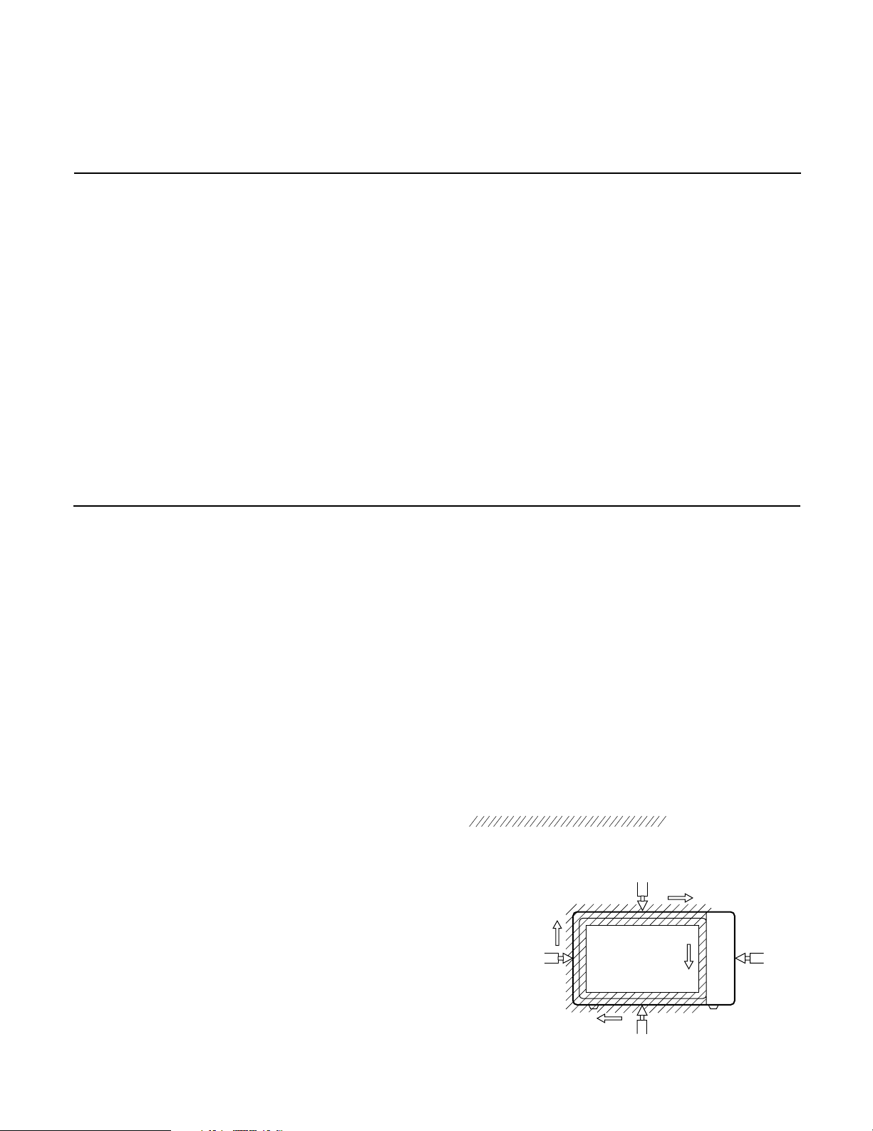
MEASUREMENT WITH A FULLY
ASSEMBLED OVEN
• After all components, including the outer case, are fully
assembled, measure for microwave energy leakage
around the door viewing window, the exhaust opening,
and air inlet openings.
• Microwave energy leakage must not exceed the values
prescribed below.
NOTE: Leakage with the outer case removed less than
5 mW/cm.sq. Leakage for a fully assembled
oven (Before the latch switch (primary) is
interrupted) with the door in a slightly opened
position-less than 2 mW/cm.sq.
5-2
 Loading...