

LG 37SL80UB Users manual

Order Number : GETEC-C1-09-138 FCC Class B Certification
Test Report Number : GETEC-E3-09-074 Page 1 / 1
APPENDIX G
: USER’S MANUAL
EUT Type: LCD TV/ Monitor
FCC ID.: BEJ37SL80UB

Please read this manual carefully before operating
your set and retain it for future reference.
The model and serial number of the TV is located
on the back and one side of the TV.
Record it below should you ever need service.
LCD TV
OWNER’S MANUAL
42LH90
47LH90
55LH90
P/NO : SAC33601906 (0906-REV03)
www.lgusa.com / www.lg.ca
This product qualifies for ENERGY STAR in the “factory
default (Home Use)” setting.
Changing the factory default settings or enabling other features may increase power consumption that could exceed the
limits necessary to qualify for ENERGY STAR.
Model:
Serial:
1-800-243-0000 USA, Consumer User
1-888-865-3026 USA, Commercial User
1-888-542-2623 CANADA
LG Customer Information Center
32SL80
37SL80
42SL80
47SL80
55SL80
2
WARNING / CAUTION
The lightning flash with arrowhead
symbol, within an equilateral triangle, is
intended to alert the user to the presence
of uninsulated “dangerous voltage” within the
product’s enclosure that may be of sufficient
magnitude to constitute a risk of electric shock to
persons.
The exclamation point within an equilateral
triangle is intended to alert the user to
the presence of important operating and
maintenance (servicing) instructions in the literature accompanying the appliance.
TO REDUCE THE RISK OF ELECTRIC SHOCK
DO NOT REMOVE COVER (OR BACK). NO
USER SERVICEABLE PARTS INSIDE. REFER TO
QUALIFIED SERVICE PERSONNEL.
WARNING/CAUTION
TO REDUCE THE RISK OF FIRE AND ELECTRIC
SHOCK, DO NOT EXPOSE THIS PRODUCT TO
RAIN OR MOISTURE.
NOTE TO CABLE/TV INSTALLER
This reminder is provided to call the CATV system
installer’s attention to Article 820-40 of the National
Electric Code (U.S.A.). The code provides guidelines for
proper grounding and, in particular, specifies that the
cable ground shall be connected to the grounding system
of the building, as close to the point of the cable entry
as practical.
WARNING / CAUTION
To prevent fire or shock hazards, do not expose
this product to rain or moisture.
FCC NOTICE
Class B digital device
This equipment has been tested and found to comply
with the limits for a Class B digital device, pursuant to
Part 15 of the FCC Rules. These limits are designed
to provide reasonable protection against harmful
interference in a residential installation. This equipment
generates, uses and can radiate radio frequency energy
and, if not installed and used in accordance with the
instructions, may cause harmful interference to radio
communications. However, there is no guarantee that
interference will not occur in a particular installation.
If this equipment does cause harmful interference to
radio or television reception, which can be determined
by turning the equipment off and on, the user is
encouraged to try to correct the interference by one
or more of the following measures:
- Reorient or relocate the receiving antenna.
- Increase the separation between the equipment and
receiver.
- Connect the equipment to an outlet on a circuit
different from that to which the receiver is connected.
- Consult the dealer or an experienced radio/TV
technician for help.
This device complies with part 15 of the FCC Rules.
Operation is subject to the following two conditions: (1) This device may not cause (harmful)
interference, and (2) this device must accept any
interference received, including interference that
may cause undesired operation (of the device).
Any changes or modifications not expressly approved
by the party responsible for compliance could void
the user’s authority to operate the equipment.
CAUTION
Do not attempt to modify this product in any way
without written authorization from LG Electronics.
Unauthorized modification could void the user’s
authority to operate this product
3
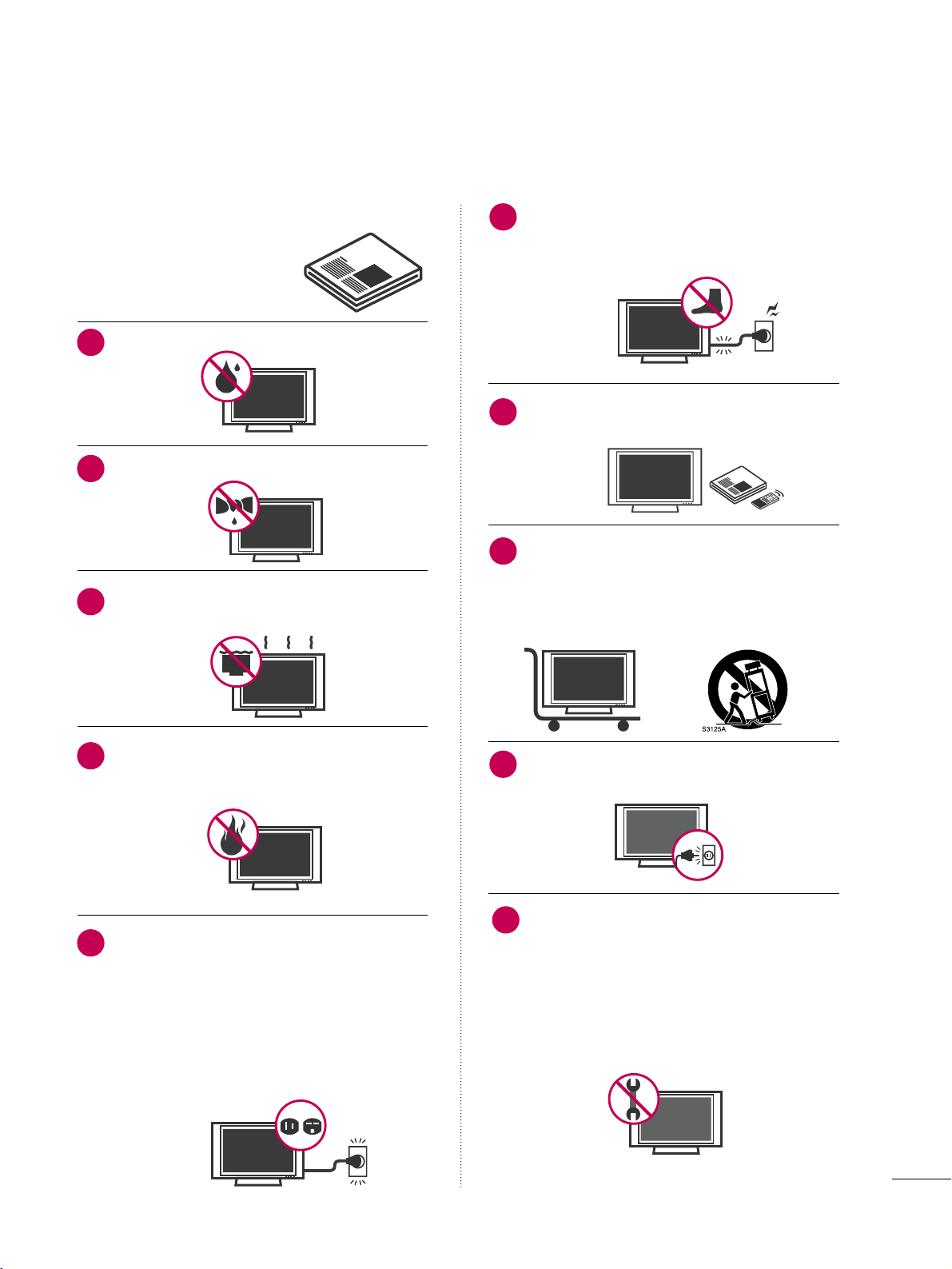
IMPORTANT SAFETY INSTRUCTIONS
SAFETY INSTRUCTIONS
Read these instructions.
Keep these instructions.
Heed all warnings.
Follow all instructions.
Do not use this apparatus near water.
Clean only with dry cloth.
Do not block any ventilation openings. Install in
accordance with the manufacturer’s instructions.
Do not install near any heat sources such as
radiators, heat registers, stoves, or other
apparatus (including amplifiers) that produce
heat.
Do not defeat the safety purpose of the polarized
or grounding-type plug. A polarized plug has
two blades with one wider than the other. A
grounding type plug has two blades and a
third grounding prong, The wide blade or the
third prong are provided for your safety. If the
provided plug does not fit into your outlet,
consult an electrician for replacement of the
obsolete outlet.
Protect the power cord from being walked on
or pinched particularly at plugs, convenience
receptacles, and the point where they exit from
the apparatus.
Only use attachments/accessories specified by
the manufacturer.
Use only with the cart, stand, tripod, bracket,
or table specified by the manufacturer, or sold
with the apparatus. When a cart is used, use
caution when moving the cart/apparatus combination to avoid injury from tip-over.
Unplug this apparatus during lighting storms
or when unused for long periods of time.
Refer all servicing to qualified service personnel.
Servicing is required when the apparatus has
been damaged in any way, such as powersupply cord or plug is damaged, liquid has
been spilled or objects have fallen into the
apparatus, the apparatus has been exposed to
rain or moisture, does not operate normally, or
has been dropped.
1
2
3
4
5
7
8
6
9
10
4
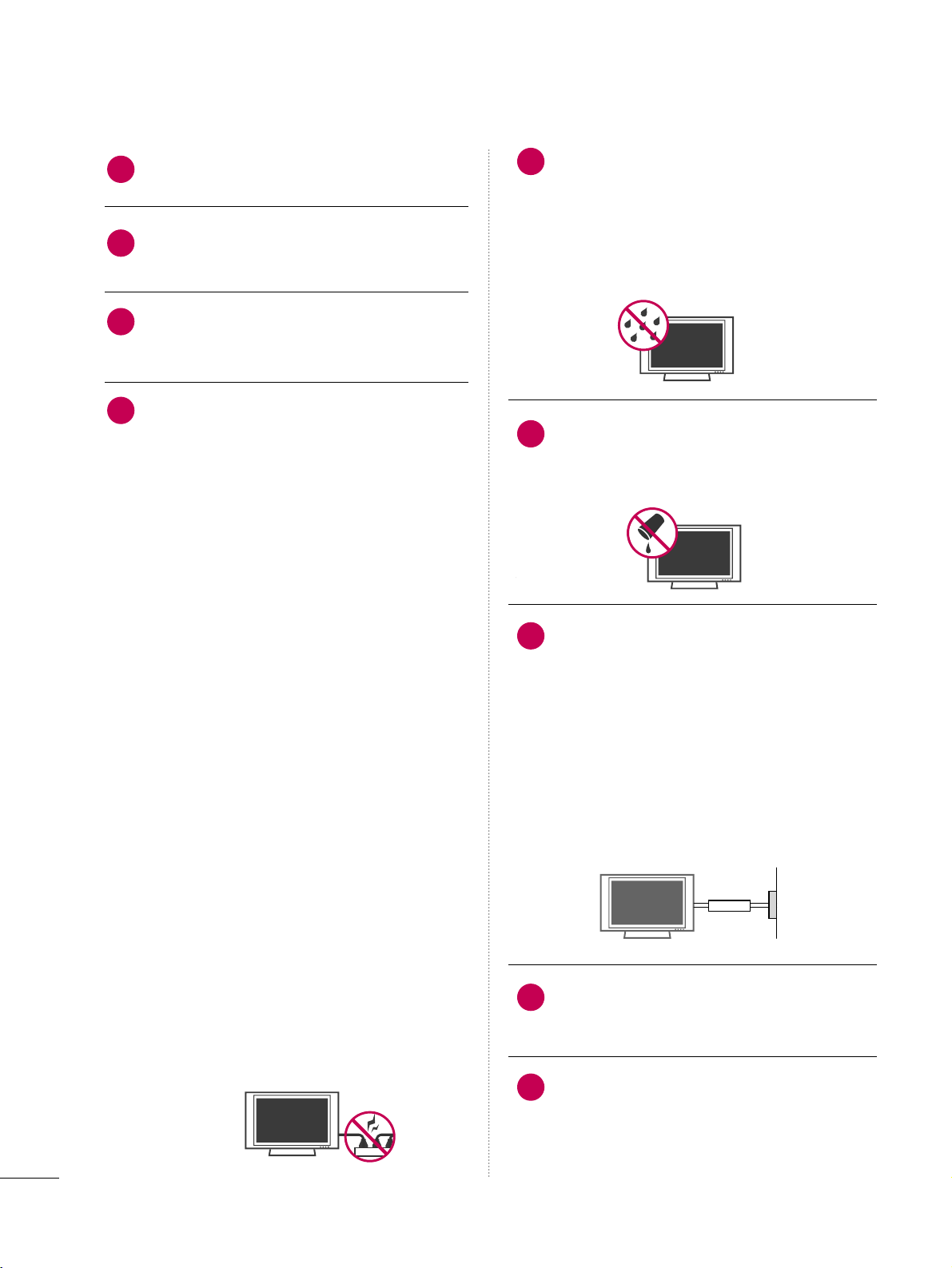
SAFETY INSTRUCTIONS
Never touch this apparatus or antenna during
a thunder or lighting storm.
When mounting a TV on the wall, make sure
not to install the TV by the hanging power and
signal cables on the back of the TV.
Do not allow an impact shock or any objects to
fall into the product, and do not drop onto the
screen with something.
CAUTION concerning the Power Cord:
It is recommend that appliances be placed
upon a dedicated circuit; that is, a single
outlet circuit which powers only that appliance
and has no additional outlets or branch
circuits. Check the specification page of this
owner's manual to be certain.
Do not connect too many appliances to the
same AC power outlet as this could result in
fire or electric shock.
Do not overload wall outlets. Overloaded wall
outlets, loose or damaged wall outlets, extension
cords, frayed power cords, or damaged or
cracked wire insulation are dangerous. Any of
these conditions could result in electric shock
or fire. Periodically examine the cord of your
appliance, and if its appearance indicates damage
or deterioration, unplug it, discontinue use of
the appliance, and have the cord replaced with
an exact replacement part by an authorized
servicer. Protect the power cord from physical
or mechanical abuse, such as being twisted,
kinked, pinched, closed in a door, or walked
upon. Pay particular attention to plugs, wall
outlets, and the point where the cord exits the
appliance.
Do not make the TV with the power cord
plugged in. Do not use a damaged or loose
power cord. Be sure do grasp the plug when
unplugging the power cord. Do not pull on the
power cord to unplug the TV.
WARNING - To reduce the risk of fire or electrical
shock, do not expose this product to rain,
moisture or other liquids. Do not touch the TV
with wet hands. Do not install this product
near flammable objects such as gasoline or
candles or expose the TV to direct air
conditioning.
Do not expose to dripping or splashing and do
not place objects filled with liquids, such as
vases, cups, etc. on or over the apparatus (e.g.
on shelves above the unit).
GGRROOUUNNDDIINN GG
Ensure that you connect the earth ground wire
to prevent possible electric shock (i.e. a TV
with a three-prong grounded AC plug must be
connected to a three-prong grounded AC outlet). If grounding methods are not possible,
have a qualified electrician install a separate
circuit breaker.
Do not try to ground the unit by connecting it
to telephone wires, lightening rods, or gas
pipes.
DDIISSCCOONNNNEECCTTIINNGG DDEEVVIICCEE FFRROOMM MMAAIINNSS
Mains plug is the disconnecting device. The
plug must remain readily operable.
As long as this unit is connected to the AC wall
outlet, it is not disconnected from the AC
power source even if you turn off this unit by
SWITCH.
12
11
14
13
16
17
18
19
Power
Supply
Short-circuit
Breaker
15

5
AANN TTEENNNN AA SS
OOuu ttddoooorr aannttee nnnn aa ggrr oouu nnddiinngg
If an outdoor antenna is installed, follow the
precautions below. An outdoor antenna system
should not be located in the vicinity of overhead power lines or other electric light or
power circuits, or where it can come in contact
with such power lines or circuits as death or
serious injury can occur.
Be sure the antenna system is grounded so as
to provide some protection against voltage
surges and built-up static charges.
Section 810 of the National Electrical Code
(NEC) in the U.S.A. provides information with
respect to proper grounding of the mast and
supporting structure, grounding of the lead-in
wire to an antenna discharge unit, size of
grounding conductors, location of antenna discharge unit, connection to grounding electrodes and requirements for the grounding
electrode.
AAnntteennnnaa ggrroouunnddiinngg aaccccoorrddiinngg ttoo tthhee
NNaattiioonnaall EElleeccttrriiccaall CCooddee,, AANNSSII//NNFFPPAA 7700
CC lleeaanniinngg
When cleaning, unplug the power cord and
scrub gently with a soft cloth to prevent
scratching. Do not spray water or other liquids
directly on the TV as electric shock may occur.
Do not clean with chemicals such as alcohol,
thinners or benzene.
MMoovviinn gg
Make sure the product is turned off,
unplugged and all cables have been removed. It
may take 2 or more people to carry larger TVs.
Do not press against or put stress on the front
panel of the TV.
VVeenn ttii llaatt iioonn
Install your TV where there is proper ventila-
tion. Do not install in a confined space such as
a bookcase. Do not cover the product with
cloth or other materials (e.g.) plastic while
plugged in. Do not install in excessively dusty
places.
If you smell smoke or other odors coming from
the TV or hear strange sounds, unplug the power
cord contact an authorized service center.
Do not press strongly upon the panel with
hand or sharp object such as nail, pencil or
pen, or make a scratch on it.
Keep the product away from direct sunlight.
FFoo rr LLCCDD TTVV
If the TV feels cold to the touch, there may be
a small “flicker” when it is turned on. This is
normal, there is nothing wrong with TV.
Some minute dot defects may be visible on the
screen, appearing as tiny red, green, or blue
spots. However, they have no adverse effect on
the monitor's performance.
Avoid touching the LCD screen or holding your
finger(s) against it for long periods of time.
Doing so may produce some temporary distortion effects on the screen.
20
23
24
25
26
27
21
22
Antenna Lead in Wire
Antenna Discharge Unit
(NEC Section 810-20)
Grounding Conductor
(NEC Section 810-21)
Ground Clamps
Power Service Grounding
Electrode System (NEC
Art 250, Part H)
Ground Clamp
Electric Service
Equipment
NEC: National Electrical Code
8
FEATURE OF THIS TV
■
When a fixed image (e.g. logos, screen menus, video game, and computer display) is displayed on the TV
for an extended period, it can become permanently imprinted on the screen. This phenomenon is known
as “image burn” or “burn-in.” Image burn is not covered under the manufacturer’s warranty.
■
In order to prevent image burn, avoid displaying a fixed image on your TV screen for a prolonged period
(2 or more hours for LCD, 1 or more hours for Plasma TV).
■
Image burn can also occur on the letterboxed
areas of your TV if you use the 4:3 aspect
ratio setting for an extended period.
IMPORTANT INFORMATION TO PREVENT “IMAGE BURN
/ BURN-IN” ON YOUR TV SCREEN
AV Mode is three preset picture and audio settings. It
allows the viewer to quickly switch between common settings. It includes Cinema, Sports, and Game Modes.
Displays HDTV programs in full 1920 x 1080p resolution for a more detailed picture.
Automatically enhances and amplifies the sound of
human voice frequency range to help keep dialogue
audible when background noise swells.
A unique invisible speaker system tuned by renowned
audio expert, Mr. Mark Levinson. Speakers are embedded in strategic spots behind the front cabinet and
use minute vibrations to turn the entire front bezel
into the speaker system. The result s a clean, polished
look, and enhanced audio by increasing the “sweet
spot”, giving a wider and richer sound field.
HDMI, the HDMI logo and High-Definition
Multimedia Interface are trademarks or registered
trademarks of HDMI Licensing LLC."
is a trademark of SRS Labs, Inc.
TruSurround XT technology is incorporated under
license from SRS Labs, Inc.
Manufactured under license from Dolby Laboratories.
“
Dolby
“and the double-D symbol are trademarks of
Dolby Laboratories.
This TV contains the detailed calibrations necessary
for professional certification by the Imaging Science
Foundation. The resulting ISF “day” and “night” modes
will then be accessible by the user to experience the
best their LG HDTV has to offer.
Sophisticated and detailed calibrations can be made
through the ISFccc mode.
Detailed calibration requires a licensed technician.
Please contact your local dealer to inquire about an
ISF certified technician.
High-definition television. High-resolution digital
television broadcast and playback system composed
of roughly a million or more pixels, 16:9 aspect-ratio
screens, and AC3 digital audio. A subset of digital
television, HDTV formats include 1080i and 720p
resolutions.
TruMotion 240Hz displays 240 scenes per second by
combining advanced 120Hz technology with scanning
back light. This technology is verified from Intertek &
TüV Rheinland.
“DivX Certified to play DivX video up to HD 1080p,
including premium content”
ABOUT DIVX VIDEO: DivX® is a digital video format
created by DivX,Inc. This is an official DivX Certified
device that plays DivX video. Visit www.divx.com for
more information and software tools to convert your
files into DivX video.
ABOUT DIVX VIDEO-ON-DEMAND: This DivX
Certified® device must be registered in order to play
DivX Video-on-Demand (VOD) content. To generate
the registration code, locate the DivX VOD section in
the device setup menu. Go to vod.divx.com with this
code to complete the registration process and learn
more about DivX VOD.
THX (Thomlinson Holman’s Experiment) is the audio
and video certification standard of THX established
by George Lucas, who directed the movie Star Wars,
and Thomlinson.
This is the product to be certified in THX display area
and guarantees screen quality that exceeds the display
standard specification in both hardware and software.
PREPARATION
9
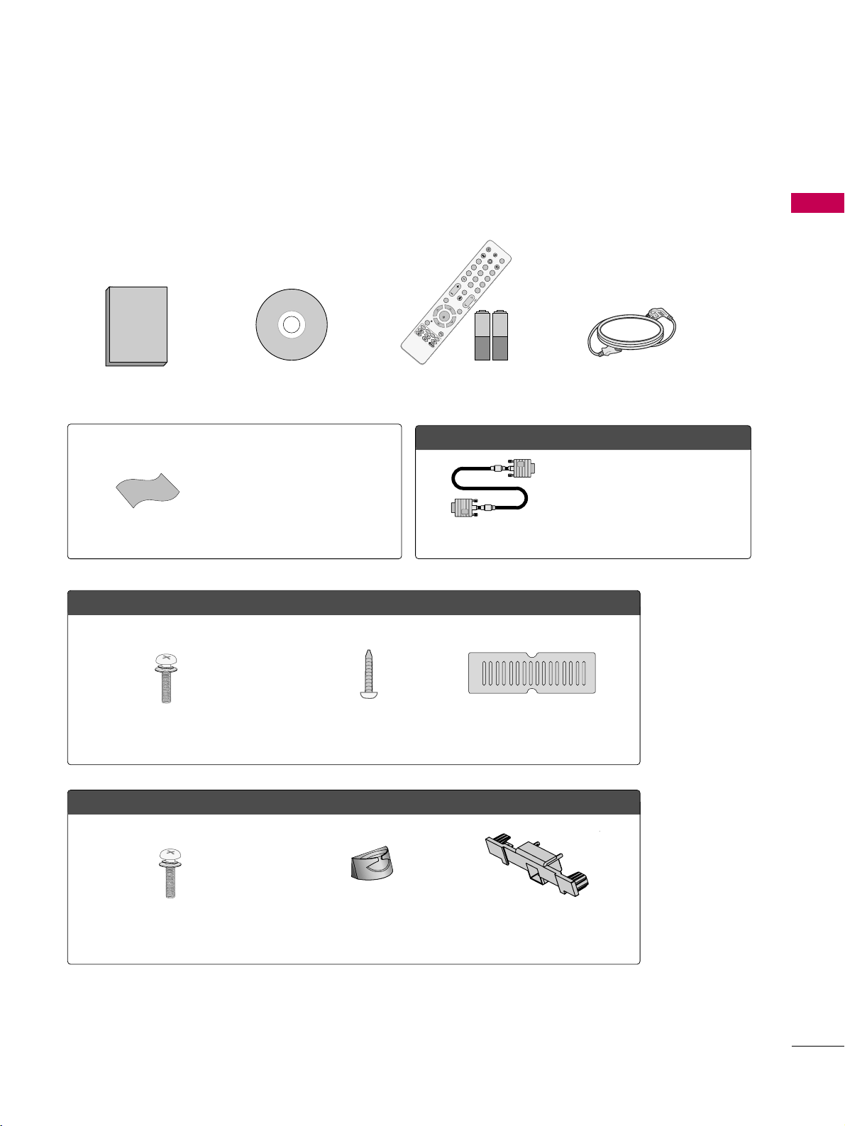
ACCESSORIES
PREPARATION
Ensure that the following accessories are included with your TV. If an accessory is missing, please contact the
dealer where you purchased the TV.
The accessories included may differ from the images below.
Owner’s Manual Power Cord
CD Manual
OOppttiioonn EExxttrraass
* Wipe spots on the exterior only with
the polishing cloth.
* Do not wipe roughly. Excessive pres-
sure may cause scratches or discoloration.
Polishing Cloth
Not included with all models
D-sub 15 pin Cable
When using the VGA (D-sub 15 pin
cable) PC connection, the user
must use shielded signal interface
cables with ferrite cores to maintain
standards compliance.
OOnnllyy 4422//4477//5555LLHH9900
OOnnllyy 3322//3377//4422//4477//5555SSLL8800
Bolts for stand assembly
(Refer to P.13)
Cable Management Clip
(Refer to P.15)
Protection Cover
(Refer to P.13)
x 8
1.5V 1.5V
Remote Control,
Batteries
F
A
V
M
U
T
E
Q
.
M
E
NU
M
E
NU
AV MODE
RETURN
VOL
C
H
123
456
78
0
9
FLASHBK
P
A
G
E
INPU
T
INFO
LIST
ENT
E
R
POWER
TV
ENERGY SAVING
ON/OF
F
MARK
Protection Cover
Screws for stand assembly
(Refer to P.12)
Screw for stand fixing
(Refer to P.17)
x 4
(For 42/47LH90)
(Except 55SL80)
(For 42LH90)

PREPARATION
10
FRONT PANEL INFORMATION
PREPARATION
■
Image shown may differ from your TV.
CHANNEL ( , )
Buttons
VOLUME (+, -)
Buttons
ENTER Button
MENU Button
INPUT Button
POWER Button
AC power control switch
SPEAKER
Power/Standby Indicator
Illuminates red in standby mode.
Illuminates white when the TV is switched on.
(Can be adjusted using the
PP ooww ee rr IInnddii ccaattoorr
in
the OPTION menu.
GG
pp..77 88
)
Remote Control Sensor,
Power/Standby Indicator
Illuminates red in standby
mode.
Illuminates blue when the
TV is switched on (Can be
adjusted using the
PPoo ww eerr
II nn ddiiccaattoorr
in the OPTION
menu.
GG
pp .. 7788
).
Remote Control Sensor,
Intelligent Sensor
Adjusts picture according to
the surrounding conditions
42/47/55LH90
32/37/42/47/55SL80
INPUT
Button
POWER
Button
MENU
Button
ENTER
Button
VOLUME
(-, +)
Buttons
CHANNEL
( , )
Buttons
Main power switch
(For 37/42/47/55SL80)
OFF ON
Main power switch
(For 32SL80)
ON OFF
CH
VOL
ENTER
MENU
INPUT
CH
VOL
ENTER
MENU
INPUT
PREPARATION
11
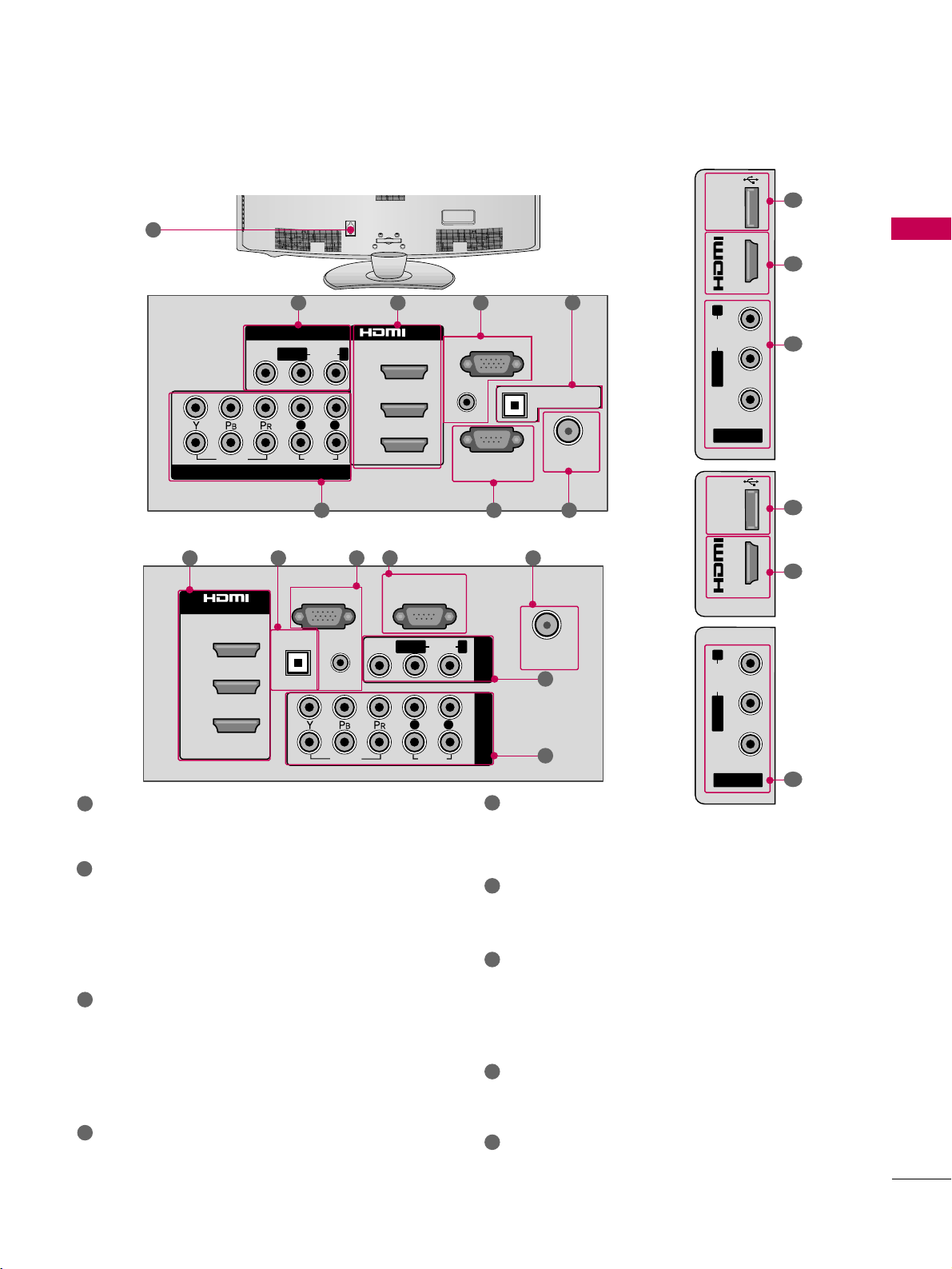
BACK PANEL INFORMATION
AV (Audio/Video) IN
Analog composite connection. Supports standard
definition video only (480i).
HDMI/DVI IN, HDMI IN
Digital Connection.
Supports HD video and Digital audio. Doesn’t
support 480i.
Accepts DVI video using an adapter or HDMI to
DVI cable (not included).
RGB IN (PC)
Analog PC Connection. Uses a D-sub 15 pin cable
(VGA cable).
AUDIO IN (RGB/DVI)
1/8" (0.32 cm) headphone jack for analog PC
audio input.
OPTICAL DIGITAL AUDIO OUT
Digital optical audio output for use with amps and
home theater systems.
Note: In standby mode, this port doesn’t work.
ANTENNA/CABLE IN
Connect over-the air signals to this jack.
Connect cable signals to this jack.
RS-232C IN (CONTROL & SERVICE) PORT
Used by third party devices.
This port is used for Service or Hotel mode.
COMPONENT IN
Analog Connection.
Supports HD.
Uses a red, green, and blue cable for video & red
and white for audio.
USB IN
Used for viewing photos/movies and listening to
MP3s.
Power Cord Socket
For operation with AC power.
Caution: Never attempt to operate the TV on DC
power.
1
2
3
4
8
9
7
6
5
■
Image shown may differ from your TV.
( )
( )
R
1 2
6 57
9
1
8
2
4
3
42/47/55LH90
USB IN
IN 4
AV IN 2
L/ MONO
R
AUDIO
VIDEO
VIDEO
AUDIO
L R
(
CONTROL&SERVICE)
RS-232C IN
AUDIO IN
(RGB/DVI)
DIGITAL
AUDIO OUT
OPTICAL
ANTENNA/
CABLE IN
RGB IN (PC)
COMPONENT IN
2
3
1
1
2
MONO
( )
AUDIOVIDEO
/DVI IN
LR
R
AV IN 1
2 4 3 6 5
1
7
1
8
2
32/37/42/47/55SL82
AV IN 1
(
)
MONO
AUDIOVIDEO
LR
2
L R
1
VIDEO
COMPONENT IN
AUDIO
3
2
1
/DVI IN
RGB IN (PC)
AUDIO IN
(RGB/DVI)
RS-232C IN
(
CONTROL&SERVICE)
OPTICAL DIGITAL
AUDIO OUT
ANTENNA/
CABLE IN
USB IN
IN 4
R
AUDIO
L/ MONO
VIDEO
AV IN 2
PREPARATION
14
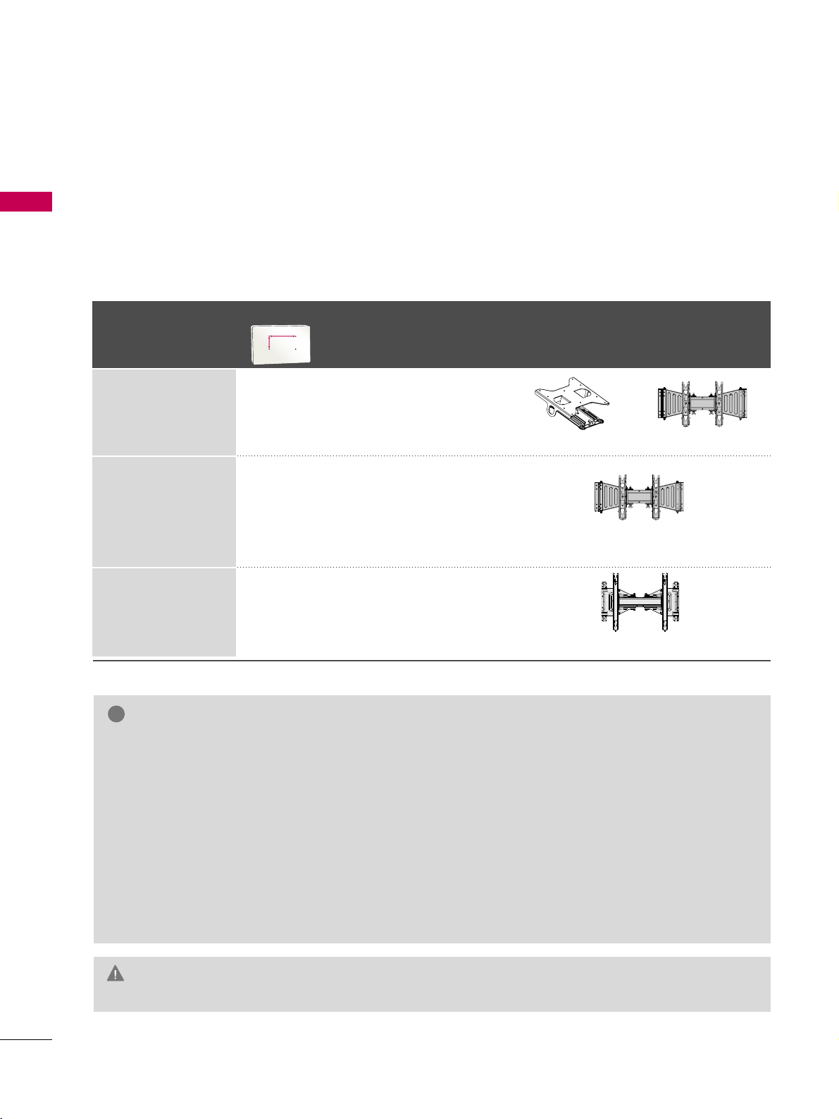
VESA WALL MOUNTING
PREPARATION
Install your wall mount on a solid wall perpendicular to the floor. When attaching to other building materials, please
contact your nearest installer.
If installed on a ceiling or slanted wall, it may fall and result in severe personal injury.
We recommend that you use an LG brand wall mount when mounting the TV to a wall.
LG recommends that wall mounting be performed by a qualified professional installer.
GG
Do not install your wall mount kit while your TV is turned on. It may result in personal
injury due to electric shock.
CAUTION
GG
Screw length needed depends on the wall mount
used. For further information, refer to the instructions included with the mount.
GG
Standard dimensions for wall mount kits are shown
in the table.
GG
When purchasing our wall mount kit, a detailed
installation manual and all parts necessary for
assembly are provided.
GG
Do not use screws longer then the standard dimension, as they may cause damage to the inside to
the TV.
GG
For wall mounts that do not comply with the VESA
standard screw specifications, the length of the
screws may differ depending on their specifications.
GG
Do not use screws that do not comply with the
VESA standard screw specifications.
Do not use fasten the screws too strongly, this may
damage the TV or cause the TV to a fall, leading to
personal injury. LG is not liable for these kinds of
accidents.
GG
LG is not liable for TV damage or personal injury
when a non-VESA or non specified wall mount is
used or the consumer fails to follow the TV installation instructions.
NOTE
!
Model
VESA (A *B)
Standard Screw Quantity
Wall Mounting Bracket
(sold separately)
32SL80
55 LH 90 ,
55SL80
42LH 90,
47LH90,
37SL80,
42SL80,
47SL80,
200* 10 0 M 4 4
200* 200 M6 4
400* 400 M6 4
AW-55LH40M
AA
BB
AW-47LG30M
RW230 AW-47LG30M
PREPARATION
16
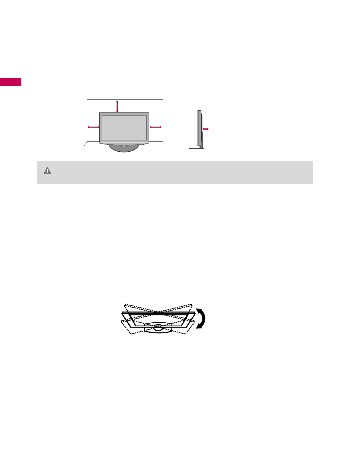
DESKTOP PEDESTAL INSTALLATION
PREPARATION
For proper ventilation, allow a clearance of 4 inches on all four sides from the wall.
■
Image shown may differ from your TV.
4 inches
GG
Ensure adequate ventilation by following the clearance recommendations.
GG
Do not mount near or above any type of heat source.
CAUTION
4 inches
4 inches
4 inches
SWIVEL STAND
After installing the TV, you can adjust the TV set manually to the left or right direction by 20 degrees to suit
your viewing position.
PREPARATION
17
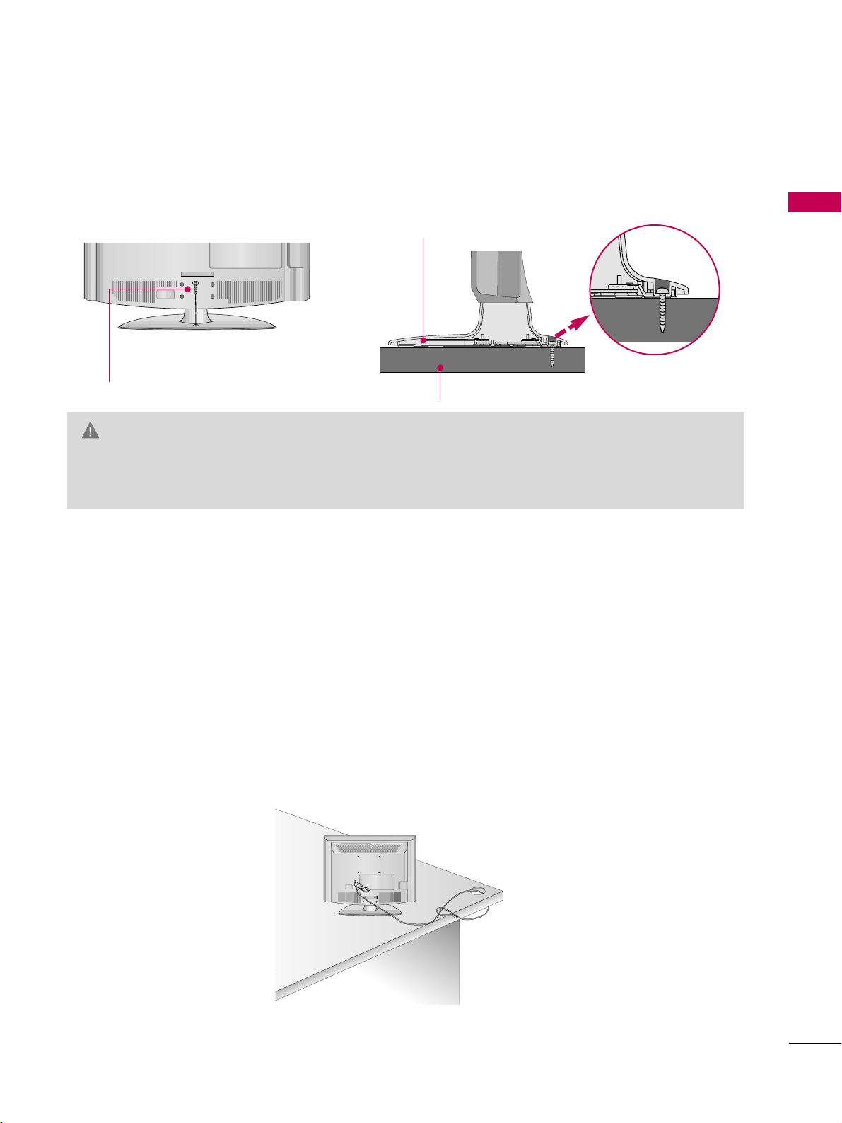
ATTACHING THE TV TO A DESK (For 42LH90)
KENSINGTON SECURITY SYSTEM
The TV must be attached to a desk so it cannot be pulled in a forward/backward direction, potentially causing
injury or damaging the product.
GG
To prevent TV from falling over, the TV should be securely attached to the floor/wall per installation
instructions. Tipping, shaking, or rocking the machine may cause injury.
WARNING
1-Screw
(provided as parts of the product)
Desk
Stand
■
Image shown may differ from your TV.
■
This feature is not available for all models.
- The TV is equipped with a Kensington Security System connector on the back panel. Connect the Kensington
Security System cable as shown below.
- For the detailed installation and use of the Kensington Security System, refer to the user’s guide provided with
the Kensington Security System.
For further information, contact
hh ttttpp:: ////wwwwww..kk ee nnssii nnggttoo nn.. ccoo mm
, the internet homepage of the Kensington
company. Kensington sells security systems for expensive electronic equipment such as notebook PCs and LCD
projectors.
NOTE: The Kensington Security System is an optional accessory.

PREPARATION
19
ANTENNA OR CABLE CONNECTION
■
To prevent damage do not connect to the power outlet until all connections are made between the devices.
■
Image shown may differ from your TV.
1. Antenna (Analog or Digital)
Wall Antenna Socket or Outdoor Antenna without a Cable Box
Connections.
For optimum picture quality, adjust antenna direction if needed.
2. Cable
Wall
Antenna
Socket
Outdoor
Antenna
(VHF, UHF)
Cable TV
Wall Jack
Multi-family Dwellings/Apartments
(Connect to wall antenna socket)
RF Coaxial Wire (75 ohm)
RF Coaxial Wire (75 ohm)
Single-family Dwellings /Houses
(Connect to wall jack for outdoor antenna)
Be careful not to bend the copper wire
when connecting the antenna.
Copper Wire
■
To improve the picture quality in a poor signal area, please purchase a signal amplifier and install properly.
■
If the antenna needs to be split for two TV’s, install a 2-Way Signal Splitter.
■
If the antenna is not installed properly, contact your dealer for assistance.
ANTENNA/
CABLE IN
R
ANTENNA/
CABLE IN
R
EXTERNAL EQUIPMENT SETUP
20
EXTERNAL EQUIPMENT SETUP
HD RECEIVER SETUP
This TV can receive digital over-the-air/digital cable signals without an external digital set-top box. However, if
you do receive digital signals from a digital set-top box or other digital external device.
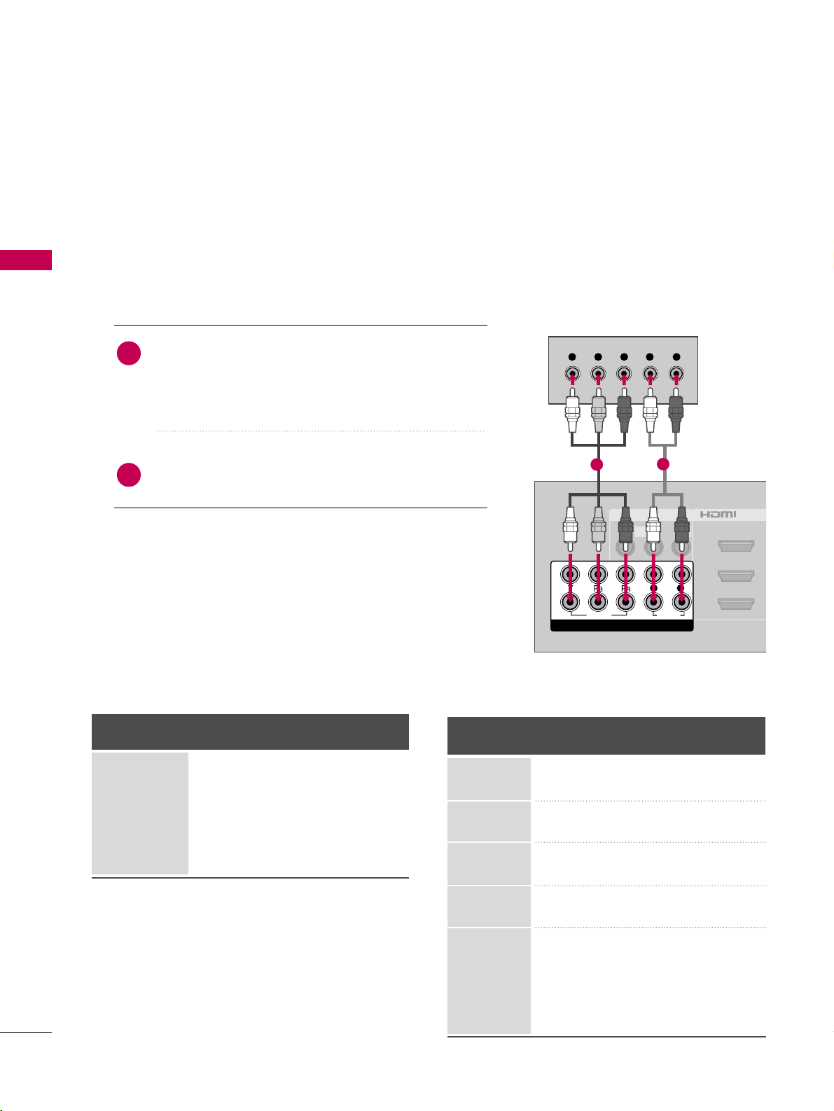
Component Connection
1. How to connect
Connect the video outputs (Y, P
B, PR
)
of the digital set-
top box to the
CC OO MMPP OO NNEENNTT IINN VVIIDDEEOO 11
or
22
jacks on the TV. Match the jack colors (Y = green, P
B =
blue, and P
R = red).
Connect the audio output of the digital set-top box to
the
CCOOMMPPOONNEENNTT IINN AAUUDDIIOO 11
or
22
jacks on the TV.
2
1
2. How to use
■
Turn on the digital set-top box.
(
Refer to the owner’s manual for the digital set-top box operation.
)
■
Select the
CC oommpp oonn ee nntt 11
or
22
input source on the TV
using the
IINNPP UUTT
button on the remote control.
■
To prevent the equipment damage, never plug in any power cords until you have finished connecting all equipment.
■
Image shown may differ from your TV.
Y, CB/PB, CR/PR
Supported Resolutions
Horizontal Vertical
Frequency(KHz)Frequency(Hz
)
15.73 59.94
15.73 60.00
31.47 59.94
31.50 60.00
44.96 59.94
45.00 60.00
33.72 59.94
33.75 60.00
26.97 23.976
27.00 24.00
33.71 29.97
33.75 30.00
67.432 59.94
67.50 60.00
Resolution
720x480i
720x480p
1280x720p
1920x1080i
1920x1080p
Signal
480i
480p
720p
10 8 0 i
10 8 0 p
Component
Yes
Yes
Yes
Yes
Yes
HDMI
No
Yes
Yes
Yes
Yes
AV IN 1
2
3
1
MONO
( )
AUDIOVIDEO L R
/DVI IN
VIDEO
AUDIO
L R
COMPONENT IN
2
1
Y L RPB PR
1
2
EXTERNAL EQUIPMENT SETUP
21
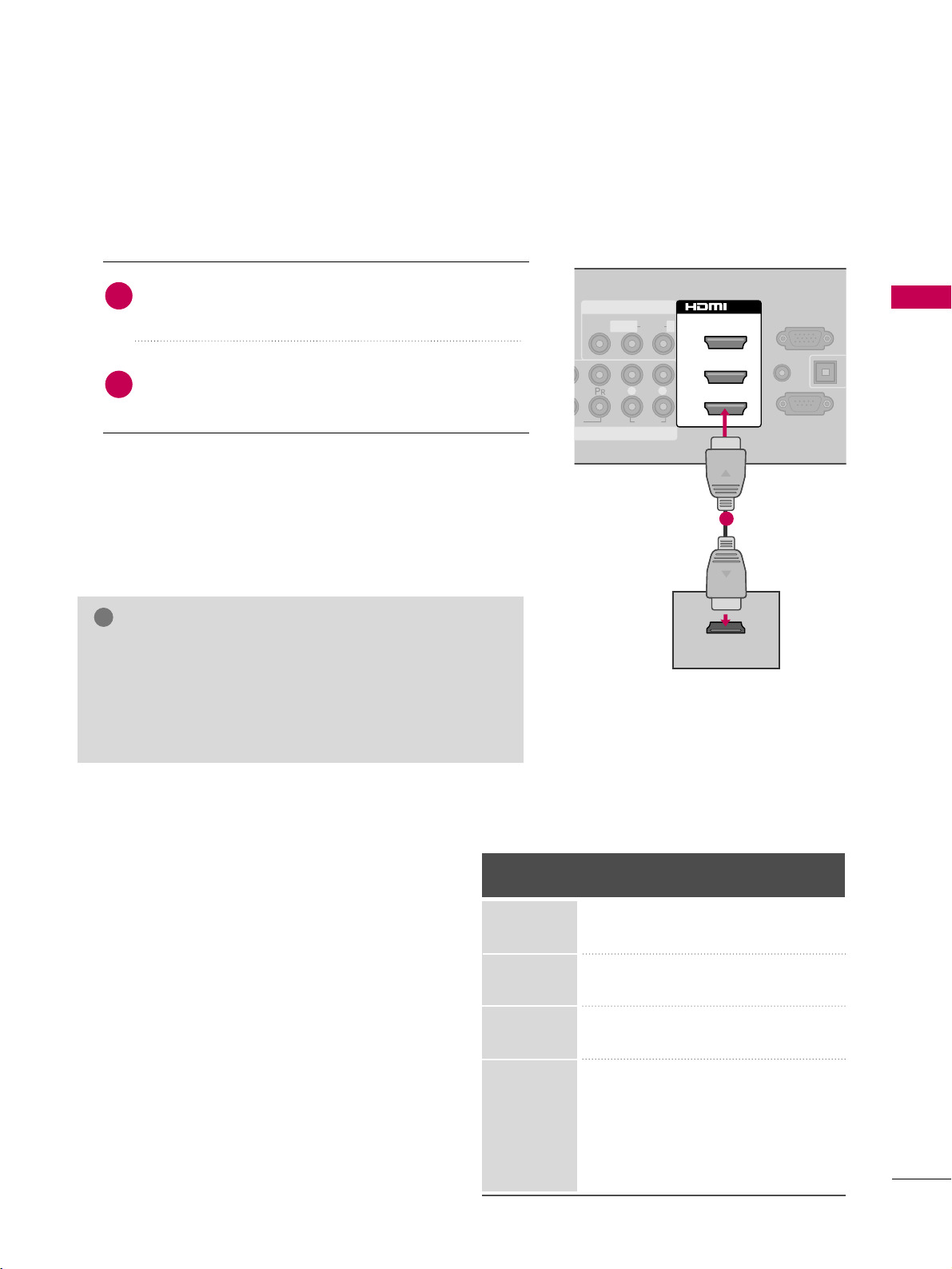
HDMI Connection
Connect the digital set-top box to
HHDDMM II //DDVVII IINN 11
,
22, 33
, or
44
jack on the TV.
No separate audio connection is necessary.
HDMI supports both audio and video.
1. How to connect
2. How to use
■
Turn on the digital set-top box.
(
Refer to the owner’s manual for the digital set-top box.
)
■
Select the
HHDDMMII11, HHDDMMII22, HHDDMMII33
, or
HHDDMMII44
input
source on the TV using the
IINNPPUUTT
button on the remote
control.
2
1
HDMI-DTV
Horizontal Vertical
Frequency(KHz)Frequency(Hz
)
31.47 59.94
31.50 60.00
44.96 59.94
45.00 60.00
33.72 59.94
33.75 60.00
26.97 23.976
27.00 24.00
33.71 29.97
33.75 30.00
67. 432 59 .94
67.50 60.00
Resolution
720x480p
1280x720p
1920x1080i
1920x1080p
( )
AUDIO
L R
RS-232C IN
(
CONTROL&SERVICE)
AUDIO IN
(RGB/DVI)
O
A
C
RGB IN (PC)
AV IN 1
1
MONO
( )
AUDIOVIDEO L R
2
3
1
/DVI IN
HDMI OUTPUT
1
GG
Check HDMI cable over version 1.3.
If the HDMI cables don’t support HDMI version 1.3, it can
cause flickers or no screen display. In this case use the latest cables that support HDMI version 1.3.
GG
HDMI mode supports PCM, Dolby Digital audio format.
NOTE
!

EXTERNAL EQUIPMENT SETUP
22
EXTERNAL EQUIPMENT SETUP
DVI to HDMI Connection
( )
( )
AUDIO
L R
RS-232C IN
(
CONTROL&SERVICE)
OPTICAL DIG
AUDIO OU
ANTENNA
CABLE IN
RGB IN (PC)
AV IN 1
1
MONO
( )
AUDIOLR
2
3
1
/DVI IN
AUDIO IN
(RGB/DVI)
L R
DVI OUTPUT
AUDIO
1
2
GG
A DVI to HDMI cable or adapter is required for this connection. DVI doesn't support audio, so a separate audio
connection is necessary.
NOTE
!
Connect the DVI output of the digital set-top box to
the
HHDDMMII //DDVVII II NN 11, 22
, or 33jack on the TV.
Connect the digital set-top box audio output to the
AAUUDDIIOO II NN ((RRGGBB// DD VV II
))
jack on the TV.
1. How to connect
2. How to use
■
Turn on the digital set-top box.
(
Refer to the owner’s manual for the digital set-top box.
)
■
Select the
HHDDMMII11, HHDDMMII22
, or
HHDDMMII33
input source on the
TV using the
IINNPPUUTT
button on the remote control.
2
1
EXTERNAL EQUIPMENT SETUP
23
DVD SETUP
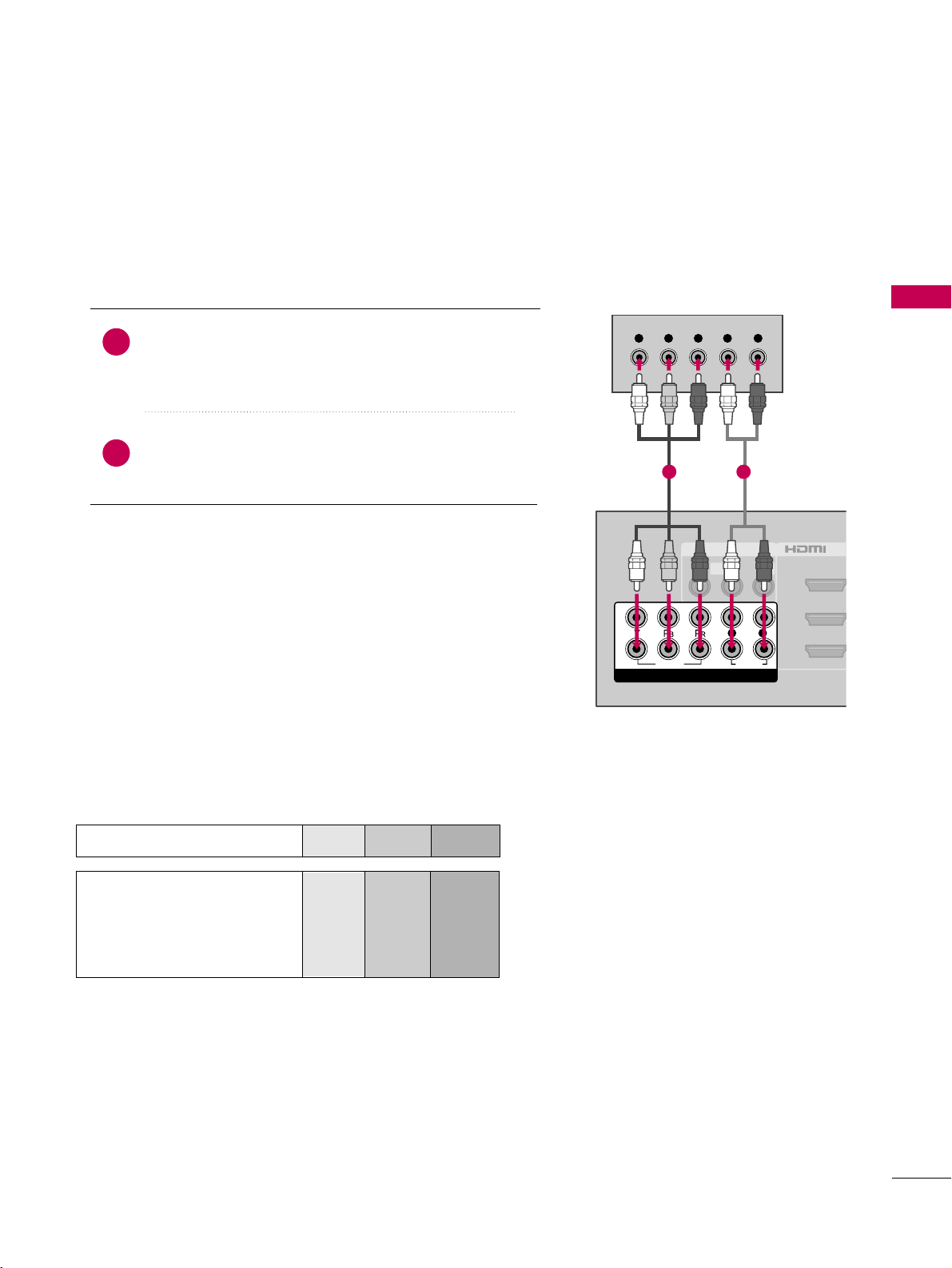
Component Connection
Component Input ports
To get better picture quality, connect a DVD player to the
component input ports as shown below.
Component ports on the TV
YPB PR
Video output ports
on DVD player
Y
Y
Y
Y
PB
B-Y
Cb
Pb
P
R
R-Y
Cr
Pr
Connect the video outputs (Y, PB
, PR
)
of the DVD to the
CC OO MMPP OO NNEENNTT IINN VVIIDDEEOO 11
or
22
jacks on the TV.
Match the jack colors (Y = green, P
B = blue, and PR = red
)
.
Connect the audio outputs of the DVD to the
CCOOMMPPOONNEENNTT IINN AAUUDDIIOO 11
or 22jacks on the TV.
1. How to connect
2. How to use
■
Turn on the DVD player, insert a DVD.
■
Select the
CC oommpp oonn ee nntt 11
or 22input source on the TV
using the
IINNPP UUTT
button on the remote control.
■
Refer to the DVD player's manual for operating instructions.
2
1
AV IN 1
2
3
1
MONO
( )
AUDIOVIDEO L R
/DVI
VIDEO
AUDIO
L R
COMPONENT IN
2
1
Y L RPB PR
1 2
 Loading...