

LG 32LP1R Series, 37LP1R Series, 42LP1R Series Owner's Manual
LCD TV
Please read Information Manual included together
before reading this manual and operating your set.
Retain it for future reference.
Record model number and serial number of the set.
See the label attached on the back cover and quote
this information to your dealer when you require service.
P/NO : 3828TUL313C(0508-REV01)
Printed in Korea
OWNER’S MANUAL
MODEL: 32LP1R**37LP1R
**
42LP1R
**

2
Owner’s Manual
1.5V
1.5V
Power Cord
Q.VIEW
1 2 3
4 5 6
8
0
9
S
M
S
L
E
E
P
I/II
ARC
O
K
OD
E
M
H
O
LD
X
P
I
P
P
R
-
P
IP P
R
+
S
W
A
P
PIP
INPU
T
VOL
PR
M
U
T
E
LIST
EXIT
T
V
F
A
V
O
U
R
IT
E
Q.VIEW
P
O
W
ER
1 2 3
4 5 6
78
0
9
A
UDIO
T
E
X
T
P
IP
CABLE
Z
O
O
M
-
ZOOM
+
P
S
M
SSM
S
T
B
S
L
E
E
P
I/II
M
EN
U
ARC
V
C
R
D
V
D
M
O
D
E
O
K
PO
SITIO
N
TIM
E
REV
E
AL
?
MO
D
E
M
MIX
SIZE
H
O
LD
IND
E
X
i
IN
P
U
T
TV
P
I
P
P
R
-
PIP PR+
S
W
A
P
PIP IN
P
UT
VOL
PR
M
U
T
E
LIST
EXIT
Remote Control / Batteries
Ensure that the following accessories are included with your TV. If any accessory is missing, please contact the
dealer from where you purchased the product.
Accessories
DVI-D cable (PC)
DVI to D-Sub cable (PC)
Audio cable (PC)
Twister Holder
Polishing Cloth
Polish the screen with the cloth.
3
ENGLISH
Contents
Contents
Introduction
Operation
2 Accessories
5 Controls
6 Connection Options
7 Remote Control Key Functions
9 Swivel stand (option)
Setting up
TV stations
Basic operation
Installation
10 Basic Connection
11 External Equipment Connections
11 Antenna Connection
12 VCR Setup
14 DVD Setup
16 STB ( Set-Top Box) Setup
17 Cable TV Setup
18 External AV Source Setup
18 Headphone Socket
19 PC Setup
20 Supported display resolution
20 Power Cord Connection
21 Turning On/Off the TV
21 Volume Adjustment
21 Programme selection
21
On screen language selection
22 How to adjust the OSD screen
23 Auto programme tuning
24 Manual programme tuning
25 Fine tuning
26 Assigning a station name
27 Programme edit
28
Favourite programme
28
Calling the programme table
29
PSM (Picture Status Memory)
29 CSM (Colour Status Memory)
30 Function
30 ACM (Active Colour Management)
31 sRGB
31 Manual Picture Adjustment
32 SSM (Sound Status Memory)
32 BBE
33 AVL (Auto Volume leveler)
33 Manual Sound Adjustment
34 TV Speaker
35 I/II
36
Clock Setup
36 On/Off Time
37 Auto Sleep
37
Sleep Timer
Picture adjustment
Sound adjustment
Time menu
4
Reference
Operation
38 Child Lock
38 Demo
39 Lightening Logo
39 Lightening Index
40 Auto Configure
40 Manual Configure
41 XGA Mode
41 Picture Size Zoom
42 Picture format (ARC)
43 Screen Position
43 Cinema
44 NR (Noise Reduction)
44 Reset to original factory value (Initializing)
45 Main Picture Input
45 Watching DW/PIP
46 PIP Input
47 Win. Size/Position
48 PIP Transparency
50 Switch on/off
50 SIMPLE text
50 TOP text (option)
51 FASTEXT
51 Special teletext functions
Special Menu
Screen Menu
PIP (Picture-InPicture) / DW
(Double Window)
Menu
Teletext
52 Troubleshooting Checklist
53 Product Specifications
54 Programming the Remote
55 Programming Codes
57 IR codes
59 External Control Device Setup ; RS-232C
5
ENGLISH
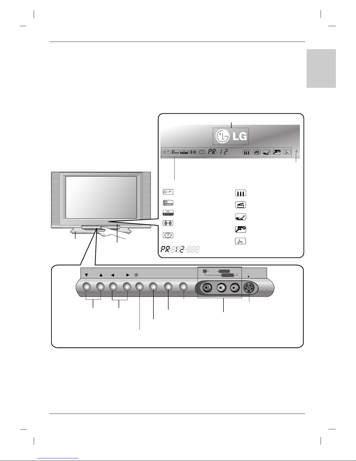
- This is a simplified representation of front panel.
- Here shown may be somewhat different from your TV.
PR VOL OK MENU
ON/OFFINPUT
RR AUDIOAUDIO VIDEOVIDEO
S-VIDEOS-VIDEO
L/MONOL/MONO
AV4
INPUT Button
Volume
(F / G)
Buttons
Remote Control
Sensor
Programme
(
EE/ DD
)
Buttons
MENU Button
OK Button
ON/OFF Button
Stand (option)
S-VIDEO Input
AV4 (Audio/Video) Input
Logo light (Refer to p.39)
Child Lock On mode
(Refer to p.38)
Progressive signal input
PC signal input
SSM-SRS TSXT mode
(Refer to p.32)
Sleep timer mode
(Refer to p.37)
SSM-Flat mode
(Refer to p.32)
SSM-Movie mode
(Refer to p.32)
SSM-Music mode
(Refer to p.32)
SSM-Sports mode
(Refer to p.32)
SSM-User mode
(Refer to p.32)
Programme
number
Power/Standby Indicator
(rr)
• illuminates red in standby mode.
• illuminates green when the set is
switched on.
Index
Controls
Controls
Introduction
Introduction
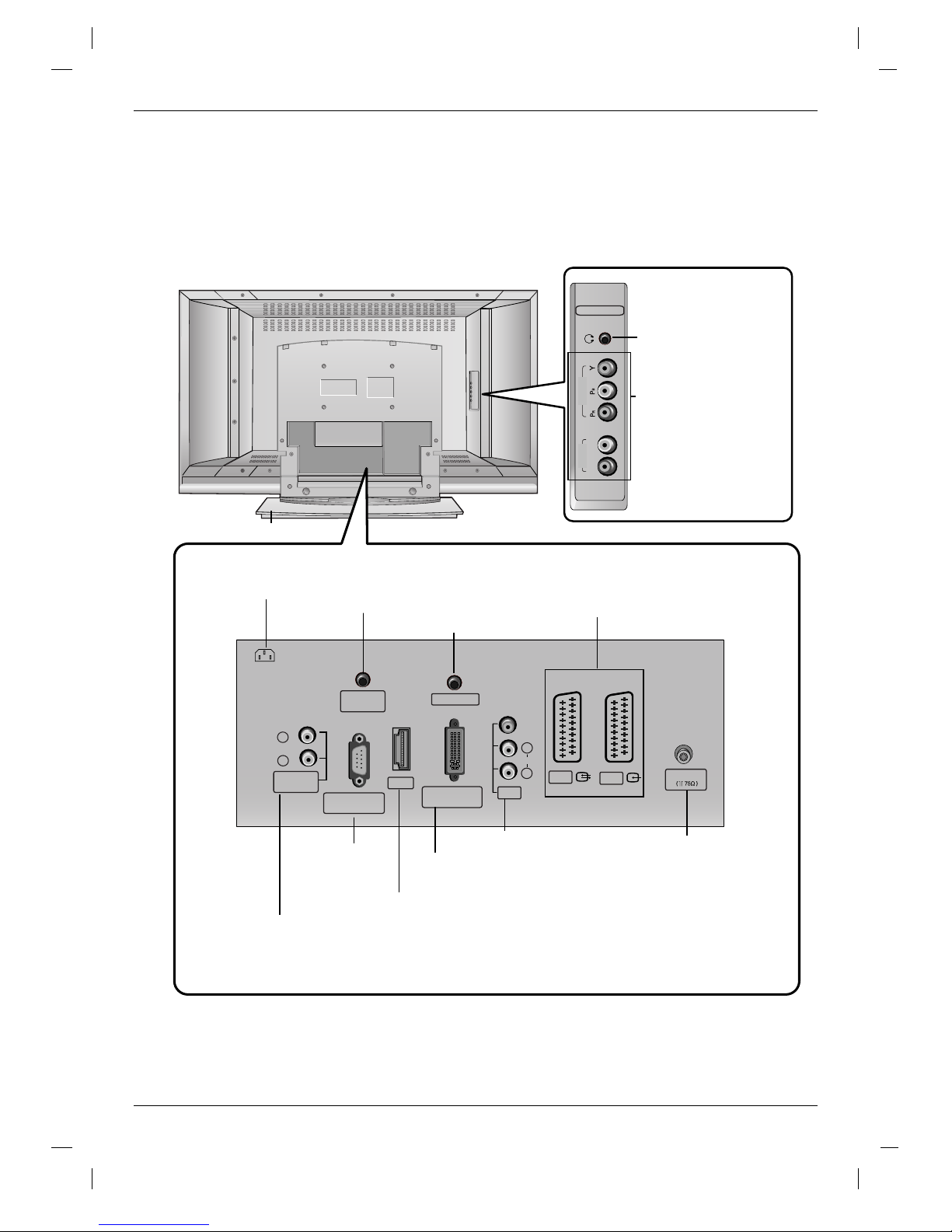
6
R
L
COMPONENT
AUDIO
VIDEO
VIDEO
AUDIO
(MONO)
HDMI
AV1
AV2
AV3
PC SOUND
RS-232C INPUT
(CONTROL/SERVICE)
REMOTE
CONTROL
DVI INPUT
(PC/DTV INPUT)
L
R
L
R
VARIABLE
AUDIO OUT
Antenna
AC IN
COMPONENT input
(Y,PB,PR / Audio)
Headphone Socket
PC SOUND Input
Remote Control Port
Euro Scart Socket
(AV1/AV2)
HDMI (High Definition Multimedia Interface) input
RS-232C Input
Variable AUDIO OUT ports
DVI Input
(PC/DTV Input)
AV3 (Video/Audio) Input
Antenna Input
AC Input
Connection Options
Connection Options
Introduction
Introduction
Stand (option)
7
ENGLISH
TV
FAVOURITE
Q.VIEW
POWER
1 2 3
4 5 6
7809
AUDIO
TEXT
PIP
CABLE
ZOOM
-
ZOOM
+
PSM
SSM
STB
SLEEP
I/II
MENU
ARC
VCR
DVD
MODE
OK
POSITION
TIME
REVEAL
?
MODE
M
MIX
SIZE
HOLD
INDEX
i
INPUT
TV
PIP PR-
PIP PR+
SWAP
PIP INPUT
VOL
PR
MUTE
LIST
EXIT
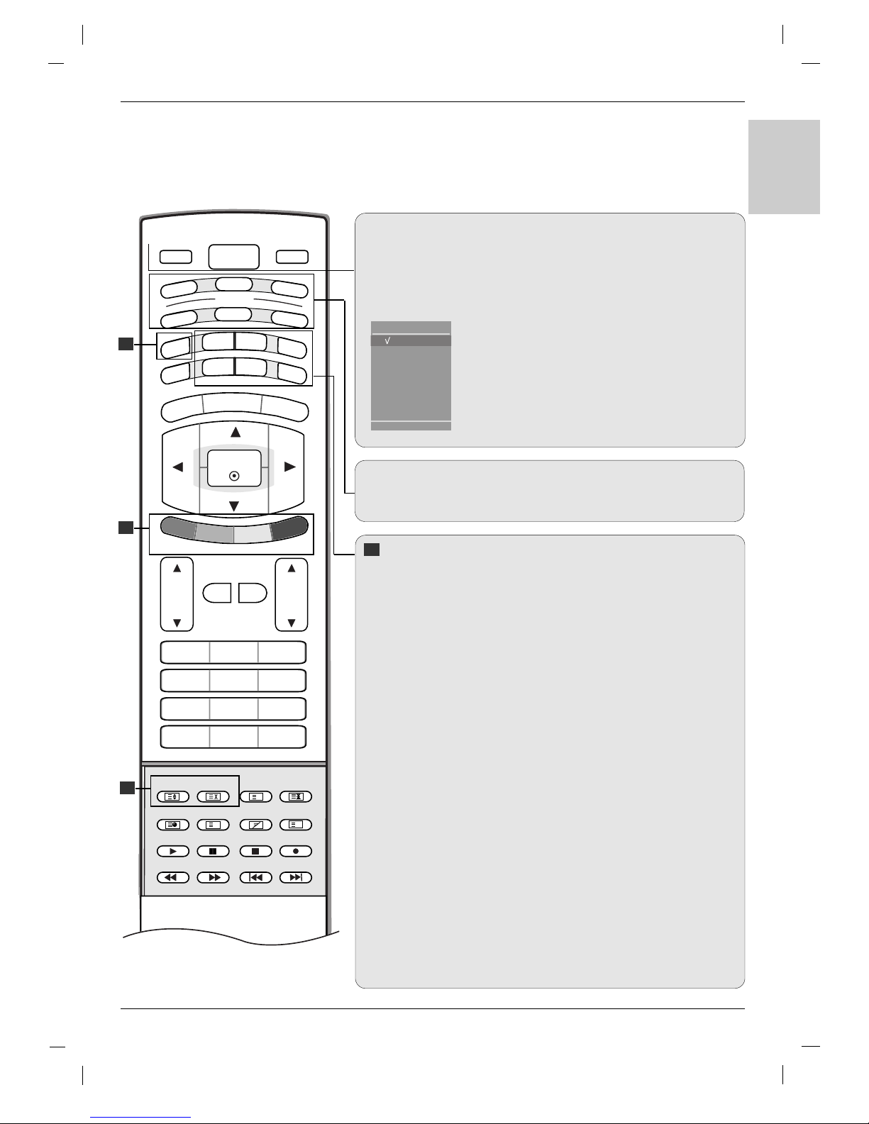
MODE
Selects the remote operating modes. :TV, DVD, VCR, AUDIO, CABLE
or STB
PIP BUTTONS
PIP (Refer to p.46)
Switches the sub picture PIP, DW, POP or off mode.
PIP PR - /+ (Refer to p.49)
Selects a programme for the sub picture.
SWAP (Refer to p.49)
Alternates between main and sub picture.
PIP INPUT (Refer to p.46)
Selects the input mode for the sub picture.
SIZE (Refer to p.47)
Adjusts the sub picture size.
POSITION (Refer to p.47)
Moves the sub picture to
DD /EE
or
FF / GG
direction.
*
COLOURED BUTTONS : These buttons are used for teletext (only
TELETEXT models) or Programme edit.
ZOOM - / ZOOM +
Enlarges or reduces the main picture size.
SLEEP
Sets the sleep timer. (Refer to p.37)
SSM (Sound Status Memory)
Recalls your preferred sound setting. (Refer to p.32)
PSM (Picture Status Memory)
Recalls your preferred picture setting. (Refer to p.29)
I/II
• Selects the sound output.
Remote Control Key Functions
Remote Control Key Functions
TV
Returns to TV viewing from any mode.
POWER
switches the set on from standby or off to standby.
INPUT
If you press the button once, the input source OSD
will appear on screen as shown. Press the
DD / EE
button and then OK button to select the desired input
source (
TV, AV 1 , AV 2 , AV 3 , AV 4 , S-Video,
Component, DVI PC/DVI DTV, or HDMI PC/
HDMI DTV).
1
1
1
1
TV
AV1
AV2
AV3
AV4
S-Video
Component
DVI PC
HDMI PC
TV
Input
8
TV
FAVOURITE
Q.VIEW
POWER
1 2 3
4 5 6
7809
AUDIO
TEXT
PIP
CABLE
ZOOM
-
ZOOM
+
PSM
SSM
STB
SLEEP
I/II
MENU
ARC
VCR
DVD
MODE
OK
POSITION
TIME
REVEAL
?
MODE
M
MIX
SIZE
HOLD
INDEX
i
INPUT
TV
PIP PR-
PIP PR+
SWAP
PIP INPUT
VOL
PR
MUTE
LIST
EXIT
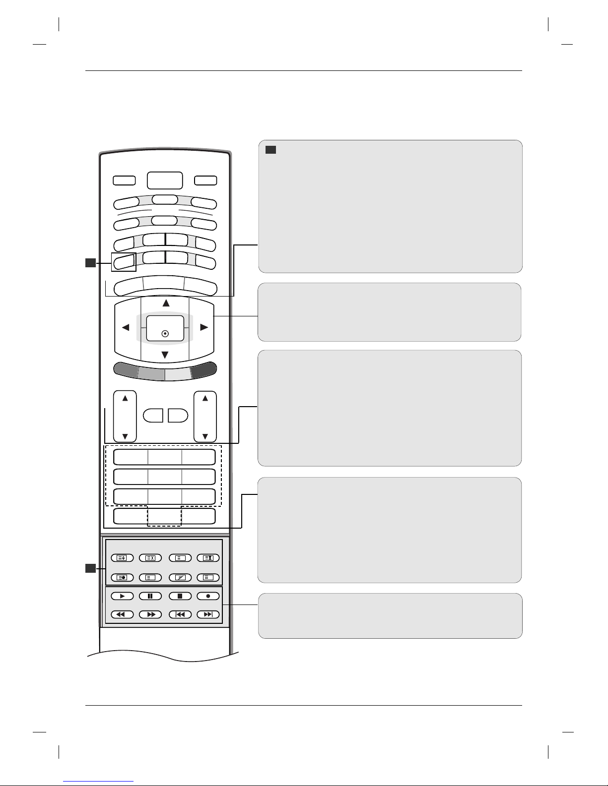
Remote Control Key Functions
Remote Control Key Functions
Introduction
Introduction
TELETEXT BUTTONS
These buttons are used for teletext.
For further details, see the ‘Teletext’ section (Refer to p.50).
MENU
Selects a menu.
ARC
Selects your desired picture format (Refer to p.42).
EXIT
Clears all on-screen displays and returns to TV viewing from any
menu.
DD/EE
/ F / G (up / down / left / right)
Selects or adjusts an item in the menu.
OK
Accepts your selection or displays the current mode.
VOL (Volume) D / E
Adjusts the volume.
MUTE
Switches the sound on or off.
LIST
Displays the programme table (Refer to p.28).
PR (Programme)
D / E
Selects a programme.
0-9 number buttons
• Selects a programme.
• Selects numbered items in a menu.
FAVOURITE
Displays the se
lected favourite programme
(Refer to p.28).
Q.VIEW
Returns to the previously viewed programme.
VCR/DVD Control buttons
Controls a LG video cassette recorder or DVD.
2
2
2
9
ENGLISH
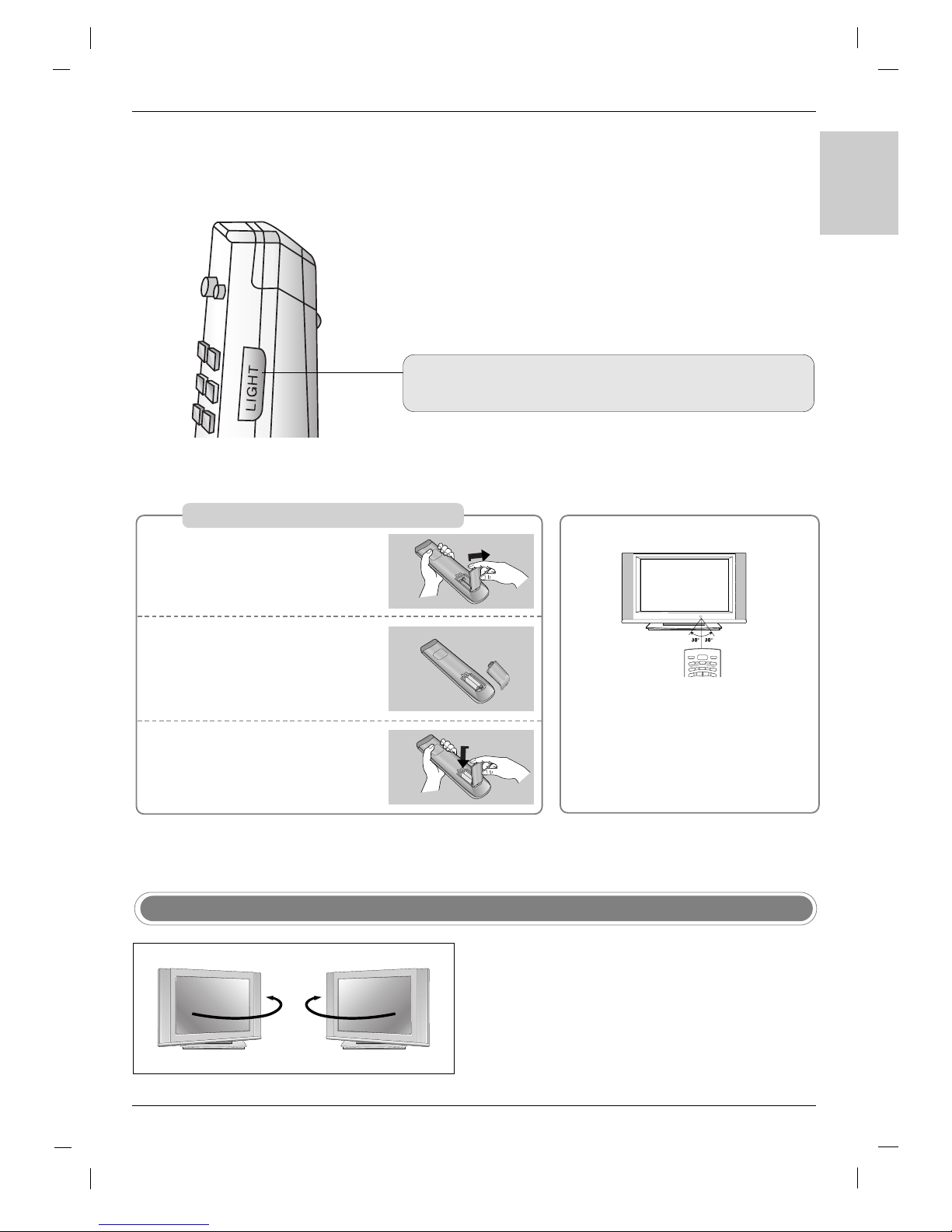
Installing Batteries
Open the battery compartment
cover on the back side.
Insert two 1.5V AA size batteries
in correct polarity (+ with +, - with
-). Don’t mix old or used batteries
with new ones.
Close the cover.
* Use a remote control 7 meter dis-
tance and 30 degree (left/right) within the receiving unit scope.
* Dispose of used batteries in the recycle bin to prevent environment.
TV
POWER
A
U
D
IO
P
I
P
CABLE
Z
O
O
M
-
Z
O
O
M
+
STB
S
LEEP
V
C
R
DVD
MODE
INPUT
T
V
1
2
3
- The TV can be conveniently swiveled on its stand 30° to
the left or right to provide the optimum viewing angle.
Swivel Stand (option)
LIGHT
Illuminates the remote control buttons.
10
4 inches
4 inches
4 inches4 inches
4 inches
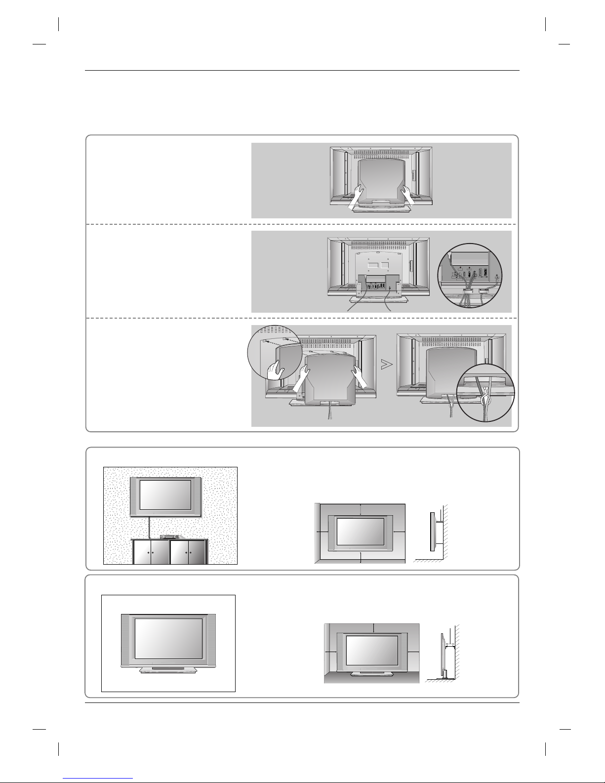
For proper ventilation, allow a clearance of 4" on each side and from
the wall. Detailed installation instructions are available from your
dealer, see the optional Tilt Wall Mounting Bracket Installation and
Setup Guide.
Wall Mount: Horizontal installation
Desktop Pedestal Installation
4 inches
4 inches4 inches
4 inches
For proper ventilation, allow a clearance of 4" on each side and from
the wall.
Hold the cover with both hands
and pull it backward.
Connect the cables as necessary.
After connecting the cables neatly,
arrange the cables to the Cable
Holder (option).
To connect an additional equipment,
see the External equipment
Connections section.
Align the holes on the TV back
panel with the protuberances on
the back cover and insert.
Pull the cables through the hole
on the set and bundle the cables
using the supplied twister holder.
1
2
3
VIDEO
AUDIO
HDMI
AV1
AV2
AV3
PC SOUND
RS-232C INPUT
(CONTROL/SERVICE)
REMOTE
CONTROL
DVI INPUT
(PC/DTV INPUT)
L
R
L
R
VARIABLE
AUDIO OUT
Antenna
Antenna
LOOP THROUGH
UPGRADE
PORT
HDMI
MONITOR
OUT
REMOTE
CONTROL
DVI INPUT
(PC INPUT)
PC SOUND
AV1
AV2
VIDEO
L
AUDIO
R
Antenna
LOOP THROUGH
UPGRADE
PORT
HDMI
MONITOR
OUT
REMOTE
CONTROL
DVI INPUT
(PC INPUT)
PC SOUND
AV1
AV2
VIDEO
L
AUDIO
R
Antenna
LOOP THROUGH
UPGRADE
PORT
HDMI
MONITOR
OUT
REMOTE
CONTROL
DVI INPUT
(PC INPUT)
PC SOUND
AV1
AV2
VIDEO
L
AUDIO
R
Basic Connection
Basic Connection
Installation
Installation
VIDEO
AUDIO
HDMI
AV1
AV2
AV3
PC SOUND
RS-232C INPUT
(CONTROL/SERVICE)
REMOTE
CONTROL
DVI INPUT
(PC/DTV INPUT)
L
R
L
R
VARIABLE
AUDIO OUT
Antenna
11
ENGLISH
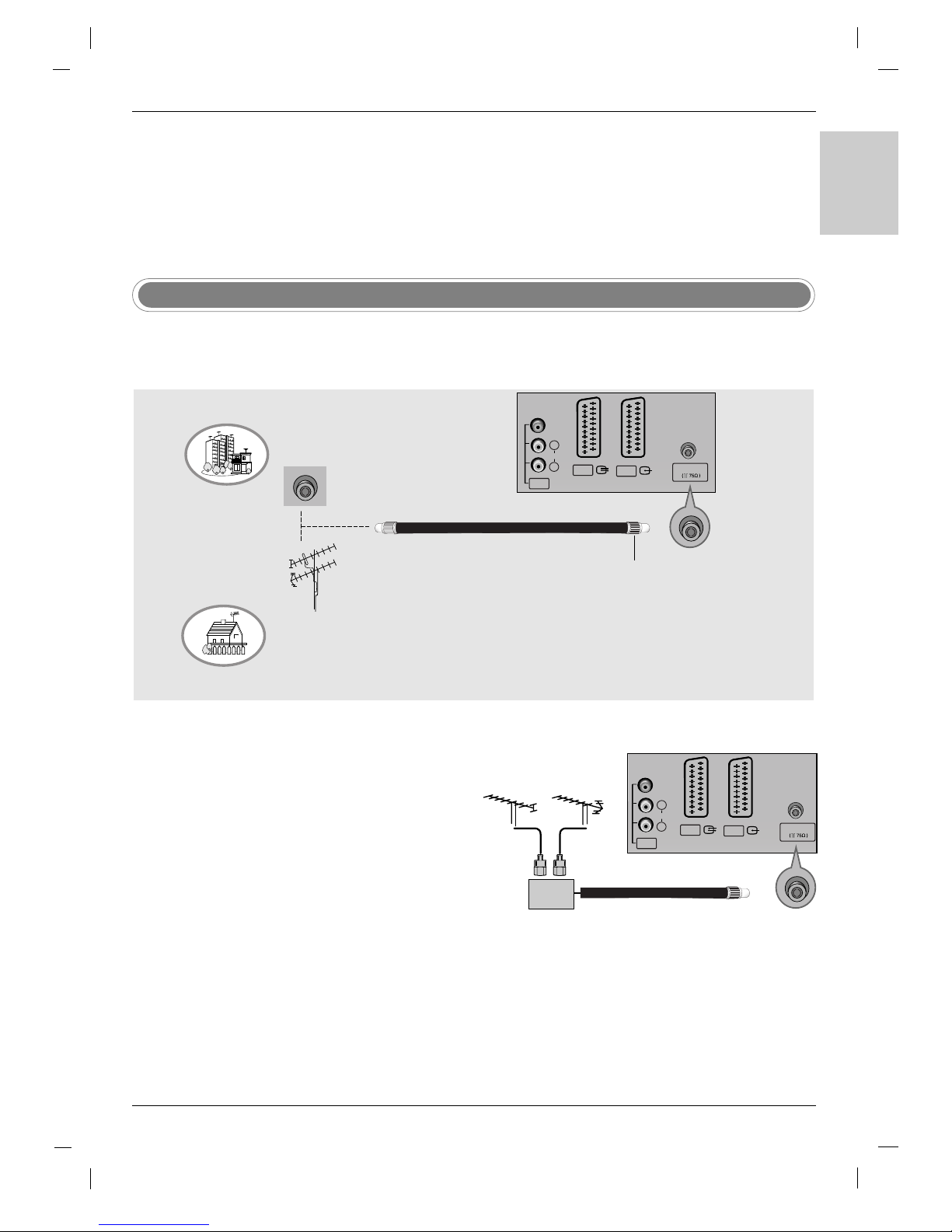
Antenna Connection
- For optimum picture quality, adjust antenna direction.
- An antenna cable and converter are not supplied.
To prevent the equipment damage, never plug in any power cords until you have finished connecting all
equipment.
• In poor signal areas, to get better picture quality, install a sig-
nal amplifier to the antenna as shown to the right.
•
If signal needs to be split for two TVs, use an antenna signal splitter for connection.
Signal
Amplifier
UHF
VHF
Multi-family Dwellings/Apartments
(Connect to wall antenna socket)
Single-family Dwellings /Houses
(Connect to wall jack for outdoor antenna)
Outdoor Antenna
Wall Antenna Socket
VHF Antenna
UHF Antenna
RF Coaxial Wire (75 ohm)
Turn clockwise to tighten.
VIDEO
AUDIO
AV1
AV2
AV3
L
R
Antenna
(MONO)
VIDEO
AUDIO
AV1
AV2
AV3
L
R
Antenna
(MONO)
External Equipment Connections
External Equipment Connections
12
- To avoid picture noise (interference), leave an adequate distance between the VCR and TV.
- Typically a frozen still picture from a VCR. If the 4:3 picture format is used; the fixed images on the sides of the
screen may remain visible on the screen.
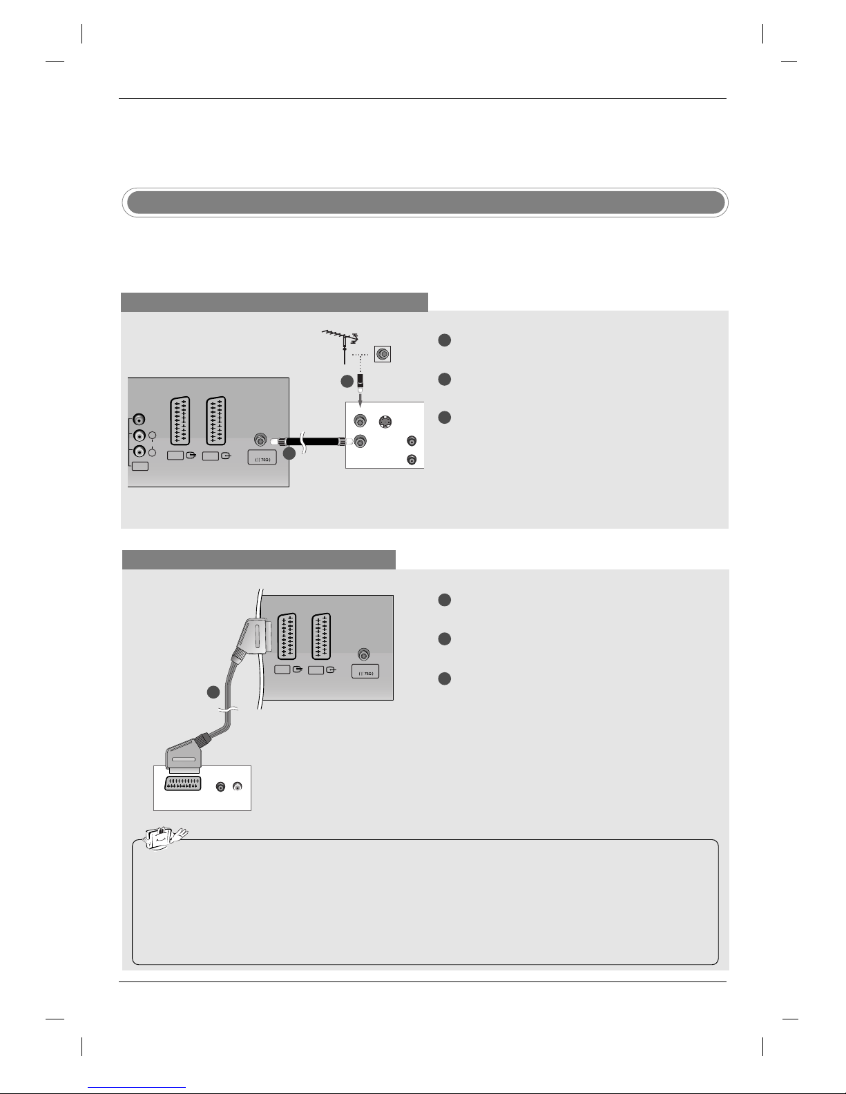
VCR Setup
When connecting with an antenna cable
1
2
3
S-VIDEO
OUT
IN
(R) AUD
ANT OUT
ANT IN
VIDEO
AUDIO
AV1
AV2
AV3
L
R
Antenna
(MONO)
Connect the ANT OUT socket of the VCR to the
Antenna socket on the set.
Connect the antenna cable to the ANT IN socket
of the VCR.
Press the PLAY button on the VCR and match the
appropriate programme between the TV and VCR
for viewing.
When connecting with a Scart cable
• If your VCR outputs an AV switching signal via the AV1 or AV2 scart sockets, the set will switch to AV1 input source automati-
cally. But if you want to keep on watching TV mode, press the PR
DD /EE
or number buttons.
• You can also record programmes received by the TV on video tape.
• The signal type RGB (the signals red, green and blue) can only be selected for the AV1 scart socket and the AV1 input source
can be received. These signals are transmitted, for example, by a pay TV decoder, game machine or photo CD unit, etc and that
digital signal can be recorded via AV1 scart socket.
• If the AV 1, AV2 scart sockets have been connected to the VCRs simultaneously, only the AV2 input source can be received.
• In AV2 scart socket, the video output is not available.
(R) AUDIO (L)
AUDIO/
VIDEO
AV1
AV2
Antenna
1
2
3
Connect the scart socket of the VCR to the AV1 scart
socket on the set. Please use shielded scart cable.
Insert a video tape into the VCR and press PLAY on
the VCR. (Refer to the VCR owner’s manual.)
Select
AV 1 input source with using the INPUT button
on the remote control.
- If connected to AV2 scart socket, select
AV 2 input
source.
1
2
TV Back panel
VCR
VCR
TV Back panel
1
External Equipment Connections
External Equipment Connections
Installation Instruction
Installation Instruction
13
ENGLISH
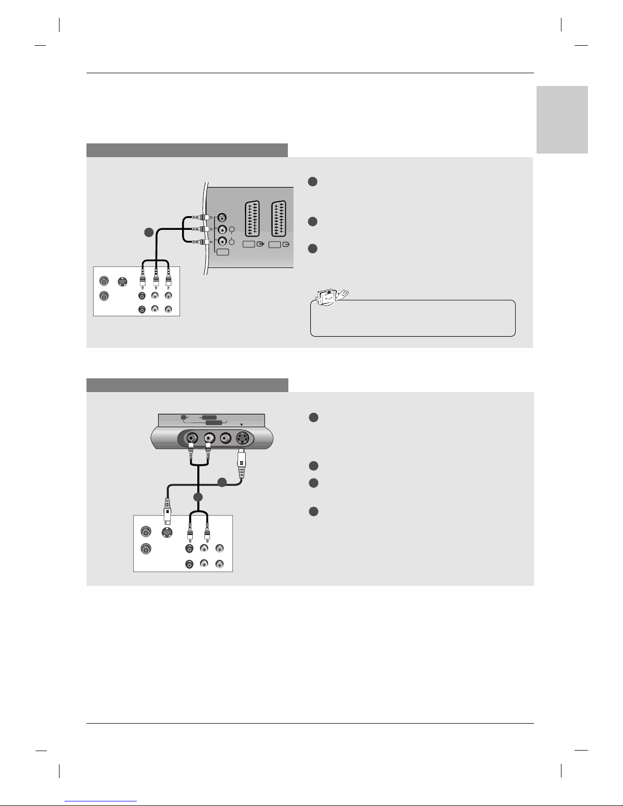
When connecting with a RCA cable
S-VIDEO
OUT
IN
(R) AUDIO (L)
VIDEO
ANT OUT
ANT IN
VIDEO
AUDIO
AV1
AV2
AV3
L
R
(MONO)
VCR
TV Back panel
1
1
2
3
Connect the AUDIO/VIDEO jacks between TV
and VCR. Match the jack colours (Video = yellow,
Audio Left = white, and Audio Right = red)
Insert a video tape into the VCR and press PLAY
on the VCR. (Refer to the VCR owner’s manual.)
Select
AV 3 input source with using the INPUT
button on the remote control.
- If connected to AV4 on front, select
AV 4 input
source.
• If you have a mono VCR, connect the audio cable
from the VCR to the AUDIO L/MONO jack of the set.
When connecting with an S-Video cable
S-VIDEO
OUT
IN
(R) AUDIO (L)
VIDEO
ANT OUT
ANT IN
RR AUDIOAUDIO VIDEOVIDEO
S-VIDEOS-VIDEO
L/MONOL/MONO
AV4
VCR
TV front
1
1
2
2
3
4
Connect the S-VIDEO output of the VCR to the SVIDEO input on the set. The picture quality is
improved; compared to connecting a regular VCR
to the Video input.
Connect the AUDIO jacks between TV and VCR.
Insert a video tape into the VCR and press PLAY
on the VCR. (Refer to the VCR owner’s manual.)
Select
S-Video input source with using the
INPUT button on the remote control.
14
External Equipment Connections
External Equipment Connections
Installation
Installation
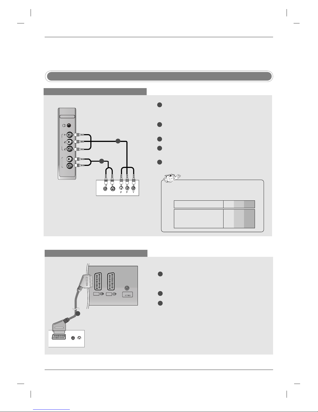
When connecting with a Euro scart cable
(R) AUDIO (L)
AUDIO/
VIDEO
AV1
AV2
Antenna
DVD
1
1
2
3
Connect the Euro scart socket of the DVD to the AV1
Euro scart socket on the set. Please use shielded
scart cable.
Turn on the DVD player, insert a DVD.
Select
AV 1 input source with using the INPUT button
on the remote control.
- If connected to AV2 Euro scart socket, select
AV 2
input source.
DVD Setup
When connecting with a component cable
R
L
COMPONENT
AUDIO
VIDEO
B
R
(R) AUDIO (L)
DVD
TV side panel
1
1
2
2
3
4
5
Connect the video outputs (Y, PB
, PR) of the DVD
to the COMPONENT VIDEO (Y, P
B, PR) jacks on
the set.
Connect the audio outputs of the DVD to the
COMPONENT AUDIO jacks on the set.
Turn on the DVD player, insert a DVD.
Select
Component input source with using the
INPUT button on the remote control.
Refer to the DVD player's manual for operating
instructions.
• Component Input ports
To get better picture quality, connect a DVD player
to the component input ports as shown below.
Y PB
PR
Component ports on the TV
Y
Y
Y
Y
Pb
B-Y
Cb
PB
Pr
R-Y
Cr
PR
Video output ports
on DVD player
TV Back panel

15
ENGLISH
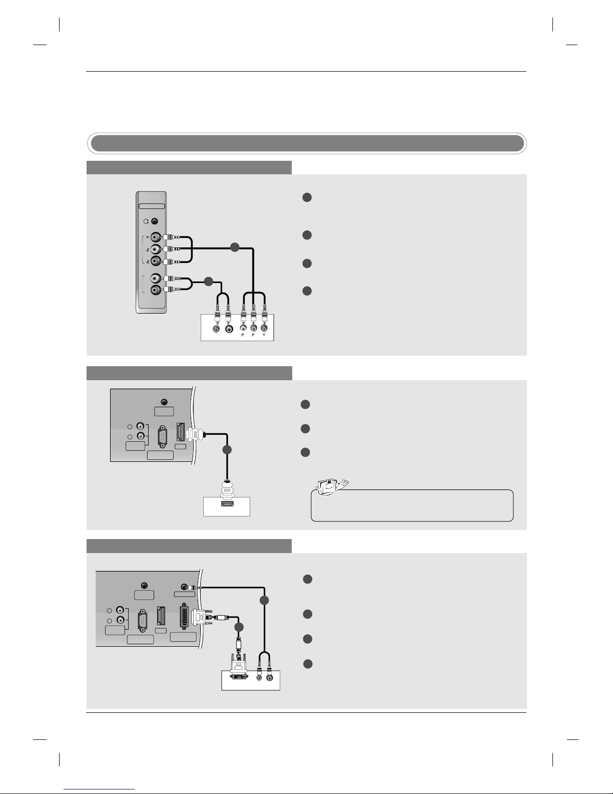
When connecting with a HDMI cable
HDMI OUTPUT
HDMI
RS-232C INPUT
(CONTROL/SERVICE)
REMOTE
CONTROL
L
R
VARIABLE
AUDIO OUT
DVD
1
1
2
3
Connect the HDMI output of the DVD to the HDMI
jack on the set.
Select
HDMI DTV input source with using the
INPUT button on the remote control.
Refer to the DVD player's manual for operating
instructions.
• TV can receive the video and audio signal simultaneously with using a HDMI cable.
TV Back panel
(R) AUDIO (L)
DVI-DTV OUTPUT
HDMI
PC SOUND
RS-232C INPUT
(CONTROL/SERVICE)
REMOTE
CONTROL
DVI INPUT
(PC/DTV INPUT)
L
R
VARIABLE
AUDIO OUT
HDMI-DTV OUTPUT
HDMI
RS-232C INPUT
(CONTROL/SERVICE)
REMOTE
CONTROL
L
R
VARIABLE
AUDIO OUT
R
L
COMPONENT
AUDIO
VIDEO
B
R
(R) AUDIO (L)
16
When connecting with a component cable
When connecting with a HDMI cable
1
1
2
2
3
4
Connect the video outputs (Y, PB, PR) of the digital settop box to the COMPONENT VIDEO (Y, PB, PR) jacks
on the set.
Connect the audio outputs of the digital set-top box to
the COMPONENT AUDIO jacks on the set.
Turn on the digital set-top box. (Refer to the owner’s
manual for the digital set-top box.)
Select
Component input source with using the
INPUT button on the remote control.
1
1
2
3
Connect the HDMI output of the digital set-top box to
the HDMI jack on the set.
Turn on the digital set-top box. (Refer to the owner’s
manual for the digital set-top box.)
Select
HDMI DTV input source with using the INPUT
button on the remote control.
DTV Receiver (Set-top Box)
DTV Receiver (Set-top Box)
STB ( Set-Top Box) Setup
When connecting with a DVI cable
1
1
2
2
3
4
Connect the DVI output of the digital set-top box
to the DVI INPUT (PC / DTV INPUT) jack on the
set.
Connect the audio outputs of the set-top box to
the PC SOUND jack on the set.
Turn on the digital set-top box. (Refer to the
owner’s manual for the digital set-top box.)
Select
DVI DTV input source with using the
INPUT button on the remote control.
DTV Receiver (Set-top Box)
External Equipment Connections
External Equipment Connections
Installation
Installation
TV side panel
TV Back panel
TV Back panel
• TV can receive the video and audio signal simultaneously with using a HDMI cable.
17
ENGLISH
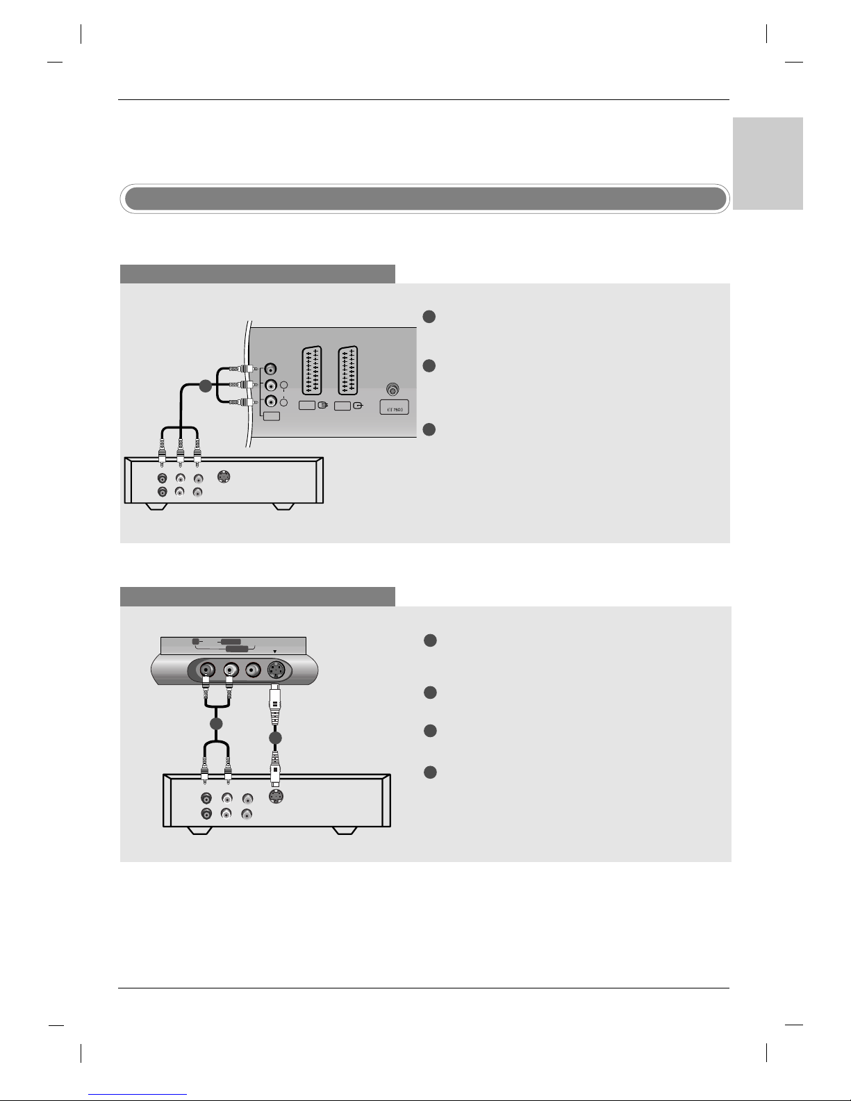
Cable TV Setup
- After subscribing to a local cable TV service and installing a converter, you can watch cable TV programming.
- For further cable TV information, contact a local cable service provider.
When connecting with a RCA cable
TV
VCR
VIDEO
VIDEO
AUDIO
AV1
AV2
AV3
L
R
Antenna
(R) AUDIO (L)
S-VIDEO
(MONO)
Cable Box
TV Back panel
1
1
2
3
Connect the AUDIO/VIDEO jacks between TV and
Cable Box. Match the jack colours (Video = yellow,
Audio Left = white, and Audio Right = red)
Select
AV 3 input source with using the INPUT
button on the remote control.
- If connected to AV4 on front, select
AV 4 input
source.
Select programmes with the cable box remote control.
When connecting with an S-Video cable
TV
VCR
(R) AUDIO (L)
VIDEO
S-VIDEO
RR AUDIOAUDIO VIDEOVIDEO
S-VIDEOS-VIDEO
L/MONOL/MONO
AV4
TV front
1
1
2
2
3
4
Connect the S-VIDEO output of the Cable Box to
the S-VIDEO input on the set. The picture quality
is improved.
Connect the AUDIO jacks between TV and Cable
Box.
Select
S-Video input source with using the
INPUT button on the remote control.
Select programmes with the cable box remote control.
Cable Box
18
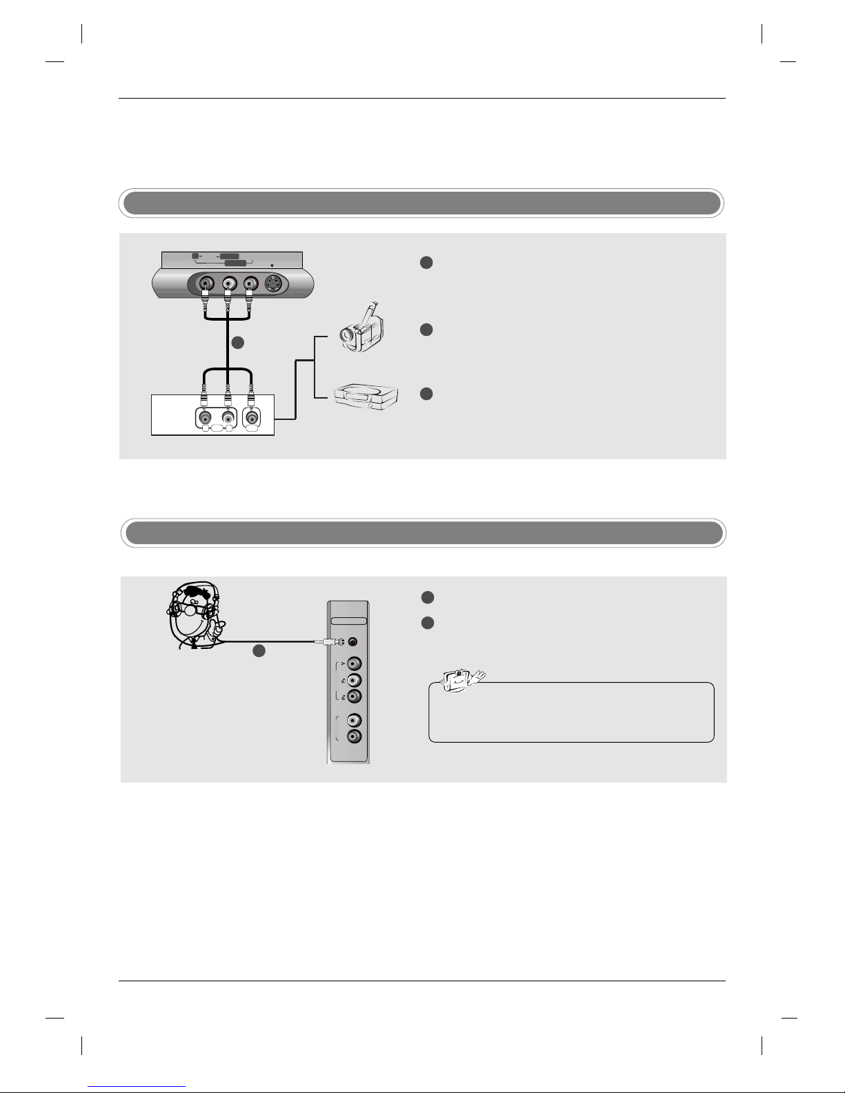
RL
AUDIO VIDEO
RR AUDIOAUDIO VIDEOVIDEO
S-VIDEOS-VIDEO
L/MONOL/MONO
AV4
Camcorder
Video Game Set
TV front
1
1
2
3
Connect the AUDIO/VIDEO jacks between TV
and external equipment. Match the jack colours
(Video = yellow, Audio Left = white, and Audio
Right = red).
Select
AV 4 input source with using the INPUT
button on the remote control.
- If connected to S-VIDEO on front, select
S-Video
input source.
Operate the corresponding external equipment.
Refer to external equipment operating guide.
External AV Source Setup
Headphone Socket
1
2
Plug the headphone into the headphone socket.
To adjust the headphone volume, press the VOL
DD /EE
button. If you press the MUTE button, the
sound from the headphone is switched off.
R
L
COMPONENT
AUDIO
VIDEO
- You can listen to the sound through the headphone.
• While you are listening to sound through a headphone,
TV speakers will not be heard.
1
External Equipment Connections
External Equipment Connections
Installation
Installation

19
ENGLISH
Connect the DVI output of the PC to the HDMI
jack on the set.
Connect the PC audio output to the PC SOUND
jack on the set.
Turn on the PC and the set.
Select
HDMI PC input source with using the
INPUT button on the remote control.
PC Setup
1
2
3
4
Connect the TV to the PC with the PC cable.
Connect the PC audio output to the TV's PC SOUND input.
Turn on the PC.
Select
DVI PC input source with using the INPUT
button on the remote control.
HDMI
PC SOUND
RS-232C INPUT
(CONTROL/SERVICE)
REMOTE
CONTROL
DVI INPUT
(PC/DTV INPUT)
IO OUT
NOTE
Connect the signal cable (DVI-D cable, Not DVI to D-Sub
cable) from the DVI output socket of the PC to the DVI
input socket of the set when using a PC with DVI output.
In some video cards, DVI-Analog output may not be supported.
When connecting with a HDMI to DVI cable
When connecting with a DVI-D cable or a DVI to D-Sub cable
1
2
3
4
DVI OUTPUT AUDIO
HDMI
PC SOUND
RS-232C INPUT
(CONTROL/SERVICE)
REMOTE
CONTROL
L
R
VARIABLE
AUDIO OUT
1
PC
PC
TV Back panel
TV Back panel
• If the PC has a DVI output and no HDMI output, a
separated audio connection is necessary.
• It’s not available to connect with a HDMI to DVI
cable to the DVI INPUT jack on the set.
20
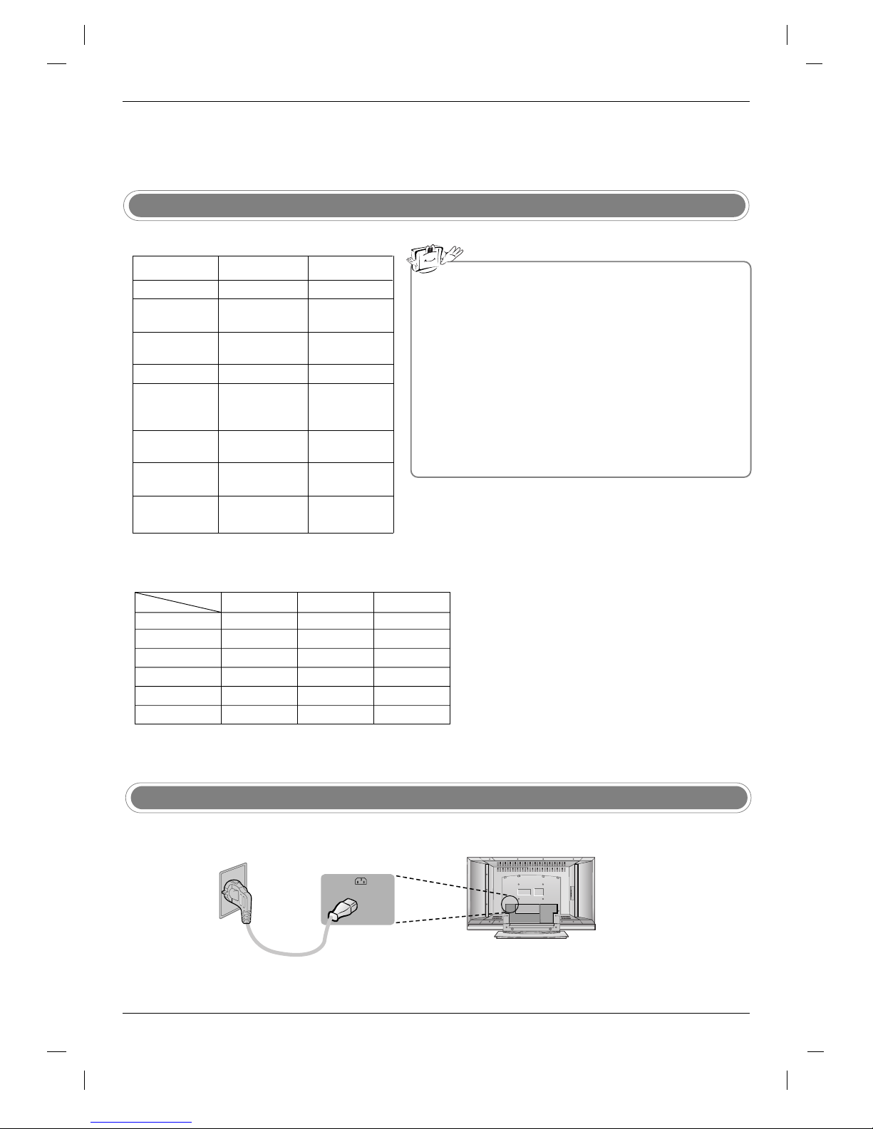
AC IN
- Connect the power cord correctly as shown.
Power Cord Connection
External Equipment Connections
External Equipment Connections
Installation
Installation
Resolution
Horizontal
Frequency(kHz)
Vertical
Frequency(Hz)
Supported display resolution
DPM (Display Power Management) mode
If the PC goes to power saving mode, the monitor automatically
switches to DPM mode.
If you don’t use the PC cable provided, DPM mode may not work.
- DPM mode is not available in HDMI PC mode.
Note
a. For optimum picture quality, use standard WXGA
1360x768 computer output at a 60Hz refresh rate.
Using other formats (VGA, SVGA, etc.) or refresh
rates may result in reduced picture quality. (To
change the computer video output format, please
refer to the operating manual for the computer you
are using).
b. If the message
No signal appears on the screen,
adjust the PC output to a format listed in the
Monitor Display Specifications table.
c. The synchronization input form for Horizontal and
Vertical frequencies is separate.
720 x 400
640 x 480
800 x 600
832 x 624
1024 x 768
(XGA)
1280 x 768
(WXGA)
1360 x 768
(WXGA)
1366 x 768
(WXGA)
31.468
31.469
37.500
37.879
46.875
49.725
48.363
56.470
60.123
47.776
47.720
47.720
70
60
75
60
75
75
60
70
75
60
60
60
AA
PC (Monitor Display Specifications)
AA
DTV
480i
576i
480p
576p
720p
1080i
Mode
Component
o
o
o
o
o
o
DVI (DTV)
x
x
o
o
o
o
HDMI (DTV)
x
x
o
o
o
o
Terminal
 Loading...