

LG 37LH50YD User Manual
ENGLISH
OWNER’S MANUAL
LCD TV MODELS
2222LLUU55******
2266LLUU55******
2222LLHH22******
2266LLHH22******
3322LLHH22******
3377LLHH22******
4422LLHH22******
3322LLHH33******
3377LLHH33******
4422LLHH33******
LCD TV
Please read this manual carefully before operating
your TV.
Retain it for future reference.
Record model number and serial number of the TV.
Refer to the label on the back cover and quote this
information.
To your dealer when requiring service.
IIDD NN uu mm bbee rr ((ss ))::
6548 : 22LU50FD
6550 : 26LU50FD
6530 : 22LH20D
6531 : 26LH20D
6532 : 32LH20D
6533 : 37LH20D
6534 : 42LH20D
6535 : 32LH35FD
6536 : 37LH35FD
6537 : 42LH35FD
6538 : 32LH50YD
6539 : 37LH50YD
6540 : 42LH50YD
6541 : 47LH50YD
6542 : 55LH50YD
6543 : 47LH80YD
6544 : 55LH80YD
6545 : 42LH90QD
6546 : 47LH90QD
DVB is a registered trademark
of the DVB Project
3322LLHH55******
3377LLHH55******
4422LLHH55******
4477LLHH55******
5555LLHH55******
4477LLHH88******
5555LLHH88******
4422LLHH99******
4477LLHH99******
This product qualifies for ENERGY STAR in the “factory
default (Home Use mode)” setting and this is the setting in
which power savings will be achieved.
Changing the factory default picture setting or enabling other
features will increase power consumption that could exceed
the limits necessary to qualify for Energy Star rating.
((EExxcceepptt ffoorr SSiinnggaappoorree))

1
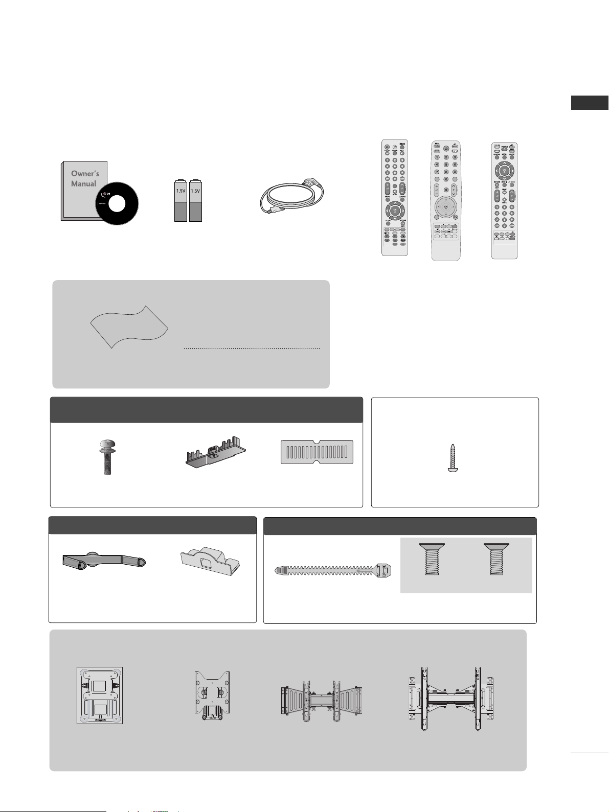
ACCESSORIES
ACCESSORIES
Ensure that the following accessories are included with your TV. If an accessory is missing, please contact the
dealer where you purchased the TV.
■
Here shown may differ from your TV.
Owner’s Manual
Batteries
Remote Control
Power Cord
Polishing Cloth
Polishing cloth for use on
the screen.
This item is not included for all models.
* Lightly wipe any stains or
fingerprints on the surface
of the TV with the polishing
cloth.
Do not use excessive force. This
may cause scratching or discolouration.
Wall Mounting Bracket(Separate purchase)
AW-47LG30M
(Only 32/37/42LH2***,
32/37/42LH3***,
32/37/42/47LH5***,
42/47LH9***)
or
AV MODEV MODE
ENERGYENERGY SA SAVINGVING
RETURN / EXIT
MENU
Q.MENU INFO GUIDE
i
MUTEMUTE
POWERPOWER
LISTLIST
Q.VIEWQ.VIEW
MARK
FAV
OOnnllyy 2222LLHH22******
Protection cover
(Refer to p.12)
Cable management clip
(Refer to p.14)
(22LU5***, 22LH2
***
)
RW120
(26LU5***, 26/32LH2
***,
32LH3
***,
32LH5
***
)
RW230
AW-55LH40M
(55LH5***)
POWERPOWER
TV/RAD
ON/OFFON/OFF
RATIO
AV MODEV MODE
MARKMARK
FAV
or
Bolts for stand assembly
(Refer to p.11)
x 4
OOnnllyy 2266//3322//3377//4422LLHH22******,, 3322//3377//4422LLHH33******,,
3322//3377//4422//4477//5555LLHH55******,, 4422//4477LLHH99******
Protection cover
(Refer to p.12)
1-screw for stand fixing
(Refer to p.13)
(Only 26LU5***, 26/32/37/42LH2***,
32/37/42LH3***, 32/37/42LH5***, 42LH9***)
(Except for 55LH5***)
or
Bolts for stand assembly
(Refer to p.11)
Cable Holder
(Refer to p.15)
Only 22/26LU5
***
(Only 22LU5
***
)
(Only 26LU5
***
)
x 2 x 3

CONTENTS
2
CONTENTS
ACCESSORIES
. . . . . . . . . . . . . . . . . . . . . . . . . . . . . . . . . . . . . . . . . . . .
1
PREPARATION
Front Panel Controls..................................................... 4
Back Panel Information ................................................ 8
Stand Installation......................................................... 11
Not Using the Desk-type Stand ...............................12
Attaching the TV to a Desk .....................................13
Detaching Stand ........................................................13
Back Cover for Wire Arrangement.......................... 14
Positioning your display .........................................15
Swivel Stand ..................................................................15
Careful installation advice ..................................... 15
Desktop Pedestal Installation ............................... 16
Wall Mount: Horizontal Installation........................ 16
Antenna Connection................................................... 17
EXTERNAL EQUIPMENT SETUP
HD Receiver Setup...................................................... 18
DVD Setup..................................................................... 21
VCR Setup..................................................................... 23
Digital Audio Out Setup ........................................... 25
Other A/V Source Setup .......................................... 26
Usb Setup...................................................................... 27
PC Setup........................................................................ 28
- Screen Setup for PC Mode................................32
WATCHING TV / PROGRAMME CONTROL
Remote Control Key Functions ............................... 36
Turning on the TV ........................................................42
Programme Selection ................................................ 42
Volume Adjustment ................................................... 42
Quick Menu ................................................................. 43
On-Screen Menus Selection and Adjustment..... 44
Auto Programme Tuning ............................................ 45
Manual Programme Tuning (In Digital Mode) ..... 46
Manual Programme Tuning (In Analogue Mode) .. . 47
Programme Edit ........................................................... 49
Software Update ...........................................................51
Diagnostics ................................................................... 52
Selecting the Programme List .................................. 53
Favourite Programme Setup...................................... 54
Input List........................................................................ 55
Input Label .................................................................... 56
Simple manual .............................................................. 57
................................................................. 58
AV Mode........................................................................ 60
Initializing (Reset to original factory settings) .....61
TO USE A BLUETOOTH
Precautions when using the Bluetooth................. 62
Setting the Bluetooth................................................. 63
Set TV PIN......................................................................64
Bluetooth headset
- Connecting a new Bluetooth headset.............65
- Connecting to Bluetooth headset already
registered ................................................................. 65
-
Disconnecting the Bluetooth headset during use
....66
- When requesting to connect to TV from the
Bluetooth headset....................................................66
Managing Registered Bluetooth device ................ 67
My Bluetooth Information. ........................................68
Receiving Photos from external Bluetooth device.........
69
Listening to the Musics from external Bluetooth device .....
69
TO USE A USB DEVICE
When connecting a USB device.............................. 70
Photo List ...................................................................... 71
Music List........................................................................75
Movie List........................................................................78
DivX Registration Code..............................................82
Deactivation...................................................................83

CONTENTS
3
EPG (ELECTRONIC PROGRAMME
GUIDE) (IN DIGITAL MODE)
Switch on/off EPG ...................................................... 84
Select a Programme.................................................... 84
Button Function in NOW/NEXT Guide Mode ....... 84
Button Function in 8 Day Guide Mode..................85
Button Function in Date Change Mode................ 85
Button Function in Extended Description Box.........
86
Button Function in Remind Setting Mode
......................... 86
Button Function in Schedule List Mode................ 86
MHEG (MULTIMEDIA AND HYPERMEDIA INFORMATION CODING EXPERT
GROUP) (IN DIGITAL MODE)
Switch on MHEG ......................................................... 87
Select a Programme.................................................... 87
Button Function in Guide Mode...............................88
Button Function in NOW/NEXT Guide Mode ....... 88
PICTURE CONTROL
Picture Size (Aspect Ratio) Control ...................... 89
Picture Wizard................................................................91
Energy Saving ................................................................92
Preset Picture Settings
- Picture Mode-Preset............................................ 93
Manual Picture Adjustment
- Picture Mode-User option................................. 94
Picture Improvement Technology ........................... 95
Expert Picture Control............................................... 96
Picture Reset ................................................................ 99
LED Local Dimming..................................................... 99
Power Indicator...........................................................100
Demo Mode................................................................ 101
Mode Setting...............................................................102
SOUND & LANGUAGE CONTROL
Auto Volume Leveler................................................. 103
Clear Voice II ...............................................................104
Preset Sound Settings - Sound Mode................. 105
Sound Setting Adjustment -User Mode ..............106
SRS TruSurround XT .................................................106
Balance......................................................................... 107
TV Speakers On/ Off Setup....................................108
Selecting Digital Audio Out ....................................109
Audio Reset...................................................................110
Stereo Reception (In Analogue Mode Only) .......... 111
Speaker Sound Output Selection.......................... 111
Country Selection............................................................. 112
Language Selection (In Digital Mode only)........ 113
TIME SETTING
Clock Setup ................................................................. 114
Auto On/ Off Time Setting..................................... 115
Sleep Timer Setting ................................................... 116
PARENTAL CONTROL / RATINGS
Set Password & Lock System.................................. 117
Block Programme ....................................................... 118
Parental Control (In Digital Mode only) ............. 119
External Input Blocking.............................................120
Key Lock....................................................................... 121
TELETEXT
Switch on/off.............................................................. 122
SIMPLE Text ................................................................ 122
TOP Text...................................................................... 122
FASTEXT...................................................................... 123
Special Teletext Functions....................................... 123
APPENDIX
Troubleshooting......................................................... 124
Maintenance .............................................................. 126
Product Specifications............................................. 127
IR Codes ...................................................................... 130
External Control Device Setup .............................. 132
Open Source Software Notice............................... 139
Open Source License ............................................... 140
4
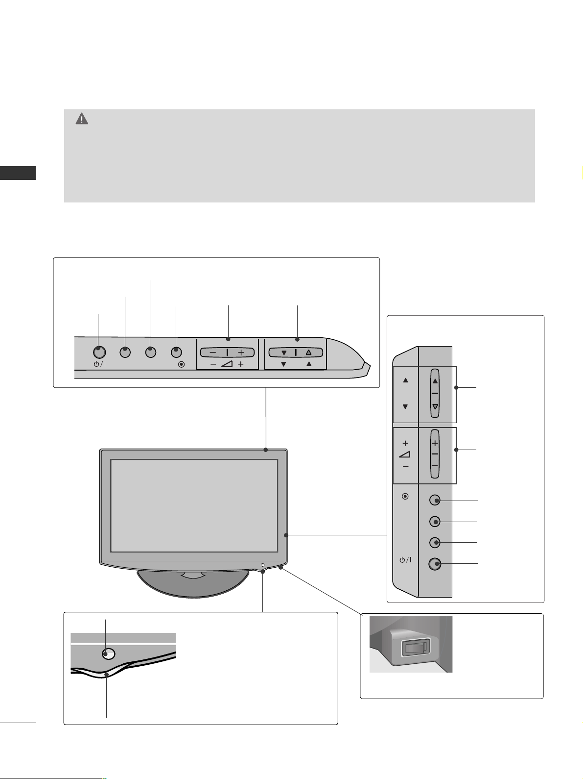
PREPARATION
PREPARATION
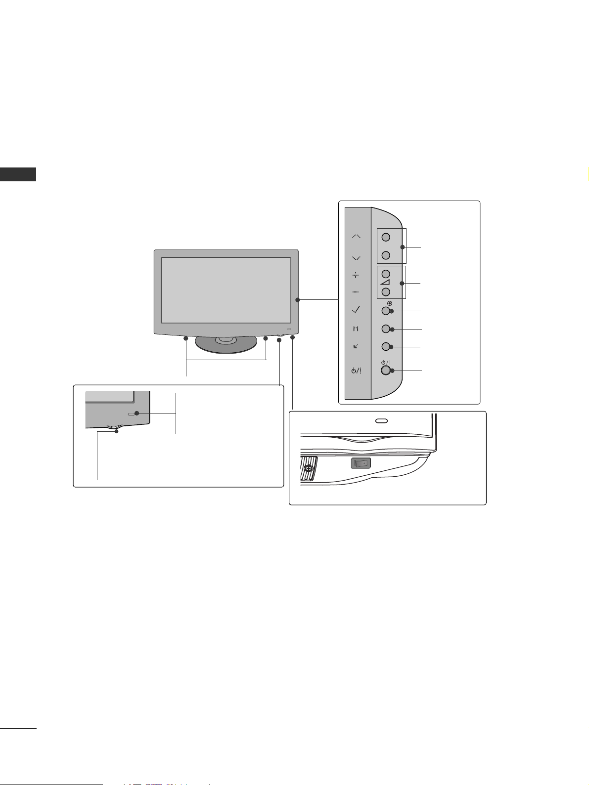
FRONT PANEL CONTROLS
■
Here shown may be somewhat different from your TV.
Only 32/37/42LH2***,
32/37/42LH3***
PROGRAMME
VOLUME
OK
Only 22/26LH2***
MENU
POWER
INPUT
INPUT
MENU
OK
P
PROGRAMME
VOLUME
OK
MENU
INPUT
POWER
Remote Control Sensor
Power/Standby Indicator
• Illuminates red in standby mode.
• Illuminates blue when the TV is switched on.
ON OFF
Only 22/26/32/37/42LH2***, 32/37/42LH3***
Main Power Switch
G
When the TV cannot be turned on with the remote control, press the main power button on the TV.
(When the power is turned off with the main power button on the TV, it will not be turned on with the
remote control).
G
Do not step on the glass stand or subject it to any impact.
It may break, causing possible injury from fragments of glass, or the TV may fall.
G
Do not drag the TV. The floor or the product may be damaged.
CAUTION
Except for 22LH2***
INPUT
MENU
OK
P
5
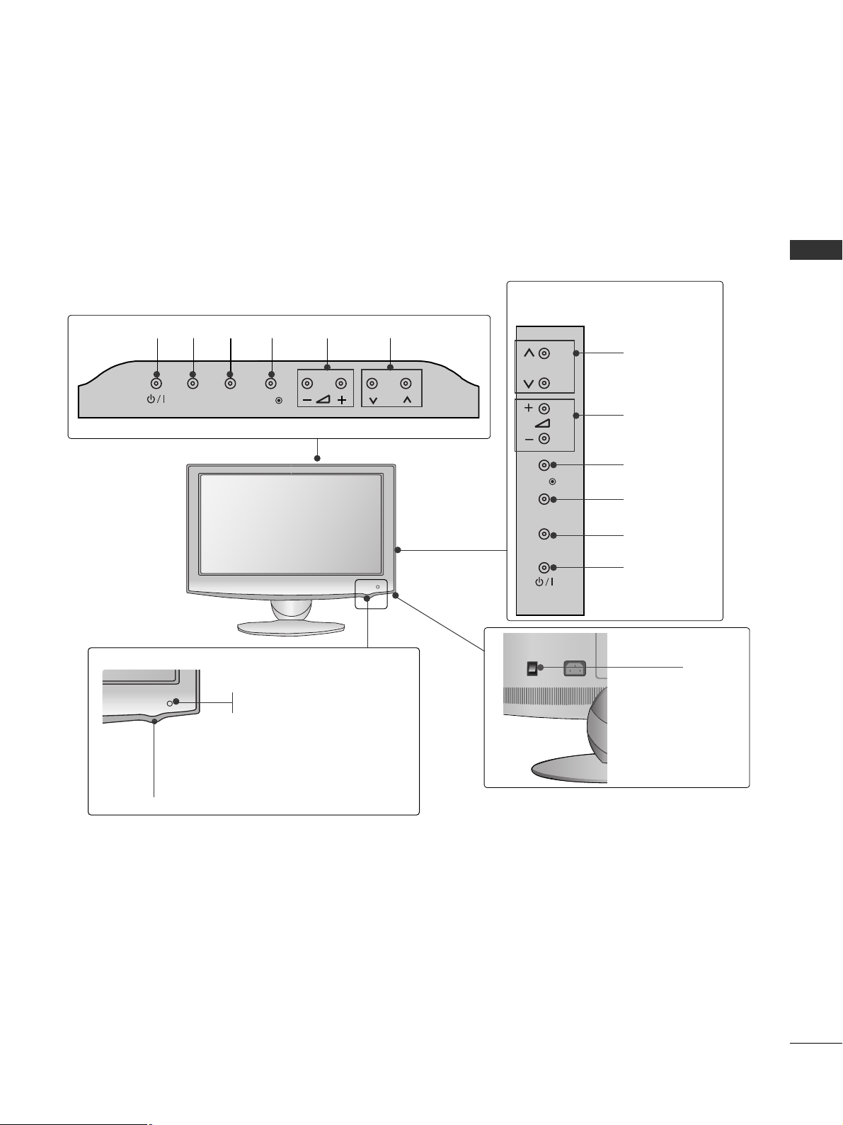
PREPARATION
Only 32/37/42/47/55LH5
***
PROGRAMME
VOLUME
OK
MENU
INPUT
POWER
P
Main Power Switch
Remote Control Sensor
Intelligent Sensor
Adjusts picture according to
the surrounding conditions.
Power/Standby Indicator
•
Illuminates red in standby mode.
•
Illuminates blue when the TV is switched on.
■
Here shown may be somewhat different from your TV.
MENU
INPUT
OFF ON
P
OK
6
PREPARATION
PREPARATION
Only 42/47LH9
***
PROGRAMME
VOLUME
OK
MENU
INPUT
POWER
P
Main Power Switch
Remote Control Sensor
Intelligent Sensor
Adjusts picture according to
the surrounding conditions.
Power/Standby Indicator
• Illuminates red in standby mode.
•
Illuminates blue when the TV is switched on.
SPEAKER
■
Here shown may be somewhat different from your TV.
P
OK
MENU
INPUT
OFF ON
7
PREPARATION
■
Here shown may be somewhat different from your TV.
Only 22/26LU5
***
P
PROGRAMME
VOLUME
OK
MENU
INPUT
POWER
Only 22LU5***
Only 26LU5***
VOLUME
POWER
INPUT MENU OK
PROGRAMME
Main
Power
Switch
ON
OFF
P
Remote Control Sensor
Power/Standby Indicator
Illuminates red in standby mode.
Illuminates white when the TV is switched on.
INPUT
MENU
OK
P
P
OK
MENU
INPUT
8
PREPARATION
PREPARATION
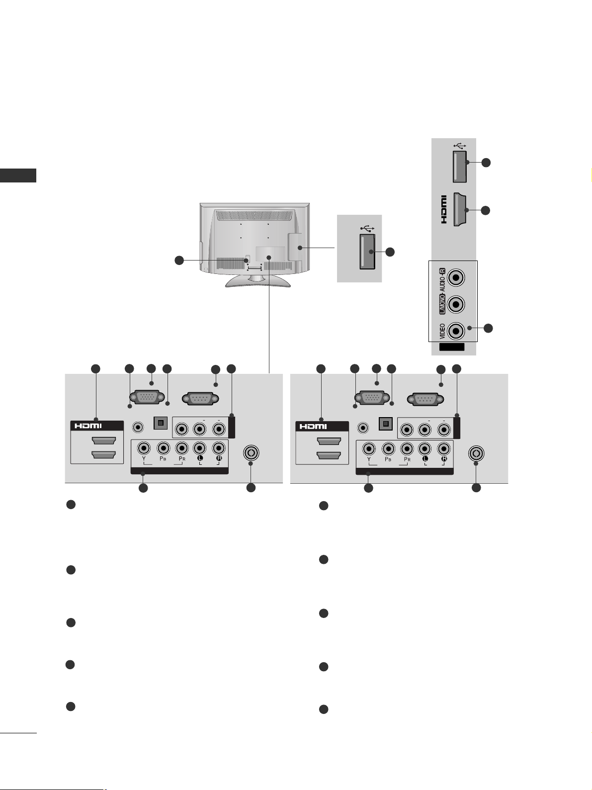
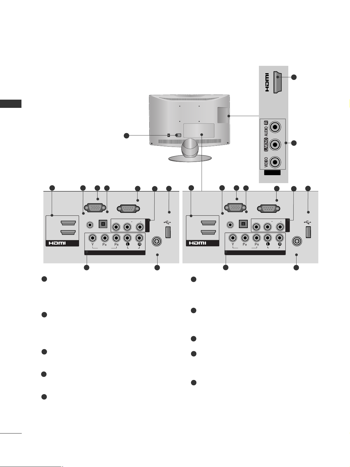
BACK PANEL INFORMATION
■
Here shown may be somewhat different from your TV.
Only 22/
26/32/37/42LH2
***
, 32/37/42LH3
***
Power Cord Socket
This TV operates on an AC power. The voltage is
indicated on the Specifications page. Never
attempt to operate the TV on DC power.
HDMI/DVI IN Input
Connect a HDMI signal to HDMI IN. Or DVI (VIDEO)
signal to HDMI/DVI port with DVI to HDMI cable.
RGB/DVI Audio Input
Connect the audio from a PC or DTV.
RGB Input
Connect the output from a PC.
OPTICAL DIGITAL AUDIO OUT
Connect digital audio to various types of equipment.
Connect to a Digital Audio Component.
Use an Optical audio cable.
RS-232C IN (CONTROL & SERVICE) PORT
Connect to the RS-232C port on a PC.
This port is used for Service or Hotel mode.
Audio/Video Input
Connect audio/video output from an external
device to these jacks.
Component Input
Connect a component video/audio device to
these jacks.
Antenna Input
Connect RF antenna to this jack.
SERVICE ONLY PORT
1
2
3
4
5
6
7
8
9
10
1
USB
SERVICE ONLY
USB
SERVICE ONLY
10
AV IN2
IN 3
USB
SERVICE ONLY
10
Only 22/
26/32/37/42LH2
*
**
Only
32/37/42LH3
*
**
2
7
Only 22/
26/32/37/42LH2
*
**
Only
32/37/42LH3
*
**
ANTENNA
IN
L/ MONO
R
AUDIO
VIDEO
USB
SERVICE ONLY
USB
SERVICE ONLY
ANTENNAANTENNA
IN
RGB IN
(PC)
RS-232C IN
(CONTROL&SERVICE)
AUDIO IN
(RGB/DVI)
COMPONENT IN
AUDIO
VIDEO
L/L/MONOMONO
R
AUDIOAUDIO
VIDEOVIDEO
AV IN
OPTICAL
DIGITAL
AUDIO OUT
1
(DVI)
2
/DVI IN
2
6
4
8
3
5 7
9
ANTENNAANTENNA
IN
RGB IN
(PC)
RS-232C IN
(CONTROL&SERVICE)
AUDIO IN
(RGB/DVI)
COMPONENT IN
AUDIO
VIDEO
L/L/MONOMONO
R
AUDIOAUDIO
VIDEOVIDEO
AV IN1
OPTICAL
DIGITAL
AUDIO OUT
1
(DVI)
2
/DVI IN
USB
SERVICE ONLY
USB
SERVICE ONLY
2
6
4
8
3
5 7
9
9
PREPARATION
Only
32/37/42/47/55LH5
***
, 42/47LH9
***
10
2
7
1
ANTENNA IN
RGB IN
(PC)
RS-232C IN
(CONTROL&SERVICE)
AUDIO IN
1
2
COMPONENT IN
AUDIO
VIDEO
1(DVI)
2
L/L/MONOMONO
R
AUDIOAUDIO
VIDEOVIDEO
AV IN1
/DVI IN
3
(RGB/DVI)
OPTICAL DIGITAL
AUDIO OUT
3
2
8
5
9
4
6
7
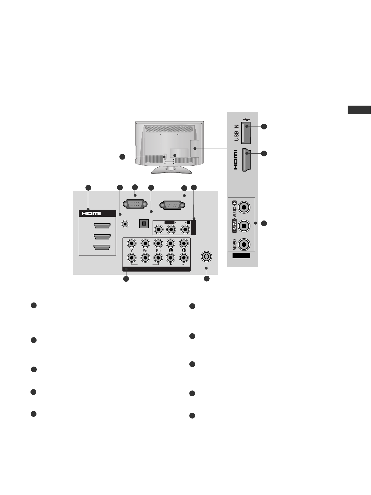
Power Cord Socket
This TV operates on an AC power. The voltage is
indicated on the Specifications page. Never
attempt to operate the TV on DC power.
HDMI/DVI IN Input
Connect a HDMI signal to HDMI IN. Or DVI (VIDEO)
signal to HDMI/DVI port with DVI to HDMI cable.
RGB/DVI Audio Input
Connect the audio from a PC or DTV.
RGB IN Input
Connect the output from a PC.
OPTICAL DIGITAL AUDIO OUT
Connect digital audio to various types of equipment.
Connect to a Digital Audio Component.
Use an Optical audio cable.
RS-232C IN (CONTROL & SERVICE) PORT
Connect to the RS-232C port on a PC.
This port is used for Service or Hotel mode.
Audio/Video Input
Connect audio/video output from an external
device to these jacks.
Component Input
Connect a component video/audio device to
these jacks.
Antenna Input
Connect RF antenna to this jack.
USB IN Input
Connect USB storage device to this jack.
1
2
3
4
5
6
7
8
9
10
■
Here shown may be somewhat different from your TV.
IN 4
AV IN2
10
PREPARATION
PREPARATION
Only 22/26LU5
***
2
7
■
Here shown may be somewhat different from your TV.
1
OOnn ll yy 2266 LL UU55 ** ** **
ANTENNA
IN
RGB IN
(PC)
RS-232C IN
(CONTROL&SERVICE)
AUDIO IN
(RGB/DVI)
1(DVI)
2
AV IN
OPTICAL
DIGITAL
AUDIO OUT
/DVI IN
COMPONENT IN
AUDIO
VIDEO
USB IN
SERVICE ONLY
L(L(MONO)MONO)
R
AUDIOAUDIO
VIDEOVIDEO
3
2
9
10
6
7
4
Power Cord Socket
This TV operates on an AC power. The voltage is
indicated on the Specifications page. Never
attempt to operate the TV on DC power.
HDMI Input
Connect an HDMI signal to HDMI IN.
Or DVI (VIDEO) signal to HDMI/DVI port with DVI
to HDMI cable.
RGB/DVI Audio Input
Connect the audio from a PC or DTV.
RGB IN Input
Connect the output from a PC.
OPTICAL DIGITAL AUDIO OUT
Connect digital audio from various types of equipment.
Note: In standby mode, these ports do not work.
RS-232C IN (CONTROL & SERVICE) PORT
Connect to the RS-232C port on a PC.
This port is used for Service or Hotel mode.
Audio/Video Input
Connect audio/video output from an external
device to these jacks.
SERVICE ONLY PORT
Component Input
Connect a component video/audio device to
these jacks.
Antenna Input
Connect RF antenna to this jack.
1
2
3
4
5
6
8
9
10
7
OOnn ll yy 2266 LL UU55 ** ** **
5
8
ANTENNA
IN
L( MONO)
R
AUDIO
VIDEO
ANTENNA
IN
RGB IN
(PC)
RS-232C IN
(CONTROL&SERVICE)
AUDIO IN
(RGB/DVI)
1(DVI)
2
AV IN1
OPTICAL
DIGITAL
AUDIO OUT
/DVI IN
COMPONENT IN
AUDIO
VIDEO
USB IN
SERVICE ONLY
L(L(MONO)MONO)
R
AUDIOAUDIO
VIDEOVIDEO
3
2
9
10
6
7
4
5
8
IN 3
ON
OFF
AV IN2
11
PREPARATION
STAND INSTALLATION
1
2
3
Carefully place the TV screen side down on a cushioned
surface to protect the screen from damage.
Assemble the TV as shown.
Fix the 4 bolts securely using the holes in the
back of the TV.
Only 26/32/37/42LH2
*
**
,
32/37/42LH3
*
**
, 32/37/42/47LH5
*
**,
42/47LH9***
■
Image shown may differ from your TV
When assembling the desk type stand, check whether the bolt is fully tightened. (If not tightened fully, the product can
tilt forward after the product installation.) If you tighten the bolt with excessive force, the bolt can deviate from abrasion of the tightening part of the bolt.
1
Carefully place the TV screen side down on a cushioned surface to protect the screen from damage.
2
Assemble the TV as shown.
Only 22LH2
***
Cover Base
Only 22/26LU5
***
1
2
Carefully place the TV screen side down on a cushioned surface to protect the screen from damage.
Fix the 2 or 3 bolts securely using the holes as
shown.
(Only 26LU5
***
)
12
PREPARATION
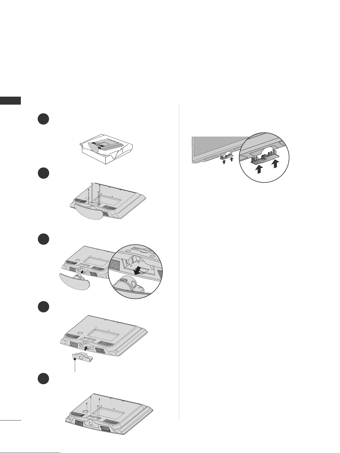
PREPARATION
Only 22LH2
***
■
Here shown may be somewhat different from your TV.
When installing the wall-mounted unit, use the protection cover.
NOT USING THE DESK-TYPE STAND
Loose the bolts from TV.
Insert the
PPrr oottee cc tt iioonn CC oo vv eerr
into the TV.
Detach the
SStt aa nndd BBoo dd yy
from
TT VV
.
Fix the 4 bolts securely using the holes in the
back of the TV.
2
3
4
1
Carefully place the TV screen side down on a cushioned surface to protect the screen from damage.
5
Protection Cover
Only 26/32/37/42LH2***,
32/37/42LH3***,
32/37/42/47/55LH5
***, 42/47LH9***
Insert the
PPRROOTTEECCTTII OONN CCOOVVEERR
into the TV
until clicking sound.
13
PREPARATION
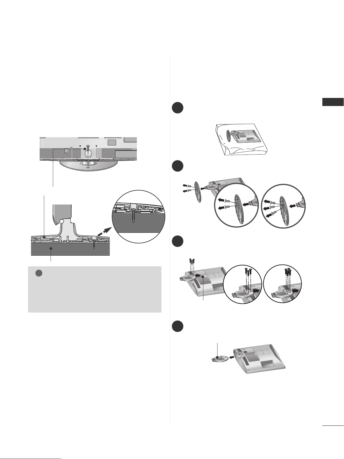
ATTACHING THE TV TO A DESK
(Only 26/32/37/42LH2***,
32/37/42LH3***, 26LU5***,
32/37/42LH5***, 42LH9***)
■
Here shown may differ from your TV.
The TV must be attached to desk so it cannot be
pulled in a forward/backward direction, potentially
causing injury or damaging the product. Use only an
attached screw.
1-Screw
(provided as parts of the product)
Desk
Stand
WARNING
!
G
To prevent TV from falling over, the TV should
be securely attached to the floor/wall per
installation instructions. Tipping, shaking, or
rocking the machine may cause injury.
2
Loose the bolts and then detach the stand from
TV.
3
Loose the bolts and then detach the
CC oo vvee rr
BBaass ee
from
TT VV
.
4
Detach the
SStt aa nndd BBoo dd yy
from
TT VV
.
Stand Body
DETACHING STAND
1
Carefully place the TV screen side down on a cushioned surface to protect the screen from damage.
Cover Base
Only 22/26LU5
***
(Only 26LU5
***
)
■
Here shown may be somewhat different from your TV.
(Only 26LU5
***
)
14
PREPARATION
PREPARATION
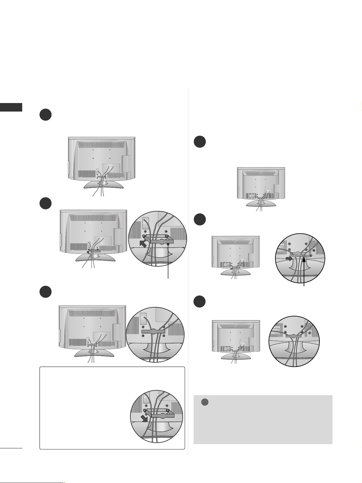
BACK COVER FOR WIRE ARRANGEMENT
■
Here shown may be somewhat different from your TV.
Connect the cables as necessary.
To connect additional equipment, see the
EXTERNAL EQUIPMENT SETUP section.
Fit the CABLE MANAGEMENT CLIP as shown.
Only 22LH2
***
How to remove the CABLE MANAGEMENT CLIP(
Only 22LH2
***
)
GG
Hold the CABLE MANAGEMENT CLIP with both hands
and pull it backward.
CABLE MANAGEMENT CLIP
Connect the cables as necessary.
To connect additional equipment, see the
External Equipment Setup section of the manual.
1
Open the
CC AABBLLEE MMAANN AAGGEE MMEENN TT CC LL IIPP
as
shown and manage the cables.
2
CABLE MANAGEMENT CLIP
Fit the
CC AABBLLEE MMAANN AAGGEE MMEENN TT CC LL IIPP
as
shown.
3
Only 26/32/37/42LH2***,
32/37/42LH3***,
32/37/42/47/55LH5
***,
42/47LH9***
1
Install the CABLE MANAGEMENT CLIP as shown.
2
3
NOTE
!
GG
Do not use the CABLE MANAGEMENT CLIP
to lift the TV.
- If the TV is dropped, you may be injured or
the TV may be damaged.
15
PREPARATION
CAREFUL INSTALLATION ADVICE
A
You should purchase necessary components to fix the TV
safety and secure to the wall on the market.
A
Position the TV close to the wall to avoid the possibility
of it falling when pushed.
A
The instructions shown below are a safer way to set up
the TV, by fixing it to the wall, avoiding the possibility of
it falling forwards if pulled. This will prevent the TV from
falling forward and causing injury. This will also prevent
the TV from damage. Ensure that children do not climb
or hang from the TV.
NOTE
!
G
When moving the TV undo the cords first.
G
Use a platform or cabinet strong and large enough
to support the size and weight of the TV.
G
To use the TV safely make sure that the height of the
bracket on the wall and on the TV is the same.
3
1
2
Use the eye-bolts or TV brackets/bolts to fix the
product to the wall as shown in the picture.
(If your TV has bolts in the eyebolts, loosen then
bolts.)
* Insert the eye-bolts or TV brackets/bolts and tight-
en them securely in the upper holes.
Secure the wall brackets with the bolts on the wall.
Match the height of the bracket that is mounted on
the wall.
3
Use a sturdy rope to tie the product for alignmen. It
is safer to tie the rope so it becomes horizontal
between the wall and the product.
2
1
2
1
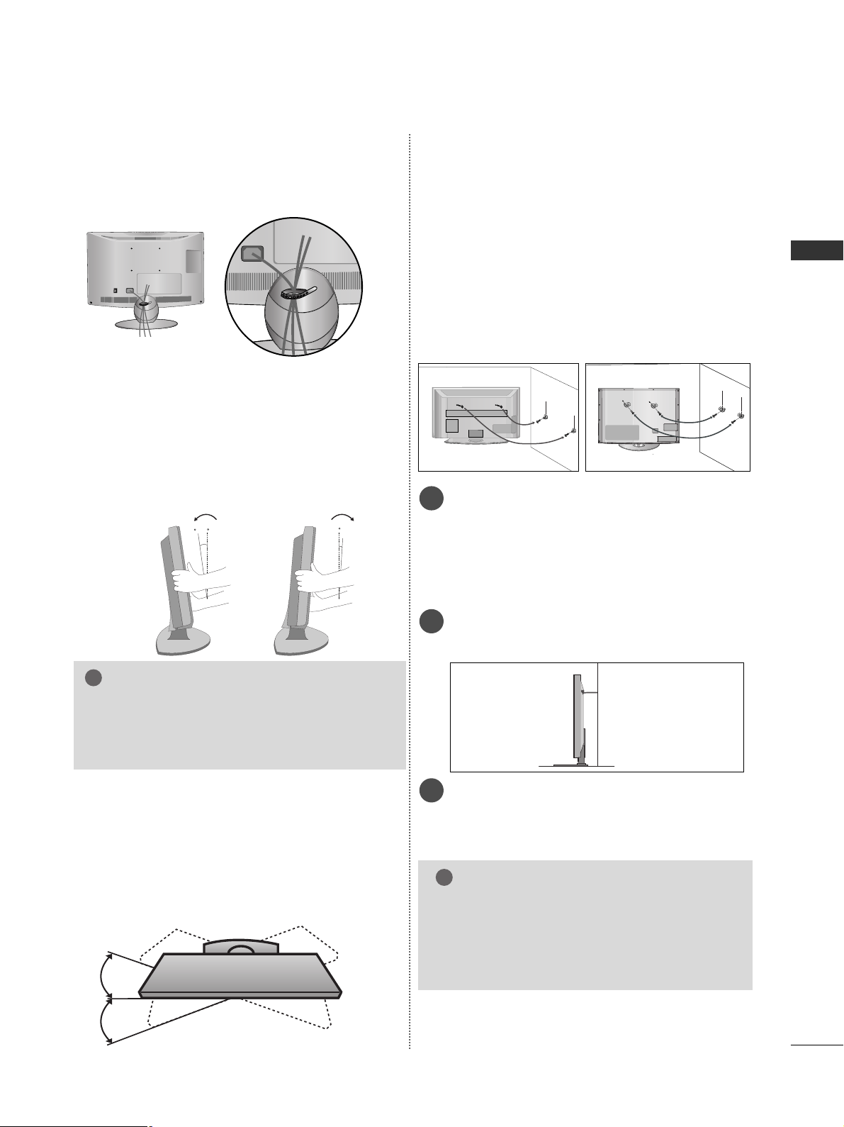
POSITIONING YOUR DISPLAY
(Only 22LH2
***
)
■
Here shown may be somewhat different from your TV.
■
Adjust the position of the panel in various ways for
maximum comfort.
• Tilt range
12
0
3
0
SWIVEL STAND
(Except for 22/26LU5***,
22LH2***
)
After installing the TV, you can adjust the TV set
manually to the left or right direction by 20 degrees
to suit your viewing position.
Only 22/26LU5
***
After Connecting the cables as necessary, install
CABLE HOLDER as shown and bundle the cables.
NOTE
!
G
The following model is a fixed stand type
model without the Tilt and Swivel features so
excessive pressure may damage the set.
- 22/26LU5***
16
PREPARATION
PREPARATION
4 inches
4 inches
4 inches
4 inches
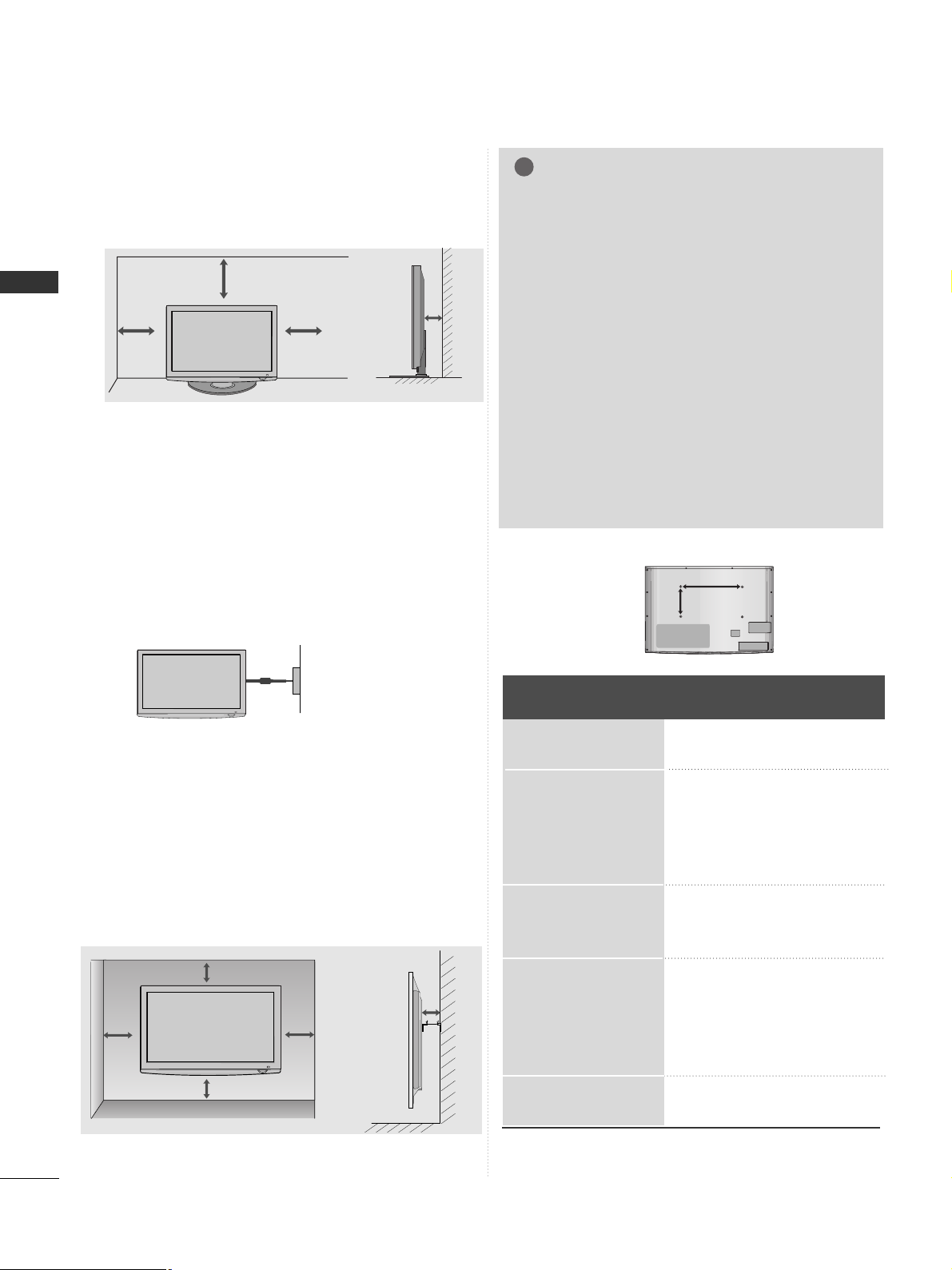
DESKTOP PEDESTAL INSTALLATION
For adequate ventilation allow a clearance of 4”
(10cm) all around the TV.
A
The TV can be installed in various ways such as on a
wall, or on a desktop etc.
A
The TV is designed to be mounted horizontally.
Power Supply
Circuit breaker
EARTHING
Ensure that you connect the earth wire to prevent
possible electric shock. If grounding methods are not
possible, have a qualified electrician install a separate
circuit breaker.
Do not try to earth the TV by connecting it to telephone wires, lightening rods or gas pipes.
WALL MOUNT: HORIZONTAL INSTALLATION
A
We recommend the use of a LG Brand wall mounting
bracket when mounting the TV to a wall.
A
We recommend that you purchase a wall mounting
bracket which supports VESA standard.
A
LG recommends that wall mounting be performed by a
qualified professional installer.
NOTE
!
G Should Install wall mount on a solid wall perpendicular to
the floor.
G Should use a special wall mount, if you want to install it to
ceiling or slanted wall.
G The surface that wall mount is to be mounted on should
be of sufficient strength to support the weight of TV set;
e.g. concrete, natural rock, brick and hollow block.
G Installing screw type and length depends on the wall
mount used. Further information, refer to the instructions
included with the mount.
G LG is not liable for any accidents or damage to property or
TV due to incorrect installation:
- Where a non-compliant VESA wall mount is used.
- Incorrect fastening of screws to surface which may cause
TV to fall and cause personal injury.
- Not following the recommended Installation method.
4 inches
4 inches
4 inches
4 inches
4 inches
AA
BB
Model
VESA
(A *B)
Standard
Screw
Quantity
22LU5***
26LU5***
22LH2***
26LH2***
32LH2***
37LH2***
42LH2***
32LH3***
37LH3***
42LH3***
32LH5***
37LH5***
42LH5***
47LH5***
55LH5***
42LH9***
47LH9***
100 * 10 0
200 * 10 0
100 * 10 0
200 * 10 0
200 * 10 0
200 * 200
200 * 200
200 * 10 0
200 * 200
200 * 200
200 * 10 0
200 * 200
200 * 200
200 * 200
400 * 400
200 * 200
200 * 200
M4
M4
M4
M4
M4
M6
M6
M4
M6
M6
M4
M6
M6
M6
M6
M6
M6
4
4
4
4
4
4
4
4
4
4
4
4
4
4
4
4
4
17
PREPARATION
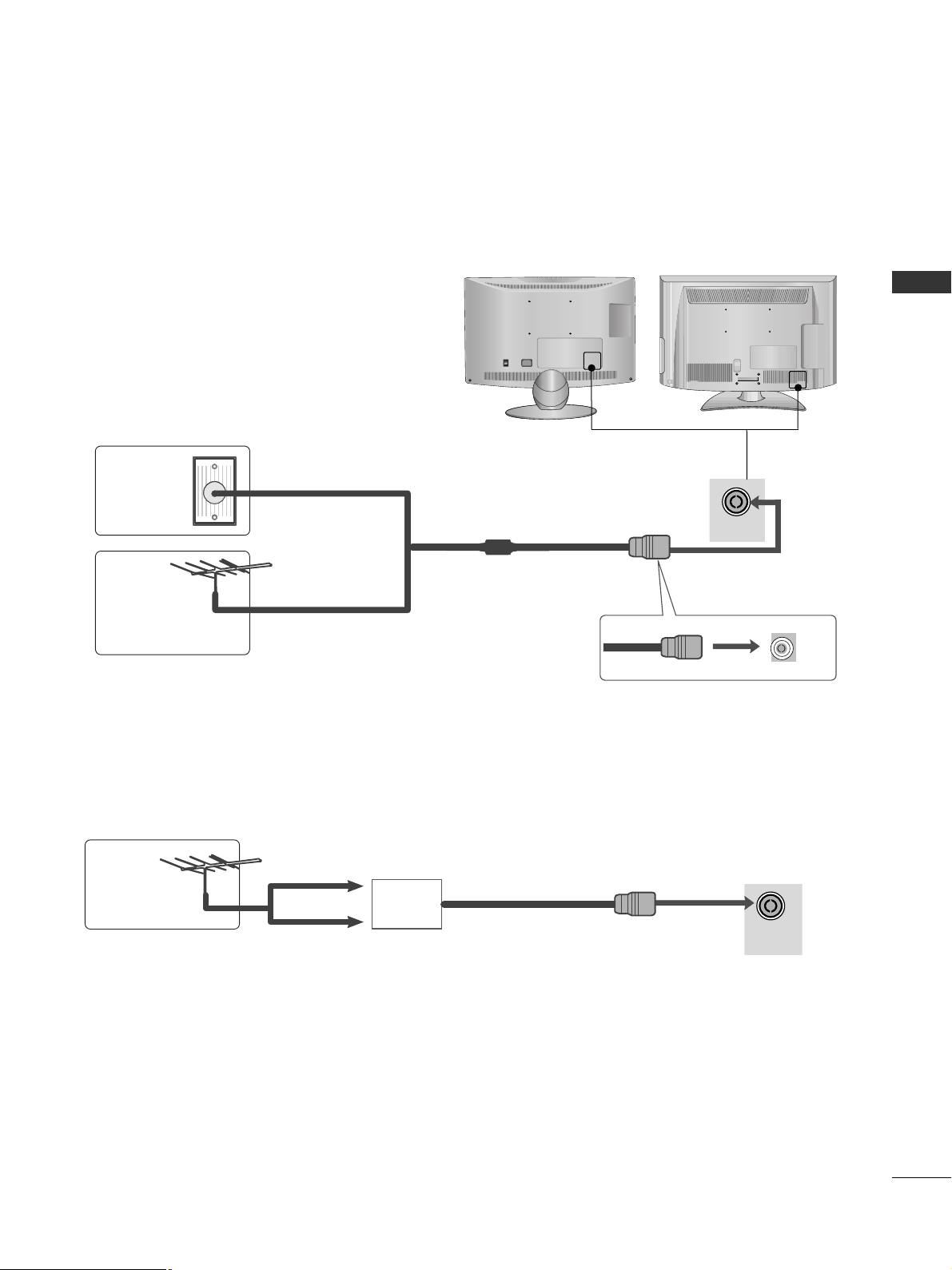
ANTENNA IN
ANTENNA IN
ANTENNA CONNECTION
■
For optimum picture quality, adjust antenna direction.
■
An antenna cable and converter are not supplied.
■
To prevent damage do not connect to the mains outlet until all connections are made between the devices.
Multi-family Dwellings/Apartments
(Connect to wall antenna socket)
Single-family Dwellings /Houses
(Connect to wall jack for outdoor antenna)
Outdoor
Antenna
(VHF, UHF)
Wall
Antenna
Socket
RF Coaxial Wire (75 ohm)
Antenna
UHF
Signal
Amplifier
VHF
■
In poor signal areas, to achieve better picture quality it may be necessary to install a signal amplifier to the
antenna as shown above.
■
If signal needs to be split for two TVs, use an antenna signal splitter for connection.
ON
OFF
18
EXTERNAL EQUIPMENT SETUP
EXTERNAL EQUIPMENT SETUP
HD RECEIVER SETUP
■
To avoid damaging any equipment, never plug in any power cords until you have finished connecting all equipment.
■
This section on EXTERNAL EQUIPMENT SETUP mainly uses diagrams for the 32/37/42/47/55LH5
***
models.
■
Here shown may differ from your TV.
Connecting with a component cable
1
2
COMPONENT IN
AUDIO
VIDEO
1
2
Signal
480i/576i
480p/576p
720p/1080i
10 8 0 p
Component
O
O
O
O
(50Hz/60Hz)
HDMI
X
O
O
O
(24Hz/30Hz/50Hz/60Hz)
■
This TV can receive Digital RF/Cable signals without an external digital set-top box. However, if you do receive
Digital signals from a digital set-top box or other digital external device, refer to the diagram as shown below.
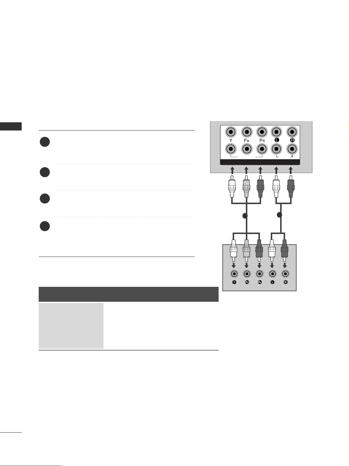
Connect the video outputs (Y, PB, PR
)
of the digital set
top box to the
CC OOMMPPOONNEE NNTT IINN VV IIDDEE OO
jacks on the
TV.
Connect the audio output of the digital set-top box to
the
CC OOMMPPOONN EE NNTT IINN AAUUDDIIOO
jacks on the TV.
Turn on the digital set-top box.
(
Refer to the owner’s manual for the digital set-top box.
)
Select
CC oo mm ppoonnee nntt 11
input source using the
IINN PP UU TT
button on the remote control.
If connected to
CC OOMMPPOONN EENNTT IINN 22
, select
CC oo mmppoonnee nn tt 22
input source.
2
3
4
1
GG
HDMI Audio Supported format : Dolby Digital, PCM
19
EXTERNAL EQUIPMENT SETUP
COMPON
VIDEO
YP
BPR
1
2
OPTICA
AUDIO
AUDIO IN
(RGB/DVI)
1(DVI)
2
/DVI IN
3
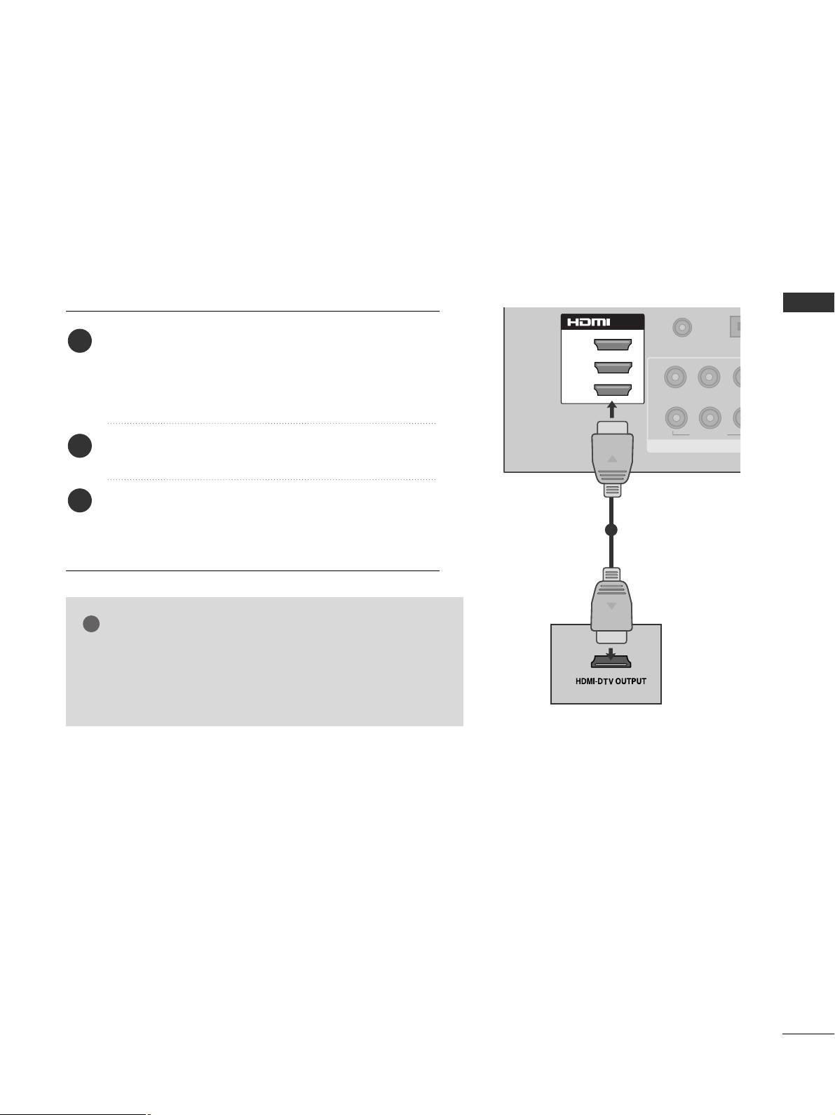
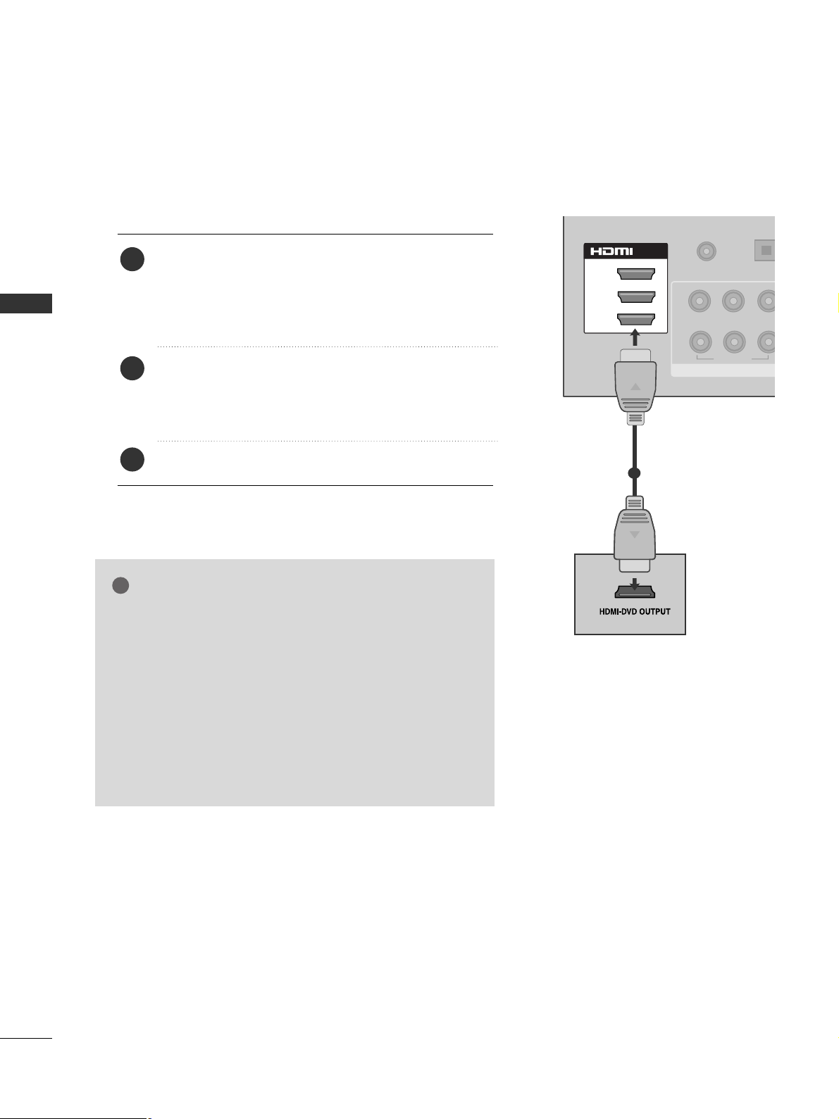
Connecting a set-top box with an HDMI cable
1
Connect the digital set-top box to
HHDDMMII//DD VVII IINN 11
,
HHDDMMII IINN 22,, HH DDMMII IINN 33
(Except for
22/26/32/37/42LH2***, 22LU5***) or
HHDDMMII IINN 44
(Only 32/37/42/47/55LH5
***, 42/47LH9***
) jack on the
TV.
Turn on the digital set-top box.
(
Refer to the owner’s manual for the digital set-top box.
)
Select
HH DD MMII 11, HH DD MMII 22, HH DD MMII 33
(Except for
22/26/32/37/42LH2***, 22LU5***) or
HH DD MMII 44
(Only
32/37/42/47/55LH5
***, 42/47LH9***
) input source
using the
IINN PP UU TT
button on the remote control.
2
3
1
GG
Check that your HDMI cable is version 1.3 or higher.
If the HDMI cables don’t support HDMI version 1.3, flickering or no screen display can result. Please use the latest
cables that support at least HDMI version 1.3.
NOTE
!
20
EXTERNAL EQUIPMENT SETUP
EXTERNAL EQUIPMENT SETUP
EXTERNAL EQUIPMENT SETUP
COMPONEN
VIDEO
YP
BPR
1
2
OPTICAL DIG
AUDIO OU
AUDIO IN
1(DVI)
3
/DVI IN
(RGB/DVI)
2
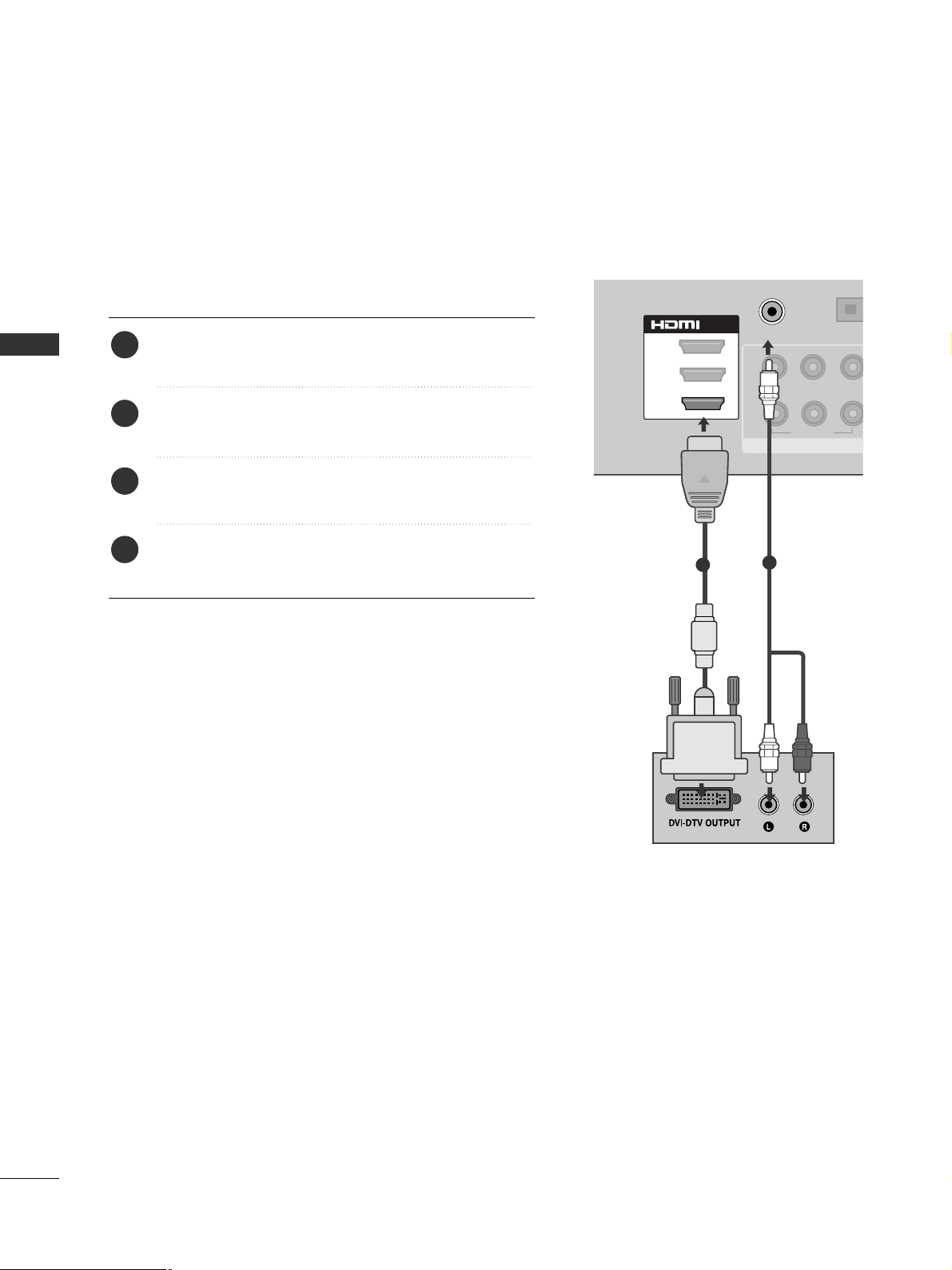
Connecting with an HDMI to DVI cable
1
2
Connect the digital set-top box to
HHDDMMII//DDVVII IINN 11
jack on the TV.
Connect the audio output of the digital set-top box to
the
AAUU DDIIOO II NN (( RRGGBB//DDVV II ))
jack on the TV.
Turn on the digital set-top box. (Refer to the owner’s
manual for the digital set-top box.
)
Select
HH DD MMII 11
input source using the
IINNPP UUTT
button
on the remote control.
2
3
4
1
21
EXTERNAL EQUIPMENT SETUP
DVD SETUP
Connecting with a component cable
1
2
COMPONENT IN
AUDIO
VIDEO
L/MONO
R
AUDIO
VIDEO
Component Input ports
To achieve better picture quality, connect a DVD player to
the component input ports as shown below.
Component ports on the TV
YPB PR
Video output ports
on DVD player
Y
Y
Y
Y
P
B
B-Y
Cb
Pb
P
R
R-Y
Cr
Pr
1
2
Connect the video outputs (Y, PB, PR
)
of the DVD to
the
CC OOMMPPOONNEE NNTT IINN VV II DDEE OO
jacks on the TV.
Connect the audio outputs of the DVD to the
CC OOMMPPOONN EE NNTT IINN AAUUDDIIOO
jacks on the TV.
Turn on the DVD player, insert a DVD.
Select
CC oo mmppoonnee nn tt 11
input source using the
IINNPP UUTT
button on the remote control.
If connected to
CC OOMMPPOONN EENNTT IINN 22
, select
CC oo mmppoonnee nn tt 22
input source.
Refer to the DVD player's manual for operating instructions.
2
3
4
5
1
22
EXTERNAL EQUIPMENT SETUP
EXTERNAL EQUIPMENT SETUP
L/MONO
R
AUDIO
VIDEO
Connecting the HDMI cable
Connect the HDMI output of the DVD to the
HHDDMMII//DD VVII IINN 11,HHDDMMII IINN 22,, HH DDMMII IINN 33
(Except
for 22/26/32/37/42LH2***, 22LU5***) or
HHDDMMII IINN 44
(Only 32/37/42/47/55LH5
***, 42/47LH9***
)
jack on the
TV.
Select
HH DD MMII 11, HH DD MMII 22, HH DD MMII 33
(Except for
22/26/32/37/42LH2***, 22LU5***) or
HH DD MMII 44
(Only
32/37/42/47/55LH5
***, 42/47LH9***
)
input source
using the
IINN PP UU TT
button on the remote control.
Refer to the DVD player's manual for operating instructions.
2
3
1
1
GG
The TV can receive video and audio signals simultaneously
when using an HDMI cable.
GG
If the DVD does not support Auto HDMI, you must set the
output resolution appropriately.
GG
The TV set can process audio format of PCM or AC3, when
connect the external equipment using an HDMI cable.
GG
Check that your HDMI cable is version 1.3 or higher.
If the HDMI cables don’t support HDMI version 1.3, flickering or no screen display can result. Please use the latest
cables that support at least HDMI version 1.3.
NOTE
!
3
2
1(DVI)
/DVI IN
AUDIO IN
(RGB/DVI)
2
1
OPTICAL D
BPR
YP
VIDEO
COMPONE
AUDIO O
23
EXTERNAL EQUIPMENT SETUP
VCR SETUP
■
To avoid picture noise (interference), allow adequate distance between the VCR and TV.
LP
R
R
AUDIO
ANTENNA IN
OUTPUT
SWITCH
ANT IN
R
S-VIDEO VIDEO
ANT OUT
L
Wall Jack
Antenna
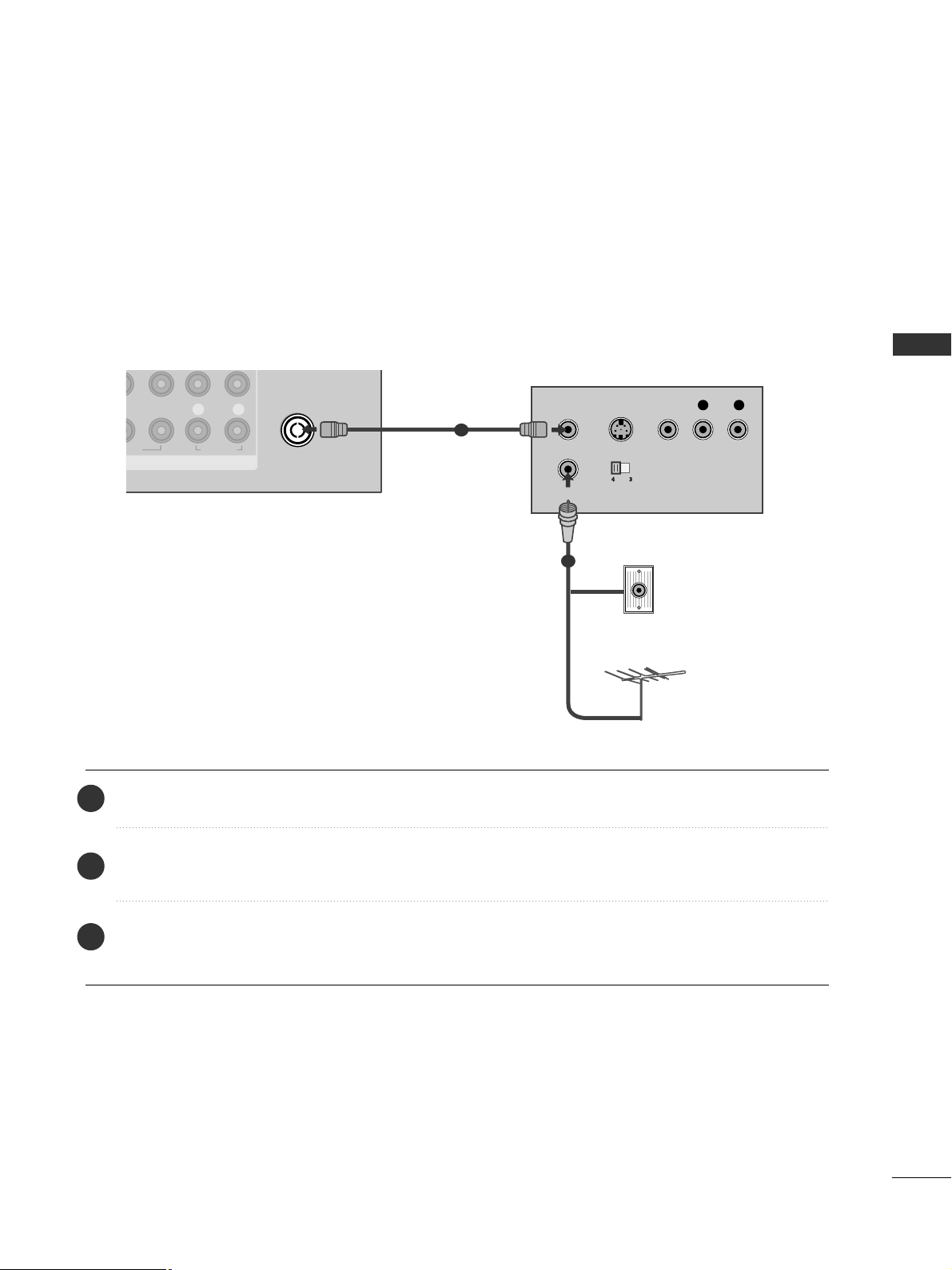
1
2
Connecting with a RF Cable
Connect the
AANNTT OOUUTT
socket of the VCR to the
AANNTT EENN NNAA II NN
socket on the TV.
Connect the antenna cable to the
AANN TT II NN
socket of the VCR.
Press the
PPLLAA YY
button on the VCR and match the appropriate channel between the TV and VCR for
viewing.
2
3
1
24
EXTERNAL EQUIPMENT SETUP
EXTERNAL EQUIPMENT SETUP
EXTERNAL EQUIPMENT SETUP
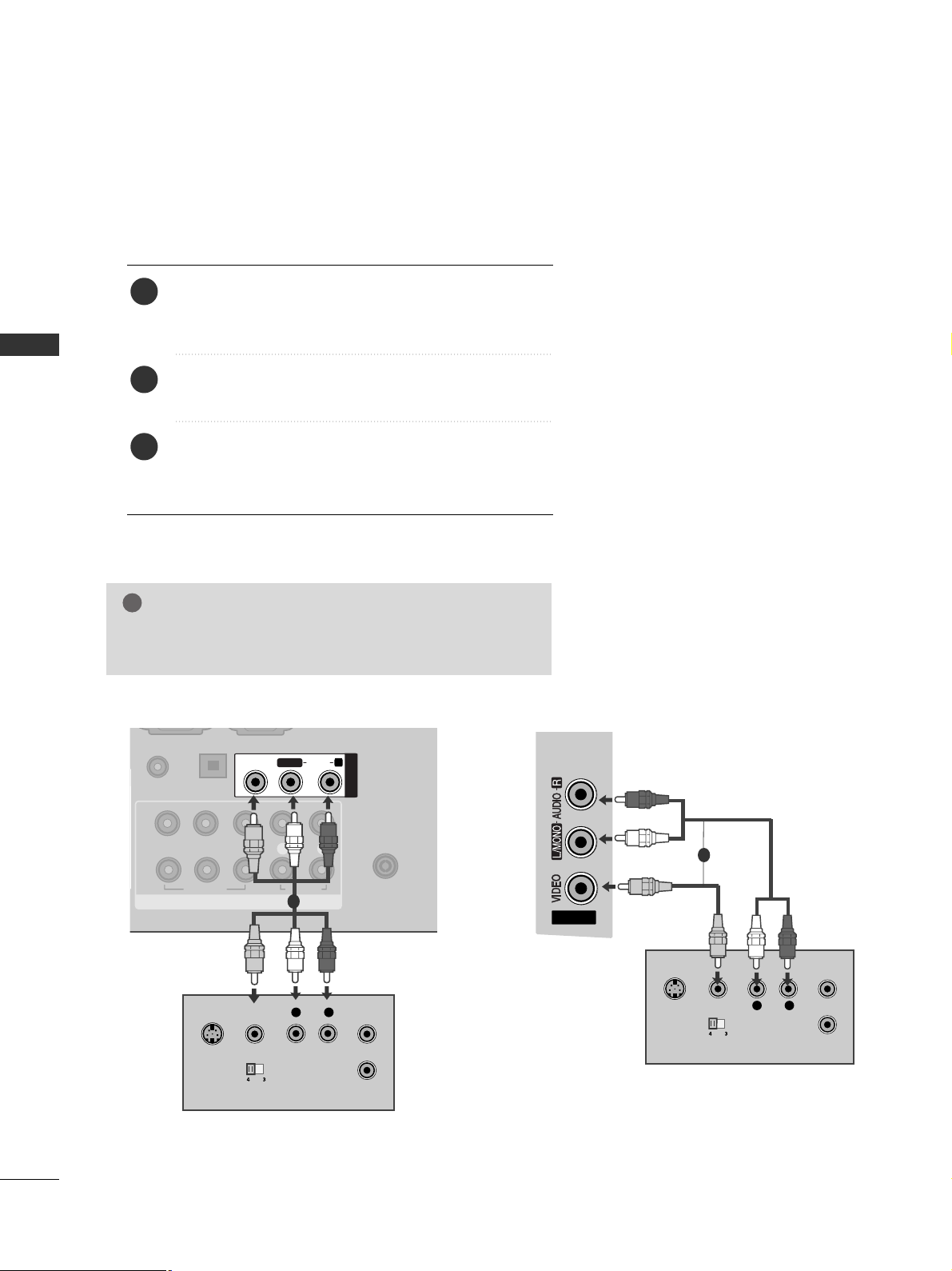
Connecting with a RCA cable
Connect the
AAUU DD IIOO/VVII DDEE OO
jacks between TV and
VCR. Match the jack colours (Video = yellow, Audio Left
= white, and Audio Right = red)
Insert a video tape into the VCR and press PLAY on
the VCR. (Refer to the VCR owner’s manual.
)
Select
AA VV 11
input source using the
IINN PP UU TT
button on
the remote control.
If connected to
AAVV 22
input, select
AAVV 22
input source.
1
2
3
GG
If you have a mono VCR, connect the audio cable from the
VCR to the
AAUU DDII OO LL// MMOONN OO
jack of the TV.
NOTE
!
AV IN 2V IN 2
L
R
S-VIDEO
VIDEO
OUTPUT
SWITCH
ANT IN
ANT OUT
1
AV IN 2
COMPONENT IN
VIDEO
LYP
BPR
R
AUDIO
ANTENNA IN
1
2
OPTICAL DIGITAL
AUDIO OUT
AUDIO IN
(RGB/DVI)
L/L/MONOMONO
R
AUDIOAUDIO
VIDEOVIDEO
AV IN1
VIDEO
OUTPUT
SWITCH
ANT IN
ANT OUT
L R
S-VIDEO
1
or
25
EXTERNAL EQUIPMENT SETUP
G
Do not look into the optical output port. Looking at the
laser beam may damage your vision.
CAUTION
AV IN 1
AUDIO IN
COMPONENT IN
VIDEO
LYP
BPR
R
AUDIO
VIDEO
AUDIO
/MONO
ANTE
1
2
OPTICAL DIGITAL
AUDIO OUT
(RGB/DVI)
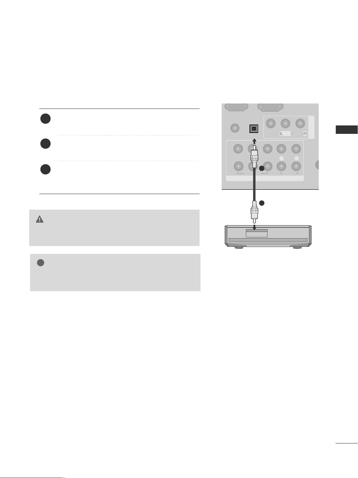
Connect one end of an optical cable to the TV Digital
Audio (Optical)Output port.
Connect the other end of the optical cable to the digital audio (Optical)input on the audio equipment.
Set the “TV Speaker option - Off ” in the AUDIO
menu.(
G
pp..110088
) Refer to the external audio equipment
instruction manual for operation.
2
3
1
1
2
DIGITAL AUDIO OUT SETUP
Sending the TV’s audio signal to external audio equipment via the Digital Audio Output (Optical) port.
If you want to enjoy digital broadcasting through 5.1-channel speakers, connect the OPTICAL DIGITAL
AUDIO OUT terminal on the back of TV to a Home Theater (or amp).
GG
When connecting with external audio equipments, such as
amplifiers or speakers, please turn the TV speakers off.
NOTE
!
26
EXTERNAL EQUIPMENT SETUP
EXTERNAL EQUIPMENT SETUP
EXTERNAL EQUIPMENT SETUP
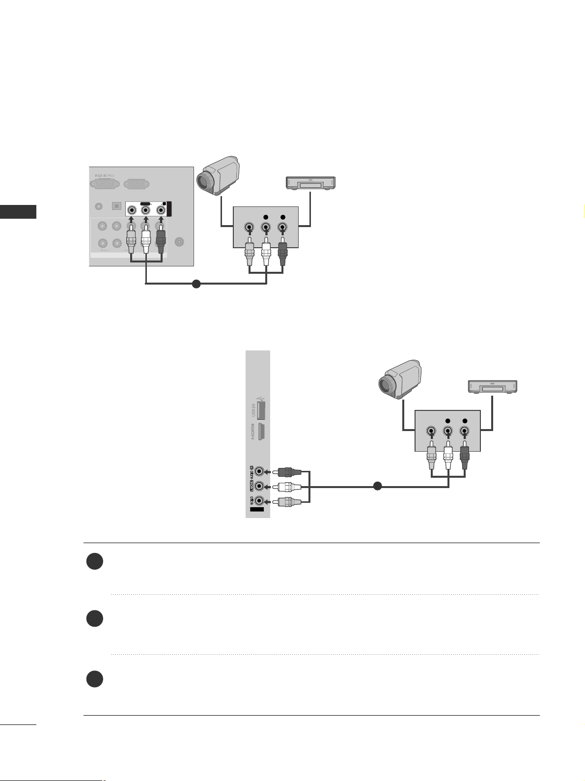
OTHER A/V SOURCE SETUP
Connect the
AAUU DD II OO/VVII DDEE OO
jacks between TV and external equipment. Match the jack colours
.
(
Video = yellow, Audio Left = white, and Audio Right = red
)
Select
AA VV11
input source with using the
IINNPP UUTT
button on the remote control.
If connected to
AAVV 22
input, select
AAVV 22
input source.
Operate the corresponding external equipment.
Refer to external equipment operating guide.
AV IN2
L R
VIDEO
IN 4
Camcorder
Video Game Set
1
1
2
3
RS-232C IN
(CONTROL & SERVICE)
COMPONENT IN
VIDEO
LYP
BPR
R
AUDIO
ANTENNA IN
1
2
OPTICAL DIGITAL
AUDIO OUT
AUDIO IN
(RGB/DVI)
L/MONO
R
AUDIOAUDIO
VIDEOVIDEO
AV IN1
L R
VIDEO
Camcorder
Video Game Set
1
or
27
EXTERNAL EQUIPMENT SETUP
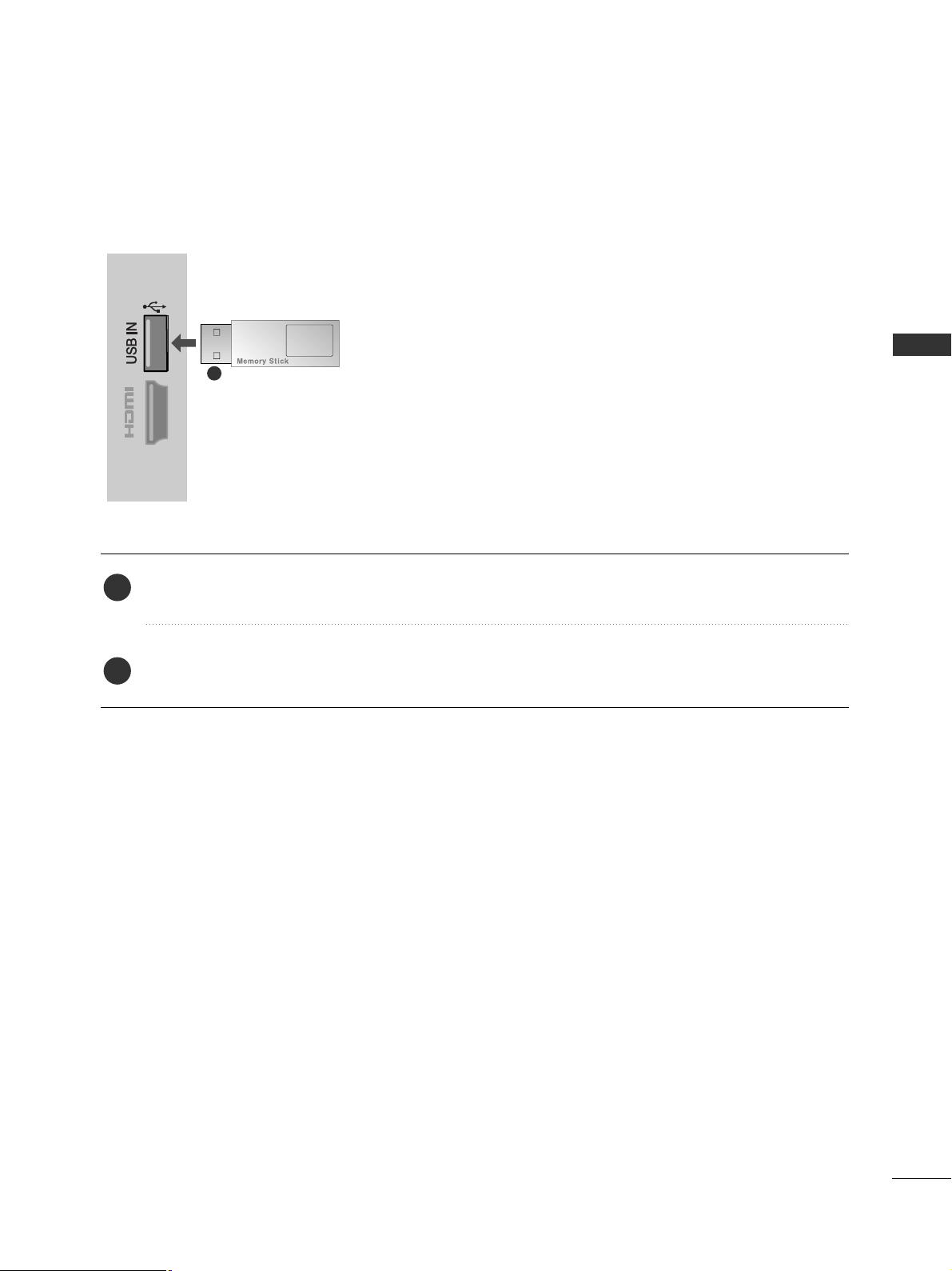
USB SETUP
(Except for 22/26/32/37/42LH2***, 32/37/42LH3***, 22/26LU5***)
IN 4
Connect the USB device to the
UUSSBB II NN
jacks on the TV.
After connecting the
UUSSBB IINN
jacks, you use the
UU SSBB
function. (
GG
pp..7700
)
2
1
1
28
EXTERNAL EQUIPMENT SETUP
EXTERNAL EQUIPMENT SETUP
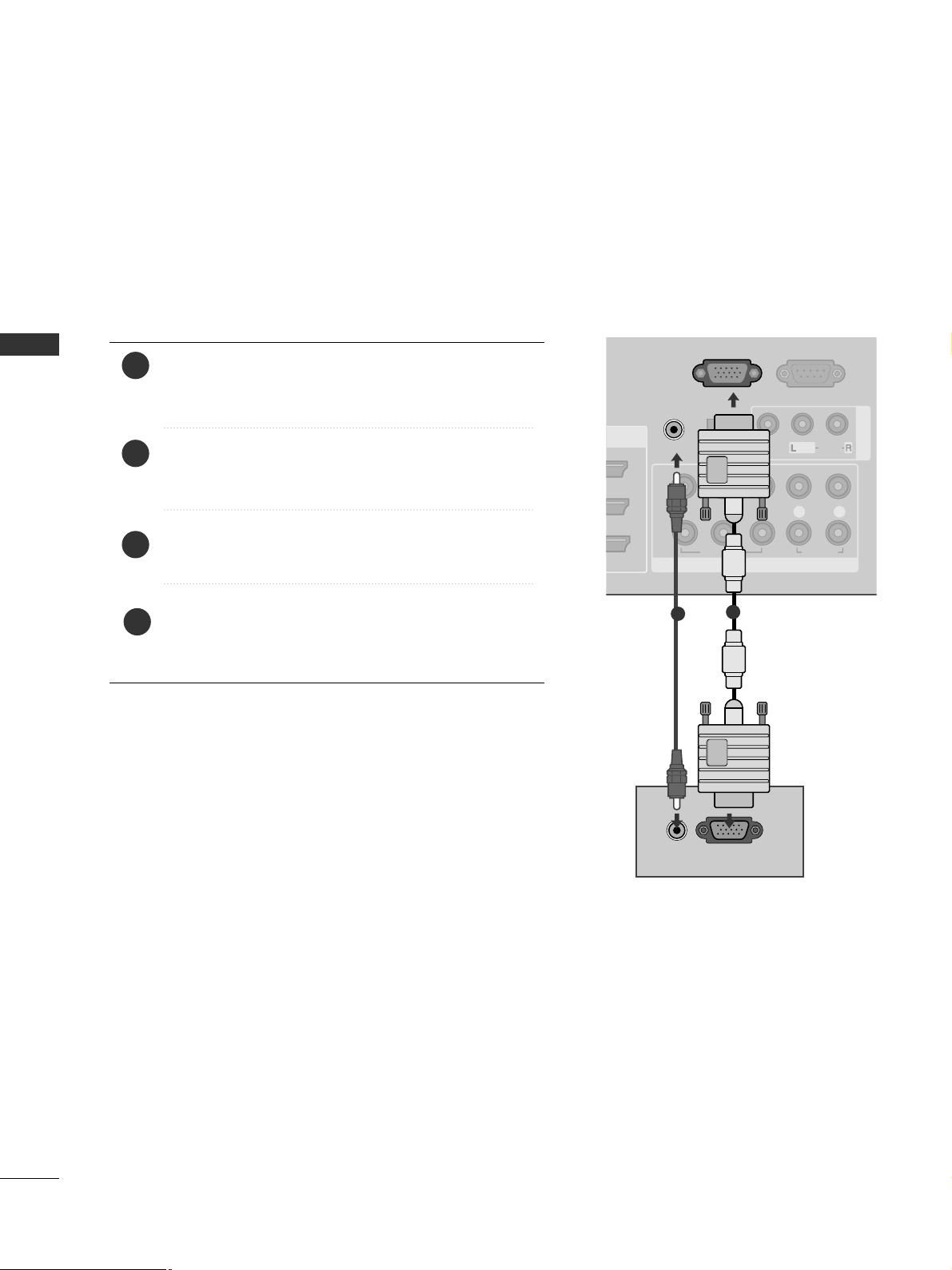
PC SETUP
This TV provides Plug and Play capability, meaning that the PC adjusts automatically to the TV's settings.
Connecting with a D-sub 15 pin cable
RS-232C IN
(CONTROL & SERVICE)
AV IN 1
COMPONENT IN
VIDEO
LYP
BPR
R
AUDIO
VIDEO
AUDIO
/MONO
A
1
2
OPTICAL DIGITAL
AUDIO OUT
RGB IN
(PC)
AUDIO IN
(RGB/DVI)
RGB OUTPUT
AUDIO
1
2
4
Connect the RGB output of the PC to the
RRGGBB IINN
(( PPCC))
jack on the TV.
Connect the PC audio output to the
AAUU DDII OO IINN
((RRGGBB// DDVV II))
jack on the TV.
Turn on the PC and the TV.
Select
RRGGBB
input source using the INPUT button on
the remote control.
2
3
1
 Loading...