

LG 37LB1D Owner’s Manual
LCD TV
Trademark of the DVB Digital Video
Broadcasting Project (1991 to 1996)
32LB1D
37 LB 1 D
42LB1D
32LB1DB
37 LB 1 DB
42LB1DB
Please read Information Manual included together
before reading this manual and operating your set.
ID Numbers 4096 : 32LB1D
4097 : 37LB1D
4095 : 42LB1D
4298 : 32LB1DB
4299 : 37LB1DB
4297 : 42LB1DB
P/NO : 38289U1004A (0608-REV02)
Printed in Korea

Owner's Manual
1.5V 1.5V
l/ll
TIME
INDEX
REVEAL
1 2 3
4 5 6
78
0
9
Q.VIEWLIST
VOL PR
MUTE
FAV
TEXT
K
E
X
IT
OK
S
LE
EP
PI
P IN
PU
T
?
i
SIZE
POSITION
l/ll
TIME
INDEX
REVEAL
1 2 3
4 5 6
78
0
9
Q.VIEWLIST
VOL PR
MUTE
FAV
MEN
U
TEXT
SWAP
PIP PR+
BACK
INFO i
E
X
IT
OK
POWER
P
I
P
P
R
P
I
P
S
LE
E
P
P
IP
IN
P
UT
V
C
R
TV
DVD
GU
IDE
ARC
D/A TV
INPUT
SU
BTITLE/
?
i
SIZE
POSITION
9U1004A_01 06/6/27 2:09 PM Page 1
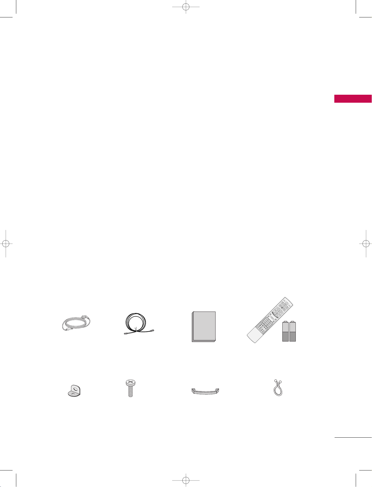
ACCESSORIES
ACCESSORIES
Ensure that the following accessories are included with your set. If any accessory is missing, please contact
the dealer from where you purchased the set.
Power Cord
2-TV brackets
2-Wall brackets
75 Ω RF Coaxial
2-bolts
Owner’s Manual
Cable
Management
(Refer to p.10)
Remote Control /
Batteries
Twister Holder
Arrange the wires
with the twister holder.
1

9U1004A_01 06/6/27 2:09 PM Page 2
CONTENTS
ACCESSORIES . . . . . . . . . . . . . . . . . . . . . . . . . . . . . . . . . . . . . . . . .
INTRODUCTION
CONTENTS
Controls . . . . . . . . . . . . . . . . . . . . . . . . . . . . . . . . . . . . . . . . . . . . . . . . . . . . . . 4
Connection Options
Remote Control Key Functions
INSTALLATION
Desktop Pedestal Installation . . . . . . . . . . . . . . . . . . . . . . . . . . . . . 9
Stand Swivel
Wire Arrangement
Attaching the TV to a Wall
CONNECTIONS & SETUP
Antenna Connection
Insertion of CI Module
VCR Setup
External AV Source Setup
Picture Out Setup
Digital Audio Output
External Stereo
DVD Setup
HDSTB Setup
PC Setup
BASIC OPERATION
Turning on the set . . . . . . . . . . . . . . . . . . . . . . . . . . . . . . 27
Programme Selection . . . . . . . . . . . . . . . . . . . . . . . . . . . 28
Volume Adjustment . . . . . . . . . . . . . . . . . . . . . . . . . . . . . 28
. . . . . . . . . . . . . . . . . . . . . . . . . . . . . . . . . . . . . . . . . . . . . .
. . . . . . . . . . . . . . . . . . . . . . . . 6-8
. . . . . . . . . . . . . . . . . . . . . . . . . . . . . . . . . . . . . . . . . . . . . . . . . 9
. . . . . . . . . . . . . . . . . . . . . . . . . . . . . . . . . . . . . . . . . 10
. . . . . . . . . . . . . . . . . . . . . . . . . . . . . . . 11
. . . . . . . . . . . . . . . . . . . . . . . . . . . . . . . . . . . . . . 12
. . . . . . . . . . . . . . . . . . . . . . . . . . . . . . . . . . . 12
. . . . . . . . . . . . . . . . . . . . . . . . . . . . . . . . . . . . . . . . . . . . . . 13-15
. . . . . . . . . . . . . . . . . . . . . . . . . . . . . . . . 16
. . . . . . . . . . . . . . . . . . . . . . . . . . . . . . . . . . . . . . . . . 16
. . . . . . . . . . . . . . . . . . . . . . . . . . . . . . . . . . . . . 17
. . . . . . . . . . . . . . . . . . . . . . . . . . . . . . . . . . . . . . . . . . . . . 17
. . . . . . . . . . . . . . . . . . . . . . . . . . . . . . . . . . . . . . . . . . . . . 18-20
. . . . . . . . . . . . . . . . . . . . . . . . . . . . . . . . . . . . . . . . . . 21-23
. . . . . . . . . . . . . . . . . . . . . . . . . . . . . . . . . . . . . . . . . . . . . . . 24-26
1
SPECIAL FUNCTIONS
PIP/POP/Double Window
Watching PIP/Double Window/POP
5
Programme Selection for Sub Picture
Input Source Selection for Sub Picture
Sub Picture Size Adjustment
Moving the Sub Picture (PIP mode only)
Adjusting PIP Transparency (PIP mode only)
Swapping between main and sub pictures
POP (Picture-out-of-Picture: Programme Scan) . . . 31
TELETEXT -In Digital mode
Teletext within Digital Service . . . . . . . . . . . . . . . . . . . . . . . . . . . 32
Teletext in Digital Service
. . . . . . . . . . . . . . . . . . . . . . . . . . . . . . . . 32
TELETEXT-In Analogue mode
Switch on/off
SIMPLE Text
TOP Text
FASTEXT
Special Teletext Functions
. . . . . . . . . . . . . . . . . . . . . . . . . . . . . . . . . . . . . . . . . . . . . . 33
. . . . . . . . . . . . . . . . . . . . . . . . . . . . . . . . . . . . . . . . . . . . . . . .
. . . . . . . . . . . . . . . . . . . . . . . . . . . . . . . . . . . . . . . . . . . . . . . . . . . . 34
. . . . . . . . . . . . . . . . . . . . . . . . . . . . . . . . . . . . . . . . . . . . . . . . . . . .
. . . . . . . . . . . . . . . . . . . . . . . . . . . . . . . 35
EPG (Electronic Programme Guide)
- In Digital mode only
Switch on/off EPG . . . . . . . . . . . . . . . . . . . . . . . . . . . . . 36
Select a programme . . . . . . . . . . . . . . . . . . . . . . . . . . . . 36
Button Function in NOW/NEXT Guide Mode . . . . . 37
Button Function in 8 Days Guide Mode . . . . . . . . . . 37
Button Function in Date Change Mode . . . . . . . . . . . 37
Button Function in Extended Description Box . . . . . 38
Button Function in Record/Remind Setting Mode . . . . . 38
Button Function in Timer List Mode . . . . . . . . . . . . . . 38
. . . . . . . . . . . . . . . . . . . 29
. . . . . . . . . . . . . . . . . 29
. . . . . . . . . . . . . . . 30
. . . . . . . . . . . . . . . . . . . . . . . . . . . . 30
. . . . . . . . . . . . . 30
. . . . . . . . 31
. . . . . . . . . . . . 31
33
34
2

9U1004A_01 06/6/27 2:09 PM Page 3
TV MENU
On Screen Menus Selection and Adjustment . . . . . . . . . 39
STATION MENU OPTIONS
Auto programme-In Digital Mode
Manual Programme Tuning -In Digital Mode
Programme Edit -In Digital Mode
CI [Common Interface] Information -In Digital Mode only
5V Antenna Power -In Digital Mode only
Booster -In Digital Mode only
Diagnostics -In Digital Mode only
Auto Programme Tuning -In Analogue Mode
Manual Programme Tuning -In Analogue Mode
Fine Tuning -In Analogue Mode
Assigning a Station Name -In Analogue Mode
Programme Edit -In Analogue Mode
Favourite Programme -In Analogue Mode
Calling the Programme Table
PICTURE MENU OPTIONS
Picture Status Memory (PSM) . . . . . . . . . . . . . . . . . . . . . . . . . . . 56
Picture Adjustment (PSM-User option)
Colour Status Memory (CSM)
Manual Colour Temperature Control (CSM - User option)
XD Function
XD - User Option
NR (Noise Reduction)
Advanced
Advanced-Cinema
Advanced-Black Level
Reset
. . . . . . . . . . . . . . . . . . . . . . . . . . . . . . . . . . . . . . . . . . . . . . . . . 60
. . . . . . . . . . . . . . . . . . . . . . . . . . . . . . . . . . . . . . . . . . 60
. . . . . . . . . . . . . . . . . . . . . . . . . . . . . . . . . . . . . 61
. . . . . . . . . . . . . . . . . . . . . . . . . . . . . . . . . . . . . . . . . . . . . . . . 62-63
. . . . . . . . . . . . . . . . . . . . . . . . . . . . . . . . . . . . . . . . 62
. . . . . . . . . . . . . . . . . . . . . . . . . . . . . . . . . . . . . . . . . . . . . . . . . . . . . . . . . . 64
. . . . . . . . . . . . . . . . . . . . . . . . . . . 46
. . . . . . . . . . . . . . . . . . . . . . . . . . . . 50
. . . . . . . . . . . . . . . . . . . . . . . . . . . . . 55
. . . . . . . . . . . . . . . . . . . . . . . . . . . 58
. . . . . . . . . . . . . . . . . . . . . . . . . . . . . . . . . . . . 63
. . . . . . . . . . . . . . . . . . . . . . . 40
. . . . . . . . . . . 41
. . . . . . . . . . . . . . . . . . . 42-43
. . . . . . . . 44
. . . . . . . . . . . . . . 45
. . . . . . . . . . . . . . . . . . . . . . . 47
. . . . . . . . . . . . . . 48
. . . . . . . . . . . 49
. . . . . . . . . . . . 51
. . . . . . . . . . . . . . . . 52-53
. . . . . . . . . . . . . . 54
. . . . . . . . . . . . . . . . 57
. . . . . . . . 59
TIME MENU OPTIONS
Clock Setup . . . . . . . . . . . . . . . . . . . . . . . . . . . . . . . . . . . . . . . . . . . . . . . . 72
On/Off Time
Auto Sleep
Sleep Timer
. . . . . . . . . . . . . . . . . . . . . . . . . . . . . . . . . . . . . . . . . . . . . . . 73
. . . . . . . . . . . . . . . . . . . . . . . . . . . . . . . . . . . . . . . . . . . . . . . . . . 74
. . . . . . . . . . . . . . . . . . . . . . . . . . . . . . . . . . . . . . . . . . . . . . . . 75
SPECIAL MENU OPTIONS
System Lock Setting . . . . . . . . . . . . . . . . . . . . . . . . . . . . . . . . . . . . . . 76
Child Lock
Factory Reset
Software Update -In Digital mode only
Subtitle Language -In Digital mode only
Index
. . . . . . . . . . . . . . . . . . . . . . . . . . . . . . . . . . . . . . . . . . . . . . . . . . 77
. . . . . . . . . . . . . . . . . . . . . . . . . . . . . . . . . . . . . . . . . . . . . . . 78
. . . . . . . . . . . . . . . 79
. . . . . . . . . . . . . 80
. . . . . . . . . . . . . . . . . . . . . . . . . . . . . . . . . . . . . . . . . . . . . . . . . . . . . . . . . 81
SCREEN MENU OPTIONS
Auto Configure- RGB [PC] mode only . . . . . . . . . . . . . . . . 82
Manual Configure
Setting the Picture Format
Selecting Wide XGA mode
XD demo
. . . . . . . . . . . . . . . . . . . . . . . . . . . . . . . . . . . . . . . . . . . . . . . . . . . 86
Initializing (Reset to original factory settings)
. . . . . . . . . . . . . . . . . . . . . . . . . . . . . . . . . . . . . . . . .
. . . . . . . . . . . . . . . . . . . . . . . . . . . . . . 84
. . . . . . . . . . . . . . . . . . . . . . . . . . . . . . . . . .
. . . . . . . 87
APPENDIX
External Control Device Setup . . . . . . . . . . . . . . .88-95
IR Codes . . . . . . . . . . . . . . . . . . . . . . . . . . . . . . . . .96-97
Programming the Remote Control . . . . . . . . . . . . . . . 98
Programming Codes . . . . . . . . . . . . . . . . . . . . . . 99-100
Troubleshooting Checklist . . . . . . . . . . . . . . . . . 101-102
Maintenance . . . . . . . . . . . . . . . . . . . . . . . . . . . . . . . 103
Product Specifications . . . . . . . . . . . . . . . . . . . . . . . 104
CONTENTS
83
85
SOUND MENU OPTIONS
Sound Status Memory (SSM) . . . . . . . . . . . . . . . . . . . . . . . . . . . . . . 65
Sound Frequency Adjustment (SSM - User option)
Auto Volume Leveler (AVL)
Balance Adjustment
TV Speaker
. . . . . . . . . . . . . . . . . . . . . . . . . . . . . . . . . . . . . . . . . . . . . . . . . . . 69
. . . . . . . . . . . . . . . . . . . . . . . . . . . . . . . . 67
. . . . . . . . . . . . . . . . . . . . . . . . . . . . . . . . . . . . . . . . 68
Audio Language -In Digital mode only
Stereo/Dual Reception -In Analogue mode only
NICAM Reception -In Analogue mode only
Speaker Sound Output Selection
. . . . . . . . . . . . . . . . . . . . . . . . 71
. . . . . . . . . 66
. . . . . . . . . . . . . . . . . . 70
. . . . . . . . . 71
. . . . . . . . . . . 71
3
PR
VOL
MENU
OK
INPUT
9U1004A_01 06/6/27 2:09 PM Page 4
INTRODUCTION
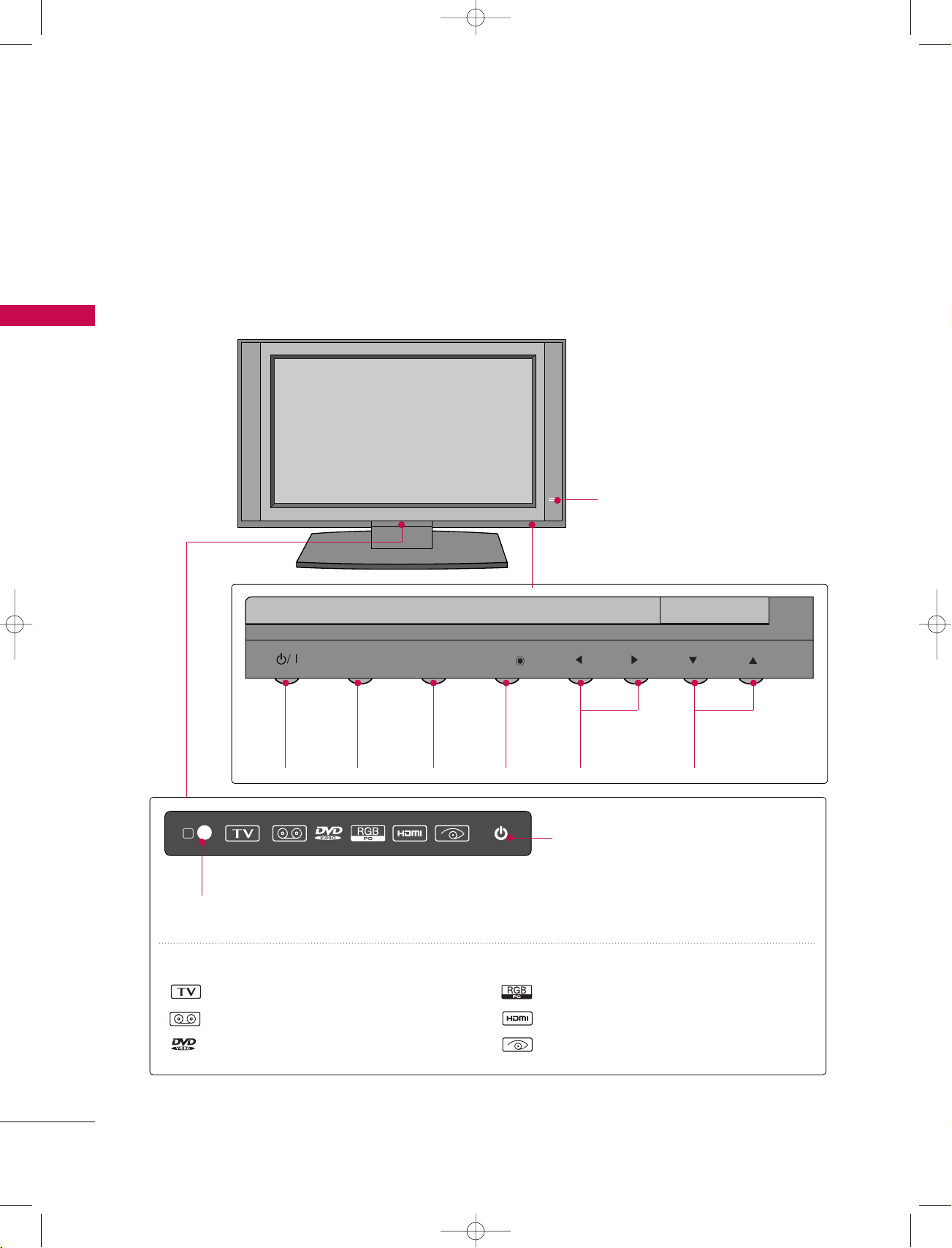
CONTROLS
■
Here shown may be somewhat different from your TV.
Front Panel Controls
INTRODUCTION
POWER
Button
R
Remote Control Sensor
INPUT
INPUT
Button
MENU
MENU
Button
OK
OK
Button
Intelligent Eye
Adjusts picture according to the
surrounding conditions.
VOL
VOLUME
FF,GG
)Buttons
(
PR
PROGRAMME
EE,DD
)Buttons
(
Power Standby Indicator
• illuminates red in standby mode.
• illuminates white when the set is
switched on.
INDEX
TV mode
AV mode
Component mode
RGB-PC mode
HDMI1/DVI or HDMI2 mode
Intelligent Eye
4
PCMCIA
CARD SLOT
S-VIDEOVIDEO AUDIO
AV IN 4
L/MONO R
S-VIDEOVIDEO AUDIO
AV IN 4
L/MONO R
PCMCIA
CARD SLOT
HDMI INHDMI IN
2
1(D1(DVI)VI)
DIGITAL AUDIO
OUT
OPTICAL
RS-232C IN
(CONTR(CONTROLOL & SERSERVICE)VICE)
VIDEO
AUDIO
MONO
( )
COMPONENT IN
S-VIDEO
VARIABLE
AUDIO OUT
AV IN 3
AV 1 AV 2 DTV OUT
VIDEO
AUDIO
RGB (PCRGB (PC/DTV)DTV)
OUT
RGB INRGB IN
AUDIO (RGB/DVI)AUDIO (RGB/DVI)
IN
ANTENNAANTENNA
OUTOUT
ANTENNAANTENNA
IN
REMOTE
CONTROL
9U1004A_01 06/8/24 5:34 PM Page 5
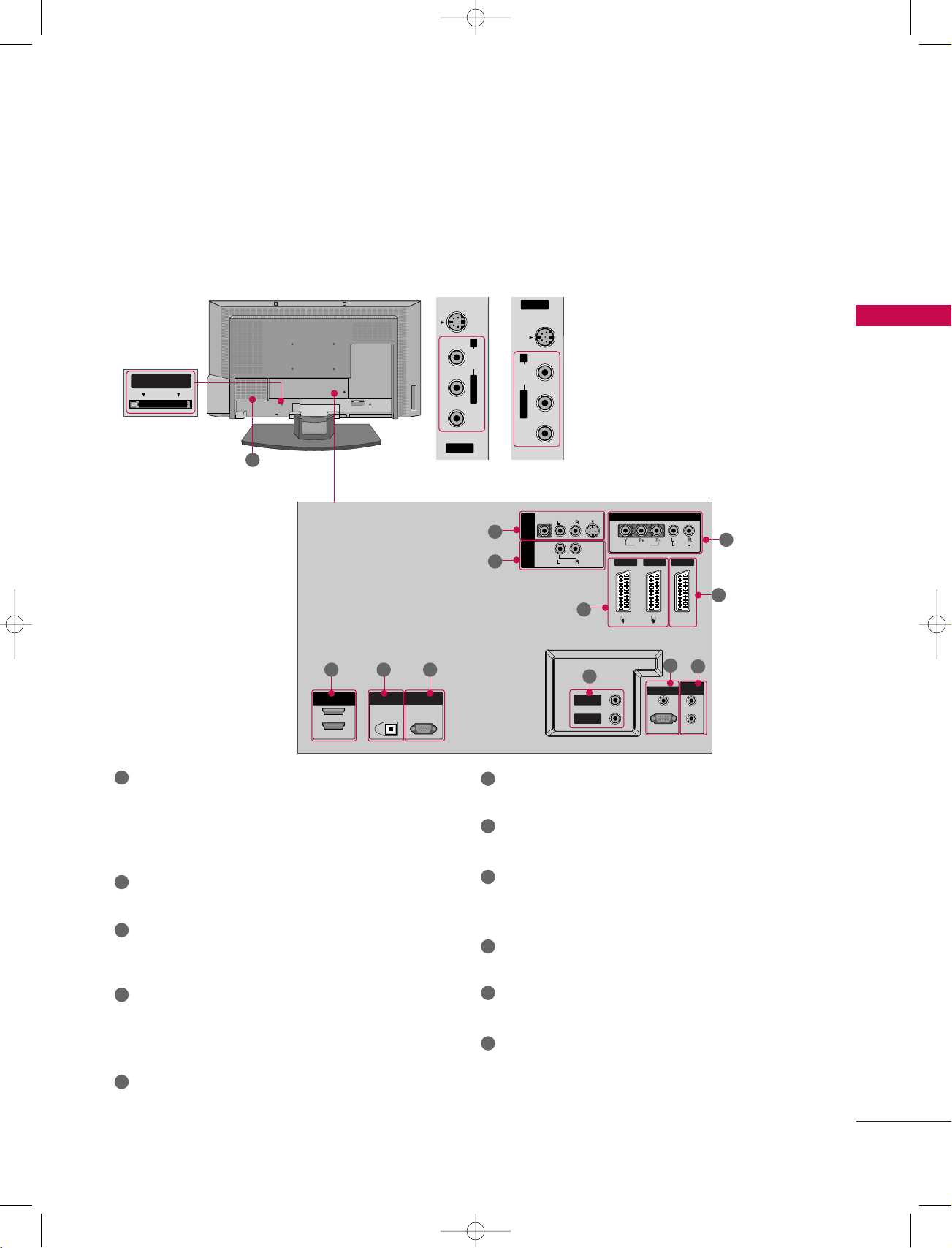
CONNECTION OPTIONS
■
Here shown may be somewhat different from your set.
Back Connection Panel
PCMCIA CARD
SLOT
(Personal Computer
Memory Card
International
Association)
Card Slot
11
37LB1D/1DB
32LB1D/1DB
42LB1D/1DB
S-VIDEO Input
Provides better picture quality than
the video input.
INTRODUCTION
AUDIO Input
Connections are available for listening to stereo sound from an external
device.
VIDEO Input
Connects the video signal from a
video device.
1
2
1
4
5 6
7
8
3
10
9
1
AV (Audio/Video) IN 1-3
Connect audio/video output from an external
6
RS-232C IN (CONTROL & SERVICE) PORT
Connect to the RS-232C port on a PC.
device to these jacks.
7
S-VIDEO
Connect S-Video out from an S-VIDEO device.
2
VARIABLE AUDIO
Connect a external stereo amplifier.
3
COMPONENT IN
Connect a component video/audio device to these
jacks.
4
HDMI IN
Connect a HDMI signal to 1(DVI) or 2.
Or DVI(VIDEO)signal to the 1(DVI) port with a
HDMI to DVI cable.
5
DIGITAL AUDIO OUT
Connect digital audio from various types of equipment.
Note: In standby mode, these ports do not work.
ANTENNA IN / ANTENNA OUT
Connect cable signals to this jack.
8
RGB/AUDIO IN
Connect the monitor output from a PC to the
appropriate input port.
Remote Control Port
9
Connect your wired remote control.
10
DTV OUT
Connect a second TV or monitor.
11
Power Cord Socket
For operation with AC power.
Caution:
Never attempt to operate the TV on DC power.
5

l/ll
TIME
INDEX
REVEAL
1 2 3
4 5 6
7809
Q.VIEWLIST
VOL PR
MUTE
FAV
MENU
TEXT
SWAP
PIP PR+
BACK
INFO i
EXIT
OK
POWER
PIP PR-
PIP
SLEEP
PIP INPUT
VCR
TV
DVD
GUIDE
ARC
D/A TV
INPUT
SUBTITLE/
?
i
SIZE
POSITION
9U1004A_01 06/6/27 2:34 PM Page 6
INTRODUCTION
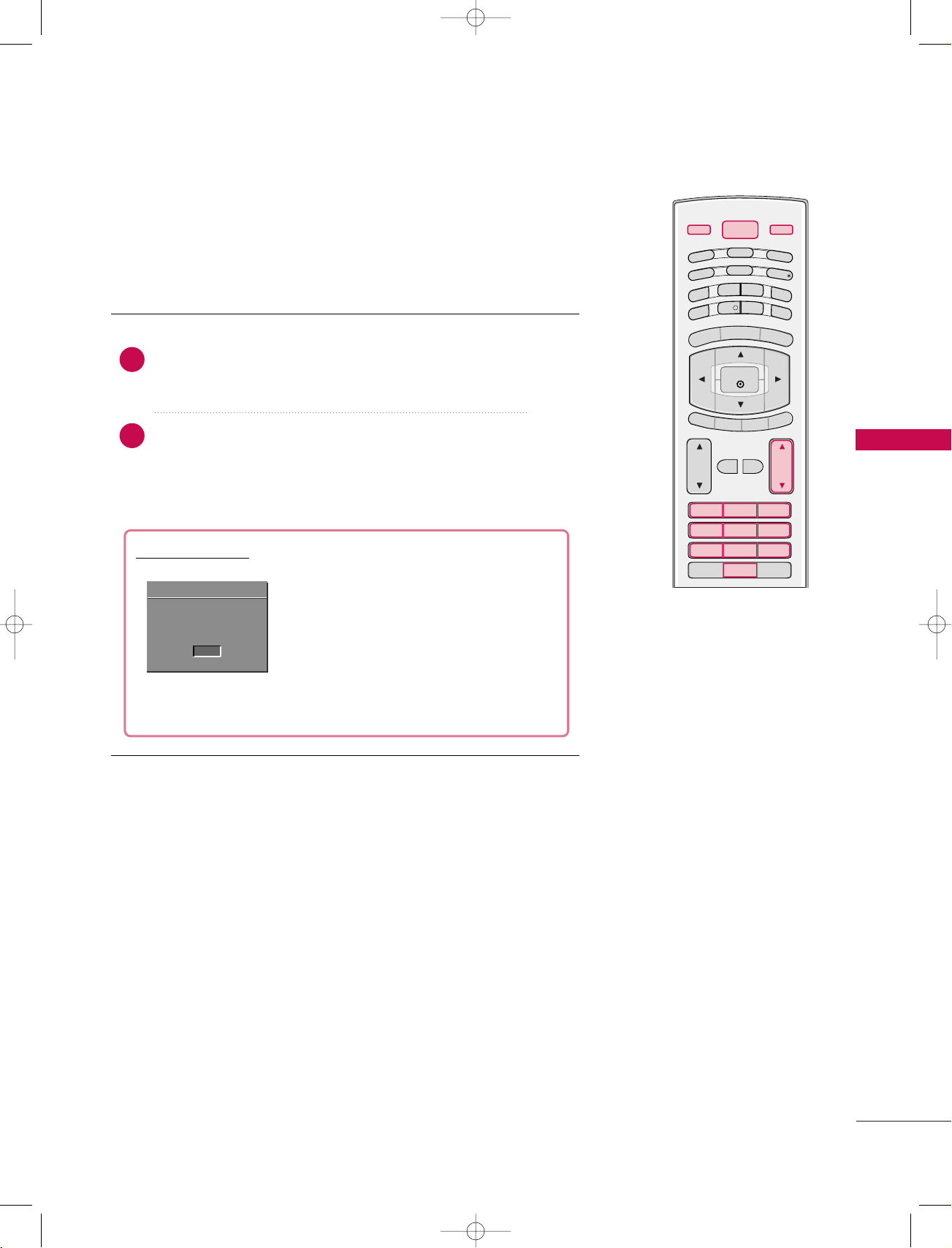
REMOTE CONTROL KEY FUNCTIONS
When using the remote control, aim it at the remote control sensor on the TV.
INTRODUCTION
THUMBSTICK
D/A TV
(Digital TV
/Analogue TV)
POWER
INPUT
MENU
EXIT
(Up/Down
/Left/Right)
COLOURED
BUTTONS
OK
VOLUME UP
/DOWN
Selects digital or analogue mode.
Switches the set between ON and STANDBY.
Selects the DTV, TV, AV, Component, RGB or
HDMI/DVI modes.
Switches the set on from standby.
Displays on screen menus one by one.
Exits the current menu.
Memorizes menu changes.
Clears all on-screen displays and returns to TV viewing
from any menu.
Adjusts menu settings.
Selects menu item.
Accepts your selection or displays the current mode.
They are used as per the indications or functions displayed on TV screen in case of Text displays (Teletext,
EPG) and programme edit.
Increases/decreases sound level.
2
FAV
PROGRAMME
NUMBER button
control buttons
6
MUTE
(FAVOURITE)
UP/DOWN
LIST
Q.VIEW
I/II
VCR/DVD
Switches the sound on or off.
Displays the selected favourite programmes.
Selects a programme.
Displays the programme table.
GG
pp..5555
Returns to the previously viewed programme.
Selects the language during dual language broadcast.
pp..7711
GG
Selects the sound output.
GG
pp..7711
Control video cassette recorders or DVD players.
1
M
E
N
U
TEXT
SWAP
PIP PR+
BACK
INFO i
E
X
I
T
POWER
P
IP
P
R
-
P
I
P
SLEEP
PIP INPUT
V
C
R
T
V
DVD
G
U
ID
E
ARC
D/A TV
INPUT
S
U
B
T
IT
L
E
/
9U1004A_01 06/6/27 2:34 PM Page 7
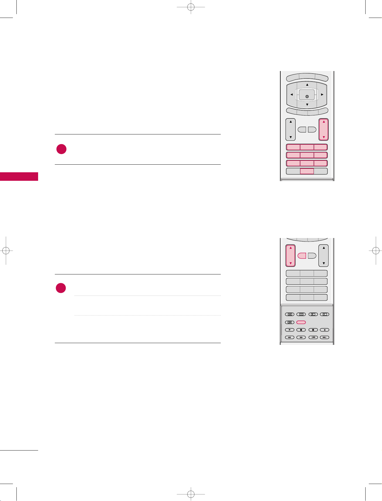
TV, DVD, VCR
GUIDE
ARC
(Aspect Ratio Control)
SUBTITLE/
*
PIP
PIP PR +/-
SWAP
PIP INPUT
1
SIZE
1
POSITION
BACK
SLEEP
2
TELETEXT
BUTTONS
Select the remote operating mode: TV, DVD, or VCR.
GG
GG
GG
pp..3366
pp..2299
pp..3300
GG
GG
pp..3300
pp..8844
GG
GG
pp..3311
pp..8800
GG
pp..3300
pp..2299--3311
GG
Shows programme schedule.
Selects your desired picture format.
Recalls your preferred subtitle in digital mode.
Switches the sub picture PIP, POP, Double Window or off mode.
Selects the PIP programme.
Alternates between main and sub picture.
Select the connected input source for the sub-picture.
Adjusts the sub picture size.
Moves the sub picture position.
Allow the user to move back one step in an interactive application, EPG or other user interaction function.
Sets the sleep timer.
GG
pp..7755
These buttons are used for teletext.
Text button is used to enable teletext services while other buttons are for teletext functions.
* For further details, see the ‘Teletext’ section.
pp..3322--3355
GG
INTRODUCTION
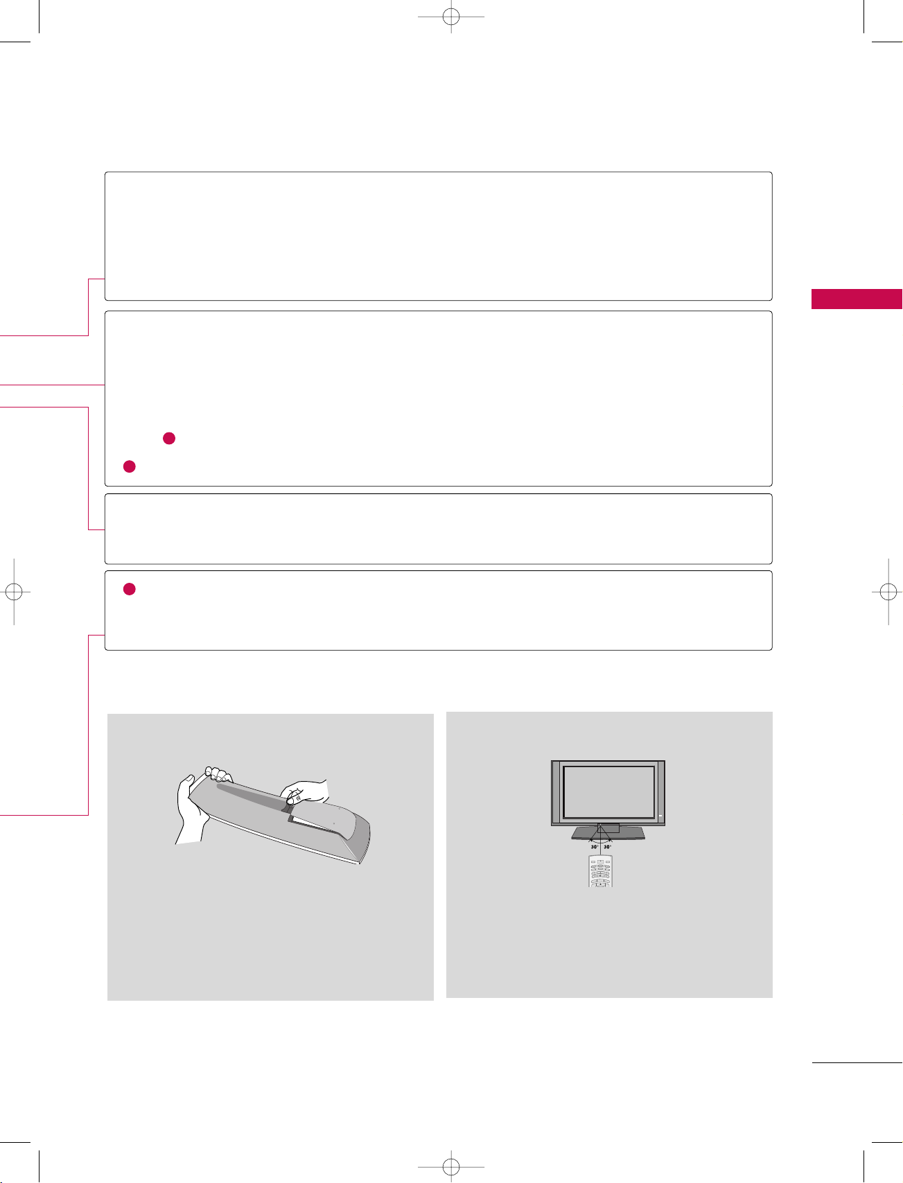
Installing Batteries Remote control effective range
■
Open the battery compartment cover on the back
side and install the batteries matching correct
polarity (+with +,-with -).
■
Install two 1.5V AA batteries. Don’t mix old or
used batteries with new ones.
■
Close cover.
■
Use a remote control up to 7 meters distance and
30 degree (left/right) within the receiving unit
scope.
■
Dispose of used batteries in a recycle bin to
preserve environment.
7
l/ll
TIME
INDEX
REVEAL
1 2 3
4 5 6
7809
Q.VIEWLIST
VOL PR
MUTE
FAV
MENU
TEXT
SWAP
PIP PR+
BACK
INFO i
EXIT
OK
POWER
PIP PR-
PIP
SLEEP
PIP INPUT
VCR
TV
DVD
GUIDE
ARC
D/A TV
INPUT
SUBTITLE/
?
i
SIZE
POSITION
9U1004A_01 06/6/27 2:09 PM Page 8
INTRODUCTION
INTRODUCTION
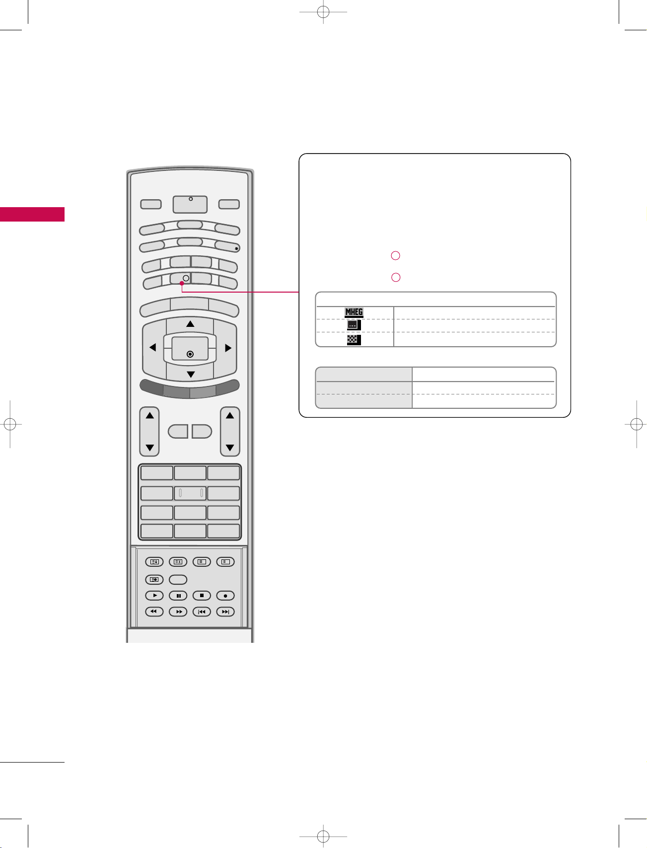
Brief Info.
What is Brief Info?
: Brief Info shows the present screen information.
: On Watching with the upper Input signal, press the INFO
button.
How to use?
1. Press the INFO i button to show the Brief Info on the
screen.
2. Press the INFO i button or EXIT button to exit.
Icon Function in Info. description Box
MHEG Programme
Subtitle Programme
Scramble Programme
Remote Control Buttons
F / G Change to Now/Next
D / E
Function
The detail information on or off
8
9U1004A_01 06/6/27 2:09 PM Page 9
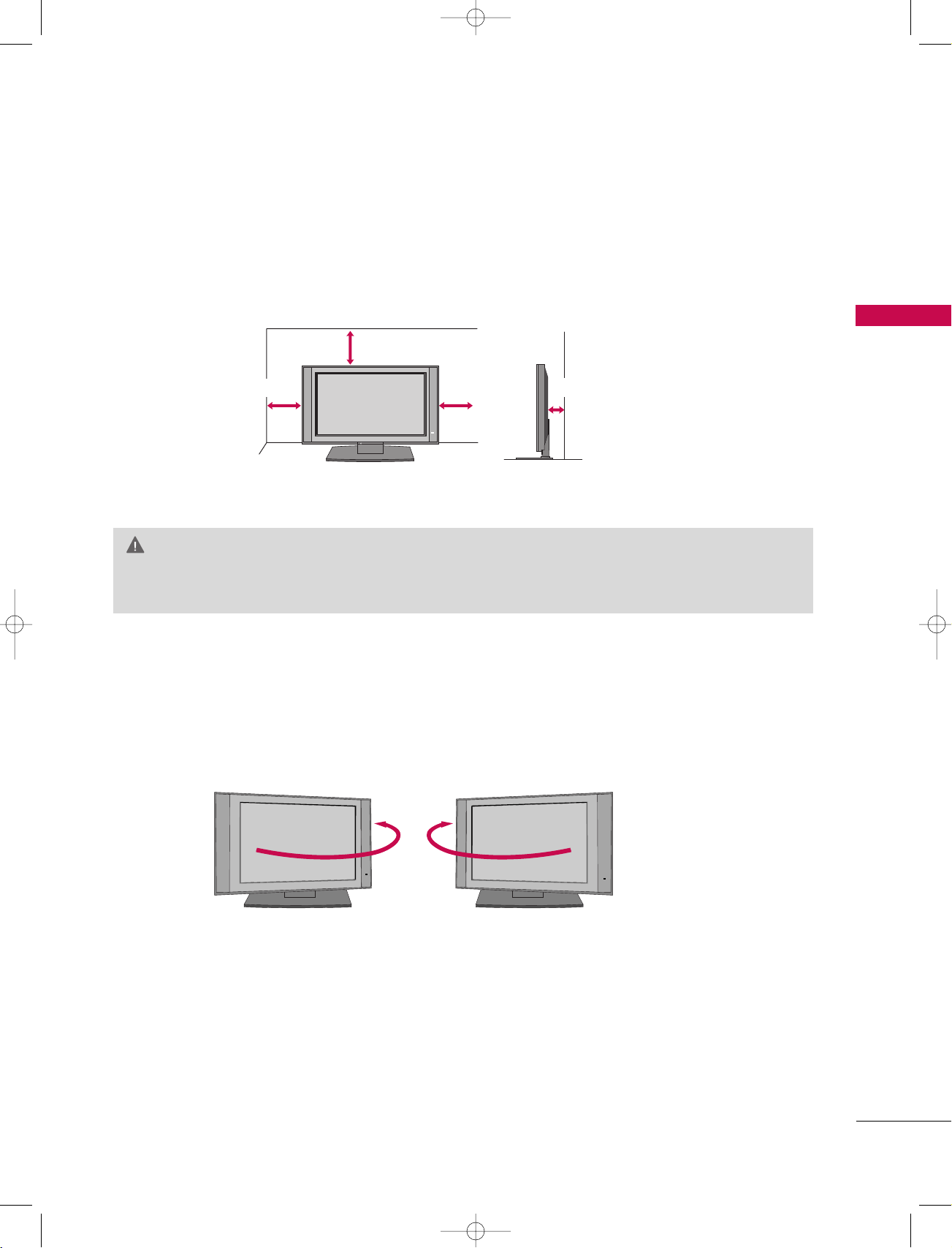
DESKTOP PEDESTAL INSTALLATION
For proper ventilation, allow a clearance of 4inches on each side from the wall.
4 inches
4 inches
4 inches
CAUTION
Ensure adequate ventilation by following the clearance recommendations.
GG
SWIVEL STAND
INTRODUCTION
4 inches
The TV can be conveniently swivelled on its stand 30° to the left or right to provide the optimum
viewing angle.
9
!
9U1004A_01 06/6/27 2:10 PM Page 10
INSTALLATION
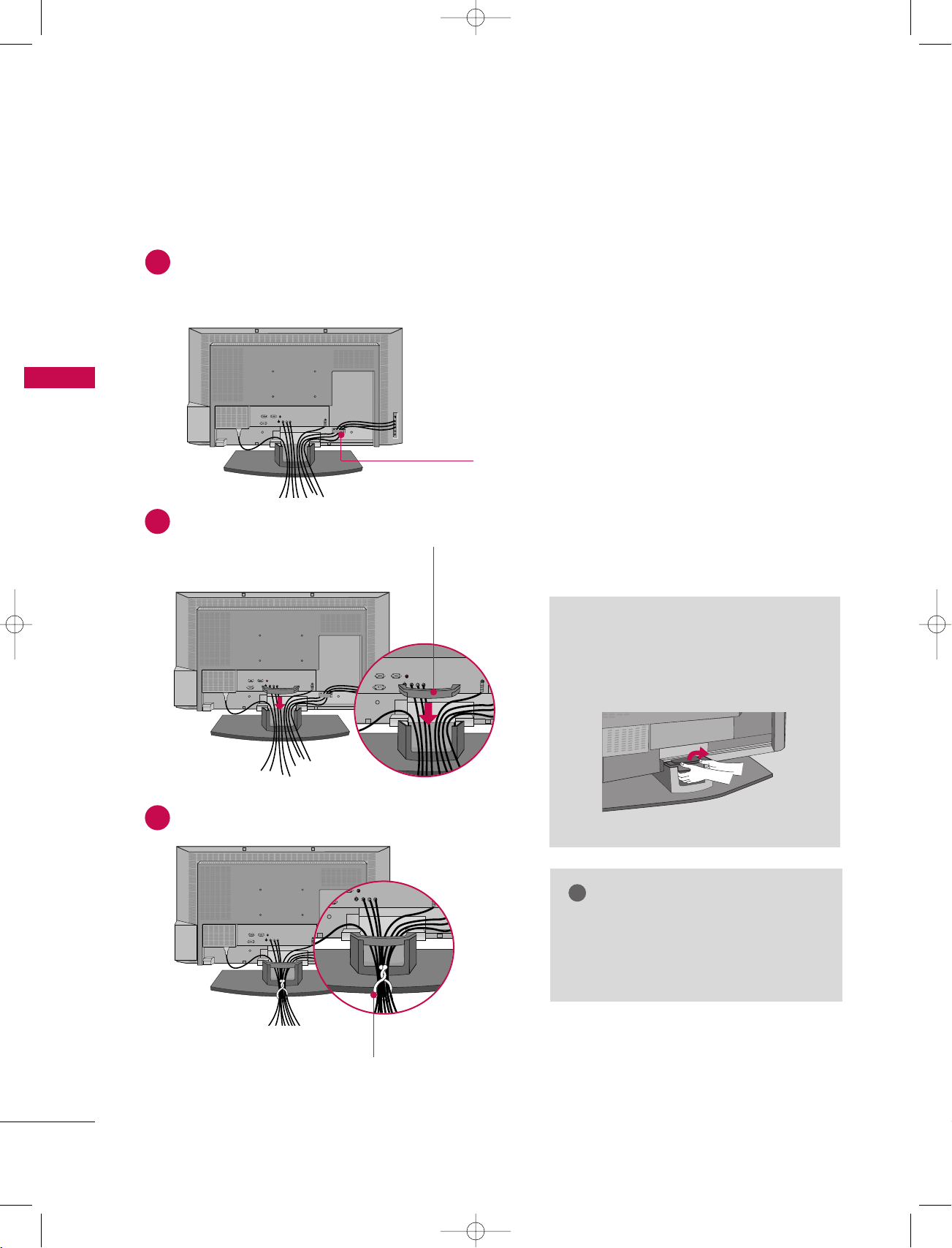
WIRE ARRANGEMENT
Connect the cables as necessary.
1
After connecting the cables neatly, arrange the cables to the Cable Holder.
To connect an additional equipment, see the CONNECTIONS & SETUP section.
INSTALLATION
CABLE HOLDER
Install the CABLE MANAGEMENT as shown.
2
CABLE MANAGEMENT
Bundle the cables using the supplied twister holder.
3
How to remove the CABLE
MANAGEMENT
Hold the CABLE MANAGEMENT
GG
with both hands and pull it upward.
NOTE
Do not hold the CABLE MANAGEMENT
GG
when moving the product.
- If the product is dropped, you may be
injured or the product may be broken.
TWISTER HOLDER
10
9U1004A_01 06/6/27 2:10 PM Page 11
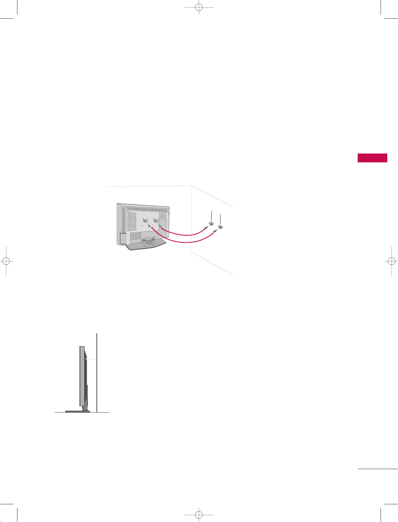
ATTACHING THE TV TO A WALL
We recommend that you set up the TV close to a wall so it cannot fall over if pushed backwards.
Additionally, we recommend that the TV be attached to a wall so it cannot be pulled in a forward direction,
potentially causing injury or damaging the product.
Caution: Please make sure that children don’t climb on or hang from the TV.
INSTALLATION
■
Insert the TV brackets and bolts to tighten the product to the wall as shown in the picture.
Secure the wall brackets with the bolts (not provided as parts of the product, must purchase separately) on
the wall. Match the height of the bracket that is mounted on the wall to the holes in the product.
Ensure the brackets are tightened securely.
■
Use a sturdy rope (not provided as parts of the product, must purchase separately) to tie the product. It is safer to tie the rope so it becomes horizontal between the wall and the product.
11
AV 1 AV 2 DTV OUT
ANTENNA
OUT
ANTENNA
IN
PCMCIAPCMCIA
CARD SLOT
TVTV
ANTENNA
IN
!
ANTENNA
IN
9U1004A_01 06/6/27 2:10 PM Page 12
CONNECTIONS & SETUP
- All cables shown are not included with the TV.
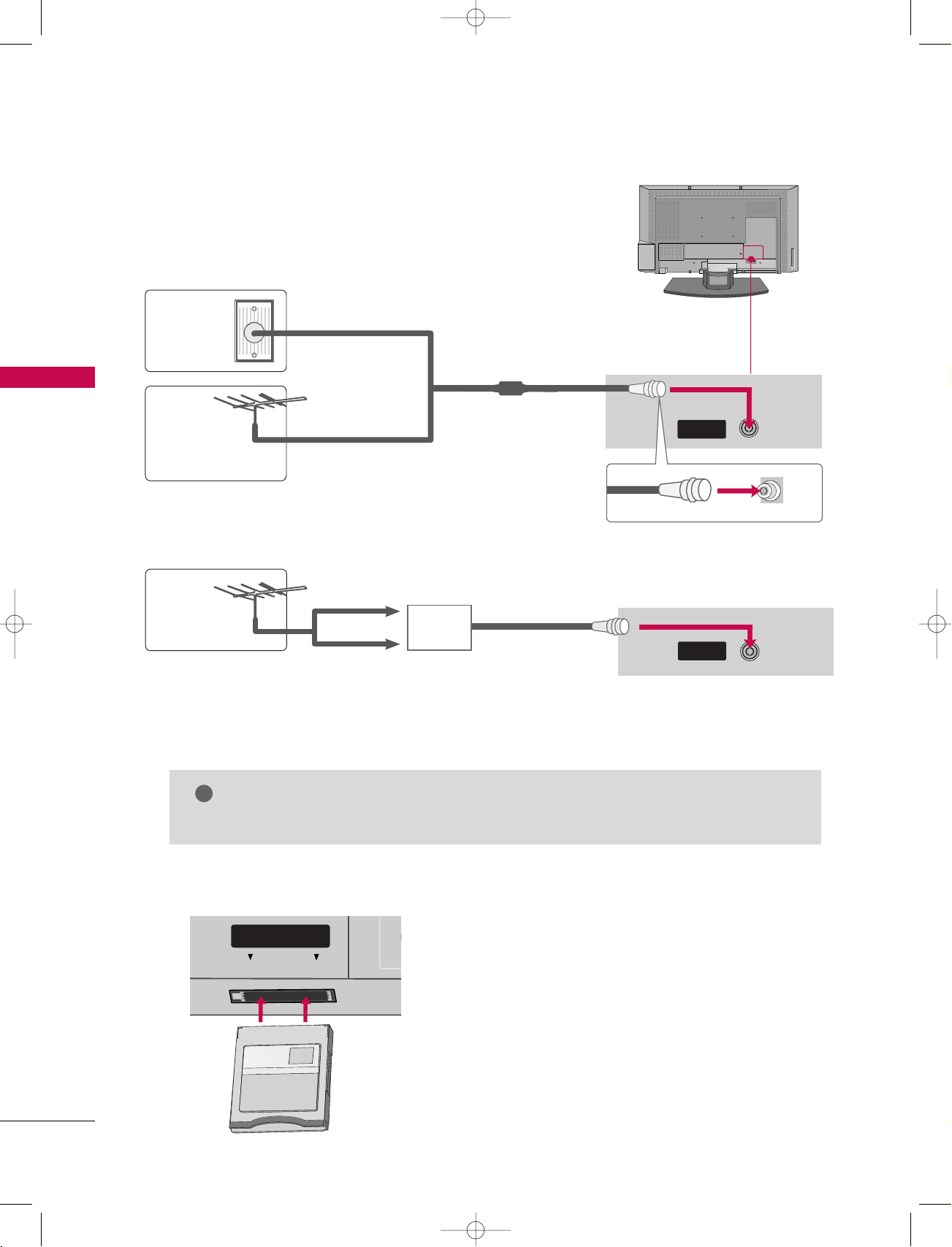
ANTENNA CONNECTION
- For optimum picture quality, adjust antenna direction if needed.
CONNECTIONS & SETUP
Wall
Multi-family Dwellings/Apartments
(Connect to wall antenna socket)
Antenna
Socket
Outdoor
RF Coaxial Wire (75 ohm)
Antenna
(VHF, UHF)
Single-family Dwellings /Houses
(Connect to wall jack for outdoor antenna)
- 5V antenna power works In Digital mode
only. (Refer to p. 45)
Antenna
■
To improve the picture quality in a poor signal area, please purchase a signal amplifier and install properly.
■
If the antenna needs to be split for two TV’s, install a 2-Way Signal Splitter.
■
If the antenna is not installed properly, contact your dealer for assistance.
UHF
VHF
Signal
Amplifier
NOTE
The TV will let you know when the analogue, cable, and digital programme scans are complete.
GG
INSERTION OF CI MODULE
-- TT oo vv ii eeww tthh ee ss cc rraammbblleedd ((ppaayy )) sseerrvviicc eess
iinn ddiigg iitt aall TTVV mmooddee
Insert the CI Module to PCMCIA (Personal
Computer Memory Card International
12
Association) CARD SLOT of TV as shown.
For further information, see p.44.
AV 1 AV 2 DTV OUT
RGB (PC/DTV)
AUDIO (RGB/DVI)
OUT
IN
REMOTE
CONTROL
RGB IN
REMOTE
CONTROL
ANTENNAANTENNA
ININ
L R
S-VIDEO VIDEO
ANT IN
ANT OUT
ANTENNAANTENNA
OUTOUT
9U1004A_01 06/6/27 2:10 PM Page 13
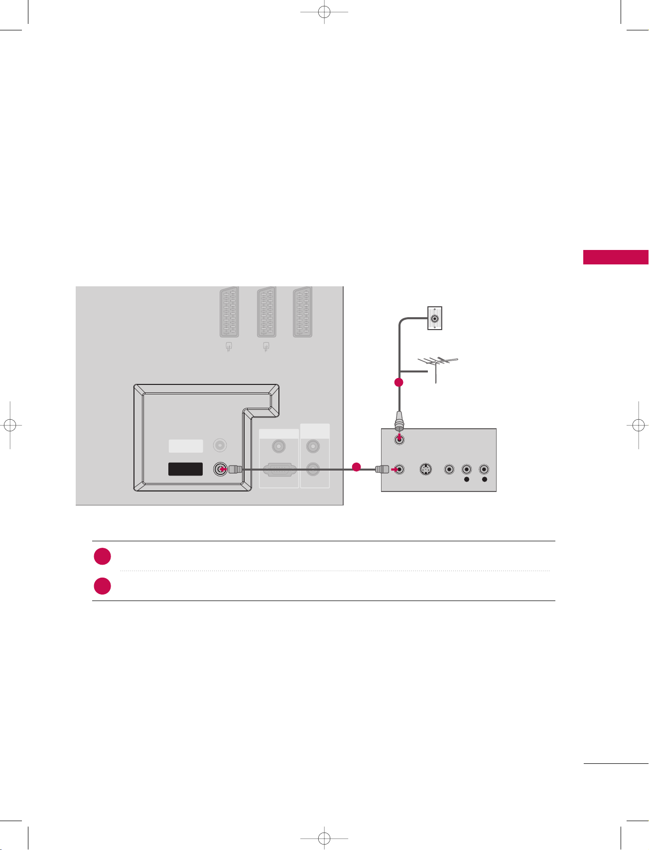
VCR SETUP
■
To avoid picture noise (interference), leave an adequate distance between the VCR and TV
■
If the 4:3 picture format is used; the fixed images on the sides of the screen may remain visible on the
screen. This phenomenon is common to all manufactures and in consequence the manufactures warranty
does not cover the product bearing this phenomenon.
When connecting with an antenna
CONNECTIONS & SETUP
1. How to connect
Connect the RF antenna out socket of the VCR to the
1
Connect the antenna cable to the RF antenna in socket of the VCR.
2
2. How to use
1
AA nntteennnnaa
Wall Jack
2
Antenna
socket on the set.
■
Press the PLAY button on the VCR and match the appropriate programme between the TV and VCR
for viewing.
13
!
AV 1 AV 2 DTV OUT
ANTENNA
IN
VIDEO
COM
AV IN 3
VIDEO
AUDI O
MONO
( )
S-VIDEO
L R
S-VIDEOVIDEO ANT IN
ANT OUT
ANTENNA
OUT
V
C
VARIABLE
AV 1AV 1 AV 2 DTV OUT
AV IN 3
VIDEO
AUDI O
MONO
( )
S-VIDEO
L R
S-VIDEOVIDEO ANT IN
ANT OUT
AV 2 DTV OUT
ANTENNA
OUT
ANTENNA
IN
AV 1
!
9U1004A_01 06/6/27 2:10 PM Page 14
CONNECTIONS & SETUP
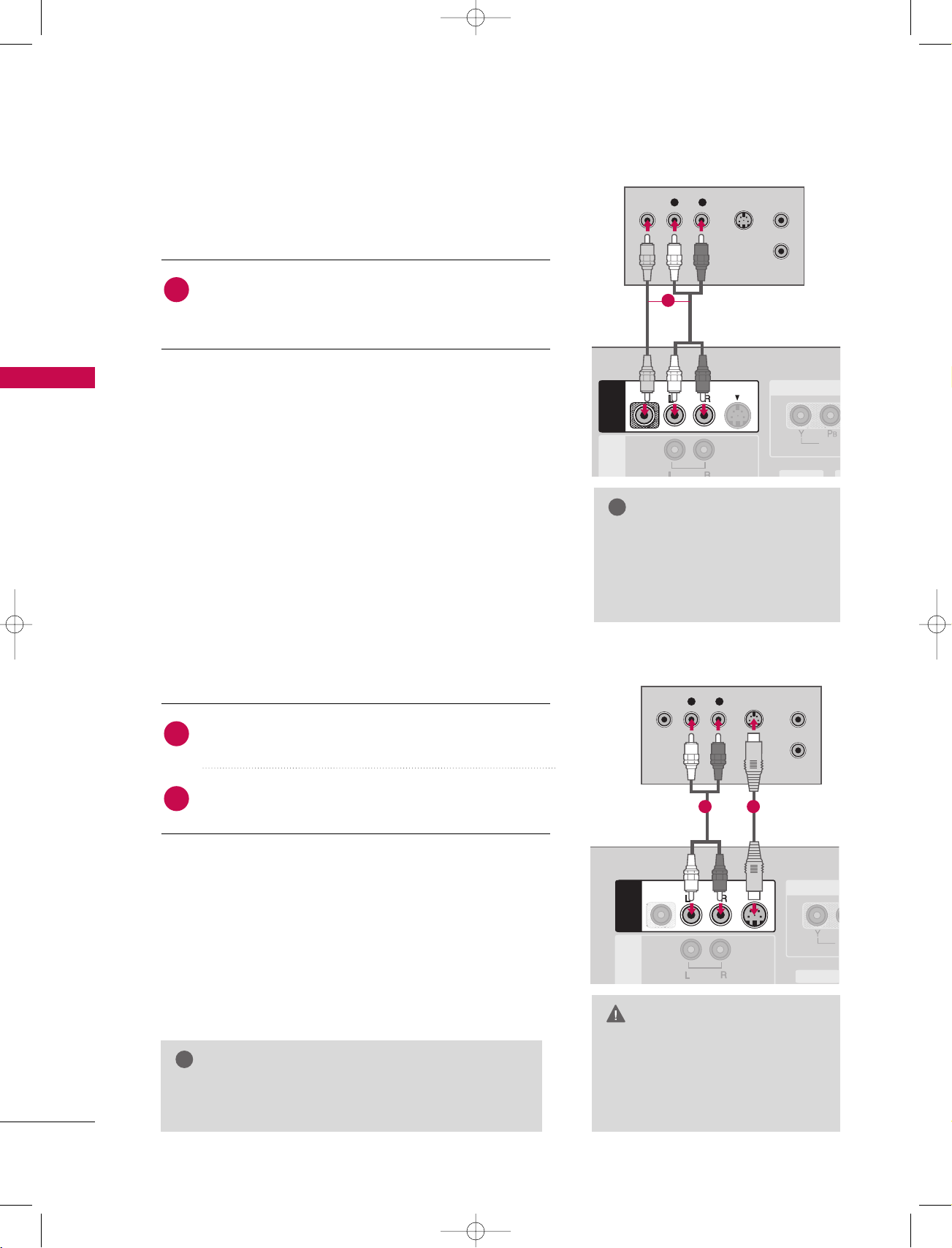
When connecting with a RCA cable
CONNECTIONS & SETUP
1. How to connect
Connect the
1
VCR. Match the jack colors (Video = yellow, Audio Left
AA UUDD IIOO/VV IIDD EEOO
jacks between TV and
= white, and Audio Right = red)
2. How to use
■
Insert a video tape into the VCR and press PLAY on the
AA VV 44
)
II NN PPUUTT
button on
input source.
VCR. (Refer to the VCR owner’s manual.
■
■
AA VV 33
Select
input source with using the
the remote control.
If connected to
AA VV IINN 44
, select
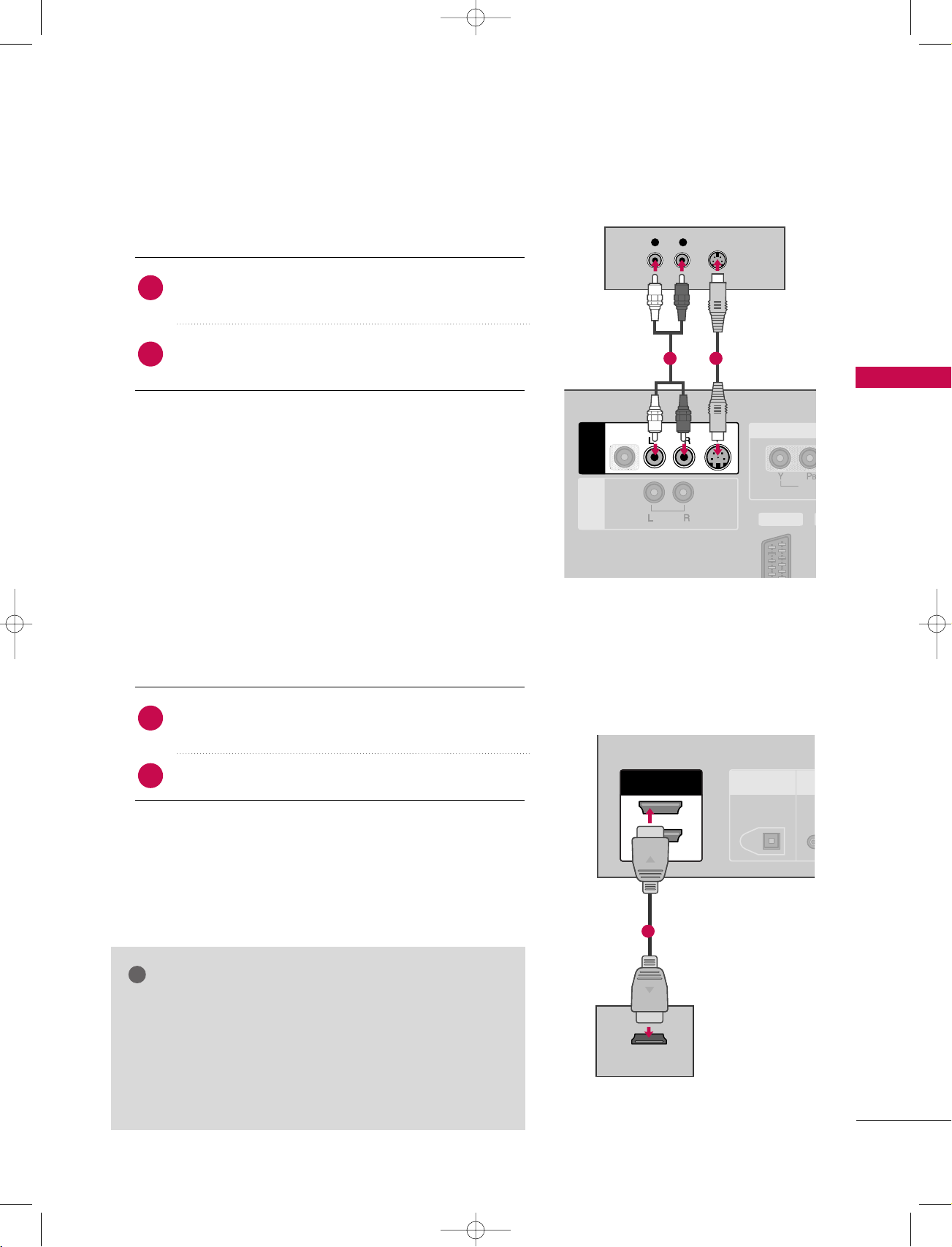
When connecting with an S-Video cable
1
NOTE
If you have a mono VCR, con-
GG
nect the audio cable from the
VCR to the
LL//MMOONNOO
AA UUDD IIOO
jack of the set.
1. How to connect
Connect the S-VIDEO output of the VCR to the
1
SS --VVII DDEE OO
input on the set.
Connect the audio outputs of the VCR to the
2
input jacks on the set.
2. How to use
■
Insert a video tape into the VCR and press PLAY on the VCR.
(
Refer to the VCR owner’s manual.
■
Select
the remote control.
■
If connected to
NOTE
The picture quality is improved: compared to normal
GG
composite (RCA cable) input.
AA VV 33
input source with using the
AA VV IINN 44
, select
)
AA VV 44
II NN PPUUTT
input source.
AA UUDD IIOO
button on
12
CAUTION
Do not connect to both Video
GG
and S-Video at the same time. In
the event that you connect both
Video and the S-Video cables,
only the S-Video will work.
14
VIDEO
AUDIO
COMPONENT IN
AV 2AV 2 DTV OUTDTV OUT
AV 1AV 1
L R
VIDEO
/AUDIO
AUDI O
!
9U1004A_01 06/6/27 2:10 PM Page 15
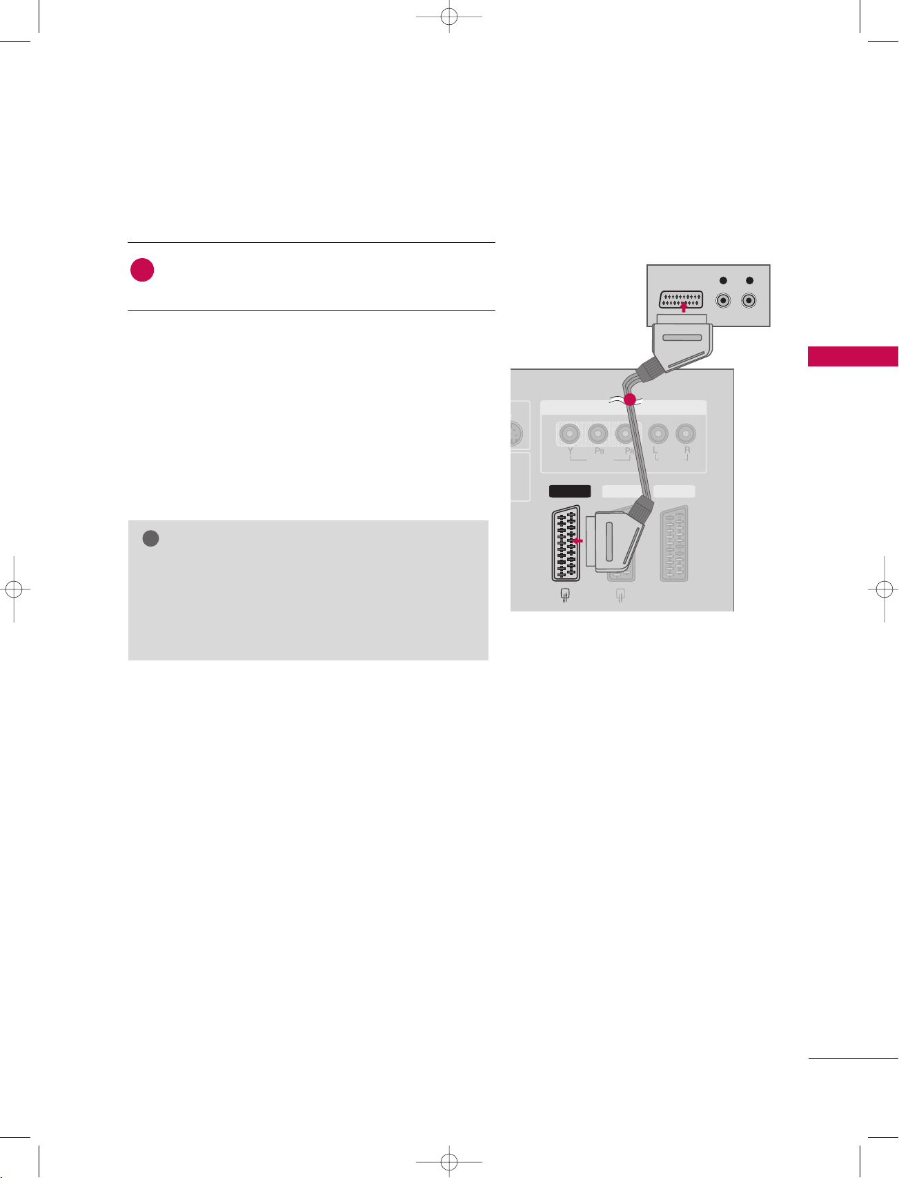
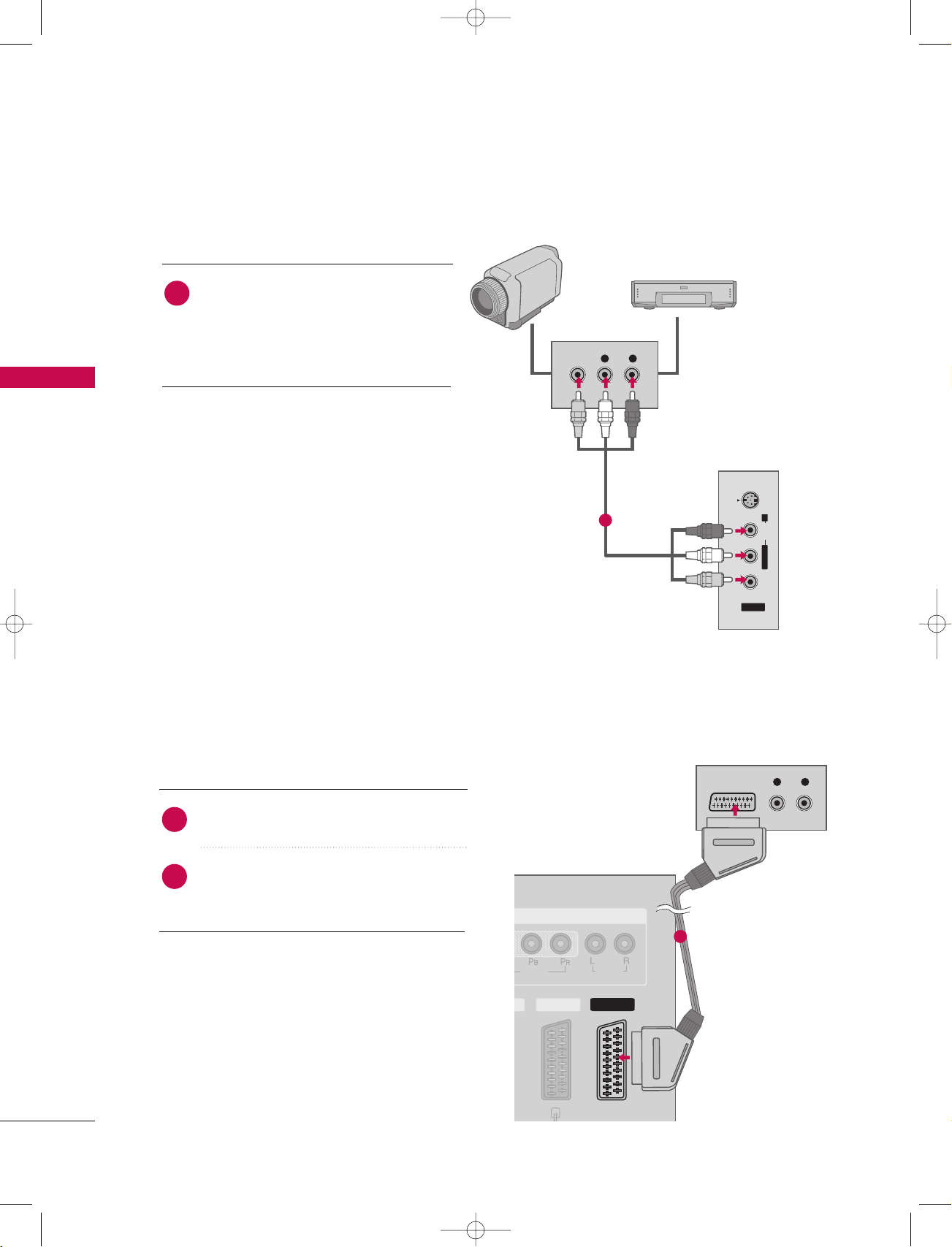
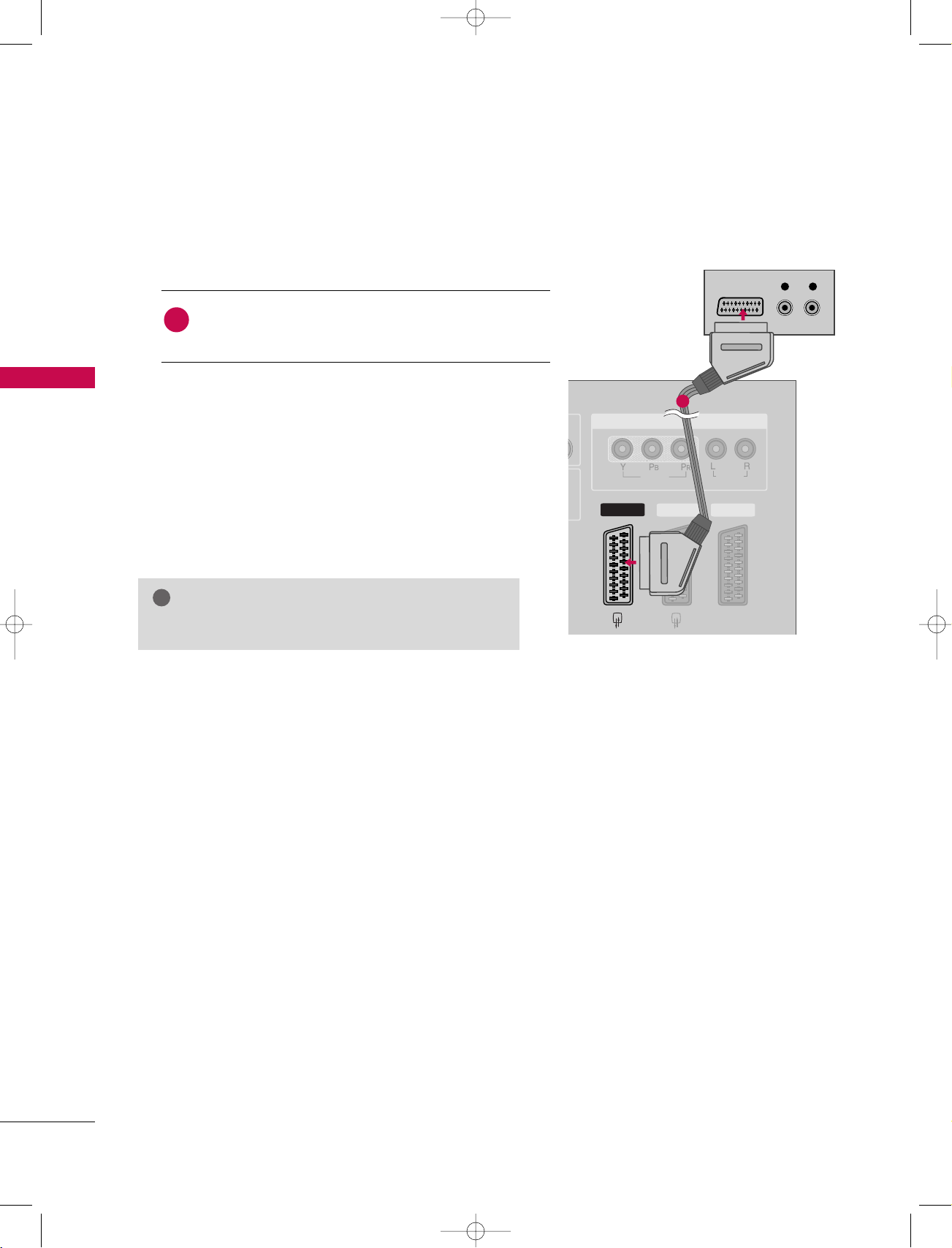
When connecting with a Euro scart
1. How to connect
Connect the Euro scart socket of the VCR to the AV1
1
Euro scart socket on the set.
2. How to use
■
Insert a video tape into the VCR and press PLAY on the
VCR. (Refer to the VCR owner’s manual.
■
■
AA VV 11
Select
input source with using the
the remote control.
If connected to
AA VV 22
, select
AA VV 22
)
II NN PPUUTT
input source.
CONNECTIONS & SETUP
1
button on
NOTE
If the S-VIDEO(Y/C) signal is received through the
GG
Euro scart socket 2 (AV2), you must change to the
SAV2 mode.
Please use the shield scart cable.
GG
15
VIDEO
AUDIO
COMPONENT IN
DTV OUTDTV OUT
L R
VIDEO
/AUDIO
AUDI O
9U1004A_01 06/6/27 2:10 PM Page 16
CONNECTIONS & SETUP
EXTERNAL A/V SOURCE SETUP
1. How to connect
Camcorder
Video Game Set
CONNECTIONS & SETUP
Connect the
1
between TV and external equipment.
Match the jack colors
(
Video = yellow, Audio Left = white, and
Audio Right = red
AAUUDDIIOO/VVIIDDEEOO
.
)
2. How to use
■
■
■
AA VV 44
Select
II NN PPUUTT
If connected to
input source with using the
button on the remote control.
AA VV IINN 33
input, select
input source.
Operate the corresponding external equipment.
PICTURE OUT SETUP
jacks
AA VV 33
VIDEO
L R
S-VIDEOVIDEO AU DIO
1
L/MONO R
AV IN 4
i.e) 32LB1D
16
- The set has a special signal output capability which allows you to hook up a second TV or monitor.
1. How to connect
Connect the second TV or monitor to the
1
TV’s DTV OUT jacks.
See the Operating Manual of the second
2
TV or monitor for further details regarding that device’s input settings.
1
HDMI IN
2
1(DVI)
RS-232C IN
(CONTROL & SERVICE)
AV 1 AV 2 DTV OUT
ANTENNA
OUT
ANTENNA
IN
DIGITAL AUDIO
OUT
OPTICAL
VIDEO
AUDI O
MONO
( )
S-VIDEO
AV IN 3
AV 1AV 1 AV 2 DTV OUT
VARIABLE
AUDIO OUT
!
!
9U1004A_01 06/6/27 2:10 PM Page 17
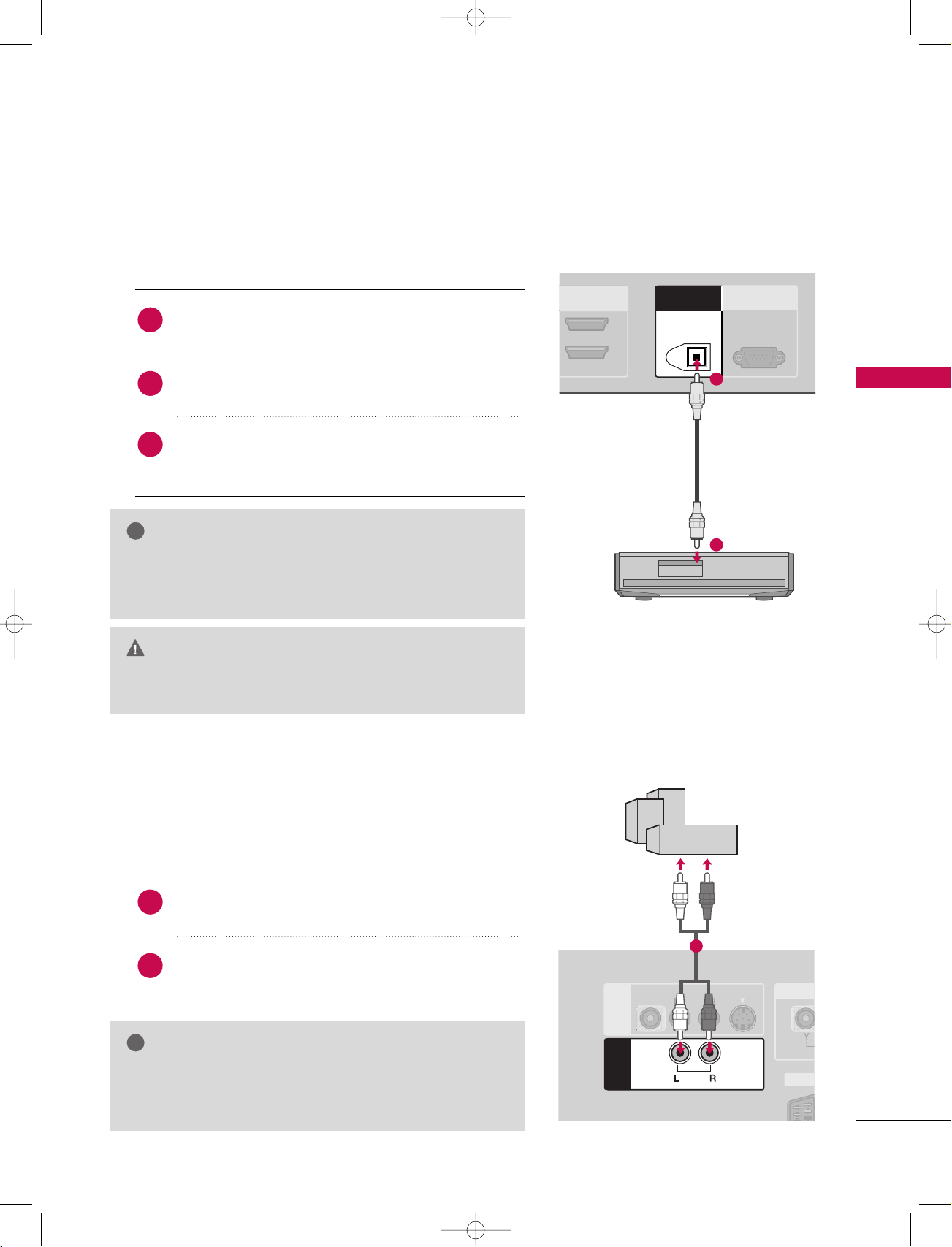
DIGITAL AUDIO OUTPUT
Send the TV’s audio to external audio equipment via the Digital Audio Output (Optical)port.
1. How to connect
Connect one end of an optical cable to the TV Digital
1
Audio (Optical)Output port.
Connect the other end of the optical cable to the
2
digital audio (optical)input on the audio equipment.
Set the “TV Speaker option - Off” in the SOUND
3
menu. (
pp..6699
GG
). See the external audio equipment
instruction manual for operation.
NOTE
When connecting with external audio equipments, such as
GG
amplifiers or speakers, please turn the TV speakers off.
pp..6699
GG
(
)
CAUTION
Do not look into the optical output port. Looking at the
GG
laser beam may damage your vision.
EXTERNAL STEREO
Use to connected either an external amplifier, or add a sub-woofer to
your surround sound system.
1
CONNECTIONS & SETUP
2
1. How to connect
Connect the input jack of the stereo’s amplifier to the
1
VV AARRII AABB LLEE AAUU DDIIOO OOUUTT
GG
Set up your speakers through your analog stereo
2
amplifier, according to the instructions provided with
the amplifier.
NOTE
When connecting with external audio equipments, such as
amplifiers or speakers, please turn the TV speakers off.
pp..6699
GG
(
)
jacks on the set.
1
17
S-VIDEO
AV 1 AV 2 DTV OUT
COMPONENT IN
VIDEO
AUDIO
Y L RPB PR
9U1004A_01 06/6/27 2:10 PM Page 18
CONNECTIONS & SETUP
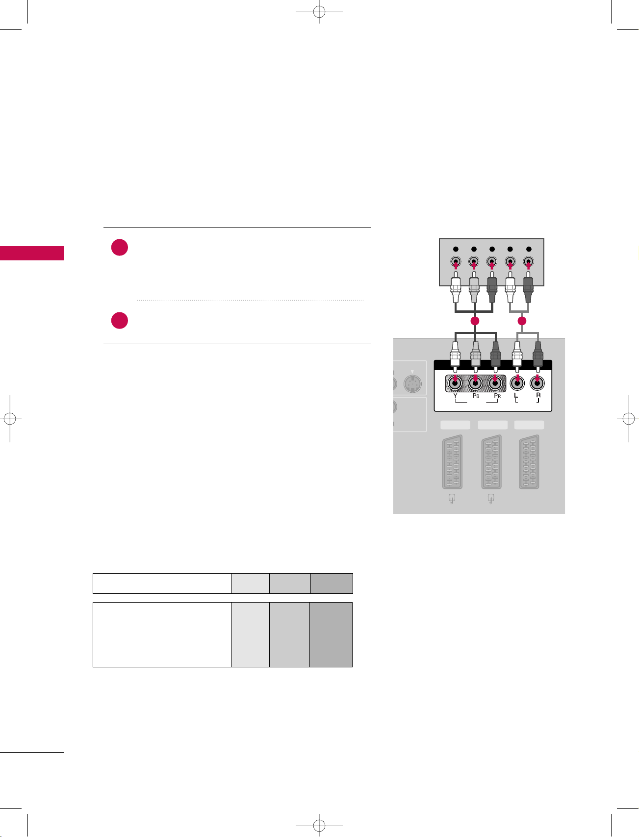
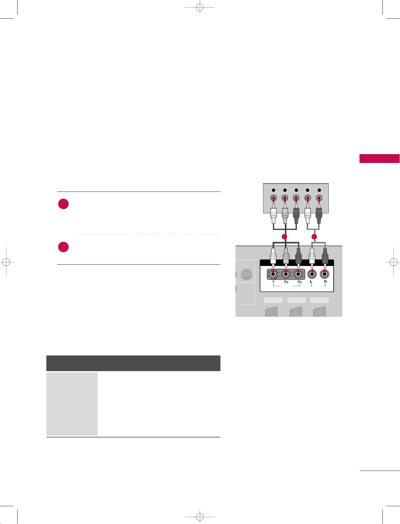
DVD SETUP
When connecting with a Component cable
1. How to connect
Connect the video outputs (Y, P
1
CONNECTIONS & SETUP
CC OOMM PPOONNEENN TT IINN VVIIDDEE OO
the
Match the jack colors
(
Y = green, P
B = blue, and PR = red
)
of the DVD to
B, PR
jacks on the set.
)
.
2. How to use
Component Input ports
To get better picture quality, connect a DVD player to the component input ports as shown below.
Connect the audio outputs of the DVD to the
2
CC OOMM PPOONNEENN TT IINN AAUU DDIIOO
■
Turn on the DVD player, insert a DVD.
■
■
CC OOMM PPOONNEE NNTT
Select
II NN PPUUTT
button on the remote control.
input source with using the
Refer to the DVD player's manual for operating instructions.
Component ports on the TV
jacks on the set.
YPB PR
1 2
Video output ports
18
on DVD player
Y
Y
Y
Y
PB
B-Y
Cb
Pb
P
R-Y
Cr
Pr
R
VIDE
COM
VARIABLE
AUDIO OUT
AV 1 AV 2 DTV OUT
AV IN 3
VIDEO
AUDIO
MONO
( )
S-VIDEO
L R
S-VIDEO
AUDIO
AV 1 AV 2 DTV OUT
ANTENNA
OUT
ANTENNA
IN
DIGITAL AUDIO
OUT
OPTICAL
R
(CON
AV 1 AV 2 DTV OUT
ANTENNA
OUT
ANTENNA
IN
HDMI INHDMI IN
2
1(DVI)
HDMI-DVD OUTPUT
!
9U1004A_01 06/6/27 2:10 PM Page 19
When connecting with an S-Video cable
1. How to connect
Connect the S-VIDEO output of the DVD to the
1
SS --VVII DD EEOO
input on the set.
Connect the audio outputs of the DVD to the
2
input jacks on the set.
2. How to use
■
Turn on the DVD player, insert a DVD.
■
Select
AA VV 33
input source with using the
II NN PPUUTT
button on
the remote control.
■
If connected to
■
Refer to the DVD player's manual for operating instructions.
AA VV IINN 44
, select
AA VV 44
input source.
When connecting with a HDMI cable
1. How to connect
AA UUDD IIOO
12
CONNECTIONS & SETUP
1
2
2. How to use
■
■
If the DVD supports Auto HDMI function, the DVD output
GG
resolution will be automatically set to 1280x720p.
If the DVD does not support Auto HDMI, you need to set
GG
the output resolution appropriately.
To get the best picture quality, adjust the output resolution
of the DVD to 1280x720p.
Connect the HDMI output of the DVD to the
HHDD MMII II NN 11((DD VVII))
or 22jack on the set.
No separated audio connection is necessary.
HHDD MMII11 // DD VVII
Select
II NN PPUUTT
the
Refer to the DVD player's manual for operating instructions.
button on the remote control.
HHDD MMII22
or
input source with using
NOTE
1
19
!
AV 1 AV 2 DTV OUT
VIDEO
AUDIO
COMPONENT IN
AV 2 DTV OUT
AV 1
L R
VIDEO
/AUDIO
AUDIO
9U1004A_01 06/6/27 2:10 PM Page 20
CONNECTIONS & SETUP
When connecting with a Euro scart
1. How to connect
Connect the Euro scart socket of the DVD to the
1
Euro scart socket on the set.
AA VV 11
CONNECTIONS & SETUP
2. How to use
■
Turn on the DVD player, insert a DVD.
■
■
■
Please use the shield scart cable.
GG
Select
AA VV11
input source with using the
II NN PPUUTT
on the remote control.
If connected to
AA VV 22
, select
AA VV 22
input source.
Refer to the DVD player's manual for operating instructions.
NOTE
1
button
20
S-VIDEO
AV 1 AV 2 DTV OUT
COMPONENT IN
VIDEO
AUDIO
Y L RPB PR
9U1004A_01 06/6/27 2:10 PM Page 21
HDSTB SETUP
This TV can receive Digital Over-the-air/Cable signals without an external digital set-top box. However, if you
do receive digital signals from a digital set-top box or other digital external device, refer to the figure as
shown below.
When connecting with a Component cable
1. How to connect
)
Connect the video outputs (Y, PB, PR
1
set-top box to the
CC OOMM PPOONNEENN TT IINN VVIIDDEE OO
on the set. Match the jack colors
(Y = green, P
Connect the audio output of the digital set-top box to
2
CC OOMM PPOONNEENN TT IINN AAUU DDIIOO
the
B = blue, and P
R = red).
2. How to use
■
Turn on the digital set-top box.
(
Refer to the owner’s manual for the digital set-top box.
■
CC OOMM PPOONNEE NNTT
Select
II NN PPUUTT
input source with using the
button on the remote control.
of the digital
jacks
jacks on the set.
)
CONNECTIONS & SETUP
1 2
Signal
480i
576i
480p
576P
720p
10 8 0 i
Component
Yes
Yes
Yes
Yes
Yes
Yes
HDMI1/DVI,
RGB-DTV, HDMI2
No
No
Yes
Yes
Yes
Yes
21
OUT
IN
AV 1 AV 2 DTV OUT
OUT
IN
REMOTE
CONTROL
REMOTE
CONTROL
RGB IN
RGB (PC/DTV)
AUDIO (RGB/DVI)AUDIO (RGB/DVI)
L R
RGB OUTPUT
DIGITAL AUDIO
OUT
OPTICAL
RS
(CONTR
AV 1 AV 2 DTV OUT
ANTENNA
OUT
ANTENNA
IN
HDMI INHDMI IN
2
1(DVI)
HDMI-DVD OUTPUT
!
9U1004A_01 06/6/27 2:10 PM Page 22
CONNECTIONS & SETUP
When connecting with a D-sub 15pin cable
1. How to connect
Connect the RGB output of the digital set-top box to
1
2
CONNECTIONS & SETUP
RR GG BB ((PPCC//DD TTVV
the
Connect the audio outputs of the set-top box to the
AA UUDDIIOO ((RR GG BB//DD VVII
))
jack on the set.
))
jack on the set.
2. How to use
■
Turn on the digital set-top box.
(
■
Select
on the remote control.
When connecting with a HDMI cable
1. How to connect
1
2
2. How to use
■
Turn on the digital set-top box.
(
■
Select
the
Refer to the owner’s manual for the digital set-top box.
RR GGBB
input source with using the
Connect the digital set-top box to
22
or
jack on the set.
II NN PPUUTT
button
HHDD MMII IINN 11 ((DDVVII ))
No separated audio connection is necessary.
Refer to the owner’s manual for the digital set-top box.
II NN PPUUTT
HHDD MMII11 // DD VVII
button on the remote control.
HHDD MMII22
or
input source with using
)
)
1 2
1
22
NOTE
If the digital set-top box supports Auto HDMI function, the
GG
output resolution of the source device will be automatically
set to 1280x720p.
If the digital set-top box player does not support Auto HDMI,
GG
you need to set the output resolution appropriately.
To get the best picture quality, adjust the output resolution of
the source device to 1280x720p.
AV 1 AV 2 DTV OUT
ANTENNA
OUT
ANTENNA
IN
VIDEO
AUDIO
DIGITAL AUDIO
OUT
OPTICAL
RS-232C IN
(CONTROL & SERVICE)
AV 1 AV 2 DTV OUT
ANTENNA
OUT
ANTENNA
IN
OUT
IN
REMOTE
CONTROL
REMOTE
CONTROL
RGB INRGB IN
AUDIO (RGB/DVI)
RGB (PC/DTV)
HDMI INHDMI IN
1(DVI)
DVI-DTV OUTPUT
AUDIO
2
!
9U1004A_01 06/6/27 2:10 PM Page 23
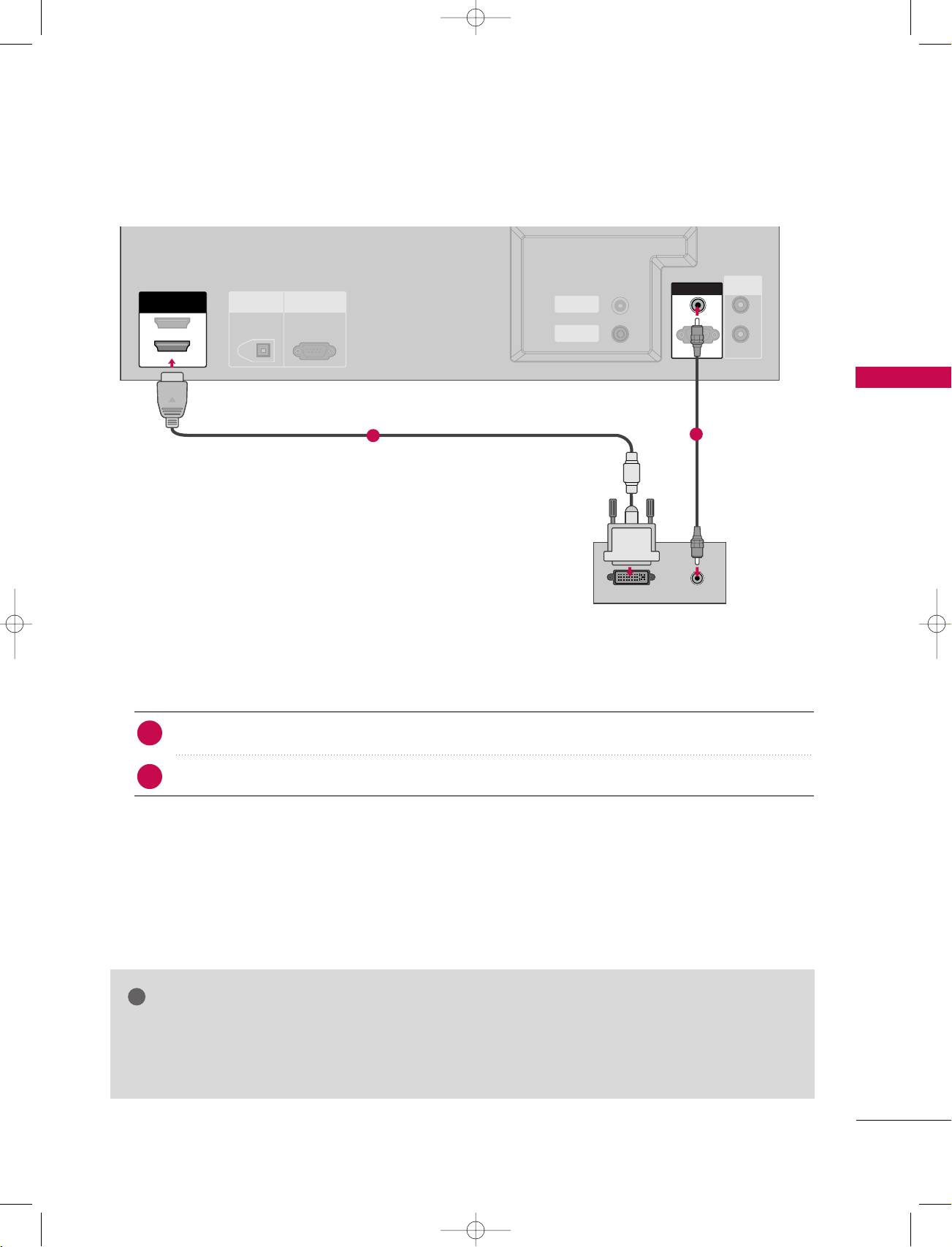
When connecting with a HDMI to DVI cable
1
CONNECTIONS & SETUP
2
1. How to connect
Connect the DVI output of the digital set-top box to the
1
Connect the audio output of the digital set-top box to the
2
HHDD MMII IINN 11((DD VVII))
AA UUDD IIOO((RR GG BB//DD VVII
jack on the set.
2. How to use
■
Turn on the digital set-top box. (Refer to the owner’s manual for the digital set-top box.
■
Select
HHDD MMII11 // DD VVII
input source with using the
II NN PPUUTT
button on the remote control.
NOTE
HDMI2 source does not support DVI source.
GG
If the digital set-top box has a DVI output and no HDMI output, a separated audio connection is
GG
necessary.
))
jack on the set.
)
23
!
AV 1 AV 2 DTV OUT
OUT
IN
REMOTE
CONTROL
REMOTE
CONTROL
ANTENNA
OUT
ANTENNA
IN
RGB IN
RGB (PC/DTV)
AUDIO (RGB/DVI)AUDIO (RGB/DVI)
RGB OUTPUTAUDIO
HDMI IN
1(DVI)
9U1004A_01 06/6/27 2:10 PM Page 24
CONNECTIONS & SETUP
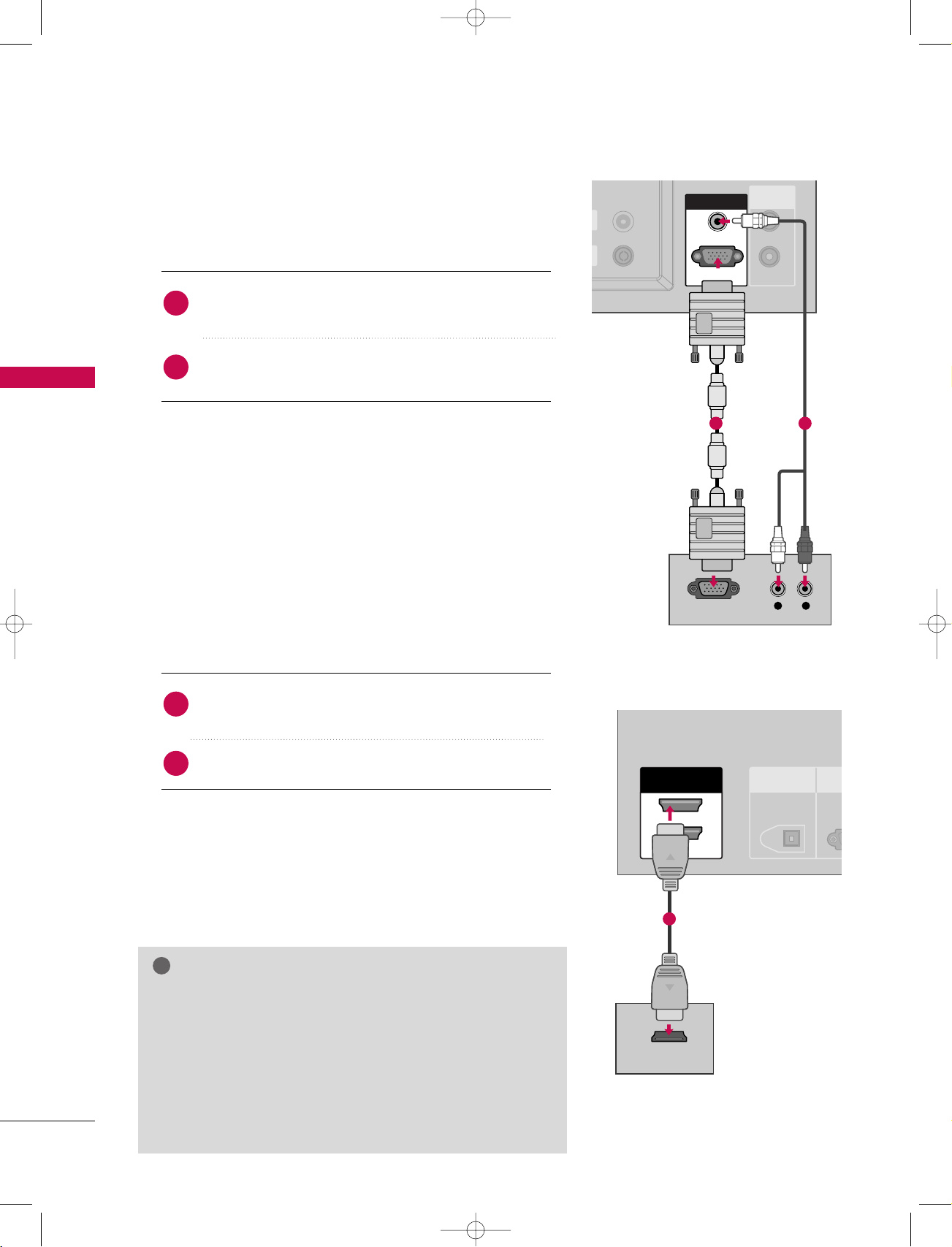
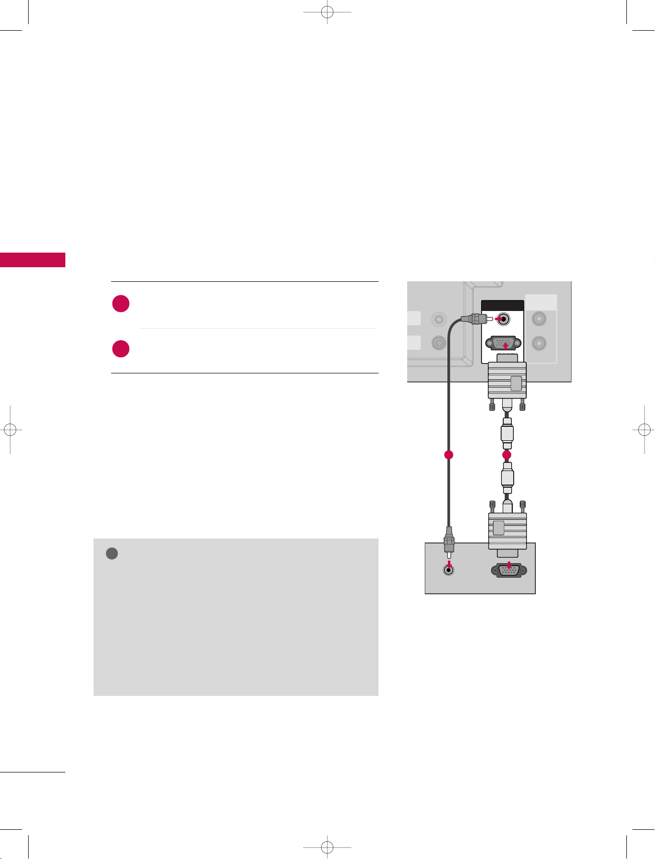
PC SETUP
This TV provides Plug and Play capability, meaning that the PC adjusts automatically to the TV's settings.
When connecting with a D-sub 15pin cable
CONNECTIONS & SETUP
1. How to connect
1
2
2. How to use
■
Turn on the PC and the set.
■
Select RGB input source with using the INPUT button on
the remote control.
NOTE
Check the image on your TV. There may be noise associ-
GG
ated with the resolution, vertical pattern, contrast or
brightness in PC mode. If noise is present, change the PC
output to another resolution, change the refresh rate to
another rate or adjust the brightness and contrast on the
VIDEO menu until the picture is clear. If the refresh rate
of the PC graphic card can not be changed, change the
PC graphic card or consult the manufacturer of the PC
graphic card.
Connect the RGB output of the PC to the
((
PPCC//DD TTVV
Connect the PC audio output to the
((
RR GG BB//DD VVII
))
jack on the set.
))
jack on the set.
AA UUDD IIOO
RR GGBB
12
24
!
DIGITAL AUDIO
OUT
OPTICAL
RS-232C IN
(CONTROL & SERVICE)
AV 1 AV 2 DTV OUT
ANTENNA
OUT
ANTENNA
IN
OUT
IN
REMOTE
CONTROL
REMOTE
CONTROL
RGB IN
AUDIO (RGB/DVI)AUDIO (RGB/DVI)
RGB (PC/DTV)
HDMI IN
1(DVI)
DVI-PC OUTPUT
AUDIO
2
9U1004A_01 06/6/27 2:10 PM Page 25
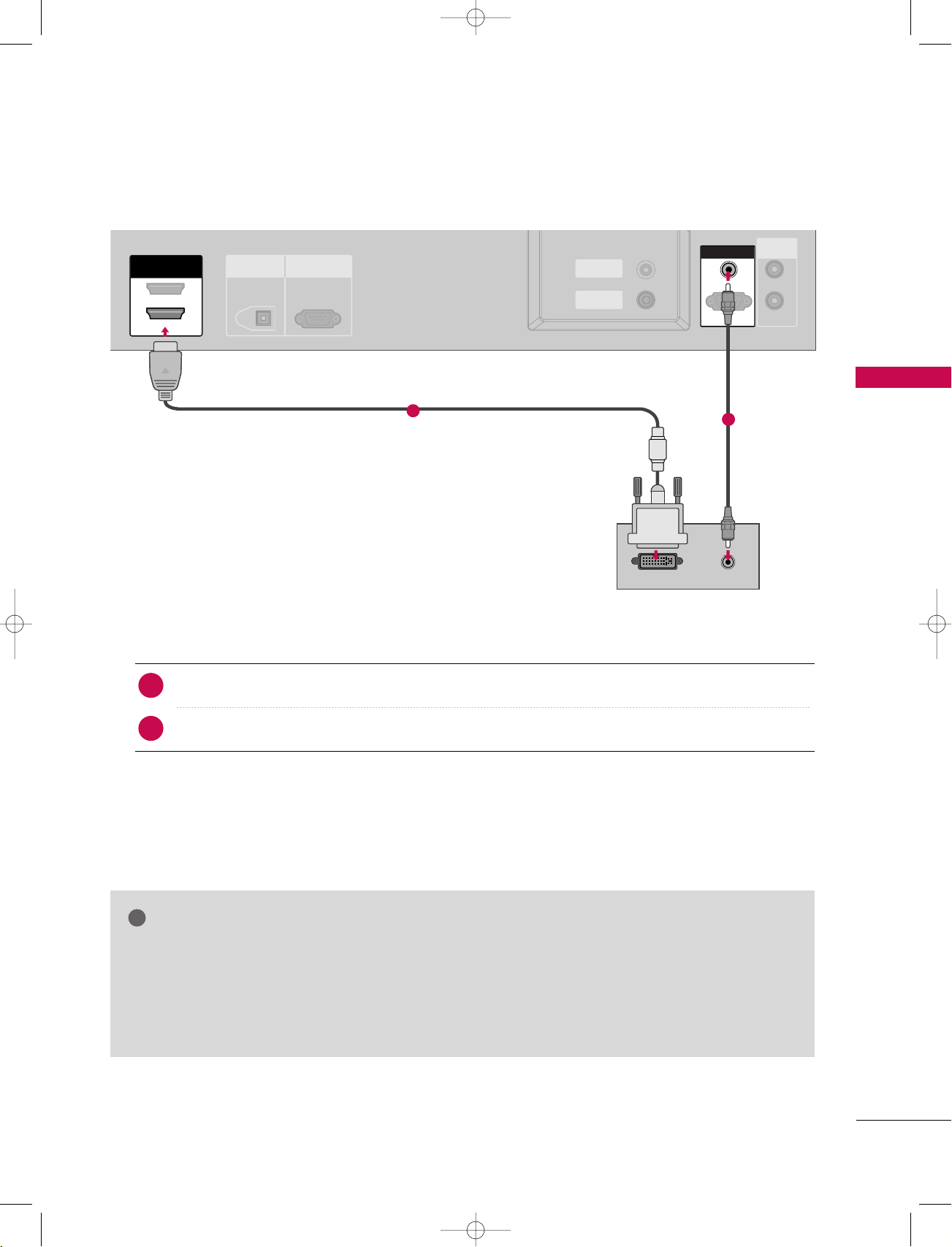
When connecting with a HDMI to DVI cable
1. How to connect
Connect the DVI output of the PC to the
1
Connect the PC audio output to the
2
2. How to use
1
HHDD MMII II NN 11((DD VVII))
AA UUDDIIOO ((RR GG BB//DD VVII
jack on the set.
))
jack on the set.
CONNECTIONS & SETUP
2
■
Turn on the PC and the set
■
HDMI2 source does not support DVI source.
GG
If the PC has a DVI output and no HDMI output, a separated audio connection is necessary.
GG
If the PC does not support Auto DVI, you need to set the output resolution appropriately. To get the
GG
Select
NOTE
HHDD MMII11 // DD VVII
input source with using the
II NN PPUUTT
button on the remote control.
best picture quality, adjust the output resolution of PC graphics card's output resolution to 1024x768,
60Hz.
25
!
!
9U1004A_01 06/6/27 2:10 PM Page 26
CONNECTIONS & SETUP
NOTE
CONNECTIONS & SETUP
Avoid keeping a fixed image on the set’s screen for
G
a long period of time. The fixed image may become
permanently imprinted on the screen; use a screen
saver when possible.
The synchronization input waveform for Horizontal
G
and Vertical frequencies are separate.
If the resolution of PC is over UXGA, there will be
G
no picture on the set.
This set uses a VESA Plug and Play Solution. The
G
set provides EDID data to the PC system with a
DDC protocol. The PC adjusts automatically when
using this set.
DDC protocol is preset for RGB (Analog RGB),
G
HDMI (Digital RGB) mode.
If required, adjust the settings for Plug and Play
G
functionally.
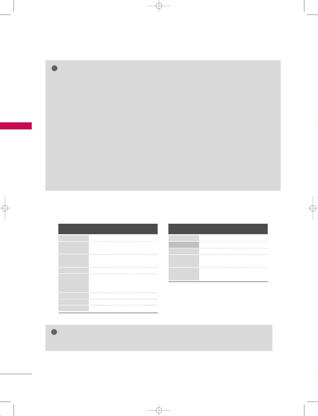
Supported Display Resolution
RGB[PC] / HDMI[PC] mode
Resolution
720x400
640x480
800x600
832x624
1024x768
1280x768
1360x768
1366x768
Horizontal
Frequency(KHz)
31 . 4 6 8
31 . 4 6 9
37.684
37.879
46. 875
49.725
48.363
56.47
60.123
47.776
47.720
47.720
Vertical
Frequency(Hz)
70. 8
59.94
75.00
60.31
75
74 . 55
60
70
75.029
59.870
59.799
59.799
If graphic card on the PC does not output analog
G
and digital RGB simultaneously, connect only one
of either RGB (PC/DTV) or HDMI IN (or
HDMI/DVI IN to display the PC on the set.
If graphic card on the PC does output analog and
G
digital RGB simultaneously, set the set to either
RGB or HDMI; (the other mode is set to Plug and
Play automatically by the set.)
DOS mode may not work depending on video card
G
if you use a HDMI to DVI cable.
When you use too long RGB-PC cable, there might
G
be a noise on the screen. We recommend using
under 5m of the cable. It provides the best picture
quality.
RGB[DTV] / HDMI[DTV] mode
Resolution
720x576
640x480
720x480
1280x720
1920x1080
Horizontal
Frequency(KHz)
31 . 2 5
31 . 5
31 . 4 7
45.00
44.96
28. 13
33 .72
Vertical
Frequency(Hz)
50.00
59.94/60
59.94/60
50.00
59.94/60
50.00
59.94/60
NOTE
The set is supported to 640x480 in HDMI[DTV] mode.
GG
26
D/A TV
INPUT
LIST
Q.VIEW
PRVO L
POWER
1 2 3
4 5 6
7809
GUIDE
PIP PR-
PIP
MENU
FAV
MUTE
EXIT
VCR
TV
DVD
ARC
TEXT
SWAP
BACK
PIP PR+
INFO
i
OK
PIP INPUT
SLEEP
SUBTITLE/
9U1004A_02 06/6/27 2:11 PM Page 27
BASIC OPERATION
TURNING ON THE SET
Connect power cord correctly, the set is switched to
1
standby mode.
2
Press the
press the POWER, INPUT, D/A TV, PR
rr // II
, INPUT or PR
button on the set or
DD EE
DD EE
or NUMBER
buttons on the remote control and then the set will switch
on.
Initializing setup
If the OSD (On Screen Display) is displayed
CHANNEL
Welcome
Before starting, be sure
that TV antenna is
connected.
OK
on the screen as figure after turning on the
set, you can adjust the Auto Programme
tuning.
Note: It will automatically disappear after
approx. 40 seconds unless a button is
pressed.
BASIC OPERATION
27
VOL PR
LIST
Q.VIEW
1 2 3
4 5 6
7809
MENU
MUTE FAV
EXIT
TEXT
OK
VOL
PR
INDEX
POSITION
SIZE
REVEAL
I/II
TIME
MUTE FAV
?
i
LIST
Q.VIEW
1 2 3
4 5 6
7809
9U1004A_02 06/6/27 2:11 PM Page 28
BASIC OPERATION
PROGRAMME SELECTION
BASIC OPERATION
Press the PR
1
programme number.
DD EE
NNUUMMBBEERR
or
buttons to select a
VOLUME ADJUSTMENT
Adjust the volume to suit your personal preference.
Press the
1
If you want to switch the sound off, press the
VV OOLL
button to adjust the volume.
DD EE
MM UUTTEE
button.
28
You can cancel this function by pressing the
VV OOLL
DD EE
, or
II // II II
button.
MM UUTTEE
,
 Loading...