

Page 1
Owner's Manual
IPS LED MONITOR
(LED MONITOR*)
*LG LED Monitors are LCD Monitors with LED Backlighting.
Please read the safety information carefully before using the product.
IPS LED Monitor (LED Monitor) Model List
29WK500
34WK500
www.lg.com
Page 2

2
Contents
ENGLISH
ENG
CONTENTS
3 LICENSE
4 ASSEMBLING AND PREPARING
4 Product Components
5 Supported Drivers and Software
6 Component and Button Description
6 - How to Use the Joystick Button
7 Input Connector
8 Moving and Lifting the Monitor
9 Installing the Monitor
9 - Assembling the stand base
10 Installing the Monitor
10 - Assembling the stand base
12 - Installing onto a table
13 - Adjusting the angle
15 - Using the Kensington lock
16 - Detaching the Stand Body
16 - Installing the wall mount plate
16 - Installing to a wall
20 USER SETTINGS
20 Activating the Main Menu
20 - Main Menu Features
21 User Settings
21 - Menu Settings
25 TROUBLESHOOTING
27 SPECIFICATIONS
27 29WK500
29 34WK500
30 Factory Support Mode (Preset Mode, PC)
30 HDMI
30 HDMI Timing (Video)
31 Power LED
18 USING THE MONITOR
18 Connecting to a PC
18 - HDMI connection
18 Connecting to AV Devices
18 - HDMI connection
19 Connecting to External Devices
19 - Connecting Headphones
Page 3

LICENSE
3
LICENSE
Each model has different licenses. Visit www.lg.com for more information on the license.
The terms HDMI and HDMI High-Definition Multimedia Interface, and the HDMI Logo
are trademarks or registered trademarks of HDMI Licensing Administrator, Inc. in the
United States and other countries.
ENGLISH
ENG
The following content is only applied to the monitor which is sold in Europe market and which needs to meet the ErP
Directive:
* This monitor is set to be turned off automatically after 4 hours when you turn on the display and there is are no adjustments made to the display.
* To make this setting be disabled, change the option to ‘Off’ in OSD menu of “Automatic Standby”.
Page 4

ENGLISH
ENG
ASSEMBLING AND PREPARING
4
ASSEMBLING AND PREPARING
Product Components
Please check whether all the components are included in the box before using the product. If there are missing components, contact the retail store where you purchased the product. Note that the product and components may look
different from those shown here.
or
CD(Owner's Manual) /
Card
HDMI Cable
29WK500
Stand Body
34WK500
Stand Body
Power Cord
( Depending on the country )
Stand Base
Stand Base
AC-DC Adapter
Screw Cover
AC-DC Adapter
( Depending on the country )
2 Screws
CAUTION
Always use genuine components to ensure safety and product performance.
y
The product warranty will not cover damage or injury caused by the use of counterfeit components.
y
It is recommend that use the supplied components.
y
If you use generic cables not certified by LG, the screen may not display or there may be image noises.
y
NOTE
Note that the components may look different from those shown here.
y
Without prior notice, all information and specifications in this manual are subject to change to improve the
y
performance of the product.
To purchase optional accessories, visit an electronics store or online shopping site or contact the retail store
y
where you purchased the product.
Page 5

ASSEMBLING AND PREPARING
Supported Drivers and Software
Check the drivers and software supported by your product and refer to the manuals on the CD enclosed in the product
package.
Drivers and Software Installation Priority 29WK500/34WK500
Monitor Driver Recommended O
OnScreen Control Recommended O
Dual Controller Optional O
Required and Recommended: You can download and install the latest version from the enclosed CD or from the
y
LGE website (www.lg.com).
Optional: You can download and install the latest version from the LGE website (www.lg.com).
y
5
ENGLISH
ENG
Page 6

ENGLISH
ENG
ASSEMBLING AND PREPARING
6
Component and Button Description
29WK500
34WK500
Joystick Button
Power LED
On: power is on
y
Off: power is off
y
How to Use the Joystick Button
You can easily control the functions of the monitor by pressing the joystick button or moving it left/right with your
finger.
Basic Functions
Press the joystick button once with your finger to turn on the
monitor.
Press and hold the joystick button once with your finger to turn off the
monitor.
You can control the volume by moving the joystick button left/right.
◄/►
Power on
Power off
Volume
Control
NOTE
The joystick button is located at the bottom of the monitor.
y
Page 7
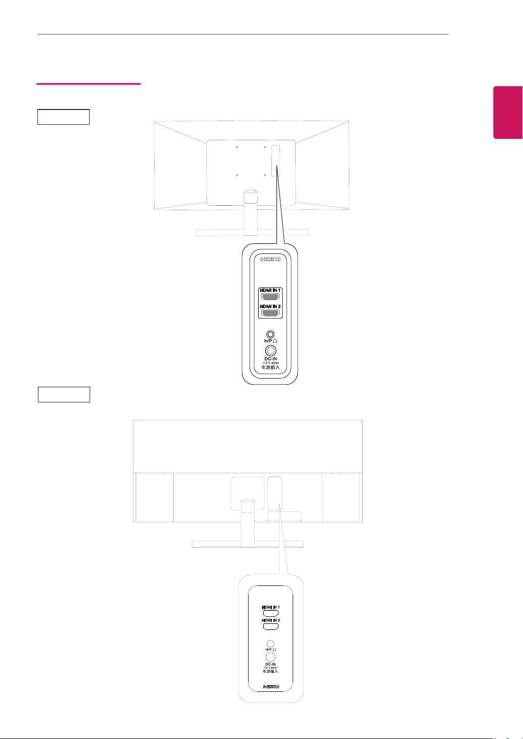
Input Connector
29WK500
ASSEMBLING AND PREPARING
7
ENGLISH
ENG
34WK500
Page 8
ASSEMBLING AND PREPARING
29WK500
34WK500
8
ENGLISH
ENG
Moving and Lifting the Monitor
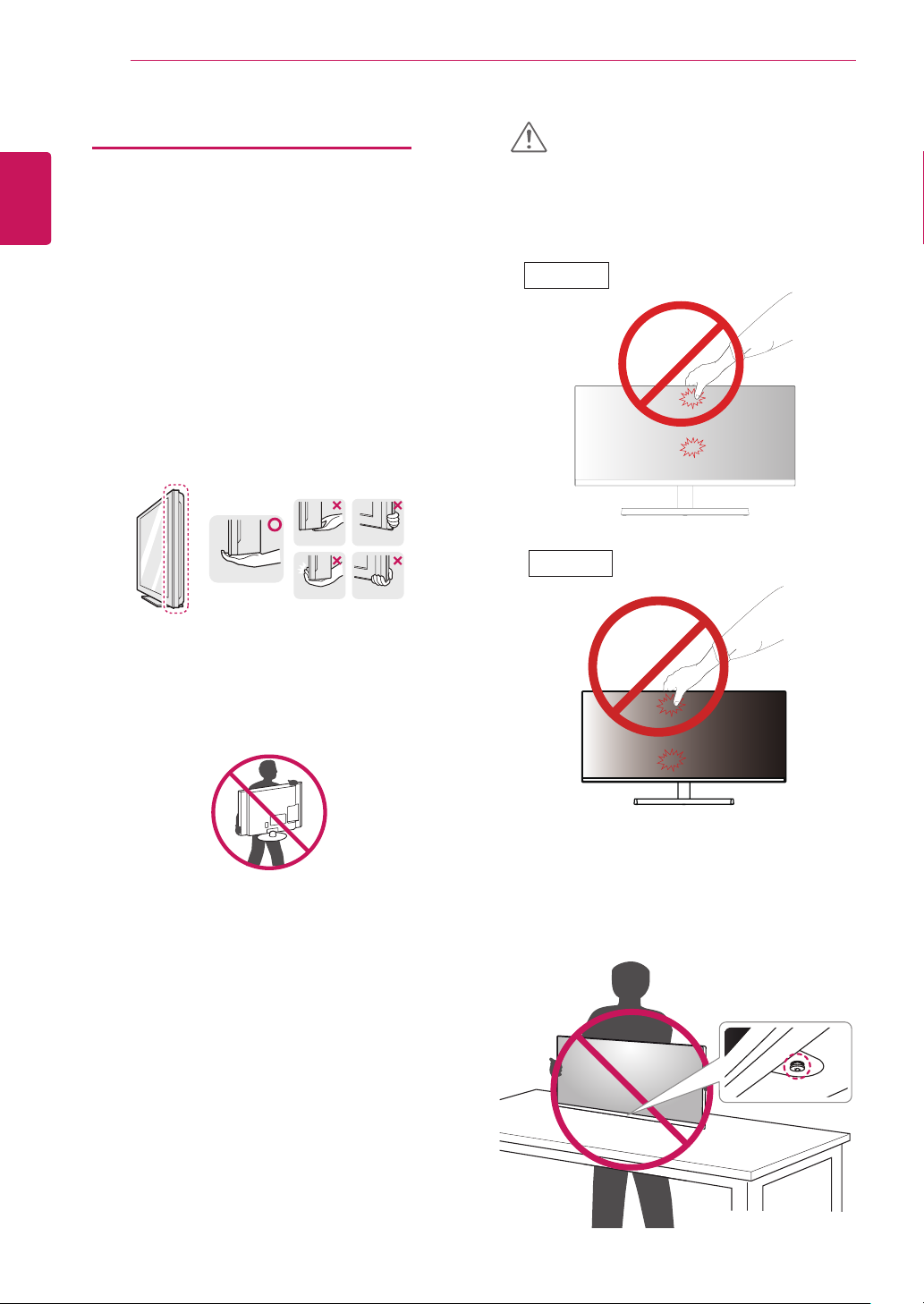
When moving or lifting the monitor, follow these instructions to prevent the monitor from being scratched
or damaged and to ensure safe transportation regardless of its shape or size.
It is advisable to place the monitor in the original
y
box or packing material before attempting to
move it.
Before moving or lifting the monitor, disconnect
y
the power cord and all cables.
Hold the top and bottom of the monitor frame
y
firmly. Do not hold the screen itself.
CAUTION
As far as possible, avoid touching the monitor
y
screen. This may result in damage to the screen or
some of the pixels used to create images.
29WK500
34WK500
When holding the monitor, the screen should face
y
away from you to prevent it being scratched.
When moving the monitor, avoid any strong shock
y
or vibrations to the product.
When moving the monitor, keep it upright, never
y
turn the monitor on its side or tilt it sideways.
If you use the monitor panel without the stand
y
base, its joystick button may cause the monitor to
become unstable and fall, resulting in damage to
the monitor or human injury. In addition, this may
cause the joystick button to malfunction.
Page 9
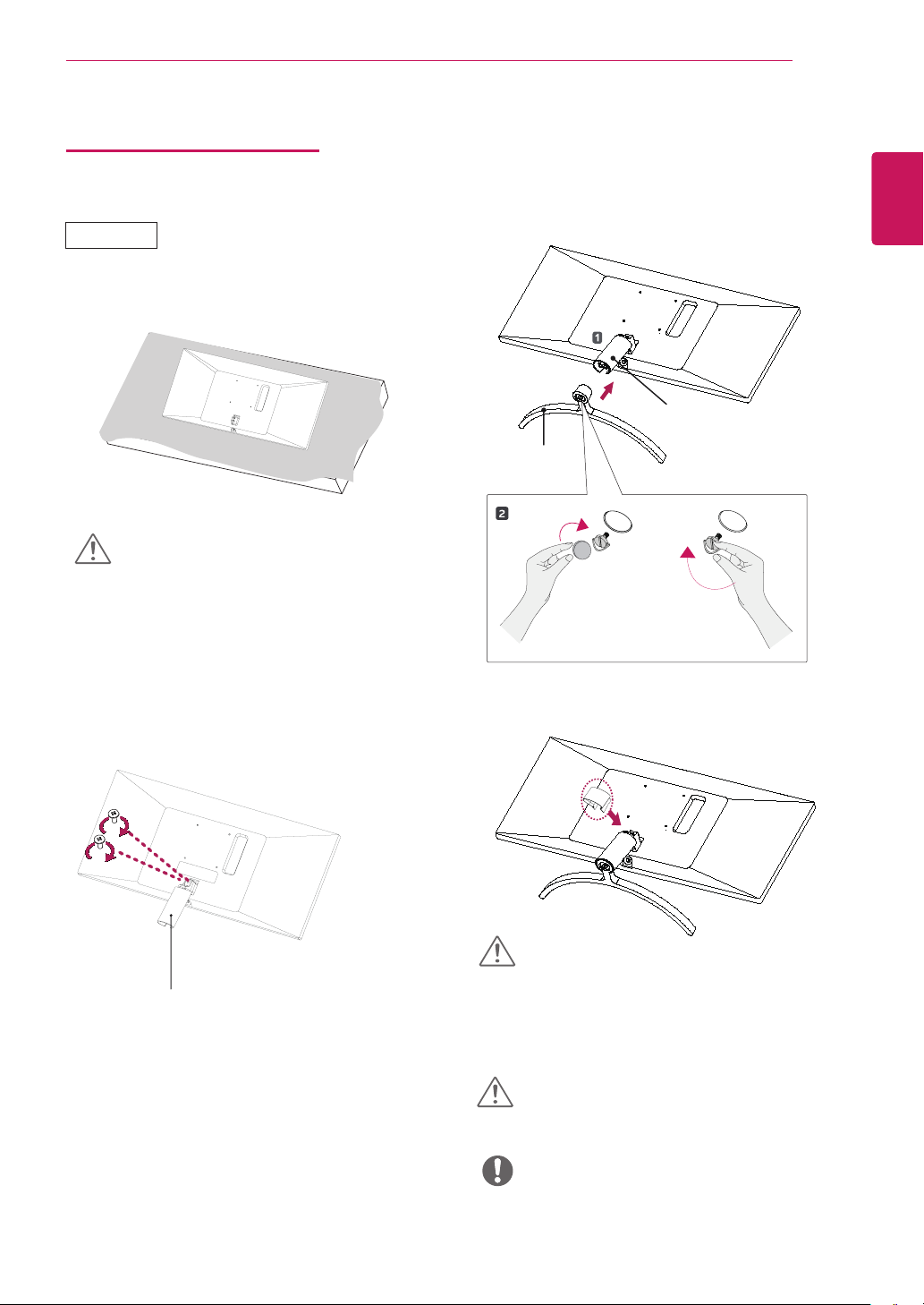
Installing the Monitor
Assembling the stand base
29WK500
1
CAUTION
3
Stand Base
ASSEMBLING AND PREPARING
Stand Body
9
ENGLISH
ENG
To protect the screen from scratches, cover the
y
surface with a soft cloth.
2
Stand Body
or
4
CAUTION
Applying excessive force when tightening the
screws may cause damage to the monitor. Damage caused in this way will not be covered by the
product warranty.
CAUTION
It may hurt your foot off the stand, so be careful.
NOTE
You can disassemble the stand in the reverse
y
order of the assembly.
Page 10
ENGLISH
ENG
ASSEMBLING AND PREPARING
10
Installing the Monitor
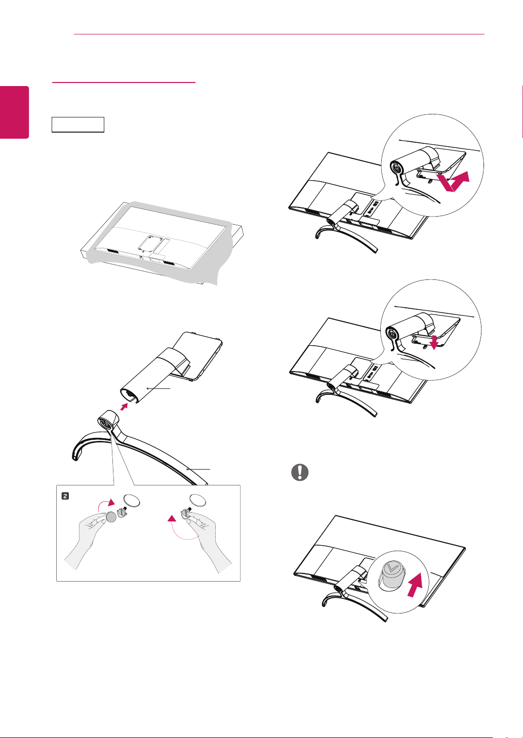
Assembling the stand base
34WK500
1
3
4
2
Stand Body
Stand Base
or
NOTE
Press the stand until the button reaches the top.
y
Page 11
ASSEMBLING AND PREPARING
11
CAUTION
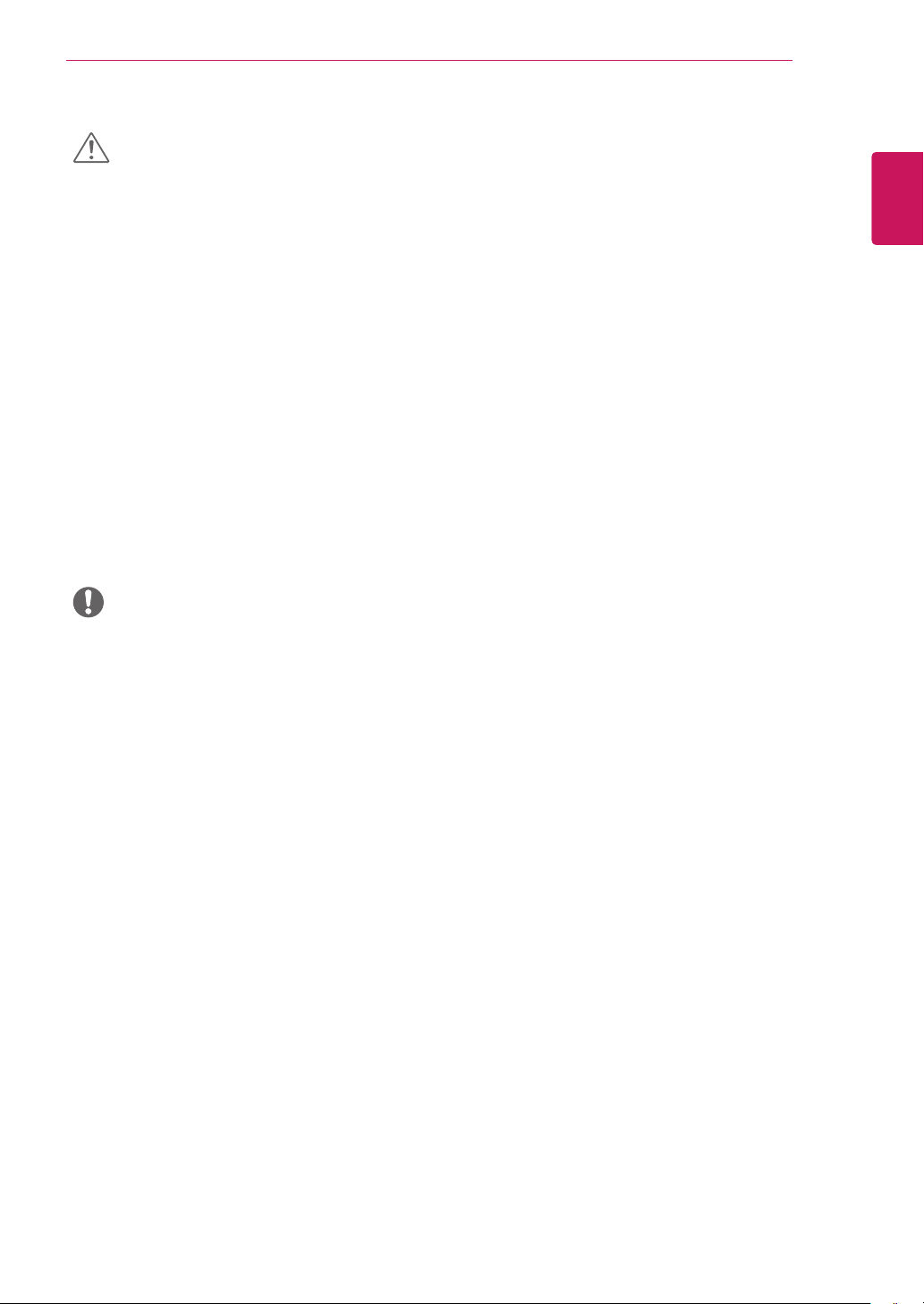
Illustrations in this document represent typical
y
procedures, so they may look different from the
actual product.
Do not carry the monitor upside down by just
y
holding the stand base. This may cause the
monitor to fall off the stand and could result in
personal injury.
When lifting or moving the monitor, do not
y
touch the monitor screen. The force applied to
the monitor screen may cause damage to it.
Do not apply foreign substances (oils, lubricants,
y
etc.) to the screw parts when assembling the
product. (Doing so may damage the product.)
Applying excessive force when tightening screws
y
may cause damage to the monitor. Damage
caused in this way will not be covered by the
product warranty.
NOTE
You can disassemble the stand in the reverse
y
order of the assembly.
ENGLISH
ENG
Page 12
ENGLISH
ENG
ASSEMBLING AND PREPARING
12
Installing onto a table
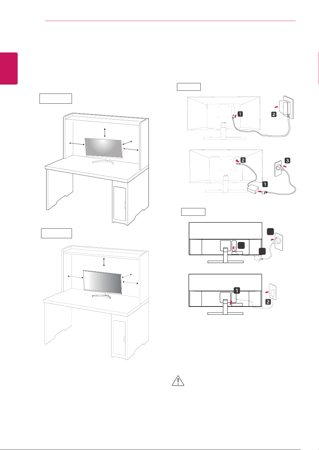
Lift the monitor and place it on the table in an up-
1
right position.
Place at least 100 mm away from the wall to ensure
sufficient ventilation.
29WK500
Connect the Power cord to the monitor, then plug
2
the power cord into the wall outlet.
29WK500
34WK500
100 mm
100 mm
100 mm
100 mm
100 mm
100 mm
100 mm
100 mm
or
34WK500
3
2
1
or
Press the joystick button on the bottom of the
3
monitor to turn on the monitor.
CAUTION
Unplug the power cord prior to moving or install-
y
ing the monitor. There is risk of electric shock.
Page 13
ASSEMBLING AND PREPARING
13
Cautions When Connecting Power Cord
100-240 V~
Make sure to use the power cord that is pro-
y
vided in the product package and connect it to a
grounded power outlet.
If you need another power cord, please contact
y
your local dealer or the nearest retail store.
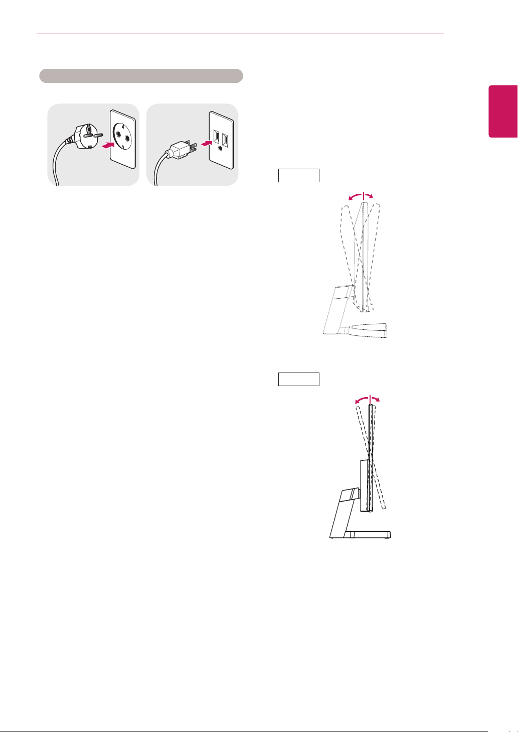
Adjusting the angle
Place the monitor in an upright position, mounted
1
on the stand base.
Adjust the angle of the screen. The angle of the
2
screen can be adjusted forwards or backwards for a
comfortable viewing experience.
29WK500
15° -5°
Rear Side
Front Side
ENGLISH
ENG
34WK500
Rear Side
15° -5°
Front Side
Page 14
ASSEMBLING AND PREPARING
14
ENGLISH
ENG
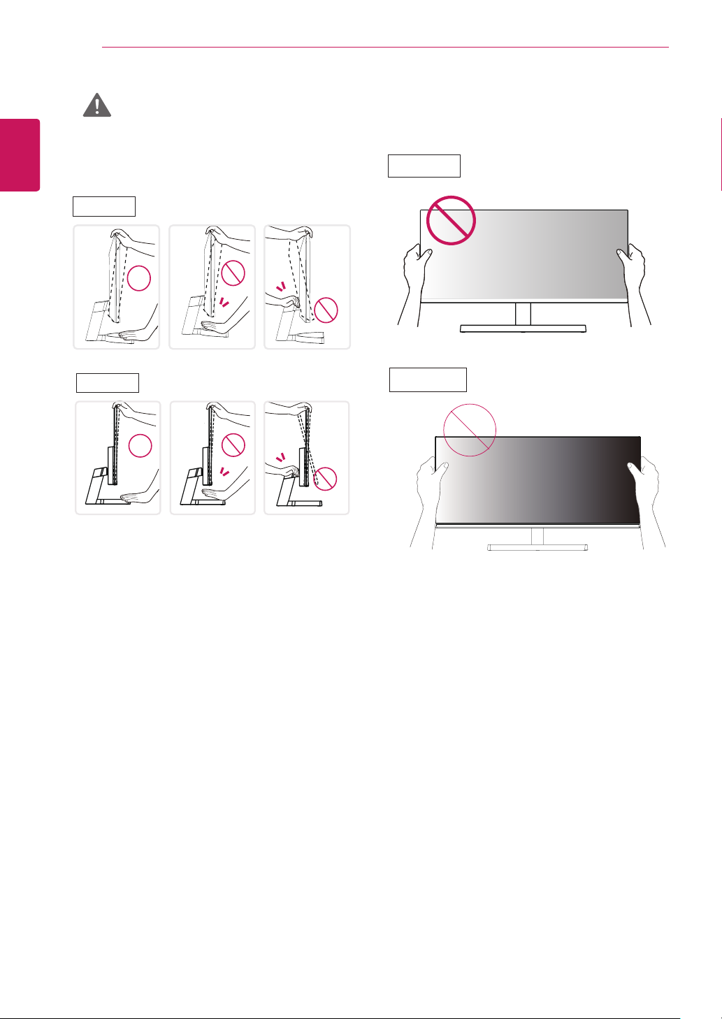
WARNING
To avoid injury to the fingers when adjusting the
y
screen, do not hold the lower part of the monitor's frame as illustrated below.
29WK500
34WK500
Be careful not to touch or press the screen area
y
when adjusting the angle of the monitor.
29WK500
34WK500
Page 15
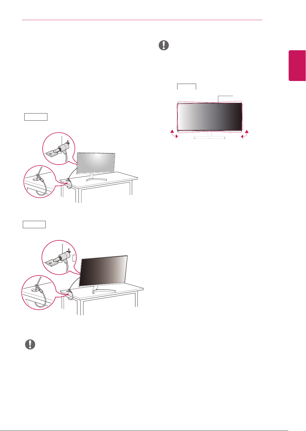
Using the Kensington lock
29WK500
The Kensington security system connector is located at
the back of the Monitor set.
For more information on installation and usage, refer to
the Kensington lock user manual or visit the website at
http://www.kensington.com.
Connect the Kensington security system cable between
the Monitor set and a table.
29WK500
ASSEMBLING AND PREPARING
NOTE
The left or right side of the monitor head can be
y
slightly rotated up or down (up to 3°). Adjust the
horizontal level of the monitor head.
34WK500
Monitor head
15
ENGLISH
ENG
34WK500
NOTE
Use of the Kensington lock is optional.
y
The accessories can be purchased at your local
electronics store.
Page 16
ASSEMBLING AND PREPARING
16
ENGLISH
ENG
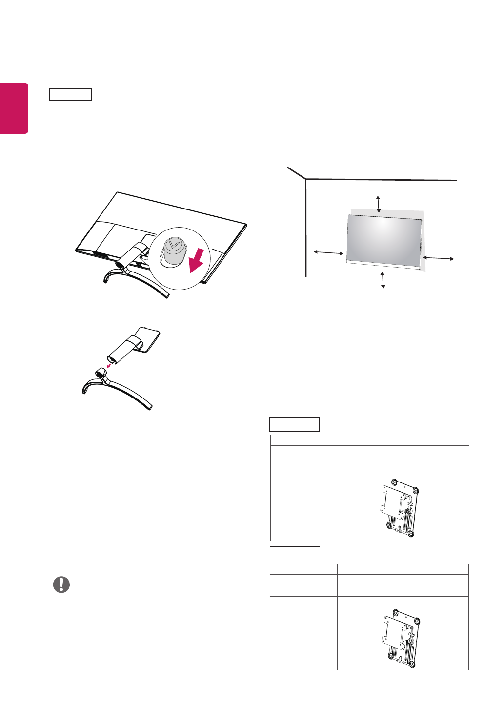
Detaching the Stand Body
34WK500
Place the monitor’s screen face down. To protect the
1
screen from scratches, cover the surface with a soft
cloth.
Remove the stand from the monitor by pressing
2
the button on the bottom center of the back of the
monitor.
Installing to a wall
Install the monitor at least 100 mm away from the wall
and leave about 100 mm of space at each side of the
monitor to ensure sufficient ventilation. Detailed installation instructions can be obtained from your local retail
store. Please refer to the manual to install and set up a
tilting wall mounting bracket.
100 mm
100 mm
100 mm
To install the monitor to a wall, attach a wall mounting
bracket (optional) to the back of the monitor.
Make sure that the wall mounting bracket is securely fixed
to the monitor and to the wall.
1 If you use screw longer than standard, the monitor
might be damaged internally.
2 If you use improper screw, the product might be dam-
aged and drop from mounted position.
In this case, LG Electronics is not responsible for it.
100 mm
Installing the wall mount plate
This monitor supports the specification of the standard
wall mount plate or compatible device.
Place the screen face down. To protect the screen
1
from scratches, cover the surface with a soft cloth.
Place the wall mount plate onto the monitor and
2
align it with the screw holes.
Tighten the four screws to fix the plate to the moni-
3
tor using a screwdriver.
NOTE
The wall mount plate is sold separately.
y
For more information on installation, refer to the
y
wall mount plate's installation guide.
Be careful not to use excessive force when
y
mounting the wall mount plate, as this can damage the monitor's screen.
29WK500
Wall Mount (A x B) 100 × 100
Standard screw M4 x L10
Number of screws 4
Wall Mount Plate
(Optional)
RW120
34WK500
Wall Mount (A x B) 100 x 100
Standard screw M4 x L10
Number of screws 4
Wall Mount Plate
(Optional)
RW120
Page 17
ASSEMBLING AND PREPARING
17
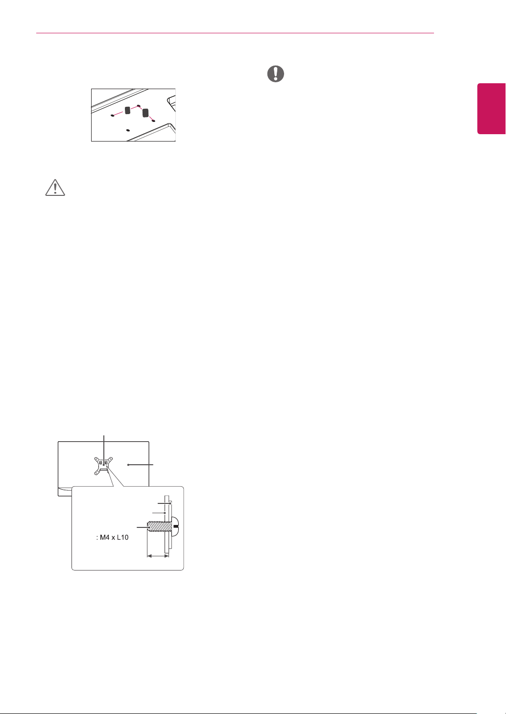
Wall Mount (A x B)
y
A
B
CAUTION
Unplug the power cord before moving or install-
y
ing the monitor to avoid electric shocks.
Installing the monitor on the ceiling or on a
y
slanted wall may result in the monitor falling off,
which could lead to injury. Please use the genuine LG wall mounting bracket. For more information, contact your local retail store or a qualified
installer.
Applying excessive force when fastening screws
y
may cause damage to the monitor. Damage
caused in this way will not be covered by the
product warranty.
Use the wall mounting bracket and screws
y
that conform to the VESA standard. Damage
caused by the use or misuse of inappropriate
components will not be covered by the product
warranty.
Screw length from outer surface of back cover
y
should be under 8mm.
Wall mount Pad
NOTE
Use the screws specified by the VESA standard.
y
The wall mount kit includes the installation guide
y
and all necessary parts.
The wall mounting bracket is optional. The acces-
y
sories can be purchased at your local retail store.
The length of the screw may differ for each wall
y
mounting bracket. Ensure the correct length
screw is used.
For more information, please refer to the user
y
manual for the wall mounting bracket.
ENGLISH
ENG
Wall mount Pad
Back Cover
Standard screw
Back Cover
Max.8mm
Page 18
USING THE MONITOR
18
ENGLISH
ENG
USING THE MONITOR
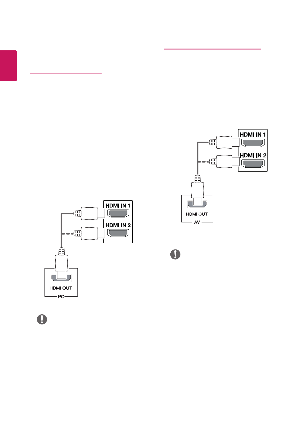
Connecting to a PC
This monitor supports the *Plug and Play feature.
y
*Plug and Play: A feature that allows you to add
a device to your computer without having to
reconfigure anything or install any manual drivers.
HDMI connection
Transmits the digital video and audio signals from your
PC and A/V devices to the monitor. Connect your PC
and AV device to the monitor with the HDMI cable as
illustrated below.
Press the menu button and then select the input option
from the input menu.
Connecting to AV Devices
HDMI connection
Transmits the digital video and audio signals from your
PC and A/V devices to the monitor. Connect your PC
and AV device to the monitor with the HDMI cable as
illustrated below.
Press the menu button and then select the input option
from the input menu.
NOTE
If you use HDMI PC, it can cause compatibility
y
problem.
Use a certified cable with the HDMI logo attached.
y
If you do not use a certified HDMI cable, the
screen may not display or a connection error may
occur.
Recommended HDMI cable types
y
- High-Speed HDMI®/TM Cable
- High-Speed HDMI®/TM Cable with Ethernet
NOTE
Use a certified cable with the HDMI logo attached.
y
If you do not use a certified HDMI cable, the
screen may not display or a connection error may
occur.
Recommended HDMI cable types
y
- High-Speed HDMI®/TM Cable
- High-Speed HDMI®/TM Cable with Ethernet
Page 19
Connecting to External Devices
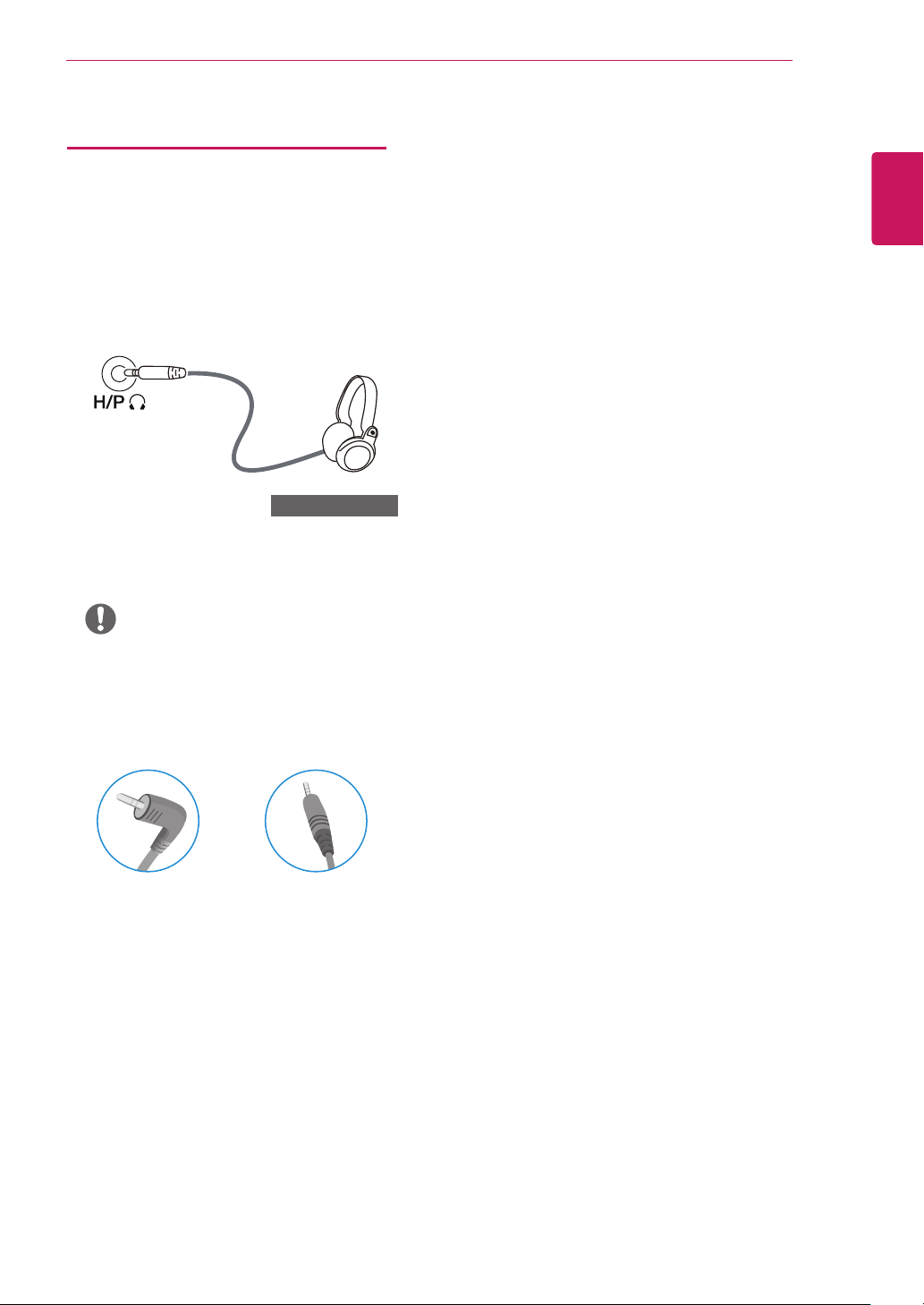
Connecting Headphones
Connect peripherals to the monitor via the headphones
port. Connect as illustrated.
(sold separately)
USING THE MONITOR
19
ENGLISH
ENG
NOTE
Peripheral devices are sold separately.
y
If you use angled earphones, it may cause a prob-
y
lem with connecting another external device to
the monitor. Therefore, it is recommended to use
straight earphones.
Angled Straight
Depending on the audio settings of the PC and
y
external device, headphones and speaker functions
may be limited.
Page 20
20
User Settings
ENGLISH
ENG
USER SETTINGS
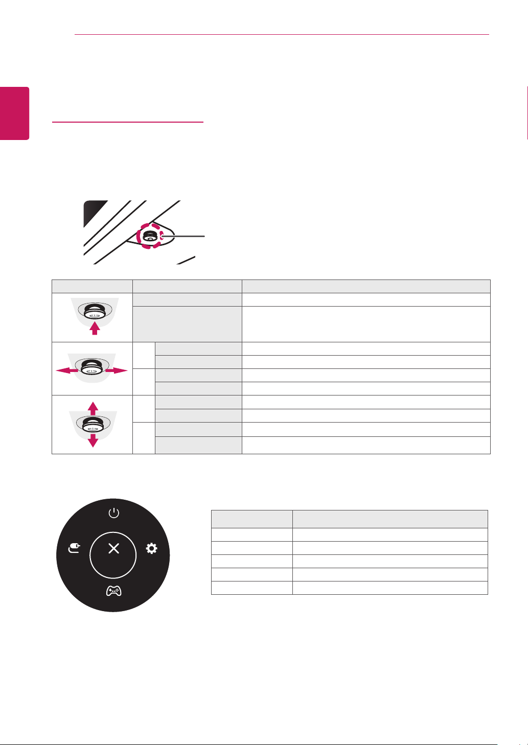
Activating the Main Menu
Press the joystick button on the bottom of the monitor.
1
Move the joystick up/down (▲/▼) and left/right (◄/►) to set the options.
2
Press the joystick button once more to exit the main menu.
3
Joystick Button
Button Menu Status Description
Main menu disabled Enables the main menu.
Main menu enabled
Main menu disabled Adjusts the monitor volume level.
◄
Main menu enabled Enters the Input features.
Main menu disabled Adjusts the monitor volume level.
►
Main menu enabled Enters the Settings feature.
Main menu disabled Displays the information on the current input.
▲
Main menu enabled Turns off the monitor.
Main menu disabled Displays the information on the current input.
▼
Main menu enabled Enters the Game Mode feature.
Exits the main menu.
(Holding down the button to turn off the monitor. You can turn off the
monitor this way at any time, including when the OSD is on.)
Main Menu Features
Power Off
SettingsInput Exit
Game Mode
Main Menu Description
Input Sets input mode.
Power Off Turns off the monitor.
Settings Configures the screen settings.
Game Mode Sets the game mode for gaming.
Exit Exits the main menu.
Page 21
User Settings
User Settings
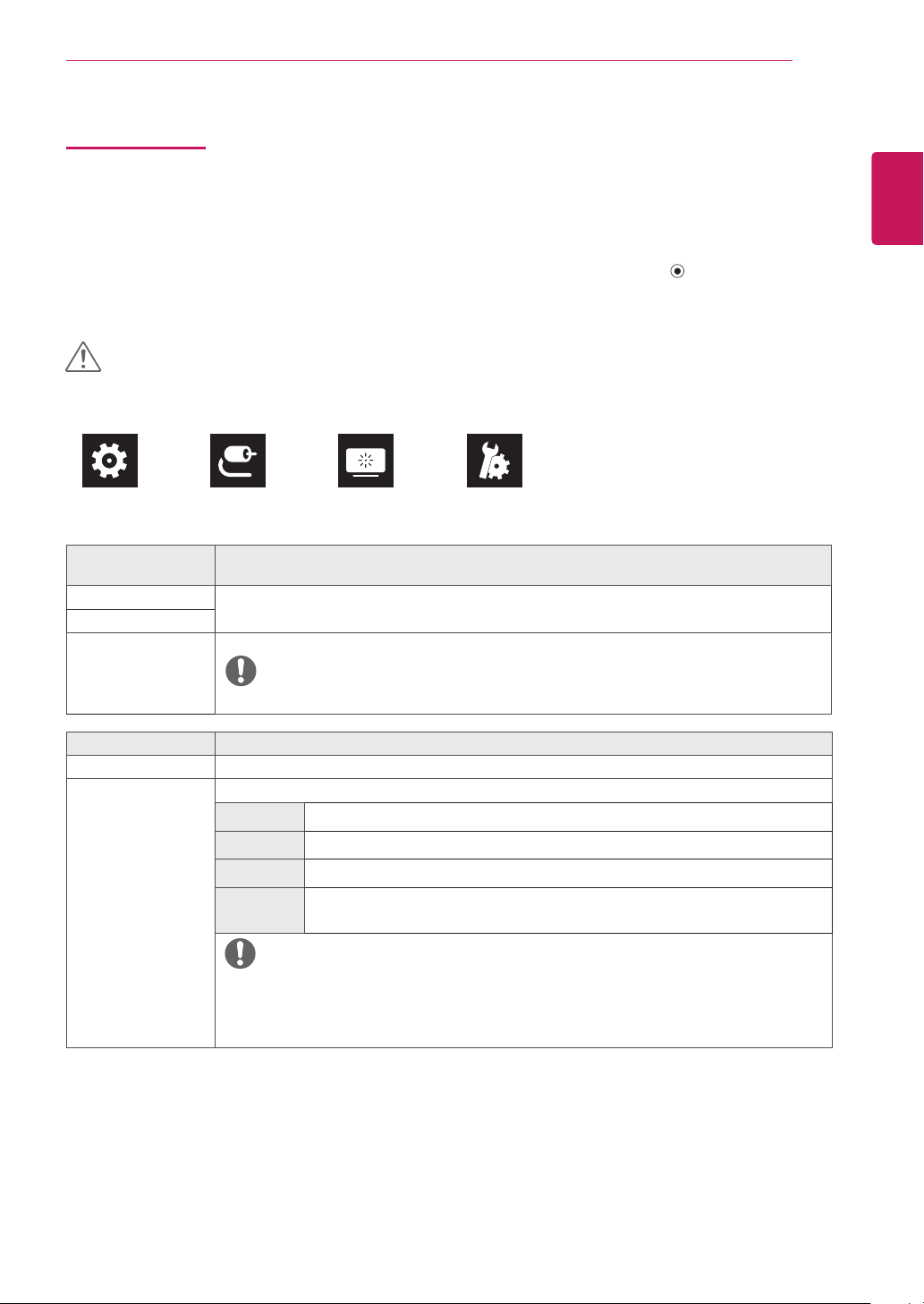
Menu Settings
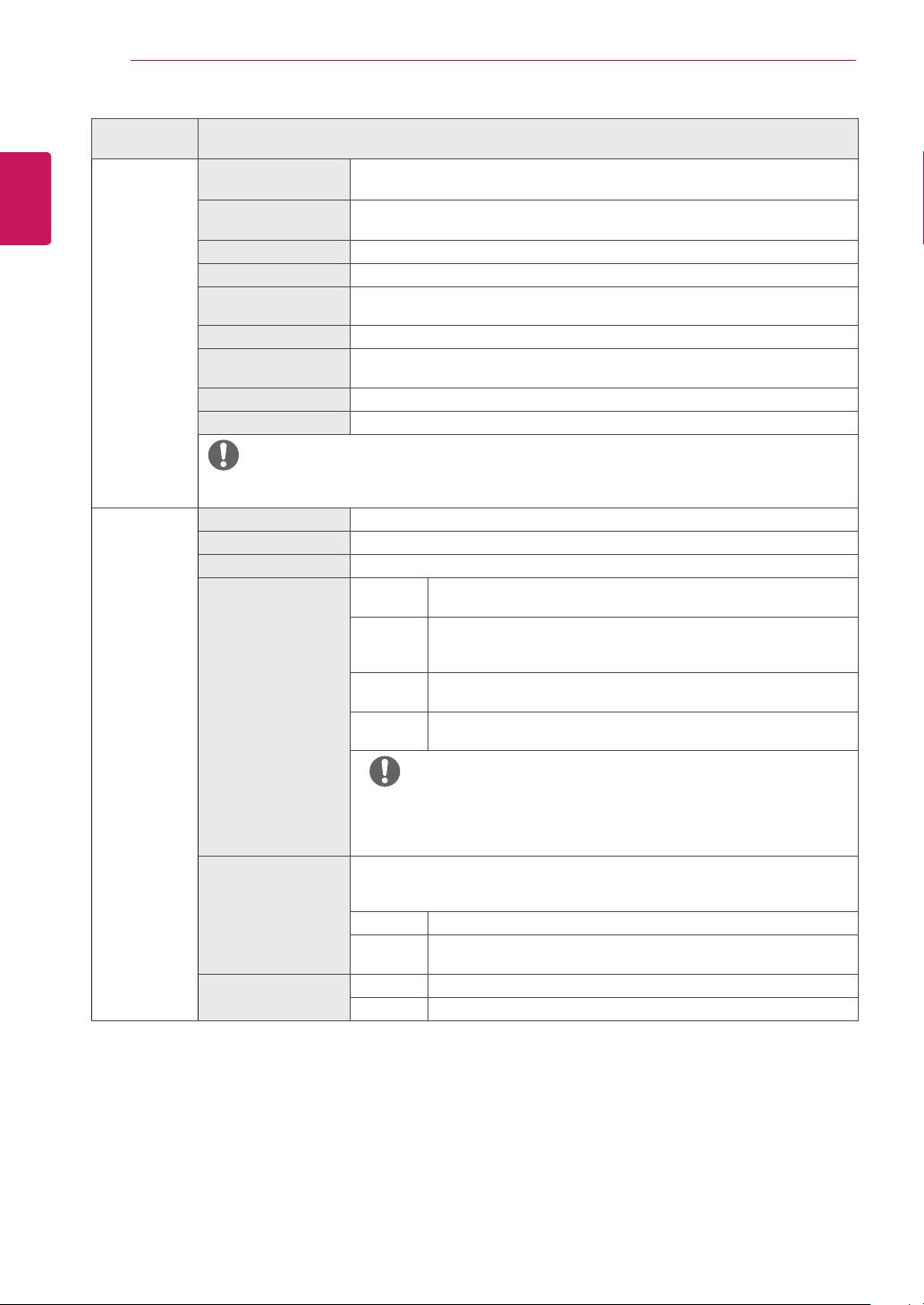
To view the OSD menu, press the joystick button at the bottom of the monitor and then enter the Settings.
1
Configure the options by moving the joystick up/down/left/right.
2
To return to the upper menu or set other menu items, move the joystick to◄ or pressing ( / Ok) it.
3
If you want to exit the OSD menu, move the joystick to ◄ until you exit.
4
When you enter the menu, instructions on how to use the button will appear in the bottom right corner of the screen.
y
CAUTION
Your monitor’s OSD (On Screen Display) may differ slightly from that shown in this manual.
y
Quick Settings Input Picture General
Each option is described below.
Settings > Quick Settings
Brightness
Contrast
Volume Adjusts the volume level.
Adjusts the color contrast and brightness of the screen.
Description
21
ENGLISH
ENG
NOTE
You can adjust Mute / Unmute by moving the joystick button to▼in the Volume menu.
y
Settings > Input Description
Input List Selects the input mode.
Aspect Ratio Adjusts the aspect ratio of the screen.
Full Wide Displays the video in wide-screen, regardless of the video signal input.
Original Displays video according to the aspect ratio of the video signal input.
Cinema1 Enlarges the screen with an aspect ratio of 21:9. (at 1080p)
Cinema2 Enlarges the screen with an aspect ratio of 21:9, including the black box at the bottom for
subtitles. (at 1080p)
NOTE
The display may look the same for Full Wide , Original at the recommended resolution (2560×1080).
y
There is no Cinema1, Cinema2 menu on FreeSync Mode. ( Go to Picture
y
Sync, to set FreeSync On or Off)
Game Adjust → Free-
→
Page 22
22
User Settings
ENGLISH
ENG
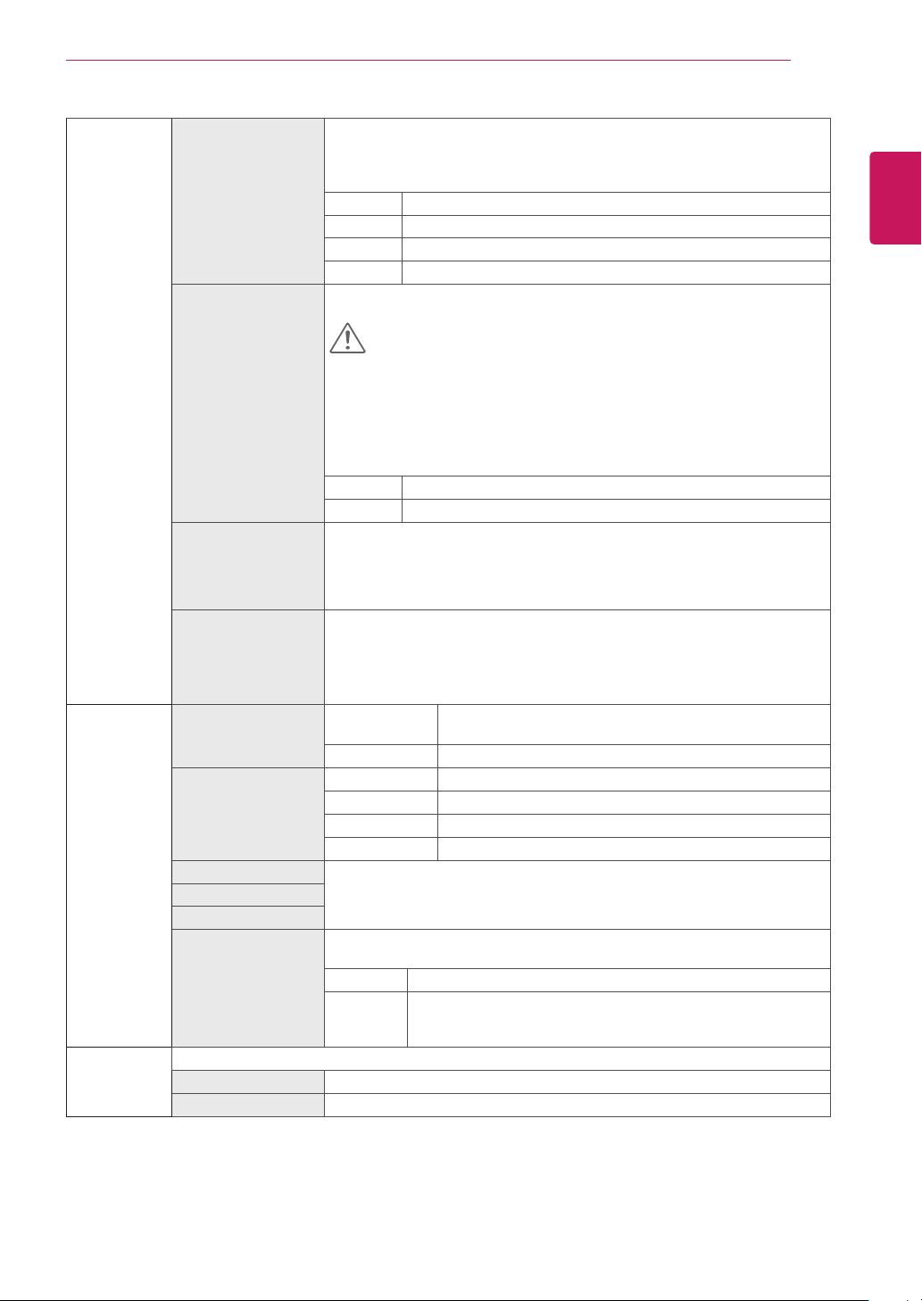
Settings >
Picture
Picture Mode Custom Allows the user to adjust each element. The color mode of the main menu can be
Reader Optimizes the screen for viewing documents. You can brighten the screen in the OSD
Photo Optimizes the screen for photos.
Cinema Optimizes the screen for video.
Color Weakness
FPS Game 1 This mode is optimized for FPS games.
FPS Game 2 It has a higher Black Stabilizer value than FPS Game 1. It is suitable for very dark FPS
RTS Game This mode is optimized for RTS Game.
Custom (Game) In this mode, users can customize various elements including game-related options.
adjusted.
menu.
This mode is for users who cannot distinguish between red and green. It enables users
with color weakness to easily distinguish between the two colors.
games.
Description
NOTE
If the picture mode is changed the screen may flicker or the resolution of your PC screen may be affected.
y
Picture Adjust Brightness Adjusts the brightness of the screen.
Contrast Adjusts the contrast of the screen.
Sharpness Adjusts the sharpness of the screen.
SUPER RESOLUTION+ High Optimized picture quality is displayed when a user wants crystal clear
Middle The optimized picture quality is displayed when a user wants images
Low The optimized picture quality is displayed when a user wants smooth and
Off Select this option for everyday viewing. SUPER RESOLUTION+ is turned
images. It is effective for high quality video or game.
between low and high modes for comfortable viewing. It is effective for
UCC or SD video.
natural images. It is effective for slow-moving pictures or still images.
off in this mode.
NOTE
Because this is a function to increase the sharpness of low resolution pictures, it is
y
not recommended to use the function for normal text or for desktop icons. Doing
so may result in unnecessarily high sharpness.
Black Level Sets the offset level (for HDMI only).
DFC On Adjusts the brightness automatically according to the screen.
yOffset: as a reference for a video signal, this is the darkest color the monitor can
display.
High Keeps the current contrast ratio of the screen.
Low Lowers the black levels and raises the white levels from the current
contrast ratio of the screen.
Off Disables the DFC feature.
Page 23
User Settings
23
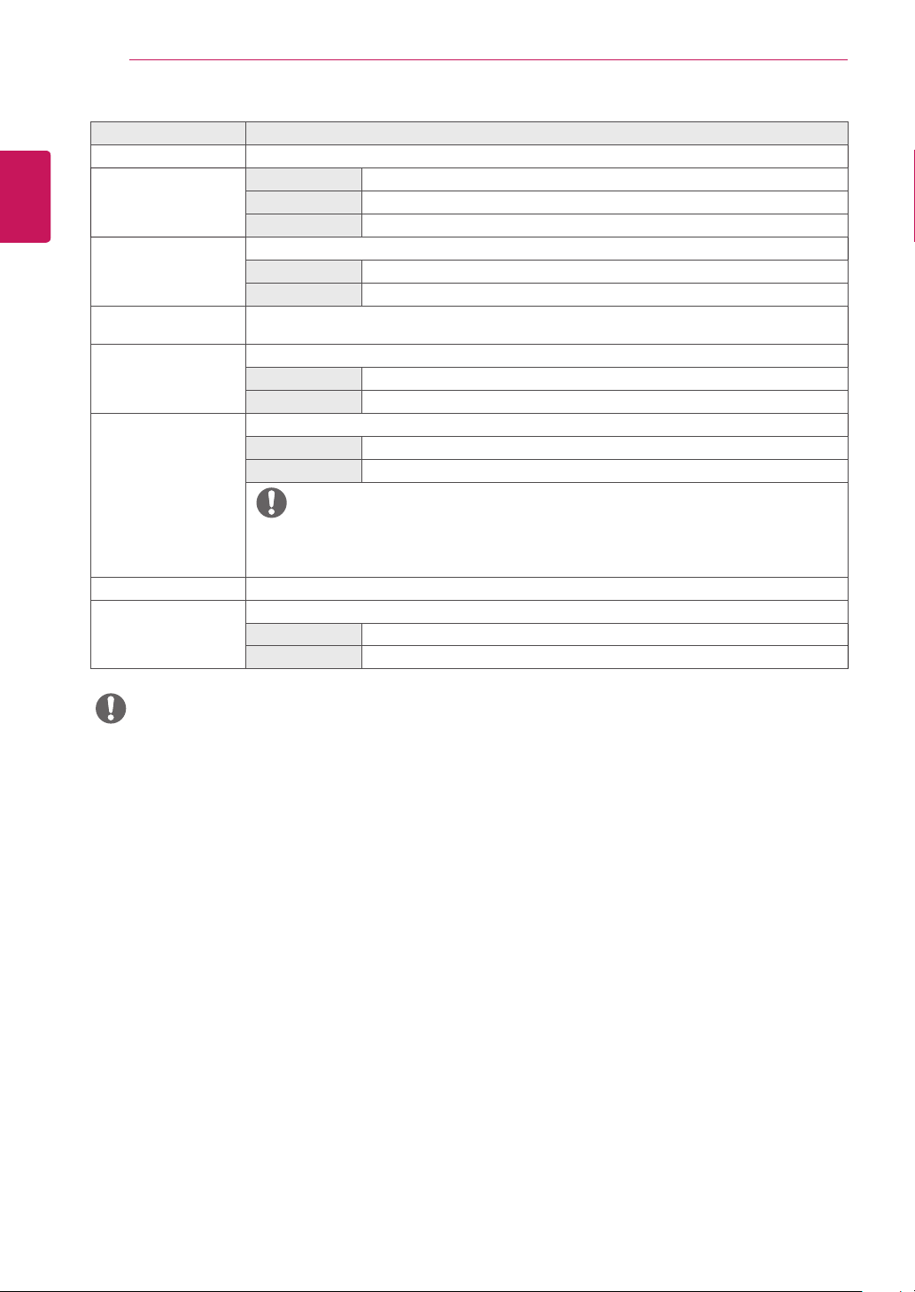
Game Adjust Response Time Sets a response time for displayed pictures based on the speed of the screen.
FreeSync Provides seamless and natural images by synchronizing the vertical frequency of the
For a normal environment, it is recommended that you use Fast.
For a fast-moving picture, it is recommended that you use Faster.
Setting to Faster may cause image sticking.
Faster Sets the response time to faster.
Fast Sets the response time to fast.
Normal Sets the response time to normal.
Off Does not use the response time improvement feature.
input signal with that of the output signal.
CAUTION
Supported Interface: HDMI.
y
Supported Graphic Card : A graphic card that supports AMD’s FreeSync is
y
necessary.
Supported Version : Make sure to update the graphic card to the latest driver.
y
For more information and requirement, refer to AMD website at http://www.
y
amd.com/FreeSync
On FreeSync function on.
Off FreeSync function off.
Black Stabilizer You can control the black contrast to have better visibility in dark scenes.
Cross Hair Cross Hair provides a mark on the center of the screen for First Person Shooter (FPS)
Color Adjust Gamma Mode 1, Mode 2,
Color Temp Custom The user can adjust it to red, green, or blue by customization.
Red You can customize the picture color using Red, Green, and Blue colors.
Green
Blue
Six Color Meets the user requirements for colors by adjusting the hue and saturation of the six
Picture Reset Do you want to Picture reset your settings?
Yes Reset
No Cancel
Increasing the Black Stabilizer value brightens the low gray level area on the screen.
(You can easily distinguish objects on dark game screens.)
Reducing the Black Stabilizer value darkens the low gray level area and increases the
dynamic contrast on the screen.
games. Users can select the cross hair that fits their gaming environment among four
different cross hairs.
When the monitor is off or enters energy saving mode, the Cross Hair
y
feature is automatically turned Off.
The higher the gamma value, the darker the image becomes. Likewise,
Mode 3
Mode 4 If you do not need to adjust the gamma settings, select Mode 4.
Warm Sets the screen color to a reddish tone.
Medium Sets the screen color between a red and blue tone.
Cool Sets the screen color to a bluish tone.
colors (Red, Green, Blue, Cyan, Magenta, Yellow) and then saving the settings.
Hue Adjusts the tone of the screen colors.
Saturation Adjusts the saturation of the screen colors. The lower the value, the
the lower the gamma value, the lighter the image becomes.
less saturated and brighter the colors become. The higher the value, the
more saturated and darker the colors become.
ENGLISH
ENG
Page 24
ENGLISH
ENG
User Settings
24
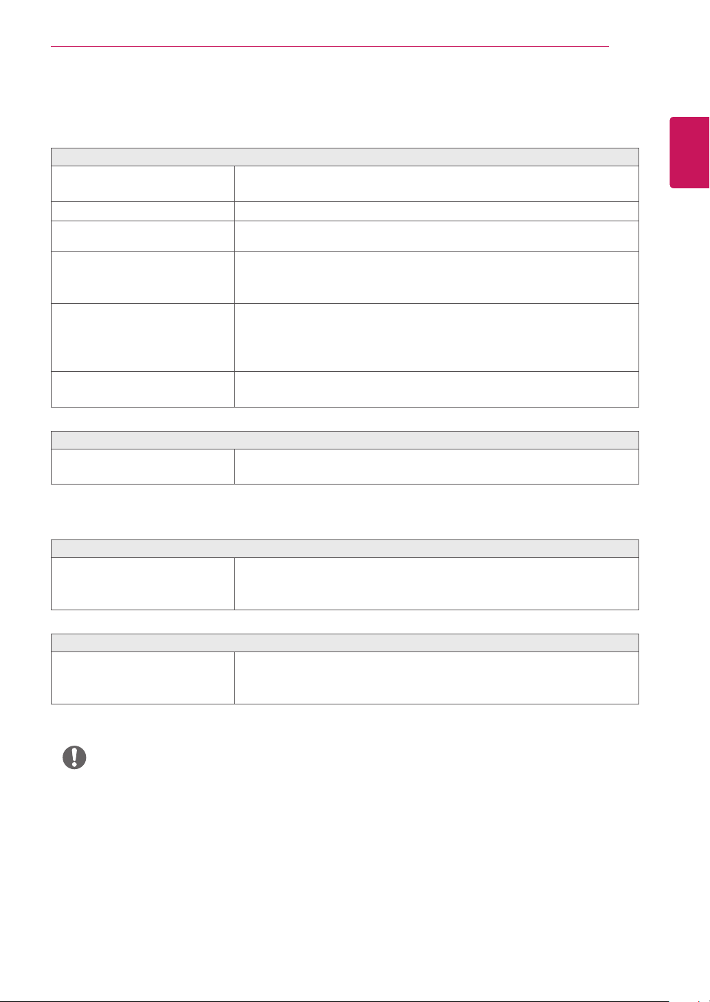
Settings > General Description
Language Sets the menu screen to the desired language.
SMART ENERGY
SAVING
Power LED Turns the power LED on the front of the monitor on.
Automatic Standby Feature that automatically turns off the monitor when there is no movement on the screen for a period
Buzzer This feature lets you set the sound generated from Buzzer when your monitor powers on to On.
OSD Lock This feature disables the configuration and adjustment of menus.
High Saves energy using the high-efficiency SMART ENERGY SAVING feature.
Low Saves energy using the low-efficiency SMART ENERGY SAVING feature.
Off Disables the SMART ENERGY SAVING feature.
On The power LED turns on.
Off The power LED turns off.
of time. You can set a timer for the auto-off function. (Off, 4 H, 6 H, and 8 H)
On Enables your monitor's Buzzer.
Off Disables your monitor's Buzzer.
On Enables OSD Lock.
Off Disables OSD Lock.
NOTE
All features are disabled except Brightness, Contrast, Volume, Input, OSD Lock, Information.
y
Information The display information will be shown the Model, Total Power On Time, Serial Number, Resolution.
Reset Do you want to reset your settings?
Yes Returns to the default settings.
No Cancel the select.
NOTE
Saving Data depends on the Panel. These values vary by panel and vendor. If the option SMART ENERGY SAVING is set High
y
or Low, then monitor luminance becomes higher or lower depending upon the source.
Page 25
TROUBLESHOOTING
25
TROUBLESHOOTING
Nothing is displayed on the screen.
Is the monitor's power cord plugged in?
Is the power LED on?
Is the power on and the power LED
displaying white?
Is the power LED blinking?
Is the OUT OF RANGE message being
displayed?
Is the No Signal message being
displayed?
The OSD lock message is being displayed.
Are some functions not available when
you press the Menu button?
Check if the power cord is correctly plugged into the power outlet.
y
Test the Power Plug using a lamp or other device.
y
Check the power cable connection and press the power button.
y
Check that the connected input is enabled (Settings > Input).
y
If the monitor is in sleep mode, move the mouse, or press any key on the
y
keyboard, to switch the display on.
Check if the computer is turned on.
y
This occurs when signals transferred from the PC (graphics card) are out
y
of the horizontal or vertical frequency range of the monitor. Please see
the Product Specification section of this manual to set the appropriate
frequency.
This is displayed when the signal cable between the PC and the monitor is
y
missing or disconnected. Check the cable and reconnect it.
The OSD is locked. Go to Settings > General and set OSD Lock to Off.
y
ENGLISH
ENG
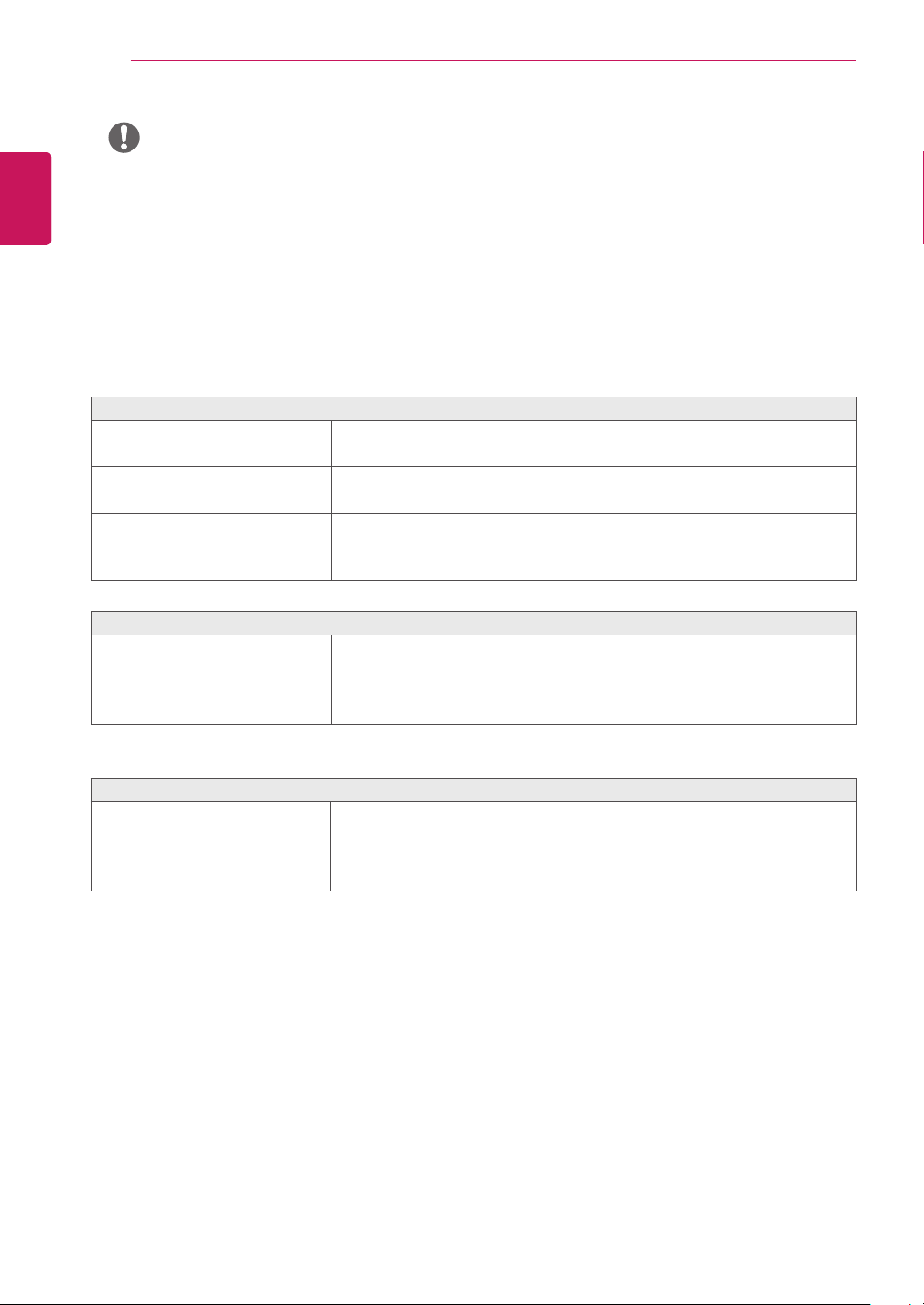
The screen retains an image.
Does image sticking occur even when
the monitor is turned off?
Screen display is unstable and shaky / Images displayed on the monitor leave shadow trails.
Did you select the appropriate
resolution?
Displaying a still image for a prolonged time may cause damage to the
y
screen, resulting in the retention of the image.
To extend the lifetime of the monitor, use a screensaver.
y
If the selected resolution is HDMI 1080i 60/50 Hz (interlaced), the screen
y
may be flickering. Change the resolution to 1080P or the recommended
resolution.
NOTE
Vertical frequency In order to display an image, the screen must be refreshed dozens of times per second, like a fluorescent
y
lamp. The number of times the screen is refreshed per second is called vertical frequency, or refresh rate, and is represented by
Hz.
Horizontal frequency The time it takes to display one horizontal line is called the horizontal cycle. If 1 is divided by the
y
horizontal interval, the result is the number of horizontal lines displayed per second. This is called horizontal frequency and is
represented by kHz.
Page 26
ENGLISH
ENG
TROUBLESHOOTING
26
NOTE
Check if the graphics card's resolution or frequency is within the range allowed by the monitor and set it to the
y
recommended (optimal) resolution in Control Panel > Display > settings.
Not setting the graphics card to the recommended (optimal) resolution may result in blurred text, a dimmed
y
screen, a truncated display area, or misalignment of the display.
The setting methods may be different depending on the computer or operating system, and some resolutions
y
may not be available depending on the performance of the graphics card. If this is the case, contact the
manufacturer of the computer or graphics card for assistance.
Some graphics cards may not support 2560×1080 resolution. If the resolution cannot be displayed, contact the
y
manufacturer of your graphics card.
The display color is abnormal.
Does the display appear discolored (16
colors)?
Does the display color appear unstable
or monochrome?
Are there spots on the screen?
Set the color to 24 bit (true color) or higher. In Windows, go to Control
y
Panel > Display > Settings > Color Quality.
Check if the signal cable is connected properly. Reconnect the cable or
y
reinsert the PC's graphics card.
When using the monitor, pixilated spots (red, green, blue, white, or black)
y
may appear on the screen. This is normal for an LCD screen. It is not an
error, nor is it related to the monitor's performance.
Do you see an "Unrecognized monitor, Plug&Play (VESA DDC) monitor found" message?
Have you installed the display driver?
Be sure to install the display driver from the display driver CD (or diskette)
y
that comes with your display. Or, you can also download the driver from
our web site: http://www.lg.com.
Make sure to check if the video card supports Plug&Play function.
y
No sound from the headphone port or speaker.
Are images displayed using DisplayPort
or HDMI input without sound?
Try increasing the volume using the button on the monitor.
y
Set the audio output of the PC to the monitor you are using. On Microsoft
y
Windows, go to Control Panel > Hardware and Sound > Sound > set the
monitor as default device.
Page 27
SPECIFICATIONS
27
SPECIFICATIONS
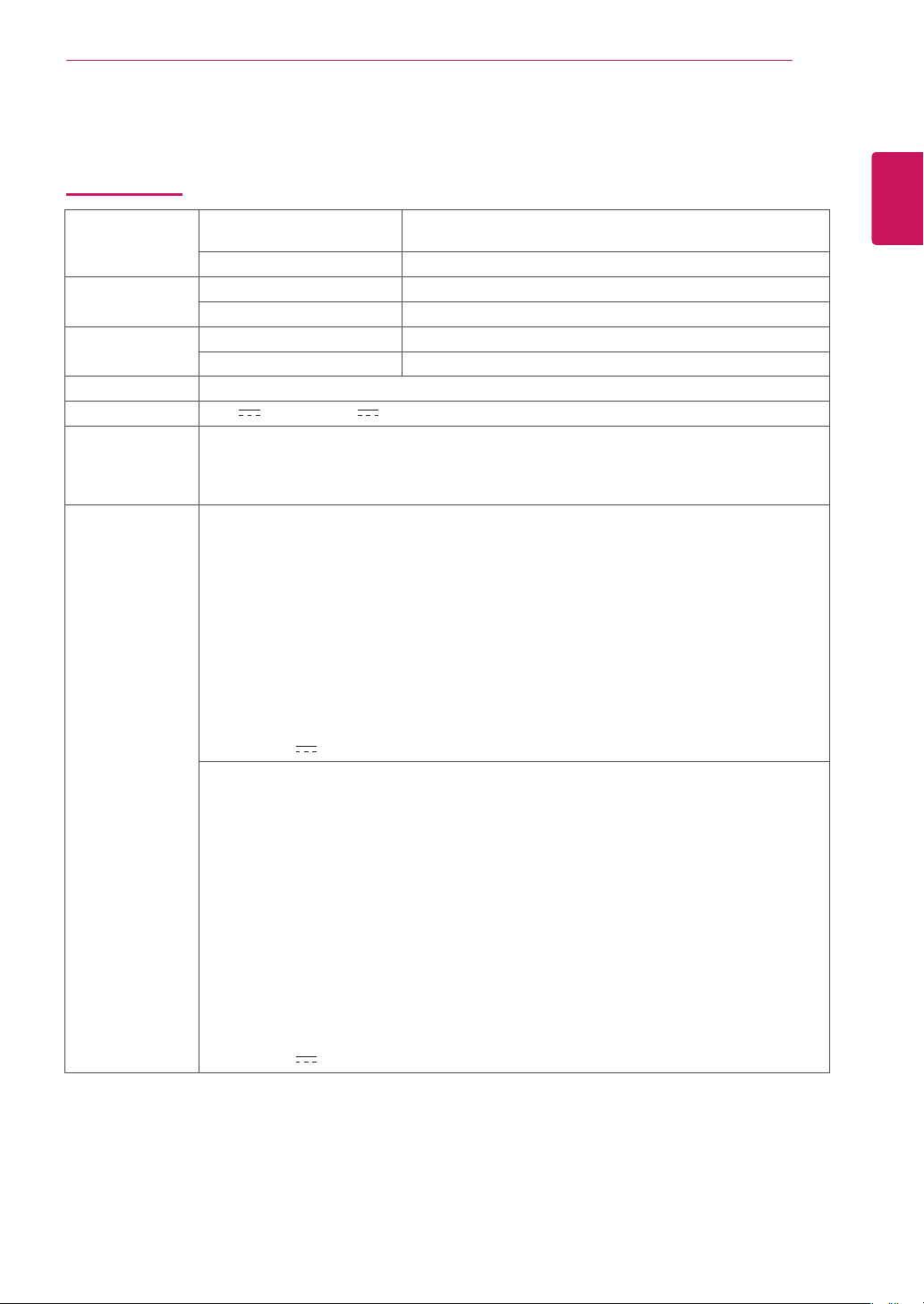
29WK500
LCD Screen Type TFT (Thin Film Transistor)
LCD (Liquid Crystal Display) Screen
Pixel Pitch 0.2628 mm x 0.2628 mm
Resolution Maximum Resolution 2560×1080 @ 75 Hz
Recommended Resolution 2560×1080 @ 60 Hz
Video Signal
Input Connector HDMI IN1, HDMI IN2, H/P
Power input 19 V 1.6 A Or 19 V 1.3 A
Power
consumption (Typ.)
AC/DC adaptor Type ADS-40SG-19-3 19032G, SHENZHEN HONOR ELECTRONIC production
Horizontal Frequency 30 kHz to 90 kHz
Vertical Frequency 56 Hz to 75 Hz
On mode: 20 W Typ. (ENERGY STAR® standard)*
25 W Typ. (Outgoing condition)**
Sleep Mode ≤ 0.5 W
Off Mode ≤ 0.3 W
Or type ADS-40FSG-19 19032GPG-1, SHENZHEN HONOR ELECTRONIC production
Or type ADS-40FSG-19 19032GPBR-1, SHENZHEN HONOR ELECTRONIC production
Or type ADS-40FSG-19 19032GPI-1, SHENZHEN HONOR ELECTRONIC production
Or type ADS-40FSG-19 19032GPCU-1, SHENZHEN HONOR ELECTRONIC production
Or type ADS-32FSG-19 19032EPCU-1L, SHENZHEN HONOR ELECTRONIC production
Or type LCAP21A, LIEN CHANG ELECTRONIC ENTERPRISE production
Or type LCAP26A-A, LIEN CHANG ELECTRONIC ENTERPRISE production
Or type LCAP26A-E, LIEN CHANG ELECTRONIC ENTERPRISE production
Or type LCAP26A-I, LIEN CHANG ELECTRONIC ENTERPRISE production
Or type LCAP26A-B, LIEN CHANG ELECTRONIC ENTERPRISE production
Or type LCAP51A, LIEN CHANG ELECTRONIC ENTERPRISE production
Or type PA-1031-23, Lite-On Technology Corporation production
Output: 19 V 1.7 A
Type ADS-40SG-19-3 19025G, SHENZHEN HONOR ELECTRONIC production
Or type ADS-40FSG-19 19025GPG-1, SHENZHEN HONOR ELECTRONIC production
Or type ADS-40FSG-19 19025GPBR-1, SHENZHEN HONOR ELECTRONIC production
Or type ADS-40FSG-19 19025GPI-1, SHENZHEN HONOR ELECTRONIC production
Or type ADS-40FSG-19 19025GPCU-1, SHENZHEN HONOR ELECTRONIC production
Or type ADS-40FSG-19 19025GPB-2, SHENZHEN HONOR ELECTRONIC production
Or type ADS-25FSG-19 19025EPCU-1L, SHENZHEN HONOR ELECTRONIC production
Or type LCAP21, LIEN CHANG ELECTRONIC ENTERPRISE production
Or type LCAP26-A, LIEN CHANG ELECTRONIC ENTERPRISE production
Or type LCAP26-E, LIEN CHANG ELECTRONIC ENTERPRISE production
Or type LCAP26-I, LIEN CHANG ELECTRONIC ENTERPRISE production
Or type LCAP26-B, LIEN CHANG ELECTRONIC ENTERPRISE production
Or type LCAP51, LIEN CHANG ELECTRONIC ENTERPRISE production
Or type WA-24C19FS, Asian Power Devices Inc. production
Or type WA-24C19FN, Asian Power Devices Inc. production
Or type DA-24B19, Asian Power Devices Inc. production
Output: 19 V 1.3 A
ENGLISH
ENG
Page 28
SPECIFICATIONS
28
ENGLISH
ENG
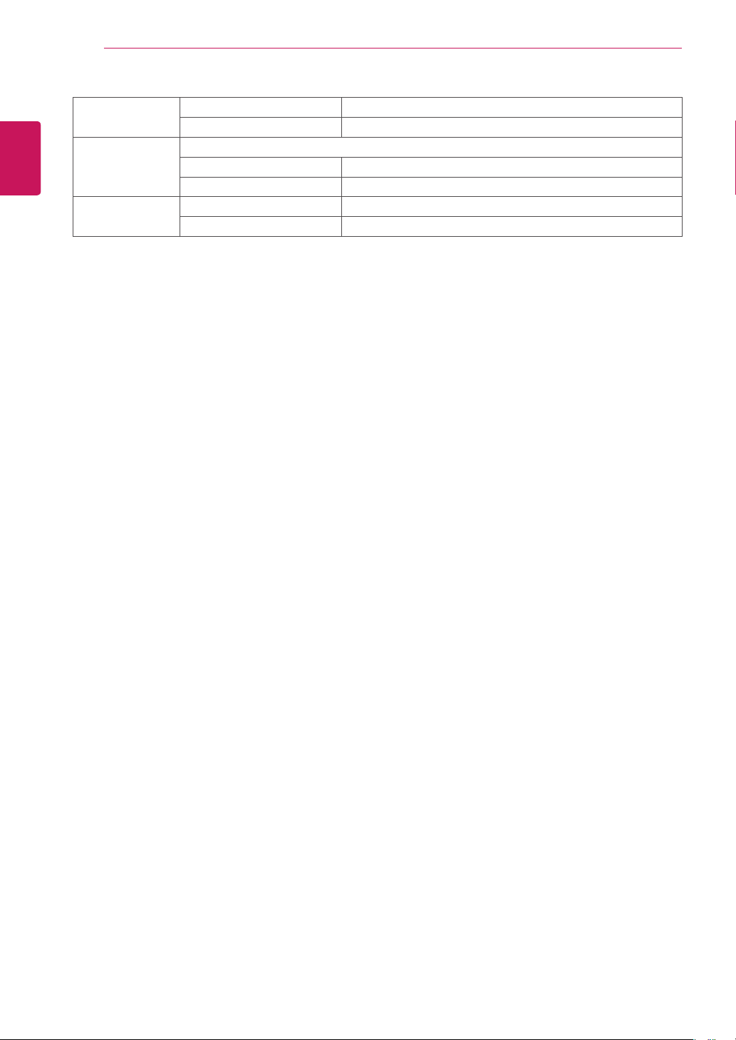
Environmental
Conditions
Dimension Monitor Size (Width x Height x Depth)
Weight (Without
Packaging)
The specifications are subject to change without notice.
* The power consumption level can be different by operating condition and monitor setting.
* The On mode power consumption is measured with ENERGY STAR® test standard.
** The On mode power consumption is measured with LGE test standard (Full White pattern , Maximum resolution).
Operating Condition Temperature: 0°C to 40°C; Humidity: < 80%
Storing Condition Temperature: -20°C to 60°C; Humidity: < 85%
With Stand 698.1 mm x 410.9 mm x 209.4 mm
Without Stand 698.1 mm x 317.5 mm x 76.9 mm
With Stand 4.9 kg
Without Stand 4.4 kg
Page 29
SPECIFICATIONS
29
SPECIFICATIONS
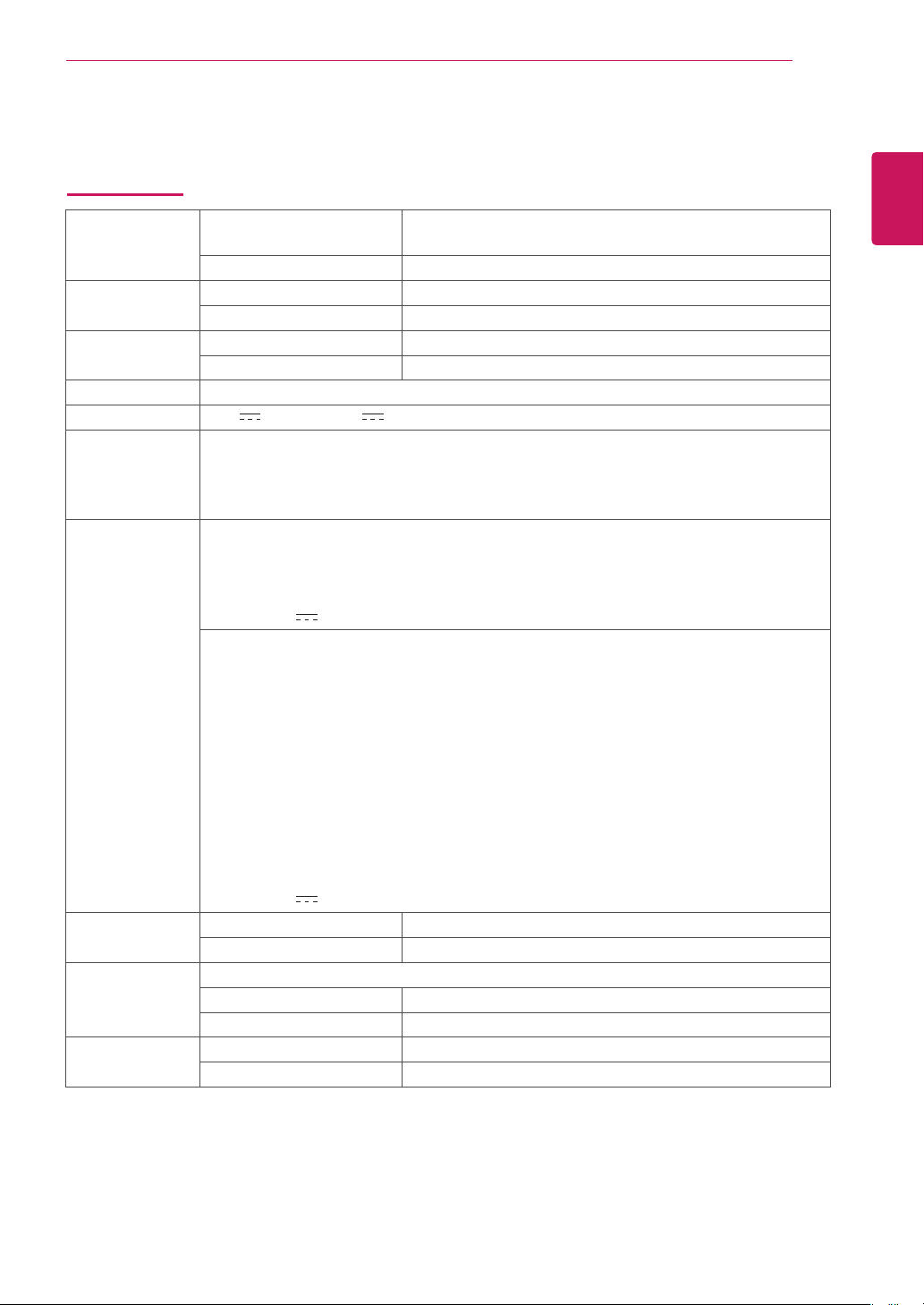
34WK500
LCD Screen Type TFT (Thin Film Transistor)
LCD (Liquid Crystal Display) Screen
Pixel Pitch 0.312 mm x 0.310 mm
Resolution Maximum Resolution 2560×1080 @ 75 Hz
Recommended Resolution 2560×1080 @ 60 Hz
Video Signal
Input Connector HDMI IN1, HDMI IN2, H/P
Power input 19 V 2.0 A Or 19 V 1.6 A
Power
consumption (Typ.)
AC/DC adaptor Type ADS-45SN-19-3 19040G, SHENZHEN HONOR ELECTRONIC production
Environmental
Conditions
Dimension Monitor Size (Width x Height x Depth)
Weight (Without
Packaging)
Horizontal Frequency 30 kHz to 90 kHz
Vertical Frequency 56 Hz to 75 Hz
On mode: 26 W Typ. (ENERGY STAR® standard)*
35 W Typ. (Outgoing condition)**
Sleep Mode ≤ 0.5 W
Off Mode ≤ 0.3 W
Or type LCAP21C, LIEN CHANG ELECTRONIC ENTERPRISE production
Or type LCAP26B-E, LIEN CHANG ELECTRONIC ENTERPRISE production
Or type LCAP26B-A, LIEN CHANG ELECTRONIC ENTERPRISE production
Output: 19 V 2.1 A
Type ADS-40SG-19-3 19032G, SHENZHEN HONOR ELECTRONIC production
Or type ADS-40FSG-19 19032GPG-1, SHENZHEN HONOR ELECTRONIC production
Or type ADS-40FSG-19 19032GPBR-1, SHENZHEN HONOR ELECTRONIC production
Or type ADS-40FSG-19 19032GPI-1, SHENZHEN HONOR ELECTRONIC production
Or type ADS-40FSG-19 19032GPCU-1, SHENZHEN HONOR ELECTRONIC production
Or type ADS-32FSG-19 19032EPCU-1L, SHENZHEN HONOR ELECTRONIC production
Or type LCAP21A, LIEN CHANG ELECTRONIC ENTERPRISE production
Or type LCAP26A-A, LIEN CHANG ELECTRONIC ENTERPRISE production
Or type LCAP26A-E, LIEN CHANG ELECTRONIC ENTERPRISE production
Or type LCAP26A-I, LIEN CHANG ELECTRONIC ENTERPRISE production
Or type LCAP26A-B, LIEN CHANG ELECTRONIC ENTERPRISE production
Or type LCAP51A, LIEN CHANG ELECTRONIC ENTERPRISE production
Output: 19 V 1.7 A
Operating Condition Temperature: 0°C to 40°C; Humidity: < 80%
Storing Condition Temperature: -20°C to 60°C; Humidity: < 85%
With Stand 828.5 mm x 460.7 mm x 209.4 mm
Without Stand 828.5 mm x 370.2 mm x 41.5 mm
With Stand 6.9 kg
Without Stand 6.1 kg
ENGLISH
ENG
The specifications are subject to change without notice.
* The power consumption level can be different by operating condition and monitor setting.
* The On mode power consumption is measured with ENERGY STAR® test standard.
** The On mode power consumption is measured with LGE test standard (Full White pattern,Maximum resolution).
Page 30
ENGLISH
ENG
SPECIFICATIONS
30
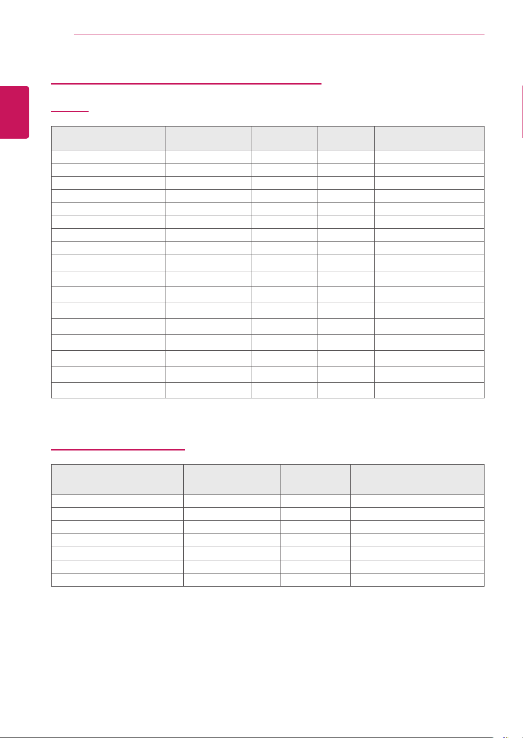
Factory Support Mode (Preset Mode, PC)
HDMI
Resolution
(HDMI)
720 x 400 31.468 70.08 -/+
640 x 480 31.469 59.94 -/-
640 x 480 37.5 75 -/-
800 x 600 37.879 60.317 +/+
800 x 600 46.875 75 +/+
1024 x 768 48.363 60 -/-
1024 x 768 60.123 75.029 +/+
1152 x 864 67.5 60 +/+
1280 x 720 45 60 +/+
1280 x 1024 63.981 60.02 +/+
1280 x 1024 79.976 75.025 +/+
1600 x 900 60 60 +/+
1680 x 1050 65.29 59.954 -/+
1920 x 1080 67.5 60 +/-
1920 x 1080 83.89 74.97 +/-
2560 x 1080 66.7 60 -/+
2560 x 1080 83.92 74.99 +/-
Horizontal
Frequency(kHz)
Vertical
Frequency(Hz)
Polarity(H/V) Remarks
HDMI Timing (Video)
Factory support mode
(Preset Mode)
480p 31.5 60
576P 31.25 50
720p 37.5 50
720p 45.0 60
1080p 56.25 50
1080p 66.7 60
1080p 83.92 75
Horizontal
Frequency(kHz)
Vertical
Frequency(Hz)
Remarks
Page 31
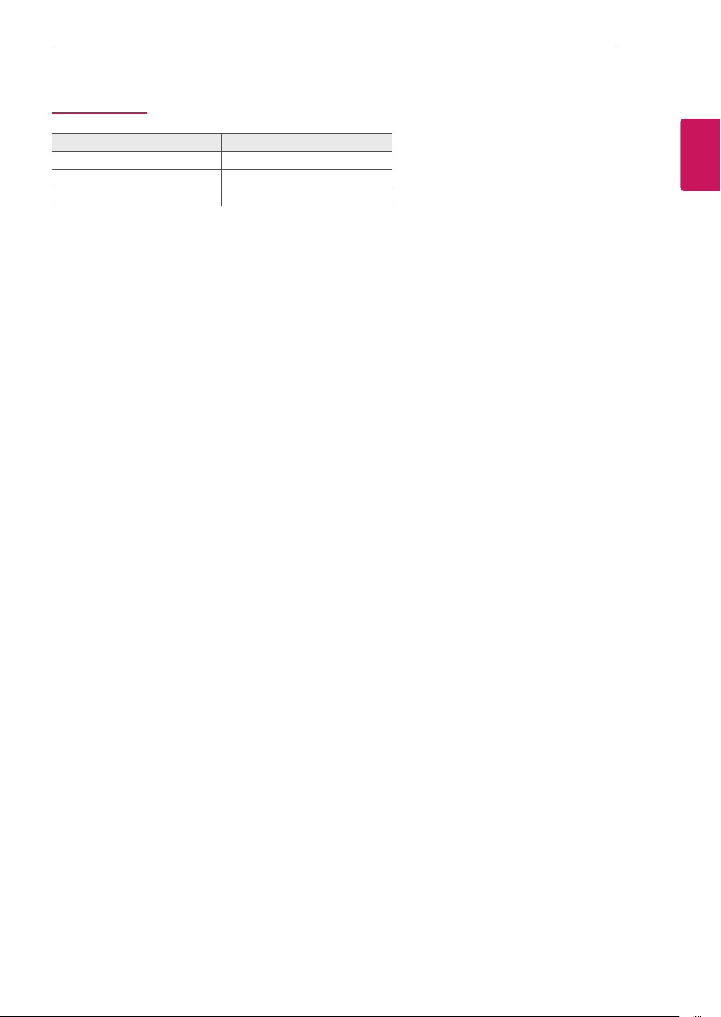
Power LED
Mode LED Color
On Mode White (For a few seconds)
Sleep Mode Off
Off Mode Off
SPECIFICATIONS
31
ENGLISH
ENG
Page 32
This device meets the EMC requirements for home
appliances (Class B) and is intended for home usage.
This device can be used in all regions. Read the
owner's manual (CD) carefully and keep it at hand.
Please note that the label attached to the product
provides information for technical support.
MODEL
SERIAL
ENERGY STAR is a set of power-saving
guidelines issued by the U.S.Environmental
Protection Agency(EPA).
As an ENERGY STAR Partner LGE U. S.
A.,Inc. has determined that this product
meets the ENERGY STAR guidelines for
energy efficiency.
Refer to ENERGY STAR.gov for more information
on the ENERGY STAR program.
 Loading...