

Page 1

Internal Use Only
North/Latin America http://aic.lgservice.com
Europe/Africa http://eic.lgservice.com
Asia/Oceania http://biz.lgservice.com
IPS LED MONITOR
SERVICE MANUAL
CHASSIS : LM94Q
MODEL : 34UM94/95
MODEL : 34UM94/95-PD/34UM95-PE
CAUTION
BEFORE SERVICING THE CHASSIS,
READ THE SAFETY PRECAUTIONS IN THIS MANUAL.
Printed in KoreaP/NO : MFL63731165 (1408-REV02)
Page 2

CONTENTS
CONTENTS .............................................................................................. 2
SAFETY PRECAUTIONS ........................................................................ 3
SPECIFICATION ....................................................................................... 4
ADJUSTMENT INSTRUCTION ................................................................ 5
BLOCK DIAGRAM .................................................................................... 9
EXPLODED VIEW .................................................................................. 10
SCHEMATIC CIRCUIT DIAGRAM ..............................................................
Only for training and service purposes
- 2 -
LGE Internal Use OnlyCopyright © LG Electronics. Inc. All rights reserved.
Page 3
To Instrument's
exposed
METALLIC PARTS
Good Earth Ground
such as WATER PIPE,
CONDUIT etc.
AC Volt-meter
SAFETY PRECAUTIONS
IMPORTANT SAFETY NOTICE
Many electrical and mechanical parts in this chassis have special safety-related characteristics. These parts are identified by in the
Schematic Diagram and Exploded View.
It is essential that these special safety parts should be replaced with the same components as recommended in this manual to prevent
Shock, Fire, or other Hazards.
Do not modify the original design without permission of manufacturer.
General Guidance
An isolation Transformer should always be used during the
servicing of a receiver whose chassis is not isolated from the AC
power line. Use a transformer of adequate power rating as this
protects the technician from accidents resulting in personal injury
from electrical shocks.
It will also protect the receiver and it's components from being
damaged by accidental shorts of th e circuitry that may be
inadvertently introduced during the service operation.
If any fuse (or Fusible Resistor) in this TV receiver is blown,
replace it with the specified.
When replacing a high wattage resistor (Oxide Metal Film Resistor,
over 1 W), keep the resistor 10 mm away from PCB.
Keep wires away from high voltage or high temperature parts.
Before returning the receiver to the customer,
always perform an AC leakage current check on the exposed
metallic parts of the cabinet, such as antennas, terminals, etc., to
be sure the set is safe to operate without damage of electrical
shock.
Leakage Current Cold Check(Antenna Cold Check)
With the instrument AC plug removed from AC source, connect an
electrical jumper across the two AC plug prongs. Place the AC
switch in the on position, connect one lead of ohm-meter to the AC
plug prongs tied together and touch other ohm-meter lead in turn to
each exposed metallic parts such as antenna terminals, phone
jacks, etc.
If the exposed metallic part has a return path to the chassis, the
measured resistance should be between 1 MΩ and 5.2 MΩ.
When the exposed metal has no return path to the chassis the
reading must be infinite.
An other abnormality exists that must be corrected before the
receiver is returned to the customer.
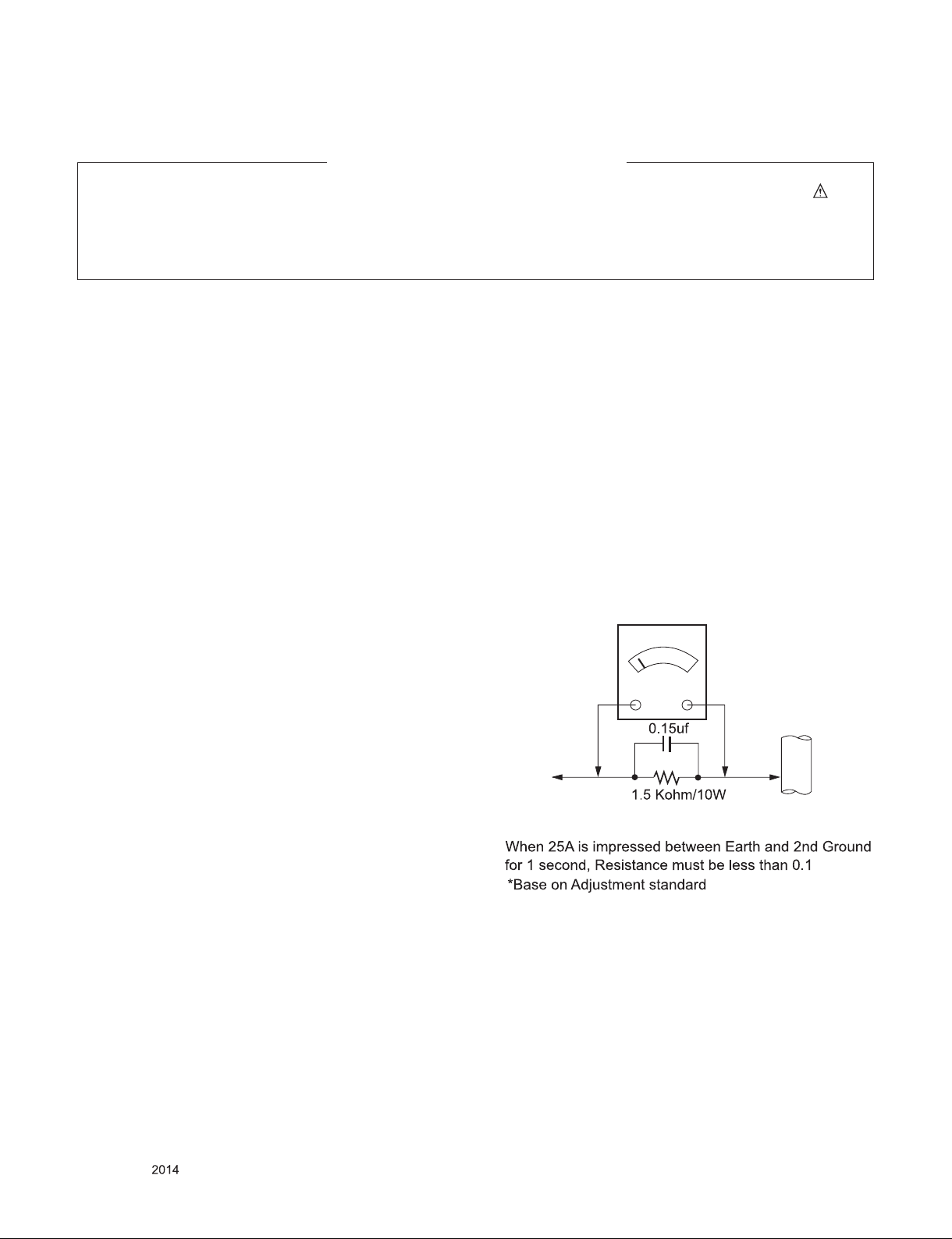
Leakage Current Hot Check (See below Figure)
Plug the AC cord directly into the AC outlet.
Do not use a line Isolation Transformer during this check.
Connect 1.5 K / 10 watt resistor in parallel with a 0.15 uF capacitor
between a known good earth ground (Water Pipe, Conduit, etc.)
and the exposed metallic parts.
Measure the AC voltage across the resistor using AC voltmeter
with 1000 ohms/volt or more sensitivity.
Reverse plug the AC cord into the AC outlet and repeat AC voltage
measurements for each exp ose d metallic par t. Any voltage
measured must not exceed 0.75 volt RMS which is corresponds to
0.5 mA.
In case any measurement is out of the limits specified, there is
possibility of shock hazard and the set must be checked and
repaired before it is returned to the customer.
Leakage Current Hot Check circuit
Only for training and service purposes
- 3 -
LGE Internal Use OnlyCopyright © LG Electronics. Inc. All rights reserved.
Page 4

SPECIFICATION
NOTE : Specifications and others are subject to change without notice for improvement
1. Module General Specification
No Item Content Remark
1 Customer BRAND
2 User Model Name 34UM95
3 Sale region Refer to Sufx standard
4 Feature 34” Wide LCD MONITOR(WQHD)
5 Chassis Name LM94Q
6 General Scope External SW &Adj. 5-way joystick switch
Function PBP, Picture Mode Ratio, Gamma Calibration, SES, Six
Color, 7W speaker x 2, Thunderbolt x 2, Displayport,
HDMI x 2, TCF, Screen split, USB hub(USB3.0 x 1,
USB2.0 x 2), 10-bit color depth(Displayport),
DC switch (34UM95-PE Only)
7 Power Code Length : 1.55±0.05 M
Shape : Wall-out
Color : Black
Weight : 0.16kg
8 Cable TBT(Thunderbolt) Length : ,Shape : ,Color: ,Pin Do not provide
USB Length : ,Shape : ,Color: ,Pin Do not provide
Audio Length : ,Shape : ,Color: ,Pin Do not provide
HDMI Length : 1.8m
Shape : Detachable Type
Color : black
Weight : 0.11kg
9 Power Input: AC100~240V 50~60Hz, 2A Max
Output: DC 19V 7.37A
140W Adapter
Weight : 0.58kg
10 Applying module list P/No Specication
EAJ62509601(ZBD)
EAJ62767601(Dot free)
.
Refer to Sufx standard and power cord
table
EAD00926103
EAY62949006
LM340UW1-SSA1
Only for training and service purposes
- 4 -
LGE Internal Use OnlyCopyright © LG Electronics. Inc. All rights reserved.
Page 5

ADJUSTMENT INSTRUCTION
1. Application Range
This document is applied to LM94Q chassis 34” LCD Monitor
which is manufactured in Monitor Factory or is produced on
the basis of this data.
2. Designation
(1) Th e ad justm ent is accord ing to the order whic h is
designated and which must be followed, according to the
plan which can be changed only on agreeing.
(2) Power Adjustment: Free Voltage
(3) Magnetic Field Condition: Nil.
(4) Input signal Unit: Product Specification Standard
(5) Reserve after operation: Above 5 Minutes (Heat Run)
Temperature : at 25 °C ± 5 °C
Relative humidity : 65 % ± 10 %
Input voltage : 100 V~ 240 V, 50/60Hz
(6) Adju stment equipments: Color Ana lyzer (CA-210 or
CA-110), DDC Adjustment Jig equipment,
3. Main PCB check process
* APC - After Manual-Insult, executing APC
3.1. ADC Process
(1) 34UM95 doesn’t need ADC process because it has only
digital input like DisplayPort and HDMI.
3.2. EDID Process
3.2.1. EDID Download
F/W includes default EDID for All input ports, aging on Mode If
AC ON, default EDID is automatically loaded to EEPROM.
Update serial number in EDID of HDMI1.
3.2.2. Data ( 128 Bytes )
- EDID Ver. 1.3 FOR HDMI 1 (256Byte)
- EDID Ver. 1.3 FOR HDMI 2 (256Byte)
- EDID Ver. 1.4 FOR Display Port (256Byte)
* Caution : Never connect HDMI Cable when execute NVRAM
Init and AC On at first for downloading HDMI EDID
automatically.
No Item Content 16 Data
1 Manufacturer ID GSM 1E 6D
2 Product ID HDMI 1 : 30423
HDMI 2 : 30423
Display Port : 30424
Thunderbolt : 30427
3 Year 2013 17
4 Version 1 1
5 Revision HDMI : 3
DP : 4
6 Serial Number * *
7 Week ** **
8 Model Name 34UM95 --
9 Check Sum **** ****
10 Special Item Need to Input Serial Number
** Protocol : DDC 2AB
Only for training and service purposes
D7 76
D7 76
D8 76
DB 76
HDMI : 3
DP : 4
- 5 -
LGE Internal Use OnlyCopyright © LG Electronics. Inc. All rights reserved.
Page 6

- EDID Ver. 1.4 FOR Thunderbolt (256Byte)
3.3. Function Check
3.3.1. Check Screen
■ Check input and signal items. (cf. work instructions)
1. HDMI1/2 (3440 x 1440 @30Hz)
2. DisplayPort1.2 (3440 x 1440 @60Hz) - using PC
3. Thunderbolt (3440 x 1440 @30Hz) - using PC
4. Total Assembly line process
4.1. Write HDCP Key
- Write HDCP Key into EEPROM by using DDC2AB protocol
& HDCP Adjustment Jig equipment.
- If error is occurred, try to write again.
Insert HDMI Jack which is connected with PC for White
Balance or equivalent device.
-> Total Assembl y line shoul d check whether the co lor
coordinate(x,y) data refer to below table were meet or not.
* Note : Manual W/B process
(1) Push the “OK” key for 3 sec.
(2) and push the “LEFT” or “RIGHT” Key.
(3) In Service Menu.
* When doing Adjustment, Please make circumstance as
below.
Color Temperature Luminance(cd/m2)
Cool Medium Warm Cool Medium Warm
9,300k 8,000k 6,500k Min :
170
°K °K °K
X=0.283
(±0.03)
Y=0.298
(±0.03)
*Note : x,y coordinates are drifted about 0.007 after 30 mins
* Note : Manual W/B process
X=0.295
(±0.03)
Y=0.305
(±0.03)
<Test Signal>
Inner pattern
(255gray,100IRE)
heat-run. So checking color coordinate within 5-min at
total assembly line, consider x,y coordinates might be
up to 0.007 than x,y target of each color temperature.
1) Power off => Power on
( ‘<-’ 3 times, ‘->’ 1 time and push ‘◎’)
2) and push the “<-” or “->”.
3) In Service Menu.
X=0.313
(±0.03)
Y=0.329
(±0.03)
Min :
200
<Test Signal>
Inner pattern
(255gray,100IRE)
Min :
260
4.2. White balance adjustment
- Adjust PRES ET Warm(6500K) Color coor dinates and
Gamma calibration .
■ Input Gamma calibration Pattern (R,G,B, Grey 20 )
■ Set as Warm(6500K) by commanding COLOR_MODE_
CHANGE Command code.
■ Gamma calibration and verify
Start - Read Elapsed time - Measure - Verify - Output
Report - End
■ Warm(6500K) Color adjustment.
Adjust to meet x/y color coordinate as below.
2~4 min 4~8min 8~10min 10~25min 25~40min 40min~
x 0.318 0.318 0.317 0.316 0.314 0.313
y 0.339 0.338 0.337 0.334 0.332 0.329
* Save Warm(6500K) Color by commanding COLOR SAVE
Command code.
Only for training and service purposes
* When doing Adjustment, Please make circumstance as
below.
4.3. DPM Operation check
■ Measurement Condition: 100 ~ 240 V @ 50/60Hz
(1) Set Input to DVI-D, DisplayPort, HDMI1, HDMI2
(2) Turn off the source device.
(3) Check DPM operation refer to the below table.
Operating
Condition
Sleep
mode
Off
mode
- 6 -
Sync (H/V)
or Video
Off/Off Off RED
- - Off 0.5(PD)
EUT
(MSPG6100)
LED
(SET)
blinking
Off 0.3(PE)
LGE Internal Use OnlyCopyright © LG Electronics. Inc. All rights reserved.
Wattage
(W)
1.2
Page 7

5. Signal composition for adjustment
5.1. I2C (100K BPS)
5.2. COMMUNICATION START
# Until ACK BIT goes LOW, Repeat it.
5.3. Command form.
Command form use DDC2AB standard communication
protocol.
a. LEN : DATA BYTE number to send.
b. CMD : Command language that monitor executes.
c. VAL : FOS DATA
d. CS : Dada’s CHECHSUM that transmit
e. DELAY : 50MS
f. A : Acknowledge
5.4. Screen adjust command (LENGTH = 84)
5.5. EEPROM Data Write
5.5.1 Siganl TABLE
LEN : 84h+Bytes
CMD : E8h
ADH : E2PROM Slave Address(A0,A2,A4,A6,A8,AA,AC,AE),
Not 00h(Reserved by Buffer To EEPROM)
ADL : E2PROM Sub Address(00~FF)
Data : Write data
Delay : 20ms
5.5.2. Command Set
No.
Adjustment
contents
1 EEP R O M
WRITE
2 (84+n) n-byte Write
* Use
■ FOS Default write :
<14mode data> write
SyncFlags,HPeriodH, HPeriodL, VtotalH,VtotalL,
SrcHTotalH, SrcHTotalL
SrcHStartH, SrcHStartL, SrcVStartH,SrcVStartL,
HsyncPhase
■ Temporary Data write: Write to particular address of
EEPROM.
CMD(hex) LEN Explanation
E8 94 16-Byte Write
Only for training and service purposes
- 7 -
LGE Internal Use OnlyCopyright © LG Electronics. Inc. All rights reserved.
Page 8

5.6. E2PROM Data Read
5.6.1. Signal TABLE
5.6.2. COMMAND SET
No. Adjustment
contents
1 EEPROM
READ
2 80 0-Page 80~FF Read
3 A2 0 1-Page 0~7F Read
4 80 1-Page 80~FF Read
5 A4 0 2-Page 0~7F Read
6 80 2-Page 80~FF Read
7 A6 0 3-Page 0~7F Read
8 80 3-Page 80~FF Read
9 A8 0 4-Page 0~7F Read
10 80 4-Page 80~FF Read
11 AA 0 5-Page 0~7F Read
12 80 5-Page 80~FF Read
13 AC 0 6-Page 0~7F Read
14 80 6-Page 80~FF Read
15 AE 0 7-Page 0~7F Read
16 80 7-Page 80~FF Read
CMD
ADH
ADL
(hex)
(hex)
E7 A0 0 0-Page 0~7F Read
Explanation
(hex)
5.6.3. Use
Read E2PROM’s specic area as unit of 128(80h)-byte. (84h)
5.6.4 EDID Write
EEPROM access by using DDC2B protocol
■ 1-Byte write
L : 0x00~0x7F
D : data
■ 8-byte write
L : 0x00,0x10,….0x70
5.6.5. EDID Read
- DDC2B Command.(A0/A1)
- 128 Byte transfer of EDID Buffer of MICOM
Only for training and service purposes
- 8 -
LGE Internal Use OnlyCopyright © LG Electronics. Inc. All rights reserved.
Page 9

BLOCK DIAGRAM
5YKVEJ
8 8
&&4
)$
&&4
/
(NCU J
/GOQT[
5&4#/
5&4#/
)$
8 8
&&4&CVCA=?
%5A5&1A
92 A 52 +A 5% -A
5&+A
R
.8&5
R
.8&5
#FFTGUUA=?
5NCXG
06
#FFTGUUA=?
(CNEQP
4KFIG
/*\
%.-(TGSWGPE[
)GPGTCVQT
%NQEM)GPGTCVQT
(5V41065OGGI8
2%+G
2QYGT
625
5YKVEJ
2QYGT
625
7RUVTGCO
6JW PF GTDQNV
#5/
75$5YKVEJ+%
#5/
75$*WD+%
#5/#
*WD%QPVTQN NGT
6JWPFGT
$1.6,CEM
6JW PF GT
$1.6,CEM
72
75$
5VTGCO
&QYP
75$
5VTGCO
&QYP
75$
5VTGCO
&QYP
75$
5VTGCO
&%.-/*\
2CPGNZ
9.'&A'0#$.'
9.'&A2&+/
9.'&A#&+/
&7A85
.'&&TKXGT+%
&7A&'
&7 A(#56A/76'
52+A%.-A+1
R
.8&5
R
.8&5
5'A92
5'A5%.
''241/
'#
&65
*+A+06'
5'A5&#
52+A%'A+1
/
''A%5A0
''A&1
''A%.-
''A&+
/
(NCUJ
/GOQT[
&2A6:.KPG
&CKU[%JCKP
52+A5+1
52+A5+1
52+A5+1
52+A5+1
&25KIPCN
75$A5%.
/CUVGT
06
*2A#176A4
*2A#176A.
)$
&&4&CVC=?
#FFTGUU=?
&&4
5&4#/
)$
#FFTGUU=?
%5 5&1 9 2A52+
5%-5&+
/
(NCU J
/GOQT[
*2. 4QWV
&&4&CVC=?
&&4
5&4#/
675$
75$VQ7#46 +%
75$A5&#
75$
''241/
#7&A#
#7& A.4%-
&09
&KIKVCN#/2
52.
524
(NCUJ
/GOQT[
%QPVTQN-G[
,Q[UVKEM-G[
&2
#&%-';-';
+%-';A5%.-';A5&#
#7& A5%-
#7& A/%.-
6/&5
*&/+
#0). '
*&/+
''241/
6/&5
*&/+
--
*&/+
''241/
Only for training and service purposes
- 9 -
LGE Internal Use OnlyCopyright © LG Electronics. Inc. All rights reserved.
Page 10
910
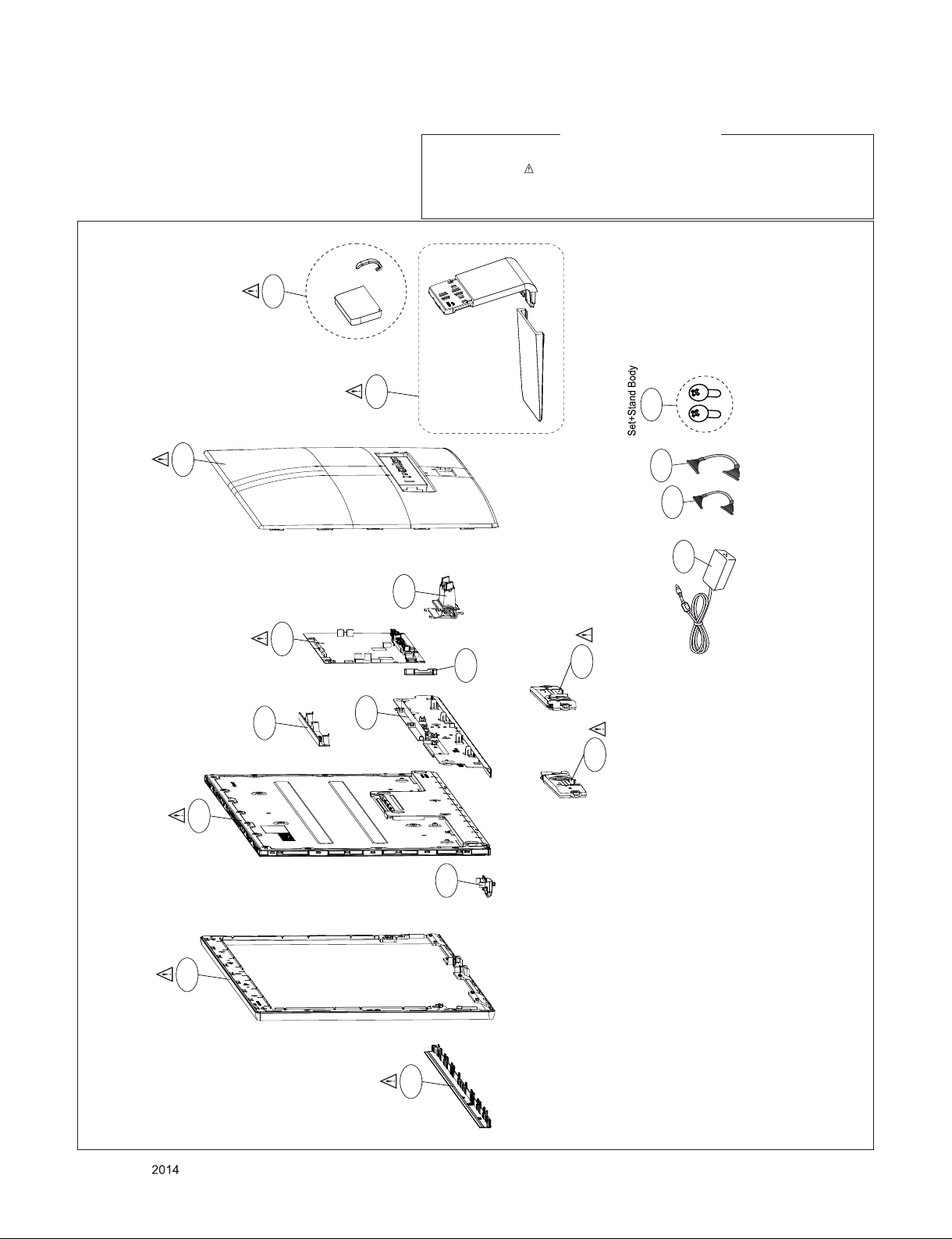
EXPLODED VIEW
IMPORTANT SAFETY NOTICE
Many electrical and mechanical parts in this chassis have special safety-related characteristics. These
parts are identified by in the Schematic Diagram and EXPLODED VIEW.
It is essential that these special safety parts should be replaced with the same components as
recommended in this manual to prevent X-RADIATION, Shock, Fire, or other Hazards.
Do not modify the original design without permission of manufacturer.
400
200
700
520
900
710
600
800
A10
LV2
LV1
A4
121
120
300
Only for training and service purposes
310
510
- 10 -
LGE Internal Use OnlyCopyright © LG Electronics. Inc. All rights reserved.
Page 11

JK100
Copyright © 2014 LG Electronics Inc. All rights reserved.
Only for training and service purposes
LGE Internal Use Only
62L020S-34A1N-7T0201-HF_
DP
1
2
3
4
5
6
7
8
9
10
11
12
13
14
15
16
17
18
19
20
21
JK1 01
51U 019S- 3441 N-6RL GM5-H F
HDMI
1
(ANGLE)
2
3
4
5
6
7
8
9
10
11
12
13
14
15
16
17
18
19
20
BODY_SHIELD
JK1 02
51V 019S- 35SN -CR2- B-LG
HDMI1
1
2
3
4
5
6
7
8
9
10
11
12
13
14
15
16
17
18
19
20
SHIELD
ML_LANE_3-
GND_3
ML_LANE_3+
ML_LANE_2-
GND_2
ML_LANE_2+
ML_LANE_1-
GND_1
ML_LANE_1+
ML_LANE_0-
GND_0
ML_LANE_0+
R104
CONFIG1
0
R105
CONFIG2
0
AUX_CH+
GND_4
AUX_CH-
HOT_PLUG
RETURN
DP_PWR[3.3V]
TMD S_DAT A2+
TMD S_DAT A2_S HIELD
TMD S_DAT A2-
TMD S_DAT A1+
TMD S_DAT A1_S HIELD
TMD S_DAT A1-
TMD S_DAT A0+
TMD S_DAT A0_S HIELD
TMD S_DAT A0-
TMD S_CLK +
TMDS_CLK_SHIELD
TMDS_CLK-
CEC
RESERVED
SCL
SDA
DDC/CEC_GND
VDD[+5V]
HOT_PLUG_DETECT
DAT A2+
DAT A2_SH IELD
DAT A2-
DAT A1+
DAT A1_SH IELD
DAT A1-
DAT A0+
DAT A0_SH IELD
DAT A0-
CLK +
CLK_SHIELD
CLK-
CEC
NC
SCL
SDA
DDC/CEC_GND
+5V_POWER
HPD
C111
1uF 6.3V
105C
C112
1uF 6.3V
105C
C113
1uF 6.3V
105C
+3.3V
OPT
R124
HDMI_RX2+
HDMI_RX2-
HDMI_RX1+
HDMI_RX1-
HDMI_RX0+
HDMI_RX0-
HDMI_RXC+
HDMI_RXC-
HDMI_SCL
HDMI_SDA
R107 1K
R106
10K
OPT
HDMI1_RX2+
HDMI1_RX2-
HDMI1_RX1+
HDMI1_RX1-
HDMI1_RX0+
HDMI1_RX0-
HDMI1_RXC+
HDMI1_RXC-
HDMI1_SCL
HDMI1_SDA
R126 1K
R125
10K
OPT
0
C100
0.1uF
16V
C114
1uF 6.3V
105C
C115
1uF 6.3V
105C
C116
1uF 6.3V
105C
C117
1uF 6.3V
105C
C118
1uF 6.3V
105C
HDMI_5V
C101
0.1uF
16V
OPT
C
B
Q100
E
MMBT3904(NXP)
HDMI1_5V
C102
0.1uF
16V
OPT
C
B
Q101
E
MMBT3904(NXP)
DP_RX3N
DP_RX3P
DP_RX2N
DP_RX2P
DP_RX1N
DP_RX1P
DP_RX0N
DP_RX0P
+3.3V
R114
10K
R113
0
R115
10K
+3.3V
R128
10K
R127
0
R129
10K
[TVS DIODE FOR ESD PROTECTION]
D108
IP4283CZ10-TBA
HDMI1_RX0+
+3.3V
HDMI_DET
+3.3V
R116
10K
OPT
OPT
+3.3V
R130
10K
OPT
OPT
+3.3V
R138
10K
D10 0
HDMI1_DET
+3.3V
R101
10K
C104
0.1uF
E0
E1
E2
VSS
HDMI_HPD
C103
0.1uF
E0
E1
E2
VSS
HDMI1_HPD
R156
1M
R100
1M
IC101
M24C02-RMN6T
1
HDMI
EEPROM
2
3
4
IC102
M24C02-RMN6T
1
HDMI1
EEPROM
2
3
4
R139 33
C106 0.1uF
R155 1K
C107 0.1uF
R117 33
VCC
8
WC
7
SCL
6
SDA
5
VCC
8
WC
7
SCL
6
SDA
5
D102
BAT54C
C
R118
33
R119
33
R120
33
D109
BAT54C
C
R131
33
R132
33
R133
33
A2
A1
A2
A1
DP_PLUG
DP_AUXP
DP_DET
DP_AUXN
DP_HPD
R121
4.7K
C105
68pF
OPT
R134
4.7K
C109
68pF
OPT
R122
4.7K
D103
ADMC 5M 02 200L
R135
4.7K
D110
ADMC 5M 02 200L
R123
4.7K
C108
68pF
OPT
R136
4.7K
C110
68pF
OPT
D105
BAT54C
A2
C
A1
JP100
JP101
D104
ADMC 5M 02 200L
D114
BAT54C
A2
C
A1
JP102
JP103
D111
ADMC 5M 02 200L
HDMI_5V
+5V
EDID_WP
HDMI_SCL
HDMI_SDA
HDMI1_5V
+5V
EDID_WP
HDMI1_SCL
HDMI1_SDA
HDMI1_RX0-
HDMI1_RXC+
HDMI1_RXC-
OPT
1
TMDS_CH1-
2
TMDS_CH1+
3
GND_1
4
TMDS_CH2-
5
TMDS_CH2+
R102
100K
R103
100K
10
9
8
7
6
DP_RX1N
DP_RX1P
DP_RX0N
DP_RX0P
DP_RX3N
DP_RX3P
NC_4
NC_3
GND_2
NC_2
NC_1
HDMI1_RX0+
HDMI1_RX0-
HDMI1_RXC+
HDMI1_RXC-
DP_RX2N
R108
100K
DP_RX2P
R109
100K
For MAC Mini DP issue
Jack Shield
Jack Shield
M100
MGJ63722801
HDMI1_RX2+
HDMI1_RX2-
HDMI1_RX1+
HDMI1_RX1-
D106
IP4283CZ10-TBA
OPT
1
TMDS_CH1-
2
TMDS_CH1+
3
GND_1
4
TMDS_CH2-
5
TMDS_CH2+6NC_1
R110
100K
R111
100K
10
9
8
7
DP_RX1N
DP_RX1P
NC_4
NC_3
GND_2
NC_2
DP_RX1N
DP_RX1P
DP_RX0N
DP_RX0P
R112
R137
DP_RX0N
100K
DP_RX0P
100K
D113
IP4283CZ10-TBA
OPT
1
TMDS_CH1-
2
TMDS_CH1+
3
GND_1
4
TMDS_CH2-
5
TMDS_CH2+
D107
IP4283CZ10-TBA
OPT
1
TMDS_CH1-
2
TMDS_CH1+
3
GND_1
4
TMDS_CH2-
5
TMDS_CH2+6NC_1
10
NC_4
9
NC_3
8
GND_2
7
NC_2
TBT_DP_AUXN
TBT_DP_AUXP
10
9
8
7
DP_RX3N
DP_RX3P
DP_RX2N
DP_RX2P
+3.3V
R140
1M
NC_4
NC_3
GND_2
NC_2
OPT
R141
1M
HDMI_RX0+
HDMI_RX0-
HDMI_RXC+
HDMI_RXC-
OPT
DP_RX3N
DP_RX3P
DP_RX2N
DP_RX2P
HDMI_RX0+
HDMI_RX0-
HDMI_RXC+
HDMI_RXC-
IP4283CZ10-TBA
1
TMDS_CH1-
2
TMDS_CH1+
3
GND_1
4
TMDS_CH2-
5
TMDS_CH2+6NC_1
D117
OPT
NC_4
NC_3
GND_2
NC_2
NC_1
HDMI1_RX2+
HDMI1_RX2-
HDMI1_RX1+
HDMI1_RX1-
10
9
8
7
6
R142
33
HDMI_RX2+
HDMI_RX2-
HDMI_RX1+
HDMI_RX1-
DP_AUXP
DP_AUXN
DP_HPD
DP_DET
DP_RX3N
DP_RX3P
DP_RX2N
DP_RX2P
DP_RX1N
DP_RX1P
DP_RX0N
DP_RX0P
TBT_DP_RX3N
TBT_DP_RX3P
TBT_DP_RX2N
TBT_DP_RX2P
TBT_DP_RX1N
TBT_DP_RX1P
TBT_DP_RX0N
TBT_DP_RX0P
DP_AUXN
DP_AUXP
OPT
TBT_DP_PLUG
HDMI_RXCHDMI_RXC+
HDMI_RX0HDMI_RX0+
HDMI_RX1HDMI_RX1+
HDMI_RX2HDMI_RX2+
HDMI1_RXCHDMI1_RXC+
HDMI1_RX0HDMI1_RX0+
HDMI1_RX1HDMI1_RX1+
HDMI1_RX2HDMI1_RX2+
D112
IP4283CZ10-TBA
OPT
1
TMDS_CH1-
2
TMDS_CH1+
3
GND_1
4
TMDS_CH2-
5
TMDS_CH2+6NC_1
IP4283CZ10-TBA
1
TMDS_CH1-
2
TMDS_CH1+
3
GND_1
4
TMDS_CH2-
5
TMDS_CH2+6NC_1
D1
D2
E1
E2
F1
F2
G1
G2
J1
J2
K1
K2
L1
L2
M1
M2
C1
C2
H1
H2
P2
P1
R3
R2
R1
T1
T2
U1
U2
A15
B15
A14
B14
A13
B13
A12
B12
A11
B11
A10
B10
A9
B9
A8
B8
10
9
8
7
D118
OPT
10
9
8
7
IC100
NT68370(D VER.)
RX1CB
RX1C
RX10B
RX10
RX11B
RX11
RX12B
RX12
RX2CB
RX2C
RX20B
RX20
RX21B
RX21
RX22B
RX22
RXAUX1N
RXAUX1
RXAUX2N
RXAUX2
BIN1+
BIN1SOGIN
GIN1+
GIN1RINRIN+
HSYNCI0
VSYNCI0
RX3CB
RX3C
RX30B
RX30
RX31B
RX31
RX32B
RX32
RX4CB
RX4C
RX40B
RX40
RX41B
RX41
RX42B
RX42
NC_4
NC_3
GND_2
NC_2
NC_4
NC_3
GND_2
NC_2
HDMI_RX2+
HDMI_RX2-
HDMI_RX1+
HDMI_RX1-
DP_AUXP
DP_AUXN
DP_HPD
DP_DET
THE SYMBOL MARK OF THIS SCHEMETIC DIAGRAM INCORPORATES
SPECIAL FEATURES IMPORTANT FOR PROTECTION FROM X-RADIATION.
FIRE AND ELECTRICAL SHOCK HAZARDS, WHEN SERVICING IF IS
ESSENTIAL THAT ONLY MANUFACTURES SPECIFIED PARTS BE USED FOR
THE CRITICAL COMPONENTS IN THE SYMBOL MARK OF THE SCHEMETIC.
34UM95 2013.11.28
SIGNAL INPUT 1 15
Page 12

WP_SPI
Copyright © 2014 LG Electronics Inc. All rights reserved.
Only for training and service purposes
LGE Internal Use Only
+3.3V
OPT
OPT
R269 4.7K
R284 4.7K
R271 4.7K
R272 4.7K
R273 4.7K
R274 4.7K
R275 4.7K
R285 4.7K
R228
R215
1K
4.7K
AMP_nMUTE
MULTI_ON
WLED_ADIM
AMP_RESET
USB_HUB/TBT_SEL
PANEL_ON
WLED_PDIM
POWER_CONTROL
3.3V Pull-Up for 5V Open-Drain Port
M201
M200
TBT_DP_HPD
+3.3V_SCALER
R200
10K
+3.3V_SCALER
+3.3V_SCALER
OPT
C200
0.1uF
16V
JP210
JP209
JP201
JP208
UART_TX
UART_RX
For Jig Test
AMP_SCL
AMP_SDA
If h/sink applied,
X200 shall move away h/sink area
C201
18pF
X200
12MHz
C202
18pF
IC205
W25Q80BVSSIG
CS
1
CS
SDO
DO[IO1]
%WP[IO2]
GND
C269
C207
68pF
68pF
OPT
OPT
2
3
4
FLAH
8MBIT
8
7
6
5
+3.3V_SCALER
VCC
HOLD[IO3]
CLK
DI[IO0]
OSCI
R201
1M
OSCO
C211
0.1uF
R208
10K
SCK
SDI
C212
C209
68pF
68pF
OPT
OPT
NT68370(D VER.)
C25
C219 0.1uF
DP_AUXN_TX
DP_AUXP_TX
+3.3V
DP_TX0N
C220 0.1uF
DP_TX0P
C221 0.1uF
DP_TX1N
C222 0.1uF
DP_TX1P
C223 0.1uF
DP_TX2N
C224 0.1uF
DP_TX2P
C225 0.1uF
DP_TX3N
R262
100K
R263
100K
DP_TX3P
DP_TXHPD
C226 0.1uF
C227 0.1uF
C228 0.1uF
DP_TX0N
16V
C26
DP_TX0P
16V
D25
DP_TX1N
16V
D26
DP_TX1P
16V
E25
DP_TX2N
16V
E26
DP_TX2P
16V
F25
DP_TX3N
16V
F26
DP_TX3P
16V
G25
DP_AUXN
16V
G26
DP_AUXP
16V
G24
DP_TXHDP
H24
DPTX_OSCI
J24
DPTX_OSCIO
H26
EDP_TX0P
H25
EDP_TX0N
J26
EDP_TX1P
J25
EDP_TX1N
K26
EDP_TX2P
K25
EDP_TX2N
L26
EDP_TX3P
L25
EDP_TX3N
M25
EDP_AUXN
M26
EDP_AUXP
K24
EDP_TXHDP
AE25
EXT_SWING
AF21
R242
3P_OPEN
AE21
10K
3N_OPEN
AF22
2P_OPEN
AE22
2N_OPEN
AF23
1P_OPEN
AE23
1N_OPEN
AF24
0P_OPEN
AE24
0N_OPEN
AD22
LOCKN_OPEN
AC22
HTPDN_OPEN
R204
10K
R205
10K
IC100
TP904
R210
33
R211
33
TP903
KEY_SCL
KEY_SDA
OPT
R206
10K
R207
10K
TXA0N
TXA0P
TXA1N
TXA1P
TXA2N
TXA2P
TXACKN
TXACKP
TXA3N
TXA3P
TXA4N
TXA4P
TXB0N
TXB0P
TXB1N
TXB1P
TXB2N
TXB2P
TXBCKN
TXBCKP
TXB3N
TXB3P
TXB4N
TXB4P
TXC0N
TXC0P
TXC1N
TXC1P
TXC2N
TXC2P
TXCCKN
TXCCKP
TXC3N
TXC3P
TXC4N
TXC4P
TXD0N
TXD0P
TXD1N
TXD1P
TXD2N
TXD2P
TXDCKN
TXDCKP
TXD3N
TXD3P
TXD4N
TXD4P
R231
1K
AMP_nMUTE
AUD_SCK
HP_DET
DP_PLUG
AUD_MCLK
DP_HPD
DP_DET
TBT_DP_PLUG
HDMI_DET
HDMI_SCL
HDMI_SDA
HDMI_HPD
SLAVE_SET
EDID_WP
WLED_ENABLE
USB_SCL
USB_SDA
POWER_CONTROL
PANEL_ON
WLED_ADIM
AMP_RESET
PD_CTRL
N24
N23
N26
N25
P24
P23
P26
P25
R24
R23
R26
R25
T24
T23
T26
T25
U24
U23
U26
U25
V24
V23
V26
V25
W24
W23
W26
W25
Y24
Y23
Y26
Y25
AA24
AA23
AA26
AA25
AB24
AB23
AB26
AB25
AC24
AC23
AC26
AC25
AD24
AD23
AD26
AD25
LED
ITLC
WP_SPI
+3.3V
R216
R238
1K
1K
B2
PC3/CEC
R280
B3
PC0/CEC/SCK_O
33
D12
PF7/VBUS4/WD_I
C11
M203
PA6/DDC_SCL3/RXD3
OSCI
OSCO
R202 0
R203 0
R264
R227
R229
R230
R241
R281
33
R253
R214
R259 33
R258 33
D11
A3
A4
C3
B4
C4
D3
D4
E3
F3
F4
G3
G4
H3
H4
100
T3
T4
100
P3
P4
R4
V3
N1
N2
V1
V2
AC16
AD17
AC17
AE17
AF17
AE18
AD18
AD19
AC18
AF18
AC19
AE19
AE20
AF19
100
AF20
22
AD20
22
AC20
22
AC21
22
AD21
PA7/DDC_SDA3/TXD3
PF3/CD_SENSE4
PD5/IR_PORT1/MCLK_O
PE4/CBUS1/HPD1
PF4/VBUS1
PB4/DDC_SCL0/RXD0
PB5/DDC_SDA0/TXD0
PF0/CD_SENSE1
PD4/IR_PORT3
PE5/CBUS2/HPD2
PF5/VBUS2
PB6/DDC_SCL1/RXD1
PB7/DDC_SDA1/TXD1
PF1/CD_SENSE2
PC7/IR_PORT2/SCK_I
PA0/ADC4/PWMA
PA1/ADC5/PWMB
PC4/DDC_SCL4/RXD4
PC5/DDC_SDA4/TXD4
PD7
RSTN
OSCI
OSCO
OPT1
OPT0
PE2/DBC/PWMC/M2_SPI_CE3
PE3/PWMD/M2_SPI_CE4
PA2/ADC6/PWMC/DIN_19
PA3/ADC7/PWMD/DIN_18
PB2/ADC2/INTE2/DIN_21
PB3/ADC3/INTE3/DIN_20
P34/RXD5/DIN_16
P35/TXD6/DIN_15
PC6/AMUTE/M2_SPI_CE2/AO_IN/DIN_17
P30/RXD/AO_OUT/DIN_14
P31/TXD/AO_OUTB/DIN_13
PD2/M2_SPI_SO/SD_I/DIN_12
PD3/M2_SPI_CE1/WD_I/DIN_11
PD0/M2_SPI_CLK/SCK_I/DIN_10
PD1/M2_SPI_SI/DIN_9
SPI_CE
SPI_SO
SPI_CLK
SPI_SI
M202
KEY2
KEY1
CS
SDO
SCK
SDI
TXB5P
TXB5N
TXB4P
TXB4N
TXBCLP
TXBCLN
TXB3P
TXB3N
TXB2P
TXB2N
TXB1P
TXB1N
TXA5P
TXA5N
TXA4P
TXA4N
TXACLP
TXACLN
TXA3P
TXA3N
TXA2P
TXA2N
TXA1P
TXA1N
TXD5P
TXD5N
TXD4P
TXD4N
TXDCLP
TXDCLN
TXD3P
TXD3N
TXD2P
TXD2N
TXD1P
TXD1N
TXC5P
TXC5N
TXC4P
TXC4N
TXCCLP
TXCCLN
TXC3P
TXC3N
TXC2P
TXC2N
TXC1P
TXC1N
IC100
NT68370(D VER.)
PA5/DDC_SDA2/TXD2/DIN_HREF_DE
PE7/CBUS4
PD6/DIN_VS
PF2/CD_SENSE3/DIN_HS_CS
PA4/DDC_SCL2/RXD2/DIN_0
PE6/CBUS3
PF6/VBUS3/SD_I
PB1/ADC1/INTE1/DIN_3
PB0/ADC0/INTE0/DIN_4
PE1/ADDR1/DIN_1
PE0/LPD_IN0/ADDR0
PC2/DBC/PWMB/SD_O
PC1/LPD_OUT/PWMA
PG3/DIN_6/DUI_INTE
PG2/DIN_5/DUI_SPI_SIO
PG1/DIN_2/DUI_SPI_CE
PG0/DIN_CK/DUI_SPI_CK
PG7/DIN_7/DUO_INTE
PG6/DIN_8/DUO_SPI_SIO
PG5/DIN_23/DUO_SPI_CE
PG4/DIN_22/DUO_SPI_CK
DU_VS/PA4
DU_DE/PA5
DU_FAST_MUTE/PD0
HI_M_S_SEL
HI_SPI_CK/P35
HI_INTE/PA2
SPI_CE3/P34
SPI_CE2/P31
SPI_CE1/P30
SPI_SIO4/PB3
SPI_SIO3/PB2
SPI_SIO2/PB1
SPI_SIO1/PB0
R261
1K
ITLC
H: Intelace Mode
L: Normal Mode
+10V_PANEL
OUT_P
OUT_N
C12
D13
C13
D14
C14
C15
D15
C16
B16
A16
D17
C17
B17
A20
B20
C20
D20
A19
B19
C19
D19
A18
B18
D18
C18
A17
J3
J4
K3
K4
L3
L4
M3
M4
N3
N4
+3.3V
TXC1N
TXC1P
TXC2N
TXC2P
TXC3N
TXC3P
TXCCLN
TXCCLP
TXC4N
TXC4P
TXC5N
TXC5P
TXD1N
TXD1P
TXD2N
TXD2P
TXD3N
TXD3P
TXDCLN
TXDCLP
TXD4N
TXD4P
TXD5N
TXD5P
C218
10uF
25V
R254
100
R282 100
R213 0 OPT
R212
R217
R218
R219
R220
R221
R222
R223
R224
R225
R226
HIGH:PBP Concept
NC :Normal
R270 0
R265
10K
USB_HUB/TBT_SEL
MULTI_ON
HDMI1_SDA
HDMI1_SCL
HDMI1_DET
HDMI1_HPD
USB_POWER_EN
SLAVE_RESET
/USB2SER_RESET
AUD_DATA
WLED_PDIM
0 OPT
22
22
22
22
22
22
22
22
22
22
R266
1K
JP200
+5V
R209
10K
5V_DET_INT
OUT_P
OUT_N
EDID_WP1
PM_S3_EN
PM_S0_EN
TP206
DU_VS
TP207
DU_DE
TP208
DU_FAST_MUTE
TP209
SPI_CLK_IO
TP210
HI_INTE
TP211
SPI_CE1_IO
TP212
SPI_SIO4
TP213
SPI_SIO3
TP214
SPI_SIO2
TP215
SPI_SIO1
P200
FI-RE51S-HF-J-R1500
1
2
3
4
5
6
7
8
9
10
11
12
13
14
15
16
17
18
19
20
21
22
23
24
25
26
27
28
29
30
31
32
33
34
35
36
37
38
39
40
41
42
43
44
45
46
47
48
49
50
51
52
+3.3V
R233
R232
10K
10K
TBT_A_DET
TBT_B_DET
TXA1N
TXA1P
TXA2N
TXA2P
TXA3N
TXA3P
TXACLN
TXACLP
TXA4N
TXA4P
TXA5N
TXA5P
TXB1N
TXB1P
TXB2N
TXB2P
TXB3N
TXB3P
TXBCLN
TXBCLP
TXB4N
TXB4P
TXB5N
TXB5P
P201
FI-RE41S-HF-J-R1500
1
2
3
4
5
6
7
8
9
10
11
12
13
14
15
16
17
18
19
20
21
22
23
24
25
26
27
28
29
30
31
32
33
34
35
36
37
38
39
40
41
42
+3.3V_SCALER
C214
10uF
10V
+3.3V_SCALER
C247
10uF
10V
+1.2V_SCALER_C
C230
10uF
10V
+1.8V_SCALER
C231
10uF
10V
Closed to G9/H9/G20/H20/D21
C235
C237
C258
10uF
10uF
10V
10V
C263
C232
10uF
10uF
10V
10V
C261
C246
10uF
10uF
10V
10V
C254
C236
10uF
10uF
10V
10V
PD_CTRL
C239
0.1uF
16V
C259
C248
C278
C210
0.1uF
16V
0.1uF
10uF
10uF
16V
10V
10V
+3.3V_SCALER_C
C213
0.1uF
16V
C243
C250
0.1uF
10uF
16V
10V
R240
47K
P202
12507WR-08L
10uF
10V
C253
0.1uF
16V
C206
10uF
10V
R239
10K
Control key
9
.
C242
0.1uF
16V
C208
0.1uF
16V
C265
10uF
10V
1+3.3V
2KEY1
3
4GND
5LED
6.
7
8
C233
0.1uF
16V
C271
0.1uF
16V
C249
0.1uF
16V
C257
0.1uF
16V
+3.3V_SCALER
R260
10K
C
B
E
JP202
JP203
KEY2
JP204
JP205
JP206
SCL
JP207
SDA
JP211
C238
0.1uF
16V
C284
0.1uF
16V
C255
0.1uF
16V
C264
0.1uF
16V
Q200
MMBT3904(NXP)
+5V
L201
BLM18PG121SN1D
WHITE LED OPT
C244
0.1uF
16V
+1.2V_SCALER
C240
10uF
10V
C205
0.1uF
16V
C229
1uF
10V
RED LED OPT
BLM18PG121SN1D
L200
D200
+1.2V_SCALER
C283
1uF
C245
C251
C256
0.1uF
0.1uF
0.1uF
16V
16V
16V
C252
C234
10uF
10uF
10V
10V
Closed to H10/G11/J21/K21/J20/K20
C287
0.1uF
16V
TPS22965
VIN_1
1
VIN_2
2
ON
3
+5V
VBIAS
4
R268
1K
+3.3V_SCALER
R256
10K
B
R257
10K
R243
1K
D201
C241
0.1uF
16V
C291
0.1uF
16V
IC210
THERMAL
R267
20K
R283
1K
C
Q201
MMBT3904(NXP)
E
R244
1K
R249
33
R250
33
D202
C262
0.1uF
16V
C260
0.1uF
16V
8
9
7
6
5
C280
0.1uF
16V
C266
0.1uF
16V
C293
C292
0.1uF
0.1uF
16V
16V
[EP]GND
VOUT_2
VOUT_1
CT
GND
+1.8V_PD_ENABLE
C275
4.7uF
10V
D203
C281
0.1uF
16V
C268
0.1uF
16V
C294
0.1uF
16V
+1.2V_SCALER_C
OPT
C270
0.01uF
25V
Q202
AO3435
G
C276
1uF
10V
C288
68pF
C282
0.1uF
16V
C272
0.47uF
16V
C273
0.1uF
16V
C295
0.1uF
16V
+3.3V_SCALER_C
S
D
C285
0.1uF
16V
C274
0.47uF
16V
C286
0.1uF
16V
C203
0.1uF
16V
KEY1
KEY2
D204
C204
0.1uF
16V
+1.8V_SCALER
R248
10K
C289
68pF
+1.2V_SCALER_C
+1.2V_SCALER
+3.3V_SCALER
+1.2V_SCALER_C
+1.2V_SCALER
+1.2V_SCALER
+1.2V_SCALER_C
+1.2V_SCALER
+3.3V_SCALER
+3.3V_SCALER_C
+3.3V_SCALER
+3.3V_SCALER_C
+3.3V_SCALER
+3.3V_SCALER
+1.2V_SCALER
R246
10K
1%
R247
10K
1%
D205
+1.8V_SCALER
C290
0.1uF
16V
R279
10K
C267
68pF
NT68370(D VER.)
G17
CVDD_1
G18
CVDD_2
G19
CVDD_3
H19
CVDD_4
J19
CVDD_5
K19
CVDD_6
L19
CVDD_7
M19
CVDD_8
N19
CVDD_9
P19
CVDD_10
R19
CVDD_11
T19
CVDD_12
U19
CVDD_13
V17
CVDD_14
V18
CVDD_15
V19
CVDD_16
G11
VDD12RX_1
H10
VDD12RX_2
G9
VDD33RX_1
H9
VDD33RX_2
M9
VMM_ADC12_1
N9
VMM_ADC12_2
V9
VCCA/VCCD_1
V10
VCCA/VCCD_2
V12
VCC_CLK
W18
VX1_EXT12_1
W19
VX1_EXT12_2
J9
APR1_V12_1
J10
APR1_V12_2
K9
APR1_V12_3
K10
APR1_V12_4
J21
DP_AVDD_PLL_1
K21
DP_AVDD_PLL_2
J20
DP_AVDD_1
K20
DP_AVDD_2
E11
TVCC33_1
E12
TVCC33_2
E13
TVCC33_3
M7
VCC_LDO33
M8
VCC_ADC33
N8
MPLL33
N7
OSC_VCC33
P7
VDD_DLL
R21
VCCA_LVDS_1
T21
VCCA_LVDS_2
G20
DP_AVDD_33_1
H20
DP_AVDD_33_2
F20
VCC33_SSCK
D21
OSC_MVCC3IO
E15
DVDD_1
E16
DVDD_2
E17
DVDD_3
V20
VDD_VBYONE_33V_1
W20
VDD_VBYONE_33V_2
F10
V12T_1
F11
V12T_2
G10
V12T_3
U7
VDD_CORE/VDD_MMU_1
U8
VDD_CORE/VDD_MMU_2
V7
VDD_CORE/VDD_MMU_3
V8
VDD_CORE/VDD_MMU_4
W7
VDD_CORE/VDD_MMU_5
W8
VDD_CORE/VDD_MMU_6
W9
VDD_CORE/VDD_MMU_7
W10
VDD_CORE/VDD_MMU_8
W11
VDD_CORE/VDD_MMU_9
W12
VDD_CORE/VDD_MMU_10
W13
VDD_CORE/VDD_MMU_11
W14
VDD_CORE/VDD_MMU_12
W15
VDD_CORE/VDD_MMU_13
W16
VDD_CORE/VDD_MMU_14
W17
VDD_CORE/VDD_MMU_15
Y7
VDD_CORE/VDD_MMU_16
Y8
VDD_CORE/VDD_MMU_17
Y9
VDD_CORE/VDD_MMU_18
Y10
VDD_CORE/VDD_MMU_19
Y11
VDD_CORE/VDD_MMU_20
Y12
VDD_CLK
Y6
MVREF
OPT
R251
33
OPT
R252
33
IC100
MMBT3904-(F)
KEY_SCL
KEY_SDA
Q203
H12
GND_1
H13
GND_2
H14
GND_3
H15
GND_4
H16
GND_5
H17
GND_6
H18
GND_7
J12
GND_8
J13
GND_9
J14
GND_10
J15
GND_11
J16
GND_12
J17
GND_13
J18
GND_14
K12
GND_15
K13
GND_16
K14
GND_17
K15
GND_18
K16
GND_19
K17
GND_20
K18
GND_21
L12
GND_22
L13
GND_23
L14
GND_24
L15
GND_25
L16
GND_26
L17
GND_27
L18
GND_28
M12
GND_29
M13
GND_30
M14
GND_31
M15
GND_32
M16
GND_33
M17
GND_34
M18
GND_35
N12
GND_36
N13
GND_37
N14
GND_38
N15
GND_39
N16
GND_40
N17
GND_41
N18
GND_42
P12
GND_43
P13
GND_44
P14
GND_45
P15
GND_46
P16
GND_47
P17
GND_48
P18
GND_49
R12
GND_50
R13
GND_51
R14
GND_52
R15
GND_53
R16
GND_54
R17
GND_55
R18
GND_56
T12
GND_57
T13
GND_58
T14
GND_59
T15
GND_60
T16
GND_61
T17
GND_62
T18
GND_63
U12
GND_64
U13
GND_65
U14
GND_66
U15
GND_67
U16
GND_68
U17
GND_69
U18
GND_70
Y3
GND_71
AA3
GND_72
AB3
GND_73
AC3
GND_74
AD3
GND_75
AD4
GND_76
AD5
GND_77
AD6
GND_78
AD7
GND_79
AD8
GND_80
AD9
GND_81
AD10
GND_82
AD11
GND_83
AD12
GND_84
AD13
GND_85
AD14
GND_86
AD15
GND_87
AD16
GND_88
N10
ADC_GND
P10
OSC_GND
+3.3V
R278
4.7K
OPT
R277
C
4.7K
B
E
R276
4.7K
OPT
LED
THE SYMBOL MARK OF THIS SCHEMETIC DIAGRAM INCORPORATES
SPECIAL FEATURES IMPORTANT FOR PROTECTION FROM X-RADIATION.
FIRE AND ELECTRICAL SHOCK HAZARDS, WHEN SERVICING IF IS
ESSENTIAL THAT ONLY MANUFACTURES SPECIFIED PARTS BE USED FOR
THE CRITICAL COMPONENTS IN THE SYMBOL MARK OF THE SCHEMETIC.
34UM95
GPIO/SCALER POWER/LVDS
2013.11.28
2 15
Page 13

NT68370(D VER.)
Copyright © 2014 LG Electronics Inc. All rights reserved.
Only for training and service purposes
LGE Internal Use Only
IC200
DP_AUXN_TX
DP_AUXP_TX
DP_TX0N
DP_TX0P
DP_TX1N
DP_TX1P
DP_TX2N
DP_TX2P
DP_TX3N
DP_TX3P
+3.3V
R300
1M
R301
1M
RX1CB
RX1C
RX10B
RX10
RX11B
RX11
RX12B
RX12
RX2CB
RX2C
RX20B
RX20
RX21B
RX21
RX22B
RX22
RXAUX1N
RXAUX1
RXAUX2N
RXAUX2
BIN1+
BIN1SOGIN
GIN1+
GIN1RINRIN+
HSYNCI0
VSYNCI0
RX3CB
RX3C
RX30B
RX30
RX31B
RX31
RX32B
RX32
RX4CB
RX4C
RX40B
RX40
RX41B
RX41
RX42B
RX42
IC200
NT68370(D VER.)
D1
D2
E1
E2
F1
F2
G1
G2
J1
J2
K1
K2
L1
L2
M1
M2
C1
C2
H1
H2
P2
P1
R3
R2
R1
T1
T2
U1
U2
A15
B15
A14
B14
A13
B13
A12
B12
A11
B11
A10
B10
A9
B9
A8
B8
SLAVE_RESET
DEBUG
P300
B04B-PASK
1
2
3
4
DEBUG
+3.3V_SCALER_2
+5V
R303
4.7K
DP_TXHPD
R324
10K
C310
0.1uF
16V
R304
4.7K
+3.3V
+3.3V_SCALER_2
OPT
R330
10K
R331
10K
R306
R305
100
R329
4.7K
+3.3V_SCALER_2
R332
10K
OPT
R333
10K
100
OSCI_2
OSCO_2
M300
M301
M302
M303
M304
M305
M306
M307
B2
PC3/CEC
B3
PC0/CEC/SCK_O
D12
PF7/VBUS4/WD_I
C11
PA6/DDC_SCL3/RXD3
D11
PA7/DDC_SDA3/TXD3
A3
PF3/CD_SENSE4
A4
PD5/IR_PORT1/MCLK_O
C3
PE4/CBUS1/HPD1
B4
PF4/VBUS1
C4
PB4/DDC_SCL0/RXD0
D3
PB5/DDC_SDA0/TXD0
D4
PF0/CD_SENSE1
E3
PD4/IR_PORT3
F3
PE5/CBUS2/HPD2
F4
PF5/VBUS2
G3
PB6/DDC_SCL1/RXD1
G4
PB7/DDC_SDA1/TXD1
H3
PF1/CD_SENSE2
H4
PC7/IR_PORT2/SCK_I
T3
PA0/ADC4/PWMA
T4
PA1/ADC5/PWMB
P3
PC4/DDC_SCL4/RXD4
P4
PC5/DDC_SDA4/TXD4
R4
PD7
V3
RSTN
N1
OSCI
N2
OSCO
V1
OPT1
V2
OPT0
AC16
PE2/DBC/PWMC/M2_SPI_CE3
AD17
PE3/PWMD/M2_SPI_CE4
AC17
PA2/ADC6/PWMC/DIN_19
AE17
PA3/ADC7/PWMD/DIN_18
AF17
PB2/ADC2/INTE2/DIN_21
AE18
PB3/ADC3/INTE3/DIN_20
AD18
P34/RXD5/DIN_16
AD19
P35/TXD6/DIN_15
AC18
PC6/AMUTE/M2_SPI_CE2/AO_IN/DIN_17
AF18
P30/RXD/AO_OUT/DIN_14
AC19
P31/TXD/AO_OUTB/DIN_13
AE19
PD2/M2_SPI_SO/SD_I/DIN_12
AE20
PD3/M2_SPI_CE1/WD_I/DIN_11
AF19
PD0/M2_SPI_CLK/SCK_I/DIN_10
AF20
PD1/M2_SPI_SI/DIN_9
AD20
SPI_CE
AC20
SPI_SO
AC21
SPI_CLK
AD21
SPI_SI
PE7/CBUS4
PF2/CD_SENSE3/DIN_HS_CS
PA5/DDC_SDA2/TXD2/DIN_HREF_DE
PA4/DDC_SCL2/RXD2/DIN_0
PB1/ADC1/INTE1/DIN_3
PB0/ADC0/INTE0/DIN_4
PG2/DIN_5/DUI_SPI_SIO
PG1/DIN_2/DUI_SPI_CE
PG0/DIN_CK/DUI_SPI_CK
PG6/DIN_8/DUO_SPI_SIO
PG5/DIN_23/DUO_SPI_CE
PG4/DIN_22/DUO_SPI_CK
PD6/DIN_VS
PE6/CBUS3
PF6/VBUS3/SD_I
PE1/ADDR1/DIN_1
PE0/LPD_IN0/ADDR0
PC2/DBC/PWMB/SD_O
PC1/LPD_OUT/PWMA
OUT_P
OUT_N
PG3/DIN_6/DUI_INTE
PG7/DIN_7/DUO_INTE
DU_VS/PA4
DU_DE/PA5
DU_FAST_MUTE/PD0
HI_M_S_SEL
HI_SPI_CK/P35
HI_INTE/PA2
SPI_CE3/P34
SPI_CE2/P31
SPI_CE1/P30
SPI_SIO4/PB3
SPI_SIO3/PB2
SPI_SIO2/PB1
SPI_SIO1/PB0
C12
D13
C13
D14
C14
C15
D15
C16
B16
A16
D17
C17
B17
A20
B20
C20
D20
A19
B19
C19
D19
A18
B18
D18
C18
A17
J3
J4
K3
K4
L3
L4
M3
M4
N3
N4
M308
M309
+3.3V
OPT
OPT
R313
10K
R349
10K
R345
100
DU_VS
DU_DE
DU_FAST_MUTE
SLAVE_SET
SPI_CLK_IO
HI_INTE
SPI_CE1_IO
SPI_SIO4
SPI_SIO3
SPI_SIO2
SPI_SIO1
R314
10K
R302
10K
OUT_P
OUT_N
THE SYMBOL MARK OF THIS SCHEMETIC DIAGRAM INCORPORATES
SPECIAL FEATURES IMPORTANT FOR PROTECTION FROM X-RADIATION.
FIRE AND ELECTRICAL SHOCK HAZARDS, WHEN SERVICING IF IS
ESSENTIAL THAT ONLY MANUFACTURES SPECIFIED PARTS BE USED FOR
THE CRITICAL COMPONENTS IN THE SYMBOL MARK OF THE SCHEMETIC.
If h/sink applied,
X300 shall move away h/sink area
C311
18pF
C312
18pF
X300
12MHz
R327
1M
34UM95 2013.11.28
SLAVE SIGNAL INPUT
OSCI_2
OSCO_2
3 15
Page 14

NT68370(D VER.)
Copyright © 2014 LG Electronics Inc. All rights reserved.
Only for training and service purposes
LGE Internal Use Only
C25
DP_TX0N
C26
DP_TX0P
D25
DP_TX1N
D26
DP_TX1P
E25
DP_TX2N
E26
DP_TX2P
F25
DP_TX3N
F26
DP_TX3P
G25
DP_AUXN
G26
DP_AUXP
G24
DP_TXHDP
H24
DPTX_OSCI
J24
DPTX_OSCIO
H26
EDP_TX0P
H25
EDP_TX0N
J26
EDP_TX1P
J25
EDP_TX1N
K26
EDP_TX2P
K25
EDP_TX2N
L26
EDP_TX3P
L25
EDP_TX3N
M25
EDP_AUXN
M26
EDP_AUXP
K24
EDP_TXHDP
AE25
EXT_SWING
AF21
3P_OPEN
AE21
3N_OPEN
AF22
2P_OPEN
AE22
2N_OPEN
AF23
1P_OPEN
AE23
1N_OPEN
AF24
0P_OPEN
AE24
0N_OPEN
AD22
LOCKN_OPEN
AC22
HTPDN_OPEN
IC200
TXA0N
TXA0P
TXA1N
TXA1P
TXA2N
TXA2P
TXACKN
TXACKP
TXA3N
TXA3P
TXA4N
TXA4P
TXB0N
TXB0P
TXB1N
TXB1P
TXB2N
TXB2P
TXBCKN
TXBCKP
TXB3N
TXB3P
TXB4N
TXB4P
TXC0N
TXC0P
TXC1N
TXC1P
TXC2N
TXC2P
TXCCKN
TXCCKP
TXC3N
TXC3P
TXC4N
TXC4P
TXD0N
TXD0P
TXD1N
TXD1P
TXD2N
TXD2P
TXDCKN
TXDCKP
TXD3N
TXD3P
TXD4N
TXD4P
N24
N23
N26
N25
P24
P23
P26
P25
R24
R23
R26
R25
T24
T23
T26
T25
U24
U23
U26
U25
V24
V23
V26
V25
W24
W23
W26
W25
Y24
Y23
Y26
Y25
AA24
AA23
AA26
AA25
AB24
AB23
AB26
AB25
AC24
AC23
AC26
AC25
AD24
AD23
AD26
AD25
TXB5P_2
TXB5N_2
TXB4P_2
TXB4N_2
TXBCLP_2
TXBCLN_2
TXB3P_2
TXB3N_2
TXB2P_2
TXB2N_2
TXB1P_2
TXB1N_2
TXA5P_2
TXA5N_2
TXA4P_2
TXA4N_2
TXACLP_2
TXACLN_2
TXA3P_2
TXA3N_2
TXA2P_2
TXA2N_2
TXA1P_2
TXA1N_2
TXD5P_2
TXD5N_2
TXD4P_2
TXD4N_2
TXDCLP_2
TXDCLN_2
TXD3P_2
TXD3N_2
TXD2P_2
TXD2N_2
TXD1P_2
TXD1N_2
TXC5P_2
TXC5N_2
TXC4P_2
TXC4N_2
TXCCLP_2
TXCCLN_2
TXC3P_2
TXC3N_2
TXC2P_2
TXC2N_2
TXC1P_2
TXC1N_2
TXA1N_2
TXA1P_2
TXA2N_2
TXA2P_2
TXA3N_2
TXA3P_2
TXACLN_2
TXACLP_2
TXA4N_2
TXA4P_2
TXA5N_2
TXA5P_2
TXB1N_2
TXB1P_2
TXB2N_2
TXB2P_2
TXB3N_2
TXB3P_2
TXBCLN_2
TXBCLP_2
TXB4N_2
TXB4P_2
TXB5N_2
TXB5P_2
P401
FI-RE41S-HF-J-R1500
1
2
3
4
5
6
7
8
9
10
11
12
13
14
15
16
17
18
19
20
21
22
23
24
25
26
27
28
29
30
31
32
33
34
35
36
37
38
39
40
41
42
TXC1N_2
TXC1P_2
TXC2N_2
TXC2P_2
TXC3N_2
TXC3P_2
TXCCLN_2
TXCCLP_2
TXC4N_2
TXC4P_2
TXC5N_2
TXC5P_2
TXD1N_2
TXD1P_2
TXD2N_2
TXD2P_2
TXD3N_2
TXD3P_2
TXDCLN_2
TXDCLP_2
TXD4N_2
TXD4P_2
TXD5N_2
TXD5P_2
P400
FI-RE41S-HF-J-R1500
1
2
3
4
5
6
7
8
9
10
11
12
13
14
15
16
17
18
19
20
21
22
23
24
25
26
27
28
29
30
31
32
33
34
35
36
37
38
39
40
41
42
+3.3V_SCALER_2
C439
10uF
10V
+3.3V_SCALER_2
C440
10uF
10V
+1.2V_SCALER_2
C441
10uF
10V
+1.8V_SCALER
C442
10uF
10V
C443
10uF
10V
C444
10uF
10V
C445
10uF
10V
C446
10uF
10V
C401
10uF
10V
C447
10uF
10V
C448
10uF
10V
C403
10uF
10V
C400
10uF
10V
C408
0.1uF
16V
C402
10uF
10V
C405
10uF
10V
C411
0.1uF
16V
C414
0.1uF
16V
C407
10uF
10V
C409
10uF
10V
+3.3V_SCALER_2
C416
0.1uF
16V
C412
0.1uF
16V
C413
0.1uF
16V
C421
0.1uF
16V
C404
10uF
10V
C417
0.1uF
16V
C425
0.1uF
16V
C418
0.1uF
16V
C415
0.1uF
16V
C422
0.1uF
16V
C420
0.1uF
16V
+1.2V_SCALER_2
C428
0.1uF
16V
C423
0.1uF
16V
C426
0.1uF
16V
C406
10uF
10V
C427
0.1uF
16V
0.1uF
0.1uF
16V
16V
C410
C434
10uF
10uF
10V
10V
Closed to H10/G11/J21/K21/J20/K20
C480
0.1uF
16V
C431
C429
C481
0.1uF
16V
C432
0.1uF
16V
C437
0.1uF
16V
Closed to G9/H9/G20/H20/D21
C435
C484
0.1uF
0.1uF
16V
16V
C433
C430
0.1uF
0.1uF
16V
16V
C483
C482
0.1uF
0.1uF
16V
16V
C485
0.1uF
16V
C486
0.1uF
16V
C436
0.1uF
16V
C487
0.1uF
16V
C488
0.1uF
16V
C438
0.1uF
16V
C489
0.1uF
16V
C490
0.1uF
16V
C419
0.1uF
16V
+1.8V_SCALER
+1.2V_SCALER_2
+1.2V_SCALER_2
+3.3V_SCALER_2
+1.2V_SCALER_2
+1.2V_SCALER_2
+1.2V_SCALER_2
C424
0.1uF
16V
R401
10K
1%
R402
10K
1%
+1.2V_SCALER_2
+1.2V_SCALER_2
+3.3V_SCALER_2
+3.3V_SCALER_2
+3.3V_SCALER_2
+3.3V_SCALER_2
+3.3V_SCALER_2
+3.3V_SCALER_2
+1.2V_SCALER_2
+1.8V_SCALER
C454
0.1uF
16V
NT68370(D VER.)
G17
CVDD_1
G18
CVDD_2
G19
CVDD_3
H19
CVDD_4
J19
CVDD_5
K19
CVDD_6
L19
CVDD_7
M19
CVDD_8
N19
CVDD_9
P19
CVDD_10
R19
CVDD_11
T19
CVDD_12
U19
CVDD_13
V17
CVDD_14
V18
CVDD_15
V19
CVDD_16
G11
VDD12RX_1
H10
VDD12RX_2
G9
VDD33RX_1
H9
VDD33RX_2
M9
VMM_ADC12_1
N9
VMM_ADC12_2
V9
VCCA/VCCD_1
V10
VCCA/VCCD_2
V12
VCC_CLK
W18
VX1_EXT12_1
W19
VX1_EXT12_2
J9
APR1_V12_1
J10
APR1_V12_2
K9
APR1_V12_3
K10
APR1_V12_4
J21
DP_AVDD_PLL_1
K21
DP_AVDD_PLL_2
J20
DP_AVDD_1
K20
DP_AVDD_2
E11
TVCC33_1
E12
TVCC33_2
E13
TVCC33_3
M7
VCC_LDO33
M8
VCC_ADC33
N8
MPLL33
N7
OSC_VCC33
P7
VDD_DLL
R21
VCCA_LVDS_1
T21
VCCA_LVDS_2
G20
DP_AVDD_33_1
H20
DP_AVDD_33_2
F20
VCC33_SSCK
D21
OSC_MVCC3IO
E15
DVDD_1
E16
DVDD_2
E17
DVDD_3
V20
VDD_VBYONE_33V_1
W20
VDD_VBYONE_33V_2
F10
V12T_1
F11
V12T_2
G10
V12T_3
U7
VDD_CORE/VDD_MMU_1
U8
VDD_CORE/VDD_MMU_2
V7
VDD_CORE/VDD_MMU_3
V8
VDD_CORE/VDD_MMU_4
W7
VDD_CORE/VDD_MMU_5
W8
VDD_CORE/VDD_MMU_6
W9
VDD_CORE/VDD_MMU_7
W10
VDD_CORE/VDD_MMU_8
W11
VDD_CORE/VDD_MMU_9
W12
VDD_CORE/VDD_MMU_10
W13
VDD_CORE/VDD_MMU_11
W14
VDD_CORE/VDD_MMU_12
W15
VDD_CORE/VDD_MMU_13
W16
VDD_CORE/VDD_MMU_14
W17
VDD_CORE/VDD_MMU_15
Y7
VDD_CORE/VDD_MMU_16
Y8
VDD_CORE/VDD_MMU_17
Y9
VDD_CORE/VDD_MMU_18
Y10
VDD_CORE/VDD_MMU_19
Y11
VDD_CORE/VDD_MMU_20
Y12
VDD_CLK
Y6
MVREF
IC200
GND_1
GND_2
GND_3
GND_4
GND_5
GND_6
GND_7
GND_8
GND_9
GND_10
GND_11
GND_12
GND_13
GND_14
GND_15
GND_16
GND_17
GND_18
GND_19
GND_20
GND_21
GND_22
GND_23
GND_24
GND_25
GND_26
GND_27
GND_28
GND_29
GND_30
GND_31
GND_32
GND_33
GND_34
GND_35
GND_36
GND_37
GND_38
GND_39
GND_40
GND_41
GND_42
GND_43
GND_44
GND_45
GND_46
GND_47
GND_48
GND_49
GND_50
GND_51
GND_52
GND_53
GND_54
GND_55
GND_56
GND_57
GND_58
GND_59
GND_60
GND_61
GND_62
GND_63
GND_64
GND_65
GND_66
GND_67
GND_68
GND_69
GND_70
GND_71
GND_72
GND_73
GND_74
GND_75
GND_76
GND_77
GND_78
GND_79
GND_80
GND_81
GND_82
GND_83
GND_84
GND_85
GND_86
GND_87
GND_88
ADC_GND
OSC_GND
H12
H13
H14
H15
H16
H17
H18
J12
J13
J14
J15
J16
J17
J18
K12
K13
K14
K15
K16
K17
K18
L12
L13
L14
L15
L16
L17
L18
M12
M13
M14
M15
M16
M17
M18
N12
N13
N14
N15
N16
N17
N18
P12
P13
P14
P15
P16
P17
P18
R12
R13
R14
R15
R16
R17
R18
T12
T13
T14
T15
T16
T17
T18
U12
U13
U14
U15
U16
U17
U18
Y3
AA3
AB3
AC3
AD3
AD4
AD5
AD6
AD7
AD8
AD9
AD10
AD11
AD12
AD13
AD14
AD15
AD16
N10
P10
THE SYMBOL MARK OF THIS SCHEMETIC DIAGRAM INCORPORATES
SPECIAL FEATURES IMPORTANT FOR PROTECTION FROM X-RADIATION.
FIRE AND ELECTRICAL SHOCK HAZARDS, WHEN SERVICING IF IS
ESSENTIAL THAT ONLY MANUFACTURES SPECIFIED PARTS BE USED FOR
THE CRITICAL COMPONENTS IN THE SYMBOL MARK OF THE SCHEMETIC.
34UM95
SLAVE SCALER POWER
/ LVDS
2013.11.28
4
15
Page 15

DDR2 1.9V By CAP - Place these Caps near Memory
Copyright © 2014 LG Electronics Inc. All rights reserved.
Only for training and service purposes
LGE Internal Use Only
+1.8V_SCALER
+1.8V_SCALER
DDR2 1.9V By CAP - Place these Caps near Memory
+1.8V_SCALER
+1.8V_SCALER
C500
C501
0.1uF
10uF
10V
Close to DDR Power Pin
For 1.4GHz EMI Pk noise on the master scaler side
MDQ[0-15]
+1.8V_SCALER
MDQ[0]
MDQ[1]
MDQ[2]
MDQ[3]
MDQ[4]
MDQ[5]
MDQ[6]
MDQ[7]
MDQ[8]
MDQ[9]
MDQ[10]
MDQ[11]
MDQ[12]
MDQ[13]
MDQ[14]
MDQ[15]
MDS62110207
MDS62110207
MDS62110207
DQ0
DQ1
DQ2
DQ3
DQ4
DQ5
DQ6
DQ7
DQ8
DQ9
DQ10
DQ11
DQ12
DQ13
DQ14
DQ15
VDD5
VDD4
VDD3
VDD2
VDD1
VDDQ10
VDDQ9
VDDQ8
VDDQ7
VDDQ6
VDDQ5
VDDQ4
VDDQ3
VDDQ2
VDDQ1
VSS5
VSS4
VSS3
VSS2
VSS1
VSSQ10
VSSQ9
VSSQ8
VSSQ7
VSSQ6
VSSQ5
VSSQ4
VSSQ3
VSSQ2
VSSQ1
M310
M311
M312
G8
G2
H7
H3
H1
H9
F1
F9
C8
C2
D7
D3
D1
D9
B1
B9
A1
E1
J9
M9
R1
A9
C1
C3
C7
C9
E9
G1
G3
G7
G9
A3
E3
J3
N1
P9
B2
B8
A7
D2
D8
E7
F2
F8
H2
H8
C502
0.1uF
IC500
H5PS1G63JFR-G7C
DDR
1GBIT
C503
0.1uF
C510
C511
0.1uF
10uF
10V
Close to DDR Power Pin
MDQ[16-31]
+1.8V_SCALER
MDQ[16]
MDQ[17]
MDQ[18]
MDQ[19]
MDQ[20]
MDQ[21]
MDQ[22]
MDQ[23]
MDQ[24]
MDQ[25]
MDQ[26]
MDQ[27]
MDQ[28]
MDQ[29]
MDQ[30]
MDQ[31]
C512
0.1uF
VDDQ10
VDDQ9
VDDQ8
VDDQ7
VDDQ6
VDDQ5
VDDQ4
VDDQ3
VDDQ2
VDDQ1
VSSQ10
VSSQ9
VSSQ8
VSSQ7
VSSQ6
VSSQ5
VSSQ4
VSSQ3
VSSQ2
VSSQ1
C516
VREF
A0
A1
A2
A3
A4
A5
A6
A7
A8
A9
A10/AP
A11
A12
BA0
BA1
CK
CK
CKE
ODT
CS
RAS
CAS
WE
LDQS
UDQS
LDM
UDM
LDQS
UDQS
BA2
NC5
NC6
NC1
NC2
NC3
VSSDL
VDDL
0.1uF
R570
100
MA[10]
MA[11]
MA[12]
MA[0]
MA[1]
MA[2]
MA[3]
MA[4]
MA[5]
MA[6]
MA[7]
MA[8]
MA[9]
C517
0.1uF
C518
0.1uF
C519
0.1uF
MBA[0]
MBA[1]
MCLK1P
MCLK1N
MCKE
R571 0
MCSN
MRASN
MCASN
MWEN
MDQS2P
MDQS3P
MDQS2N
MDQS3N
+1.8V_SCALER
+1.8V_SCALER
MA[0-12]
+1.8V_SCALER
OPT
Close to DDR Power Pin
MDQ_2[16-31]
+1.8V_SCALER
C530
0.1uF
C531
10uF
10V
MDQ_2[16]
MDQ_2[17]
MDQ_2[18]
MDQ_2[19]
MDQ_2[20]
MDQ_2[21]
MDQ_2[22]
MDQ_2[23]
MDQ_2[24]
MDQ_2[25]
MDQ_2[26]
MDQ_2[27]
MDQ_2[28]
MDQ_2[29]
MDQ_2[30]
MDQ_2[31]
VDDQ10
VDDQ9
VDDQ8
VDDQ7
VDDQ6
VDDQ5
VDDQ4
VDDQ3
VDDQ2
VDDQ1
VSSQ10
VSSQ9
VSSQ8
VSSQ7
VSSQ6
VSSQ5
VSSQ4
VSSQ3
VSSQ2
VSSQ1
C533
0.1uF
IC503
H5PS1G63JFR-G7C
DDR
1GBIT
SLAVE
C534
0.1uF
C535
0.1uF
VREF
J2
A0
M8
A1
M3
A2
M7
A3
N2
A4
N8
A5
N3
A6
N7
A7
P2
A8
P8
A9
P3
A10/AP
M2
A11
P7
A12
R2
BA0
L2
BA1
L3
CK
J8
CK
K8
CKE
K2
ODT
K9
CS
L8
RAS
K7
CAS
L7
WE
K3
LDQS
F7
UDQS
B7
LDM
F3
UDM
B3
LDQS
E8
UDQS
A8
BA2
L1
NC5
R3
NC6
R7
NC1
A2
NC2
E2
NC3
R8
VSSDL
J7
VDDL
J1
MA_2[0]
MA_2[1]
MA_2[2]
MA_2[3]
MA_2[4]
MA_2[5]
MA_2[6]
MA_2[7]
MA_2[8]
MA_2[9]
MA_2[10]
MA_2[11]
MA_2[12]
R644
100
C536
0.1uF
C537
0.1uF
C538
0.1uF
C539
0.1uF
MBA_2[0]
MBA_2[1]
MCLK1P_2
MCLK1N_2
MCKE_2
R645 0
MCSN_2
MRASN_2
MCASN_2
MWEN_2
MDQS2P_2
MDQS3P_2
MDQS2N_2
MDQS3N_2
+1.8V_SCALER
+1.8V_SCALER
R646
10K1%
R647
10K1%
MA_2[0-12]
+1.8V_SCALER
OPT
MBA_2[0-1]
C532
0.1uF
DQ0
G8
DQ1
G2
DQ2
H7
DQ3
H3
DQ4
H1
DQ5
H9
DQ6
F1
DQ7
F9
DQ8
C8
DQ9
C2
DQ10
D7
DQ11
D3
DQ12
D1
DQ13
D9
DQ14
B1
DQ15
B9
VDD5
A1
VDD4
E1
VDD3
J9
VDD2
M9
VDD1
R1
A9
C1
C3
C7
C9
E9
G1
G3
G7
G9
VSS5
A3
VSS4
E3
VSS3
J3
VSS2
N1
VSS1
P9
B2
B8
A7
D2
D8
E7
F2
F8
H2
H8
C520
0.1uF
C522
0.1uF
C523
0.1uF
C521
10uF
10V
C524
0.1uF
C526
0.1uF
C528
0.1uF
C529
0.1uF
Close to DDR Power Pin
+1.8V_SCALER
R616
MBA_2[0]
MBA_2[1]
R575 0
10K1%
R617
C527
10K1%
0.1uF
MA_2[0-12]
MBA_2[0-1]
MCLK0P_2
MCLK0N_2
+1.8V_SCALER
MCKE_2
OPT
ODT_2 ODT_2
MCSN_2
MRASN_2
MCASN_2
MWEN_2
MDQS0P_2
MDQS1P_2
MDQS0N_2
MDQS1N_2
R572
10K
R573
10K
MBA[0-1]
ODT
MDQ_2[0-15]
+1.8V_SCALER
MDQ_2[0]
MDQ_2[1]
MDQ_2[2]
MDQ_2[3]
MDQ_2[4]
MDQ_2[5]
MDQ_2[6]
MDQ_2[7]
MDQ_2[8]
MDQ_2[9]
MDQ_2[10]
MDQ_2[11]
MDQ_2[12]
MDQ_2[13]
MDQ_2[14]
MDQ_2[15]
VDDQ10
VDDQ9
VDDQ8
VDDQ7
VDDQ6
VDDQ5
VDDQ4
VDDQ3
VDDQ2
VDDQ1
VSSQ10
VSSQ9
VSSQ8
VSSQ7
VSSQ6
VSSQ5
VSSQ4
VSSQ3
VSSQ2
VSSQ1
IC502
H5PS1G63JFR-G7C
DQ0
G8
DQ1
G2
DQ2
H7
DQ3
H3
DQ4
H1
DDR
DQ5
H9
DQ6
F1
1GBIT
DQ7
F9
DQ8
SLAVE
C8
DQ9
C2
DQ10
D7
DQ11
D3
DQ12
D1
DQ13
D9
DQ14
B1
DQ15
B9
VDD5
A1
VDD4
E1
VDD3
J9
VDD2
M9
VDD1
R1
A9
C1
C3
C7
C9
E9
G1
G3
G7
G9
VSS5
A3
VSS4
E3
VSS3
J3
VSS2
N1
VSS1
P9
B2
B8
A7
D2
D8
E7
F2
F8
H2
H8
J2
M8
M3
M7
N2
N8
N3
N7
P2
P8
P3
M2
P7
R2
L2
L3
J8
K8
K2
K9
L8
K7
L7
K3
F7
B7
F3
B3
E8
A8
L1
R3
R7
A2
E2
R8
J7
J1
VREF
A0
A1
A2
A3
A4
A5
A6
A7
A8
A9
A10/AP
A11
A12
BA0
BA1
CK
CK
CKE
ODT
CS
RAS
CAS
WE
LDQS
UDQS
LDM
UDM
LDQS
UDQS
BA2
NC5
NC6
NC1
NC2
NC3
VSSDL
VDDL
MA_2[0]
MA_2[1]
MA_2[2]
MA_2[3]
MA_2[4]
MA_2[5]
MA_2[6]
MA_2[7]
MA_2[8]
MA_2[9]
MA_2[10]
MA_2[11]
MA_2[12]
R574
100
C525
0.1uF
+1.8V_SCALER
C514
0.1uF
IC501
H5PS1G63JFR-G7C
C515
0.1uF
J2
M8
M3
M7
N2
N8
N3
N7
P2
P8
P3
M2
P7
R2
L2
L3
J8
K8
K2
K9
L8
K7
L7
K3
F7
B7
F3
B3
E8
A8
L1
R3
R7
A2
E2
R8
J7
J1
C513
0.1uF
DQ0
G8
DQ1
G2
DQ2
H7
DQ3
H3
DQ4
H1
DQ5
DDR
H9
DQ6
F1
1GBIT
DQ7
F9
DQ8
C8
DQ9
C2
DQ10
D7
DQ11
D3
DQ12
D1
DQ13
D9
DQ14
B1
DQ15
B9
VDD5
A1
VDD4
E1
VDD3
J9
VDD2
M9
VDD1
R1
A9
C1
C3
C7
C9
E9
G1
G3
G7
G9
VSS5
A3
VSS4
E3
VSS3
J3
VSS2
N1
VSS1
P9
B2
B8
A7
D2
D8
E7
F2
F8
H2
H8
R540
100
C505
0.1uF
C506
0.1uF
C507
0.1uF
MBA[0]
MBA[1]
MCLK0P
MCLK0N
MCKE
R541 0
MCSN
MRASN
MCASN
MWEN
MDQS0P
MDQS1P
MDQS0N
MDQS1N
+1.8V_SCALER
C508
0.1uF
+1.8V_SCALER
MA[0-12]
+1.8V_SCALER
OPT
C509
0.1uF
R542
10K
R543
10K
MBA[0-1]
ODT
C504
0.1uF
VREF
J2
MA[0]
A0
M8
MA[1]
A1
M3
MA[2]
A2
M7
MA[3]
A3
N2
MA[4]
A4
N8
MA[5]
A5
N3
MA[6]
A6
N7
MA[7]
A7
P2
MA[8]
A8
P8
MA[9]
A9
P3
MA[10]
A10/AP
M2
MA[11]
A11
P7
MA[12]
A12
R2
BA0
L2
BA1
L3
CK
J8
CK
K8
CKE
K2
ODT
K9
CS
L8
RAS
K7
CAS
L7
WE
K3
LDQS
F7
UDQS
B7
LDM
F3
UDM
B3
LDQS
E8
UDQS
A8
BA2
L1
NC5
R3
NC6
R7
NC1
A2
NC2
E2
NC3
R8
VSSDL
J7
VDDL
J1
IC100
MDQ[16-31]
MDQ[0-15]
THE SYMBOL MARK OF THIS SCHEMETIC DIAGRAM INCORPORATES
SPECIAL FEATURES IMPORTANT FOR PROTECTION FROM X-RADIATION.
FIRE AND ELECTRICAL SHOCK HAZARDS, WHEN SERVICING IF IS
ESSENTIAL THAT ONLY MANUFACTURES SPECIFIED PARTS BE USED FOR
THE CRITICAL COMPONENTS IN THE SYMBOL MARK OF THE SCHEMETIC.
MDQ[15]
MDQ[14]
MDQ[13]
MDQ[12]
MDQ[11]
MDQ[10]
MDQ[9]
MDQ[8]
MDQ[7]
MDQ[6]
MDQ[5]
MDQ[4]
MDQ[3]
MDQ[2]
MDQ[1]
MDQ[0]
MDQS3N
MDQS3P
MDQS2N
MDQS2P
MDQS1N
MDQS1P
MDQS0N
MDQS0P
MDQ[31]
MDQ[30]
MDQ[29]
MDQ[28]
MDQ[27]
MDQ[26]
MDQ[25]
MDQ[24]
MDQ[23]
MDQ[22]
MDQ[21]
MDQ[20]
MDQ[19]
MDQ[18]
MDQ[17]
MDQ[16]
R50022
R50122
R50222
R50322
R50422
R50522
R50622
R50722
R50822
R50922
R51022
R51122
R51222
R51322
R51422
R51522
R51622
R51722
R51822
R51922
R52022
R52122
R52222
R52322
R52422
R52522
R52622
R52722
R52822
R52922
R53022
R53122
R53222
R53322
R53422
R53522
R53622
R53722
R53822
R53922
NT68370(D VER.)
AE2
MDQ31
AB2
MDQ30
AE3
MDQ29
AA2
MDQ28
AA1
MDQ27
AF3
MDQ26
AB1
MDQ25
AF2
MDQ24
AF4
MDQ23
Y1
MDQ22
AF5
MDQ21
W1
MDQ20
W2
MDQ19
AE5
MDQ18
Y2
MDQ17
AE4
MDQ16
AE12
MDQ15
AF9
MDQ14
AE13
MDQ13
AF8
MDQ12
AE8
MDQ11
AF13
MDQ10
AE9
MDQ9
AF12
MDQ8
AF14
MDQ7
AE7
MDQ6
AF15
MDQ5
AE6
MDQ4
AF6
MDQ3
AE15
MDQ2
AF7
MDQ1
AE14
MDQ0
AD2
MDQS3B
AD1
MDQS3
AC2
MDQS2B
AC1
MDQS2
AF11
MDQS1B
AE11
MDQS1
AF10
MDQS0B
AE10
MDQS0
MCLK1MCLK1+
MCLK0MCLK0+
PHY_TM
MRASN
MCASN
AB10
MBA1
AB9
MBA0
AB5
MA12
AC14
MA11
AC5
MA10
AC4
MA9
AB14
MA8
AB6
MA7
AC13
MA6
AB8
MA5
AB13
MA4
AB7
MA3
AC12
MA2
AC6
MA1
AB12
MA0
AC11
MCSN
AC7
MCKE
AC10
AC9
AC8
MWEN
AC15
AB15
AF16
AE16
R56922
AB11
ODT
R55922
AB4
OPT
C540
5pF
50V
MBA[1]
MBA[0]
MA[12]
MA[11]
MA[10]
MA[9]
MA[8]
MA[7]
MA[6]
MA[5]
MA[4]
MA[3]
MA[2]
MA[1]
MA[0]
MCSN
MCKE
MRASN
MCASN
MWEN
MCLK1N
MCLK1P
MCLK0N
MCLK0P
ODT
MBA[0-1]
MA[0-12]
MDQ_2[16-31]
MDQ_2[0-15]
MDQ_2[15]
MDQ_2[14]
MDQ_2[13]
MDQ_2[12]
MDQ_2[11]
MDQ_2[10]
MDQ_2[9]
MDQ_2[8]
MDQ_2[7]
MDQ_2[6]
MDQ_2[5]
MDQ_2[4]
MDQ_2[3]
MDQ_2[2]
MDQ_2[1]
MDQ_2[0]
MDQS3N_2
MDQS3P_2
MDQS2N_2
MDQS2P_2
MDQS1N_2
MDQS1P_2
MDQS0N_2
MDQS0P_2
MDQ_2[31]
MDQ_2[30]
MDQ_2[29]
MDQ_2[28]
MDQ_2[27]
MDQ_2[26]
MDQ_2[25]
MDQ_2[24]
MDQ_2[23]
MDQ_2[22]
MDQ_2[21]
MDQ_2[20]
MDQ_2[19]
MDQ_2[18]
MDQ_2[17]
MDQ_2[16]
R57622
R57722
R57822
R57922
R58022
R58122
R58222
R58322
R58422
R58522
R58622
R58722
R58822
R58922
R59022
R59122
R59222
R59322
R59422
R59522
R59622
R59722
R59822
R59922
R60022
R60122
R60222
R60322
R60422
R60522
R60622
R60722
R60822
R60922
R61022
R61122
R61222
R61322
R61422
R61522
NT68370(D VER.)
AE2
MDQ31
AB2
MDQ30
AE3
MDQ29
AA2
MDQ28
AA1
MDQ27
AF3
MDQ26
AB1
MDQ25
AF2
MDQ24
AF4
MDQ23
Y1
MDQ22
AF5
MDQ21
W1
MDQ20
W2
MDQ19
AE5
MDQ18
Y2
MDQ17
AE4
MDQ16
AE12
MDQ15
AF9
MDQ14
AE13
MDQ13
AF8
MDQ12
AE8
MDQ11
AF13
MDQ10
AE9
MDQ9
AF12
MDQ8
AF14
MDQ7
AE7
MDQ6
AF15
MDQ5
AE6
MDQ4
AF6
MDQ3
AE15
MDQ2
AF7
MDQ1
AE14
MDQ0
AD2
MDQS3B
AD1
MDQS3
AC2
MDQS2B
AC1
MDQS2
AF11
MDQS1B
AE11
MDQS1
AF10
MDQS0B
AE10
MDQS0
IC200
MRASN
MCASN
MCLK1MCLK1+
MCLK0MCLK0+
PHY_TM
MA_2[9]
MA_2[8]
MA_2[7]
MA_2[6]
MA_2[5]
MA_2[4]
MA_2[3]
MA_2[2]
MA_2[1]
MA_2[0]
MCSN_2
MCKE_2
MRASN_2
MCASN_2
MWEN_2
MCLK1N_2
MCLK1P_2
MCLK0N_2
MCLK0P_2
ODT_2
MBA_2[0-1]
MA_2[0-12]
34UM95
DDR 15
2013.11.28
5
MBA1
MBA0
MA12
MA11
MA10
MA9
MA8
MA7
MA6
MA5
MA4
MA3
MA2
MA1
MA0
MCSN
MCKE
MWEN
ODT
MBA_2[0]
AB9
AB5
AC14
AC5
AC4
AB14
AB6
AC13
AB8
AB13
AB7
AC12
AC6
AB12
AC11
AC7
AC10
AC9
AC8
AC15
AB15
AF16
AE16
AB11
AB4
MA_2[12]
MA_2[11]
MA_2[10]
R64322
R63322
OPT
C541
5pF
50V
MBA_2[1]
AB10
Page 16

LEFT BAR LED DRIVER
Copyright © 2014 LG Electronics Inc. All rights reserved.
Only for training and service purposes
LGE Internal Use Only
(120mA/36V)
+19V
RIGHT BAR LED DRIVER
(120mA/36V)
+19V
WLED_ENABLE
WLED_PDIM
A_DIM
R2602
1K
R2604
100K
R2600
33
R2601
68K
1%
R2603
100K
RISET = 2480 / ILED
When ILED = 120mA,
RISET = 20.7K
C2600
1000pF
50V
C2601
68pF
50V
Close to IC
C2602
1uF
50V
R2605
6.8K
1%
R2606
16K
1%
C2603
1uF
25V
VIN
VREF1
PDIM
RISET
LS1
LS2
LGND
1
2
EN
3
4
5
6
7
8
UBW2012-121F
IC2600
DT1643S
L2600
17
THERMAL
16
15
14
13
12
11
10
9
[EP]GND
VREF2
NDRV
CS
COMP
RT
OVP
LS4
LS3
C2604
1uF
25V
R2607
39K
R2608
1.5K
C2605
1000pF
50V
C2606
100uF
50V
R2611
270K
1%
R2609
36K
1%
R2610
1.5K
C2607
0.47uF
R2612
270K
1%
C2610
1uF
50V
C2611
4700pF
OPT
L2601
33uH
G
D2600
SK510B_TSC
100V
Q2600
D
AOD478
S
R2615
0.1
1%
1W
WLED_ENABLE
WLED_PDIM
A_DIM
R2618
1K
R2620
100K
R2616
33
R2617
68K
1%
R2619
100K
RISET = 2480 / ILED
When ILED = 120mA,
RISET = 20.7K
C2614
1000pF
50V
C2615
68pF
50V
Close to IC
C2616
1uF
50V
R2621
6.8K
1%
R2622
16K
1%
C2617
1uF
25V
VIN
VREF1
PDIM
RISET
LS1
LS2
LGND
1
2
EN
3
4
5
6
7
8
IC2601
DT1643S
17
THERMAL
L2602
UBW2012-121F
16
15
14
13
12
11
10
9
[EP]GND
VREF2
NDRV
CS
COMP
RT
OVP
LS4
LS3
C2618
1uF
25V
R2623
39K
R2624
1.5K
C2619
1000pF
50V
C2620
100uF
50V
R2627
270K
1%
R2625
36K
1%
R2626
1.5K
C2621
0.47uF
R2628
270K
1%
C2624
1uF
50V
C2625
4700pF
OPT
L2603
33uH
G
D2601
SK510B_TSC
100V
Q2601
D
AOD478
S
R2631
0.1
1%
1W
WLED_ADIM
Analog dimming
+5V +5V
R2632
10K
R2635
4.7K
R2633
1K
1%
Q2602
C
B
E
MMBT3904(NXP)
JP2600
7
R2634
2K
JP2601
5
6
P2600
12507WR-06L
1%
OPT
R2636
2K
1%
JP2602
JP2603
3
4
Left Bar
C2628
1uF
10V
C2608
1uF
50V
JP2604
1
2
A_DIM
C2609
1uF
50V
DEBUG
P2602
SMW200-10
R2613
100K
R2614
100K
1
2
3
4
5
6
7
8
9
C2612
33uF
100V
C2613
33uF
100V
+19V
WLED_ENABLE
WLED_PDIM
WLED_ADIM
JP2605
7
JP2606
5
6
P2601
12507WR-06L
JP2607
4
Right Bar
JP2608
3
2
JP2609
1
C2622
1uF
50V
C2623
1uF
50V
R2629
100K
R2630
100K
C2626
33uF
100V
C2627
33uF
100V
THE SYMBOL MARK OF THIS SCHEMETIC DIAGRAM INCORPORATES
SPECIAL FEATURES IMPORTANT FOR PROTECTION FROM X-RADIATION.
FIRE AND ELECTRICAL SHOCK HAZARDS, WHEN SERVICING IF IS
ESSENTIAL THAT ONLY MANUFACTURES SPECIFIED PARTS BE USED FOR
THE CRITICAL COMPONENTS IN THE SYMBOL MARK OF THE SCHEMETIC.
LED DRIVER
10
For UHD Test
34UM95
LED DRIVER
2013.11.28
6
15
Page 17

MAIN SCALER POWER
Copyright © 2014 LG Electronics Inc. All rights reserved.
Only for training and service purposes
LGE Internal Use Only
JK700
KJA-DC-1-0032
Power
Jack
L713
CB4532UK121E
C767
68pF
50V
+19V
JP700
4
2
1
JP701
L723
CB4532UK121E
Current Limet:6A
C764
68uF
35V
+19V
C702
10uF
25V
C706
10uF
25V
C705
0.1uF
25V
C743
0.1uF
25V
R702
47K
R748
47K
AAM
GND
IN
SW
AAM
IN
SW
GND
IC702
MP2315GJ
1
2
3A
3
4
IC706
MP2315GJ
1
2
3A
3
4
R750
100K
R710
R705
68
C709
0.1uF
50V
R749
68
C744
0.1uF
50V
100K
R711
20K
OPT
R751
20K
R756
10K
C712
0.1uF
16V
C745
0.1uF
16V
MULTI_ON
R714
33K
R752
33K
L702
10uH
L715
10uH
R72 1
R72 2
1.5 K
R72 3
R75 3
R75 4
1.5 K
R75 5
47K
1%
C715
C718
10uF
C747
10uF
C721
10uF
10V
10V
C748
10uF
10V
10V
0.1uF
16V
1%
15K
1%
47K
1%
C746
0.1uF
16V
1%
15K
1%
FB
8
VCC
7
EN/SYNC
6
BST
5
OPT
FB
8
VCC
7
EN/SYNC
6
BST
5
+3.3V_SCALER+3.3V
L705
BLM18PG121SN1D
ZD700
5V
+3.3V_SCALER_2
CB2012PK501T
ZD703
5V
CB2012PK501T
L706
L716
+19V
C724
10uF
25V
C722
10uF
25V
C727
0.1uF
25V
C725
0.1uF
25V
R724
47K
R726
47K
AAM
GND
AAM
GND
IN
SW
IN
SW
MP2315GJ
1
2
3
4
MP2315GJ
1
2
3
4
IC705
3A
IC703
3A
PANEL_ON
8
7
6
5
8
7
6
5
FB
VCC
EN/SYNC
BST
FB
VCC
EN/SYNC
BST
R729
68
C730
0.1uF
50V
R727
68
C728
0.1uF
50V
R734
10K
OPT
R735
2K
R730
100K
R731
20K
C733
0.1uF
16V
C731
0.1uF
16V
R738
33K
R736
33K
L709
10uH
L707
10uH
R74 5
R74 6
100 K
R74 7
R73 9
R74 0
R74 1
0.8A(CAS)
+10V_PANEL
CB2012PK501T
L712
15K
1%
C736
0.1uF
16V
1%
10K
1%
33K
1%
C734
0.1uF
47K
16V
1%
15K
1%
C739
10uF
C737
10uF
10V
C742
10uF
25V
25V
+5V
L710
BLM18PG121SN1D
C740
10uF
10V
C700
10uF
25V
C701
10uF
25V
C703
0.1uF
25V
C704
0.1uF
25V
R700
47K
R701
47K
AAM
GND
AAM
GND
IN
SW
IN
SW
IC700
MP2315GJ
1
2
3A
3
4
IC701
MP2315GJ
1
2
3A
3
4
+1.8V_PD_ENABLE
FB
8
VCC
7
EN/SYNC
6
BST
5
FB
8
VCC
7
EN/SYNC
6
BST
5
R703
68
C707
0.1uF
50V
R704
68
C708
0.1uF
50V
OPT
R706
10K
R707
10K
R708
100K
R709
20K
Changed R716 resistor value(2k --> 3k)
L700
10uH
DC DC output Voltage : 1.92V
R71 5
R712
56K
R713
75K
L701
10uH
R71 6
R71 7
R71 8
3.3 K
R71 9
3.3 K
R72 0
18K
15K
10K
C710
0.1uF
16V
Because 1.2V domain IR drop is too big,
changed R719 resistor value(2k --> 3k)
C711
0.1uF
16V
Scaler & DDR
+1.8V_SCALER
R725
47K
R757
47K
AAM
IN
SW
GND
AAM
IN
SW
GND
CB2012PK501T
L703
C726
C723
0.1uF
1%
C713
C716
10uF
C717
10uF
C719
10uF
10V
10V
+1.2V_SCALER
C720
10uF
10V
10V
ZD701
5V
Setting: 1.328V(=0.8(1+6.6K/10K)
ZD702
5V
0.1uF
3K
16V
1%
1%
1%
C714
0.1uF
16V
1%
1%
10uF
25V
C749
10uF
25V
25V
C750
0.1uF
25V
IC704
MP2315GJ
1
2
3A
3
4
MP2315GJ
1
2
3
4
R759
100K
IC707
3A
OPT
MULTI_ON
8
7
6
5
FB
VCC
EN/SYNC
BST
8
7
6
5
FB
VCC
EN/SYNC
BST
R728
68
C729
0.1uF
50V
R758
68
C751
0.1uF
50V
R732
10K
R733
2K
OPT
OPT
R760
20K
R765
10K
L708
10uH
R74 2
C732
0.1uF
16V
MULTI_ON
Because 1.2V domain IR drop is too big,
changed R719 resistor value(2k --> 3k)
C752
0.1uF
16V
R737
33K
R761
75K
L704
10uH
R74 3
1.5 K
R74 4
R76 2
3.3 K
R76 3
3.3 K
R76 4
10K
+3.3V_AMP
47K
1%
C735
0.1uF
16V
1%
15K
1%
1%
C753
0.1uF
16V
1%
1%
C738
10uF
10V
C754
10uF
10V
C741
10uF
10V
+1.2V_SCALER_2
C755
10uF
10V
+3.3V_UART
OPT
ZD705
5V
ZD704
5V
L714
BLM18PG121SN1D
L711
BLM18PG121SN1D
Setting: 1.328V(=0.8(1+6.6K/10K)
THE SYMBOL MARK OF THIS SCHEMETIC DIAGRAM INCORPORATES
SPECIAL FEATURES IMPORTANT FOR PROTECTION FROM X-RADIATION.
FIRE AND ELECTRICAL SHOCK HAZARDS, WHEN SERVICING IF IS
ESSENTIAL THAT ONLY MANUFACTURES SPECIFIED PARTS BE USED FOR
THE CRITICAL COMPONENTS IN THE SYMBOL MARK OF THE SCHEMETIC.
34UM95
MAIN POWER
2013.11.28
7
15
Page 18

+3.3V_SCALER
Copyright © 2014 LG Electronics Inc. All rights reserved.
Only for training and service purposes
LGE Internal Use Only
C800
10uF
10V
AUD_LRCK
HP_AOUT_R
HP_AOUT_L
HEADPHONE JACK
JK800
PEJ027-03
+3.3V_SCALER
C802
0.1uF
R824
33
C803
4.7uF
10V
+3.3V_SCALER_2
C820
0.1uF
E_SPRING
3
T_TERMINAL1
6A
B_TERMINAL1
7A
R_SPRING
4
T_SPRING
5
B_TERMINAL2
7B
T_TERMINAL2
6B
AUDIO_VDD
I2S3/AIN2R
I2S2/AIN2L
I2S1/AIN1R
I2S0/AIN1L
WD
SCK/AOUT_R
MCLK/AOUT_L
SPDIF
AUDIO_GND
AUDIO_CEXT2
IC100
NT68370(D VER.)
C22
B22
A22
B23
A23
C24
A24
B24
B25
B21
A21
NT68370(D VER.)
C22
AUDIO_VDD
B22
I2S3/AIN2R
A22
I2S2/AIN2L
B23
I2S1/AIN1R
A23
I2S0/AIN1L
C24
WD
A24
SCK/AOUT_R
B24
MCLK/AOUT_L
B25
SPDIF
B21
AUDIO_GND
A21
AUDIO_CEXT2
+3.3V_AMP
R800
100K
JP800
JP801
JP802
JP803
IC200
OPT
D800
5.6V
1K
1K
R803
R805
C809
1uF
10V
OPT
D801
5.6V
OPT
D802
5.6V
R801
1K
C810
220uF
16V
C811
220uF
16V
R810
10
R806
10
HP_DET
R804
100
C818
2200pF
50V
R811
100
C822
2200pF
50V
AUD_MCLK
AUD_DATA
AMP_RESET
HP_AOUT_R
HP_AOUT_L
TP800
AMP_SDA
AMP_SCL
+3.3V_AMP
C804
0.1uF
16V
C801
4.7uF
10V
R802
1K
+3.3V_AMP
C806
4.7uF
10V
R821
4.7K
C807
0.1uF
16V
GPO17/EVNT
VSSPLL
VPLL18
XTALI/CLKIN
GPIO03/SDI1
GPIO02/SDI0
NRESET
GPIO04/SDI2
GPIO05/SDI3
+3.3V_AMP
C805
0.1uF
16V
R822
4.7K
XTALO
VDD_1
VD18
R823
4.7K
C808
0.1uF
16V
JP804
[EP]
1
2
3
4
5
6
7
8
9
10
11
12
JP805
Pop Noise Killer
+5V
R817
10K
[Divide voltage]
3.4375V
R818
22K
C819
0.01uF
25V
AZ7029RTRE1
VCC
Votlage
1
Detector
AUD_LRCK
AMP_nMUTE
AUD_SCK
C812
0.022uF
16V
OUT1A_2
VSSP1_2
BST1A
VDD_3
GPO06/SDO0/NTEST
NMUTE/GPIO16
GPIO01/SYNC
GPIO00/DCLK
41
42
43
44
45
46
47
48
THERMAL
49
IC800
DNW116F
13
14
15
17
19
SDA16SCL
VDD_218BST2B
VSSP2_120OUT2B_121OUT2B_222VDDP2_123VDDP2_224OUT2A_1
GPO18/SDO2/I2CMS
GPO07/SDO1/CLKOUT/REF
C813
0.022uF
16V
+3.3V_AMP
IC801
OUT
3
2
GND
+19V_AMP
VDDP1_1
VDDP1_2
OUT1A_1
38
39
40
+19V_AMP
R819
10K
C821
0.1uF
16V
OUT1B_2
37
36
35
34
33
32
31
30
29
28
27
26
25
OPT
R820
0
C814
10uF
25V
C816
0.1uF
50V
OUT1B_1
VSSP1_1
BST1B
NU_4
NU_3
VDR1
VDR2
NU_2
NU_1
BST2A
VSSP2_2
OUT2A_2
C815
10uF
25V
C817
0.1uF
50V
AMP_nMUTE
C837
0.1uF
16V
C838
0.1uF
16V
OPT
OPT
R807
3.3
C825
390pF
50V
C826
390pF
50V
R808
3.3
C823
0.022uF
16V
C824
0.022uF
16V
R809
3.3
C827
390pF
50V
C828
390pF
50V
R812
3.3
MULTI_ON
L800
10.0uH
L801
10.0uH
C829
1uF
10V
L802
10.0uH
L803
10.0uH
C830
1uF
10V
R825
4.7K
OPT
C831
0.47uF
50V
OPT
C832
0.47uF
50V
C833
0.22uF
50V
C834
0.22uF
50V
C835
0.22uF
50V
C836
0.22uF
50V
R828
R826
R827
2.7K
OPT
R813
4.7K
R814
4.7K
R815
4.7K
R816
4.7K
22K
B
4.7K
+19V
C
Q801
MMBT3904(NXP)
E
P800
SMAW250-H04R
L804
CB3216PA501E
L805
CB3216PA501E
L806
CB3216PA501E
L807
CB3216PA501E
Q800
ZXMP3F 30F HTA
D
S
G
C840
1uF
25V
JP806
JP807
JP808
JP809
C839
1uF
25V
4
3
2
1
WAFER-ANGLE
+19V_AMP
SPK_L+
SPK_L-
SPK_R+
SPK_R-
THE SYMBOL MARK OF THIS SCHEMETIC DIAGRAM INCORPORATES
SPECIAL FEATURES IMPORTANT FOR PROTECTION FROM X-RADIATION.
FIRE AND ELECTRICAL SHOCK HAZARDS, WHEN SERVICING IF IS
ESSENTIAL THAT ONLY MANUFACTURES SPECIFIED PARTS BE USED FOR
THE CRITICAL COMPONENTS IN THE SYMBOL MARK OF THE SCHEMETIC.
34UM95
AUDIO
2013.11.28
158
Page 19

JK900
Copyright © 2014 LG Electronics Inc. All rights reserved.
Only for training and service purposes
LGE Internal Use Only
SP12-12078-A01
VBUS
1
D-
2
D+
3
GND
4
STDB_SSTX-
5
USB3.0 DOWNSTREAM
STDB_SSTX+
6
GND_DRAIN
7
STDB_SSRX-
8
STDB_SSRX+
9
10
SHIELD
[Test pad guidance]
Test pads(jig-point, test-point) and their connecting wire
is unacceptable for Gigabit rate links.
OPT
OPT
D902
D905
IC907
+3.3V_USB_IN
USB1_D_PWR
USBDN_DM1
USBDN_DP1
USB_SSRXM_DN1
USB_SSRXP_DN1
C9070.1uF
C9080.1uF
USB_SSTXM_DN1
USB_SSTXP_DN1
C900
0.1uF
C910
0.1uF
C911
0.1uF
C912
0.1uF
C913
0.1uF
C914
0.1uF
C916
0.1uF
POR_N
VBUS_DET
SMB_DATA
C920
0.1uF
+3.3V_USB_IN
OCS1
OCS2
SMB_CLK
C930
0.1uF
HUB_USB_UP_RX+
HUB_USB_UP_TX+
HUB_USB_UP_RX-
+1.05V_USB
C933
0.1uF
HUB_USB_DM_UP
HUB_USB_DP_UP
HUB_USB_UP_TX-
C952
0.1uF
C921
0.1uF
C922
0.1uF
C923
0.1uF
+USB_5V_2
C926
0.1uF
+5V_IN: 4.31V
R933
10
1/8W
R934
10
1/8W
C927
0.1uF
C954
0.1uF
16V
C929
0.1uF
+5V_IN
C956
2.2uF
10V
C957
0.1uF
+USB_5V_1
+USB_5V_2
C939
10uF
C901
10uF
C945
0.1uF
EN_PWR1
C903
0.1uF
EN_PWR2 OCS2
BD82020FVJ
GND
IN_1
IN_2
EN
IN
EN
1
CURRENT
LIMITER
2
(1A)
3
4
AP2151WG-7
5
CURRENT
LIMITER
(0.5A)
4
IC900
OUT_3
8
OUT_2
7
OUT_1
6
OC
5
OUT
1
GND
2
FLG
3
C946
100uF
16V
C905
10uF
+3.3V_USB_IN
R920
10K
+3.3V_USB_IN
R905
10K
USB1_D_PWR
OCS1
USB2_D_PWR
JK901
KJA-UB-0-0037
1
2
3
4
5
JK902
KJA-UB-0-0037
1
2
3
4
5
JK903
SP12-12078-B01
1
2
3
4
USB3.0 UPSTREAM
5
6
7
8
9
10
SHIELD
JP900
JP901
JP902
JP903
JP904
JP905
JP906
JP907
VBUS
D-
D+
GND
STDB_SSTX-
STDB_SSTX+
GND_DRAIN
STDB_SSRX-
STDB_SSRX+
OPT
OPT
[USB Pattern impedance guidance]
USB shall have a 90ohm of pattern impedance not a 100ohm.
(DP,DM,SSTX,SSRX)
D900
5.6V
D901
5.6V
D906
5.6V
OPT
D903
5.6V
OPT
D904
5.6V
OPT
D907
OPT
5.6V
USB2_D_PWR
USBDN_DM2
USBDN_DP2
USB3_D_PWR
USBDN_DM3
USBDN_DP3
C924 0.1uF
C925 0.1uF
VBUS_UP
USB_DM_UP
USB_DP_UP
USB_UP_TX-
USB_UP_TX+
USB_UP_RX-
USB_UP_RX+
R900
4.7K
4.7K
R902
OC_N281OC_N382OC_N483EX_PWRDET
SMB_CLK
SMB_DATA
POR_N87VBUS88GND_5
[EP]GND
80
84
85
1
2
THERMAL
3
4
5
6
7
8
9
10
11
12
13
14
15
16
17
18
19
20
21
22
23
VCCU_2
R928
12.1K
1%
VBUS_UP
R926
100K
OPT
R927
200K
1%
OPT
R935
200K
1%
+3.3V_USB_IN
86
89
24
25
REXT
VDDU_2
DO[IO1]
26
28
29
RXN_127RXP_1
TXN_130TXP_1
GNDA_3
C917
0.1uF
16V
W25X40CLSNIG
CS
1
2
WP
3
GND
4
IC903
ASM1074
31
VCCU_3
IC902
32
TXN_233TXP_2
+1.05V_USB
PM_S3_EN
R903
SMB_DATA
VCC_1
GRN_LED1
HS_ACTIVE
SS_ACTIVE
PRON1
PRON3
GND_1
RXP_3
RXN_3
GNDA_1
TXP_3
TXN_3
VCCU_1
TXP_4
TXN_4
GNDA_2
RXP_4
RXN_4
VDDU_1
+3.3V_USB_IN
PM_S0_EN
OPT
R901
0
0
R925
VDD
XI
XO
1K
+3.3V_USB_IN
HS_ACTIVE
SS_ACTIVE
EN_PWR1
EN_PWR3
+1.05V_USB
USB_SSRXP_DN1
USB_SSRXM_DN1
USB_SSTXP_DN1
USB_SSTXM_DN1
GND_2
X-TAL_2
C909
12pF
4
3
50V
X902
25MHz
1
2
GND_1
X-TAL_1
D908
ENKMC2838-T112
A1
VBUS_DET POR_N
C
A2
SS_ACTIVE
34
35
RXN_236RXP_2
GNDA_4
8
7
6
5
RXN_U76RXP_U77VDDU_678GND_479AMB_LED1
75
37
VDDU_3
GRN_LED339GRN_LED4
+3.3V_USB_IN
R929
100K
VCC
HOLD
CLK
DI[IO0]
38
C932
0.1uF
TXN_U73TXP_U74GNDA_5
72
C934
0.1uF
VCCU_669DM_U70DP_U71VCCU_7
40
41
OC_N1
GND_244GND_3
UART_RX42UART_TX
OCS3
C947
1uF
6.3V
+3.3V_USB_IN
C951
0.1uF
16V
+3.3V_USB_IN
VDDU_5
67
68
66
65
64
63
62
61
60
59
58
57
56
55
54
53
52
51
50
49
48
47
46
45
43
R930
1K
+1.05V_USB
VCCA5
VCCO
DM_2
DP_2
DM_1
DP_1
VCCU_5
VDDU_4
DM_4
DP_4
VCCU_4
DM_3
DP_3
VCC_2
GRN_LED2
LPWR_EN
PRON4
AMB_LED3
AMB_LED2
AMB_LED4
PRON2
TEST_EN
R931
4.7K
R932
4.7K
HS_ACTIVE
SMB_CLK
+3.3V_USB_IN
L900
CB2012PK501T
+5V_IN
+1.05V_USB
12507WS-04L
1
2
3
4
OPT
USBDN_DM4
USBDN_DP4
USBDN_DM3
USBDN_DP3
USBDN_DM2
USBDN_DP2
USBDN_DM1
USBDN_DP1
EN_PWR2
OPT
P900
5
+3.3V_UART
USBDN_DP4
USBDN_DM4
+3.3V_USB_IN
R907
R908
C953
0.1uF
16V
Close to IC
33
33
C955
2.2uF
10V
C935
0.01uF
25V
C937
0.1uF
16V
C936
0.1uF
16V
/USB2SER_RESET
+USB_5V_2
C938
22pF
C902
10uF
C943
0.1uF
A0
A1
A2
GND
C942
0.1uF
16V
R910 1.5K
IC901
AP2151WG-7
R915
10K
C949
20pF
X901
12MHz
X1/CLKI
GND_329P3.430P3.331P3.132P3.0
28
13
CTS14DSR15DCD
R916
10K
OUT
1
GND
2
FLG
3
+3.3V_UART
R917
10K
C950
20pF
VCC_2
25
26X227
TEST1
24
TEST0
23
CLKOUT
22
DTR
21
RTS
20
SOUT/IR_SOUT
19
GND_2
18
SIN/IR_SIN
17
16
RI/CP
+3.3V_UART
IN
5
CURRENT
C904
0.1uF
EN_PWR3 OCS3
IC905
AT24C32D-SSHM-T
1
2
USB
EEPROM
3
4
+3.3V_UART
R909
10K
VREGEN
SUSPEND
VCC_1
VDD18
PUR
DP
DM
GND_1
C944
22pF
+3.3V_UART
R911
10K
EN
VCC
8
WP
7
SCL
6
SDA
5
[EP]
1
THERMAL
2
33
3
4
TUSB3410RHBR
5
USB TO UART
6
7
8
9
SDA11SCL
RESET
C948
1uF
LIMITER
(0.5A)
4
R914
33
R912
0
R913
0
10
USB_SCL
USB_SDA
IC906
12
WAKEUP
R918
10K
C906
10uF
R919
10K
+3.3V_USB_IN
+3.3V_UART
R906
10K
EDID_WP1
USB_SCL
USB_SDA
R923
10K
+3.3V_UART
R924
10K
USB3_D_PWR
UART_TX
UART_RX
THE SYMBOL MARK OF THIS SCHEMETIC DIAGRAM INCORPORATES
SPECIAL FEATURES IMPORTANT FOR PROTECTION FROM X-RADIATION.
FIRE AND ELECTRICAL SHOCK HAZARDS, WHEN SERVICING IF IS
ESSENTIAL THAT ONLY MANUFACTURES SPECIFIED PARTS BE USED FOR
THE CRITICAL COMPONENTS IN THE SYMBOL MARK OF THE SCHEMETIC.
34UM95
2013.11.28
9USB UART 15
Page 20

+19V
Copyright © 2014 LG Electronics Inc. All rights reserved.
Only for training and service purposes
LGE Internal Use Only
C1000
10uF
25V
C1003
0.1uF
25V
R1000
47K
AAM
GND
IN
SW
OPT
R1006
100K
IC1000
MP2315GJ
1
2
NEW
3
3A
4
8
7
6
5
FB
VCC
EN/SYNC
BST
R1003
68
C1006
0.1uF
50V
OPT
R1007
20K
OPT
R1009
10K
R1008
10K
R1018
10K
C1009
0.1uF
16V
USB_POWER_EN
POWER_CONTROL
R1012
33K
USB_POWER_EN
L1000
10uH
USB3.0 POWER
+USB_5V_1
CB2012PK501T
R1015
33K
R1016
47K
R1017
15K
L1003
1%
C1012
0.1uF
1%
1%
16V
C1015
10uF
10V
C1018
10uF
10V
VBUS_DET
+USB_5V_2
R1001
10K
OPT
R1002
0
C1021
10uF
10V
C1022
0.1uF
16V
R1004
100K
R1005
100K
TJ4220GDP-ADJ
NC_1
1
EN2
2
VIN3
3
NC4
4
OPT
OPT
IC1003
THERMAL
2A
+1.05V_USB
[EP]GND
GND
8
R1025
12K
1%
R1027
3.9K
1%
C1023
10uF
10V
ADJ/SENSE
9
7
VOUT
6
NC_2
5
L1006
BLM18PG121SN1D
C1024
0.1uF
16V
C1001
10uF
25V
C1002
0.1uF
25V
R1010
47K
AAM
GND
IN
SW
OPT
R1011
100K
IC1001
MP2315GJ
1
2
NEW
3
3A
4
8
7
6
5
FB
VCC
EN/SYNC
BST
R1013
68
C1004
0.1uF
50V
OPT
R1014
20K
OPT
R1019
10K
C1005
0.1uF
16V
POWER_CONTROL
R1020
33K
L1001
10uH
R1021
33K
R1022
47K
R1023
15K
+USB_5V_2
CB2012PK501T
L1002
1%
C1007
0.1uF
1%
1%
16V
C1008
10uF
10V
C1010
10uF
10V
THE SYMBOL MARK OF THIS SCHEMETIC DIAGRAM INCORPORATES
SPECIAL FEATURES IMPORTANT FOR PROTECTION FROM X-RADIATION.
FIRE AND ELECTRICAL SHOCK HAZARDS, WHEN SERVICING IF IS
ESSENTIAL THAT ONLY MANUFACTURES SPECIFIED PARTS BE USED FOR
THE CRITICAL COMPONENTS IN THE SYMBOL MARK OF THE SCHEMETIC.
34UM95
2013.11.28
USB3.0 POWER 10
15
Page 21

+PCIe_3.3V
Copyright © 2014 LG Electronics Inc. All rights reserved.
Only for training and service purposes
LGE Internal Use Only
IC1100
CS
WP
GND
W25X40CLSNIG
1
2
3
4
R1111
4.7K
OPT
R1112
4.7K
OPT
R1113
4.7K
8
7
6
5
VCC
HOLD
CLK
DI[IO0]
R1103
4.7K
/SPI_CS
SPI_DI
GPIO0 GPIO1 GPIO2 FUCTION
0 1 0
0 1 1 Asynchronous Mode(Default)
0 0 x Debug / Test Mode
DO[IO1]
GPIO0
GPIO1
GPIO2
+PCIe_3.3V
C1102
0.1uF
16V
SPI_SCK
SPI_DO
C1100
27pF
C1101
27pF
PEPWRDET
X1100
20MHz
OPT
C1130
12pF
R1108
4.7K
R1109
4.7K
+PCIe_3.3V
OPT
R1104
1M
PCIe_OSCI
PCIe_OSCO
PM_S0_EN
PM_S3_EN
PM_S0_EN
PM_S3_EN
R1123
0
OPT
R1124
0
IC1105
VIN_1
VIN_2
VBIAS
VIN_1
VIN_2
VBIAS
ON
ON
TPS22965
1
2
3
4
IC1106
TPS22965
1
2
3
4
THERMAL THERMAL
+PCIe_3.3V_SUS +PCIe_3.3V
C1106
1uF
6.3V
R1114
0
OPT
R1118
0
+5V
+PCIe_1.05V_SUS
C1109
1uF
6.3V
+5V
[EP]GND
VOUT_2
8
VOUT_1
9
7
CT
6
GND
5
[EP]GND
VOUT_2
8
VOUT_1
9
7
CT
6
GND
5
C1110
0.22uF
16V
+PCIe_1.05V
C1127
0.33uF
16V
SX_CTRL_OD
PM_S0_EN
+THUNDER_3.3V
R1121
20K
R1120
0
D
Q1105
G
AO3438
S
+PCIe_3.3V_SUS
PM_S3_EN
R1122
0
OPT
R1119
0
C1104
10uF
10V
+THUNDER_3.3V
C1128
1uF
10V
+5V
C1105
0.1uF
16V
IC1103
TPS22965
VIN_1
1
VIN_2
2
ON
3
VBIAS
4
IC1102
TJ4220GDP-ADJ
NC_1
1
EN2
2
VIN3
3
NC4
4
2A
THERMAL
9
THERMAL
9
8
7
6
5
[EP]GND
VOUT_2
8
VOUT_1
7
CT
6
GND
5
[EP]GND
GND
ADJ/SENSE
VOUT
NC_2
+PCIe_3.3V_SUS
OPT
C1129
0.47uF
6.3V
R1115
10K
1%
R1116
3.3K
1%
C1107
10uF
10V
+PCIe_1.05V_SUS
L1100
BLM18PG121SN1D
C1108
0.1uF
16V
GPIO0, GPIO1, GPIO2 Internal Pull-High
+PCIe_3.3V
OPT
C1133
10uF
10V
Pull-High for others application
Pull-Low for Express Card/Mini Card application
* PESEL Internal Pull-High
+PCIe_1.05V
OPT
R1100
4.7K
R1101
0
GPIO1
GPIO2
PEPWRDET
SPI_SCK
SPI_DO
/SPI_CS
SPI_DI
PORST
R1102
0
PE_PWRDET
PE_CLKREQ
GPIO[1]
SMI
GPIO[2]
PE_SEL
VCC_1
SPI_CLK
SPI_DO
SPI_CS
SPI_DI
GND_1
PORST
UART_RX
UART_TX
VDD_1
[EP]GND
1
2
3
4
5
6
7
8
9
10
11
12
13
14
15
16
GPIO0
R1105
12.1K
1%
VDD_4
GND_3
GPIO[0]
63
64
THERMAL
65
17
PE_REXT
61
62
19
20
PCIE_TXN
PCIE_TXP
GNDA_3
PE_TXP
PE_TXN
VCCP
57
58
59
60
IC1101
ASM1042A
21
23
24
PCIE_RXN
PCIE_RXP
PE_RXP
PE_RXN
55
56
25
VDDP
27
PCIe_OSCI
PCIe_OSCO
PCIE_REFCLKN
PE_CLKP
PE_CLKN
50
51
52XO53XI54
29
30
31
PCIE_REFCLKP
VDD_3
49
VDDU_2
48
U3RXN_A
47
U3RXP_A
46
GNDA_2
45
U3TXN_A
44
U3TXP_A
43
RESERVED
42
VCCU
41
U3TXN_B
40
U3TXP_B
39
GNDA_1
38
U3RXN_B
37
U3RXP_B
36
VDDU_1
35
VDD_SUS_2
34
GND_2
33
+PCIe_1.05V
OPT
C1134
10uF
10V
SSTXM0
C1131
0.1uF
16V
C1132
0.1uF
16V
+PCIe_1.05V_SUS
SSTXP0
SSRXM0
SSRXP0
+PCIe_3.3V
+PCIe_3.3V
OPT
R1107
100K
OPT
C1103
1uF
10V
+PCIe_3.3V
C1111
0.1uF
16V
+PCIe_1.05V
C1112
0.1uF
16V
+PCIe_3.3V
OPT
R1110
100K
OPT
D
G
S
C1114
0.1uF
16V
C1115
0.1uF
16V
Q1100
2N7002A
C1117
0.1uF
16V
C1118
0.1uF
16V
+PCIe_3.3V
220K
D
G
S
+PCIe_3.3V_SUS
C1119
0.1uF
16V
C1120
0.1uF
16V
R1117
OPT
Q1101
2N7002A
C1121
0.1uF
16V
C1122
0.1uF
16V
C1123
0.1uF
16V
C1124
1uF
6.3V
C1125
0.1uF
16V
C1126
0.1uF
16V
PORST
C1142
10uF
10V
HUB_USB_UP_TX+
HUB_USB_UP_TX-
SSTXP0
SSTXM0
HUB_USB_UP_RX+
HUB_USB_UP_RX-
SSRXP0
SSRXM0
HUB_USB_DP_UP
HUB_USB_DM_UP
DP0
DM0
+THUNDER_3.3V
C1143
0.1uF
16V
U3_A0
U3_A1
U3_C0
U3_C1
U3_A2
U3_A3
U3_C2
U3_C3
VDD_1
VSS_1
VSS_2
VSS_3
VSS_4
U2_A0
U2_A1
U2_C0
U2_C1
VDD_8
VSS_13
[EP]
41
42
1
2
3
4
5
THERMAL
6
7
8
9
10
11
12
13
14
15
16
17
18
VSS_519VDD_220VSS_621VDD_3
VDD_7
VSS_12
39
40
43
IC1104
ASM1458
GND_2
38
U3_B0
37
U3_B1
36
GND_1
35
VDD_6
34
U3_B2
33
U3_B3
32
VDD_5
31
SEL
30
VSS_11
29
VSS_10
28
VSS_9
27
VDD_4
26
VSS_8
25
U2_B0
24
U2_B1
23
VSS_7
22
USB_UP_TX+
USB_UP_TX-
USB_UP_RX+
USB_UP_RX-
USB_HUB/TBT_SEL
USB_DP_UP
USB_DM_UP
+PCIe_1.05V_SUS
+PCIe_3.3V_SUS
U2DN_B18U2DP_B
VCC_SUS_1
U2DN_A22U2DP_A
VDD_SUS_1
DM0
DP0
PE_WAKE
PPON_[A]26PPON_[B]
VCC_SUS_2
WAKEZ
OCI_[A]28OCI_[B]
PE_RST
TEST_EN
PERSTZ
VCC_232VDD_2
R1106
4.7K
+PCIe_3.3V +PCIe_1.05V
THE SYMBOL MARK OF THIS SCHEMETIC DIAGRAM INCORPORATES
SPECIAL FEATURES IMPORTANT FOR PROTECTION FROM X-RADIATION.
FIRE AND ELECTRICAL SHOCK HAZARDS, WHEN SERVICING IF IS
ESSENTIAL THAT ONLY MANUFACTURES SPECIFIED PARTS BE USED FOR
THE CRITICAL COMPONENTS IN THE SYMBOL MARK OF THE SCHEMETIC.
+PCIe_1.05V_SUS
C1113
0.1uF
16V
C1116
0.1uF
16V
CLose to ASM1042A
34UM95
USB3.0 POWER
2013.11.28
11
15
Page 22

IC1200
Copyright © 2014 LG Electronics Inc. All rights reserved.
Only for training and service purposes
LGE Internal Use Only
FALCON-RIDGE
Because of Layout,Polarity is reversed.
Polarity can be changed by NVM
TBT_A_R2D_0_N
TBT_A_R2D_0_P
TBT_A_D2R_0_N
TBT_A_D2R_0_P
TBT_A_DP_CONFIG1
TBT_A_DP_CONFIG2
10K
10K
TBT_A_R2D_1_N
TBT_A_R2D_1_P
TBT_A_D2R_1_N
TBT_A_D2R_1_P
TBT_A_LSTX
TBT_A_LSRX_buf
PA_HV_EN
TBT_B_R2D_0_N
TBT_B_R2D_0_P
TBT_B_D2R_0_N
TBT_B_D2R_0_P
TBT_B_DP_CONFIG1
TBT_B_DP_CONFIG2
TBT_B_R2D_1_N
TBT_B_R2D_1_P
TBT_B_D2R_1_N
TBT_B_D2R_1_P
TBT_B_LSTX
TBT_B_LSRX_buf
PB_HV_EN
+THUNDER_3.3V
R1200
+THUNDER_3.3V
+THUNDER_3.3V
R1201
+THUNDER_3.3V
C1200
0.22uF
125C
C1201
0.47uF
C1202
0.22uF
125C
C1203
0.47uF
C1204
0.22uF
125C
C1205
0.47uF
C1206
0.22uF
125C
C1207
0.47uF
R1206
10K
R1207
10K
16V
6.3V
16V
6.3V
16V
6.3V
16V
6.3V
R1208
10K
R1210
100K
R1209
10K
R1211
100K
C1208
0.22uF
125C
C1209
0.47uF
C1210
0.22uF
125C
C1211
0.47uF
C1212
0.22uF
125C
C1213
0.47uF
C1214
0.22uF
125C
C1215
0.47uF
16V
6.3V
16V
6.3V
16V
6.3V
16V
6.3V
R1213
100K
R1212
100K
A18
PA_DPSRC_3_P
B19
PA_DPSRC_3_N
A16
PA_DPSRC_1_P
B17
PA_DPSRC_1_N
L4
PA_AUX_P
L2
PA_AUX_N
M3
PA_DPSRC_HPD
G24
PA_CIO0_TX_P__DPSRC_0_P
E24
PA_CIO0_TX_N__DPSRC_0_N
G22
PA_CIO0_RX_P
E22
PA_CIO0_RX_N
P1
PA_CONFIG1__CIO_0_LSEO
K5
PA_CONFIG2__CIO_0_LSOE
L24
PA_CIO1_TX_P__DPSRC_2_P
J24
PA_CIO1_TX_N__DPSRC_2_N
L22
PA_CIO1_RX_P
J22
PA_CIO1_RX_N
N8
PA_LSTX__CIO_1_LSEO
J6
PA_LSRX__CIO_1_LSOE
R8
GPIO_0__PA_HV_EN__BYP0
N2
GPIO_10__PA_CIO_SEL__BYP1
P3
GPIO_12__PA_DP_PWRDN__BYP2
A22
PB_DPSRC_3_P
B23
PB_DPSRC_3_N
A20
PB_DPSRC_1_P
B21
PB_DPSRC_1_N
K3
PB_AUX_P
K1
PB_AUX_N
N6
PB_DPSRC_HPD
R24
PB_CIO2_TX_P__DPSRC_0_P
N24
PB_CIO2_TX_N__DPSRC_0_N
R22
PB_CIO2_RX_P
N22
PB_CIO2_RX_N
D3
PB_CONFIG1__CIO_2_LSEO
M1
PB_CONFIG2__CIO_2_LSOE
W24
PB_CIO3_TX_P__DPSRC_2_P
U24
PB_CIO3_TX_N__DPSRC_2_N
W22
PB_CIO3_RX_P
U22
PB_CIO3_RX_N
M5
PB_LSTX__CIO_3_LSEO
P7
PB_LSRX__CIO_3_LSOE
F1
GPIO_1__PB_HV_EN__BYP0
R2
GPIO_11__PB_CIO_SEL__BYP1
F3
GPIO_13__PB_DP_PWRDN__BYP2
DPSNK0_3_P
DPSNK0_3_N
DPSNK0_2_P
DPSNK0_2_N
DPSNK0_1_P
DPSNK0_1_N
DPSNK0_0_P
DPSNK0_0_N
DPSNK0_AUX_P
DPSNK0_AUX_N
DPSNK0_HPD
DPSNK1_3_P
DPSNK1_3_N
DPSNK1_2_P
DPSNK1_2_N
DPSNK1_1_P
DPSNK1_1_N
DPSNK1_0_P
DPSNK1_0_N
DPSNK1_AUX_P
DPSNK1_AUX_N
DPSNK1_HPD
DPSRC_3_P
DPSRC_3_N
DPSRC_2_P
DPSRC_2_N
DPSRC_1_P
DPSRC_1_N
DPSRC_0_P
DPSRC_0_N
DPSRC_AUX_P
DPSRC_AUX_N
DPSRC_HPD_OD
E14
D13
E16
D15
E18
D17
E20
D19
G4
G2
AB5
E6
D5
E8
D7
E10
D9
E12
D11
H3
H1
U4
A14
B15
A12
B13
A10
B11
A8
B9
J4
J2
AC2
105C
C1221
1uF
6.3V
C1222
1uF
105C
6.3V
C1223
1uF
105C
6.3V
C1224
1uF
105C
6.3V
C1230 0.1uF
+3.3V
C1225
0.1uF
R1215
100K
OPT
R1214
100K
105C
C1226
1uF
6.3V
C1227
1uF
6.3V
C1228
1uF
6.3V
C1229
1uF
6.3V
105C
105C
105C
OPT
R1217
100K
TBT_DP_RX0N
TBT_DP_RX0P
TBT_DP_RX1N
TBT_DP_RX1P
TBT_DP_RX2N
TBT_DP_RX2P
TBT_DP_RX3N
TBT_DP_RX3P
TBT_DP_AUXP
TBT_DP_AUXN
TBT_DP_HPD
SMAW200-05
P1200
DEBUG
+THUNDER_3.3V_LC
R1225
R1227
R1224
10K
10K
10K
EE_CS_N
EE_DO
+THUNDER_3.3V_LC
1
2
X1200
25MHz
EE_DI
EE_DO
EE_CS_N
EE_CLK
GND_2
4
X-TAL_2
3
R1226
1K
1/16W
5%
R1221
R1220
10K
5
4
3
2
1
R1223
R1222
10K
10K
10K
C1216
10pF
50V
X-TAL_1
GND_1
C1217
10pF
50V
DO[IO1]
AD23
AC24
AA24
AB23
GND
W18
W16
AA2
AB1
AA6
U20
W20
AA4
AB7
AD1
IC1201
W25X40CLSNIG
CS
1
2
WP
3
4
MONDC0
MONDC1
B5
SVR_AMON
MONOBSP
MONOBSN
EE_DI
Y3
EE_DO
T5
EE_CS_N
U8
EE_CLK
W2
TDI
TMS
TCK
U6
TDO
RSENSE
RBIAS
XTAL_25_IN
XTAL_25_OUT
TMU_CLK_OUT
THERMDA
RSVD_GND_1
L8
RSVD_GND_2
+THUNDER_3.3V_LC
C1218
R1228
0.1uF
10K
16V
VCC
8
HOLD
7
CLK
6
DI[IO0]
5
IC1200
FALCON-RIDGE
GPIO_2__TMU_CLK_IN__AC_PRESENT
GPIO_5__CIO_PLUG_EVENT_N__HV_OK_OD
EE_CLK
EE_DI
GPIO_3__FORCE_PWR
GPIO_4__WAKE_OD_N
GPIO_6_OD__CIO_SDA_OD
GPIO_7_OD__CIO_SCL_OD
GPIO_8__EN_CIO_PWR_N_OD
GPIO_9__SX_CTRL_OD
GPIO_14
GPIO_15
GPIO_17
GPIO_18
GPIO_19
TEST_PWR_GOOD
TEST_EN
PWR_ON_POC_RSTN
+THUNDER_3.3V_LC
R1236
R1233
R1232
10K
U2
L6
H5
Y7
Y1
T7
V7
M7
T1
T3
AB3
AD3
V1
W8
R6
R4
10K
R1234
100
R1235
100K
10K
R1237
100K
R1238
3.3K
R1239
100K
+THUNDER_3.3V
R1240
3.3K
R1241
10K
R1242
10K
R1243
100K
R1244
10K
+THUNDER_3.3V_LC
R1246
10K
R1245
100K
WAKEZ
IC1203
74LVC1G14
NC
1
A
2
GND
3
ADD SCHMIT TRIGGER BUFFER
SX_CTRL_OD
5
4
+THUNDER_3.3V
VCC
Y
C1220
0.1uF
16V
PM_S0_EN
THE SYMBOL MARK OF THIS SCHEMETIC DIAGRAM INCORPORATES
SPECIAL FEATURES IMPORTANT FOR PROTECTION FROM X-RADIATION.
FIRE AND ELECTRICAL SHOCK HAZARDS, WHEN SERVICING IF IS
ESSENTIAL THAT ONLY MANUFACTURES SPECIFIED PARTS BE USED FOR
THE CRITICAL COMPONENTS IN THE SYMBOL MARK OF THE SCHEMETIC.
+THUNDER_3.3V
R1229
100K
R1230
30K
R1231
1.6K
IC1202
TPS3895
ENABLE
1
GND
2
SENSE
3
THNUNDER BOLT MAIN
6
5
4
VCC
CT
SENSE_OUT
C1219
2700pF
50V
2013.11.2834UM95
12 15
Page 23

TBT Port_A
Copyright © 2014 LG Electronics Inc. All rights reserved.
Only for training and service purposes
LGE Internal Use Only
TBT Port_B
TBT_A_LSRX
TBT_A_DP_CONFIG1
TBT_A_DP_CONFIG2
R1332
1K
R1300
1M
+THUNDER_3.3V
OE
A
GND
IC1300
74LVC1G126
1
2
3
VCC
Y
IC1304
74LVC1G17GW
5
4
VCC
5
Y
4
1
2
3
+THUNDER_3.3V
TBT_A_D2R_0_P
TBT_A_D2R_0_N
NC
A
GND
C1300
0.1uF
16V
TBT_A_LSRX_buf
TBT_A_R2D_0_P
TBT_A_R2D_0_N
R1335
R1334
1M
1M
R1301
470K
TBT_A_R2D_1_P
TBT_A_R2D_1_N
R1336
1K
C1328
330pF
50V
R1302
470K
R1304
R1303
470K
470K
TBT_A_D2R_1_P
TBT_A_D2R_1_N
R1337
1K
C1329
330pF
50V
R1305
49.9
R1306
49.9
TBT_A_DET
TBT_A_LSTX
TBT_A_LSRX
0.01uF
25V
R1307
100K
C1308
0.01uF
25V
TBT_HD2CA_0+/ML_LANE0[P]
TBT_CA2HD_0+/CONFIG1
TBT_HD2CA_0-/ML_LANE0[N]
TBT_CA2HD_0-/CONFIG2
RESERVED/ML_LANE3[P]
RESERVED/ML_LANE3[N]
TBT_HD2CA_1+/ML_LANE2[P]
TBT_CA2HD_1+/AUX_CH[P]
TBT_HD2CA_1-/ML_LANE2[N]
TBT_CA2HD_1-/AUX_CH[N]
VCC_DPA
L1300
BLM31PG500SN1
Current rating = 3A
C1332
10uF
25V
C1309
0.01uF
25V
PWR_IN/GND
HPD_GND/HPD
GND_1
GND_3
LSTX/ML_LANE1[P]
LSRX/ML_LANE1[N]
GND_2
GND_4
RETURN
PWR_OUT/DP_PWR
R1315
12
C1310
0.01uF
25V
JK1300
SPG13-TBT-1001
1
2
3
4
5
6
7
8
9
10
11
12
13
14
15
16
17
18
19
20
21
SHIELD
TBT_B_LSRX
TBT_B_DP_CONFIG1
TBT_B_DP_CONFIG2
R1333
1K
R1331
1M
+THUNDER_3.3V
OE
A
GND
IC1303
74LVC1G126
1
2
3
TBT_B_D2R_0_P
TBT_B_D2R_0_N
IC1305
74LVC1G17GW
+THUNDER_3.3V
VCC
Y
NC
1
A
2
GND
3
C1325
0.1uF
16V
TBT_B_LSRX_buf
VCC
5
Y
4
5
4
R1338
R13391MC1330
1M
TBT_B_R2D_0_P
TBT_B_R2D_0_N
TBT_B_R2D_1_P
TBT_B_R2D_1_N
R1341
R1340
1K
1K
C1331
330pF
330pF
50V
50V
R1316
470K
R1318
470K
TBT_B_D2R_1_P
TBT_B_D2R_1_N
R1319
470K
R1317
470K
R1320
49.9
R1321
49.9
TBT_B_DET
TBT_B_LSTX
TBT_B_LSRX
C1319
0.01uF
25VC1307
R1322
100K
SIGN8282
TBT_HD2CA_0+/ML_LANE0[P]
TBT_CA2HD_0+/CONFIG1
TBT_HD2CA_0-/ML_LANE0[N]
TBT_CA2HD_0-/CONFIG2
RESERVED/ML_LANE3[P]
RESERVED/ML_LANE3[N]
TBT_HD2CA_1+/ML_LANE2[P]
TBT_CA2HD_1+/AUX_CH[P]
TBT_HD2CA_1-/ML_LANE2[N]
TBT_CA2HD_1-/AUX_CH[N]
VCC_DPB
L1301
BLM31PG500SN1
Current rating = 3A
C1333
10uF
25V
C1321
0.01uF
25V
C1320
0.01uF
25V
PWR_IN/GND
HPD_GND/HPD
GND_1
GND_3
LSTX/ML_LANE1[P]
LSRX/ML_LANE1[N]
GND_2
GND_4
RETURN
PWR_OUT/DP_PWR
R1330
12
C1322
0.01uF
25V
JK1301
SPG13-TBT-1001
1
2
3
4
5
6
7
8
9
10
11
12
13
14
15
16
17
18
19
20
21
SHIELD
OPT
C1301
47uF
6.3V
C1326
C1302
10uF
10uF
10V
10V
+THUNDER_12V_1
OPT
C1303
47uF
25V
C1304
0.1uF
16V
C1305
4.7uF
25V
GND_1
GND_2
GND_3
FAULTZ
C1306
0.1uF
25V
EN
+THUNDER_3.3V
V3P3OUT
V3P3_1
V3P3_2
[EP]GND
19
20
1
THERMAL
2
21
3
IC1301
4
TPS22981RGPR
5
7
8
6
VHV_2
VHV_1
ISET_V3P3
R1308
33K
R1311
33K
R1309
2.7K
R1312
2.7K
100K
R1310
ENHVU
16
17S018
15
14
13
12
11
9
ISET_S310ISET_S0
R1313
33K
R1314
2.7K
GND_5
OUT_2
GND_4
OUT_1
HV_EN
C1311
0.1uF
50V
PA_HV_EN
HV_EN Voltage
HIGH : 12V
LOW : 3.3V
To TBT Connector A
VCC_DPA
C1312
0.01uF
25V
OPT
C1313
47uF
6.3V
C1314
C1327
10uF
10uF
10V
10V
+THUNDER_12V_2
OPT
C1315
47uF
25V
C1316
0.1uF
16V
C1317
4.7uF
25V
GND_1
GND_2
GND_3
FAULTZ
C1318
0.1uF
25V
EN
+THUNDER_3.3V
[EP]GND
V3P3_1
V3P3_2
19
20
1
THERMAL
2
21
3
IC1302
TPS22981RGPR
4
5
7
8
6
VHV_2
VHV_1
ISET_V3P3
R1323
33K
R1326
33K
R1324
2.7K
R1327
2.7K
100K
R1325
ENHVU17S018V3P3OUT
16
15
14
13
12
11
9
ISET_S310ISET_S0
R1328
33K
R1329
2.7K
GND_5
OUT_2
GND_4
OUT_1
HV_EN
PB_HV_EN
C1323
0.1uF
50V
To TBT Connector B
VCC_DPB
C1324
0.01uF
25V
THE SYMBOL MARK OF THIS SCHEMETIC DIAGRAM INCORPORATES
SPECIAL FEATURES IMPORTANT FOR PROTECTION FROM X-RADIATION.
FIRE AND ELECTRICAL SHOCK HAZARDS, WHEN SERVICING IF IS
ESSENTIAL THAT ONLY MANUFACTURES SPECIFIED PARTS BE USED FOR
THE CRITICAL COMPONENTS IN THE SYMBOL MARK OF THE SCHEMETIC.
THUNDER BOLT CONNECTOR
2013.11.2834UM95
13 15
Page 24

IC1200
Copyright © 2014 LG Electronics Inc. All rights reserved.
Only for training and service purposes
LGE Internal Use Only
FALCON-RIDGE
C1402
1uF
6.3V
C1403
10uF
10V
+THUNDER_3.3V
C1401
C1400
1uF
1uF
6.3V
6.3V
X6S
C1405
1uF
6.3V
C1406
1uF
6.3V
C1407
1uF
6.3V
C1408
C1411
1uF
1uF
6.3V
6.3V
C1412
C1409
1uF
1uF
6.3V
6.3V
+THUNDER_3.3V_LC
C1413
C1410
1uF
1uF
6.3V
6.3V
C1414
1uF
6.3V
G10
VCC1P0_RDV_ANA_1
G12
VCC1P0_RDV_ANA_2
G14
VCC1P0_RDV_ANA_3
G16
VCC1P0_RDV_ANA_4
G18
VCC1P0_RDV_ANA_5
H19
VCC1P0_RDV_ANA_6
J18
VCC1P0_RDV_ANA_7
K19
VCC1P0_RDV_ANA_8
M19
VCC1P0_RDV_ANA_9
P19
VCC1P0_RDV_ANA_10
T19
VCC1P0_RDV_ANA_11
V15
VCC1P0_RDV_ANA_12
V17
VCC1P0_RDV_ANA_13
W12
VCC1P0_RDV_ANA_14
W14
VCC1P0_RDV_ANA_15
K7
VCC1P0_RDV_DPAUX
H9
VCC1P0_RDV_DECAP_1
K15
VCC1P0_RDV_DECAP_2
K17
VCC1P0_RDV_DECAP_3
L16
VCC1P0_RDV_DECAP_4
U18
VCC1P0_RDV_DECAP_5
N4
VCC3P3_1
V5
VCC3P3_2
W4
VCC3P3_3
H11
VCC3P3A
Y5
VCC3P3_LC
W10
VCC3P3_RDV_DECAP
L18
VCC3P3_RDV_CIO_1
N18
VCC3P3_RDV_CIO_2
R18
VCC3P3_RDV_CIO_3
H13
VCC3P3_RDV_DP_1
H15
VCC3P3_RDV_DP_2
H17
VCC3P3_RDV_DP_3
H7
VCC3P3_RDV_DPAUX
IC1200
FALCON-RIDGE
SVR_VCC1P0_1
SVR_VCC1P0_2
SVR_VCC1P0_3
SVR_VCC1P0_4
SVR_VCC1P0_5
SVR_VCC1P0_6
VCC1P0_SVR_ANA
VCC1P0_CIO_1
VCC1P0_CIO_2
VCC1P0_CIO_3
VCC1P0_CIO_4
VCC1P0_CIO_5
VCC1P0_CIO_6
VCC1P0_CIO_7
VCC1P0_CIO_8
VCC1P0_CIO_9
VCC1P0_CIO_10
VCC1P0_CIO_11
VCC1P0_CIO_12
VCC1P0_CIO_13
VCC1P0_CIO_14
VCC1P0_CIO_15
VCC1P0_CIO_16
SVR_VCC3P3_1
SVR_VCC3P3_2
SVR_IND_1
SVR_IND_2
SVR_IND_3
SVR_VSS_1
SVR_VSS_2
SVR_VSS_3
J8
K9
L14
M15
M17
P17
V19
J10
J12
K11
L10
M11
N10
N14
P11
P15
R10
R14
T11
T15
U10
U14
V11
D1
E2
A4
A6
B3
A2
B1
C2
C1422
C1417
1uF
1uF
6.3V
6.3V
C1418
C1423
1uF
1uF
6.3V
6.3V
C1419
C1424
10uF
10uF
10V
10V
X6S X6S
X6S
MBR230LSFT1G
X6S
C1427
C1425
10uF
1uF
10V
6.3V
+THUNDER_3.3V
C1426
10uF
10V
L1400
0.68uH
D1400
C1439
0.1uF
16V
C1428
10uF
10V
X6S
C1429
C1430
10uF
10uF
10V
10V
X6S X6S X6S X6S
[EP]GND
VOUT_2
VOUT_1
GND
CT
C1431
10uF
10V
IC1400
TPS22965
8
7
6
5
C1432
10uF
10V
THERMAL
9
A24
VSSPE_1
B7
VSSPE_2
C4
VSSPE_3
C6
VSSPE_4
C8
VSSPE_5
C10
VSSPE_6
C12
VSSPE_7
C14
VSSPE_8
C16
VSSPE_9
C18
VSSPE_10
C20
VSSPE_11
VIN_1
1
VIN_2
2
ON
3
4
VBIAS
+5V
PM_S0_EN
C22
C24
D21
D23
F11
F13
F15
F17
F19
F21
F23
G20
H21
H23
J20
K21
K23
L20
M21
M23
N20
P21
P23
R20
T21
T23
V21
V23
Y11
Y13
E4
F5
F7
F9
Y9
VSSPE_12
VSSPE_13
VSSPE_14
VSSPE_15
VSSPE_16
VSSPE_17
VSSPE_18
VSSPE_19
VSSPE_20
VSSPE_21
VSSPE_22
VSSPE_23
VSSPE_24
VSSPE_25
VSSPE_26
VSSPE_27
VSSPE_28
VSSPE_29
VSSPE_30
VSSPE_31
VSSPE_32
VSSPE_33
VSSPE_34
VSSPE_35
VSSPE_36
VSSPE_37
VSSPE_38
VSSPE_39
VSSPE_40
VSSPE_41
VSSPE_42
VSSPE_43
VSSPE_44
VSSPE_45
VSSPE_46
VSSPE_47
VSSPE_48
VSSPE_49
VSSPE_50
VSSPE_51
VSSPE_52
VSSPE_53
VSSPE_54
VSSPE_55
VSSPE_56
VSSPE_57
VSSPE_58
VSSPE_59
VSSPE_60
VSSPE_61
VSSPE_62
VSSPE_63
VSSPE_64
VSSPE_65
VSSPE_66
VSSPE_67
VSS_1
VSS_2
VSS_3
VSS_4
VSS_5
VSS_6
VSS_7
VSS_8
VSS_9
VSS_10
VSS_11
VSS_12
VSS_13
VSS_14
VSS_15
VSS_16
VSS_17
VSS_18
VSS_19
VSS_20
VSS_21
G6
G8
J14
J16
K13
L12
M9
M13
N12
N16
P9
P13
R12
R16
T9
T13
T17
U12
U16
V9
V13
Y15
Y17
Y19
Y21
Y23
AA8
AA14
AA20
AA22
AB11
AB17
AC4
AC6
AC8
AC10
AC12
AC14
AC16
AC18
AC20
AC22
PCIE_RXP
PCIE_RXN
+THUNDER_3.3V
R1401
10K
+THUNDER_3.3V
C1404
0.01uF
25V
R1400
10K
C1415
0.1uF
16V
C1416
0.1uF
16V
AD5
PETP_0
AD7
PETN_0
AD9
PETP_1
AD11
PETN_1
AD13
PETP_2
AD15
PETN_2
AD17
PETP_3
AD19
PETN_3
P5
PERST_OD_N
AB21
REFCLK_100_IN_P
AD21
REFCLK_100_IN_N
V3
PCIE_CLKREQ_OD_N
IC1200
FALCON-RIDGE
GPIO_16__DEVICE_PCIE_RST_N
PERP_0
PERN_0
PERP_1
PERN_1
PERP_2
PERN_2
PERP_3
PERN_3
AB9
AA10
AA12
AB13
AB15
AA16
AA18
AB19
W6
C1420
0.1uF
16V
C1421
0.1uF
16V
PM_S0_EN
100K
R1402
PCIE_TXP
PCIE_TXN
IC1402
74LVC1G08GW
1 5
2
3
4
+THUNDER_3.3V
PERSTZ
C1438
0.1uF
16V
PCIE_REFCLKP
PCIE_REFCLKN
R1404
49.9
1%
C1433
10uF
10V
R1406
49.9
1%
R1405
49.9
1%
C1434
0.01uF
25V
R1407
49.9
1%
C1435
0.01uF
25V
R1408
33.2 1%
R1409
33.2 1%
R1416
33.2 1%
R1417
33.2 1%
R1410
475
1%
VDDXD
CLK0
CLK0
GNDODA
VDDODA
CLK1
CLK1
IREF
IC1401
5V41065PGG8
16
15
14
13
12
11
10
9
+THUNDER_3.3V_S0
S0
1
S1
2
SS0
3
X1/ICLK
4
X2
5
OE
6
GNDXD
7
SS1
8
+THUNDER_3.3V_S0
OPT
R1414
1K
+THUNDER_3.3V_S0
R1412
0
+THUNDER_3.3V_S0
R1413
OPT
R1411
1K
1K
C1440
0.1uF
16V
R1415
1K
X-TAL_1
GND_1
X1400
25MHz
1
2
[EP]GND
VOUT_2
VOUT_1
GND
4
3
CT
GND_2
X-TAL_2
IC1403
TPS22965
8
7
6
5
THERMAL
9
50V
15pF
C1436
50V
15pF
C1437
VIN_1
1
VIN_2
2
ON
3
VBIAS
4
+THUNDER_3.3V
+5V
PM_S0_EN
THE SYMBOL MARK OF THIS SCHEMETIC DIAGRAM INCORPORATES
SPECIAL FEATURES IMPORTANT FOR PROTECTION FROM X-RADIATION.
FIRE AND ELECTRICAL SHOCK HAZARDS, WHEN SERVICING IF IS
ESSENTIAL THAT ONLY MANUFACTURES SPECIFIED PARTS BE USED FOR
THE CRITICAL COMPONENTS IN THE SYMBOL MARK OF THE SCHEMETIC.
THUNDER BOLT IC POWER
2013.11.2834UM95
14 15
Page 25

+19V
Copyright © 2014 LG Electronics Inc. All rights reserved.
Only for training and service purposes
LGE Internal Use Only
C1500
10uF
25V
C1501
10uF
25V
THUNDER BOLT POWER
OPT
C1503
0.1uF
25V
C1504
0.1uF
25V
R1500
47K
R1501
47K
AAM
IN
SW
GND
AAM
GND
IN
SW
R1509
100K
IC1500
MP2315GJ
1
2
NEW
3
3A
4
OPT
R1511
100K
IC1501
MP2315GJ
1
2
NEW
3
3A
4
8
7
6
5
8
7
6
5
FB
VCC
EN/SYNC
BST
FB
VCC
EN/SYNC
BST
R1506
68
C1506
0.1uF
50V
R1507
68
C1507
0.1uF
50V
OPT
R1510
20K
OPT
R1512
20K
R1503
10K
R1504
10K
C1509
0.1uF
16V
C1510
0.1uF
16V
POWER_CONTROL
POWER_CONTROL
L1500
R1515
33K
L1501
R1516
33K
15uH
15uH
R1518
43K
R1519
100K
R1520
10K
R1521
43K
R1522
100K
R1523
10K
+THUNDER_12V_1
CB2012PK501T
L1503
1%
C1512
0.1uF
1%
1%
1%
1%
1%
25V
C1513
0.1uF
25V
C1515
10uF
25V
C1516
10uF
25V
C1518
10uF
25V
+THUNDER_12V_2
CB2012PK501T
L1504
C1519
10uF
25V
OPT
R1513
100K
IC1502
MP2315GJ
R1502
C1502
10uF
25V
C1505
0.1uF
25V
47K
AAM
GND
1
IN
2
NEW
SW
3
3A
4
8
7
6
5
FB
VCC
EN/SYNC
BST
THE SYMBOL MARK OF THIS SCHEMETIC DIAGRAM INCORPORATES
SPECIAL FEATURES IMPORTANT FOR PROTECTION FROM X-RADIATION.
FIRE AND ELECTRICAL SHOCK HAZARDS, WHEN SERVICING IF IS
ESSENTIAL THAT ONLY MANUFACTURES SPECIFIED PARTS BE USED FOR
THE CRITICAL COMPONENTS IN THE SYMBOL MARK OF THE SCHEMETIC.
R1508
68
C1508
0.1uF
50V
R1505
10K
OPT
R1514
20K
C1511
0.1uF
16V
POWER_CONTROL
R1517
33K
L1502
10uH
R1524
47K
R1525
1.5K
R1526
15K
+THUNDER_3.3V
CB2012PK501T
L1505
1%
C1514
0.1uF
1%
1%
16V
C1517
10uF
10V
C1520
10uF
10V
+3.3V_UART
L1506
CB2012PK501T
ZD1501
5V
2013.11.2834UM95
THUNDER BOLT POWER
15 15
Page 26

Page 27

Trouble shooting : No Power
First of all, Check whether there is SVC Bulletin in GCSC System for these model.
N Y
Check C764
Voltage Level (19V)
Y
Check Power connector
OK ?
Replace Adapter
Check IC703 Output
Voltage Level (5V)
Y
Check IC702 & IC706
Output Voltage Level
(3.3V)
Y
Check IC700 Output
Voltage Level (1.9V)
Y
Check IC701 & IC707
Output Voltage Level
(1.3V)
Y
Check X200 Clock
12MHz
Y
N
N
N
N
N
Replace IC703 &
Recheck
Replace IC702, IC706 &
Recheck
Replace IC700 &
Recheck
Replace IC701, IC707 &
Recheck
Replace X200
Replace IC205 Flash
Memory
Copyright © 2014 LG Electronics Inc. All rights reserved.
Only for training and service purposes
LGE Internal Use Only
Page 28

Trouble shooting : No Screen on
Module Back Light On?
Y
Check Panel Power 10V (L709)
Check IC705 Output 10V
Y
Check Panel Clock
P200(#16,17,32,33)
P201(#8,9,24,25)
N
N
N
Check WLED_ENABLE High?
Y
Check LED Driver Output
(P2600, P2601 - 1,2,5,6)
Replace IC705 &
Recheck
Check IC100
Repair Main B/D
N
N
Check IC100
Replace Main Scaler OC
Check IC2600, IC2601
Replace LED Driver IC
Y
Check FFC Cable for Damage or
Open Conductors
Y
Replace T-Con Board or Module
Copyright © 2014 LG Electronics Inc. All rights reserved.
Only for training and service purposes
N
Replace Cable
LGE Internal Use Only
Page 29

Trouble shooting : No Video – HDMI
Check input signal format
Is it supported?
Y
Check HDMI Cable for
Damage or Open Connector
Y
Check JK101(JK102) for
proper connection or
Damage
Y
Check I2C Signal
(JK101 or JK102)
Y
Replace Main Scaler (IC100)
Copyright © 2014 LG Electronics Inc. All rights reserved.
Only for training and service purposes
N
N
Replace Connector
Re Download EDID Data
LGE Internal Use Only
Page 30

Trouble shooting : No Video – DP
Check input signal format
Is it supported?
Y
Check DP Cable for Damage
or Open Connector
Y
Check JK100 for proper
connection or Damage
Y
Replace Main Scaler (IC100)
Copyright © 2014 LG Electronics Inc. All rights reserved.
Only for training and service purposes
N
Replace Connector
LGE Internal Use Only
Page 31

Trouble shooting : No Video – Thunderbolt
Check input signal format
Is it supported?
Y
Check Thunderbolt Cable for
Damage or Open Connector
Y
Check JK1300, JK1301 for
proper connection or
Damage
Y
Replace Main Scaler (IC100)
Copyright © 2014 LG Electronics Inc. All rights reserved.
Only for training and service purposes
N
Replace Connector
LGE Internal Use Only
 Loading...