

LG 29UB67, 34UM67, 34UB67 Owners Manual [fr]

Owner's Manual
IPS LED MONITOR
(LED MONITOR*)
*LG LED Monitors are LCD Monitors with LED Backlighting.
Please read the safety information carefully before using the
product.
IPS LED Monitor (LED Monitor) Model List
29UM67
29UB67
34UM67
34UB67
www.lg.com

2
Contents
ENGLISH
CONTENTS
ENG
3 LICENSE
4 ASSEMBLING AND
4 Product Components
5 Component and Button Description
8 - How to Use the Joystick Button
9 Moving and Lifting the Monitor
10 Installing the Monitor
10 - Assembling the stand base
13 - Using the cable holder
14 - Installing onto a table
15 - Adjusting the stand height
16 - Adjusting the angle
17 - Pivot feature
18 - Using the Kensington lock
18 - Installing the wall mount plate
19 - Installing to a wall
20 USING THE MONITOR
20 Connecting to a PC
20 - DVI connection
21 - DisplayPort connection
21 - HDMI connection
22 Connecting to AV Devices
22 - HDMI connection
23 Connecting to External Devices
23 - USB Cable connection - PC
23 - Connecting Headphones
PREPARING
34 Customizing settings
34 - Menu Settings
34 - -Quick Settings
35 - -PBP
36 - -Picture
38 - -Sound
39
- -General
40
- -Reset
41 - -Picture mode
42 - -Game mode
44 TROUBLESHOOTING
46 SPECIFICATIONS
46 29UM67
47 29UB67
48 34UM67
49 34UB67
50 Factory support mode
(DVI-D/ HDMI/ DisplayPort)
50
HDMI Timing (Video)
50 Indicator
51 PROPER POSTURE
51 Proper Posture for Using the Monitor
24 INSTALLING THE LG
MONITOR SOFTWARE
33 USER SETTINGS

LICENSE
3
LICENSE
Each model has different licenses. Visit www.lg.com for more information on the license.
The terms HDMI and HDMI High-Definition Multimedia Interface, and the
HDMI Logo are trademarks or registered trademarks of HDMI Licensing Administrator, Inc. in the United States and other countries.
VESA, VESA logo, Display Port Compliance Logo and Display Port
Compliance Logo for dual-mode source are all registered trademarks of the
Video Electronics Standards Association.
ENGLISH
ENG
The following content is only applied to the monitor which is sold in Europe market and which needs to meet
the ErP Directive:
* This monitor is set to be turned off automatically in 4 hours after you turned on display if there is no
adjustment to display.
* To make this setting be disabled, change the option to ‘Off’ in OSD menu of “Automatic Standby”.

4
ASSEMBLING AND PREPARING
ENGLISH
ENG
Product Components
Please check whether all the components are included in the box before using the product. If there are
missing components, contact the retail store where you purchased the product. Note that the product and
components may look different from those shown here.
ASSEMBLING AND PREPARING
OPTIONAL ACCESSORIES
CD(Owner's Manual) /
Card
Power Cord
Clear sheet
Stand Base Stand Body
Display Port Cable
The DisplayPort cable may not be
available in some areas.
Power Cord
( Depending on the country )
Screws Screws
AC-DC Adapter
( This cable is not included in
Stand Base
DVI-D Dual Cable
all countries. )
or
AC-DC Adapter
( Depending on
the country )
Cable HolderCable Holder
USB Cable
( This cable is not included
in all countries. )
HDMI Cable
( This cable is not in-
cluded in all countries. )
Screws
Stand Base
Stand Body
CAUTION
Always use genuine components to ensure safety and product performance.
y
The product warranty will not cover damage or injury caused by the use of counterfeit components.
y
NOTE
Note that the components may look different from those shown here.
y
Without prior notice, all information and specifications in this manual are subject to change to im-
y
prove the performance of the product.
To purchase optional accessories, visit an electronics store or online shopping site or contact the
y
retail store where you purchased the product.
The DisplayPort cable may not be available in some areas.
y

ASSEMBLING AND PREPARING
5
Component and Button Description
Power Indicator
On: power is on
y
Off: power is off
y
ENGLISH
ENG
Joystick Button
Input Connector

6
ENGLISH
ENG
ASSEMBLING AND PREPARING
Input Connector
Joystick Button
Power LED
On: power is on
y
Off: power is off
y
/
Ports

Power Indicator
On: power is on
y
Off: power is off
y
ASSEMBLING AND PREPARING
Joystick Button
7
ENGLISH
ENG
Input Connector
Ports

ASSEMBLING AND PREPARING
8
ENGLISH
How to Use the Joystick Button
ENG
You can easily control the functions of the monitor by pressing the joystick button or moving it left/right with
your finger.
Basic Functions
Press the joystick button once with your finger to turn on the
monitor.
Press and hold the joystick button once with your finger to turn off
the monitor.
You can control the volume by moving the joystick button left/right.
◄/►
Power on
Power off
Volume
Control
NOTE
The joystick button is located at the bottom of the monitor.
y

ASSEMBLING AND PREPARING
9
Moving and Lifting the Monitor
When moving or lifting the monitor, follow these
instructions to prevent the monitor from being
scratched or damaged and to ensure safe transportation regardless of its shape or size.
It is advisable to place the monitor in the
y
original box or packing material before attempting to move it.
Before moving or lifting the monitor, discon-
y
nect the power cord and all cables.
Hold the top and bottom of the monitor frame
y
firmly. Do not hold the panel itself.
CAUTION
As far as possible, avoid touching the moni-
y
tor screen. This may result in damage to the
screen or some of the pixels used to create
images.
ENGLISH
ENG
When holding the monitor, the screen should
y
face away from you to prevent it being
scratched.
When moving the monitor, avoid any strong
y
shock or vibrations to the product.
When moving the monitor, keep it upright,
y
never turn the monitor on its side or tilt it
sideways.
If you use the monitor panel without the
y
stand base, its joystick button may cause
the monitor to become unstable and fall,
resulting in damage to the monitor or human
injury. In addition, this may cause the joystick
button to malfunction.
10
Installing the Monitor
ENGLISH
ENG
Assembling the stand base
1
2
Stand Body
ASSEMBLING AND PREPARING
29UM67
Place the screen face down.
CAUTION
To protect the screen from scratches, cover
y
the surface with a soft cloth.
First, please insert Stand Body to Stand Base,
Then tighten two screws into the back of the
stand base.
Tighten two screws into the back of the stand
4
body .
(Black)
120 mm
or
(Black)
Stand Base
(Silver)
Check the direction of the stand body
3
(front, back) and then mount the stand
body onto the stand hinge.
Stand Hinge
100 mm
CAUTION
Applying excessive force when tightening
the screws may cause damage to the monitor. Damage caused in this way will not be
covered by the product warranty.
CAUTION
It may hurt your foot off the stand, so be
careful.
NOTE
You can disassemble the stand in the
y
reverse order of the assembly.
Stand Body

ASSEMBLING AND PREPARING
11
34UM67
Place the screen face down.
1
Stand Hinge
CAUTION
yTo protect the screen from scratches, cover
the surface with a soft cloth.
Mount the stand base onto the stand hinge as
2
shown in the illustration. Fix two screws into
the back of the stand base and close the screw
cover.
Stand Base
or
ENGLISH
ENG
100 mm
Screw Cover
CAUTION
yThe stand height is adjustable by 20 mm
yWhen tightening the screws after mounting
the stand base onto the stand hinge, be sure
to hold the stand base with your hand. Otherwise, the product may fall, causing personal
injury or damage to the product.
yBe careful not to hurt your hand on the edges
of the screw covers.
yApplying excessive force when tightening
screws may cause damage to the monitor.
Damage caused in this way will not be covered by the product warranty.
yIf you use the monitor panel without the
stand base, its joystick button may cause the
monitor to become unstable and fall, resulting in damage to the monitor or human injury.
In addition, this may cause the joystick button
to malfunction.
120 mm
NOTE
You can disassemble the stand in the
y
reverse order of the assembly.

ASSEMBLING AND PREPARING
12
ENGLISH
ENG
1
2
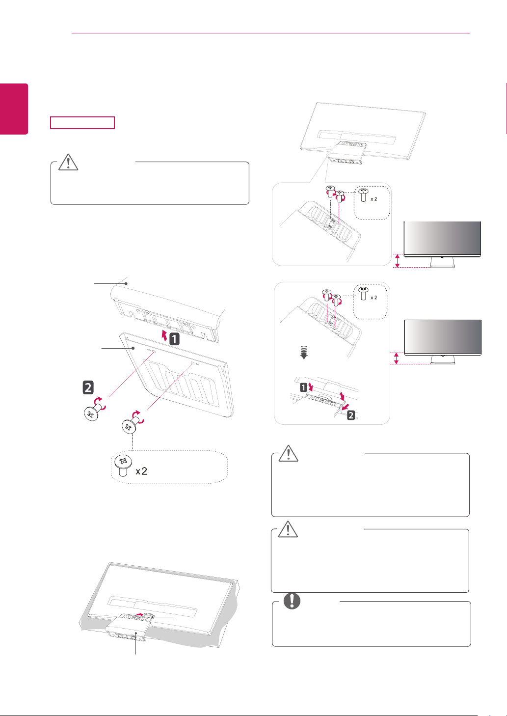
29UB67
Place the screen face down.
34UB67
CAUTION
To protect the screen from scratches, cover
y
the surface with a soft cloth.
Remove a tape on the surface of stand body.
1
Use a tool to attach the stand body as shown
in the figure.
2
Check the position (at the front and rear) of
the stand body, then mount the stand base on
the stand body as shown in the figure.
3
Tighten the screw to the right.
Stand Body
Tape
Stand Body
Stand Base
CAUTION
It may hurt your foot off the stand, so be
careful.
Stand Base
NOTE
You can disassemble the stand in the
y
reverse order of the assembly.

Using the cable holder
ASSEMBLING AND PREPARING
13
29UM67
First, as shown in the illustration,push the
1
cable holder on the stand body, Second ,Fix
the cable holder to stand body.
Stand Body
Put the cables into the cable holder.
2
ENGLISH
ENG
34UM67
Tidy up cables using the cable holder on the stand
base as shown in the illustration.
NOTE
Cables can get caught in the hinge area as
y
shown in the illustration, so be careful when
organizing cables.
CAUTION
Illustrations in this document represent typi-
y
cal procedures, so they may look different
from the actual product.
Applying excessive force when tightening
y
screws may cause damage to the monitor.
Damage caused in this way will not be covered by the product warranty.
Be careful not to hurt your hand on the edges
y
of the screw covers.
Do not carry the monitor upside down by just
y
holding the base. This may cause the monitor to fall off the stand and could result in
personal injury.
When lifting or moving the monitor, do not
y
touch the monitor screen. The force applied
to the monitor screen may cause damage to
it.

14
Installing onto a table
ENGLISH
ENG
1
ASSEMBLING AND PREPARING
Lift the monitor and place it on the table in an
upright position.
Place at least 100 mm away from the wall to
ensure sufficient ventilation.
or
100 mm
100 mm
100 mm
100 mm
100 mm
100 mm
100 mm
100 mm
or
Connect the power adapter to the monitor and
2
then plug the power cord into the wall outlet.
29UB67:Press the knob in “ ” state.
(“ ” Open the power).
Press the joystick button on the bottom of the
3
monitor to turn on the monitor.
CAUTION
Unplug the power cord prior to moving or
y
installing the monitor. There is risk of electric
shock.

Adjusting the stand height
29UB67
Stand the monitor assembled with the stand
1
base in an upright position
34UB67
Head
ASSEMBLING AND PREPARING
15
ENGLISH
ENG
Remove the
2
back of the stand body and then pull out the
locking pin while pressing the head downward.
tape attached to the bottom
Stand Body
Tape
Locking Pin
The height can be adjusted up to
3
Locking Pin
130.0 mm.
130.0 mm
130.0 mm
Head
Locking Pin
CAUTION
Once the pin is removed, it is not necessary
y
to re-insert it to adjust the height.
WARNING
Do not put your fingers or
y
hand between the screen
and the base (chassis) when
adjusting the screen's height.

ASSEMBLING AND PREPARING
16
Adjusting the angle
ENGLISH
ENG
1
2
Place the monitor in an upright position, mount-
ed on the stand base.
Adjust the angle of the screen. The angle of the
screen can be adjusted forwards or backwards
for a comfortable viewing experience.
Rear Side
Front Side
WARNING
To avoid injury to the fingers when adjusting
y
the screen, do not hold the lower part of the
monitor's frame as illustrated below.
Rear Side
Rear Side
Front Side
Front Side
Be careful not to touch or press the screen
y
area when adjusting the angle of the monitor.
 Loading...