

LG 34UM64-P User manual

Owner's Manual
IPS LED MONITOR
(LED MONITOR)
Please read the safety information carefully
before using the product.
IPS LED Monitor (LED Monitor) Model List
25UM64
25UM65
34UM64
34UM65
www.lg.com

TABLE OF CONTENTS
2
TABLE OF CONTENTS
3 LICENSE
ENGLISH
4 ASSEMBLING AND
PREPARING
4 Product Composition
5 Product and Button Description
6 - How to Use the Joystick Button
7 - Input Connector
8 Moving and Lifting the
Monitor
9 Installing the Monitor
9 - Assembling the Stand
12 - Detaching the Stand
15 - Installing on a Table
16 - Adjusting the angle
17 - Tidying up Cables
18 - Installing the Wall Mount Plate
18 - Installing on the Wall
20 - Using the Kensington Lock
24 INSTALLING THE LG
MONITOR SOFTWARE
26 USER SETTINGS
26 Activating the Main Menu
26 - Main Menu Features
27 User Settings
27 - Menu Settings
28 - Ratio
29 - Function
30 - PBP
31 - Picture
32 - Color
33 - Settings
34 - Reset
35 - Reader
36 TROUBLESHOOTING
21 USING THE MONITOR
21 Connecting to a PC
21 - DVI Connection
22 - HDMI Connection
22 - DisplayPort Connection
23 Connecting AV Devices
23 - HDMI Connection
23 Connecting Peripherals
23 - Connecting Headphones
WARNING: This product contains chemicals known to the State of California to cause cancer and birth
defects or other reproductive harm. Wash hands after handling.
38 PRODUCT SPECIFICATION
40 Factory Support Mode
(Preset Mode, DVI-D/HDMI/DisplayPort
PC)
40 HDMI Timing (Video)
40 Power LED
41 PROPER POSTURE
41 Proper Posture for Using the Monitor

LICENSE
3
LICENSE
Each model has different licenses. Visit www.lg.com for more information on the license.
The terms HDMI and HDMI High-Definition Multimedia Interface, and the HDMI
logo are trademarks or registered trademarks of HDMI Licensing LLC in the
United States and other countries.
VESA, VESA logo, DisplayPort compliance logo and DisplayPort
compliance logo for dual-mode source devices are all registered trademarks of
the Video Electronics Standards Association.
ENGLISH
ASSEMBLING AND PREPARING
4
ASSEMBLING AND PREPARING
Product Composition
ENGLISH
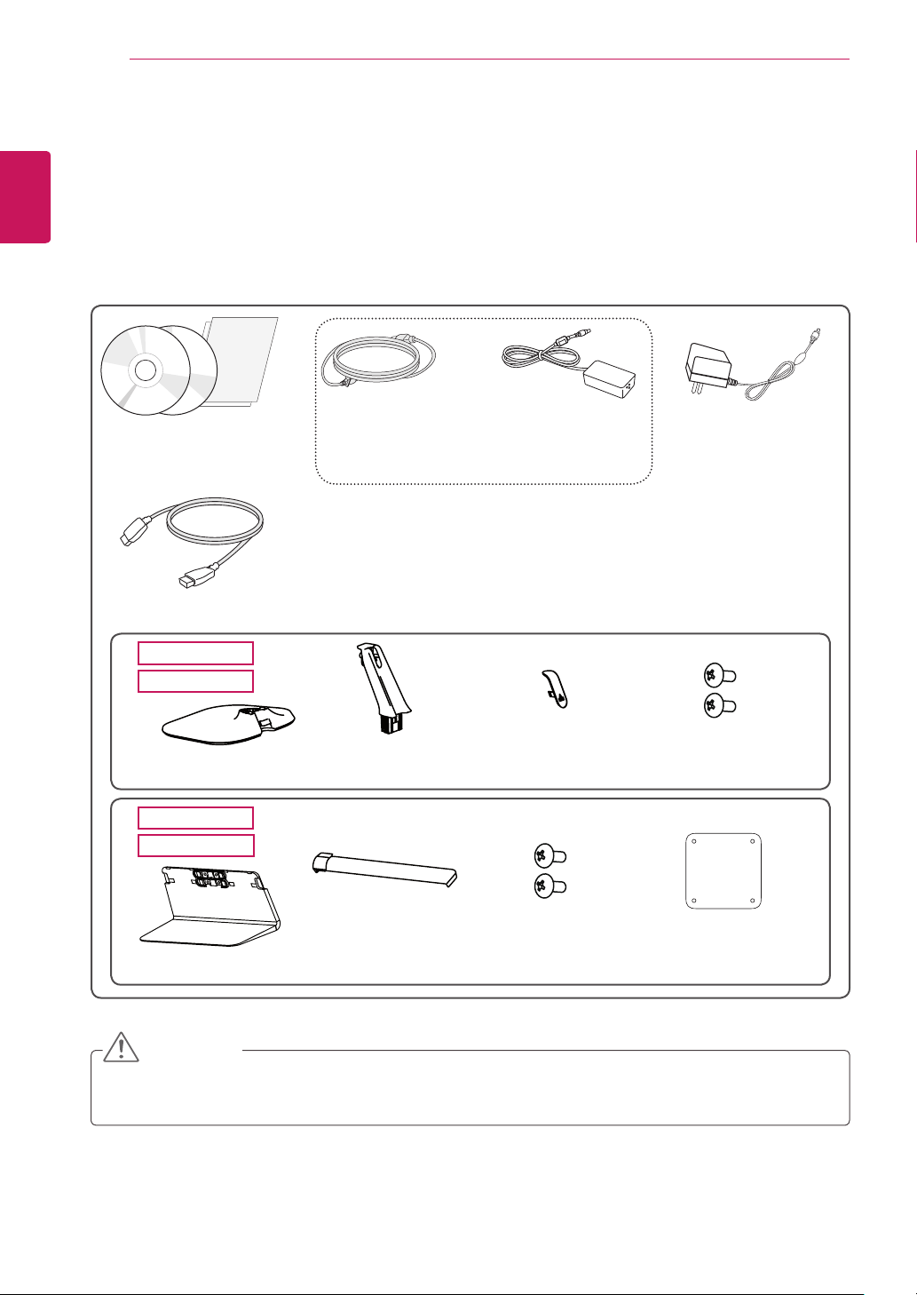
Please check whether all the components are included in the box before using the product. If there are
any missing components, contact the retailer where you purchased the product. Note that the product and
related components may look different from those shown here.
or
CD (Owner's Manual /
Software) / Guides /
Cards
HDMI cable
25UM65
25UM64
Stand Base Stand Body Screw Cover
34UM65
34UM64
Power cord AC/DC Adapter
(Depending upon country)
AC/DC Adapter
(Depending upon
country)
Two Screws
(M4 x 10)
Stand Base Screw Cover
Two Screws
(M4 x 10)
Clear sheet
CAUTION
yAlways use genuine LG components to ensure safety and product performance.
yThe product warranty will not cover damage or injury caused by the use of unauthorized components.

ASSEMBLING AND PREPARING
5
NOTE
yThe components may look different from those illustrated here.
yWithout prior notice, all product information and specifications contained in this manual are subject to
change to improve the performance of the product.
yTo purchase optional accessories, visit an electronics store or an online shopping site, or contact the
retailer from which you purchased the product.
yThe power cord provided may differ depending upon the region.
Product and Button Description
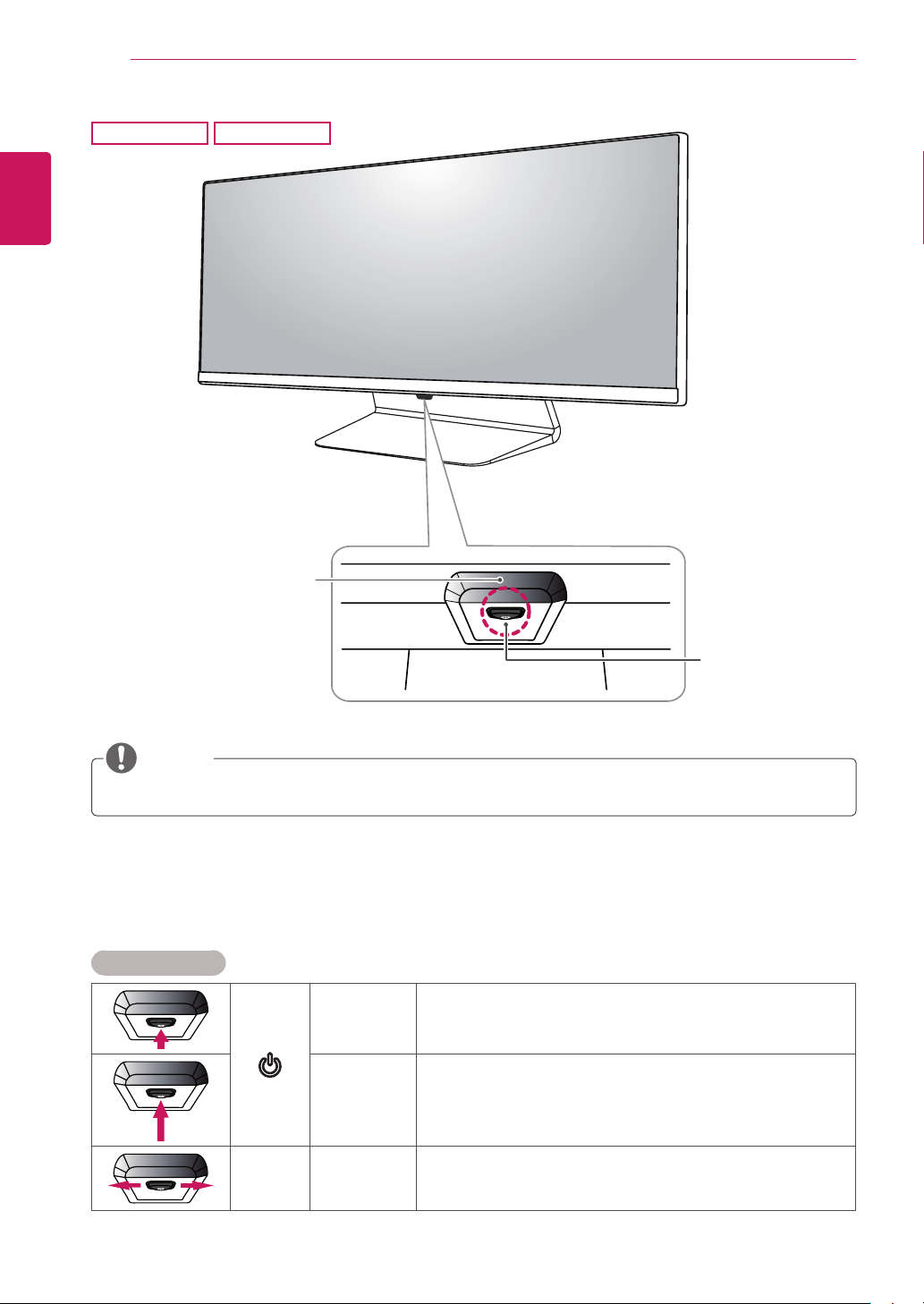
25UM65
25UM64
ENGLISH
Power Indicator
yOn Power on
yOff Power off
NOTE
yThe joystick button is located at the bottom of the monitor.
Joystick
Button
ASSEMBLING AND PREPARING
6
ENGLISH
34UM65
Power Indicator
34UM64
yOn Power on
yOff Power off
Joystick
Button
NOTE
yThe joystick button is located at the bottom of the monitor.
How to Use the Joystick Button
You can easily control the functions of the monitor by pressing the joystick button or moving it left/right with
your finger.
Basic Functions
Press the joystick button once with your finger to turn on the
monitor.
Press and hold the joystick button once with your finger to turn off
the monitor.
You can control the volume by moving the joystick button left/right.
◄/►
Power on
Power off
Volume
Control

Input Connector
IN
25UM65
25UM64
ASSEMBLING AND PREPARING
7
ENGLISH
34UM65
DVI-D IN
34UM64
HDMI IN 2
DP IN
HDMI IN 2
HDMI IN 1
AUDIO IN(PC)
H/P
DC-IN
(19 V )
AUDIO IN
(PC)
H/P
DC-IN
(19 V )
DVI-D IN
DP IN
HDMI IN 1

ASSEMBLING AND PREPARING
8
Moving and Lifting the Monitor
When moving or lifting the monitor, follow these
instructions to prevent the monitor from being
ENGLISH
scratched or damaged and to ensure safe transportation, regardless of its shape or size.
yPlace the monitor in the original box or pack-
ing material before attempting to move it.
yBefore moving or lifting the monitor, discon-
nect the power cord and all other cables.
yHold the bottom and side of the monitor frame
firmly. Do not hold the panel itself.
yWhen moving the monitor, keep it upright and
never turn the monitor on its side or tilt it sideways.
CAUTION
yAvoid touching the monitor screen as much as
possible.
- This may result in damage to the screen or
some of the pixels used to create images.
yWhen holding the monitor, the screen should
face toward you to prevent it from being
scratched.
yWhen transporting the monitor, do not expose
the monitor to shock or excessive vibration.
yIf you use the monitor panel without the stand
base, its joystick button may cause the monitor to become unstable and fall, resulting in
damage to the monitor or human injury. In
addition, this may cause the joystick button to
malfunction.
Installing the Monitor
Assembling the Stand
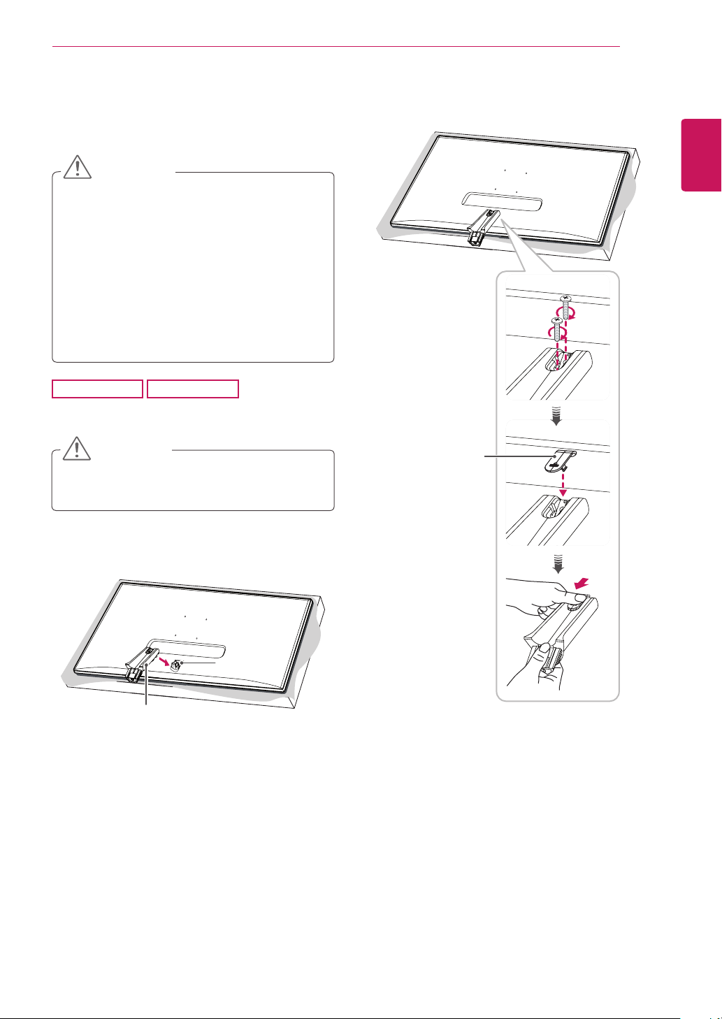
CAUTION
yApplying excessive force when tightening
screws may cause damage to the monitor.
Damage caused in this way will not be covered by the product warranty.
yIf you use the monitor panel without the
stand base, its joystick button may cause the
monitor to become unstable and fall, resulting in damage to the monitor or human injury.
In addition, this may cause the joystick button
to malfunction.
ASSEMBLING AND PREPARING
Tighten two screws into the back of the stand
3
body and close the screw cover.
9
ENGLISH
25UM65
Place the screen face down.
1
25UM64
CAUTION
yTo protect the screen from scratches, cover
the surface with a soft cloth.
Check the direction of the stand body (front,
2
back) and then mount the stand body onto the
stand hinge.
Stand Hinge
Stand Body
Screw Cover

10
4
ENGLISH
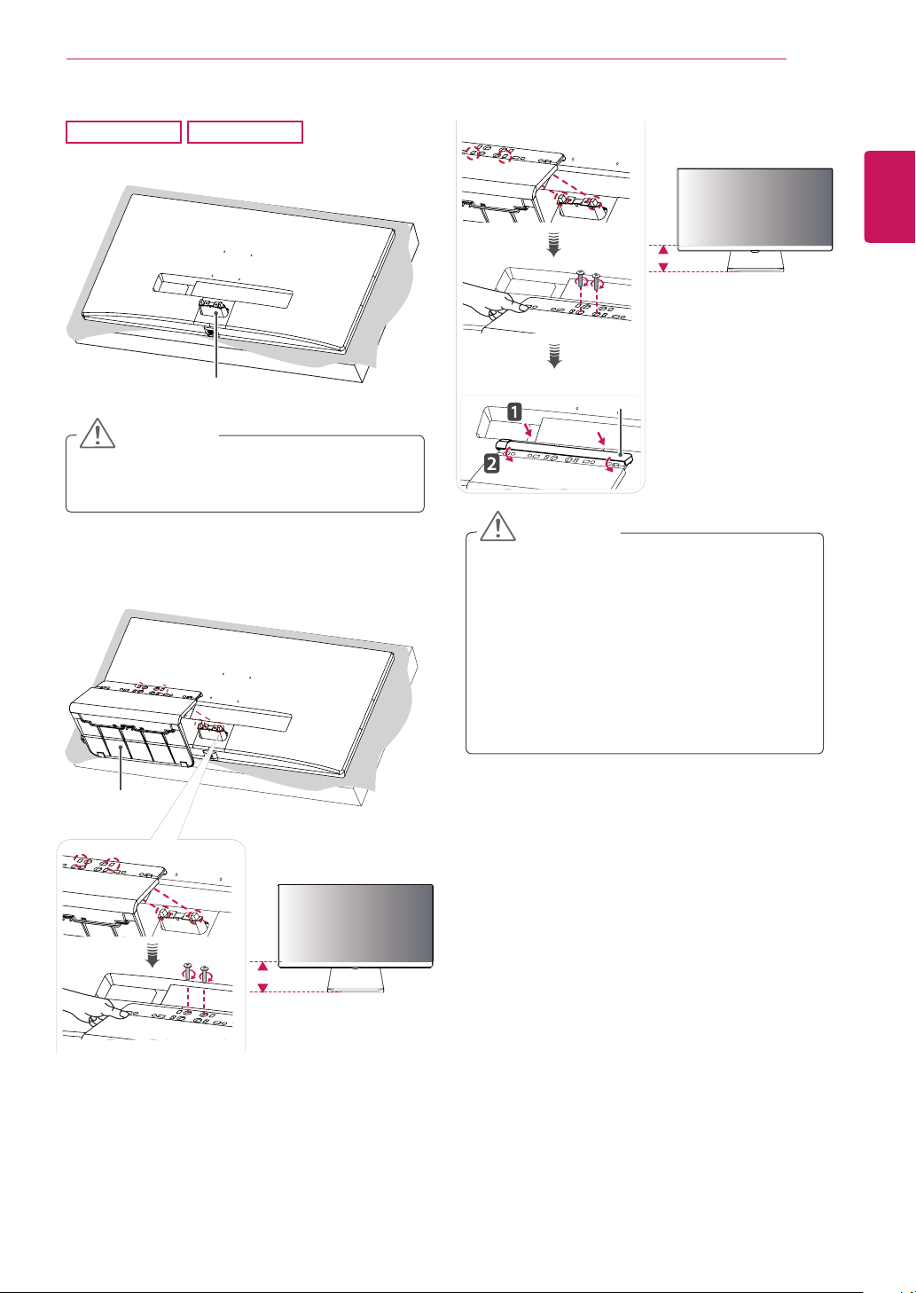
Stand Base
ASSEMBLING AND PREPARING
Fix the stand base to the stand body. Turn the
screws on the stand base to the right.
Stand Body
ASSEMBLING AND PREPARING
11
34UM65
Place the screen face down.
1
34UM64
Stand Hinge
CAUTION
yTo protect the screen from scratches, cover
the surface with a soft cloth.
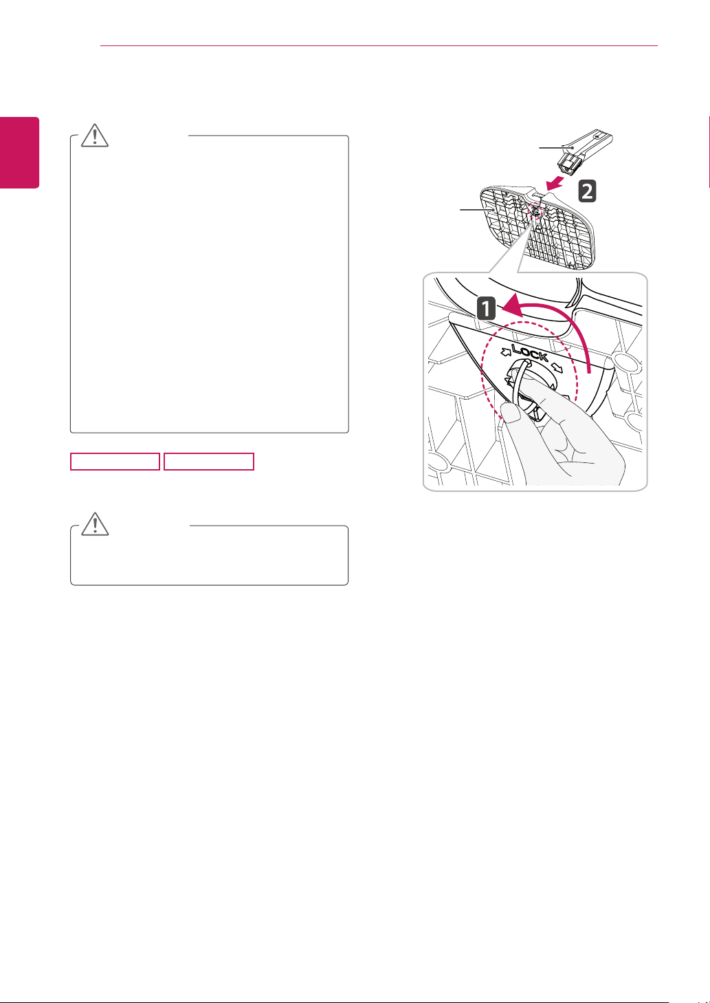
Mount the stand base onto the stand hinge as
2
shown in the illustration. Fix two screws into
the back of the stand base and close the screw
cover.
or
ENGLISH
100 mm
(3.9 inch)
Screw Cover
CAUTION
yThe stand height is adjustable by 20 mm
(0.7 inch).
yWhen tightening the screws after mounting
the stand base onto the stand hinge, be sure
to hold the stand base with your hand. Otherwise, the product may fall, causing personal
injury or damage to the product.
yBe careful not to hurt your hand on the edges
of the screw covers.
Stand Base
120 mm
(4.7 inch)
ASSEMBLING AND PREPARING
12
Detaching the Stand
CAUTION
yIllustrations in this document represent typical
ENGLISH
procedures, so they may look different from
the actual product.
yDo not carry the monitor upside down by just
holding the base. This may cause the monitor
to fall off the stand and could result in personal
injury.
yWhen lifting or moving the monitor, do not
touch the monitor screen. The force applied to
the monitor screen may cause damage to it.
yIf you use the monitor panel without the stand
base, its joystick button may cause the monitor to become unstable and fall, resulting in
damage to the monitor or human injury. In
addition, this may cause the joystick button to
malfunction.
Turn the screws on the stand base to the left to
2
detach the stand base from the stand body.
Stand Body
Stand Base
25UM65
Place the screen face down.
1
25UM64
CAUTION
yTo protect the screen from scratches, cover
the surface with a soft cloth.

Lift up the screw cover to detach the screw
3
cover from the stand body. Remove the screws
from the back of the stand body using a screwdriver and detach the stand body from the
stand hinge as shown in the illustration.
Stand Body
Stand Hinge
ASSEMBLING AND PREPARING
13
ENGLISH
Screw Cover
 Loading...