

Page 1

OWNER’S MANUAL
LED TV*
*LG LED TVs are LCD TVs with LED backlighting.
Please read this manual carefully before operating your set and retain it
for future reference.
LW75**
LY75**
LY76**
www.lg.com
Page 2
2
TABLE OF CONTENTS
ENGLISH
ENG
TABLE OF CONTENTS
3 LICENSES
3 OPEN SOURCE SOFTWARE
NOTICE
4 INSTALLATION PROCEDURE
4 ASSEMBLING AND PREPARING
4 Unpacking
8 Separate purchase
9 Parts and Button
10 - Using the Joystick button
11 Lifting and Moving the TV
12 Setting up the TV
12 - Attaching the Stand
15 Mounting on a table
18 Mounting on a wall
20 Tidying cables
21 MAKING CONNECTIONS
21 Antenna Connection
22 Adapter Connection
22 Satellite Dish Connection
22 LED Clock Connection
23 HDMI Connection
24 MHL Connection
24 Speaker Output Setup
25 Network Setup
25 - Wired network Connection
26 Audio Connection
26 - Digital Optical Audio Connection
26 CI module Connection
27 Headphone Connection
27 USB Connection
28 Euro Scart Connection
29 REMOTE CONTROL
32 TROUBLESHOOTING
33 SPECIFICATIONS
38 IR CODES
39 EXTERNAL CONTROL DEVICE
SETUP
39 RS-232C Setup
39 Type of Connector:
D-Sub 9-Pin Male
40 RS-232C Configurations
41 Communication Parameters
41 Command Reference List
42 Transmission / Receiving Protocol
WARNING
yIf you ignore the warning message, you
may be seriously injured or there is a
possibility of accident or death.
CAUTION
yIf you ignore the caution message, you
may be slightly injured or the product may
be damaged.
31 MAINTENANCE
31 Cleaning your TV
31 - Screen, Frame, Cabinet and Stand
31 - Power Cord
NOTE
yThe note helps you understand and use
the product safely. Please read the note
carefully before using the product.
Page 3
LICENSES / OPEN SOURCE SOFTWARE NOTICE
3
LICENSES
Supported licenses may differ by model. For more information about licenses, visit www.lg.com.
Manufactured under license from Dolby Laboratories. Dolby and the double-D
symbol are trademarks of Dolby Laboratories.
The terms HDMI and HDMI High-Definition Multimedia Interface, and the
HDMI logo are trademarks or registered trademarks of HDMI Licensing LLC in
the United States and other countries.
ABOUT DIVX VIDEO: DivX® is a digital video format created by DivX, LLC, a
subsidiary of Rovi Corporation. This is an official DivX Certified® device that
has passed rigorous testing to verify that it plays DivX video. Visit divx.com for
more information and software tools to convert your files into DivX videos.
ABOUT DIVX VIDEO-ON-DEMAND: This DivX Certified® device must be
registered in order to play purchased DivX Video-on-Demand (VOD) movies.
To obtain your registration code, locate the DivX VOD section in your device
setup menu. Go to vod.divx.com for more information on how to complete your
registration.
“DivX Certified® to play DivX® video up to HD 1080p, including premium
content.”
“DivX®, DivX Certified® and associated logos are trademarks of Rovi
Corporation or its subsidiaries and are used under license.”
“Covered by one or more of the following U.S. patents :
7,295,673; 7,460,668; 7,515,710; 7,519,274”
ENGENGLISH
For DTS patents, see http://patents.dts.com. Manufactured under license from
DTS Licensing Limited. DTS, the Symbol, & DTS and the Symbol together are
registered trademarks, and DTS 2.0+Digital Out is a trademark of DTS, Inc. ©
DTS, Inc. All Rights Reserved.
OPEN SOURCE SOFTWARE NOTICE
To obtain the source code under GPL, LGPL, MPL and other open source licenses, that is contained in this
product, please visit http://opensource.lge.com.
In addition to the source code, all referred license terms, warranty disclaimers and copyright notices are
available for download.
LG Electronics will also provide open source code to you on CD-ROM for a charge covering the cost of
performing such distribution (such as the cost of media, shipping and handling) upon email request to
[email protected]. This offer is valid for three (3) years from the date on which you purchased the
product.
Page 4
ENGLISH
<
<
ENG
4
INSTALLATION PROCEDURE / ASSEMBLING AND PREPARING
NOTE
yImage shown may differ from your TV.
yYour TV’s OSD (On Screen Display) may differ slightly from that shown in this manual.
yThe available menus and options may differ from the input source or product model that you are
using.
yNew features may be added to this TV in the future.
yThe TV can be placed in standby mode in order to reduce the power consumption. And the TV
should be turned off if it will not be watched for some time, as this will reduce energy consumption.
yThe energy consumed during use can be significantly reduced if the level of brightness of the
picture is reduced, and this will reduce the overall running cost.
INSTALLATION PROCEDURE
1 Open the package and make sure all the accessories are included.
2 Attach the stand to the TV set.
3 Connect an external device to the TV set.
4 Make sure the network connection is available.
You can use the TV network functions only when the network connection is made.
ASSEMBLING AND PREPARING
Unpacking
Check your product box for the following items. If there are any missing accessories, contact the local
dealer where you purchased your product. The illustrations in this manual may differ from the actual
product and item.
CAUTION
yDo not use any unapproved items to ensure the safety and product life span.
yAny damage or injuries caused by using unapproved items are not covered by the warranty.
ySome models have a thin film attached on to the screen and this must not be removed.
NOTE
yThe items supplied with your product may vary depending on the model.
yProduct specifications or contents of this manual may be changed without prior notice due to
upgrade of product functions.
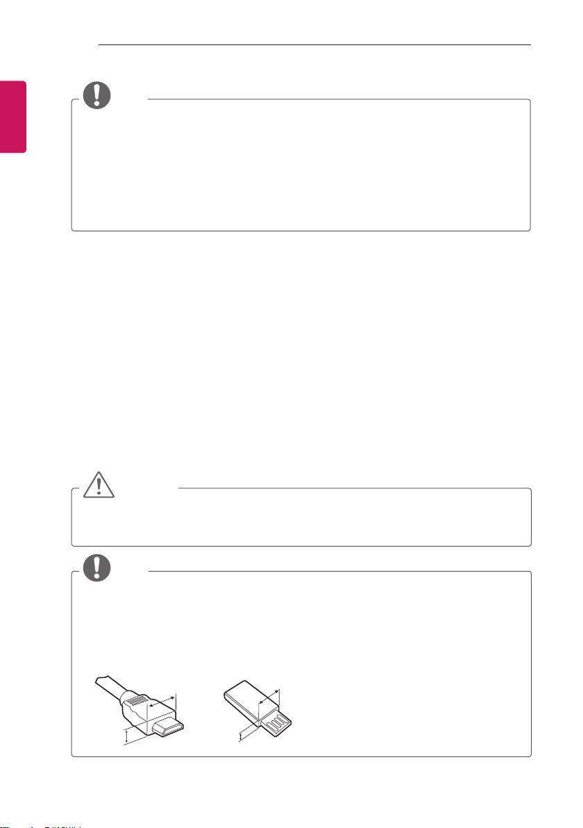
yFor an optimal connection, HDMI cables and USB devices should have bezels less than 10 mm
thick and 18 mm width. Use an extension cable that supports USB 2.0 if the USB cable or USB
FLASH DRIVE does not fit into your TV’s USB port.
B
A
B
*A
10 mm
=
18 mm
*B
A
=
Page 5
ENERGY
SAVING
1 2 3
4 5 6
7 809
LIST
MENU
BACK
ASSEMBLING AND PREPARING
AV MODE
INPUT
TV
FLASHBK
MARK
FAV
P
A
G
3D
CHVOL
E
MUTE
INFO
Q.MENU
ENTER
EXIT
L/R SELECT
FREEZE
RATIO
5
ENGENGLISH
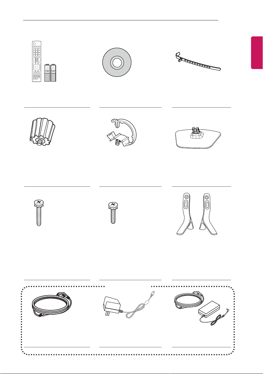
Remote control, Batteries
(AAA)
(See p. 29, 30)
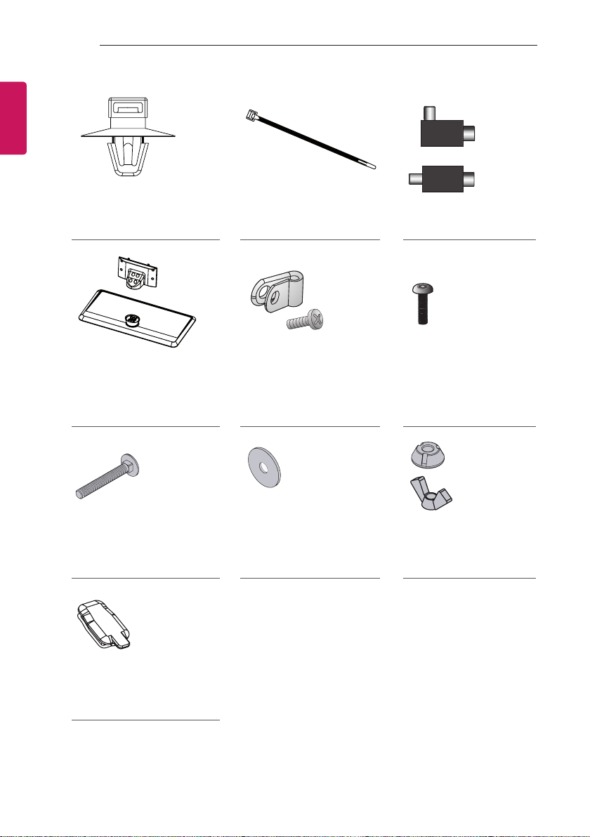
Wall Mount Spacers
2EA
(Only 42LW75**, 42LY75**,
42LY76**)
(See p. 19)
Stand Screws
4EA, M4 x L20
(Only 32LY750*,
42/47/55LY751*, 32LY76**)
6EA, M4 x L20
(Only 32/39LY751*)
(See p. 12, 13, 14)
Owner’s manual Cable Holder
Cable Managements
2EA
(Only LY750*, LY76**)
(See p. 20)
Stand Screws
4EA, M4 x L14
(Only 39/42/47/55LY750*,
42/47/55LY751*,
39/42/47/55LY76**)
(See p. 12, 14)
(Depending on model)
(Depending on model)
(See p. 20)
Stand Base
(Only 22LW75**)
(See p. 12)
Stand Bases
(Only LY750*, LY76**)
(See p. 12)
or
Power cord AC-DC Adapter
(See p. 22)
or
Power Cord/
AC-DC Adapter
(See p. 22)
Page 6
ENGLISH
ENG
6
INSTALLATION PROCEDURE
or
Cable Holders
4EA
(Only 22/28LW75**)
Stand Base/Stand Body
(Only LY751*)
(See p. 13, 14)
Screws for Stand Fixing
2EA
(Depending on model)
(See p. 17)
Cable Managements
2EA
(Only 22/28LW75**)
Power Cord Holder/Screw
1EA
(Only 39/42/47/55LY751*)
(See p. 20)
Washers for Stand Fixing
2EA
(Depending on model)
(See p. 17)
Isolator
(Depending on model)
(See p. 7)
Torx Plus Star-Head
Screws
2EA
(Only LY751*)
(See p. 13, 14)
Nuts for Stand Fixing
2EA
(Depending on model)
(See p. 17)
Rubbers
2EA
(Only LY751*)
(See p. 15)
Page 7
INSTALLATION PROCEDURE
7
NOTE
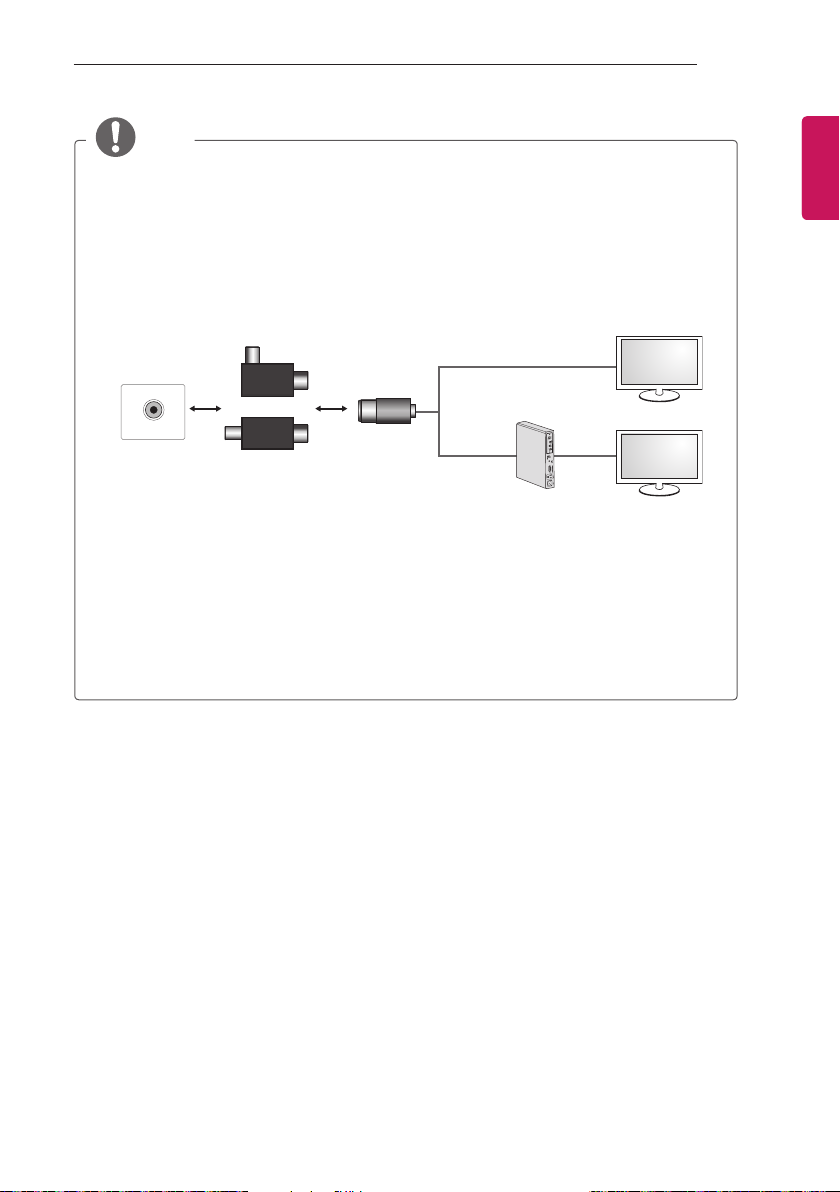
yAntenna Isolator Installation Guide
- Use this to install TV in a place where there is a voltage difference between TV Set and GND of
antenna signal.
»If there is a voltage difference between TV Set and GND of antenna signal, the antenna
contact might be heated and excessive heat might cause an accident.
- You can improve the safety when watching TV by efficiently removing power voltage from TV
antenna. It is recommended to mount the isolator to the wall. If it cannot be mounted to the
wall, mount it on the TV. Avoid disconnecting the antenna Isolator after installation.
- Before starting, be sure that the TV antenna is connected.
Wall
ANTENNA/
CABLE IN
Cable / Antenna
or
Isolator
Connect one end of the isolator to cable/antenna jack and the other to TV set or set-top box.
“Equipment connected to the protective earthing of the building installation through the mains
connection or through other equipment with a connection to protective earthing - and to a cable
distribution system using coaxial cable, may in some circumstances create a re hazard. Connection
to a cable distribution system has therefore to be provided through a device providing electrical
isolation below a certain frequency range (galvanic isolator, see EN 60728-11)”
When applying the RF Isolator, a slight loss of signal sensitivity can occur.
1 Connect to TV.
2 Connect to Set-Top box.
ENGENGLISH
Page 8
8
INSTALLATION PROCEDURE
ENGLISH
ENG
Separate purchase
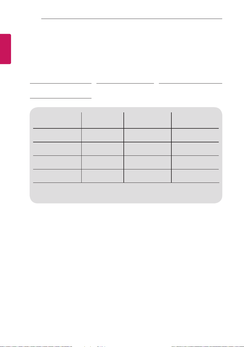
Separate purchase items can be changed or modified for quality improvement without any notification.
Contact your dealer to buy these items.
These devices only work with certain models.
LG Audio Device AN-MR300
LED Clock
LEC-003
Compatibility
LG Audio Device
AN-MR300
Magic Remote
AN-MR500
Magic Remote
LED Clock
LEC-003
The model name or design may be changed depending on the upgrade of product functions,
manufacturer’s circumstances or policies.
Magic Remote
LW75** LY75** LY76**
• • •
• •
•
(Only 32/42LW75**)
AN-MR500
Magic Remote
•
• •
Page 9
Parts and Button
Screen
INSTALLATION PROCEDURE
9
ENGENGLISH
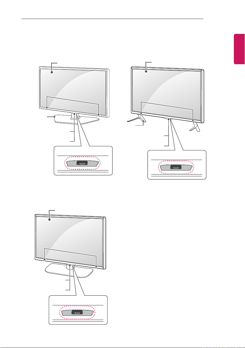
B type : 32/42LW75**, LY750*, LY76**A type : 22/28LW75**
Screen
Stand Base
(Only 22LW75**)
Remote control and
Intelligent1 sensors
Power Indicator
C type : LY751*
Speakers
Joystick Button
Screen
Speakers
Stand Base
(Only LY750*, LY76**)
2
Speakers
Remote control and
Intelligent1 sensors
Power Indicator
Joystick Button
2
Remote control and
Intelligent1 sensors
Power Indicator
Joystick Button
2
Page 10
10
INSTALLATION PROCEDURE
ENGLISH
ENG
1 Intelligent sensor - Adjusts the image quality and brightness based on the surrounding environment.
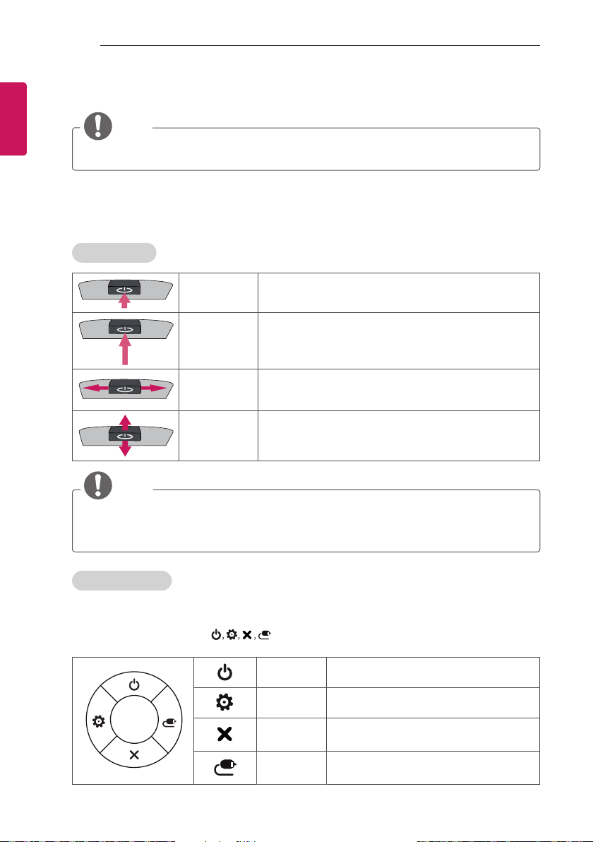
2 Joystick Button - This button is located below the TV screen.
NOTE
yYou can set the power indicator light to on or off by selecting OPTION in the main menus.
Using the Joystick button
You can simply operate the TV functions, pressing or moving the joystick button up, down, left or right.
Basic Functions
Power On
Power Off
Volume Control
Programmes
Control
NOTE
yWhen your finger over the joystick button and push it to the up, down, left or right, be careful not to
press the joystick button. If you press the joystick button first, you can not adjust the volume level
and saved chennels.
When the TV is turned off, place your finger on the joystick
button and press it once and release it.
When the TV is turned on, place your finger on the joystick
button and press it once for a few seconds and release it.
If you place your finger over the joystick button and move it
left or right, you can adjust the volume level you want.
If you place your finger over the joystick button and move it
up or down, you can scrolls through the saved programmes
you want.
Adjusting the Menu
(Only LY76**)
When the TV is turned on, press the joystick button one time.
You can adjust the Menu items(
) moving the joystick button up, down, left or right.
TV Off
Settings Accesses the main menu.
Close
Input List Changes the input source.
Turns the power off.
Closes Clears on-screen displays and returns
to TV viewing.
Page 11

INSTALLATION PROCEDURE
11
Lifting and Moving the TV
Please note the following advice to prevent the
TV from being scratched or damaged and for safe
transportation regardless of its type and size.
CAUTION
yAvoid touching the screen at all times, as
this may result in damage to the screen.
yIt is recommended to move the TV in
the box or packing material that the TV
originally came in.
yBefore moving or lifting the TV,
disconnect the power cord and all cables.
yWhen holding the TV, the screen should
face away from you to avoid damage.
yHold the top and bottom of the TV
frame firmly. Make sure not to hold the
transparent part, speaker, or speaker grill
area.
yWhen transporting a large TV, there
should be at least 2 people.
yWhen transporting the TV by hand,
hold the TV as shown in the following
illustration.
yWhen transporting the TV, do not expose
the TV to jolts or excessive vibration.
yWhen transporting the TV, keep the TV
upright, never turn the TV on its side or
tilt towards the left or right.
yDo not apply excessive pressure to cause
flexing /bending of frame chassis as it
may damage screen.
CAUTION
yWhen handling the TV, be careful not to
damage the protruding joystick button.
(Image shown may differ from your TV.)
ENGENGLISH
Page 12
12
1
2
INSTALLATION PROCEDURE
ENGLISH
ENG
Setting up the TV
Image shown may differ from your TV.
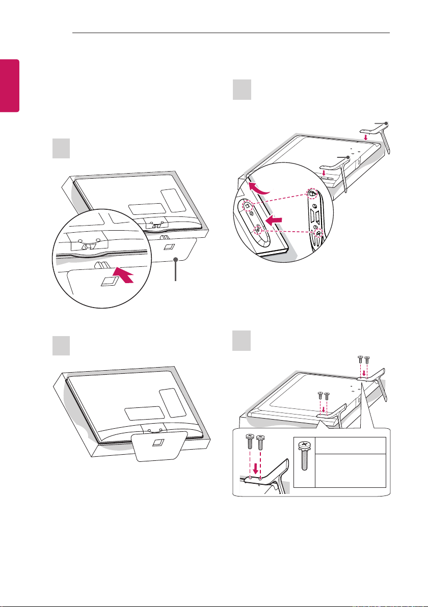
Attaching the Stand
22LW75**
1
Stand Base
2
LY750*, LY76**
1
A stand base
B stand base
1 Attach the stand to the TV using the upper
mounting hole on the back of the TV.
2 Attach the stand to the TV using the lower
connection on the back of the TV.
2
M4 x L14
M4 x L20
(Only 32LY750*,
32LY76**)
4EA
Page 13
INSTALLATION PROCEDURE
13
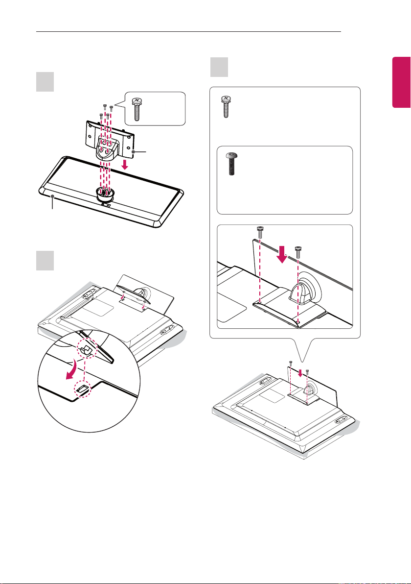
32/39LY751*
1
Stand Base
2
M4 x L20
4EA
Stand Body
3
M4 x L20
2EA
or
Torx Plus Star-Head Screws
2EA
Tighten the two Torx head screws
(supplied with TV) with a Torx Bit Driver
(not supplied with TV).
ENGENGLISH
Page 14

14
wyv{lj{pvuGjv}ly
INSTALLATION PROCEDURE
ENGLISH
ENG
42/47/55LY751*
1
Stand Base
2
M4 x L20
4EA
Stand Body
3
M4 x L14
4EA
or
M4 x L14
2EA
Torx Plus Star-Head Screws
2EA
Tighten the two of these four screws and the
two Torx screws (supplied with TV) to secure
the TV. Tighten the two Torx screws with a
Torx Bit Driver (not supplied with TV).
Page 15
INSTALLATION PROCEDURE
15
CAUTION
yWhen attaching the stand to the TV
set, place the screen facing down on a
cushioned table or flat surface to protect
the screen from scratches.
yMake sure that the screws are fastened
completely. (If they are not fastened
securely enough, the TV may tilt forward
after being installed.)
Do not use too much force and over
tighten the screws; otherwise screw may
be damaged and not tighten correctly.
NOTE
yRemove the stand before installing the
TV on a wall mount by performing the
stand attachment in reverse.
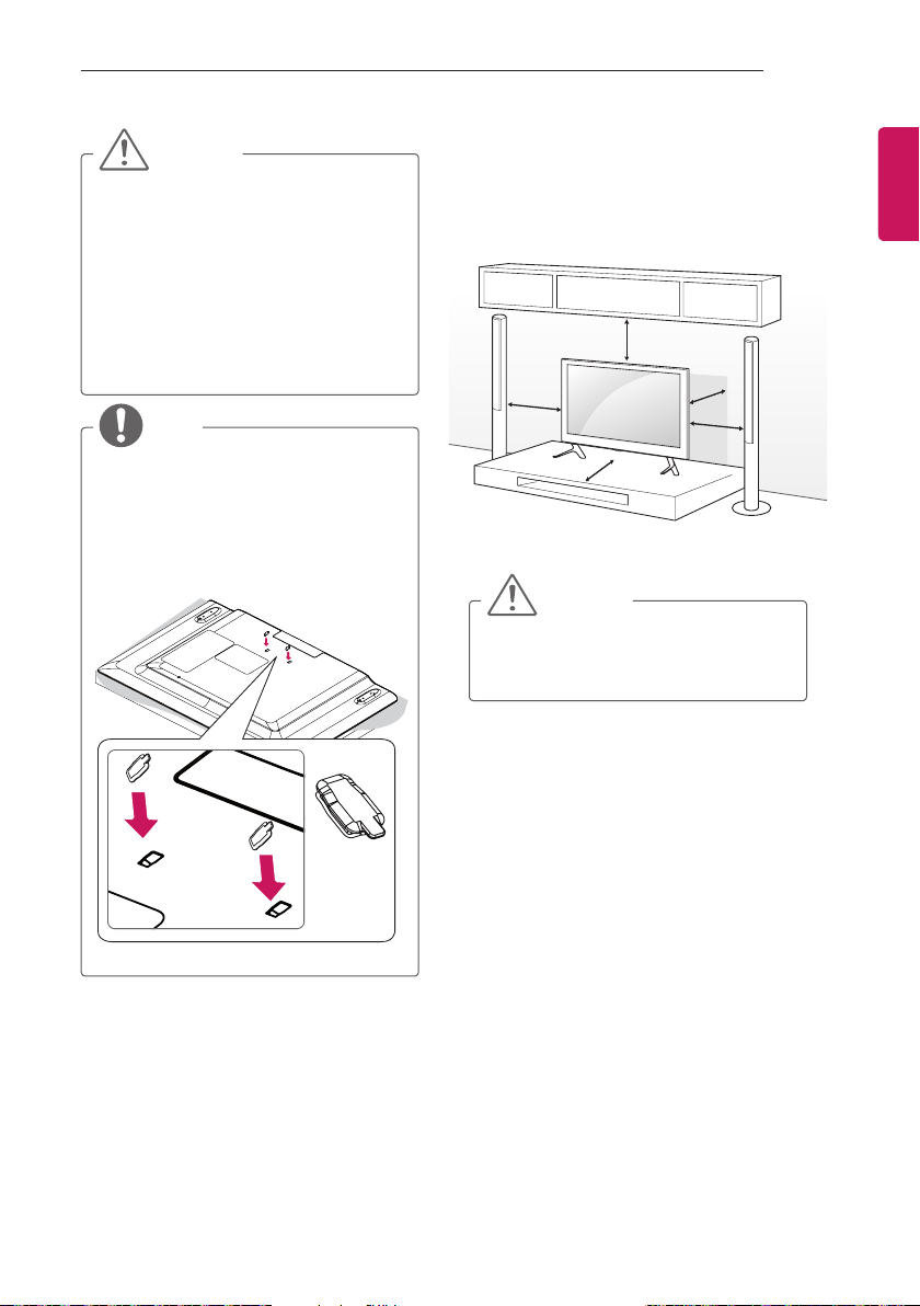
yThe Rubber will protect the opening
from accumulating dust and dirt. When
installing the wall mounting bracket, use
the Rubber. (Only LY751*)
Mounting on a table
1 Lift and tilt the TV into its upright position on
a table.
- Leave a 10 cm (minimum) space from
the wall for proper ventilation.
10 cm
10 cm
10 cm
2 Connect the power cord to a wall outlet.
CAUTION
yDo not place the TV near or on sources
of heat, as this may result in fire or other
damage.
10 cm
10 cm
ENGENGLISH
Rubber
2EA
Page 16
16
INSTALLATION PROCEDURE
ENGLISH
ENG
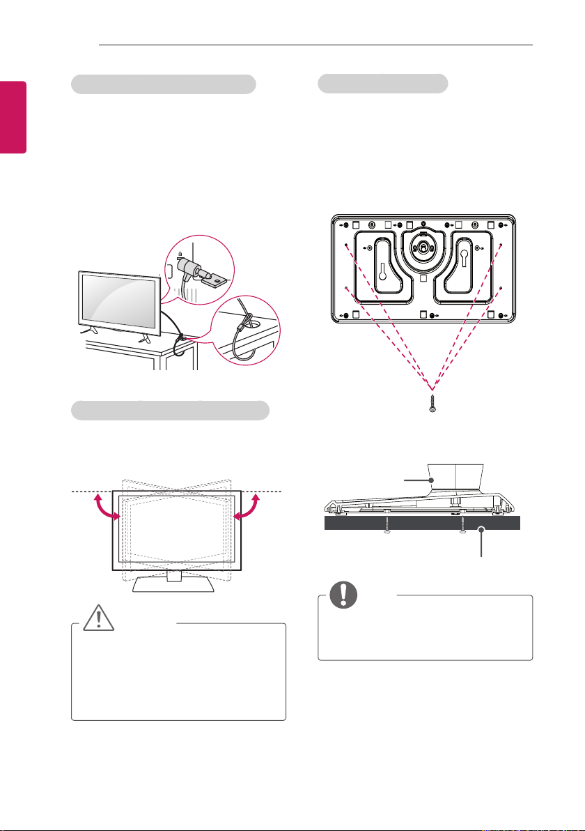
Using the Kensington security system
(This feature is not available for all models.)
yImage shown may differ from your TV.
The Kensington security system connector is
located at the rear of the TV. For more information
of installation and using, refer to the manual
provided with the Kensington security system or
visit http://www.kensington.com.
Connect the Kensington security system cable
between the TV and a table.
Adjusting the angle of the TV to suit view
(Only LY751*)
Swivel 20 degrees to the left or right and adjust
the angle of the TV to suit your view.
Attaching the TV to a desk
(Depending on model)
The TV should be attached to a desk so it cannot
be pulled in a forward/backward direction,
potentially causing injury or damaging the
product.
A type )
4-Screws
(Not supplied with TV)
Stand
20˚20˚
CAUTION
yWhen adjusting the angle of the product,
watch out for your fingers.
»Personal injury may occur if hands
or fingers are pinched. If the product
is tilted too much, it may fall, causing
damage or injury.
Desk
NOTE
yScrew : M5 x L (*L: Table depth + 8~10
mm)
ex) Table depth: 15 mm, Screw: M5 x 25
Page 17
INSTALLATION PROCEDURE
17
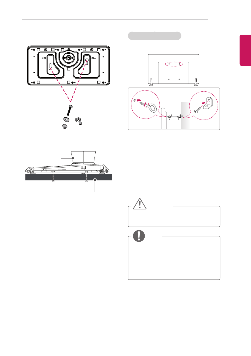
B type )
2-Screws for Stand Fixing, 2-Washers for Stand
Fixing, 2-Nuts for Stand Fixing
(Supplied with TV)
Stand
Desk
Securing the TV to a Wall
(This feature is not available for all models.)
1 Insert and tighten the eye-bolts, or TV
brackets and bolts on the back of the TV.
- If there are bolts inserted at the eyebolts position, remove the bolts first.
2 Mount the wall brackets with the bolts to the
wall.
Match the location of the wall bracket and the
eye-bolts on the rear of the TV.
3 Connect the eye-bolts and wall brackets
tightly with a sturdy rope.
Make sure to keep the rope horizontal with
the at surface.
CAUTION
yMake sure that children do not climb on
or hang on the TV.
ENGENGLISH
NOTE
yUse a platform or cabinet that is strong
and large enough to support the TV
securely.
yBrackets, bolts and ropes are not
provided. You can obtain additional
accessories from your local dealer.
Page 18
18
INSTALLATION PROCEDURE
ENGLISH
ENG
Mounting on a wall
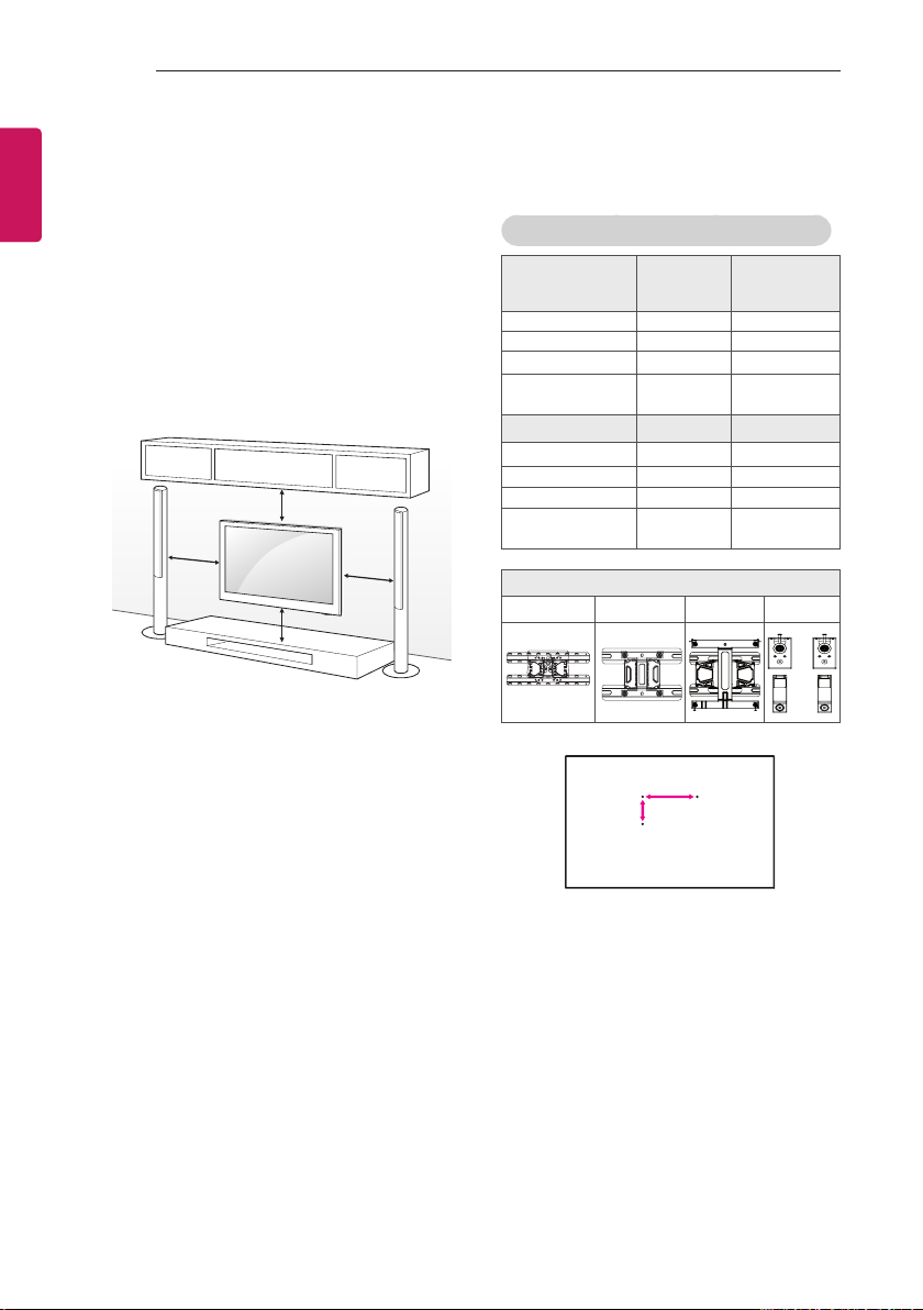
Attach an optional wall mount bracket at the rear
of the TV carefully and install the wall mount
bracket on a solid wall perpendicular to the
floor. When you attach the TV to other building
materials, please contact qualified personnel.
LG recommends that wall mounting be performed
by a qualified professional installer.
We recommend the use of LG’s wall mount
bracket.
When you do not use LG’s wall mount bracket,
please use a wall mount bracket where the device
is adequately secured to the wall with enough
space to allow connectivity to external devices.
10 cm
10 cm
10 cm
10 cm
Make sure to use screws and wall mount
bracket that meet the VESA standard. Standard
dimensions for the wall mount kits are described
in the following table.
Separate purchase (Wall Mounting Bracket)
Model
VESA (A x B) 200 x 200
Standard screw M6
Number of screws 4
Wall mount
bracket
Model
VESA (A x B) 75 x 75
Standard screw M4 X L10
Number of screws
Wall mount
bracket
LSW140B LSW240B LSW440B MSW240
32/39LY76**
32/39LY75**
32LW75**
LSW240B
MSW240
22LW75**
LSW140B LSW140B
Wall mount bracket
4
42/47/55LY76**
42/47/55LY75**
42LW75**
400 x 400
M6
4
LSW440B
MSW240
28LW75**
100 x 100
M4 X L10
4
A
B
Page 19
INSTALLATION PROCEDURE
19
CAUTION
yDisconnect the power first, and then
move or install the TV. Otherwise electric
shock may occur.
yIf you install the TV on a ceiling or slanted
wall, it may fall and result in severe injury.
Use an authorised LG wall mount and
contact the local dealer or qualified
personnel.
yDo not over tighten the screws as this
may cause damage to the TV and void
your warranty.
yUse the screws and wall mounts that
meet the VESA standard. Any damages
or injuries by misuse or using an
improper accessory are not covered by
the warranty.
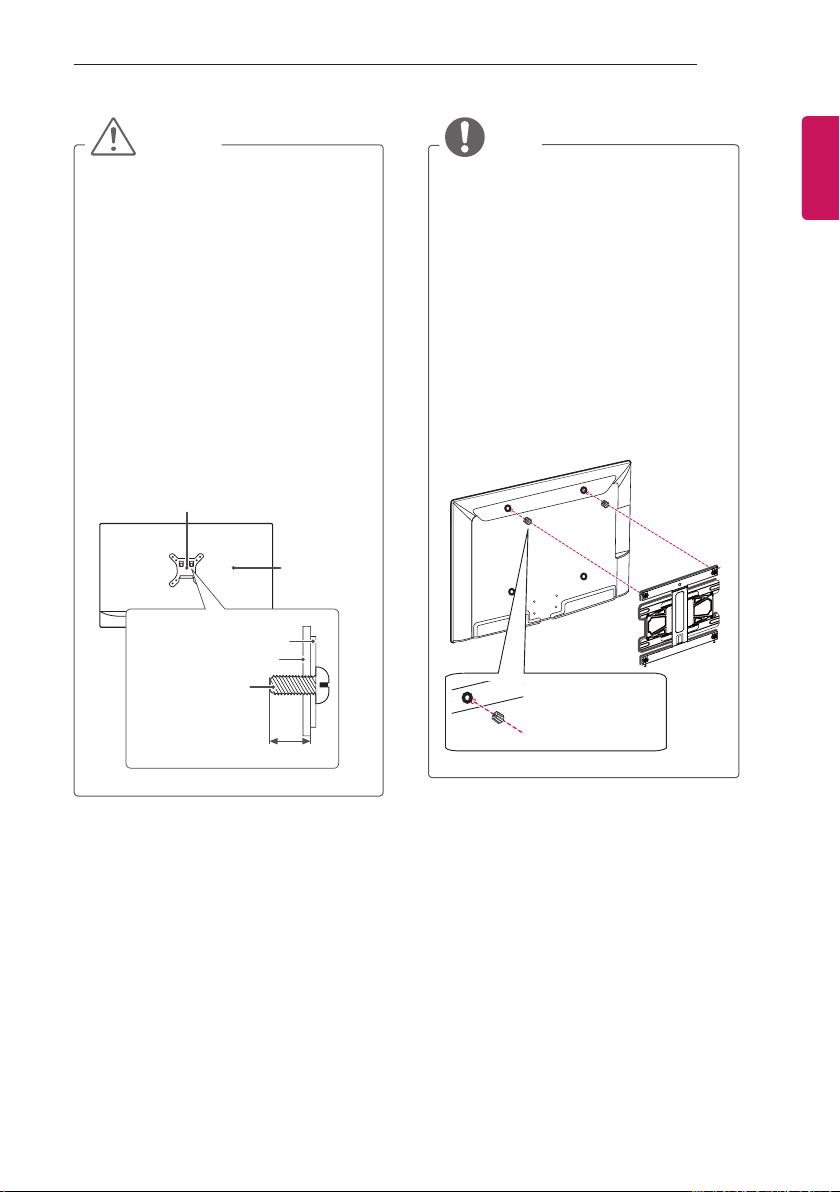
yScrew length from outer surface of back
cover should be under 8 mm. (Only
22/28LW75**)
Wall mount Pad
Back Cover
Wall mount Pad
Back Cover
Standard screw
: M4 x L10
NOTE
yUse the screws that are listed on the
VESA standard screw specifications.
yThe wall mount kit includes an installation
manual and necessary parts.
yThe wall mount bracket is not provided.
You can obtain additional accessories
from your local dealer.
yThe length of screws may differ
depending on the wall mount. Make sure
to use the proper length.
yFor more information, refer to the manual
supplied with the wall mount.
yWhen attaching a wall mounting bracket
to the TV, insert the wall mount spacers
into the TV wall mount holes to adjust the
vertical angle of the TV. (Only 42LW75**,
42LY75**, 42LY76**)
Wall Mount Spacer
ENGENGLISH
Max.8 mm
Page 20
20
INSTALLATION PROCEDURE
ENGLISH
ENG
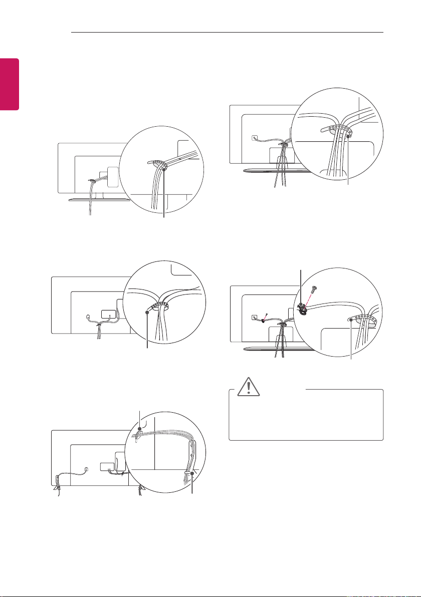
Tidying cables
Image shown may differ from your TV.
(Only 22LW75**)
1 Gather and bind the cables with the cable
holder.
Cable Holder
(Only 28/32/42LW75**)
1 Gather and bind the cables with the cable
holder.
(Only 32LY751*)
1 Gather and bind the cables with the cable
holder.
Cable Holder
(Only 39/42/47/55LY751*)
1 Install the power cord holder and power cord.
It will help prevent the power cable from
being removed by accident.
2 Gather and bind the cables with the cable
holder.
Power Cord Holder/Screw
Cable Holder
(Only LY750*, LY76**)
1 Gather and bind the cables with the cable
holder.
2 Fix the Cable Management rmly to the TV.
Cable Holder
Cable Management
Cable Holder
CAUTION
yDo not move the TV by holding the cable
holder, as the cable holder may break,
and injuries and damage to the TV may
occur.
Page 21
MAKING CONNECTIONS
21
MAKING CONNECTIONS
This section on MAKING CONNECTIONS mainly
uses diagrams for the 42LY750* models.
Connect various external devices to the TV
and switch input modes to select an external
device. For more information on external device’s
connection, refer to the manual provided with
each device.
Available external devices are: HD receivers,
DVD players, VCRs, audio systems, USB storage
devices, PC, gaming devices, and other external
devices.
NOTE
yThe external device connection may differ
from the model.
yConnect external devices to the TV
regardless of the order of the TV port.
yIf you record a TV program on a DVD
recorder or VCR, make sure to connect
the TV signal input cable to the TV
through a DVD recorder or VCR. For
more information on recording, refer to
the manual provided with the connected
device.
yRefer to the external equipment’s manual
for operating instructions.
yIf you connect a gaming device to the TV,
use the cable supplied with the gaming
device.
yIn PC mode, there may be noise
associated with the resolution, vertical
pattern, contrast or brightness. If noise is
present, change the PC output to another
resolution, change the refresh rate to
another rate or adjust the brightness and
contrast on the PICTURE menu until the
picture is clear.
yIn PC mode, some resolution settings
may not work properly depending on the
graphics card.
yOnly a USB storage device is
recognizable.
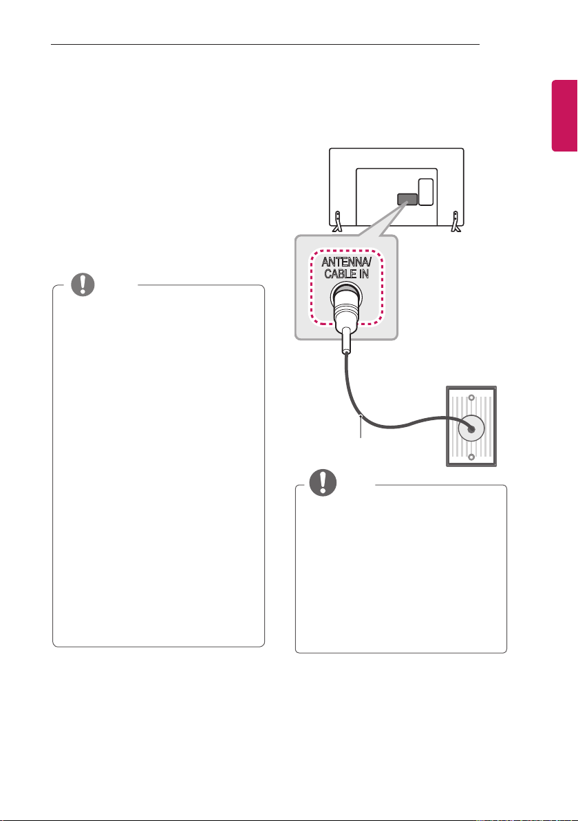
Antenna Connection
Connect the TV to a wall antenna socket with an
RF cable (75 Ω).
ANTENNA/
CABLE IN
Wall Antenna
Socket
(*Not Provided)
NOTE
yUse a signal splitter to use more than 2
TVs.
yIf the image quality is poor, install a signal
amplifier properly to improve the image
quality.
yIf the image quality is poor with an
antenna connected, try to realign the
antenna in the correct direction.
yAn antenna cable and converter are not
supplied.
ySupported DTV Audio: MPEG, Dolby
Digital, Dolby Digital Plus, HE-AAC
ENGENGLISH
Page 22
22
DC-IN
(19V )
LNB
Satellite IN
13/18 V
700mA Max
CLOCK
MAKING CONNECTIONS
ENGLISH
ENG
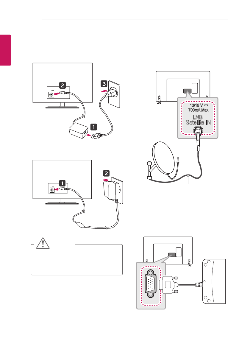
Adapter Connection
(Only 22/28LW75**)
DC-IN
(19V )
AC-DC Adapter
or
AC-DC Adapter
Satellite Dish Connection
(Only satellite models)
Connect the TV to a satellite dish to a satellite
socket with a satellite RF cable (75 Ω).
Satellite
Dish
(*Not Provided)
LED Clock Connection
(Only 32/42LW75**, LY75**, LY76**)
This TV can be connected to a LED Clock via the
CLOCK port.
CAUTION
yPlease be sure to connect the TV to the
AC-DC power adapter before connecting
the TV’s power plug to a wall power
outlet.
LED Clock
(*Not Provided)
Page 23
MAKING CONNECTIONS
HDMI
23
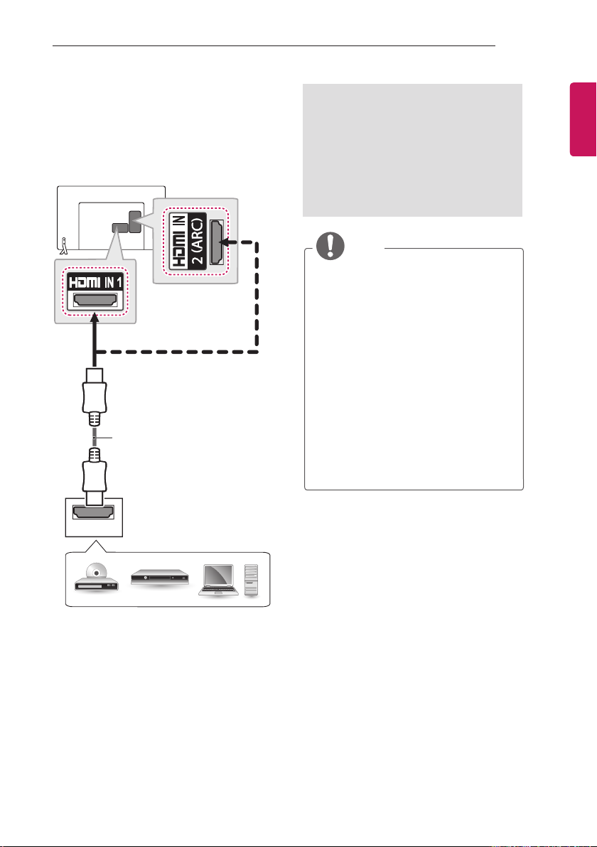
HDMI Connection
Transmits the digital video and audio signals from
your PC to the TV. Connect the PC and the TV
with the HDMI cable as shown. Choose any HDMI
input port to connect. It does not matter which
port you use.
(*Not Provided)
ARC (Audio Return Channel)
yAn external audio device that supports
SIMPLINK and ARC must be connected
using HDMI IN 1 (ARC) or HDMI IN 2
(ARC) port.
yWhen connected with a high-speed
HDMI cable, the external audio device
that supports ARC outputs optical SPDIF
without additional optical audio cable and
supports the SIMPLINK function.
NOTE
yIt is recommended to use the TV with
the HDMI connection for the best image
quality.
yUse the latest High Speed HDMI™ Cable
with CEC (Customer Electronics Control)
function.
yHigh Speed HDMI™ Cables are tested
to carry an HD signal up to 1080p and
higher.
ySupported HDMI Audio format :
Dolby Digital (32 KHz, 44.1 KHz, 48
KHz),
PCM (32 KHz, 44.1 KHz, 48 KHz, 96
KHz, 192 KHz),
DTS supported. (44.1 KHz, 48KHz - Only
LY76**),
DTS not supported. (Only LW75**,
LY75**)
ENGENGLISH
DVD / Blu-Ray / HD Cable Box / HD STB / PC
Page 24
24
SPEAKER OUT
MAKING CONNECTIONS
ENGLISH
ENG
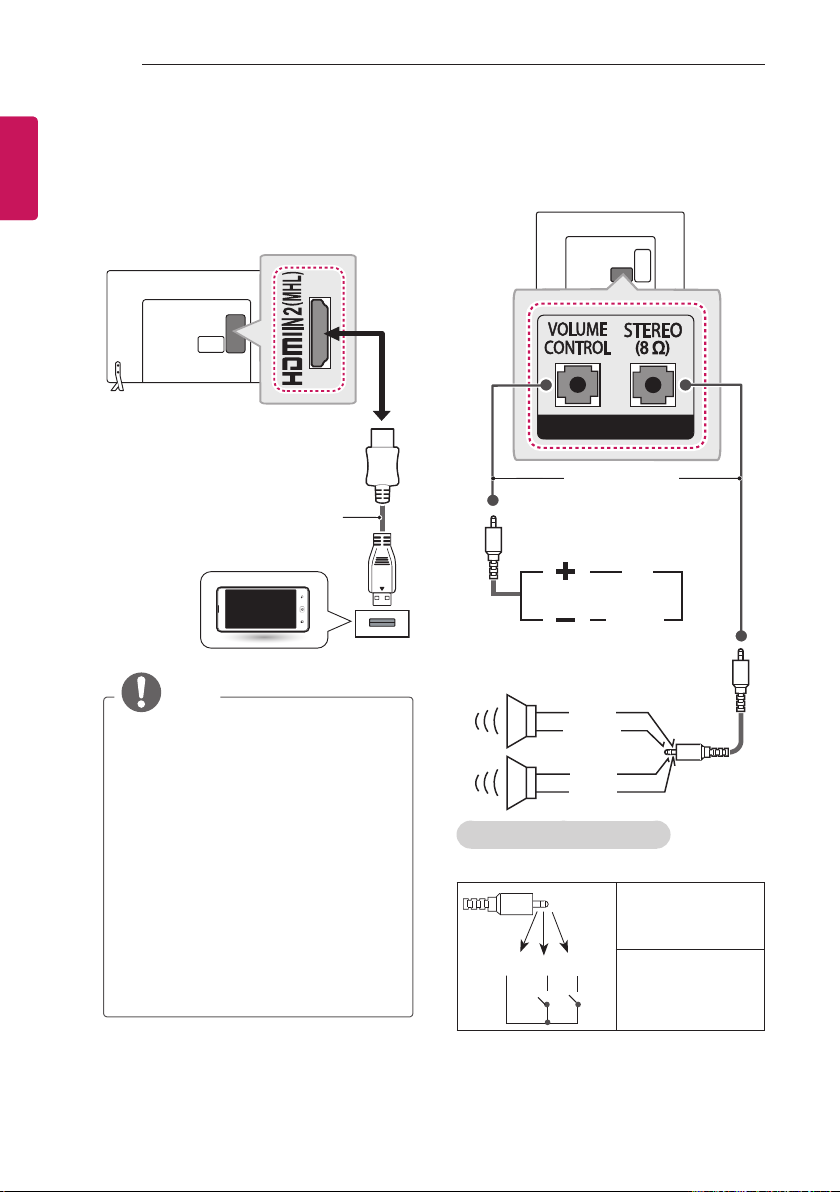
MHL Connection
(Only LY76**)
Mobile High-definition Link (MHL) is an interface
for transmitting digital audiovisual signals from
mobile phones to television sets.
MHL passive cable
(*Not Provided)
Mobile phone
NOTE
yConnect the mobile phone to the HDMI
IN 2 (MHL) port to view the phone
screen on the TV.
yThe MHL passive cable is needed to
connect the TV and a mobile phone.
yThis only works for the MHL-enabled
phone.
ySome applications can be operated by
the remote control.
yFor some mobile phones supporting
MHL, you can control with the Magic
Remote.
yRemove the MHL passive cable from the
TV when:
»the MHL function is disabled
»your mobile device is fully charged in
standby mode
Speaker Output Setup
Connect the external speaker to the SPEAKER
OUT jack on the TV.
(*Not Provided)
Control port for Speaker out
UP
DOWN
GND
RIGHT
LEFT
GND
Method of Volume control port
* Cable Spec.
Each Up/ Down pin is
pulled to 3.3V with
CPU GPIO.
GND / Up / Down
CPU detects
transition from 3.3V
to GND level for volume control.
Page 25
MAKING CONNECTIONS
LAN
1
2
AUX LAN
LAN
1
25
Network Setup
Wired network Connection
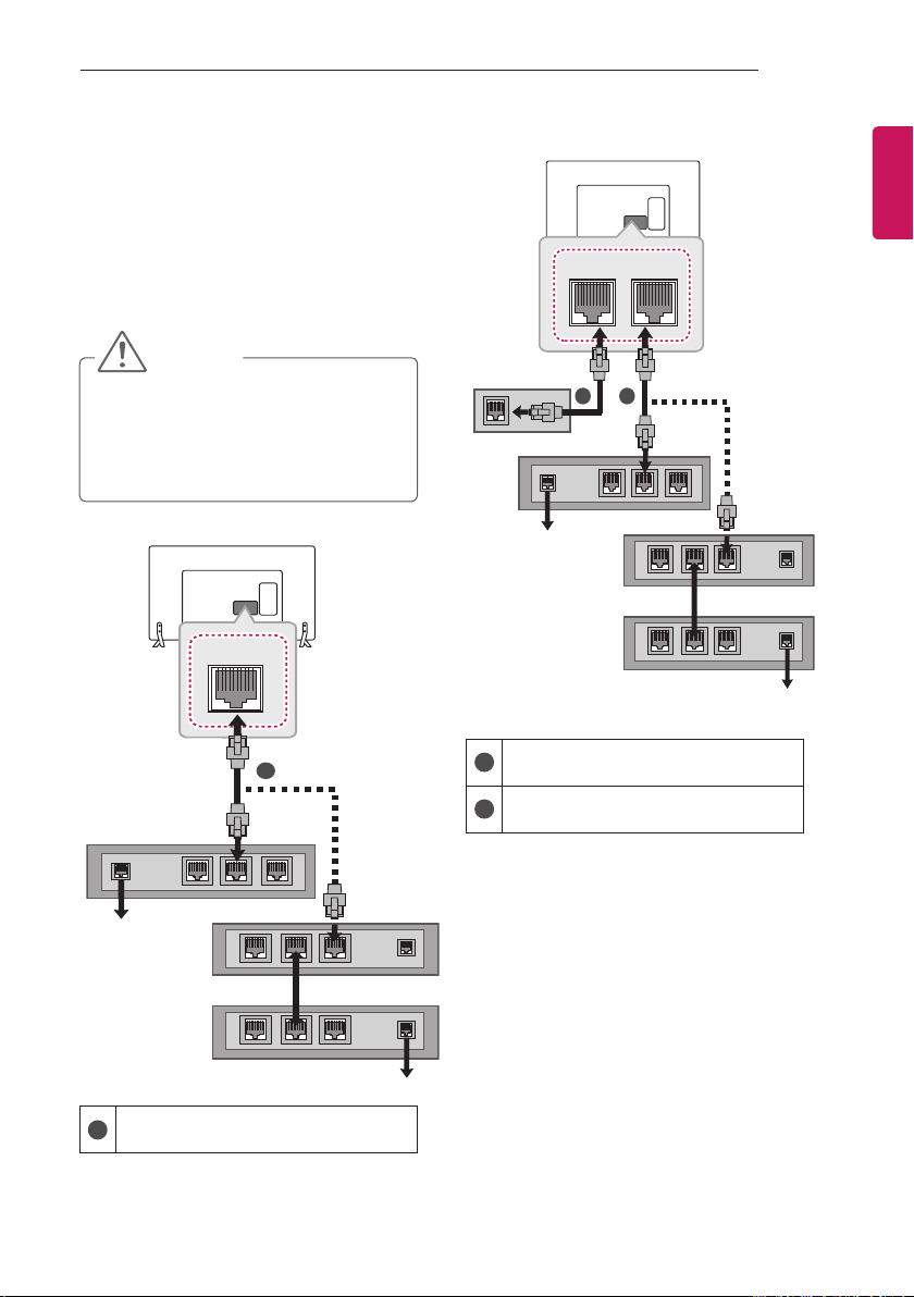
This TV can be connected to a Pro:Centric server
via the LAN port. After making the physical connection, the TV needs to be set up for network
communication.
Connect the LAN port of the Modem or Router
from Pro:Centric server to the LAN port on the TV.
CAUTION
yDo not connect a modular phone cable to
the LAN port.
ySince there are various connection
methods, please follow the specifications
of your telecommunication carrier or
internet service provider.
(Only 22/28LW75**)
(*Not Provided)
Broadband Modem
(Only 32/42LW75**, LY75**, LY76**)
(*Not Provided)
Broadband Modem
Pro:Centric Server
Connect the LAN port of the Modem or
1
Router to the LAN port on the TV.
Connect the LAN port of the PC to the AUX
2
LAN port on the TV.
(*Not Provided)
Pro:Centric Server
ENGENGLISH
Router
Broadband Modem
Pro:Centric Server
1
Pro:Centric Server
Connect the LAN port of the Modem or
Router to the LAN port on the TV.
Router
Broadband Modem
Page 26
26
MAKING CONNECTIONS
ENGLISH
ENG
Audio Connection
You may use an optional external audio system
instead of the built-in speaker.
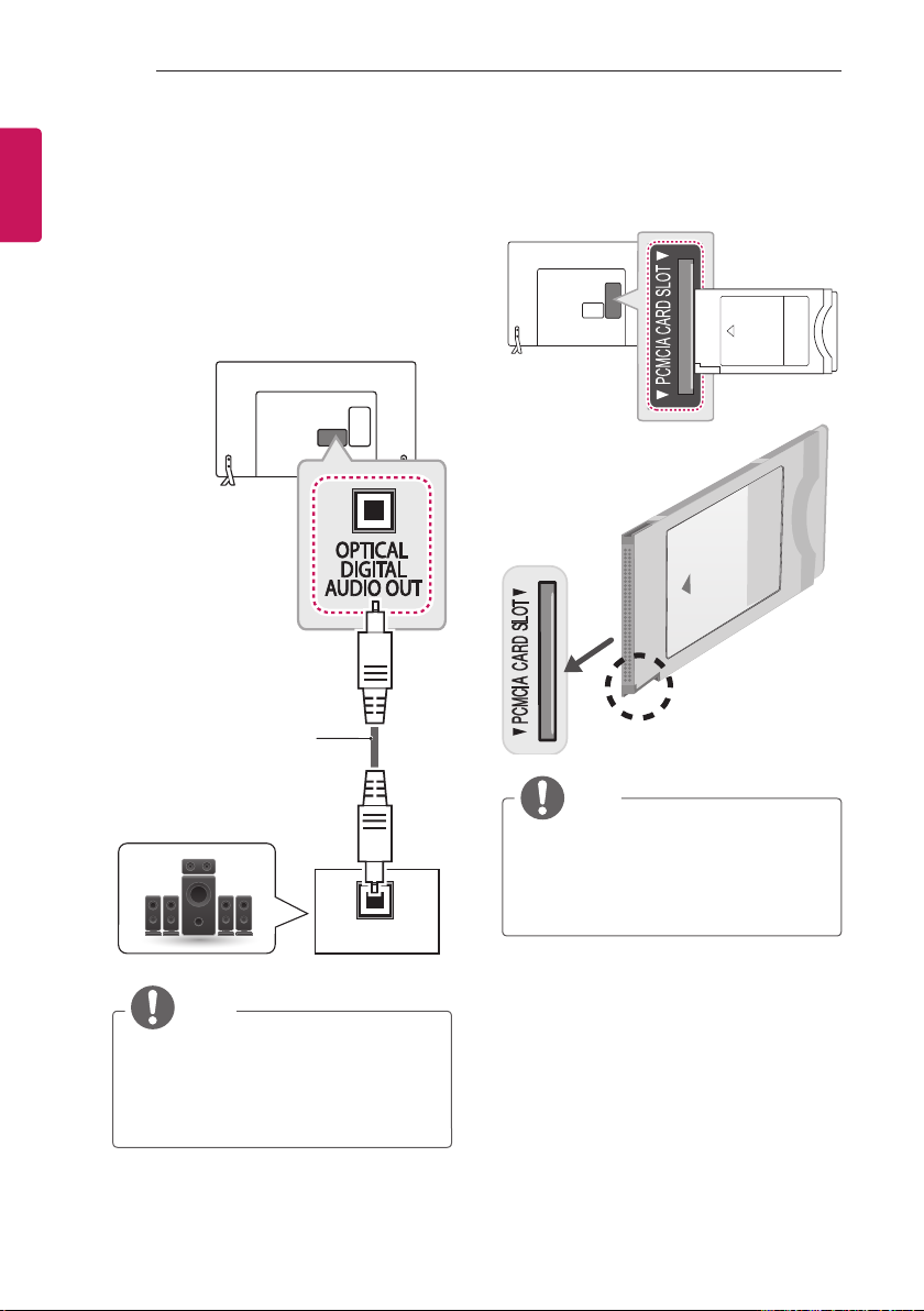
Digital Optical Audio Connection
Transmits a digital audio signal from the TV to an
external device. Connect the external device and
the TV with the optical audio cable as shown.
(*Not Provided)
CI module Connection
View the encrypted (pay) services in digital TV
mode. This feature is not available in all countries.
(*Not Provided)
OPTICAL
AUDIO IN
Digital Audio System
NOTE
yDo not look into the optical output port.
Looking at the laser beam may damage
your vision.
yAudio with ACP (Audio Copy Protection)
function may block digital audio output.
NOTE
yCheck if the CI module is inserted into the
PCMCIA card slot in the right direction. If
the module is not inserted properly, this
can cause damage to the TV and the
PCMCIA card slot.
Page 27
MAKING CONNECTIONS
H/P OUT
27
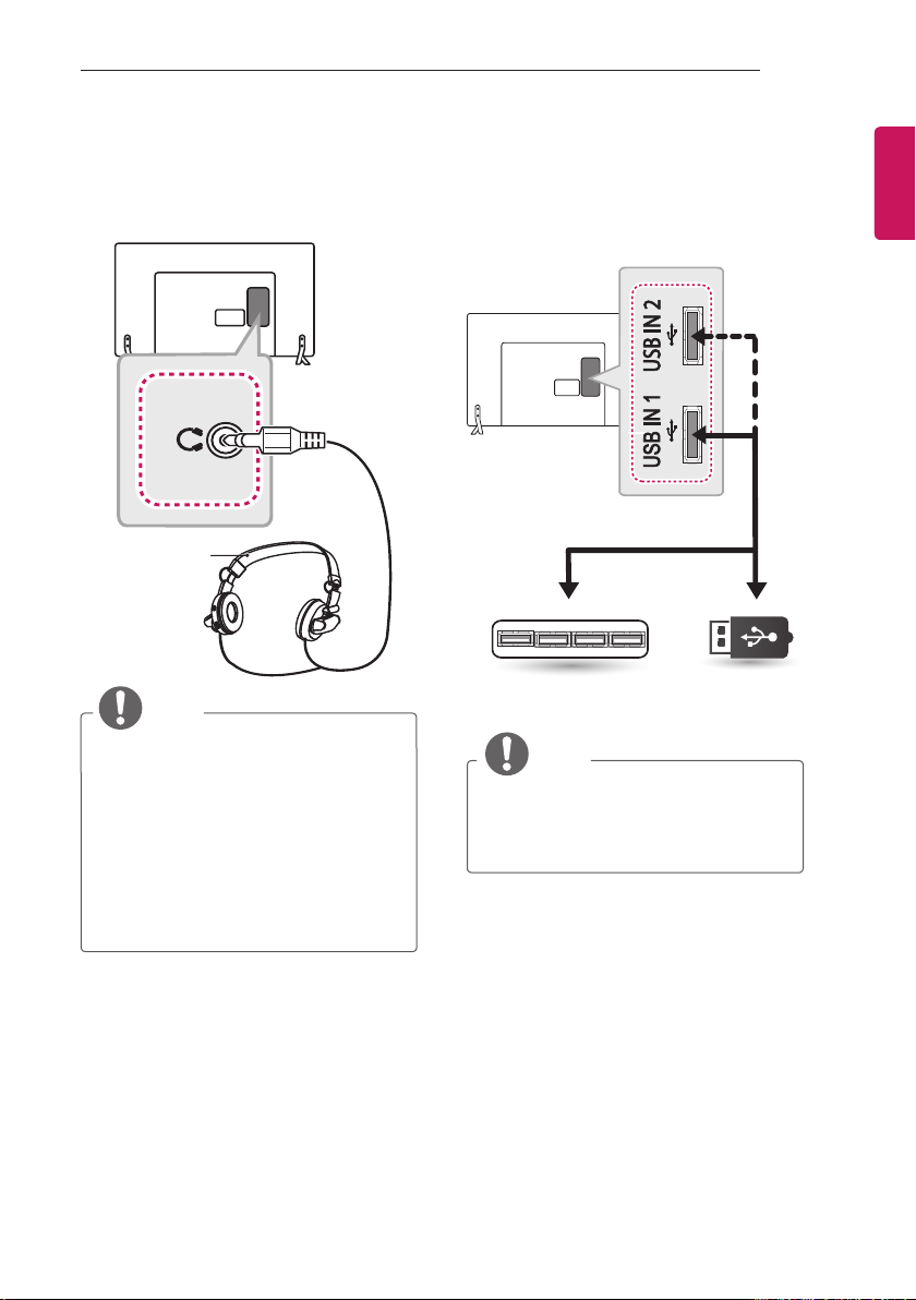
Headphone Connection
Transmits the headphone signal from the TV to
an external device. Connect the external device
and the TV with the headphone as shown.
(*Not Provided)
NOTE
yAUDIO menu items are disabled when
connecting a headphone.
yWhen changing AV MODE with a
headphone connected, the change is
applied to video but not to audio.
yOptical Digital Audio Out is not available
when connecting a headphone.
yHeadphone impedance: 16 Ω
yMax audio output of headphone: 9 mW to
15 mW
yHeadphone jack size: 0.35 cm
USB Connection
Connect a USB storage device such as s USB
flash memory, external hard drive or a USB
memory card reader to the TV and access the
SmartShare menu to use various multimedia files.
HUB
(*Not Provided)
NOTE
ySome USB Hubs may not work. If a USB
device connected using a USB Hub is not
detected, connect it to the USB port on
the TV directly.
USB
(*Not Provided)
ENGENGLISH
Page 28
28
MAKING CONNECTIONS
ENGLISH
ENG
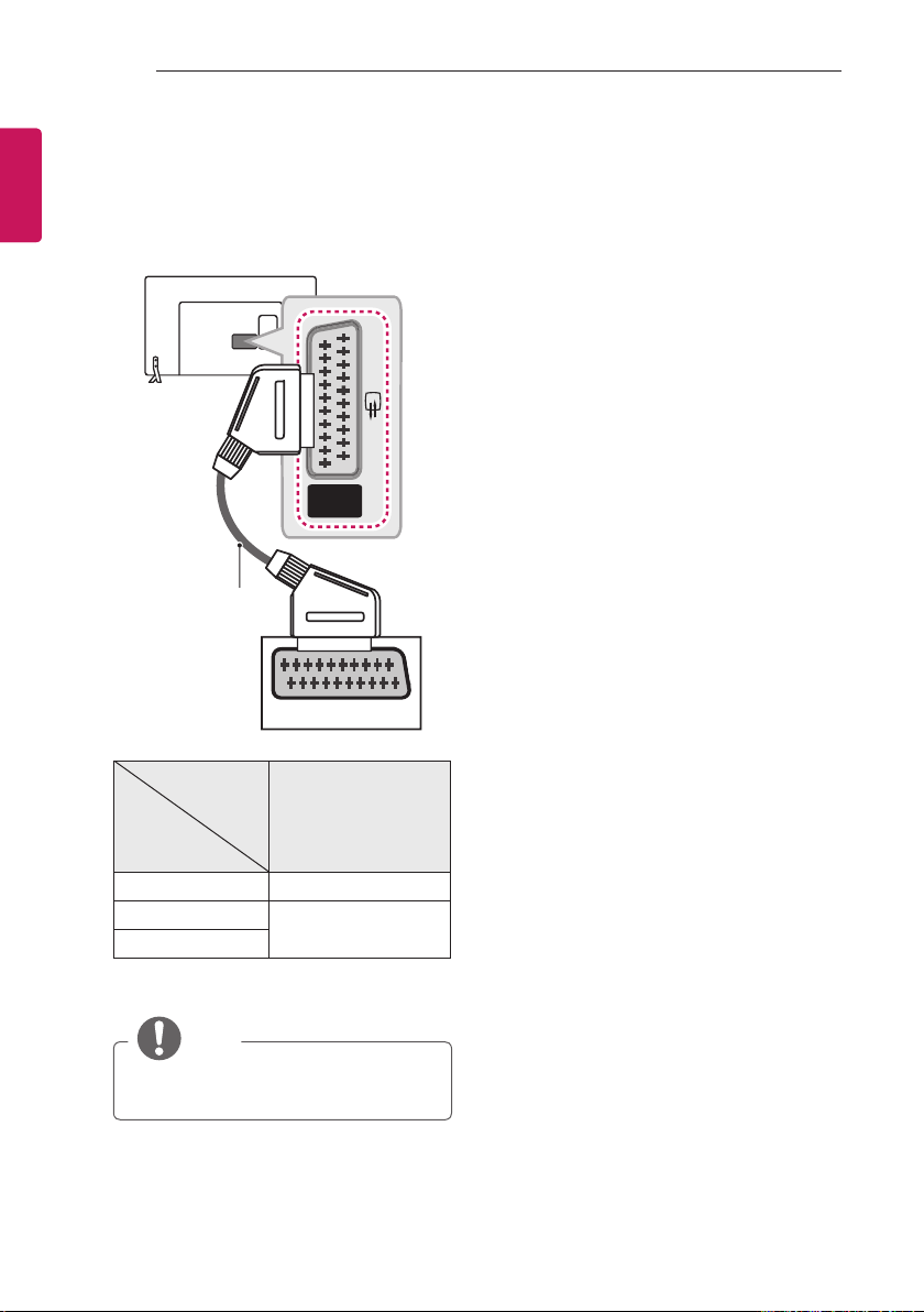
Euro Scart Connection
Transmits the video and audio signals from
an external device to the TV set. Connect the
external device and the TV set with the euro scart
cable as shown.
AV
IN / OUT
(*Not Provided)
AUDIO / VIDEO
Output
Type
Current
input mode
Digital TV Digital TV
Analogue TV, AV
HDMI
1 TV Out : Outputs Analogue TV or Digital TV
signals.
AV
1
)
(TV Out
Analogue TV
NOTE
yAny Euro scart cable used must be signal
shielded.
Page 29
REMOTE CONTROL
RAD
ENERGY
SAVING
RATIO
MUTE
Q.MENUADALARM
OK
GUIDE
INFO
EXIT
PORTAL
29
REMOTE CONTROL
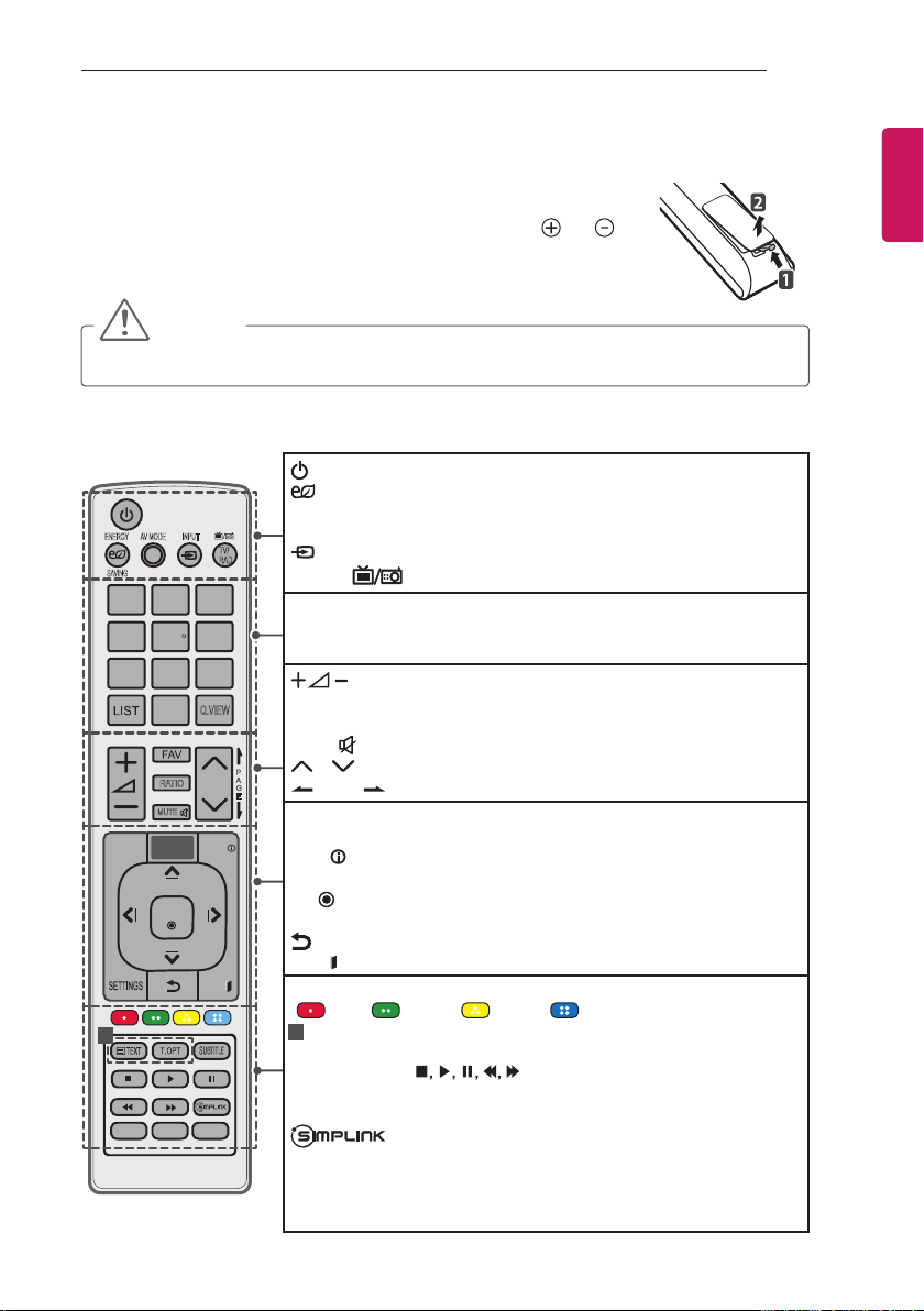
The descriptions in this manual are based on the buttons on the remote control.
Please read this manual carefully and use the TV correctly. To replace batteries,
open the battery cover, replace batteries (1.5 V AAA) matching the
to the label inside the compartment, and close the battery cover. To remove the
batteries, perform the installation actions in reverse.
CAUTION
yDo not mix old and new batteries, as this may damage the remote control.
Make sure to point the remote control toward the remote control sensor on the TV.
(Only LW75**, LY75**)
(POWER) Turns the TV on or off.
ENERGY SAVING Adjusts the brightness of the screen to reduce
energy consumption.
AV MODE Selects an AV mode.
INPUT Changes the input source.
TV/RAD
Selects Radio, TV and DTV programme.
Number buttons Enters numbers.
LIST Accesses the saved programme list.
Q.VIEW Returns to the previously viewed programme.
Adjusts the volume level.
FAV Accesses your favourite programme list.
RATIO Resizes an image.
MUTE
Mutes all sounds.
P
A
G
E
P Scrolls through the saved programmes.
PAGE Moves to the previous or next screen.
GUIDE Shows programme guide.
PORTAL Displays and removes hotel interactive menu.
INFO
Views the information of the current programme and screen.
Navigation buttons (up/down/left/right) Scrolls through menus or options.
OK Selects menus or options and conrms your input.
SETTINGS Accesses the main menus.
(BACK) Returns to the previous level.
EXIT
Clears on-screen displays and return to TV viewing.
Coloured buttons These access special functions in some menus.
(
: Red, : Green, : Yellow, : Blue)
Teletext buttons These buttons are used for teletext.
1
SUBTITLE Recalls your preferred subtitle in digital mode.
Control buttons (
SmartShare menus or the SIMPLINK compatible devices (USB or
SIMPLINK).
Accesses the AV devices connected with the HDMI cable
through HDMI-CEC. Opens the SIMPLINK menu.
Q.MENU Accesses the Quick menus.
AD By Pressing AD button, audio descriptions function will be enabled.
ALARM Sets the alarm function. (Depending on model)
1 2 3
4 506
7 8 9
1
AV MODE INPUT
TV/
Q.VIEW
P
ENGENGLISH
and ends
) Controls the Premium contents,
Page 30
30
RAD
ENERGY
SAVING
RATIO
MUTE
Q.MENU AD ALARM
OK
GUIDE
INFO
EXIT
PORTAL
REMOTE CONTROL
ENGLISH
ENG
(Only LY76**)
AV MODE INPUT
1 2 3
4 506
7 8 9
1
TV/
Q.VIEW
P
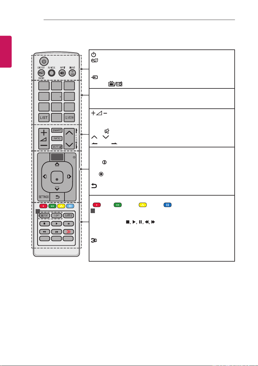
(POWER) Turns the TV on or off.
ENERGY SAVING Adjusts the brightness of the screen to reduce
energy consumption.
AV MODE Selects an AV mode.
INPUT Changes the input source.
TV/RAD
Selects Radio, TV and DTV programme.
Number buttons Enters numbers.
LIST Accesses the saved programme list.
Q.VIEW Returns to the previously viewed programme.
Adjusts the volume level.
SMART Accesses the Home menus.
RATIO Resizes an image.
MUTE
P
A
G
E
Mutes all sounds.
P Scrolls through the saved programmes.
PAGE Moves to the previous or next screen.
GUIDE Shows programme guide.
PORTAL Displays and removes hotel interactive menu.
INFO
Views the information of the current programme and screen.
Navigation buttons (up/down/left/right) Scrolls through menus or options.
OK Selects menus or options and conrms your input.
SETTINGS Accesses the main menus.
(BACK) Returns to the previous level.
EXIT Clears on-screen displays and return to TV viewing.
Coloured buttons These access special functions in some menus.
(
: Red, : Green, : Yellow, : Blue)
Teletext buttons These buttons are used for teletext.
1
SUBTITLE Recalls your preferred subtitle in digital mode.
Control buttons (
) Controls the Premium contents,
SmartShare menus or the SIMPLINK compatible devices (USB or
SIMPLINK).
Used for viewing 3D video. (Depending on model)
Q.MENU Accesses the Quick menus.
AD By Pressing AD button, audio descriptions function will be enabled.
ALARM Sets the alarm function.
Page 31
MAINTENANCE
31
MAINTENANCE
Cleaning your TV
Clean your TV regularly to keep the best performance and to extend the product lifespan.
CAUTION
yMake sure to turn the power off and disconnect the power cord and all other cables first.
yWhen the TV is left unattended and unused for a long time, disconnect the power cord from the
wall outlet to prevent possible damage from lightning or power surges.
Screen, Frame, Cabinet and Stand
yTo remove dust or light dirt, wipe the surface with a dry, clean, and soft cloth.
yTo remove major dirt, wipe the surface with a soft cloth dampened in clean water or a diluted mild
detergent. Then wipe immediately with a dry cloth.
CAUTION
yAvoid touching the screen at all times, as this may result in damage to the screen.
yDo not push, rub, or hit the screen surface with your fingernail or a sharp object, as this may result
in scratches and image distortions.
yDo not use any chemicals as this may damage the product.
yDo not spray liquid onto the surface. If water enters the TV, it may result in fire, electric shock, or
malfunction.
Power Cord
Remove the accumulated dust or dirt on the power cord regularly.
ENGENGLISH
Page 32
32
TROUBLESHOOTING
ENGLISH
ENG
TROUBLESHOOTING
The software version can be updated for improvement in performance. Customer needs to ensure the
compatibility of customer’s equipment with LGE software. If needed, please consult with LGE and upload
revised software version according to the guidance provided by LGE.
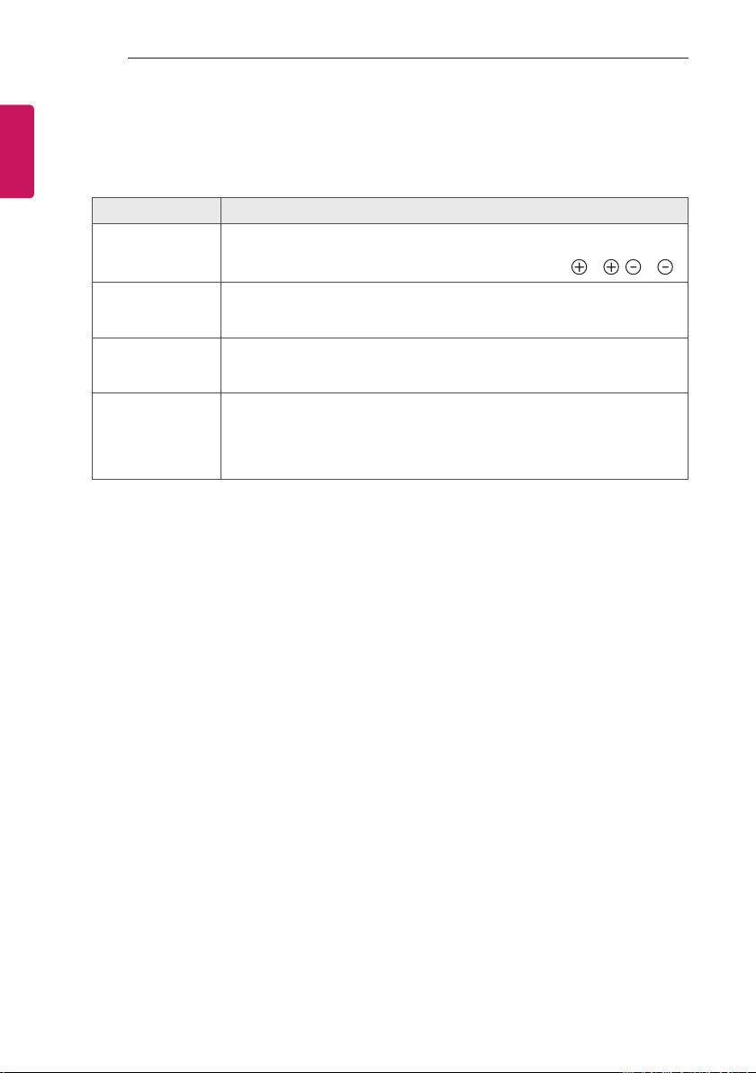
Problem Solution
Cannot control the
TV with the remote
control.
No image display
and no sound is
produced.
The TV turns off
suddenly.
When connecting
to the PC (HDMI),
‘No signal’ or
‘Invalid Format’ is
displayed.
yCheck the remote control sensor on the product and try again.
yCheck if there is any obstacle between the product and the remote control.
yCheck if the batteries are still working and properly installed (
yCheck if the product is turned on.
yCheck if the power cord is connected to a wall outlet.
yCheck if there is a problem in the wall outlet by connecting other products.
yCheck the power control settings. The power supply may be interrupted.
yCheck if the Automatic Standby (Depending on model) / Sleep Timer / Time
Power Off is activated in the TIME settings.
yTurn the TV off/on using the remote control.
yReconnect the HDMI cable.
yRestart the PC with the TV on.
to , to ).
Page 33
SPECIFICATIONS
33
SPECIFICATIONS
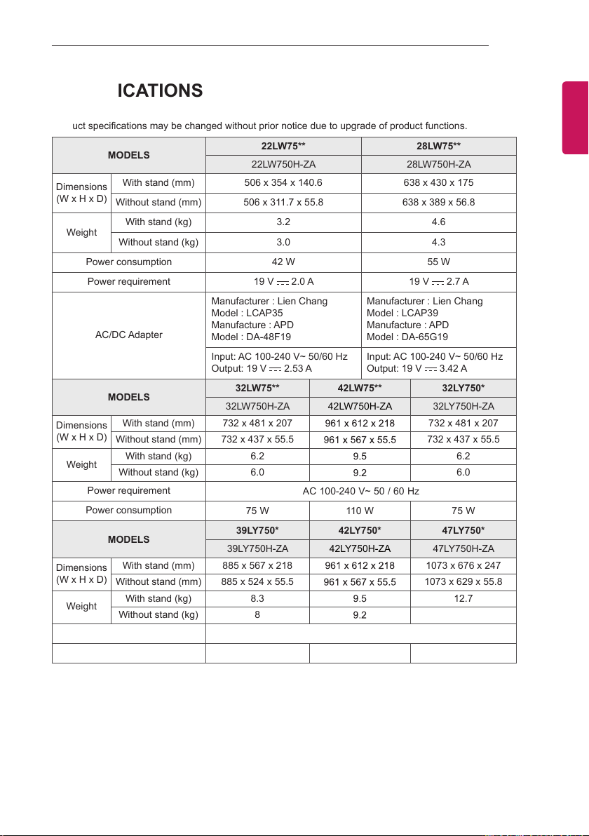
Product specifications may be changed without prior notice due to upgrade of product functions.
MODELS
Dimensions
(W x H x D)
Weight
Dimensions
(W x H x D)
Weight
Dimensions
(W x H x D)
Weight
With stand (mm) 506 x 354 x 140.6 638 x 430 x 175
Without stand (mm) 506 x 311.7 x 55.8 638 x 389 x 56.8
With stand (kg) 3.2 4.6
Without stand (kg) 3.0 4.3
Power consumption 42 W 55 W
Power requirement 19 V
Manufacturer : Lien Chang
Model : LCAP35
AC/DC Adapter
MODELS
With stand (mm) 732 x 481 x 207 961 x 612 x 218 732 x 481 x 207
Without stand (mm) 732 x 437 x 55.5 961 x 567 x 55.5 732 x 437 x 55.5
With stand (kg) 6.2 9.5 6.2
Without stand (kg) 6.0 9.2 6.0
Power requirement
Power consumption
MODELS
With stand (mm) 885 x 567 x 218 961 x 612 x 218 1073 x 676 x 247
Without stand (mm) 885 x 524 x 55.5 961 x 567 x 55.5 1073 x 629 x 55.8
With stand (kg) 8.3 9.5 12.7
Without stand (kg) 8 9.2 12.3
Power requirement
Power consumption
Manufacture : APD
Model : DA-48F19
Input: AC 100-240 V~ 50/60 Hz
Output: 19 V
22LW75** 28LW75**
22LW750H-ZA 28LW750H-ZA
2.0 A 19 V 2.7 A
Manufacturer : Lien Chang
Model : LCAP39
Manufacture : APD
Model : DA-65G19
2.53 A
32LW75** 42LW75** 32LY750*
32LW750H-ZA 42LW750H-ZA 32LY750H-ZA
AC 100-240 V~ 50 / 60 Hz
75 W 110 W 75 W
39LY750* 42LY750* 47LY750*
39LY750H-ZA 42LY750H-ZA 47LY750H-ZA
AC 100-240 V~ 50 / 60 Hz
100 W 110 W 120 W
Input: AC 100-240 V~ 50/60 Hz
Output: 19 V 3.42 A
ENGENGLISH
Page 34
34
SPECIFICATIONS
ENGLISH
ENG
Dimensions
(W x H x D)
Weight
Power requirement
Power consumption
Dimensions
(W x H x D)
Weight
Power requirement
Power consumption
Dimensions
(W x H x D)
Weight
Power requirement
Power consumption
Dimensions
(W x H x D)
Weight
Power requirement
Power consumption
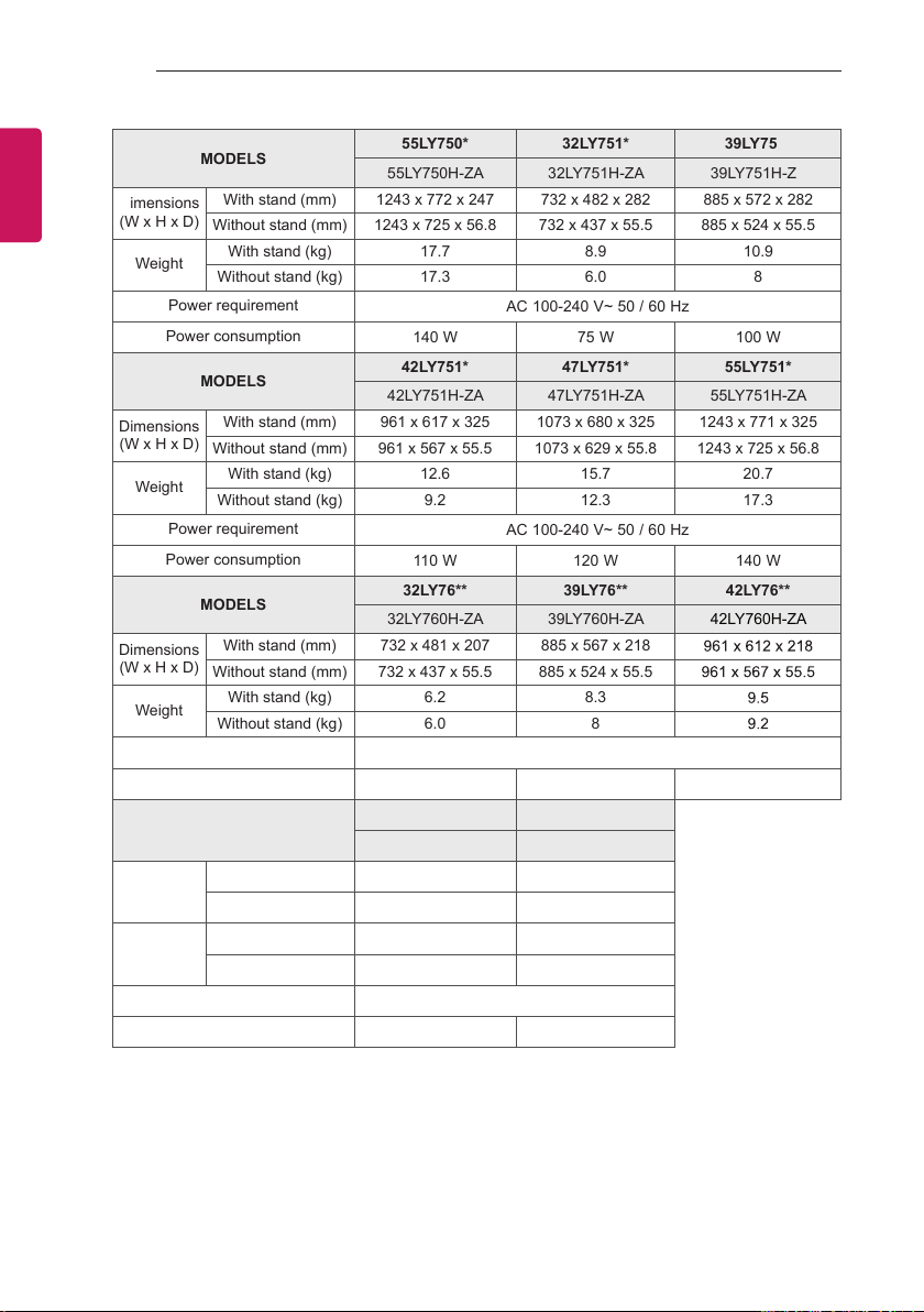
MODELS
With stand (mm) 1243 x 772 x 247 732 x 482 x 282 885 x 572 x 282
Without stand (mm) 1243 x 725 x 56.8 732 x 437 x 55.5 885 x 524 x 55.5
With stand (kg) 17.7 8.9 10.9
Without stand (kg) 17.3 6.0 8
MODELS
With stand (mm) 961 x 617 x 325 1073 x 680 x 325 1243 x 771 x 325
Without stand (mm) 961 x 567 x 55.5 1073 x 629 x 55.8 1243 x 725 x 56.8
With stand (kg) 12.6 15.7 20.7
Without stand (kg) 9.2 12.3 17.3
MODELS
With stand (mm) 732 x 481 x 207 885 x 567 x 218 961 x 612 x 218
Without stand (mm) 732 x 437 x 55.5 885 x 524 x 55.5 961 x 567 x 55.5
With stand (kg) 6.2 8.3 9.5
Without stand (kg) 6.0 8 9.2
MODELS
With stand (mm) 1073 x 676 x 247 1243 x 772 x 247
Without stand (mm) 1073 x 629 x 55.8 1243 x 725 x 56.8
With stand (kg) 12.7 17.7
Without stand (kg) 12.3 17.3
55LY750* 32LY751* 39LY751*
55LY750H-ZA 32LY751H-ZA 39LY751H-ZA
AC 100-240 V~ 50 / 60 Hz
140 W 75 W 100 W
42LY751* 47LY751* 55LY751*
42LY751H-ZA 47LY751H-ZA 55LY751H-ZA
AC 100-240 V~ 50 / 60 Hz
110 W 120 W 140 W
32LY76** 39LY76** 42LY76**
32LY760H-ZA 39LY760H-ZA 42LY760H-ZA
AC 100-240 V~ 50 / 60 Hz
75 W 100 W 110 W
47LY76** 55LY76**
47LY760H-ZA 55LY760H-ZA
AC 100-240 V~ 50 / 60 Hz
120 W 140 W
Page 35
SPECIFICATIONS
35
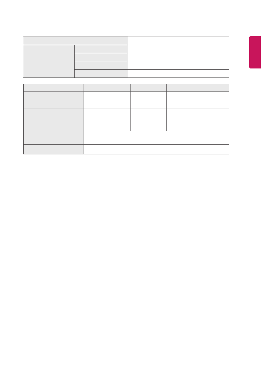
CI Module Size (W x H x D)
100.0 mm x 55.0 mm x 5.0 mm
Operating Temperature 0 °C to 40 °C
Environment condition
Operating Humidity Less than 80 %
Storage Temperature -20 °C to 60 °C
Storage Humidity Less than 85 %
1
Digital TV Analogue TV
DVB-T
DVB-C
VHF, UHF
DVB-S/S2 : 6,000
DVB-T/T2/C & Analogue TV : 1,500
Television system
Programme coverage
Maximum number of
storable programmes
Satellite Digital TV
DVB-T/T2
DVB-C
DVB-S/S2
VHF, UHF
C-Band, Ku-Band
External antenna impedance 75 Ω
1 Satellite and DVB-T2 support models.
ENGENGLISH
PAL/SECAM B/G/D/K,
PAL I/I’,
SECAM L/L’
VHF: E2 to E12,
UHF : E21 to E69,
CATV: S1 to S20,
HYPER: S21 to S47
Page 36
36
0197
0197
SPECIFICATIONS
ENGLISH
ENG
(Only LW75**, LY75**)
Wireless LAN module(TWFM-B006D) specification
Standard IEEE802.11a/b/g/n
Frequency Range
Output Power
(Max.)
yBecause band channel used by the country could be different, the user can not change or adjust
the operating frequency and this product is set for the regional frequency table.
yThis device should be installed and operated with minimum distance 20 cm between the device
and your body. And this phrase is for the general statement for consideration of user environment.
(Only LY76**)
Wireless module(LGSBW41) Specifications
Wireless LAN module
Standard IEEE 802.11a/b/g/n Standard Bluetooth Version 3.0
Frequency
ragne
Output
power(Max.)
yBecause band channel used by the country could be different, the user can not change or adjust
the operating frequency and this product is set for the regional frequency table.
yThis device should be installed and operated with minimum distance 20 cm between the device and
your body. And this phrase is for the general statement for consideration of user environment.
2400 to 2483.5 MHz
5150 to 5250 MHz
5725 to 5850 MHz(for Non EU)
802.11a: 13 dBm
802.11b: 15 dBm
802.11g: 14 dBm
802.11n - 2.4GHz: 16 dBm
802.11n - 5GHz: 16 dBm
2400 to 2483.5 MHz
5150 to 5250 MHz
5725 to 5850 MHz (for Non EU)
802.11a: 11 dBm
802.11b: 14 dBm
802.11g: 10.5 dBm
802.11n - 2.4GHz: 11 dBm
802.11n - 5GHz: 12.5 dBm
Bluetooth
Frequency
ragne
Output
power(Max.)
module
2400 to 2483.5 MHz
10 dBm or Lower
Page 37
SPECIFICATIONS
37
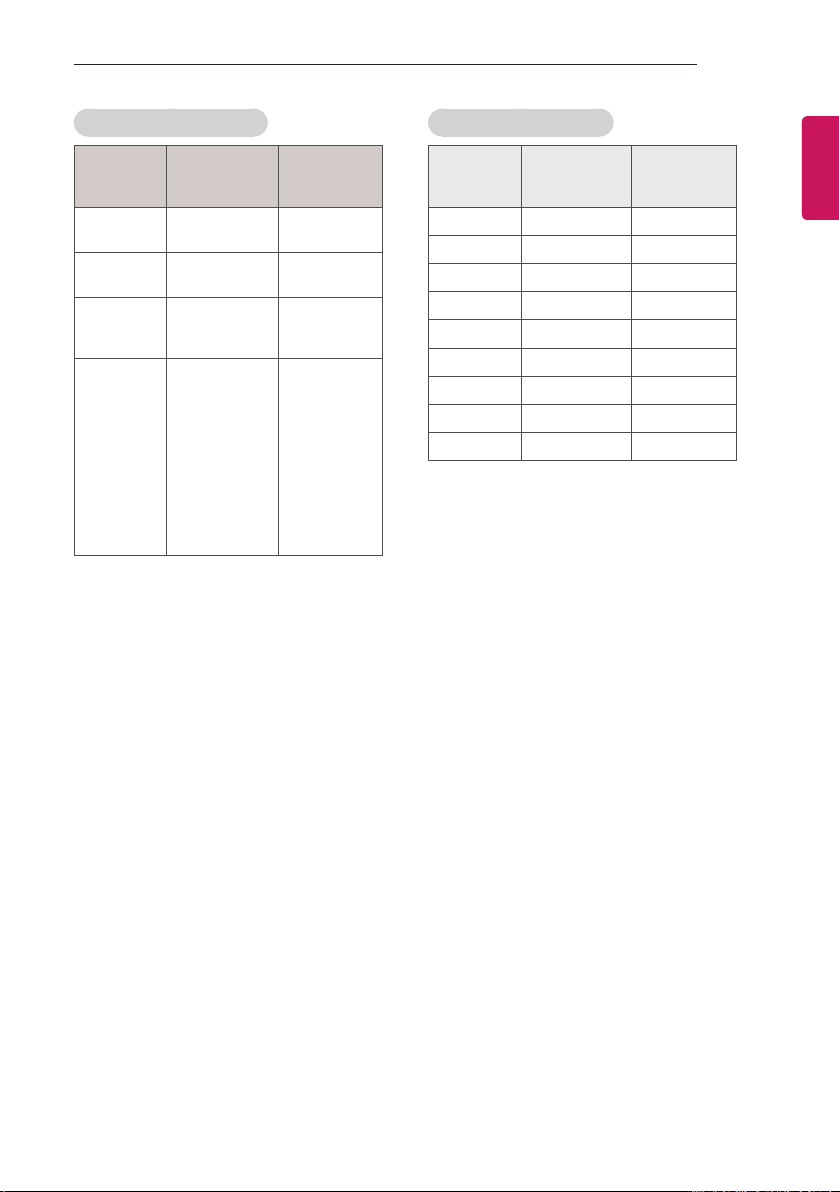
HDMI-DTV Supported Mode
Resolution
720 x 480
720 x 576
1280 x 720
1920 x 1080
Horizontal
Frequency
(kHz)
31.469
31.5
31.25
15.625
37.500
44.96
45
33.72
33.75
28.125
26.97
27
28.125
33.716
33.75
56.250
67.43
67.5
Vertical
Frequency
(Hz)
59.94
60
50
50
50
59.94
60
59.94
60
50.00
23.97
24
25
29.976
30.00
50
59.94
60
HDMI-PC Supported Mode
Resolution
640 x 350 31.468 70.09
720 x 400 31.469 70.08
640 x 480 31.469 59.94
800 x 600 37.879 60.31
1024 x 768 48.363 60.00
1152 x 864 54.348 60.053
1280 x 1024 63.981 60.020
1360 x 768 47.712 60.015
1920 x 1080 67.5 60.00
Horizontal
Frequency
(kHz)
Vertical
Frequency
(Hz)
ENGENGLISH
Page 38
38
IR CODES
ENGLISH
ENG
IR CODES
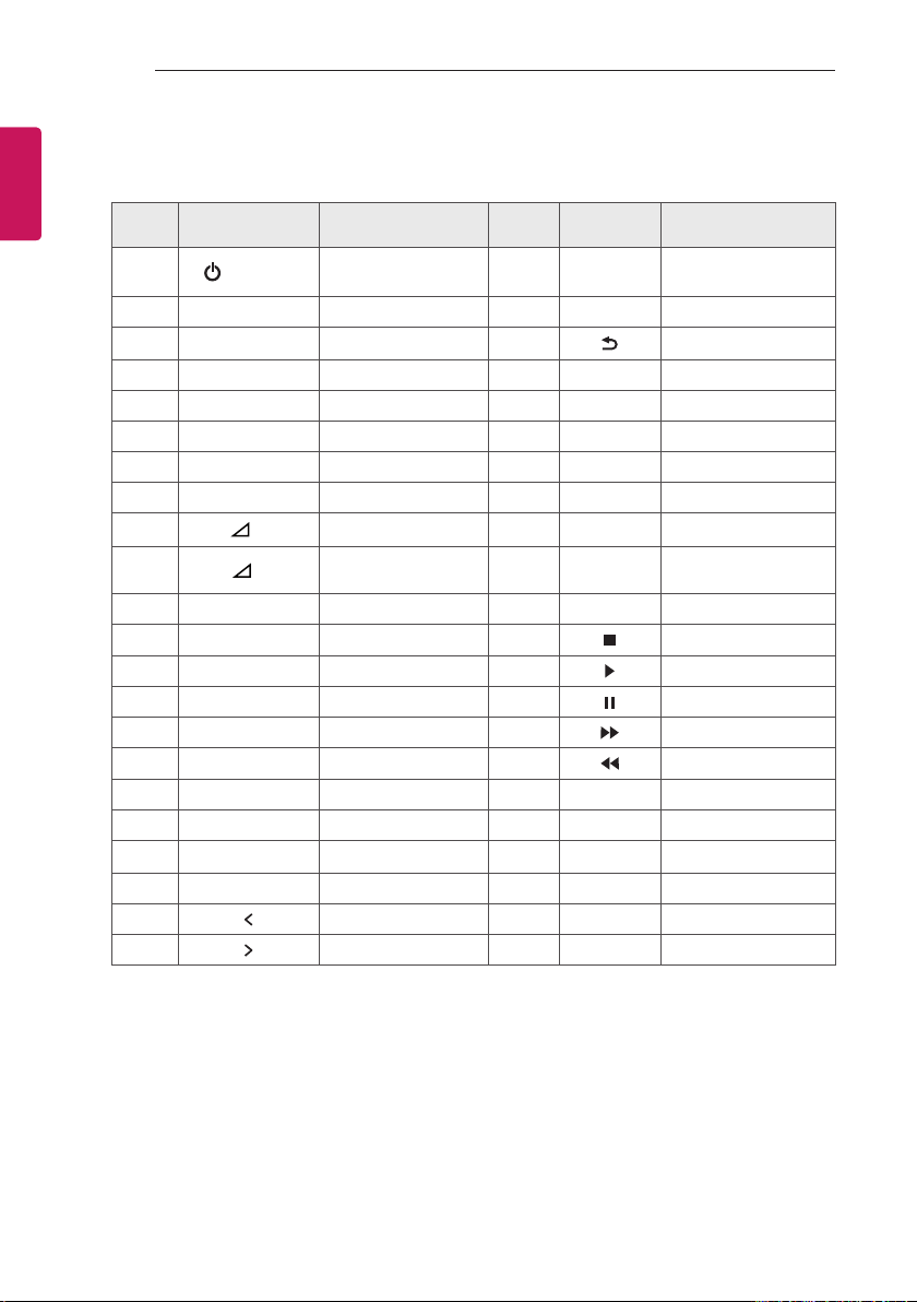
yThis feature is not available for all models.
Code
(Hexa)
08
95 ENERGY SAVING Remote control Button 43 SETTINGS Remote control Button
30 AV MODE Remote control Button 28
0B INPUT Remote control Button 5B EXIT Remote control Button
F0 TV/RAD Remote control Button 72 RED Remote control Button
10-19 Number Key 0-9 Remote control Button 71 GREEN Remote control Button
53 LIST Remote control Button 63 YELLOW Remote control Button
1A Q.VIEW Remote control Button 61 BLUE Remote control Button
02
03
1E FAV Remote control Button
79 RATIO Remote control Button B1
09 MUTE Remote control Button B0
00
01
AB GUIDE Remote control Button 8F
0C PORTAL Remote control Button 7E SIMPLINK Remote control Button
AA INFO Remote control Button 45 Q.MENU Remote control Button
40
41
07
06
Function Note
(POWER)
ꕌ
/ PAGE
P
ꕍ
/
P
+
-
PAGE
ꕌ
ꕍ
Remote control Button
(Power On/Off)
Remote control Button
Remote control Button
Remote control Button BA Remote control Button
ꕌ
Remote control Button 8E Remote control Button
ꕍ
Remote control Button 91 AD Remote control Button
Remote control Button E8 ALARM Remote control Button
Remote control Button 7C SMART Remote control Button
Remote control Button DC 3D Remote control Button
Code
(Hexa)
Function Note
44 OK Remote control Button
Remote control Button
20 TEXT
21
39 SUBTITLE
T.OPT
(T.Option)
Remote control Button
Remote control Button
Remote control Button
Remote control Button
Remote control Button
Remote control Button
Page 39
EXTERNAL CONTROL DEVICE SETUP
RS-232C IN
(CONTROL & SERVICE)
39
EXTERNAL CONTROL DEVICE SETUP
RS-232C Setup
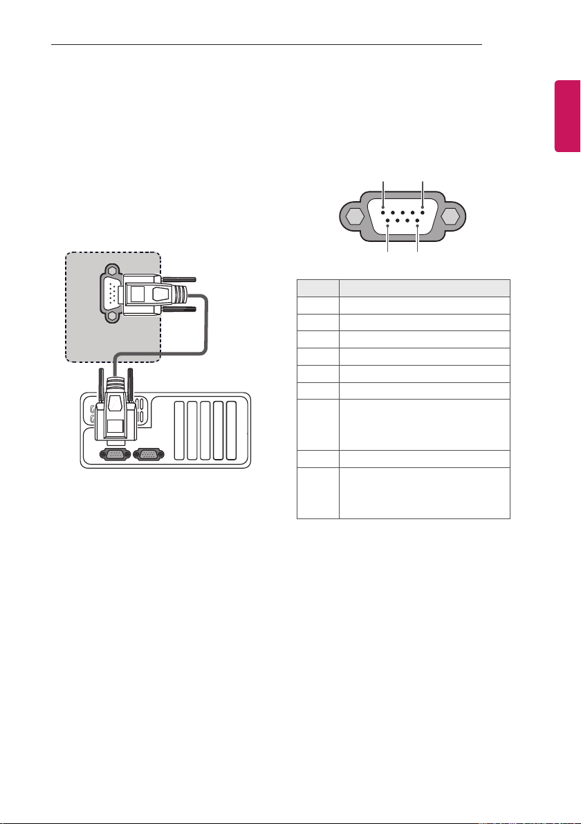
Connect the RS-232C (serial port) input jack to
an external control device (such as a computer
or an A/V control system) to control the product’s
functions externally.
Connect the serial port of the control device to
the RS-232C jack on the product back panel.
* Note : RS-232C connection cables are not
supplied with the product.
(*Not Provided)
Type of Connector: D-Sub 9-Pin Male
No. Pin name
3.5V
1
RXD (Receive data)
2
TXD (Transmit data)
3
IR OUT from TV
4
GND
5
No Connection
6
yNo Connection (Only 22/28LW75**)
yNo Connection (5V available in
7
some models - Only 32/42LW75**,
LY75**, LY76**)
No Connection
8
yNo Connection (Only 22/28LW75**)
yNo Connection (12V available in
9
some models - Only 32/42LW75**,
LY75**, LY76**)
1 5
6
9
ENGENGLISH
Page 40
40
EXTERNAL CONTROL DEVICE SETUP
ENGLISH
ENG
PC TV
2 3
3 2
5 5
4 6
6 4
7 8
8 7
D-Sub 9 D-Sub 9
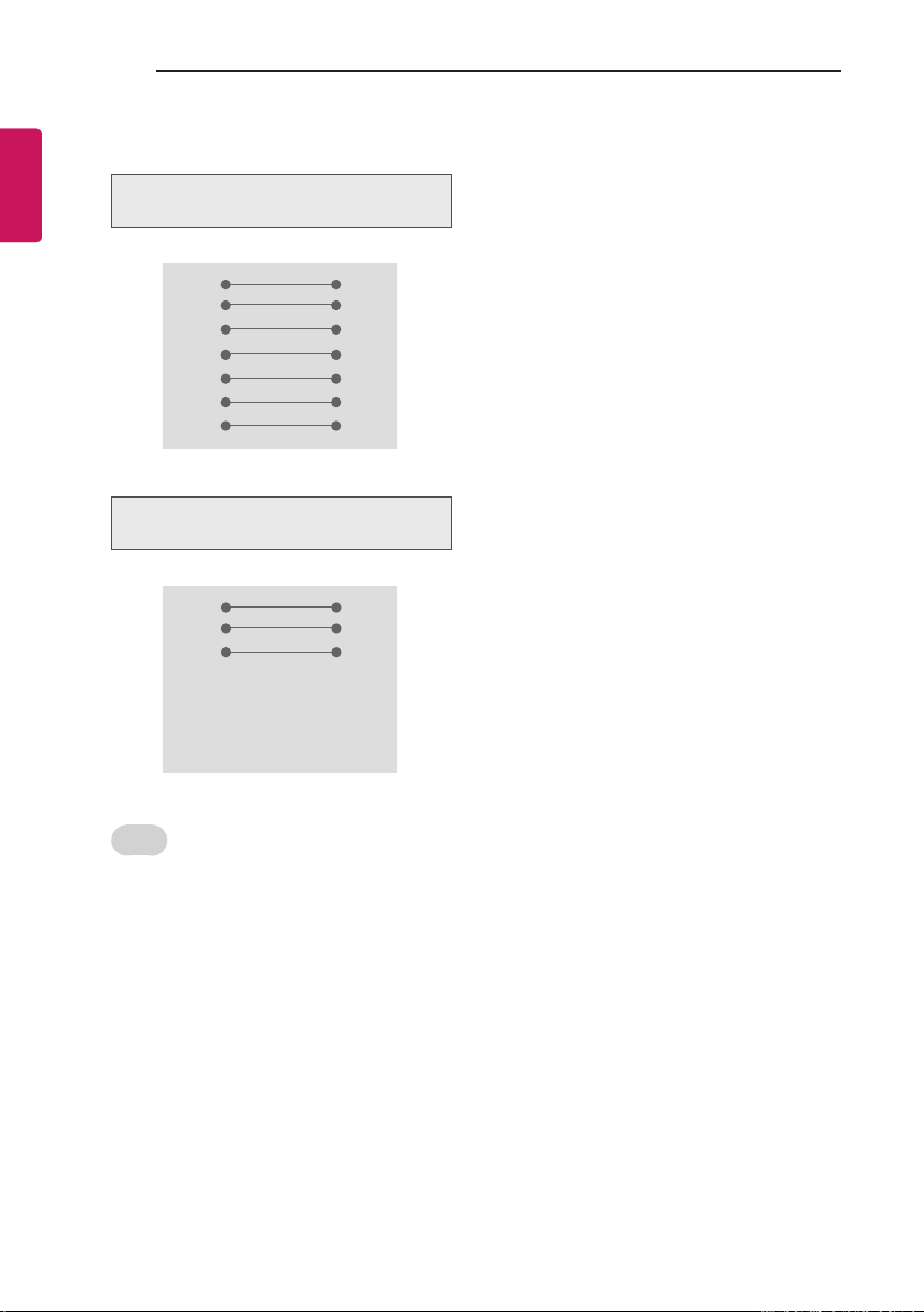
RS-232C Congurations
7-Wire Configurations
(Standard RS-232C cable)
RXD
TXD
GND
DTR
DSR
RTS
CTS
3-Wire Configurations
(Not standard)
PC TV
2 3
RXD
3 2
TXD
5 5
GND
4 6
DTR
6 4
DSR
7 7
RTS
8 8
CTS
D-Sub 9 D-Sub 9
TXD
RXD
GND
DSR
DTR
CTS
RTS
TXD
RXD
GND
DTR
DSR
RTS
CTS
Set ID
Set ID number. “Real Data Mapping”.
1 Press SETTINGS or HOME to access the
main menus.
2 Press the Navigation buttons to scroll to
OPTION and press OK.
3 Press the Navigation buttons to scroll to Set
ID and press OK.
4 Scroll left or right to select a set ID number
and select Close. The adjustment range is
1-99.
5 When you are nished, press EXIT.
Page 41
EXTERNAL CONTROL DEVICE SETUP
41
Communication Parameters
yBaud rate : 9600 bps (UART)
yData length : 8 bits
yParity : None
yStop bit : 1 bit
yCommunication code : ASCII code
yUse a crossed (reverse) cable.
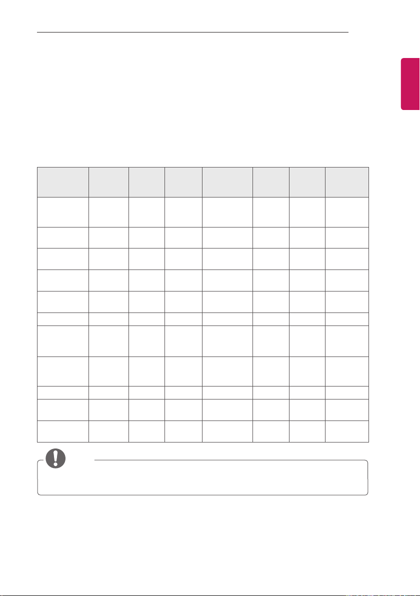
Command Reference List
(Depending on Model)
COM-
MAND1
01. Power k a 00 to 01
02. Aspect
Ratio
03. Screen
Mute
04. Volume
Mute
05. Volume
Control
06. Contrast k g 00 to 64 17. Equalize j v (See p. 45)
07. Brightness k h 00 to 64
COM-
MAND2
k c (See p. 43) 13. Balance k t 00 to 64
k d (See p. 43)
k e 00 to 01
k f 00 to 64
DATA
(Hexa-
decimal)
12. Remote
Control Lock
Mode
14. Colour
Temperature
15. Energy
Saving
16. Auto
Configure
18. Tune
Command
COM-
MAND1
COM-
MAND2
k m 00 to 01
x u 00 to 64
j q 00 to 05
j u 01
m a (See p. 45)
DATA
(Hexadeci-
mal)
ENGENGLISH
08. Colour k i 00 to 64
09. Tint k j 00 to 64 20. Key m c (See p. 46)
10. Sharpness k k 00 to 32
11. OSD
Select
k l 00 to 01
19. Programme Add/
Skip
21. Control
Back Light
22. Input
select
m b 00 to 01
m g 00 to 64
x b (See p. 46)
NOTE
yDuring USB operations such as DivX or EMF, all commands except Power(ka) and Key(mc) are
not executed and treated as NG.
Page 42

42
EXTERNAL CONTROL DEVICE SETUP
ENGLISH
ENG
Transmission / Receiving Protocol
Transmission
[Command1][Command2][ ][Set ID][ ][Data][Cr]
[Command 1] : First command to control the TV.(j, k, m or x)
[Command 2] : Second command to control the TV.
[Set ID] : You can adjust the set ID to choose desired monitor ID number in option menu.
Adjustment range is 1 to 99. When selecting Set ID ‘0’, every connected set is controlled.
Set ID is indicated as decimal (1 to 99) on menu and as Hexa decimal (0x0 to 0x63)
on transmission/receiving protocol.
[DATA] : To transmit command data. Transmit ‘FF’ data to read status of command.
[Cr] : Carriage Return
ASCII code ‘0x0D’
[ ] : ASCII code ‘space (0x20)’
OK Acknowledgement
[Command2][ ][Set ID][ ][OK][Data][x]
* The set transmits ACK (acknowledgement) based on this format when receiving normal data. At this
time, if the data is data read mode, it indicates present status data. If the data is data write mode, it
returns the data of the PC computer.
Error Acknowledgement
[Command2][ ][Set ID][ ][NG][Data][x]
* The set transmits ACK (acknowledgement) based on this format when receiving abnormal data from
non-viable functions or communication errors.
Data 00 : Illegal Code
Page 43

EXTERNAL CONTROL DEVICE SETUP
43
01. Power (Command: k a)
► To control Power On/Off of the set.
Transmission[k][a][ ][Set ID][ ][Data][Cr]
Data 00 : Power Off 01 : Power On
Ack [a][ ][Set ID][ ][OK/NG][Data][x]
► To Show TV is Power On/Off.
Transmission [k][a][ ][Set ID][ ][FF][Cr]
Ack [a][ ][Set ID][ ][OK/NG][Data][x]
* Similarly, if other functions transmit ‘0xFF’ data
based on this format, Acknowledgement data
feed back presents status about each function.
* OK Ack., Error Ack. and other message may
display on the screen when TV is power On.
02. Aspect Ratio (Command: k c)
(Main Picture Size)
► To adjust the screen format. (Main picture
format) You can also adjust the screen format
using the Aspect Ratio n the Q.MENU. or
PICTURE menu.
Transmission [k][c][ ][Set ID][ ][Data][Cr]
Data 01 : Normal screen
(4:3)
02 : Wide screen
(16:9)
04 : Zoom
06 : Original
Ack [c][ ][Set ID][ ][OK/NG][Data][x]
* Using the PC input, you select either 16:9 or
4:3 screen aspect ratio.
* In DTV/HDMI (1080i 50 Hz / 60 Hz, 720p 50Hz
/ 60 Hz, 1080p 24 Hz / 30 Hz / 50 Hz / 60 Hz),
Component (720p, 1080i, 1080p 50 Hz / 60 Hz)
mode, Just Scan is available.
* Full Wide is supported only for Digital,
Analogue, AV.
07 : 14:9
09 : Just Scan
0B : Full Wide
10 to 1F : Cinema
Zoom 1 to 16
03. Screen Mute (Command: k d)
► To select screen mute on/off.
Transmission [k][d][ ][Set ID][ ][Data][Cr]
Data 00 : Screen mute off (Picture on)
Video mute off
01 : Screen mute on (Picture off)
10 : Video mute on
Ack [d][ ][Set ID][ ][OK/NG][Data][x]
* In case of video mute on only, TV will display
On Screen Display(OSD). But, in case of
Screen mute on, TV will not display OSD.
04. Volume Mute (Command: k e)
► To control volume mute on/off.
You can also adjust mute using the MUTE
button on remote control.
Transmission [k][e][ ][Set ID][ ][Data][Cr]
Data 00 : Volume mute on (Volume off)
01 : Volume mute off (Volume on)
Ack [e][ ][Set ID][ ][OK/NG][Data][x]
05. Volume Control (Command: k f)
► To adjust volume.
You can also adjust volume with the volume
buttons on remote control.
Transmission [k][f][ ][Set ID][ ][Data][Cr]
Data Min : 00 to Max : 64
* Refer to ‘Real data mapping’. See p. 46.
Ack [f][ ][Set ID][ ][OK/NG][Data][x]
06. Contrast (Command: k g)
► To adjust screen contrast.
You can also adjust contrast in the PICTURE
menu.
Transmission [k][g][ ][Set ID][ ][Data][Cr]
Data Min : 00 to Max : 64
* Refer to ‘Real data mapping’. See p. 46.
Ack [g][ ][Set ID][ ][OK/NG][Data][x]
ENGENGLISH
Page 44

44
EXTERNAL CONTROL DEVICE SETUP
ENGLISH
ENG
07. Brightness (Command: k h)
► To adjust screen brightness.
You can also adjust brightness in the
PICTURE menu.
Transmission [k][h][ ][Set ID][ ][Data][Cr]
Data Min : 00 to Max : 64
* Refer to ‘Real data mapping’. See p. 46.
Ack [h][ ][Set ID][ ][OK/NG][Data][x]
08. Colour (Command: k i)
► To adjust the screen Colour.
You can also adjust colour in the PICTURE
menu.
Transmission [k][i][ ][Set ID][ ][Data][Cr]
Data Min : 00 to Max : 64
* Refer to ‘Real data mapping’. See p. 46.
Ack [i][ ][Set ID][ ][OK/NG][Data][x]
09. Tint (Command: k j)
► To adjust the screen tint.
You can also adjust tint in the PICTURE
menu.
Transmission [k][j][ ][Set ID][ ][Data][Cr]
Data Red : 00 to Green : 64
* Refer to ‘Real data mapping’. See p. 46.
Ack [j][ ][Set ID][ ][OK/NG][Data][x]
10. Sharpness (Command: k k)
► To adjust the screen sharpness.
You can also adjust sharpness in the
PICTURE menu.
Transmission [k][k][ ][Set ID][ ][Data][Cr]
Data Min : 00 to Max : 32
* Refer to ‘Real data mapping’. See p. 46.
Ack [k][ ][Set ID][ ][OK/NG][Data][x]
11. OSD Select (Command: k l)
► To select OSD (On Screen Display) on/off
when controlling remotely.
Transmission [k][l][ ][Set ID][ ][Data][Cr]
Data 00 : OSD off 01 : OSD on
Ack [l][ ][Set ID][ ][OK/NG][Data][x]
12. Remote control lock mode (Command: k m)
► To lock the front panel controls on the monitor
and remote control.
Transmission [k][m][ ][Set ID][ ][Data][Cr]
Data 00 : Lock off 01 : Lock on
Ack [m][ ][Set ID][ ][OK/NG][Data][x]
* If you are not using the remote control, use
this mode. When main power is on/off, external
control lock is released.
* In the standby mode, if key lock is on, TV will
not turn on by power on key of IR & Local Key.
13. Balance (Command: k t)
► To adjust balance.
You can also adjust balance in the AUDIO
menu.
Transmission [k][t][ ][Set ID][ ][Data][Cr]
Data Min : 00 to Max : 64
* Refer to ‘Real data mapping’. See p. 46.
Ack [t][ ][Set ID][ ][OK/NG][Data][x]
14. Colour Temperature (Command: x u)
► To adjust colour temperature. You can also
adjust Colour Temperature in the PICTURE
menu.
Transmission [x][u][ ][Set ID][ ][Data][Cr]
Data Min : 00 to Max : 64
* Refer to ‘Real data mapping’. See p. 46.
Ack [u][ ][Set ID][ ][OK/NG][Data][x]
Page 45
EXTERNAL CONTROL DEVICE SETUP
45
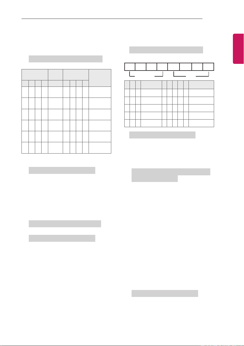
15. Energy Saving (Command: j q)
► To reduce the power consumption of the
TV. You can also adjust Energy Saving in
PICTURE menu.
Transmission [j][q][ ][Set ID][ ][Data][Cr]
Power Saving
Function
7 6 5 4 3 2 1 0
0 0 0 0
0 0 0 0
0 0 0 0
0 0 0 0
0 0 0 0
0 0 0 0
► 'Auto' is available in TV that supports
'Intelligent Sensor'.
Ack [q][ ][Set ID][ ][OK/NG][Data][x]
16. Auto Configure (Command: j u)
(Only RGB support model)
► To adjust picture position and minimize image
shaking automatically. It works only in RGB
(PC) mode.
Transmission [j][u][ ][Set ID][ ][Data][Cr]
Data 01 : To set
Ack [u][ ][Set ID][ ][OK/NG][Data][x]
Low
Power
Low
Power
Low
Power
Low
Power
Low
Power
Low
Power
Level
0 0 0 0 Off
0 0 0 1 Minimum
0 0 1 0 Medium
0 0 1 1 Maximum
0 1 0 1 Screen Off
0 1 0 0 Auto
Description
17. Equalizer (Command : j v)
► To adjust equalize.
Transmission [j][v][ ][Set ID][ ][Data][Cr]
MSB LSB
0 0 0 0 0 0 0 0
Frequency
7 6 5
Frequency
0 0 0 1st Band 0 0 0 0 0 0(decimal)
0 0 1 2nd Band 0 0 0 0 1 1(decimal)
0 1 0 3rd Band ... ... ... ... ... ...
0 1 1 4th Band 0 0 0 1 1 19(decimal)
1 0 0 5th Band 0 0 1 0 1 20(decimal)
Ack [v][ ][Set ID][ ][OK/NG][Data][x]
18. Tune Command (Command: m a)
► Select channel to following physical number.
Transmission [m][a][ ][Set ID][ ][Data 00][ ]
[Data 01][ ][Data 02][Cr]
Data 00 : High channel data
Data 01 : Low channel data
ex. No. 47 -> 00 2F (2FH)
No. 394 -> 01 8A (18AH),
DTV No. 0 -> Don’t care
Data 02 : [Antenna]
0x00 : Analog Main
0x10 : DTV Main
0x20 : Radio
[Cable]
0x80 : Analog Main
0x90 : DTV Main
0xA0 : Radio
[Satellite - Only LY76**]
0x40 : DTV Main
0x50 : Radio Main
Channel data range
Analogue - Min: 00 to Max: 63 (0 to 99)
Digital - Min: 00 to Max: 3E7 (0 to 999)
Ack [a][ ][Set ID][ ][OK/NG][Data][x]
4 3 2 1 0 Step
Data
ENGENGLISH
Data Min: 00 to Max: 7DH
Page 46
46
EXTERNAL CONTROL DEVICE SETUP
ENGLISH
ENG
19. Programme Add/Skip (Command: m b)
► To set skip status for the current Programme.
Transmission [m][b][ ][Set ID][ ][Data][Cr]
Data 00 : Skip 01 : Add
Ack [b][ ][Set ID][ ][OK/NG][Data][x]
20. Key (Command: m c)
► To send IR remote key code.
Transmission [m][c][ ][Set ID][ ][Data][Cr]
Data Key code - See p. 38.
Ack [c][ ][Set ID][ ][OK/NG][Data][x]
21. Control Backlight (Command: m g)
► To control the backlight.
Transmission [m][g][ ][Set ID][ ][Data][Cr]
Data Min : 00 to Max : 64
Ack [g][ ][Set ID][ ][OK/NG][Data][x]
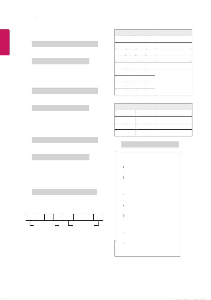
22. Input select (Command: x b)
(Main Picture Input)
► To select input source for main picture.
Transmission [x][b][ ][Set ID][ ][Data][Cr]
Data Structure
MSB LSB
0 0 0 0 0 0 0 0
External Input Input Number
External Input Data
0 0 0 0 DTV
0 0 0 1 Analogue
0 0 1 0 AV
0 1 0 0 Component
0 1 1 0 RGB
0 1 1 1
1 0 0 0
1 0 0 1
1 0 1 0
Input Number Data
0 0 0 0 Input1
0 0 0 1 Input2
0 0 1 0 Input3
0 0 1 1 Input4
Ack [b][ ][Set ID][ ][OK/NG][Data][x]
* Real data mapping
00 : Step 0
A : Step 10 (Set ID 10)
F : Step 15 (Set ID 15)
10 : Step 16 (Set ID 16)
64 : Step 100
6E : Step 110
73 : Step 115
74 : Step 116
HDMI
CF : Step 199
FE : Step 254
FF : Step 255
Page 47
Record the model number and serial number of
the TV.
Refer to the label on the back cover and quote
this information to your dealer when requiring
any service.
MODEL
SERIAL
 Loading...