

Page 1

OWNER’S MANUAL
LCD TV
Please read this manual carefully before operating
your set and retain it for future reference.
www.lg.com
Page 2

HDMI, the HDMI logo and High-Definition
Multimedia Interface are trademarks or registered
trademarks of HDMI Licensing LLC.
Page 3

1
ACCESSORIES
ACCESSORIES
Bolts for stand assembly
(Refer to p. 11)
x 4
Protection cover
(Refer to p. 12)
Ensure that the following accessories are included with your TV.
If an accessory is missing, please contact the dealer where you purchased the TV.
■
Image shown may differ from your TV.
Owner’s Manual
Batteries (AAA)
Power Cord
Polishing Cloth
Polishing cloth for use on the screen.
This item is not included for all models.
* Lightly wipe any stains or fingerprints on
the surface of the TV with the polishing
cloth.
Do not use excessive force. This may cause
scratching or discolouration.
Remote Control
OOnnllyy 2222LLKK33****
Protection cover
(Refer to p. 12)
Cable Holder
(Refer to p. 13)
Bolts for stand
assembly
(Refer to p. 10)
OOnnllyy 2266//3322LLKK33****,, 3322//4422LLKK44****
Protection cover
(Refer to p. 12)
x 8
M4 x 20
1-screw for
stand fixing
(Refer to p. 11)
Wall Mounting Bracket(Separate purchase)
OOnnllyy 1199//2222//2266//3322LLVV22******
LSW100B or
LSW100BG
(22/26/32LK3**, 32LK4**)
or
LSW200B or
LSW200BG
(42LK4**)
Home
Page 4

CONTENTS
2
CONTENTS
ACCESSORIES
. . . . . . . . . . . . . . . . . . . . . . . . . . . . . . . . . . . . . . . . . . . .
1
PREPARATION
Front Panel Controls..................................................... 4
Back Panel Information ................................................ 6
Stand Installation......................................................... 10
Swivel Stand ................................................................. 11
Attaching the TV to a desk .........................................11
Positioning your Display ........................................... 11
Not Using the desk-type stand.................................12
Back Cover for Wire Arrangement........................... 13
Careful Installation Advice......................................... 14
Desktop Pedestal Installation................................... 14
Wall Mount: Horizontal Installation........................ 15
Kensington Security System .................................... 15
Antenna Connection................................................... 16
EXTERNAL EQUIPMENT SETUP
HD Receiver Setup...................................................... 17
DVD Setup .....................................................................20
VCR Setup......................................................................22
USB in Setup ............................................................... 23
Other A/V Source Setup........................................... 24
External Stereo Setup ................................................ 25
AV Output Setup ........................................................ 26
PC Setup........................................................................ 26
- Screen Setup for PC Mode .............................. 28
WATCHING TV / PROGRAMME CONTROL
Remote Control Key Functions................................ 32
Turning on the TV....................................................... 36
Programme Selection ................................................ 36
Volume Adjustment .....................................................36
Quick Menu ................................................................. 37
On-Screen Menus Selection and Adjustment..... 38
Auto Programme Tuning............................................ 39
Manual Programme Tuning ....................................... 40
Programme Edit............................................................ 42
Selecting the Programme List ...................................44
Favourite Programme Setup...................................... 45
Input List........................................................................ 46
Input Label .................................................................... 47
..................................................................48
Key Lock......................................................................... 50
Initializing(Reset to original factory settings)...... 51
AV Mode........................................................................ 52
TO USE A USB DEVICE
When connecting the USB device.......................... 53
Photo List ...................................................................... 55
Music List........................................................................59
Movie List........................................................................62
DivX Registration Code..............................................66
Deactivation...................................................................67
PICTURE CONTROL
Picture Size (Aspect Ratio) Control ...................... 68
Energy Saving............................................................... 70
Preset Picture Settings
- Picture Mode-Preset............................................ 71
Manual Picture Adjustment
- Picture Mode-User option................................. 72
Picture Improvement Technology........................... 73
Expert Picture Control ................................................74
Picture Reset................................................................. 77
Power Indicator..............................................................78
Demo Mode.................................................................. 79
Mode Setting................................................................ 80
Page 5

CONTENTS
3
SOUND & LANGUAGE CONTROL
Auto Volume Leveler................................................... 81
Preset Sound Settings - Sound Mode................... 82
Sound Setting Adjustment - User Mode ...............83
Infinite Surround.......................................................... 84
Clear Voice ll................................................................. 85
Balance........................................................................... 86
TV Speakers On/ Off Setup..................................... 87
Audio Reset....................................................................88
I/II
- Stereo/Dual Reception....................................... 89
- NICAM Reception.............................................................. 90
- Speaker Sound Output Selection.................... 90
On-Screen Menu Language Selection ......................... 91
TIME SETTING
Clock Setup .................................................................. 92
Auto On/ Off Timer Setting..................................... 93
Sleep Timer Setting .................................................... 93
TELETEXT
Switch on/off ............................................................... 94
SIMPLE Text.................................................................. 94
TOP Text........................................................................ 94
FASTEXT........................................................................ 95
Special Teletext Functions......................................... 95
APPENDIX
Troubleshooting........................................................... 96
Maintenance ................................................................ 98
Product Specifications............................................... 99
IR Codes ...................................................................... 101
External Control Device Setup...............................102
Page 6

4
PREPARATION
PREPARATION
FRONT PANEL CONTROLS
■
Image shown may differ from your TV.
INPUT
HOME
OK
P
P
OK
HOME
INPUT
PROGRAMME
VOLUME
OK
HOME
POWER
INPUT
Only 26/32LK3**
PROGRAMME
VOLUME
OK
HOME
INPUT
POWER
Only 22LK3**
Remote Control Sensor
Power/Standby Indicator
•
Can be adjusted using the Power Indicator in the
OPTION menu.
G
Do not step on the glass stand or subject it to any impact.
It may break, causing possible injury from fragments of glass, or the TV may fall.
G
Do not drag the TV. The floor or the product may be damaged.
CAUTION
NOTE
!
G
The energy consumed during use can be significantly reduced if the level of brightness of the picture is
reduced, and this will reduce the overall running cost.
SPEAKER
Page 7

5
PREPARATION
PROGRAMME
VOLUME
OK
HOME
INPUT
POWER
Remote Control Sensor
■
Image shown may differ from your TV.
Only 32/42LK4
**
SPEAKER
Power/Standby Indicator
•
Can be adjusted using the Power Indicator
in the OPTION menu.
P
OK
HOME
INPUT
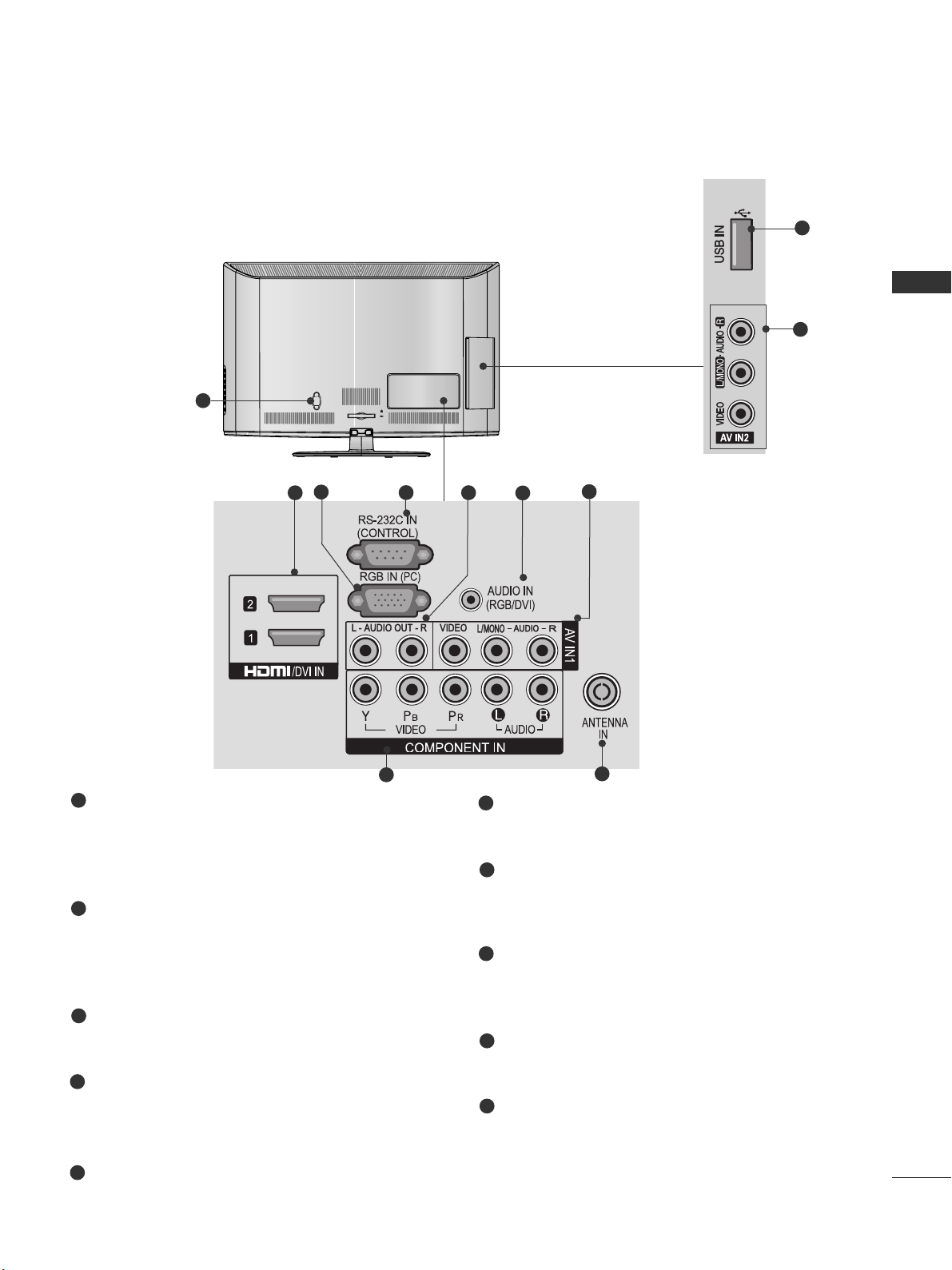
Page 8

Power Cord Socket
This TV operates on an AC power. The voltage is
indicated on the Specifications page. Never
attempt to operate the TV on DC power.
HDMI Input
Connect a HDMI signal to HDMI IN.
Or DVI(VIDEO)signal to HDMI/DVI port with DVI
to HDMI cable.
RGB IN Input
Connect the output from a PC.
RS-232C IN PORT
Connect to the RS-232C port on a PC.
This port is used for Service or Hotel mode.
Audio output
Connect an external amplifier or add a subwoofer
to your surround sound system.
RGB/DVI Audio Input
Connect the audio from a PC.
Audio/Video Input
Connect audio/video output from an external
device to these jacks.
Component Input
Connect a component video/audio device to
these jacks.
Antenna Input
Connect RF antenna to this jack.
USB IN Input
Connect USB storage device to this jack.
6
PREPARATION
PREPARATION
BACK PANEL INFORMATION
■
Image shown may differ from your TV.
K
AC-IN
1
Only
22LK3**
2
8
9
3
6
7
4
10
1
2
3
4
5
6
7
8
9
10
5
Page 9
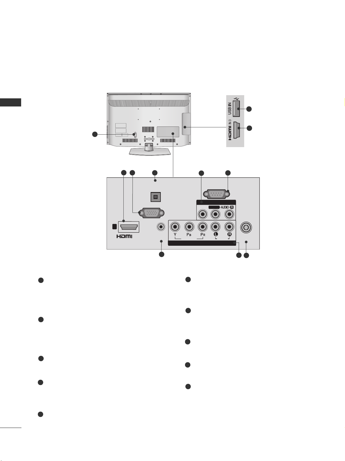
Power Cord Socket
This TV operates on an AC power. The voltage is
indicated on the Specifications page. Never
attempt to operate the TV on DC power.
HDMI Input
Connect a HDMI signal to HDMI IN.
Or DVI(VIDEO)signal to HDMI/DVI port with DVI
to HDMI cable.
RGB IN Input
Connect the output from a PC.
RS-232C IN PORT
Connect to the RS-232C port on a PC.
This port is used for Service or Hotel mode.
Audio output
Connect an external amplifier or add a subwoofer
to your surround sound system.
RGB/DVI Audio Input
Connect the audio from a PC.
Audio/Video Input
Connect audio/video output from an external
device to these jacks.
Component Input
Connect a component video/audio device to
these jacks.
Antenna Input
Connect RF antenna to this jack.
USB IN Input
Connect USB storage device to this jack.
7
PREPARATION
■
Image shown may differ from your TV.
AC IN
CABLE MANAGEMENT
1
2
8
9
3
6
7
4
7
10
Only
26/32LK3**
5
1
2
3
4
5
6
7
8
9
10
Page 10
RGB IN
(PC)
RS-232C IN
(CONTROL & SERVICE)
AUDIO IN
(RGB/DVI)
ANTENNA /
CABLE IN
/DVI IN
OPTICAL
DIGITAL
AUDIO OUT
VIDEOVIDEO
AUDIO
VIDEO
COMPONENT IN
AV IN 1
1
L/MONOL/MONO
R
AUDIO
HDMI IN 3 USB IN
H/P
8
PREPARATION
PREPARATION
■
Image shown may differ from your TV.
1
Only
32/42LK4**
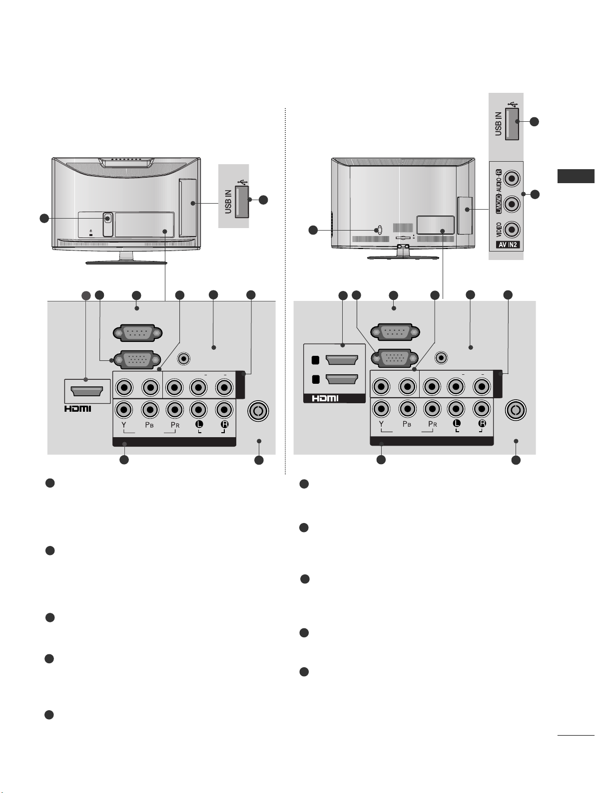
Power Cord Socket
This TV operates on an AC power. The voltage is
indicated on the Specifications page. Never
attempt to operate the TV on DC power.
HDMI Input
Connect a HDMI signal to HDMI IN.
Or DVI(VIDEO)signal to HDMI/DVI port with DVI
to HDMI cable.
RGB IN Input
Connect the output from a PC.
RS-232C IN PORT
Connect to the RS-232C port on a PC.
This port is used for Service or Hotel mode.
RGB/DVI Audio Input
Connect the audio from a PC.
Audio/Video Input
Connect audio/video output from an external
device to these jacks.
Component Input
Connect a component video/audio device to
these jacks.
Antenna Input
Connect RF antenna to this jack.
USB IN Input
Connect USB storage device to this jack.
OPTICAL DIGITAL AUDIO OUT
Connect digital audio to various types of equipment.
Connect to a Digital Audio Component.
Use an Optical audio cable..
1
2
3
4
5
7
6
8
9
2
9
10
2
8
3
6
7
10
4
5
Page 11
9
PREPARATION
K
AC-IN
1
COMPONENT IN
AUDIO
VIDEO
ANTENNA
IN
L(L(MONO)MONO)
R
AUDIOAUDIO
VIDEOVIDEOL - AUDIO OUT - RL - AUDIO OUT - R
AV IN
AUDIO IN
(RGB/DVI)
RGB IN
(PC)
RS-232C IN
(CONTROL)
/DVI IN
2
8
9
3
6
7
4
10
Only
19/22LV2***
■
Image shown may differ from your TV.
AC IN
CABLE MANAGEMENT
1
MONO
AUDIO
VIDEO
L - AUDIO OUT - R
ANTENNA
IN
L( MONO)
R
AUDIO
VIDEOL - AUDIO OUT - R
2
8
9
3
6
7
4
7
10
Only
26/32LV2***
Power Cord Socket
This TV operates on an AC power. The voltage is
indicated on the Specifications page. Never
attempt to operate the TV on DC power.
HDMI Input
Connect a HDMI signal to HDMI IN.
Or DVI(VIDEO)signal to HDMI/DVI port with DVI
to HDMI cable.
RGB IN Input
Connect the output from a PC.
RS-232C IN PORT
Connect to the RS-232C port on a PC.
This port is used for Service or Hotel mode.
Audio output
Connect an external amplifier or add a subwoofer
to your surround sound system.
RGB/DVI Audio Input
Connect the audio from a PC.
Audio/Video Input
Connect audio/video output from an external
device to these jacks.
Component Input
Connect a component video/audio device to
these jacks.
Antenna Input
Connect RF antenna to this jack.
USB IN Input
Connect USB storage device to this jack.
1
2
3
4
6
8
7
9
10
5
5
5
AUDIO IN
(RGB/DVI)
AUDIO
L/L/MONO
R
AV IN1
2
1
RS-232C IN
(CONTROL)
RGB IN
(PC)
L - AUDIO OUT - R
VIDEO
/DVI IN
VIDEO
AUDIO
COMPONENT IN
ANTENNA
IN
Page 12

10
PREPARATION
PREPARATION
STAND INSTALLATION
■
Image shown may differ from your TV.
■
When assembling the desk type stand, check whether the bolt is fully tightened. (If not tightened fully, the
product can tilt forward after the product installation.) If you tighten the bolt with excessive force, the bolt can
deviate from abrasion of the tightening part of the bolt.
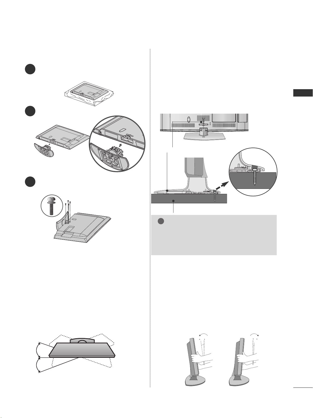
1
Carefully place the TV screen side down on a cushioned surface to protect the screen from damage.
2
Assemble the TV as shown.
Only 22LK3**
1
3
4
Carefully place the TV screen side down on a
cushioned surface to protect the screen from
damage.
2
Assemble the parts of the
SSttaanndd BBoo ddyy
with
the
SSttaanndd BBaassee
of the TV.
Assemble the TV as shown.
Fix the 4 bolts securely using the holes in the
back of the TV.
Stand Body
Stand Base
Only 26/32LK3**, 32/42LK4**
M4X20
M4X20
Page 13
11
PREPARATION
1
2
3
Carefully place the TV screen side down on a cushioned
surface to protect the screen from damage.
Assemble the TV as shown.
Fix the 4 bolts securely using the holes in the
back of the TV.
Only 19/22/26/LV2***
Only 26/32LK3**, 32/42LK4**
ATTACHING THE TV TO A DESK
■
Image shown may differ from your TV.
The TV must be attached to desk so it cannot be pulled
in a forward/backward direction, potentially causing
injury or damaging the product. Use only an attached
screw.
AC IN
CABLE MANAGEMENT
1-Screw (provided as parts of the product)
Desk
Stand
WARNING
!
G
To prevent TV from falling over, the TV should
be securely attached to the floor/wall per installation instructions. Tipping, shaking, or rocking the
machine may cause injury.
SWIVEL STAND
(Except 22LK3**)
■
This feature is not available for all models.
■
After installing the TV, you can adjust the TV manually
to the left or right direction by 20 degrees to suit your
viewing position.
POSITIONING YOUR DISPLAY
(Only 22LK3**)
■
Image shown may differ from your TV.
■
Adjust the position of the panel in various ways for
maximum comfort.
• Tilt range
12
0
3
0
Page 14

12
PREPARATION
PREPARATION
Insert the
PPrroo tteeccttiioonn CCoovveerr
into the TV until
clicking sound.
■
Image shown may differ from your TV.
When installing the wall-mounted unit, use the protection cover.
NOT USING THE DESK-TYPE STAND
Loose the bolts from TV.
After removing the protection paper from the
protection cover, adhere it to the TV as shown.
Detach the
SS ttaanndd
from
TTVV
.
2
3
4
Only 22LK3**
1
Carefully place the TV screen side down on a cushioned surface to protect the screen from damage.
Protection Cover
Insert the
PPrroo tteeccttiioonn CCoovveerr
into the TV until clicking
sound.
PPrroo tteecc ttiioonn CCoovv eerr
Only 26/32LK3**, 32/42LK4**
Only 19/22/26/32LV2***
PPrroo tteecc ttiioonn CCoovv eerr
Page 15

13
PREPARATION
BACK COVER FOR WIRE ARRANGEMENT
■
Image shown may differ from your TV.
Only 22LK3**
After Connecting the cables as necessary, install
CABLE HOLDER as shown and bundle the cables.
K
AC-IN
K
AC-IN
AC IN
AC IN
AC IN
Connect the cables as necessary.
To connect additional equipment, see the External
Equipment Setup section of the manual.
1
Open the
CCaabbllee MMaannaaggeemmeenntt CCllii pp
as shown
and manage the cables.
2
CC aa bb llee MMaa nnaagg eemmeenntt CClliipp
AC IN
Fit the
CCaabbllee MMaannaaggeemmeenntt CCllii pp
as shown.
3
Only 26/32LK3**, 32/42LK4**
NOTE
!
GG
Do not use the
CCaabbllee MMaannaaggeemmeenntt CCllii pp
to lift
the TV.
- If the TV is dropped, you may be injured or the
TV may be damaged.
Cable Holder
Page 16

14
PREPARATION
PREPARATION
A
The TV can be installed in various ways such as on
a wall, or on a desktop etc.
A
The TV is designed to be mounted horizontally.
EARTHING
Ensure that you connect the earth wire to prevent
possible electric shock. If grounding methods are not
possible, have a qualified electrician install a separate
circuit breaker.
Do not try to earth the TV by connecting it to telephone wires, lightening rods or gas pipes.
DESKTOP PEDESTAL INSTALLATION
For adequate ventilation allow a clearance of 10 cm
all around the TV.
CAREFUL INSTALLATION ADVICE
A
You should purchase necessary components to fix the TV
safety and secure to the wall on the market.
A
Position the TV close to the wall to avoid the possibility
of it falling when pushed.
A
The instructions shown below are a safer way to set up
the TV, by fixing it to the wall, avoiding the possibility of
it falling forwards if pulled. This will prevent the TV from
falling forward and causing injury. This will also prevent
the TV from damage. Ensure that children do not climb
or hang from the TV.
NOTE
!
G
When moving the TV undo the cords first.
G
Use a platform or cabinet strong and large enough
to support the size and weight of the TV.
G
To use the TV safely make sure that the height of the
bracket on the wall and on the TV is the same.
3
1
2
Use the eye-bolts or TV brackets/bolts to fix the
product to the wall as shown in the picture.
(If your TV has bolts in the eyebolts, loosen then
bolts.)
* Insert the eye-bolts or TV brackets/bolts and tight-
en them securely in the upper holes.
Secure the wall brackets with the bolts on the wall.
Match the height of the bracket that is mounted on
the wall.
3
Use a sturdy rope to tie the product for alignment. It
is safer to tie the rope so it becomes horizontal
between the wall and the product.
2
1
2
1
Power Supply
Circuit breaker
10 c m
10 c m
10 c m
10 c m
Page 17

15
PREPARATION
WALL MOUNT: HORIZONTAL INSTALLATION
A
We recommend the use of a LG Brand wall mounting
bracket when mounting the TV to a wall.
A
We recommend that you purchase a wall mounting
bracket which supports VESA standard.
A
LG recommends that wall mounting be performed
by a qualified professional installer.
10 c m
10 c m
10 c m
10 c m
10 c m
NOTE
!
G Should Install wall mount on a solid wall perpendicular to
the floor.
G Should use a special wall mount, if you want to install it to
ceiling or slanted wall.
G The surface that wall mount is to be mounted on should
be of sufficient strength to support the weight of TV set;
e.g. concrete, natural rock, brick and hollow block.
G Installing screw type and length depends on the wall
mount used. Further information, refer to the instructions
included with the mount.
G LG is not liable for any accidents or damage to property or
TV due to incorrect installation:
- Where a non-compliant VESA wall mount is used.
- Incorrect fastening of screws to surface which may cause
TV to fall and cause personal injury.
- Not following the recommended Installation method.
AC IN
CABLE MANAGEMENT
AA
BB
Model
VESA
(A *B)
Standard
Screw
Quantity
22LK3**
26LK3**
32LK3**
32LK4**
42LK4**
19LV2***
22LV2***
26LV2***
32LV2***
100 * 10 0
200 * 10 0
200 * 10 0
200 * 10 0
200 * 200
100 * 10 0
100 * 10 0
200 * 10 0
200 * 10 0
M4
M4
M4
M4
M6
M4
M4
M4
M4
4
4
4
4
4
4
4
4
4
KENSINGTON SECURITY SYSTEM
■
This feature is not available for all models.
■
Image shown may differ from your TV.
The TV is equipped with a Kensington Security
System connector on the back panel. Connect the
Kensington Security System cable as shown below.
For the detailed installation and use of the
Kensington Security System, refer to the user’s guide
provided with the Kensington Security System.
For further information, contact http://www.kensing-
ton.com, the internet homepage of the Kensington
company. Kensington sells security systems for
expensive electronic equipment such as notebook
PCs and LCD projectors.
AC IN
CABLE MANAGEMENT
NOTE
!
GG
The Kensington Security System is an optional
accessory.
GG
If the TV feels cold to the touch, there may be a
small “flicker” when when it is turned on.
This is normal, there is nothing wrong with TV.
GG
Some minute dot defects may be visible on the
screen, appearing as tiny red, green, or blue
spots. However, they have no adverse effect on
the monitor's performance.
GG
Avoid touching the LCD screen or holding your finger(s)
against it for long periods of time.
Doing so may produce some temporary distortion effects on the screen.
Page 18

AC IN
CABLE MANAGEMENT
16
PREPARATION
PREPARATION
ANTENNA CONNECTION
■
For optimum picture quality, adjust antenna direction.
■
An antenna cable and converter are not supplied.
■
To prevent damage do not connect to the mains outlet until all connections are made between the devices.
Multi-family Dwellings/Apartments
(Connect to wall antenna socket)
Single-family Dwellings /Houses
(Connect to wall jack for outdoor antenna)
Outdoor
Antenna
(VHF, UHF)
Wall
Antenna
Socket
RF Coaxial Wire (75 Ω)
Antenna
UHF
Signal
Amplifier
VHF
■
In poor signal areas, to achieve better picture quality it may be necessary to install a signal amplifier to the
antenna as shown above.
■
If signal needs to be split for two TVs, use an antenna signal splitter for connection.
ANTENNA
IN
ANTENNA
IN
Page 19
17
EXTERNAL EQUIPMENT SETUP
EXTERNAL EQUIPMENT SETUP
HD RECEIVER SETUP
■
To avoid damaging any equipment, never plug in any power cords until you have finished connecting all equipment.
■
This section on External Equipment Setup mainly uses diagrams for the 26/32LK3** models.
■
Image shown may differ from your TV.
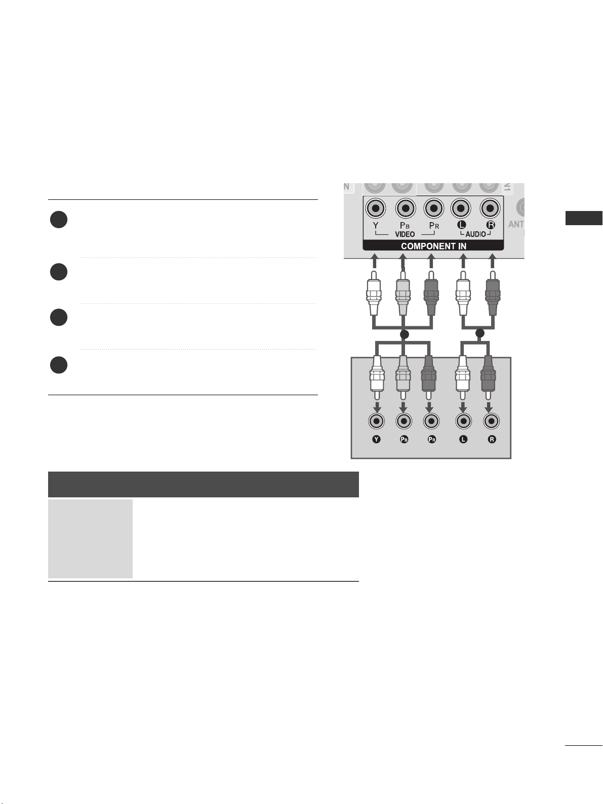
Connecting with a component cable
Signal
480i / 576i
480p / 576p
720p / 1080i
10 8 0 p
Component
O
O
O
O
(50 Hz / 60 Hz only)
HDMI
X
O
O
O
(24 Hz / 30 Hz / 50 Hz / 60 Hz)
Connect the video outputs (Y, PB, PR
)
of the digital set
top box to the
CCOO MMPP OONN EE NNTT IINN VVIIDDEEOO
jacks on the
TV.
Connect the audio output of the digital set-top box to
the
CCOO MMPP OONN EE NNTT IINN AA UUDDIIOO
jacks on the TV.
Turn on the digital set-top box.
(
Refer to the owner’s manual for the digital set-top box.
)
Select
CCoomm ppoo nneenn tt
input source using the
IINNPPUUTT
button on the remote control.
2
3
4
1
1
2
Page 20

18
EXTERNAL EQUIPMENT SETUP
EXTERNAL EQUIPMENT SETUP
EXTERNAL EQUIPMENT SETUP
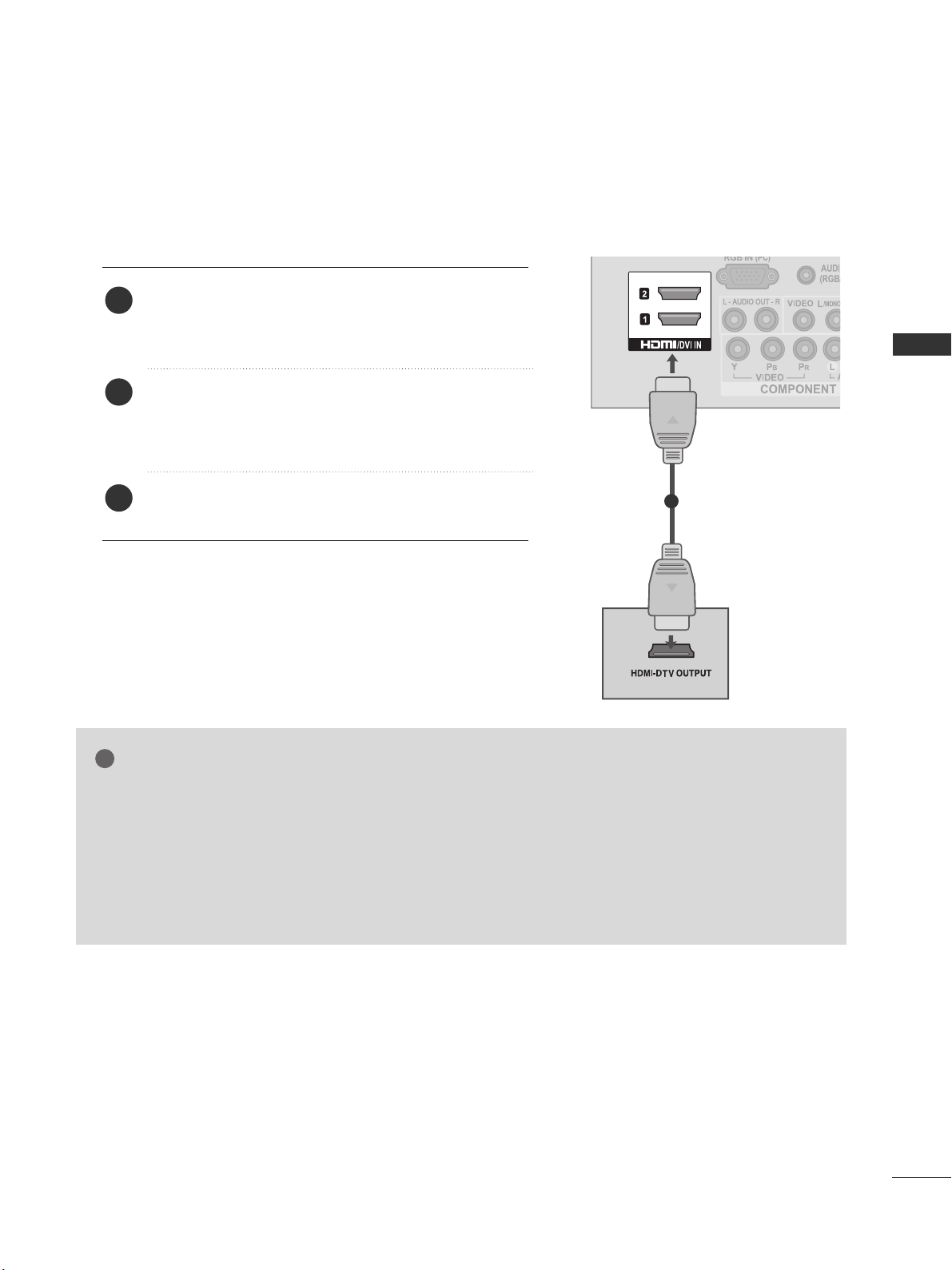
Connecting a set-top box with an HDMI cable
Connect the digital set-top box to
HH DDMM II //DDVVII IINN 11
,
HH DDMM II //DDVVII IINN 22
(Except 22LK3**)
or
HH DDMM II IINN 33
(Only
32/42LK4**)
jack on the TV.
Turn on the digital set-top box.
(
Refer to the owner’s manual for the digital set-top box.
)
Select
HH DDMM II11, HH DDMM II22
(Except 22LK3**)
or
HH DDMM II33
(Only 32/42LK4**)
input source using the
IINNPPUUTT
button on the remote control.
2
3
1
GG
Check that your HDMI cable is High Speed HDMI Cable.
If the HDMI cables are not High Speed HDMI Cable,
flickering or no screen display can result. Please use the
High Speed HDMI Cable.
GG
We recommed less than 10m for HDMI cable, and recommend to use amplifier or repeater for more than that.
NOTE
!
1
Page 21
19
EXTERNAL EQUIPMENT SETUP
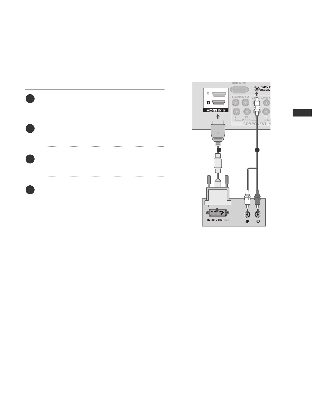
Connecting with a HDMI to DVI cable
Connect the digital set-top box to
HH DDMM II //DDVVII II NN 11
jack on the TV.
Connect the audio output of the digital set-top box to
the
AA UUDDIIOO IINN ((RR GGBB//DDVVII))
jack on the TV.
Turn on the digital set-top box. (Refer to the owner’s
manual for the digital set-top box.
)
Select
HH DDMM II11
input source using the
IINNPP UU TT
button
on the remote control.
2
3
4
1
1
2
Page 22

20
EXTERNAL EQUIPMENT SETUP
EXTERNAL EQUIPMENT SETUP
DVD SETUP
Connecting with a component cable
Component Input ports
To achieve better picture quality, connect a DVD player to the component input ports as shown below.
Component ports on the TV
YPB PR
Video output ports
on DVD player
Y
Y
Y
Y
P
B
B-Y
Cb
Pb
PR
R-Y
Cr
Pr
Connect the video outputs (Y, PB, PR
)
of the DVD to the
CCOO MMPP OONN EE NNTT IINN VVIIDDEEOO
jacks on the TV.
Connect the audio outputs of the DVD to the
CCOO MMPP OONN EE NNTT IINN AA UUDDIIOO
jacks on the TV.
Turn on the DVD player, insert a DVD.
Select
CCoommppoo nneenntt
input source using the
IINNPP UU TT
button on the remote control.
Refer to the DVD player's manual for operating instructions.
2
3
4
5
1
1
2
Page 23
21
EXTERNAL EQUIPMENT SETUP
Connecting the HDMI cable
Connect the HDMI output of the DVD to the
HH DDMM II //DDVVII IINN 11,HH DDMM II //DDVVII IINN 22
(Except 22LK3**)
or
HH DDMM II IINN 33
(Only 32/42LK4**)
jack on the TV.
Select
HH DDMM II11, HH DDMM II22
(Except 22LK3**)
or
HH DDMM II33
(Only 32/42LK4**)
input source using the
IINNPPUUTT
button on the remote control.
Refer to the DVD player's manual for operating instructions.
2
3
1
GG
The TV can receive video and audio signals simultaneously when using a HDMI cable.
GG
If the DVD does not support Auto HDMI, you must set the output resolution appropriately.
GG
Check that your HDMI cable is High Speed HDMI Cable.
If the HDMI cables are not High Speed HDMI Cable, flickering or no screen display can result.
Please use the High Speed HDMI Cable.
GG
We recommed less than 10m for HDMI cable, and recommend to use amplifier or repeater for
more than that.
NOTE
!
1
Page 24
22
EXTERNAL EQUIPMENT SETUP
EXTERNAL EQUIPMENT SETUP
VCR SETUP
■
To avoid picture noise (interference), allow adequate distance between the VCR and TV.
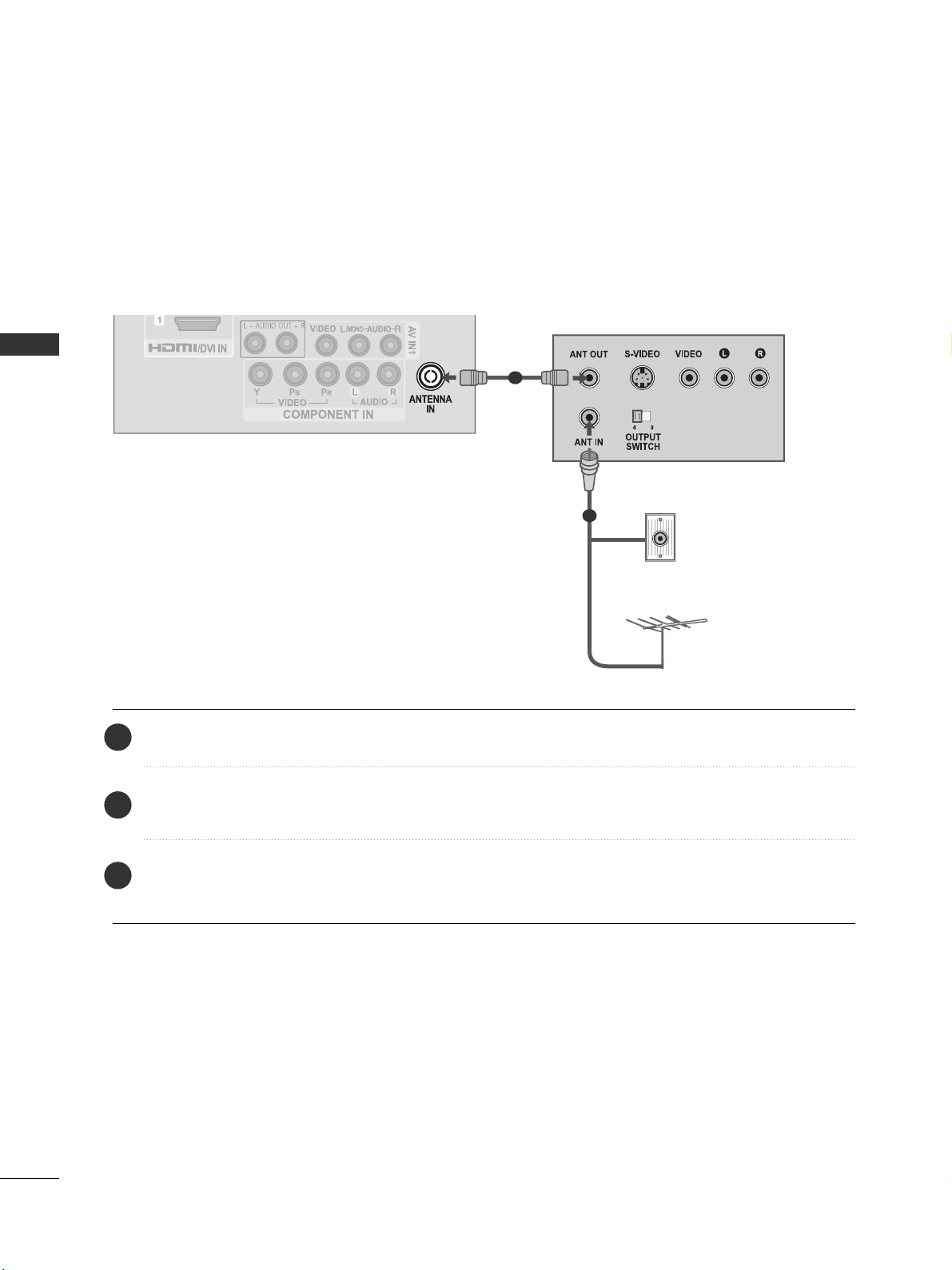
Connecting with a RF Cable
Connect the
AA NNTT OOUUTT
socket of the VCR to the
AA NNTTEENNNN AA II NN
socket on the TV.
Connect the antenna cable to the
AA NNTT IINN
socket of the VCR.
Press the
PP LLAAYY
button on the VCR and match the appropriate channel between the TV and VCR for
viewing.
2
3
1
Wall Jack
Antenna
1
2
Page 25

23
EXTERNAL EQUIPMENT SETUP
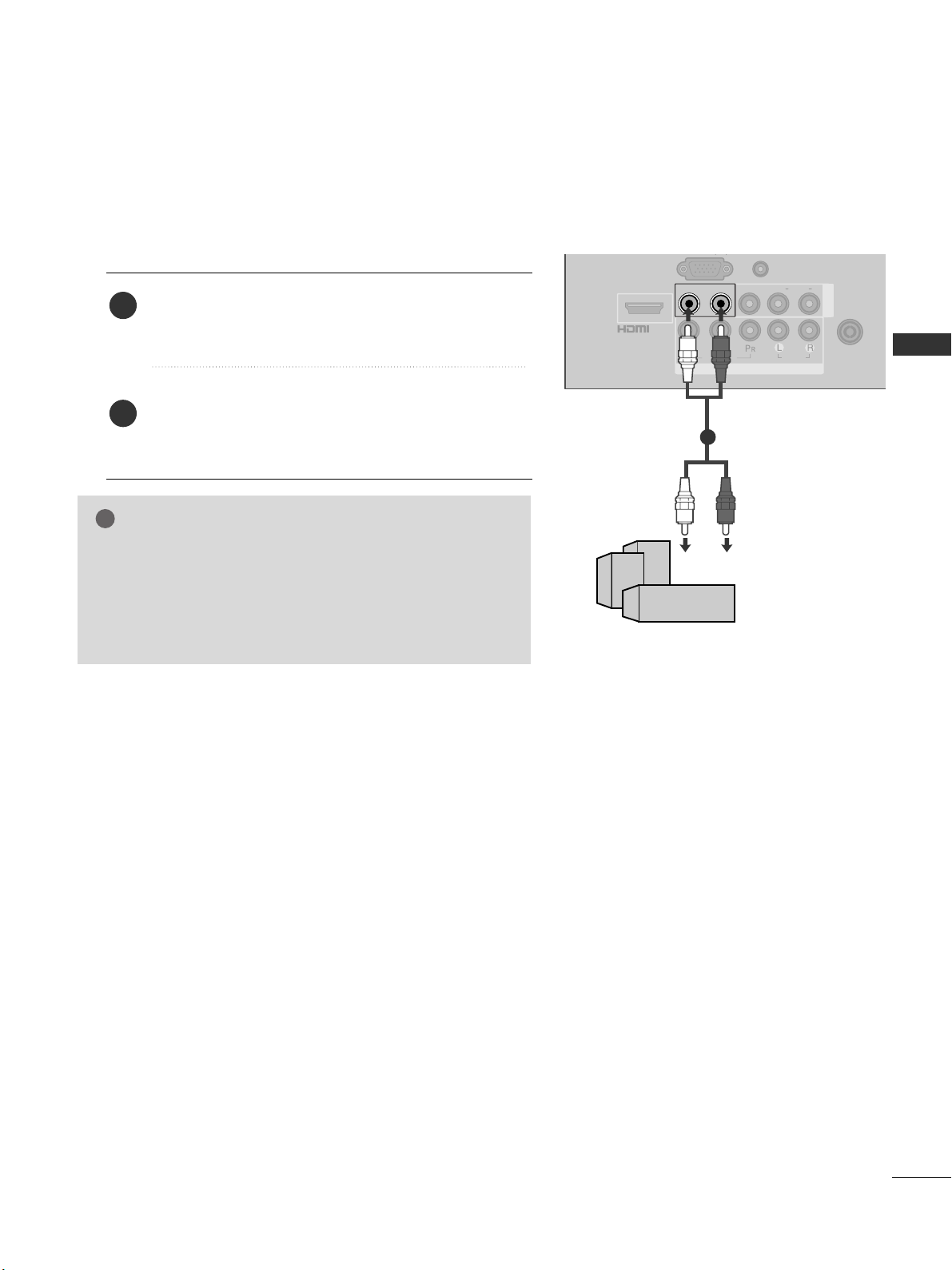
Connecting with a RCA cable
Connect the
AA UU DD IIOO/VVIIDDEEOO
jacks between TV and
VCR. Match the jack colours (Video = yellow, Audio Left
= white, and Audio Right = red)
Insert a video tape into the VCR and press PLAY on
the VCR. (Refer to the VCR owner’s manual.
)
Select
AAVV 11
input source using the
IINNPPUUTT
button on
the remote control.
If connected to
AA VV IINN22
, select
AA VV22
input source.
1
2
3
GG
If you have a mono VCR, connect the audio cable from the
VCR to the
AA UU DDIIOO LL//MMOONN OO
jack of the TV.
NOTE
!
USB IN SETUP
■
Image shown may differ from your TV.
Connect the USB device to the
UU SSBB IINN
jacks on the side of TV.
After connecting the
UU SSBB IINN
jacks, you use the
UU SS BB
function. (
GG
pp..5533
)
2
1
1
1
Page 26

24
EXTERNAL EQUIPMENT SETUP
EXTERNAL EQUIPMENT SETUP
EXTERNAL EQUIPMENT SETUP
OTHER A/V SOURCE SETUP
Connect the
AA UU DDIIOO/VVIIDDEEOO
jacks between TV and external equipment. Match the jack colours
.
(
Video = yellow, Audio Left = white, and Audio Right = red
)
Select
AAVV 11
input source with using the
IINNPP UU TT
button on the remote control.
If connected to
AA VV IINN22
, select
AA VV22
input source.
Operate the corresponding external equipment.
Refer to external equipment operating guide.
1
2
3
Camcorder
Video Game Set
1
Page 27
COMPONENT IN
AUDIO
VIDEO
ANTENNA
IN
L(L(MONO)MONO)
R
AUDIOAUDIO
VIDEOVIDEOL - AUDIO OUT - RL - AUDIO OUT - R
AV IN
AUDIO IN
(RGB/DVI)
/DVI IN
G
(C)
25
EXTERNAL EQUIPMENT SETUP
EXTERNAL STEREO SETUP
GG
When connecting with external audio equipments, such as
amplifiers or speakers, please turn the TV speakers off.
(
GG
pp ..8877
)
GG
This function works in following mode : RF, AV,
Component, RGB, HDMI, USB.
NOTE
!
Use to connected either an external amplifier, or add a sub-woofer
to your surround sound system.
Connect the input jack of the stereo amplifier to the
AA UUDDIIOO OO UUTT
jacks on the TV.
Set up your speakers through your analog stereo
amplifier, according to the instructions provided with
the amplifier.
2
1
11
Page 28

26
EXTERNAL EQUIPMENT SETUP
EXTERNAL EQUIPMENT SETUP
PC SETUP
This TV provides Plug and Play capability, meaning that the PC
adjusts automatically to the TV's settings.
Connecting with a D-sub 15 pin cable
1 2
4
Connect the RGB output of the PC to the
RRGG BB II NN
(( PP CC ))
jack on the TV.
Connect the PC audio output to the
AA UU DDIIOO IINN
(( RR GGBB//DDVVII))
jack on the TV.
Turn on the TV and the PC.
Select
RRGG BB
input source using the
IINNPP UU TT
button on
the remote control.
2
3
1
Page 29

27
EXTERNAL EQUIPMENT SETUP
NOTE
!
GG
Avoid keeping a fixed image on the TV ’s screen
for prolonged periods of time.The fixed image
may become permanently imprinted on the
screen use a screen saver when possible.
GG
There may be interference relating to resolution,
vertical pattern, contrast or brightness in PC
mode. Change the PC mode to another resolution or change the refresh rate to another rate
or adjust the brightness and contrast on the
menu until the picture is clear. If the refresh rate
of the PC graphic card can not be changed,
change the PC graphic card or consult the manufacturer of the PC graphic card.
GG
The synchronization input waveform for
Horizontal and Vertical frequencies are separate.
GG
If the resolution of PC is over SXGA, there will
be no picture on the TV.(only HD Models)
GG
Connect the audio cable from the PC to the
Audio input on the TV.(Audio cables are not
included with the TV).
GG
If you use too long an RGB-PC cable, there may
be interference on the screen. We recommend
using under 5m of the cable. This provides the
best picture quality.
GG
We recommend using 1360 x 768, 60 Hz (Only
22/26/32LK3**), 1920 x 1080, 60 Hz (Only
32/42LK4**) for the PC mode, these should
provide the best picture quality.
GG
HDMI mode supports PCM audio format only.
GG
If the Audio setting is set to
Dolby/DTS/Bitstream in some DVDP/STB, make
sure to change the setting to PCM.
Resolution
720x480
720x576
1280x720
1920x1080i
1920x1080p
HDMI-DTV mode
Horizontal Vertical
Frequency(kHz) Frequency(Hz)
31.47 59.94
31.50 60.00
31.25 50.00
44.96 59.94
45.00 60.00
37.50 50.00
33.75 60.00
33.72 59.94
28.125 50.00
67.432 59.94
67.5 60
56.250 50
27 24
33.75 30
Resolution
640x350
720x400
640x480
800x600
1024x768
1280x768
1360x768
1280x1024
1920x1080
RGB-PC mode
Horizontal Vertical
Frequency(kHz) Frequency(Hz)
31.468 70.09
31.469 70.09
31.469 59.94
37.879 60.317
48.363 60.004
47.776 59.87
47.720 59 .799
63.668 59.895
66.587 59.934
Only 32/42LK4**
Supported Display Resolution
Page 30

28
EXTERNAL EQUIPMENT SETUP
EXTERNAL EQUIPMENT SETUP
EXTERNAL EQUIPMENT SETUP
Screen Setup for PC mode
Returns Position, Size and Phase to the factory default settings.
This function works in the following mode : RGB[PC], Component(except 480i, 576i).
Screen Reset
To Set
Auto Config.
Screen
Move
Prev.
Resolution
Position
Size
Phase
Reset
G
OK
Move
• Contrast 90
• Brightness 50
• Sharpness 60
• Colour 60
• Tint 0
• Advanced Control
• Picture Reset
Screen
PICTURE
RG
E
Screen
Yes No
1
Select
PP IICC TTUURR EE
.
Select
SS cc rreeeenn
.
3
Select
RReesseett
.
2
OK
OK
Select
YYeess
.
Run
RReesseett
.
4
OK
5
OK
• Press the
HHOOMMEE//EEXXIITT
button to return to normal TV viewing.
• Press the
BBAACC KK
button to move to the previous menu screen.
1
Page 31

29
EXTERNAL EQUIPMENT SETUP
If the picture is not clear after auto adjustment and especially if characters are still trembling, adjust the
picture phase manually.
PPoo ssiittiioonn
operates in Component(except 480i, 576i), RGB mode.
SSiizzee,PP hhaassee
operate only in RGB mode.
Adjustment for screen Position, Size, Phase
Auto Config.
Resolution
Position
G
Size
Phase
Reset
GF
D
E
Screen
Move
Prev.
OK
Move
• Contrast 90
• Brightness 50
• Sharpness 60
• Colour 60
• Tint 0
• Advanced Control
• Picture Reset
Screen
PICTURE
RG
E
Screen
• Press the
HHOOMMEE//EEXXIITT
button to return to normal TV viewing.
• Press the
BBAACC KK
button to move to the previous menu screen.
Select
PP IICC TTUURR EE
.
Select
SS cc rreeeenn
.
Select
PP oossii tt iioonn, SS ii zz ee
or
PP hhaassee
.
Make appropriate adjustments.
3
4
2
OK
OK
1
Page 32

30
EXTERNAL EQUIPMENT SETUP
EXTERNAL EQUIPMENT SETUP
To view a normal picture, match the resolution of RGB mode and selection of PC mode.
This function works in the following mode: RGB[PC]
Selecting Resolution
Auto Config.
Resolution
G
Position
Size
Phase
Reset
Screen
Move
Prev.
1024 x 768
1280 x 768
1360 x 768
OK
Move
• Contrast 90
• Brightness 50
• Sharpness 60
• Colour 60
• Tint 0
• Advanced Control
• Picture Reset
Screen
PICTURE
RG
E
Screen
• Press the
HHOOMMEE//EEXXIITT
button to return to normal TV viewing.
• Press the
BBAACC KK
button to move to the previous menu screen.
Select
PP IICC TTUURR EE
.
Select
SS cc rreeeenn
.
Select
RReessoolluuttii oonn
.
Select the desired resolution.
3
4
2
OK
OK
1
Page 33

31
EXTERNAL EQUIPMENT SETUP
Automatically adjusts the picture position and minimizes image instability. After adjustment, if the image is
still not correct, your TV is functioning properly but needs further adjustment.
AAuuttoo ccoo nnffiigguurr ee
This function is for automatic adjustment of the screen position, size, and phase.
The displayed image will be unstable for a few seconds while the auto configuration is in progress.
Auto Configure (RGB [PC] mode only)
• If the position of the image is still not correct,
try Auto adjustment again.
• If picture needs to be adjusted again after Auto
adjustment in RGB(PC), you can adjust the
PP oossii tt iioonn, SS ii zz ee
or
PP hhaassee
.
Auto Config.
G
Resolution
Position
Size
Phase
Reset
Screen
Move
Prev.
To Set
Yes No
OK
Move
• Contrast 90
• Brightness 50
• Sharpness 60
• Colour 60
• Tint 0
• Advanced Control
• Picture Reset
Screen
PICTURE
RG
E
Screen
• Press the
HHOOMMEE//EEXXIITT
button to return to normal TV viewing.
• Press the
BBAACC KK
button to move to the previous menu screen.
Select
PP IICC TTUURR EE
.
Select
SS cc rreeeenn
.
Select
AA uu ttoo CCoonnffiigg..
.
3
2
OK
OK
Select
YYeess
.
Run
AA uu ttoo CCoonnffiigg..
.
4
OK
5
OK
1
Page 34

32
WATCHING TV / PROGRAMME CONTROL
WATCHING TV / PROGRAMME CONTROL
rr
(POWER)
ENERGY SAVING
AV MODE
INPUT
TV
Switches the TV on from standby or off to standby.
Adjust the power saving mode of the TV.
It helps you select and set images and sounds when
connecting AV devices.(
GG
pp ..55 22
)
External input mode rotate in regular sequence.
Selects TV channel.
0 to 9 number
button
LIST
Q.VIEW
VOLUME UP
/DOWN
MARK/FAV
RATIO
MUTE
Programme
UP/DOWN
PAGE
UP/DOWN
Selects a programme.
Selects numbered items in a menu.
Displays the programme table.
Returns to the previously viewed programme.
Adjusts the volume.
Displays the selected favourite programme.
Selects your desired picture format.
Switches the sound on or off.
Selects a programme.
Move from one full set of screen information to the next
one.
Coloured
buttons
These buttons are used for teletext (on
TT EE LLEE TT EEXXTT
models only),
PPrr ooggrr aamm mm ee eeddiitt
.
REMOTE CONTROL KEY FUNCTIONS
((
OOnnllyy 2222// 2266 //3322LLKK33****,, 3322// 4422 LL KK44****))
When using the remote control, aim it at the remote control sensor on the TV.
TELETEXT
BUTTONS
These buttons are used for teletext.
For further details, see the ‘Teletext’ section.(
GG
pp ..99 44
)
1
1
Home
Page 35

33
WATCHING TV / PROGRAMME CONTROL
Installing Batteries
■
Open the battery compartment cover on the back and install the
batteries matching correct polarity (+with +,-with -).
■
Install two 1.5V AAA batteries. Do not mix old or used batteries with
new ones.
■
Close cover.
■
To remove the batteries, perform the installation actions in reverse.
X STUDIO
HOME
Q. MENU
BACK
EXIT
THUMBSTICK
(Up/Down/Left/Right)
OK
Controls the USB menu.
Selects a menu.
Clears all on-screen displays and returns to TV viewing
from any menu..
Select the desired quick menu source.(
GG
pp ..33 77
)
Allows the user to move return one step in an interactive
application or other user interaction function.
See a list of AV devices connected to TV.
When you toggle this button, the Simplink menu appears
at the screen.(
GG
pp ..44 88
)
Clears all on-screen displays and returns to TV viewing
from any menu.
Allows you to navigate the on-screen menus and adjust
the system settings to your preference.
Accepts your selection or displays the current mode.
SIMPLINK
Menu
control buttons
Controls SIMPLINK menu.
Home
Page 36

34
WATCHING TV / PROGRAMME CONTROL
WATCHING TV / PROGRAMME CONTROL
REMOTE CONTROL KEY FUNCTIONS
((
OOnnllyy 1199//22 22//2266//3322LLVV22 ******))
When using the remote control, aim it at the remote control sensor on the TV.
rr
(POWER)
ENERGY SAVING
AV MODE
INPUT
TV
Switches the TV on from standby or off to standby.
Adjust the power saving mode of the TV.
It helps you select and set images and sounds when
connecting AV devices.(
GG
pp ..55 22
)
External input mode rotate in regular sequence.
Selects TV channel.
0 to 9 number
button
LIST
Q.VIEW
VOLUME UP
/DOWN
MARK/FAV
RATIO
MUTE
Programme
UP/DOWN
PAGE
UP/DOWN
Selects a programme.
Selects numbered items in a menu.
Displays the programme table.
Returns to the previously viewed programme.
Adjusts the volume.
Displays the selected favourite programme.
Selects your desired picture format.
Switches the sound on or off.
Selects a programme.
Move from one full set of screen information to the next
one.
Coloured
buttons
These buttons are used for teletext (on
TT EE LLEE TT EEXXTT
models only),
PPrr ooggrr aamm mm ee eeddiitt
.
TELETEXT
BUTTONS
These buttons are used for teletext.
For further details, see the ‘Teletext’ section.(
GG
pp ..99 44
)
1
1
Home
Page 37

35
WATCHING TV / PROGRAMME CONTROL
Installing Batteries
■
Open the battery compartment cover on the back and install the
batteries matching correct polarity (+with +,-with -).
■
Install two 1.5V AAA batteries. Do not mix old or used batteries with
new ones.
■
Close cover.
■
To remove the batteries, perform the installation actions in reverse.
X STUDIO
HOME
Q. MENU
BACK
EXIT
THUMBSTICK
(Up/Down/Left/Right)
OK
Controls the USB menu.
Selects a menu.
Clears all on-screen displays and returns to TV viewing
from any menu..
Select the desired quick menu source.(
GG
pp ..33 77
)
Allows the user to move return one step in an interactive
application or other user interaction function.
See a list of AV devices connected to TV.
When you toggle this button, the Simplink menu appears
at the screen.(
GG
pp ..44 88
)
Clears all on-screen displays and returns to TV viewing
from any menu.
Allows you to navigate the on-screen menus and adjust
the system settings to your preference.
Accepts your selection or displays the current mode.
SIMPLINK
Menu
control buttons
Controls SIMPLINK menu.
Home
Page 38

36
WATCHING TV / PROGRAMME CONTROL
WATCHING TV / PROGRAMME CONTROL
TURNING ON THE TV
Firstly, connect the power cord correctly.
At this stage, the TV switches to standby mode.
In standby mode to turn TV on, press the
rr
/ I, INPUT or P button on the TV or press the
POWER, INPUT, P or NUMBER button on the remote control and the TV will switch on.
2
1
Initializing setup
Note:
a. If you close without completing the initial setting, the Initial Setting menu can be displayed again.
b. “Store Demo” mode is only for shop display and not for general customer use.
c. "Home Use” mode is the optimal setting for home environments, and is the TV's default mode.
d. "Store Demo" mode is the optimal setting for store environments. If a user modifies image quality data,
“Store Demo” mode initializes the product to the image quality set by us after a certain period of time.
e. The mode (Home Use, Store Demo) can be changed by executing Mode Setting in the OPTION menu.
If the OSD (On Screen Display) is displayed on the screen after turning on the TV, you can adjust the
LLaann gg uu aaggee, MMooddee SS ee ttttiinngg, AA uu ttoo TTuunniinn gg
.
- When your TV is turned on, you will be able to use its features.
PROGRAMME SELECTION
Press the
PP
or NUMBER buttons to select a programme
number.
1
VOLUME ADJUSTMENT
Press the
++ or--
button to adjust the volume.
If you wish to switch the sound off, press the MUTE button.
You can cancel this function by pressing the MUTE,
++ or--
, AV Mode button.
1
Page 39

37
WATCHING TV / PROGRAMME CONTROL
•
AA sspp eecctt RRaattiioo
: Selects your desired picture format.
For Zoom Setting, select 16:9, Original, 4:3, 14:9,
Zoom and Cinema Zoom in Ratio Menu. After completing Zoom Setting, the display goes back to
Q.Menu.
•
CClleeaarr VVoo iiccee llll
: By differentiating the human sound
range from others, it helps users listen to human voices better.
•
PPii cc ttuurree MM ooddee
: Selects your desired Picture Mode.
•
SSoo uu nndd MM oodd ee
: It is a feature to automatically set
the sound combination which it deems the best for
the images being watched. Selects your desired
Sound Mode.
•
AA UU DDIIOO
: Selects the sound output.
•
SSlleeeepp TTiimmeerr
: Sets the sleep timer.
•
FFaavv oouu rriittee
: Selects the favourite On or Off.
•
UU SSBB DDeevv iiccee
: Selects “Eject” in order to eject USB
device.
QUICK MENU
Your TV's OSD (On Screen Display) may differ slightly from that shown in this manual.
Q.Menu (Quick Menu) is a menu of features which users might use frequently.
•
Press the
QQ..MM EENNUU
button to return to normal TV viewing.
Q.Menu
Close
3
FF
16:9
GG
Zoom Setting
Standard
Standard
MONO
Off
Eject
Aspect Ratio
Clear Voice ll
Picture Mode
Sound Mode
AUDIO
Sleep Timer
Favourite
USB Device
Off
Display each menu.
Select your desired Source.
1
3
2
OK
Q.MENU
PR
Page 40

38
WATCHING TV / PROGRAMME CONTROL
WATCHING TV / PROGRAMME CONTROL
ON SCREEN MENUS SELECTION AND ADJUSTMENT
■
Image shown may differ from your TV.
Your TV's OSD (On Screen Display) may differ slightly from that shown in this manual.
SETUP
OPTION
PICTURE AUDIO
TIME
OK
Move
Auto Tuning
Manual Tuning
Programme Edit
SETUP
OK
Move
Aspect Ratio : 16:9
Energy Saving : Off
Picture Mode : Vivid
• Backlight 100
• Contrast 100
• Brightness 50
• Sharpness 70
• Colour 70
PICTURE
E
OK
Move
Auto Volume : Off
Clear Voice ll : Off
•
Level
0
Balance 0
Sound Mode : Standard
• Infinite Surround : Off
• Treble 50
• Bass 50
AUDIO
E
LR
-+
OK
Move
Menu Language : English
Input Label
SIMPLINK : On
Key Lock : Off
Set ID : 1
Power Indicator
Demo Mode : Off
Mode Setting : Home Use
OPTION
E
OK
Move
Clock
Off Time : Off
On Time : Off
Sleep Timer : Off
TIME
USB
Display each menu.
Select a menu item.
Move to the pop up menu.
3
2
OK
OK
• Press the
HHOOMMEE//EEXXIITT
button to return to normal TV viewing.
• Press the
BBAACC KK
button to move to the previous menu screen.
OK
Move
Photo List
Music List
Movie List
DivX Reg. Code
Deactivation
USB
1
Page 41

39
WATCHING TV / PROGRAMME CONTROL
OK
Move
Auto Tuning
Manual Tuning
Programme Edit
SETUP
Auto Tuning
AUTO PROGRAMME TUNING
Use this to automatically find and store all available programmes.
When you start auto programming, all previously stored service information will be deleted.
• If you wish to keep on auto tuning select
YYeess
using the button. Then, press the OK button. Otherwise select
NN oo
.
Check your antenna connection. The previous channel
information will be updated during Auto Tuning.
Yes No
OK
Move
Auto Tuning
Manual Tuning
Programme Edit
SETUP
Auto Tuning
• Press the
HHOOMMEE//EEXXIITT
button to return to normal TV viewing.
• Press the
BBAACC KK
button to move to the previous menu screen.
Select
SS EETTUUPP
.
Select
AA uu ttoo TTuunniinn gg
.
Select
YYeess
.
Run
AA uu ttoo ttuunniinn gg
.
3
2
OK
OK
4
OK
1
Page 42

40
WATCHING TV / PROGRAMME CONTROL
WATCHING TV / PROGRAMME CONTROL
OK
Move
Auto Tuning
Manual Tuning
Programme Edit
SETUP
Manual Tuning
Manual Tuning lets you manually tune and arrange the stations in whatever order you desire.
•
BBGG
: PAL B/G, SECAM B/G (Asia / New Zealand / M.East / Africa)
II
: PAL I/II (Hong Kong / South Africa)
DD KK
: PAL D/K, SECAM D/K (China / Africa)
MM
: Philippines
•
To store another channel, repeat steps 3 to 9.
Storage
FF 1GG
System
BG
Band
V/UHF
Channel
Fine
FF GG
FF GG
Search
0
Name
C 02
Close
Store
MANUAL PROGRAMME TUNING
OK
Move
Auto Tuning
Manual Tuning
Programme Edit
SETUP
Manual Tuning
• Press the
HHOOMMEE//EEXXIITT
button to return to normal TV viewing.
• Press the
BBAACC KK
button to move to the previous menu screen.
Select
SS EETTUUPP
.
Select
MMaann uu aall TT uunn iinn gg
.
Select the desired programme number on.
Select a TV system.
Select
VV//UUHH FF
or
CCaabb llee
.
Commence searching.
Select the desired
channel number.
or
Select
SS tt oorr ee
.
3
2
OK
4
or
5
6
7
123
4506
789
8
OK
OK
9
OK
123
4506
789
1
Page 43

41
WATCHING TV / PROGRAMME CONTROL
Normally fine tuning is only necessary if reception is poor.
A Fine Tuning
You can assign a station name with five characters to each programme number.
A Assigning a station name
OK
Move
Auto Tuning
Manual Tuning
Programme Edit
SETUP
Manual Tuning
Storage
FF 1GG
System
BG
Band
V/UHF
Channel
Fine
FF GG
FF GG
Search
0
Name
C 02
Close
Store
OK
Move
Auto Tuning
Manual Tuning
Programme Edit
SETUP
Manual Tuning
• Press the
HHOOMMEE//EEXXIITT
button to return to normal TV viewing.
• Press the
BBAACC KK
button to move to the previous menu screen.
Select
SS EETTUUPP
.
Select
MMaann uu aall TT uunn iinn gg
.
5
Select
SS tt oorr ee
.
2
OK
4
Select the position and
make your choice of
the second character,
and so on.
You can use an the
alphabet AAto ZZ, the
number 00to 99, +/ -,
and blank.
OK
OK
Select
NN aa mm ee
.
3
OK
6
OK
OK
Select
FFiinnee
.
Select
SS EETTUUPP
.
Select
MMaann uu aall TT uunn iinn gg
.
Select
SS tt oorr ee
.
5
Fine tune for the best picture and
sound.
2
OK
3
4
OK
6
OK
OK
1
1
Page 44

42
WATCHING TV / PROGRAMME CONTROL
WATCHING TV / PROGRAMME CONTROL
PROGRAMME EDIT
When a programme number is skipped, it means that you will be unable to select it using P button during TV
viewing.
If you wish to select the skipped programme, directly enter the programme number with the NUMBER buttons or
select it in the Programme edit menu.
This function enables you to skip the stored programmes.
C 011
Pr. Change
Page Change
P
TV
0 1 C 01
2 C 05
3 BLN 2
4 5
6 7
8 9
10 11
12 13
14 15
E
Navigation
Previous
Skip
OK
Move
Auto Tuning
Manual Tuning
Programme Edit
SETUP
Programme Edit
Move
Delete
• Press the
HHOOMMEE//EEXXIITT
button to return to normal TV viewing.
• Press the
BBAACC KK
button to move to the previous menu screen.
Select
SS EETTUUPP
.
Select
PPrr ooggrraamm mm ee EEddiitt
.
Enter the
PPrr ooggrraamm mm ee EEddiitt
.
Select a programme to be stored or skipped.
3
2
OK
OK
4
1
Page 45

43
WATCHING TV / PROGRAMME CONTROL
This function enables you to delete or skip the stored programmes.
You can also move some channels and use other programme numbers.
A Deleting a programme
Select a programme number to be deleted.
2
RED
RED
Turn the deleted programme number to RED.
3
RED
RED
Release the deleted programme.
A Skipping a programme number
Select a programme number to be skipped.
2
Turn the skipped programme number to BLUE.
3
Release the skipped programme.
1
• The selected programme is deleted, all the
following programmes are shifted up one
position.
• When a programme number is skipped it
means that you will be unable to select it using
the P button during normal TV viewing.
• If you wish to select a skipped programme, directly
enter the programme number with the NUMBER
buttons or select it in the programme edit.
1
A Moving a programme
Select a programme number to be moved.
Turn the moved programme number to YELLOW.
3
YELL
YELLOOWW
Release the moved programme.
1
2
YELL
YELLOOWW
BLUE
BLUE
Page 46

44
WATCHING TV / PROGRAMME CONTROL
WATCHING TV / PROGRAMME CONTROL
SELECTING THE PROGRAMME LIST
You can check which programmes are stored in the memory by displaying the programme list.
Display the Programme List.
Select a programme.
Switch to the chosen programme number.
1
A Displaying programme list
A Selecting a programme in the programme list
• You may find some blue programmes. These
have been set up to be skipped by auto programming or in the programme edit mode.
• Some programmes with the channel number
shown in the programme LIST indicate there is
no station name assigned.
Turn the pages.
2
Return to normal TV viewing.
A Paging through a programme list
Programme List
1 C 01
2 C 05
3 BLN 2
1
Exit
LIST
2
1
OK
LIST
Page 47

45
WATCHING TV / PROGRAMME CONTROL
FAVOURITE PROGRAMME SETUP
Favorite programmes is a convenient feature that lets you quickly scan up to programmes of your choice without
having to wait for the TV to scan through all the in-between programmes.
To tune to a favorite programme, press the
FFAAVV
(Favorite)button repeatedly.
A
Displaying the favourite programme
list
A Selecting favourite programme
• This will automatically include the selected programme into your favourite programme list.
1 C 01
2 C 05
3 BLN 2
Exit
Favorite List
Select your desired programme.
Select
FFaavv oouurr iittee
.
123
4506
789
2
Q.MENU
4
Q.MENU
3
1
or
Select
FFaavv oouurr ii tt ee..
Return to TV viewing.
1
Display the Favourite Programme
List
.
MARK
FAV
Q.Menu
Close
3
16:9
Zoom Setting
Standard
Standard
MONO
Off
Eject
Aspect Ratio
Clear Voice ll
Picture Mode
Sound Mode
AUDIO
Sleep Timer
Favourite
USB Device
FF
Favourite
GG
PR
Page 48

46
WATCHING TV / PROGRAMME CONTROL
WATCHING TV / PROGRAMME CONTROL
INPUT LIST
•
TT VV
: Select it when watching the TV.
•
AA VV
: Select it when watching the VCR or external equipment.
•
CC oo mm ppoonneenntt
: Select it when using DVD or Digital set-top box depends on connector.
•
RR GGBB
:Select it when using PC depends on connector.
•
HH DDMMII
: Select it when using DVD or Digital set-top box depend on connector.
Component
HDMI2 HDMI1
RGB
TV AV1
■
Image shown may differ from your TV.
Select the input source.
1
INPUT
OK
AV2
HDMI3
Except 22LK3**
Except 22LK3**
Only 32/42LK4**
Page 49

47
WATCHING TV / PROGRAMME CONTROL
INPUT LABEL
Selects a label for each input source.
OK
Move
Menu Language : English
Input Label
SIMPLINK : On
Key Lock : Off
Set ID : 1
Power Indicator
Demo Mode : Off
Mode Setting : Home Use
OPTION
E
Input Label
OK
Move
Menu Language : English
Input Label
SIMPLINK : On
Key Lock : Off
Set ID : 1
Power Indicator
Demo Mode : Off
Mode Setting : Home Use
OPTION
E
Input Label
FF GG
Close
• Press the
HHOOMMEE//EEXXIITT
button to return to normal TV viewing.
• Press the
BBAACC KK
button to move to the previous menu screen.
Select
OOPPTTIIOONN
.
Select
IInnppuutt LLaabbeell
.
Select the source.
Select the label.
OK
OK
3
2
4
Only 32/42LK4**
Except 22LK3**
Except 22LK3**
AV1
AV2
Component
RGB
HDMI1
HDMI2
HDMI3
1
Page 50

48
WATCHING TV / PROGRAMME CONTROL
WATCHING TV / PROGRAMME CONTROL
NOTE
!
GG
Connect the HDMI/DVI IN or HDMI IN terminal of the TV to the rear terminal and Side terminal (HDMI
terminal) of the SIMPLINK device with the HDMI cable.
GG
When you switch the Input source using the INPUT button on the remote control, you can stop the
operation of a device controlled by SIMPLINK.
This function operates only with devices with the SIMPLINK logo.
Please check the SIMPLINK logo.
This TV might not function properly when using it with other products with HDMI-CEC function.
This allows you to control and play other AV devices connected to the display through HDMI cable without addi-
tional cables and settings.
If you do not want SIMPLINK menu,select “
OO ff ff
”.
OK
Move
Menu Language : English
Input Label
SIMPLINK : On
Key Lock : Off
Set ID : 1
Power Indicator
Demo Mode : Off
Mode Setting : Home Use
OPTION
E
SIMPLINK : On
OK
Move
Menu Language : English
Input Label
SIMPLINK : On
Key Lock : Off
Set ID : 1
Power Indicator
Demo Mode : Off
Mode Setting : Home Use
OPTION
E
SIMPLINK : On
Off
On
On
• Press the
HHOOMMEE//EEXXIITT
button to return to normal TV viewing.
• Press the
BBAACC KK
button to move to the previous menu screen.
Select
OO PPTTIIOONN
.
Select
SSIIMM PPLLIINNKK
.
Select
OO nn orOO ff ff
.
Save.
3
2
OK
OK
4
OK
1
Page 51

49
WATCHING TV / PROGRAMME CONTROL
DDiisscc ppllaayybbaacckk
Control connected AV devices by pressing the , OK,
G, A
,
ll ll
, FFand GGbuttons.
DDiirreecctt PPllaayy
After connecting AV devices to the TV, you can directly control the devices and play media without additional settings.
SSeelleecctt AAVV ddeevv iiccee
Enables you to select one of the AV devices connected to the TV and operate it.
PPoowweerr ooffff aallll ddeevviicceess
When you switch off the TV, all connected devices are turned off.
SSwwiittcchh aauuddiioo--oouutt
Offers an easy way to switch audio-out.
SSyynn cc PPoowweerr oonn
When the equipment with Simplink function connected HDMI terminal starts to play, The TV will change automatically to turn
on mode.
**
A device, which is connected to the TV through a HDMI cable but does not support SIMPLINK, does not provide this function.
Note: To operate SIMPLINK, an High Speed HDMI Cable with *CEC function should be used. (*CEC: Consumer Electronics
Control).
SIMPLINK Functions
Selected Device
When device is not connected (displayed in gray)
When a device is connected
(displayed in bright colour)
1
2
3
4
5
SIMPLINK Menu
Press the button and then OK button to select the desired SIMPLINK source.
TT VV vviieewwiinngg ::
Switch to the previous TV programme
regardless of the current mode.
DDIISS CC ppllaayybbaacckk ::
Select and play connected discs.
When multiple discs are available, the titles of discs are
conveniently displayed at the bottom of the screen.
VVCCRR pp llaayybbaacckk ::
Play and control the connected
VCR.
HH DDDD RReecc oorrddiinnggss ppllaayybbaacckk ::
Play and control
recordings stored in HDD.
AA uuddiioo OOuu tt ttoo HHoommee tthheeaatteerr//AA uuddiioo OOuutt ttoo TTVV::
Select Home theater or TV speaker for Audio Out.
1
2
3
4
5
OK
FG
Change Device
Page 52

50
WATCHING TV / PROGRAMME CONTROL
WATCHING TV / PROGRAMME CONTROL
KEY LOCK
The TV can be set so that the remote control is required to control it.
This feature can be used to prevent unauthorized viewing.
This TV is programmed to remember which option it was last set to even if you turn the TV off.
• In
KK eeyy LLoo cc kk‘OO nn
’, if the TV is turned off, press the rr/ I,
INPUT, P button on the TV or POWER, INPUT, P
or NUMBER buttons on the remote control then the set will
be turned on.
• With the
KK ee yy LLoocckk OOnn
, the display ‘
KK ee yy LLoocckk OOnn
’
appears on the screen if any button on the front panel is
pressed while viewing the TV.
OK
Move
Menu Language : English
Input Label
SIMPLINK : On
Key Lock : Off
Set ID : 1
Power Indicator
Demo Mode : Off
Mode Setting : Home Use
OPTION
E
Key Lock : Off
OK
Move
Menu Language : English
Input Label
SIMPLINK : On
Key Lock : Off
Set ID : 1
Power Indicator
Demo Mode : Off
Mode Setting : Home Use
OPTION
E
Key Lock : Off
Off
On
On
• Press the
HHOOMMEE//EEXXIITT
button to return to normal TV viewing.
• Press the
BBAACC KK
button to move to the previous menu screen.
Select
OO PPTTIIOONN
.
Select
KK eeyy LLoo cc kk
.
Select
OO nn
or
OO ff ff
.
Save.
3
2
OK
OK
4
OK
1
Page 53

51
WATCHING TV / PROGRAMME CONTROL
INITIALIZING
(RESET TO ORIGINAL FACTORY SETTINGS)
Use to quickly reset all the menu options to their original factory preset values.
This function deletes all TV programmes.
When the
FFaacc ttoorryy RReesseett
is completed, you must restart the Initializing setup.
Select
OO PPTTIIOONN
.
Select
FFaacc ttoorryy RReesseett
.
OK
Move
Input Label
SIMPLINK : On
Key Lock : Off
Set ID :1
Power Indicator
Demo Mode Off
Mode Setting : Home Use
Factory Reset
OPTION
E
Factory Reset
OK
Move
Input Label
SIMPLINK : On
Key Lock : Off
Set ID : 1
Power Indicator
Demo Mode : Off
Mode Setting : Home Use
Factory Reset
OPTION
E
Factory Reset
All user settings and channel
settings will be reset.
Still Continue?
Yes No
Select
YYeess
.
Start
FFaacc ttoorryy RReesseett
.
•
Press the
HHOOMMEE//EEXXIITT
button to return to normal TV viewing.
• Press the
BBAACC KK
button to move to the previous menu screen.
2
OK
3
OK
4
OK
1
Page 54

52
WATCHING TV / PROGRAMME CONTROL
WATCHING TV / PROGRAMME CONTROL
Off Cinema
Game Sport
AV MODE
You can select the optimal images and sounds when connecting AV devices to external input.
OO ff ff
Disables the AV MODE.
CCiinneemm aa
Optimizes video and audio for watching movies.
SS ppoorr tt
Optimizes video and audio for watching sports events.
GG aamm ee
Optimizes video and audio for playing games.
• If you select
CCiinneemm aa
in AV mode,
CCiinneemm aa
will
be selected both for
PPii ccttuurree MMoodd ee
and
SS oouunn dd
MMoo ddee
in
PP IICC TTUURR EE
menu and
AA UU DD IIOO
menu
respectively.
• If you select “
OO ff ff
” in
AA VV mmoo ddee
, the picture and
image which you initially set will be selected.
Press the
AAVV MMOODDEE
button repeatedly to
select the desired source.
•
Press the
BBAACCKK
button to return to normal TV viewing.
1
AV MODE
2
OK
Page 55

53
TO USE A USB DEVICE
TO USE A USB DEVICE
When connecting the USB device
When you connect a USB device, this pop up menu is displayed, automatically.
“POP UP MENU” will not be displayed while the OSD including Menu is activated.
In USB device, you can not add a new folder or delete the existing folder.
■
Image shown may differ from your TV.
When removing the USB device
Connect the USB device to the
UU SSBB IINN
jack
on the TV.
Select
PP HHOOTTOO LLIISS TT, MMUUSSIICC LL II SS TT
or
MMOOVVIIEE LLIISS TT
.
1
USB memory stick
PHOTO LIST MUSIC LIST
Select
EEjjeecctt
.
Select the USB device menu before removing the
USB device.
2
1
• This TV Supports on JPEG, MP3 and SD DivX.
MOVIE LIST
3
OK
Q.MENU
2
OK
Page 56

54
TO USE A USB DEVICE
TO USE A USB DEVICE
Precautions when using the USB device
GG
Only a USB storage device is recognizable.
GG
If the USB storage device is connected through a USB hub, the device is not recognizable.
GG
A USB storage device using an automatic recognition programme may not be recognized.
GG
A USB storage device which uses its own driver may not be recognized.
GG
The recognition speed of a USB storage device may depend on each device.
GG
Please do not turn off the TV or unplug the USB device when the connected USB storage device is working.
When such device is suddenly separated or unplugged, the stored files or the USB storage device may be damaged.
GG
Please do not connect the USB storage device which was artificially maneuvered on the PC. The device may
cause the product to malfunction or fail to be played. Never forget to use only a USB storage device which has
normal music files, image files or movie files.
GG
Please use only a USB storage device which was formatted as a FAT16, FAT32, NTFS file system provided with
the Windows operating system. In case of a storage device formatted as a different utility programme which is
not supported by Windows, it may not be recognized.
Data in a USB storage device cannot be deleted in the NTFS file system.
GG
Please connect power to a USB storage device which requires an external power supply. If not, the device may
not be recognized.
GG
Please connect a USB storage device with cable is offered by USB maker. If connected with cable is not offered
by USB maker or an excessively long cable, the device may not be recognized.
GG
Some USB storage devices may not be supported or operated smoothly.
GG
Please back up the important file because a data of USB device may be damaged. Data management is consumer's responsibility and in consequence the manufactures does not cover the product bearing data damage.
GG
Maximum of 999 files and 200 folders can be recognized.
GG
Data in a USB storage device cannot be aligned.
GG
Up to 128 English characters can be recognized as a file name.
GG
If the USB is connected in Standby Mode, specific hard disk will automatically be loaded when the TV is turned on.
GG
The recommended capacity is 1TB or less for a USB external hard disk and 32GB or less for USB memory.
GG
TV need more time to detect if the storage size is bigger. If the USB memory is connected in Standby Mode,
power on time would be longer than without memory.
GG
Any device with more than the recommended capacity may not work properly.
GG
If a USB external hard disk with a "Energy Saving" function does not work, turn the hard disk off and on again to
make it work properly.
GG
When using a USB HDD via the USB extension cable, connect a support electric power source.
Page 57

55
TO USE A USB DEVICE
Screen Components
The On Screen Display may be different from your TV. Images are an example to assist with the TV operation.
Moves to upper level folder
Current page/Total pages
Total number of marked photos
Corresponding buttons on the
remote control
1
3
4
2
PHOTO LIST
PHOTO(*.JPEG) supporting file
Baseline: Max 15360 x 8640
Min : 64x64
• Not support to progressive Jpeg
• You can play JPEG files only.
• Only baseline scan is supported among JPEG (SOF0, SOF1 only).
• Non-supported files are displayed in the form of bitmap.
Page 2/3
No Marked
PHOTO LIST
Up Folder
Navigation OPTION Page Change Mark Exit
1366x768, 125KB
KY101 12/10/2009
KY102 12/10/2009
JMJ001 12/10/2009
JMJ002 12/10/2009
JMJ003 12/10/2009
JMJ004 12/10/2009
KY103 12/10/2009
KY104 12/10/2009
KY105 12/10/2009
JMJ005 12/10/2009
JMJ006 12/10/2009
JMJ007 12/10/2009
JMJ008 12/10/2009
Up Folder
2 3
4
1
Select
UUSSBB
.
Select
PPHHOOTTOO LLIISSTT..
Drive1
MARK
JMJ001
2
OK
OK
1
Page 58

56
TO USE A USB DEVICE
TO USE A USB DEVICE
Photo Selection and PopUp Menu
Page 2/3
No Marked
PHOTO LIST
Up Folder
Navigation OPTION Page Change Mark Exit
1366x768, 125KB
KR101 12/10/2009
KR102 12/10/2009
JMJ001 12/10/2009
JMJ002 12/10/2009
JMJ003 12/10/2009
JMJ004
12/10/2009
KR103 12/10/2009
KR104 12/10/2009
KR105 12/10/2009
JMJ005 12/10/2009
JMJ006 12/10/2009
JMJ007 12/10/2009
JMJ008 12/10/2009
Up Folder
1366x768, 125KB
View
Mark All
Delete
Close
GG
VViieeww
: Display the selected item.
GG
MMaarrkk AAllll
: Mark all photos on the screen.
GG
UUnnmmaarrkk AAllll
: Deselect all marked photos.
GG
DDeelleettee
: Delete the selected photo item.
GG
CClloossee
: Close the pop-up menu.
Select the target folder or drive.
Select the desired photos.
Show the PopUp menu.
• Use the
PP
button to navigation in the
photo page.
• Use the
MMAARRKK
button to mark or unmark a
photo. When one or more photos are marked,
you can view individual photos or a slide show
of the marked photos. If no photos are marked,
you can view all photos individually or all photos in the folder in a slide show.
Drive1
Drive1
Select the desired PopUp menu.
MARK
MARK
JMJ001
JMJ001
2
3
1
4
OK
OK
OK
Page 59

57
TO USE A USB DEVICE
Set up the menu in Full-Sized Screen
You can change the settings to display photos stored on a USB device, on a full-sized screen.
Detailed operations are available on full-sized photo view screen.
The aspect ratio of a photo may change the size of the photo displayed on the screen in full size.
Press the
BBAACCKK
button to move to the previous menu screen.
Select the target folder or drive.
Select the desired photos.
Show the PopUp menu.
Select
VViieeww
.
The selected photo is displayed in full size.
Page 2/3
No Marked
PHOTO LIST
Up Folder
Navigation OPTION Page Change Mark Exit
1366x768, 125KB
KR101 12/10/2009
KR102 12/10/2009
JMJ001 12/10/2009
JMJ002 12/10/2009
JMJ003 12/10/2009
JMJ004 12/10/2009
KR103 12/10/2009
KR104 12/10/2009
KR105 12/10/2009
JMJ005 12/10/2009
JMJ006 12/10/2009
JMJ007 12/10/2009
JMJ008 12/10/2009
Up Folder
Drive1
MARK
1366x768, 125KB
View
Mark All
Delete
Close
1/17
Slideshow
BGM Delete Option Hide
JMJ001
JMJ001
5
2
3
1
4
OK
OK
OK
Page 60

58
TO USE A USB DEVICE
TO USE A USB DEVICE
1/17
Slideshow
BGM Delete Option Hide
GG
SSll iiddeess hhoo ww
: When no picture is selected, all photos in the current
folder are displayed during slide show. When selected, the selected
photos are displayed during slide show.
■
Set the time interval of the slide show in
OO ppttiioo nn
.
GG
BBGG MM
: Listen to music while viewing photos in full size.
■
Set the BGM device and album in
OO ppttiioo nn
.
GG
(( RRoottaattee))
: Rotate photos.
■
Rotates the photo 90°, 18 0 °, 270°, 360° clockwise.
GG
DD ee lleett ee
: Delete photos.
GG
OO ppttiioo nn
: Set values for
SSll ii ddee SS ppeeeedd
and
MMuussii cc FFoo llddeerr
.
■
Use button and
OO KK
button to set values. Then go to
and press
OO KK
to save the settings.
■
You cannot change
MMuussii cc FFoo llddeerr
while BGM is playing.
GG
HH iiddee
: Hide the menu on the full-sized screen.
■
To see the menu again on the full-sized screen, press
OO KK
button
to display.
OK
Select the
SSlliiddeesshhooww , BBGGMM, ((RRoottaattee))
,
DD eelleettee,OOppttiioonn
or
HHiiddee
.
Press
FF GG
to set the time interval
between slides.
Slide Speed
Fast
Cancel
Music
Music Folder
OK
• Use button to select the previous or
next photo.
• Use button to select and control the
menu on the full-sized screen.
6
OK
Page 61

59
TO USE A USB DEVICE
MUSIC LIST
Purchased music files(*.MP3) may contain copyright restrictions. Playback of these files may not be
supported by this model.
Music file on your USB device can be played by this unit.
The On Screen Display may be different from your TV. Images are an example to assist with the TV
operation.
MUSIC (*.MP3) supporting file
Bit rate : 32 k to 320 kbps
Sampling rate MPEG1 layer 3: 32 k to 48 kHz
Screen Components
Page 2/3
No Marked
MUSIC LIST
Up Folder
Navigation OPTION Page Change Mark Exit
00:00 / 1:34
Up Folder
2 3
4
1
Moves to upper level folder
Current page/Total pages
Total number of marked music
title
Corresponding buttons on
the remote control
1
3
4
2
Select
UUSSBB
.
Select
MMUUSSIICC LLIISSTT
.
Music
MARK
Title Duration
2
OK
OK
M001
M002
M003
M004
M002
1
Page 62

60
TO USE A USB DEVICE
TO USE A USB DEVICE
Music Selection and PopUp Menu
• Use the
PP
button to navigation in the
music page.
• Use
MMAARRKK
button to mark or unmark a music.
When one or more music files are marked, the
marked music title will be played in sequence.
For example, if you want to listen to only one
music repeatedly, just mark the music only and
play it. If no music is marked, all the music in
the folder will be played in sequence.
As shown, up to 6 music titles are listed per page.
Select the target folder or drive.
Select the desired music title.
Show the PopUp menu.
Select the desired PopUp menu.
2
3
1
4
OK
OK
OK
Page 2/3
No Marked
MUSIC LIST
Up Folder
Navigation OPTION Page Change Mark Exit
Up Folder
Music
MARK
Title
Duration
Page 2/3
No Marked
MUSIC LIST
Up Folder
Navigation OPTION Page Change Mark Exit
00:00 / 1:34
Up Folder
Music
MARK
Title
Duration
4395KB, 1Kbps
Play
Play with Photo
Mark All
Delete
Close
00:00 / 1:34
M002
M001
M002
M003
M004
Music
M001
M002
M003
M004
GG
PP ll aayy
(During stop) : Play the selected music
titles.
Once a music finished playing, the next select-
ed one will be played. When there are no
selected music titles to play, the next one in
the current folder will be played.
GG
PPll aayy MMaarrkkeedd
: Play the selected music titles.
Once a music finishes playing, the next selected one will be played automatically.
GG
SSttoo pp PP llaayy
(During playback) : Stop the play-
ing music titles.
GG
PPll aayy wwiitthh PPhhoo tt oo
: Start playing the selected
music titles and then move to the Photo List.
GG
MMaarrkk AAllll
: Mark all music titles in the folder.
GG
UU nnmm aarr kk AAllll
: Deselect all marked music titles.
GG
DD eelleettee
: Delete the selected music titles.
GG
CClloo ssee
: Close the pop-up menu.
Page 63

61
TO USE A USB DEVICE
■
If you don't press any button for a while during the playing, the play information box (as shown in the below) will
float as a screen saver.
■
The ‘Screen Saver’?
Screen saver is to prevent screen pixel damage due to an
fixed image remaining on the screen for a extended period
of time.
NOTE
!
GG
When music is playing, is displayed in back of the music title.
GG
A damaged or corrupted music does not play but displays 00:00 in playtime.
GG
A music downloaded from a paid service with copyright protection does not start but displays inappropriate information in playtime.
GG
If you press
OO KK
,
AA
buttons, screen saver is stopped.
GG
This TV can not play music files less than 32 Kbytes.
GG
The
PP LLAAYY
((
GG
))
,
PP aa uuss ee((IIII
))
,
AA,GGGG,FFFF
buttons on the remote control are also available in this mode.
GG
You can use the
GGGG
button to select the next music and the
FFFF
button to select the previous music.
M002
Page 64

62
TO USE A USB DEVICE
TO USE A USB DEVICE
MOVIE LIST
The movie list is activated once USB is detected. It is used when playing movie files on TV.
Displays the movies in the USB folder and supports Play.
Allows playback of all movies in the folder and user desired files.
Editing such as delete and add is not allowed.
It is a movie list that displays folder information and DivX file.
Supports up to four drives.
MOVIE(*.avi/*.DivX) supporting file
Video format : MPEG1 , MPEG2, MPEG4(Doesn’t support Microsoft MPEG4-V2, V3), DivX 3.xx , DivX 4.xx,
DivX 5.xx , DivX VOD ( DRM ), XviD, DivX 6.xx(Playback)
Audio format : Mpeg, Mp3, PCM, Dolby Digital, AC3
Sampling frequency : 32k to 48 kHz
Bit rate : 32k to 320 kbps
Subtitle format : *.smi/ *.srt/ *.sub(MicroDVD, SubViewer 2.0)/ *.ass/ *.ssa/*.txt(DVD Subtitle System)
• DivX may not be played depending on its types or recording methods.
• If the video and audio structure of recorded file is not interleaved, either video or audio is outputted.
•
MMaaxx bb iittrr aattee ooff pp llaayyaabbllee DDiivvXX ffiillee ii ss 66 MM bbppss..
• Maximum FPS (Frame Per Second) can be reached only at SD level. FPS is 25 FPS (720*576) or 30 FPS
(720*480) depending on Resolution.
• Time information in an external subtitle file should be arranged in ascending order to be played.
• Files of 25 FPS or 30 FPS of higher may not be played properly.
• If the file is recorded with GMC, the unit supports only 1 point of recorded level.
(GMC is the acronym for Global Motion Compensation, a technique used to compensate MPEG Video files.)
• A video file name and its subtitle file name must be identical for it to be displayed.
• A DivX movie file and its subtitle file must be located in the same folder.
• Use the left/right ( / ) keys to move to a specific frame forward or backward while playing a movie.
(The left/right ( / ) keys may not work properly for some files while playing a movie.)
• Playing a video via a USB connection that does not support high speed may not work properly.
• USB storage devices below USB 2.0 are supported as well. But they may not work properly in the movie list.
mpg, mpeg, mpe, vob, dat
Avi, divX, m4v
MPEG1, MPEG2 AC3,MPEG,MP3,PCM
MPEG 4-SP, MPEG4-ASP, DivX 3.xx,DivX
4.xx, DivX 5.xx, DivX 6.xx(Playback), Xvid
AC3,MPEG,MP3,PCM
720x576@25p
720x480@30p
Video Decodec
Extension name
Audio Codec
Resolution
File
Page 65

63
TO USE A USB DEVICE
Screen Components
Page 2/3
No Marked
MOVIE LIST
Up Folder
Navigation OPTION Page Change Mark Exit
1366x768, 125KB
Up Folder
2 3
4
1
Moves to upper level folder
Current page/Total pages
Total number of marked
movies
Corresponding buttons on
the remote control
1
3
4
2
Select
UUSSBB
.
Select
MMOOVVIIEE LLIISSTT
.
Movie
MARK
Title Duration
KR1
KR2
SJS001
SJS002
SJS003
00:00:00
00:00:00
00:00:00
SJS001
2
OK
OK
1
Page 66

64
TO USE A USB DEVICE
TO USE A USB DEVICE
Page 2/3
No Marked
MOVIE LIST
Up Folder
Navigation OPTION Page Change Mark Exit
Up Folder
Movie
MARK
Title
Duration
1366x768, 125KB
KR1
KR2
SJS001
SJS002
SJS003
00:00:00
00:00:00
00:00:00
Movie Selection and PopUp Menu
• In the case of files not supported, amessage
regarding non-supported file is displayed.
As shown, up to 6 movie titles are listed per page.
Page 2/3
No Marked
MOVIE LIST
Up Folder
Navigation OPTION Page Change Mark Exit
Up Folder
Movie
Select the target folder or drive.
Select the desired movie.
Show the PopUp menu.
Select the desired PopUp menu.
MARK
Title
Duration
1366x768, 125KB
KR1
KR2
SJS001
SJS002
SJS003
00:00:00
00:00:00
00:00:00
GG
PP llaayy
: Play the selected movie titles. DivX Play
is executed while screen changes.
GG
PPll aayy MMaarrkkeedd
: Play the selected movie titles.
Once a music finishes playing, the next selected one will be played automatically.
GG
SSttoo pp PP llaayy
(During playback) : Stop the play-
ing movie titles.
GG
MMaarrkk AAllll
: Mark all movie titles in the folder.
GG
UU nnmm aarr kk AAllll
: Deselect all marked movie titles.
GG
DD eelleettee
: Delete the selected movie titles.
GG
CClloo ssee
: Close the pop-up menu.
1366x768, 125KB
Play
Mark All
Delete
Close
SJS001
SJS001
2
3
1
4
OK
OK
OK
Page 67

65
TO USE A USB DEVICE
Picture Size
Subtitle Language
Audio Language
Subtitle File
.
Language
.
Sync
.
Position
FF
Full Screen
GG
---
Latin 1
---
0
---
OK
1/1
DivX Audio Language & Subtitle Language
Select the desired option.
1
2
Select
PP iiccttuurr ee SSiizz ee,, SSuubbttii tt ll ee
LLaanngguuaa ggee,, AAuuddii oo LLaa nngguuaaggee,,
SS uu bbttiittll ee FF ii ll ee,, LLaa nngguuaaggee,, SSyynncc
or
PP oossiittiioonn
.
• When DivX is playing, if you press the
RREEDD
button, this message is displayed.
French, Spanish, Catalan Basque, portuguese, Italian, Albanian,
Rhaeto-Romanic, Dutch, German, Danish, Swedish, Norwegian,
Finnish, Faroese, Icelandic, Irish, Scottish, English
Latin1
language
Czech, Hungarian, Ploish, Romanian, Croatian, Slovak,
Slovenian, Sorvian
Estonian, the Baltic languages Latvian(Lettish) and Lithuanian,
Greenlandic and Lappish
English, Trukish
Bulgarian, Byelorussian, Macedonian, Russian, Serbian and
pre-1990 (no ghe with upturn) Ukrainian
English, modern Greek
English, modern Hebrew
Chinese
Thai
English, Arabic
Latin2
Latin4
Latin5
Cyrillic
Greek
Hebrew
Chinese
Thai
Arabic
Using the remote control
When playing,
repeatedly, press the
RREEWW
((
FFFF
))
button to speed up
FFFF
->
FFFFFF
->
FFFFFFFF
->
FFFFFFFFFF->FFFFFFFFFFFF
.
repeatedly, press the
FFFF
((
GGGG
))
button to speed up
GGGG
->
GGGGGG
->
GGGGGGGG
->
GGGGGGGGGG
->
GGGGGGGGGGGG
.
■
Pressing these buttons repeatedly increases the fast forward/reverse speed.
During playback, press the
PP aa uuss ee((IIII
))
button.
■
Still screen is displayed.
■
When using the or button during playback a cursor indicating the position
can be viewed on the screen.
Press the
PP LLAAYY
((
GG
))
button to return to normal playback.
FFFF /GGGG
PP LLAAYY
((
GG
))
IIII
•
Press the
HHOOMMEE//EEXXIITT
button to return to normal TV viewing.
• Press the
BBAACC KK
button to move to the previous menu screen.
Page 68

66
TO USE A USB DEVICE
TO USE A USB DEVICE
Confirm the DivX registration code number of the TV. Using the registration number, movies can be rented or
purchased at www.divx.com/vod.
With a DivX registration code from other TV, playback of rented or purchased DivX file is not allowed. (Only DivX
files matched with the registration code of the purchased TV are playable.)
DIVX REGISTRATION CODE
Select
UU SS BB
.
Select
DD ii vvXX RReegg.. CC ooddee
.
2
NOTE
!
GG
Video Codec : MPEG1, MPEG2, MPEG4(Doesn’t support Microsoft MPEG4-V2, V3), DivX3.xx, DivX4.xx,
DivX5.xx, DivX VOD(DRM), XviD.
GG
When loading, some buttons may not work.
GG
If you use the DivX registration code of another device, the rented or purchased DivX file cannot be
played. Therefore always use the DivX registration code assigned to this product.
Supported
movie file
Resolution : under 720x480(720x576) WxH pixels.
Frame rate : under 30 frames/sec
Display
DD ii vvXX RReegg.. CC ooddee
.
Manufactured under license from Dolby Laboratories. Dolby and the double-D symbol are
trademarks of Dolby Laboratories.
OK
3
OK
OK
Move
Photo List
Music List
Movie List
DivX Reg. Code
Deactivation
USB
DivX Reg. Code
OK
Move
Photo List
Music List
Movie List
DivX Reg. Code
Deactivation
USB
DivX Reg. Code
DivX(R) Video On Demand
Your registration code is : XXXXXXXXXX
To learn more visit www.divx.com/vod
Close
• Press the
HHOOMMEE//EEXXIITT
button to return to normal TV viewing.
• Press the
BBAACC KK
button to move to the previous menu screen.
1
ABOUT DIVX VIDEO: DivX® is a digital video format created by DivX, Inc. This is an
official DivX Certified® device that plays DivX video. Visit www.divx.com for more
information and software tools to convert your files into DivX video.
ABOUT DIVX VIDEO-ON-DEMAND: This DivX Certified® device must be registered in
order to play purchased DivX Video-on-Demand (VOD) movies. To obtain your registration code, locate the DivX VOD section in your device setup menu. Go to
vod.divx.com for more information on how to complete your registration.
“DivX Certified® to play DivX® video, including premium content”
DivX®, DivX Certified® and associated logos are trademarks of DivX, Inc. and are
used under license.
Covered by one or more of the following U.S. patents : 7,295,673; 7,460,668;
7,515,710; 7,519,274
Page 69

67
TO USE A USB DEVICE
DEACTIVATION
Select
UU SS BB
.
Select
DD eeaaccttiivvaattiioo nn
.
Delete the existing authentication information to receive a new DivX user authentication for TV.
Once this function is executed, a DivX user authentication is required again to see DivX DRM files.
Select
YYeess
.
2
OK
3
OK
4
OK
OK
Move
Photo List
Music List
Movie List
DivX Reg. Code
Deactivation
USB
Deactivation
OK
Move
Photo List
Music List
Movie List
DivX Reg. Code
Deactivation
USB
Deactivation
DivX(R) Video On Demand
Do you want to deactivate your device?
Yes No
DivX(R) Video On Demand
This device is deactivated.
Your deactivation code : XXXXXXXX
TO learn more visit www.divx.com/vod.
Close
• Press the
HHOOMMEE//EEXXIITT
button to return to normal TV viewing.
• Press the
BBAACC KK
button to move to the previous menu screen.
1
Page 70

68
PICTURE CONTROL
PICTURE CONTROL
•
1166::99
The following selection will allow you to adjust the picture horizontally, in linear proportion, to fill the entire
screen(useful for viewing 4:3 formatted DVDs).
•
JJuusstt SSccaann
Following Selection will lead to you view the
picture of best quality without loss of original
picture in high resolution image.
Note : If there
is noise in original Picture,
You can see the noise at the edge.
•
OOrriiggiinnaall
When your TV receives a wide screen signal it will automatically change to the picture format broadcast.
•
44::33
The following selection will allow you to view a picture
with an original 4:3 aspect ration, black bars will appear
on both the left and right of the screen.
PICTURE SIZE (ASPECT RATIO) CONTROL
You can watch the screen in various picture formats;
11 66::99,JJuusstt SSccaann
,
OOrriiggiinnaall,44 :: 33,11 44::99,ZZoo oomm
and
CCiinneemm aa ZZ oooomm ..
If a fixed image is displayed on the screen for a long time, that fixed image
may become imprinted on the screen and remain visible.
• You can also adjust
AA sspp ee cctt RR aattiioo
in the
PP IICC--
TTUU RREE
menu.
• For Zoom Setting, select
11 44::99, ZZ oooomm
and
CCiinneemmaa ZZoooomm
in Q.Menu or select
CCiinneemm aa
ZZ oooomm
in PICTURE menu.
Just Scan
Original
Select
AA sspp ee cctt RR aattiioo
.
Select the desired picture format.
1
Q.MENU
2
Page 71

69
PICTURE CONTROL
•
1144::99
You can view a picture format of 14:9 or a general TV
programme in the 14:9 mode. The 14:9 screen is
viewed in the same way as in 4:3, but is magnified to
the left and right.
•
ZZ oooo mm
The following selection will allow you to view
the picture without any alteration, while filling
the entire screen. However, the top and bottom of the picture will be cropped.
•
CCiinn ee mmaa ZZoooo mm
Choose Cinema Zoom when you wish the picture to be altered, both horizontally extended
and vertically cropped. The picture adopting a
compromise between alteration and screen
coverage.
The adjustment range is 1 to 16.
NOTE
!
GG
You can only select
44 :: 33, 11 66::99
(Wide),
11 44::99, ZZoooo mm,, CCiinneemm aa ZZ oooomm
in Component, HDMI
mode.
GG
You can only select
44 :: 33, 11 66::99
(Wide) in RGB mode only.
GG
In HDMI/Component (over 720p) mode,
JJuusstt SSccaann
is available.
Page 72

70
PICTURE CONTROL
PICTURE CONTROL
ENERGY SAVING
Select
PP IICC TTUURR EE
.
Select
EE nneerrggyy SS aavv iinn gg
.
Select
OO ff ff, MMiinnii mmuu mm, MMeeddii uumm, MMaaxx ii mmuumm
or
SScc rr eeeenn OO ff ff
.
Save.
4
It reduces the TV’s power consumption by adjusting backlight level.
The default factory setting is adjusted to the comfortable level to be viewed at home.
You can increase the brightness of your screen by adjusting the Energy Saving level or by setting the Picture
Mode.
OK
Move
Aspect Ratio : 16:9
Energy Saving : Off
Picture Mode : Vivid
• Backlight 100
• Contrast 100
• Brightness 50
• Sharpness 70
• Colour 70
PICTURE
E
OK
Move
Aspect Ratio : 16:9
Energy Saving : Off
Picture Mode : Vivid
• Backlight 100
• Contrast 100
• Brightness 50
• Sharpness 70
• Colour 70
PICTURE
E
Energy Saving : Off
Energy Saving : Off
• When selecting Screen Off, the screen will be turned off after 3 seconds. In this case, if you want turn the
screen on, press any key on the set or the remote control or play the USB.
• If you adjust “
EE nneerrggyy SS aavv iinngg -- MMiinniimmuumm, MMeeddii uumm, MMaaxx ii mmuumm
”,
BBaacckklliigghh tt
feature will not work.
• You can also adjust
EE nneerrggyy SS aavv iinn gg
button.
Off
Minimum
Medium
Maximum
Screen Off
Off
• Press the
HHOOMMEE//EEXXIITT
button to return to normal TV viewing.
• Press the
BBAACC KK
button to move to the previous menu screen.
2
OK
3
OK
OK
1
Page 73

71
PICTURE CONTROL
PRESET PICTURE SETTINGS
Picture Mode-Preset
Select
PP IICC TTUURR EE
.
Select
PPii ccttuurree MMoodd ee
.
Select
VViivvii dd,SSttaannddaarrdd,NNaattuurr aall
,
CCiinneemm aa, SS ppoo rrtt
or
GG aamm ee
.
•
PPii ccttuurree MMoo ddee
adjusts the TV for the best picture appearance. Select the preset value in the
PPii ccttuurree MMoodd ee
menu based on the programme
category.
• You can also adjust
PPii ccttuurree MMoodd ee
in the
QQ..
MMeennuu
.
VViivvii dd
Strengthen the contrast, brightness, colour and sharpness for vivid picture.
SSttaannddaarrdd
The most general and natural screen display status.
NNaattuurr aall
The most natural screen display status.
CCiinneemm aa
Optimizes video for watching movies.
SS ppoorr tt
Optimizes video for watching sports events.
GG aamm ee
Optimizes video for playing games.
OK
Move
Aspect Ratio : 16:9
Energy Saving : Off
Picture Mode : Standard
• Backlight 100
• Contrast 100
• Brightness 50
• Sharpness 70
• Colour 70
PICTURE
E
Picture Mode : Vivid
OK
Move
Aspect Ratio : 16:9
Energy Saving : Off
Picture Mode : Standard
• Backlight 100
• Contrast 100
• Brightness 50
• Sharpness 70
• Colour 70
PICTURE
E
Picture Mode : Vivid
Vivid
Standard
Natural
Cinema
Sport
Game
Expert1
Expert2
Vivid
• Press the
HHOOMMEE//EEXXIITT
button to return to normal TV viewing.
• Press the
BBAACC KK
button to move to the previous menu screen.
3
2
OK
OK
1
Page 74

72
PICTURE CONTROL
PICTURE CONTROL
MANUAL PICTURE ADJUSTMENT
Picture Mode-User option
NOTE
!
GG
You cannot adjust colour, sharpness and tint in the RGB-PC mode.
Select
PP IICC TTUURR EE
.
Select
PPii ccttuurree MMoodd ee
.
Select
BBaacckklliigghh tt, CCoonnttrr aasstt, BBrriigghhttnneessss
,
SShhaarr ppnneess ss, CCoo ll oouurr
or
TT iinntt
.
Make appropriate adjustments.
Select
VViivvii dd,SSttaannddaarrdd, NNaattuurr aall
,
CCiinneemm aa, SS ppoo rrtt
or
GG aamm ee
.
BB aacckkllii gghhtt
To control the brightness of the screen, adjust the brightness of LCD panel.
Adjusting the backlight when setting the brightness of the set is recommended.
CCoonnttrr aasstt
Adjusts the difference between light and dark levels in the picture. You may use Contrast when the bright part
of the picture is saturated.
BB rrii gg hhtt nneessss
Increases or decreases the amount of white in the picture.
SShhaa rrppnn ee ssss
Adjusts the level of crispness in the edges between the light and dark areas of the picture.
The lower the level, the softer the image.
CCoolloouu rr
Adjusts intensity of all colours.
TT ii nntt
Adjusts the balance between red and green levels.
•
BBeenneeff iittss ooff uussiinn gg BBaacc kk llii gghh tt
- The electricity consumption is reduced by up to 60 %.
- The black brightness is reduced. (As the black has greater
depth, you can enjoy a better quality definition.)
- You can adjust brightness with maintaining original signal resolution.
OK
Move
Aspect Ratio : 16:9
Energy Saving : Off
Picture Mode : Standard
• Backlight 100
• Contrast 100
• Brightness 50
• Sharpness 70
• Colour 70
PICTURE
E
Picture Mode : Vivid
OK
Move
Aspect Ratio : 16:9
Energy Saving : Off
Picture Mode : Standard
• Backlight 100
• Contrast 100
• Brightness 50
• Sharpness 70
• Colour 70
PICTURE
E
Picture Mode : Vivid
Vivid
Standard
Natural
Cinema
Sport
Game
Expert1
Expert2
Vivid
• Press the
HHOOMMEE//EEXXIITT
button to return to normal TV viewing.
• Press the
BBAACC KK
button to move to the previous menu screen.
3
2
OK
OK
4
OK
5
OK
1
Page 75

73
PICTURE CONTROL
OK
Move
• Contrast 100
• Brightness 50
• Sharpness 70
• Colour 70
• Tint
• Advanced Control
• Picture Reset
Screen
PICTURE
• Advanced Control
OK
Move
• Contrast 100
• Brightness 50
• Sharpness 70
• Colour 70
• Tint
• Advanced Control
• Picture Reset
Screen
PICTURE
EE
• Advanced Control
PICTURE IMPROVEMENT TECHNOLOGY
You can calibrate the screen for each Picture Mode or set the video value according to the special video screen.
you can set the video value differently for each input.
To reset to the factory default screen after making adjustment to each video mode, execute the “Reset” function
for each Picture Mode.
Select
PP IICC TTUURR EE
.
Select
AA ddvvaanncceedd CC oonn ttrr ooll
.
Select
CCoolloo uurr TTeemmppeerraattuu rr ee,DDyynn aammii cc CC oonn tt rraasstt,DD yynn aamm ii cc CCoo ll oouurr,NNoo iissee RR eedd uucc ttiioonn
,
GG aamm mmaa, BBllaacckk LLeevveell,EE yy ee CC aarr ee,FFiillmm MM oodd ee,CCoolloouurr GGaamm uu tt,EE ddggee EEnnhhaanncceerr orOO PP CC ..
(Refer to p.75
to
76)
Select your desired Source.
RG
RG
Colour Temperature
FF
Cool
GG
Dynamic Contrast
High
Dynamic Colour
High
Noise Reduction
Medium
Gamma
Medium
Black Level
Auto
Eye Care
Off
Close
E
Film Mode
Off
■
Image shown may differ from your TV.
• Press the
HHOOMMEE//EEXXIITT
button to return to normal TV viewing.
• Press the
BBAACC KK
button to move to the previous menu screen.
3
2
OK
OK
4
Colour Gamut
Wide
1
Page 76

74
PICTURE CONTROL
PICTURE CONTROL
OK
Move
• Brightness 50
• H Sharpness 70
• V Sharpness 70
• Colour 70
• Tint
• Expert Control
• Picture Reset
Screen
PICTURE
• Expert Control
E
Select your desired Source.
OK
Move
Aspect Ratio : 16:9
Energy Saving : Off
Picture Mode : Vivid
• Backlight 100
• Contrast 100
• Brightness 50
• Sharpness 70
• Colour 70
PICTURE
E
Picture Mode : Expert1
Select
PP IICC TTUURR EE
.
Select
PPii ccttuurree MMoodd ee
.
Select
EE xxpp eerrtt CC oonnttrr ooll
.
Make appropriate adjustments.
Select
EE xxpp eerrtt11
or
EE xxpp eerrtt22
.
By segmenting categories,
EE xxpp eerrtt11
and
EE xxpp eerrtt22
provide more categories which users can set as they see fit,
offering the optimal picture quality for users.
As the detail item for video quality experts to adjust the video precisely using specific videos, this may not be
effective for general videos.
4
5
6
FF
Off
GG
Dynamic Contrast
Noise Reduction
Low
Gamma
Colour Gamut
Low
Colour Standard
SD
Black Level
Auto
Standard
Edge Enhancer
High
Close
E
Vivid
Standard
Cinema
Sport
Game
Expert1
Expert2
Expert1
EXPERT PICTURE CONTROL
Film Mode
Off
• Press the
HHOOMMEE//EEXXIITT
button to return to normal TV viewing.
• Press the
BBAACC KK
button to move to the previous menu screen.
3
2
OK
OK
OK
OK
Colour Filter
Off
1
Page 77

75
PICTURE CONTROL
Colour Temperature
(Warm/Medium/Cool)
Dynamic Contrast
(Off/Low/Medium/High)
Dynamic Colour
(Off/Low/High )
Noise Reduction
(Off/Low/Medium/High)
Gamma
(Low/Medium/High)
Black Level
(Low/High)
Eye Care
(On/Off)
Film Mode
(On/Off)
■
Adjusts the contrast to keep it at the best level according to the brightness of the
screen. The picture is improved by making bright parts brighter and dark parts darker.
■
Choose one of three automatic colour adjustments. Set to warm to enhance hotter colours such as red, or set to cool to make picture bluish.
■
Adjusts screen colours so that they look livelier, richer and clearer. This feature
enhances hue, saturation and luminance so that red, blue, green and white look more
vivid.
■
Reduces screen noise without compromising video quality.
■
You can adjust brightness of dark area and middle gray level area of the picture.
•
LLoo ww
: Make brighter and middle gray level area of the picture brighter.
•
MMeeddii uumm
: Express original picture levels.
•
HH iigg hh
: Make dark and middle gray level area of the picture darker.
•
LLoo ww
: The picture of the screen gets darker.
•
HH iigg hh
: The picture of the screen gets brighter.
•
AA uu ttoo
: Realizing the black level of the screen and set it to High or Low automatically.
■
Set black level of the screen to proper level.
■
This function enables to select 'Low' or 'High' in the following mode: AV(NTSC-M), HDMI
or Component. Otherwise, 'Black level' is set to 'Auto'.
*This feature is not available for all models.
■
Adjust the brightness of the screen to prevent the screen from being too bright.
Dims extremely bright pictures.
■
This feature is disable in “
PPii ccttuurree MM ooddee-VViivvii dd, CCiinneemm aa, IInntteelllliiggeenntt SS eennssoorr
”.
■
You can watch a cinema-like video by eliminating judder effect.
■
Use this function when you watch movies.
■
This function can work when TruMotion is off.
*This feature is not available for all models.
Page 78

76
PICTURE CONTROL
PICTURE CONTROL
•
SSttaannddaarrdd
: Mode to reproduce original colour according to the standard of
input signal independent of the display characteristics.
•
WWii ddee::
Mode to use and set the rich colour area of the display.
■
Maximize the utilization for colour area that can be expressed.
■
Shows clearer and distinctive yet natural corners of the video.
*This feature is not available for all models.
■
As the technology to reduce the power consumption while keeping the same
brightness, this has the effect of reducing power consumption, improvement in
contrast.
Colour Gamut
(Wide/Standard)
Edge Enhancer
(Off/Low/High)
OPC
(On/Off)
Colour Standard
(SD/HD)
■
Converts the colour of a different video to HD colour. This function is set for SD
video (BT-601) and HD video (BT-709) colour format.
■
This feature is enabled in “Picture Mode - Expert1/2”.
Colour Filter
(Off/Red/Green/Blue)
White Balance
(Medium/Warm/Cool)
Colour Management
System
■
As the tool used by the experts to make adjustments by using the test patterns, this
does not affect other colours but can be used to selectively adjust the 6 colour
areas (Red/Green/Blue/Cyan/Magenta/Yellow).
Colour difference may not be distinctive even when you make the adjustments for
the general video.
■
Adjusts Red/Green/Blue/Yellow/Cyan/Magenta.
• Red/Green/Blue/Yellow/Cyan, Magenta Colour : The adjustment range
is -30 to +30.
•
Red/Green/Blue/Yellow/Cyan/Magenta Tint : The adjustment range is
-30
to
+30.
■
This feature is disable in RGB-PC mode.
■
This feature is enabled in “Picture Mode - Expert1/2”.
■
This is the function to adjust the overall colour of the screen to the feeling you want.
• Red/Green/Blue Contrast, Red/Green/Blue Brightness:
The adjustment range is -50 to +50.
■
This feature is enabled in “Picture Mode - Expert1/2”.
■
This is the function to filter the specific colours of the video.
You can use the RGB filter to set colour saturation and hue accurately.
■
This feature is enabled in “Picture Mode - Expert1/2”.
Page 79

77
PICTURE CONTROL
PICTURE RESET
Settings of the selected picture modes return to the default factory settings.
OK
Move
• Contrast 100
• Brightness 50
• Sharpness 70
• Colour 70
• Tint
• Advanced Control
• Picture Reset
Screen
PICTURE
• Picture Reset
OK
Move
• Contrast 100
• Brightness 50
• Sharpness 70
• Colour 70
• Tint
• Advanced Control
• Picture Reset
Screen
PICTURE
EE
• Picture Reset
RG
RG
RG
Resetting video configuration...
ii
• Press the
HHOOMMEE//EEXXIITT
button to return to normal TV viewing.
• Press the
BBAACC KK
button to move to the previous menu screen.
Select
PP IICC TTUURR EE
.
Select
PPii ccttuurree RR ee sseett
.
Initialize the adjusted value.
3
2
OK
OK
1
Page 80

78
PICTURE CONTROL
PICTURE CONTROL
OK
Move
Input Label
SIMPLINK : On
Key Lock : Off
Set ID :1
Power Indicator
Demo Mode : Off
Mode Setting : Home Use
Factory Reset
OPTION
E
Power Indicator
POWER INDICATOR
Select
OO PPTTIIOONN
.
Select
PPooww ee rr IInnddiiccaattoorr
.
Select
SSttaanndd bbyy LLiigg hhtt orPP ooww eerr LL iigg hhtt
.
OK
Move
Input Label
SIMPLINK : On
Key Lock : Off
Set ID :1
Power Indicator
Demo Mode : Off
Mode Setting : Home Use
Factory Reset
OPTION
E
Power Indicator
Select your desired Source.
On
Close
Power Light
It helps you adjust the brightness of moving LED and sound when power is turned on.
SSttaanndd bbyy LLiigg hhtt
Determines whether to set the indicator light on the front of the TV to
OO nn orOO ff ff
in standby mode.
PPooww eerr LL iigg hhtt
Determines whether to set the indicator light on the front of the TV to
OO nn
or
OO ff ff
when the power turns on.
Standby Light
FF
Off
GG
• Press the
HHOOMMEE//EEXXIITT
button to return to normal TV viewing.
• Press the
BBAACC KK
button to move to the previous menu screen.
3
2
OK
OK
4
1
Page 81

79
PICTURE CONTROL
Display the slide show to explain the various logo of this TV.
It is not possible to use
DD eemm oo MM ooddee
in
HH oommee UUss ee
mode.
In
SSttoo rree DDeemmoo, DD eemm oo MM ooddee
is automatically set to
OO nn
.
Once
DD eemm oo MM ooddee
is set to
OO ff ff
in
SSttoo rree DDeemmoo, DD eemm oo MM ooddee
does not run and only the screen is reset.
The screen is reset automatically after 5 minutes in Demo Mode.
Select
OOPPTTIIOONN
.
DEMO MODE
Select
DDeemmoo MMooddee
.
Select
OO nn
to show the various logo of TV.
Return to TV viewing.
If you want to stop the demo, press any button.
(except MUTE,
++ ,--
button)
OK
Move
Input Label
SIMPLINK : On
Key Lock : Off
Set ID :1
Power Indicator
Demo Mode : Off
Mode Setting : Home Use
Factory Reset
OPTION
E
Demo Mode : Off
OK
Move
Input Label
SIMPLINK : On
Key Lock : Off
Set ID :1
Power Indicator
Demo Mode : Off
Mode Setting : Home Use
Factory Reset
OPTION
E
Demo Mode : Off
Off
On
On
• Press the
HHOOMMEE//EEXXIITT
button to return to normal TV viewing.
• Press the
BBAACC KK
button to move to the previous menu screen.
3
2
OK
OK
4
OK
1
Page 82

80
PICTURE CONTROL
PICTURE CONTROL
OK
Move
Input Label
SIMPLINK : On
Key Lock : Off
Set ID :1
Power Indicator
Demo Mode Off
Mode Setting : Home Use
Factory Reset
OPTION
E
Mode Setting : Home Use
MODE SETTING
Select
OO PPTTIIOONN
.
Select
MMooddee SS ee ttttiinngg
.
Select
SSttoo rree DDeemmoo
or
HH oomm ee UU ssee..
Home Use
Store Demo
Select [Store Demo] to use this TV in store. To use
this TV at home Select [Home Use]
Selecting the environment.
Choose the setting mode you want.
Home Use
Store Demo
Select [Home Use] to use this TV at Home. To use
this TV at store, select [Store Demo]
Selecting the environment.
Choose the setting mode you want.
Save.
We recommend setting the TV to “
HH oommee UUss ee
” mode for the best picture in your home environment.
“
SSttoo rree DDeemmoo
” mode is an optimal setting for displaying at stores.
or
• Press the
HHOOMMEE//EEXXIITT
button to return to normal TV viewing.
• Press the
BBAACC KK
button to move to the previous menu screen.
OK
OK
OK
4
3
2
1
Page 83

81
SOUND & LANGUAGE CONTROL
SOUND & LANGUAGE CONTROL
AUTO VOLUME LEVELER
Auto volume automatically remains on the same level of volume if you change programmes.
Because each broadcasting station has its own signal conditions, volume adjustment may be needed every time
the channel is changed. This feature allows users to enjoy stable volume levels by making automatic adjustments
for each programme.
Select
AA UU DD IIOO
.
Select
AA uu ttoo VVoo lluu mmee
.
Select
OO nn
or
OO ff ff
.
OK
Move
Auto Volume : Off
Clear Voice ll : Off
•
Level
0
Balance 0
Sound Mode : Standard
• Infinite Surround : Off
• Treble 50
• Bass 50
AUDIO
E
LR
-+
Auto Volume : On
OK
Move
Auto Volume : Off
Clear Voice ll : Off
•
Level
0
Balance 0
Sound Mode : Standard
• Infinite Surround : Off
• Treble 50
• Bass 50
AUDIO
E
LR
-+
Auto Volume : On
Off
On
On
• Press the
HHOOMMEE//EEXXIITT
button to return to normal TV viewing.
• Press the
BBAACC KK
button to move to the previous menu screen.
3
2
OK
OK
1
Page 84

82
SOUND & LANGUAGE CONTROL
SOUND & LANGUAGE CONTROL
PRESET SOUND SETTINGS-SOUND MODE
You can select your preferred sound setting; Standard, Music, Cinema, Sport or Game and you can also adjust
the frequency of the equalizer.
Sound Mode lets you enjoy the best sound without any Special adjustment as the TV sets the appropriate sound
options based on the programme content.
Standard, Music, Cinema, Sport and Game are preset for optimum sound quality at the factory.
SSttaannddaarrdd
Offers standard-quality sound.
MMuussiicc
Optimizes sound for listening to music.
CCiinneemm aa
Optimizes sound for watching movies.
SS ppoorr tt
Optimizes sound for watching sports events.
GG aamm ee
Optimizes sound for playing games.
Select
AA UU DD IIOO
.
Select
SSoouunndd MM oodd ee
.
Select
SSttaanndd aarrdd,, MM uussii cc,, CCiinneemmaa,, SS ppoo rr tt
or
GG aamm ee
.
• You can also adjust
SSoouunndd MMoo ddee
in the
QQ..
MMeennuu
.
OK
Move
Auto Volume : Off
Clear Voice ll : Off
•
Level
0
Balance 0
Sound Mode : Standard
• Infinite Surround : Off
• Treble 50
• Bass 50
AUDIO
E
LR
-+
Sound Mode Standard
OK
Move
Auto Volume : Off
Clear Voice ll : Off
•
Level
0
Balance 0
Sound Mode : Standard
• Infinite Surround : Off
• Treble 50
• Bass 50
AUDIO
E
LR
-+
Sound Mode Standard
Standard
Music
Cinema
Sport
Game
Standard
• Press the
HHOOMMEE//EEXXIITT
button to return to normal TV viewing.
• Press the
BBAACC KK
button to move to the previous menu screen.
3
2
OK
OK
4
OK
1
Page 85

83
SOUND & LANGUAGE CONTROL
SOUND SETTING ADJUSTMENT -USER MODE
Select
AA UU DD IIOO
.
Select
SSoouunndd MM oodd ee
.
Select
SSttaanndd aarrdd,, MM uussii cc,, CCiinneemmaa,,
SS ppoo rrtt
or
GG aamm ee
.
Make appropriate adjustments.
Select
TT rreebbll ee, BBaass ss
.
OK
Move
Auto Volume : Off
Clear Voice ll : Off
•
Level
0
Balance 0
Sound Mode : Standard
• Infinite Surround : Off
• Treble 50
• Bass 50
AUDIO
E
LR
-+
Sound Mode Standard (User)
OK
Move
Auto Volume : Off
Clear Voice ll : Off
•
Level
0
Balance 0
Sound Mode : Standard
• Infinite Surround : Off
• Treble 50
• Bass 50
AUDIO
E
LR
-+
• Treble 50
Close
EE
EE
• Treble 50
• Bass 50
•
Infinite Surround
Off
• Press the
HHOOMMEE//EEXXIITT
button to return to normal TV viewing.
• Press the
BBAACC KK
button to move to the previous menu screen.
3
2
OK
OK
4
OK
5
OK
6
OK
1
Page 86

84
SOUND & LANGUAGE CONTROL
SOUND & LANGUAGE CONTROL
INFINITE SURROUND
Select
AA UU DD IIOO
.
Select
IInnffiinn iittee SSuurr rroouunndd
.
Select
OO nn
or
OO ff ff
.
•
IInnffiinn iittee SS uu rr rroouunndd ::
Infinite Surround is a
patented LG proprietary sound processing technology that strives immersive 5.1 surround
sound impression with front two loudspeakers.
Select this option to sound realistic.
3
2
OK
OK
4
OK
OK
Move
Auto Volume : Off
Clear Voice ll : Off
•
Level
0
Balance 0
Sound Mode : Standard
• Infinite Surround : Off
• Treble 50
• Bass 50
AUDIO
E
LR
-+
Sound Mode Standard (User)
OK
Move
Auto Volume : Off
Clear Voice ll : Off
•
Level
0
Balance 0
Sound Mode : Standard
• Infinite Surround : Off
• Treble 50
• Bass 50
AUDIO
E
LR
-+
• Infinite Surround : Off
Close
• Treble 50
• Bass 50
•
Infinite Surround
Off
EE
EE
• Press the
HHOOMMEE//EEXXIITT
button to return to normal TV viewing.
• Press the
BBAACC KK
button to move to the previous menu screen.
1
Page 87

85
SOUND & LANGUAGE CONTROL
CLEAR VOICE ll
By differentiating the human sound range from others, it helps users listen to human voices better.
Select
AA UU DD IIOO
.
Select
CClleeaarr VVooiiccee IIII
.
Select
OO nn
or
OO ff ff
.
OK
Move
Auto Volume : Off
Clear Voice ll : Off
•
Level
0
Balance 0
Sound Mode : Standard
• Infinite Surround : Off
• Treble 50
• Bass 50
AUDIO
E
LR
-+
Clear Voice ll : Off
OK
Move
Auto Volume : Off
Clear Voice ll : Off
•
Level
0
Balance 0
Sound Mode : Standard
• Infinite Surround : Off
• Treble 50
• Bass 50
AUDIO
E
LR
-+
Clear Voice ll : Off
Off
On
Off
Adjustment for Clear Voice Level With selecting On
Select
LLeevveell
.
Make appropriate adjustments.
•
SSeelleecctt ll ee vveellss ff rr oomm ‘‘--66 ’’ tt oo ’’++ 66’’..
• Press the
HHOOMMEE//EEXXIITT
button to return to normal TV viewing.
• Press the
BBAACC KK
button to move to the previous menu screen.
3
2
OK
OK
4
OK
5
OK
1
•
IIff yyoouu sseelleecctt ““ OO nn”” ffoo rr CClleeaarr VVooiiccee IIII,,
IInnffiinn ii tt ee SSuurr rroouunndd ffeeaattuurree wwiillll nnoo tt wwoorrkk..
Page 88

86
SOUND & LANGUAGE CONTROL
BALANCE
You can adjust the sound balance of the speakers to preferred levels.
Select
AA UU DD IIOO
.
Select
BBaallaann ccee
.
Make desired adjustment.
OK
Move
Auto Volume : Off
Clear Voice ll : Off
•
Level
0
Balance 0
Sound Mode : Standard
• Infinite Surround : Off
• Treble 50
• Bass 50
AUDIO
E
-+
Balance 0
LR
OK
Move
Auto Volume : Off
Clear Voice ll : Off
•
Level
0
Balance 0
Sound Mode : Standard
• Infinite Surround : Off
• Treble 50
• Bass 50
AUDIO
E
-+
Balance 0
LR
Close
•
Balance 0
LR
FF GG
• Press the
HHOOMMEE//EEXXIITT
button to return to normal TV viewing.
• Press the
BBAACC KK
button to move to the previous menu screen.
3
2
OK
OK
1
Page 89

87
SOUND & LANGUAGE CONTROL
SOUND & LANGUAGE CONTROL
TV SPEAKERS ON/ OFF SETUP
You can adjust the TV internal speaker status.
In
AA VV, CCOOMMPPOONN EENN TT, RRGGBB
and
HH DDMM II11
with HDMI to DVI cable, the TV speaker can be operational even
when there is no video signal.
If you wish to use an external Hi-Fi system, turn off the TV’s internal speakers.
Select
AA UU DD IIOO
.
Select
TT VV SS ppeeaakkeerr
.
Select
OO nn
or
OO ff ff
.
OK
Move
•
Level
0
Balance 0
Sound Mode : Standard
• Infinite Surround : Off
• Treble 50
• Bass 50
• Reset
TV Speaker : On
AUDIO
E
LR
TV Speaker : Off
OK
Move
•
Level
0
Balance 0
Sound Mode : Standard
• Infinite Surround : Off
• Treble 50
• Bass 50
• Reset
TV Speaker : On
AUDIO
E
LR
TV Speaker : Off
Off
On
On
• Press the
HHOOMMEE//EEXXIITT
button to return to normal TV viewing.
• Press the
BBAACC KK
button to move to the previous menu screen.
3
2
OK
OK
-+
-+
1
Page 90

88
SOUND & LANGUAGE CONTROL
SOUND & LANGUAGE CONTROL
Settings of the selected Sound Mode return to the default factory settings.
AUDIO RESET
OK
Move
•
Level
0
Balance 0
Sound Mode : Standard
• Infinite Surround : Off
• Treble 50
• Bass 50
• Reset
TV Speaker : On
AUDIO
E
LR
• Reset
OK
Move
•
Level
0
Balance 0
Sound Mode : Standard
• Infinite Surround : Off
• Treble 50
• Bass 50
• Reset
TV Speaker : On
AUDIO
E
LR
• Reset
Resetting sound mode configuration...
ii
• Press the
HHOOMMEE//EEXXIITT
button to return to normal TV viewing.
• Press the
BBAACC KK
button to move to the previous menu screen.
Select
AA UU DD IIOO
.
Select
RReesseett
.
Initialize the adjusted value.
3
2
OK
OK
-+
-+
1
Page 91

89
SOUND & LANGUAGE CONTROL
I/II
AA
MMoonn oo ssoouunndd ssee lleeccttiioonn
If the stereo signal is weak in stereo reception, you can switch to mono. In mono reception, the clarity of
sound is improved.
AA
LLaann gg uuaaggee sseelleeccttiioo nn ffoorr dduuaall llaann gguuaaggee bb rr ooaaddccaass tt
If a programme can be received in two languages (dual language), you can switch to DUAL I, DUAL II or DUAL
I+II.
DDUUAA LL II
Sends the primary broadcast language to the loudspeakers.
DDUUAALL IIII
Sends the secondary broadcast language to the loudspeakers.
DDUUAALL II++IIII
Sends a separate language to each loudspeaker.
BB rr ooaaddccaa ss tt
Mono
Stereo
Dual
OO nn SScc rr ee ee nn DDiissppllaayy
MM OONN OO
SS TTEERR EEOO
DD UUAALL II ,, DDUU AA LL IIII ,, DDUUAALL II++IIII
Stereo/Dual Reception
When a programme is selected, the sound information for the station appears with the programme number
and station name.
Select
AA uu ddii oo
.
Select the sound output.
1
2
Q.MENU
Page 92

90
SOUND & LANGUAGE CONTROL
SOUND & LANGUAGE CONTROL
NICAM Reception
When NICAM mono is received, you can select
NNIICCAAMM MM OONNOO
or
FFMM MMOONN OO
.
When NICAM stereo is received, you can select
NNIICCAAMM SSTTEERREEOO
or
FFMM MMOONN OO
.
If the stereo signal is weak, switch to
FFMM MMOONN OO
.
When NICAM dual is received, you can select
NNIICCAAMM DDUU AA LL II, NNIICCAAMM DDUU AALL IIII
or
NNIICCAAMM DDUU AALL II++IIIIorFFMM MMOONN OO
.
If the TV is equipped with a receiver for NICAM reception, high quality NICAM (Near Instantaneous
Companding Audio Multiplex) digital sound can be received.
Sound output can be selected according to the type of broadcast received.
Speaker Sound Output Selection
In AV, Component, RGB and HDMI mode, you can select output sound for the left and right loudspeakers.
Select the sound output.
LL++RR ::
Audio signal from audio L input is sent to the left loudspeaker and audio signal from audio
R input is sent to the right loudspeaker.
LL++LL ::
Audio signal from audio L input is sent to left and right loudspeakers.
RR++RR ::
Audio signal from audio R input is sent to left and right loudspeakers.
1
2
3
Page 93

91
SOUND & LANGUAGE CONTROL
ON-SCREEN MENU LANGUAGE SELECTION
The installation setup menu appears on the TV screen when it is switched on for the first time.
** IIff yyoouu wwaanntt ttoo cchhaannggee LLaanngguuaaggee sseelleeccttiioonn
NOTE
!
GG
If you do not finish the set-up
IInnssttaallllaattiioonn SSeettuu pp
by pressing
BBAACCKK
or if you time out on the OSD
(On Screen Display) the installation menu will continuously appear until the set up is completed whenever the TV is switched on.
S
elect your desired language.
Select
OO PPTTIIOONN
.
Select
MMeennuu LLaanngguu aaggee
.
Select your desired language.
Save.
1
• Press the
HHOOMMEE//EEXXIITT
button to return to normal TV viewing.
• Press the
BBAACC KK
button to move to the previous menu screen.
OK
3
4
2
OK
OK
OK
1
Page 94

92
TIME SETTING
TIME SETTING
CLOCK SETUP
You must set the time correctly before using on/off timer function.
If current time setting is erased by a power failure or the TV is unplugged, reset the clock.
Select
TT IIMMEE
.
Select
CClloo cckk
.
Select either the Hour or Minute option.
Set the Hour or Minute options.
OK
Move
Clock
Off Time : Off
On Time : Off
Sleep Timer : Off
TIME
Clock
OK
Move
Clock
Off Time : Off
On Time : Off
Sleep Timer : Off
TIME
Clock
Hour
FF
10
GG
Minute
09
Close
• Press the
HHOOMMEE//EEXXIITT
button to return to normal TV viewing.
• Press the
BBAACC KK
button to move to the previous menu screen.
3
2
OK
OK
4
1
Page 95

93
TIME SETTING
AUTO ON/OFF TIMER SETTING
The Off time function automatically switches the TV to standby at a preset time.
Two hours after the TV is switched on by the on time function it will automatically switch back to standby mode
unless a button has been pressed.
The Off time function overrides the On time function if both are set to the same time.
The TV must be in standby mode for the On time to work.
Select
TT IIMMEE
.
Select
OO ff ff TTiimmee
or
OO nn TT ii mmee
.
Select
HH oouurr,MMiinnuuttee
,
PP rr ooggrr aamm mmeeorVVooll uummee
.
Set the Hour, Minute, Programme, Volume.
3
2
4
OK
Move
Clock
Off Time : Off
On Time : Off
Sleep Timer : Off
TIME
On Time : Off
Clock
Off Time : Off
On Time : Off
Sleep Timer : Off
TIME
On Time : Off
FF
Off
GG
Hour
00
Minute
Programme
1
Volume
30
Close
00
When the
OO nn TTii mmee
is selected,
11 : 23
• Press the
HHOOMMEE//EEXXIITT
button to return to normal TV viewing.
• Press the
BBAACC KK
button to move to the previous menu screen.
OK
OK
You do not have to remember to switch the TV off before you go to sleep.
The sleep timer automatically switches the TV to standby after the preset time has elapsed.
SLEEP TIMER SETTING
• When you switch the TV off, the preset sleep timer is cancelled.
• You can also adjust
SS lleeeepp TTiimmeerr
in the
TTIIMMEE
menu.
Select
SSll eeeepp TTiimm eerr
.
Select
OO ff ff, 11 00, 22 00, 33 00, 66 00, 99 00, 11 2200, 11 8800
or
224400 MMiinn
.
1
Q.MENU
2
1
Page 96

94
TELETEXT
TELETEXT
TT hhiiss ffee aattuurr ee iiss nn oott aavvaaiill aabbllee iinn aallll ccoo uu nnttrriieess..
Press the
TT EE XXTT
button to switch to teletext. The initial page or last
page viewed appears on the screen.
Two page numbers, TV station name, date and time are displayed on
the screen headline. The first page number indicates your selection,
while the second shows the current page displayed.
Press the
TT EE XXTT
button to switch off teletext. The previous mode
reappears.
SWITCH ON/OFF
AA
Page selection
Enter the desired page number as a three digit number with the NUMBER buttons. If during selection you
press a wrong number, you must complete the three digit number and then re-enter the correct page number.
The P button can be used to select the preceding or following page.
SIMPLE TEXT
1
2
Teletext is a free service broadcast by most TV stations which
gives up-to-the-minute information on news, weather, television
programmes, share prices and many other topics.
The teletext decoder of this TV can support the SIMPLE, TOP and
FASTEXT systems. SIMPLE (standard teletext) consists of a number of pages which are selected by directly entering the corresponding page number. TOP and FASTEXT are more modern
methods allowing quick and easy selection of teletext information.
TOP TEXT
The user guide displays four fields-red, green, yellow and blue at the bottom of the screen. The yellow field
denotes the next group and the blue field indicates the next block.
AA
Block / group / page selection
With the blue button you can progress from block to block.
Use the yellow button to proceed to the next group with automatic overflow to the next block.
With the green button you can proceed to the next existing page with automatic overflow to the next group.
Alternatively the P button can be used.
The red button returns to the previous selection. Alternatively the P button can be used.
AA
Direct page selection
As with SIMPLE teletext mode, you can select a page by entering it as a three digit number using the NUMBER
buttons in TOP mode.
44
1
2
3
Page 97

95
TELETEXT
FASTEXT
The teletext pages are colour coded along the bottom of the screen and are selected by pressing the
corresponding coloured button.
AA
Page selection
Press the
TT ..OOPP TT
button and then use button to select menu. Display the index page.
You can select the pages which are colour coded along the bottom line with corresponding coloured
buttons.
AS with SIMPLE teletext mode, you can select a page by entering its three digit page number with the
NUMBER buttons in FASTEXT mode.
The P button can be used to select the preceding or following page.
i
44
1
2
3
SPECIAL TELETEXT FUNCTIONS
AA
IInnddeexx
Select the each index page.
AA
TT iimmee
When viewing a TV programme, press this button to display the time at the top right hand
corner of the screen. Press this button again to remove the display. In the teletext mode,
press this button to select a sub page number. The sub page number is displayed at the
bottom of the screen. To hold or change the sub page, press the RED/GREEN,
PP
//
or
NUMBER buttons.
Press again to exit this function.
AA
HH oolldd
Stops the automatic page change which will occur if a teletext page consists of 2 or more sub pages. The number of sub pages and the sub page displayed is, usually, shown on the screen below the time. When this button
is pressed the stop symbol is displayed at the top left-hand corner of the screen and the automatic page change
is inactive. To continue press this button again.
AA
RReevv eeaall
Press this button to display concealed information, such as solutions to riddles or puzzles.
Press this button again to remove the information from the display.
AA
UU ppdd aattee
Displays the TV picture on the screen while waiting for a new teletext page. The display will appear at the top left
hand corner of the screen. When the updated page is available then display will change to the page number. Press
this button again to view the updated teletext page.
?
Text Option
Index
Time
Hold
Reveal
Update
Close
■
Press the
TT .. OOPP TT
button and then use button to select the
TTeexxtt OOppttiioonn
menu.
i
Page 98

96
APPENDIX
APPENDIX
TROUBLESHOOTING
TThhee TTVV ddooeess nnoott ooppeerraattee pprrooppeerrllyy..
The remote control
does not work
Power is suddenly
turned off
A
Check to see if there is any object between the TV and the remote control causing
an obstruction. Ensure you are pointing the remote control directly at the TV.
A
Ensure that the batteries are installed with correct polarity (+ to +, - to -).
A
Install new batteries.
A
Is the sleep timer set?
A
Check the power control settings. Has the Power supply been interrupted.
A
The TV goes into Standby mode automatically if no signal is received or no
operation is performed for 15 minutes.
No picture & No sound
No or poor colour
or poor picture
Poor reception on
some channels
Lines or streaks
in pictures
No picture
when connecting HDMI
Horizontal/vertical bars
or picture shaking
Picture appears slowly
after switching on
A
Check whether the TV is switched on.
A
Try another channel. The problem may be with the broadcast.
A
Is the power cord inserted correctly into the mains?
A
Check your antenna direction and/or location.
A
Test the mains outlet by plugging another TV into the same outlet.
A
This is normal, the image is muted during the TV startup process. Please contact
your service centre, if the picture has not appeared after five minutes.
A
Adjust Colour in menu option.
A
Allow a sufficient distance between the TV and the VCR.
A
Try another channel. The problem may be with the broadcast.
A
Are the video cables installed properly?
A
Activate any function to restore the brightness of the picture.
A
Check for local interference such as an electrical appliance or power tool.
A
Station or cable channel experiencing problems, tune to another station.
A
Station signal is weak, reposition the antenna to receive weaker stations.
A
Check for sources of possible interference.
A
Check antenna (Change the position of the antenna).
A
Check that your HDMI cable is High Speed HDMI Cable.
If the HDMI cables are not High Speed HDMI Cable, flickering or no screen dis-
play can result. Please use the High Speed HDMI Cable.
TThhee vviiddeeoo ffuunnccttiioonn ddooeess nnoott wwoorrkk..
Page 99

97
APPENDIX
TThheerree iiss aa pprroobblleemm iinn PPCC mmooddee.. ((OOnnllyy PPCC mmooddee aapppplliieedd))
A
Adjust resolution, horizontal frequency, or vertical frequency.
A
Check the input source.
A
Use Auto configure or adjust clock, phase, or H/V position. (Option)
A
Check the signal cable.
A
Reinstall the PC video card.
The signal is out of range
(Invalid format)
Screen colour is unstable
or single colour
Vertical bar or stripe on
background &
Horizontal Noise &
Incorrect position
TThhee aauuddiioo ffuunnccttiioonn ddooeess nnoott wwoorrkk..
A
Press the
++ or--
button.
A
Sound muted? Press MUTE button.
A
Try another channel. The problem may be with the broadcast.
A
Are the audio cables installed properly?
A
Adjust
BBaallaann cc ee
in menu option.
A
A change in ambient humidity or temperature may result in an unusual noise
when the TV is switched on or off and does not indicate a fault with the TV.
A
Check HDMI cable is High Speed HDMI Cable.
Picture OK & No sound
Unusual sound from
inside the TV
No sound when
connecting HDMI
No output from one
of the speakers
*This feature is not available for all models.
TThheerree iiss aa pprroobblleemm wwiitthh PPIICCTTUURREE sseettttiinnggss..
A
It means that the TV is currently set to
SSttoo rree DDeemm oo
mode.
To switch to
HH oommee uussee
mode you should do the followings:
From the TV Menu, choose
OO PPTTIIOO NN
-> Choose
MMoodd ee SSeettttiinngg
-> Choose
HH oomm ee uussee
.
Now, you have completed switching to the
HH oomm ee uussee
mode.
When the user changes
the picture settings, the
TV automatically converts
back to the initial settings
after a certain period of
time.
Page 100

98
APPENDIX
APPENDIX
MAINTENANCE
Early malfunctions can be prevented. Careful and regular cleaning can prolong the life of your new TV.
Caution: Be sure to switch the power off and unplug the power cord before you begin any cleaning.
Cleaning the Screen
A good way to keep the dust off your screen for a while is to wet a soft cloth in a mixture of lukewarm water
and a little fabric softener or dish washing detergent. Wring the cloth until it is almost dry, and then use it
to wipe the screen.
Ensure there is no excess water on the screen. Allow any water or dampness to evaporate before switching on.
Cleaning the Cabinet
A
To remove dirt or dust, wipe the cabinet with a soft, dry, lint-free cloth.
A
Do not to use a wet cloth.
Extended Absence
G
If you expect to leave your TV dormant for prolonged periods (such as a holiday), unplug the power
cord to protect against possible damage from lightning or power surges.
CAUTION
2
1
 Loading...