

Page 1

OWNER’S MANUAL
LCD TV / LED LCD TV
Please read this manual carefully before operating
your set and retain it for future reference.
P/NO: MFL62864955 (1105-REV02)
Printed in Korea
www.lg.com
Page 2
HDMI, the HDMI logo and High-Definition Multimedia Interface are trademarks or
registered trademarks of HDMI Licensing LLC.
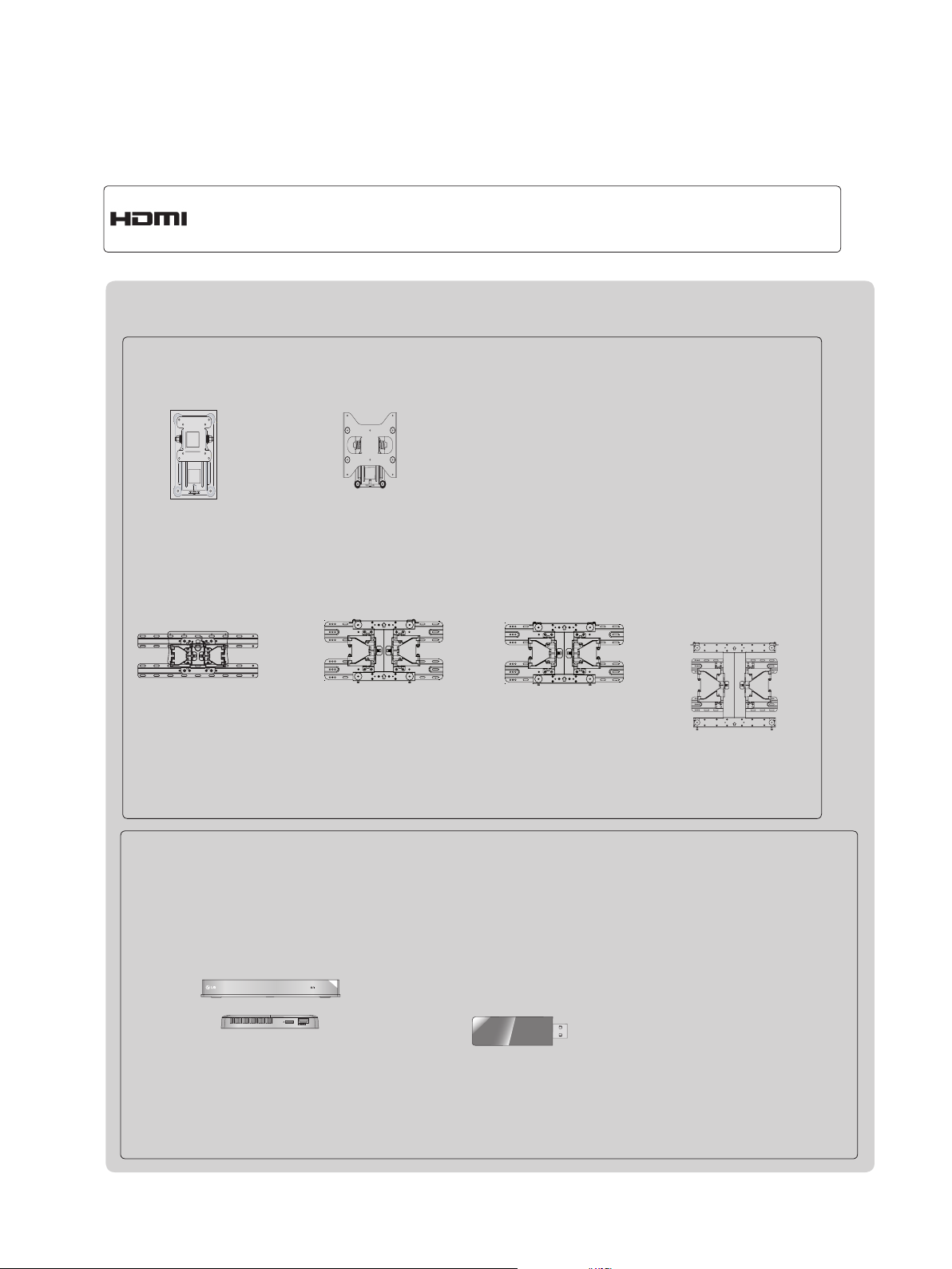
Separate purchase
Wall Mounting Bracket
RW120
(22LD32**)
LSW100B or
LSW100BG
RW230
(26/32LD32**)
LSW200B or
LSW200BG
LSW200BX or
LSW200BXG
LSW400B or
LSW400BG or
DSW400B or
DSW400BG
(22/26/32LD35*, 32LD32**,
32LD4**, 32LD5**, 32LD6**,
22/26/32LE5
32LE7
***, 22/26LE6***,
32LE4***, 26/32LE3***
***,
(37/42/47LD4**, 37/42LD32**,
42/46LD5**, 37/42/47LD6**,
37/42/47LE5
42/47LE8
)
37/42/47LE7
***,
***, 42/47LE4***,
42/47LX6***
)
*** ,
(47LX9***)
(52/60LD5**, 55LD6**,
55LE5
55LE7
***,
55LE8
55LX6***, 55LX9***
***,
***, 55LE4***,
)
Optional extras can be changed or modified for quality improvement without any notification.
Contact your dealer for buying these items.
This device only works with compatible LG LED LCD TV or LCD TV.
Wireless Media Box
(AN-WL100W)
AV1 AV2
HDMI1 HDMI2
HDMI3
COM1 COM2 RGB WIRELESS
(Only 32/42/46/52/60LD5**,
32/37/42/47/55LD6**,
32/37/42/47/55LE53**,
32/37/42/47/55LE55**,
32/37/42/47/55LE7***, 42/47/55LE8***,
32/42LE45**, 42/47/55LX6***,
47/55LX9***, 32LE3***)
HDMI4
WIRELESS
OUT
CONTROL
Wireless LAN for
Broadband/
DLNA Adaptor
(AN-WF100)
(Only 32/42/52LD56*,
32/37/42/47/55LD6**,
32/37/42/47/55LE55**,
32/37/42/47/55LE7***,
42/47/55LE8***, 42/47/55LX6***,
47/55LX9***)
Page 3

CONTENTS
PREPARATION
Accessories .....................................................A-1
Front Panel Controls ....................................... A-4
Back Panel Information ................................. A-11
Stand Installation ...........................................A-20
Woofer Installation :
When Using the Wall Mount ......................... A-26
Not Using the Desk-Type Stand ................... A-27
Back Cover for Wire Arrangement ................A-28
Attaching the TV to a Desk ...........................A-29
TM
How to use dual lock
How to secure the power cable ....................A-30
Swivel Stand .................................................A-30
Positioning your Display ................................ A-30
Connection of TV ..........................................A-31
Kensington Security System .........................A-31
Careful Installation Advice .............................A-32
Desktop Pedestal Installation ........................ A-32
Wall Mount: Horizontal Installation ................ A-33
Remote Control Key Functions .....................A-34
EXTERNAL EQUIPMENT SETUP
Antenna Connection ............................................1
Connecting with a Component Cable .................2
Connecting with an HDMI Cable.........................3
Connecting with an HDMI to DVI Cable .............4
Connecting with an RCA Cable ..........................5
Connecting with an RF Cable .............................6
Headphone Setup ...............................................6
Digital Audio Out Setup .......................................7
Speaker output setup ..........................................7
Connecting with a D-sub 15 Pin Cable ...............8
Usb Setup ...........................................................8
External Equipment Wireless Connection ..........9
Supported Display Resolution ...........................10
Screen Setup for PC mode ...............................12
Network Setup ...................................................16
WATCHING TV / PROGRAMME CONTROL
.............................. A-30
Programme Edit ...............................................34
Software Update ...............................................38
Picture/Sound Test ............................................42
Signal Test .........................................................43
Product/Service Information ..............................44
Network Test ......................................................45
Simple Manual ..................................................46
Selecting the Programme List ...........................47
Input List ............................................................49
Input Label ........................................................50
Data Service ......................................................51
SIMPLINK ..........................................................52
AV Mode ............................................................55
Initializing(Reset to original factory settings) ....56
NETCAST
Legal Notice ......................................................57
Netcast Menu ....................................................59
Movie Online .....................................................60
Weather info ......................................................62
Photo Album ......................................................63
TO USE THE BLUETOOTH
Bluetooth? ........................................................64
Setting the Bluetooth .........................................65
Bluetooth headset ............................................66
Remove the Bluetooth device ...........................69
My Bluetooth Information ..................................70
Receiving photos from external
Bluetooth device ................................................71
Listening to the Musics from external Bluetooth
device ................................................................71
3D IMAGING
3D Technology ..................................................72
Viewing 3D Imaging ..........................................72
When using 3D Glasses ...................................73
3D Imaging viewing range ................................73
Watching 3D Imaging ........................................74
CONTENTS
Turning on the TV .............................................26
Initializing Setup ...............................................26
Programme Selection ........................................26
Volume Adjustment ...........................................26
Quick Menu .......................................................27
On Screen Menus Selection and Adjustment ...28
Auto Programme Tuning ...................................30
Manual Programme Tuning ...............................31
TO USE A USB DEVICE
When connecting a USB device .......................76
DLNA .................................................................78
Movie list ...........................................................82
Photo list ............................................................93
Music list ..........................................................100
Extra Contents ................................................107
I
Page 4

CONTENTS
CONTENTS
DivX Registration Code ...................................108
Deactivation .....................................................109
GAME
Game ...............................................................110
EPG(ELECTRONIC PROGRAMME
GUIDE)(IN DIGITAL MODE)
Switch on/off EPG ...........................................111
Select a programme ........................................112
Button Function in NOW/NEXT Guide Mode .112
Button Function in 8 Day Guide Mode ...........113
Button Function in Date Change Mode ..........113
Button Function in Extended Description Box 114
Button Function in Remind Setting Mode .......114
Button Function in Schedule List Mode ..........114
MHEG (MULTIMEDIA AND
HYPERMEDIA INFORMATION CODING
EXPERT GROUP)(IN DIGITAL MODE)
Teletext within Digital Service .........................115
Teletext in Digital Service ................................115
Switch on MHEG ............................................116
Select a Programme .......................................116
Button Function in Listing Mode .....................117
Button Function in NOW/NEXT Mode ............117
PICTURE CONTROL
Clear Voice II ...................................................136
Preset Sound Settings-Sound Mode ..............137
Sound Setting Adjustment -User Mode ..........138
Infinite Sound ..................................................138
Balance ...........................................................139
TV Speakers On/ Off Setup ............................140
DTV Audio Setting (in digital mode only) ........141
Selecting Digital Audio out ..............................142
Audio Reset .....................................................143
I/II
Stereo/Dual Reception
(In Analogue Mode Only) ................................144
NICAM Reception (In Analogue Mode Only) ..145
Speaker Sound Output Selection ...................145
On-Screen Menu Language
/ Country Selection ..........................................146
Language Selection (In digital mode only) .....147
TIME SETTING
Clock Setup .....................................................149
Auto on/off time setting ...................................150
Sleep Timer setting .........................................151
Alarm Setting ...................................................151
PARENTAL CONTROL / RATINGS
Set Password & Lock System.........................152
Block Programme ............................................153
Parental Control (In Digital Mode only) ...........154
External Input Blocking ...................................155
Key Lock..........................................................156
Picture Size (Aspect Ratio) Control ................118
Picture Wizard .................................................120
Energy Saving .................................................121
Preset Picture Settings ...................................122
Manual Picture Adjustment .............................123
Picture Improvement Technology ....................125
Expert Picture Control .....................................126
Picture Reset ...................................................129
Trumotion ........................................................130
LED Local Dimming ........................................131
Power Indicator ...............................................132
Mode Setting ...................................................133
Demo Mode .....................................................134
SOUND & LANGUAGE CONTROL
Auto Volume Leveler .......................................135
TELETEXT
Switch on/off ...................................................157
SIMPLE Text....................................................157
TOP Text..........................................................158
FASTEXT ........................................................158
Special Teletext Functions ..............................159
APPENDIX
Troubleshooting ...............................................160
Maintenance ....................................................162
Product Specifications .....................................163
IR Codes .........................................................176
External Control Device Setup ........................177
Open Source Software Notice ........................184
II
Page 5
PREPARATION
ACCESSORIES
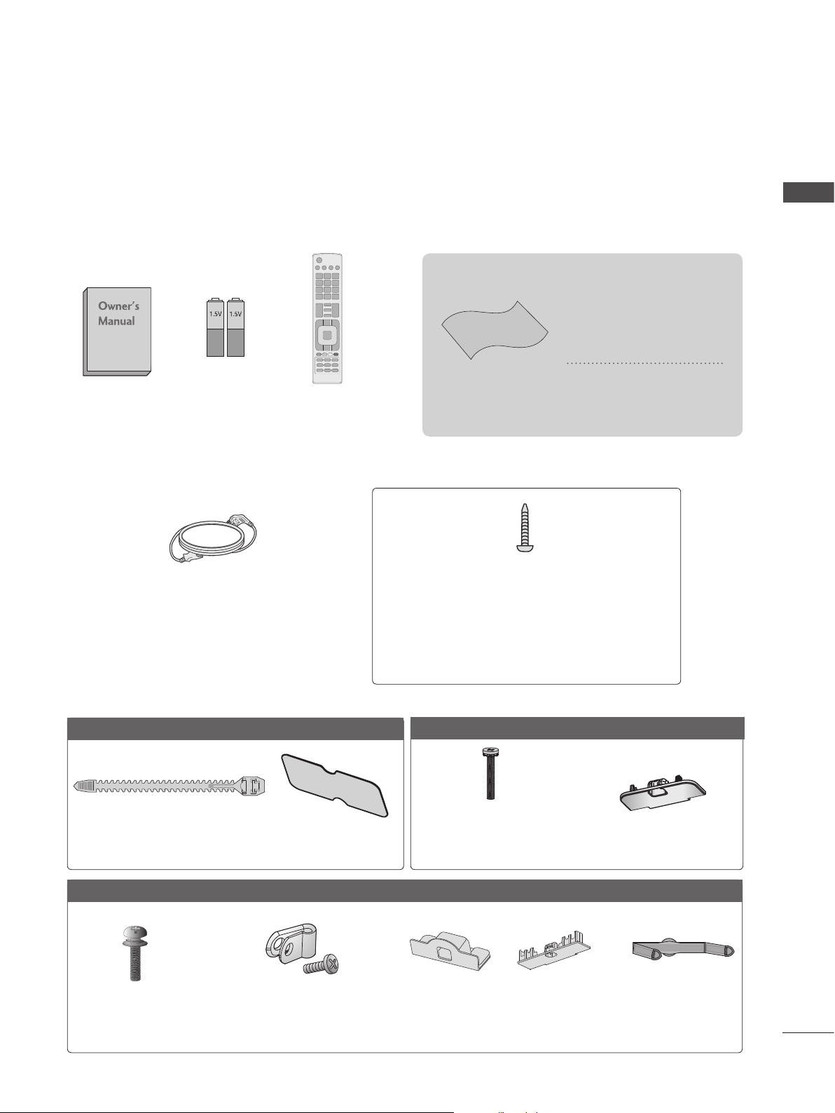
Ensure that the following accessories are included with your TV. If an accessory is missing, please
contact the dealer where you purchased the TV.
■ Image shown may differ from your TV.
This item is not included for all models.
* Lightly wipe any stains
or fingerprints on the
surface of the TV with
the polishing cloth.
PREPARATION
Batteries
Owner’s Manual
(Except for 32/37/42/47/55LE5***,
32/37/42/47/55LE7***, 42/47/55LE8***,
42/47/55LX6***, 47/55LX9***,
32/42/47/55LE4***, 32LE3***)
Only 22LD35*
(AAA)
Power Cord
Remote Control
Polishing Cloth
Polishing cloth for
use on the screen.
1-screw for stand fixing
(Refer to p. A-29)
(Only 26/32LD35*, 26/32/37/42LD32**,
32/37/42LD4**, 32/42LD5**,
32/37/42LD6**, 32LE45**,
32/42/47/55LE46**, 32LE5***, 32LE7***,
32LE3***)
Only 26/32LD35*
x 8
Do not use excessive
force. This may cause
scratching or discolouration.
Cable Tie
(Refer to p. A-28)
Only 22/26/32/37/42LD32**
(Except 22LD32**)
x 4
(M4 x 24)
Bolts for stand
assembly
(Refer to p. A-21)
Protctive bracket and Bolt
Protection Cover
(Refer to p. A-27)
(Except 22LD32**)
for Power Cord
(Refer to p. A-30)
(M4 X 20)
Bolts for stand assembly
(Refer to p. A-20)
or
Protection Cover
(Refer to p. A-27)
Protection Cover
(Refer to p. A-27)
(Only 22LD32**)
Cable manage-
ment clip
(Refer to p. A-28)
A-1
Page 6
PREPARATION
PREPARATION
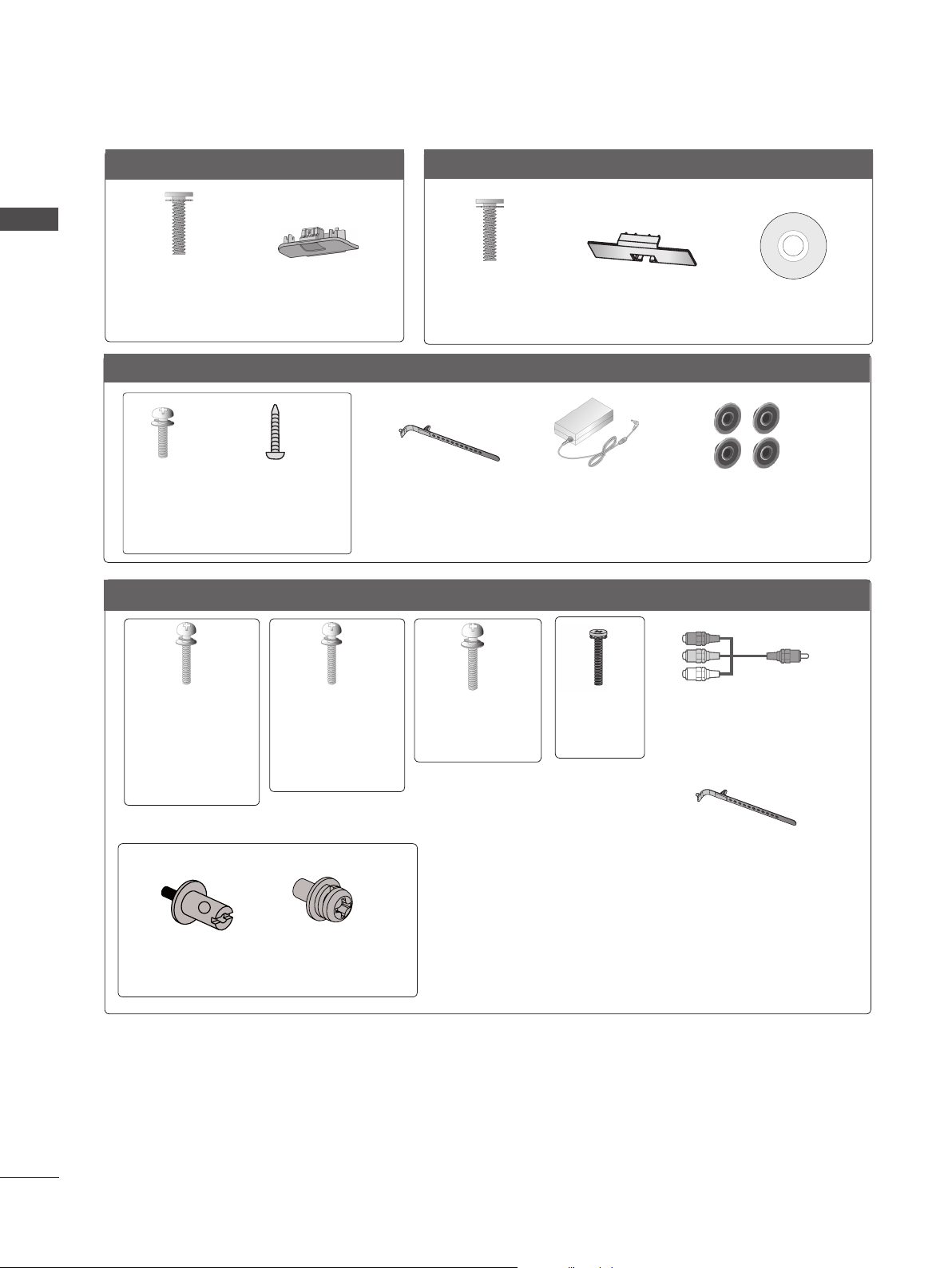
Only 32/37/42/47LD4**
x 8
(M4 X 20)
Bolts for stand
assembly
(Refer to p. A-20)
Only 22/26LE53**, 26LE3***
x 4
(M4x14)
Bolts for stand assembly
Only 32/37/42/47/55LE53**, 32/42/47/55LE4***, 32LE3***
(Only 26LE53
(Refer to p. A-22)
Protection Cover
(Refer to p. A-27)
x 4
(M4x20)
**,
26LE3***
)
Only 32/42/46/52/60LD5**
x 8
(M4 X 20)
Bolts for stand
assembly
(Refer to p. A-20)
Cable Holder
(Refer to p. A-29)
Protection Cover
(Refer to p. A-27)
AC/DC Adaptor
(Refer to p.
A-31)
(Only 32/42/52LD56*)
Nero MediaHome
4 Essentials CD
4-Ring spacers
(Only 26LE53
26LE3***
(Refer to p. A-31)
**,
)
x 4
(M4x22)
(Only 32LE53**,
32LE45**,
32/42/47/
55LE46**,
32LE3***)
Bolts for stand assembly (Refer to p. A-22 or A-25)
(Only 32/42/47/55LE46**)
x 2
Woofer Pemnut
(Refer to p. A-26)
x 4
(M4x24)
(Only
37/42LE53**,
42LE45**)
x 2
Woofer Fixing
Screw
(Refer to p. A-26)
x 4
(M4x26)
(Only
47/55LE53**)
x 4
(M4x16)
x 2
Component gender cable,
AV gender cable
Cable Holder
(Refer to p. A-29)
A-2
Page 7
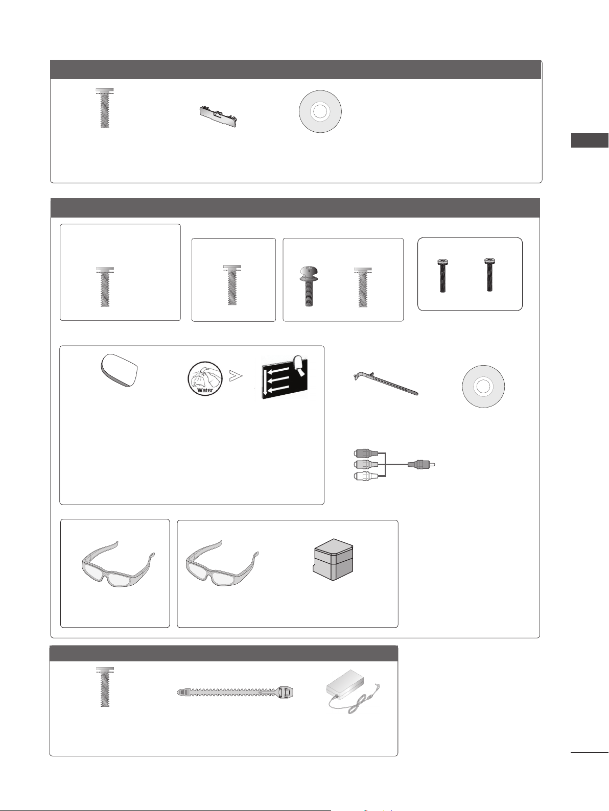
Only 32/37/42/47/55LD6**
x 8
(M4x20)
Bolts for stand assembly
(Refer to p. A-20)
Protection cover
(Refer to p. A-27)
Nero MediaHome
4 Essentials CD
Only 32/37/42/47/55LE55**, 32/37/42/47/55LE7***, 42/47/55LE8***, 42/47/55LX6***, 47/55LX9***
(Only 32/37/42/47LE55**,
32/37/42/47LE7
42/47LX6***)
x 8
***,
(Only 42/47/55LE8
x 8
***
)
(Only 55LE55**,
55LE7
***,
55LX6***)
(Only 47/55LX9***)
x 4
x 4
x 4x 4
PREPARATION
(M4 x 16)
Bolts for stand assembly
(M4 x 20)
(Refer to p. A-23)
cleansing cloths(mitt)
(Only 32/37/42/47/55LE7
***
)
Slightly wipe stained spot on the exterior only with
the cleansing cloths(mitt) for the product exterior if
there is stain or fingerprint on surface of the exterior.
For cleaning front frame, please slowly wipe in one
direction after spraying water 1~2 times on cleansing
cloths. Please remove excessive moisture after cleaning.
Excessive moisture may cause water stains on the frame.
(Only 42/47/55LX6
***
)
(Only 47/55LX9***)
x 2
3D Glasses
(AG-S1**)
3D Glasses
(AG-S1**)
Stand Rear Cover
(M4 x 16)(M4 x 24)
M4x12
Bolts for stand assembly
(Refer to p. A-24)
Cable Holder
(Refer to p. A-29)
Nero MediaHome
4 Essentials CD
x 2
Component gender cable,
AV gender cable
M4x22
Only 22/26LE6***
x 2
(M4x16)
Bolts for stand assembly
(Refer to p. A-24)
Cable Tie
(Refer to p. A-28)
AC/DC Adaptor
(Refer to p.
A-31)
A-3
Page 8
PREPARATION
P
INPUT
MENU
OK
P
INPUT
MENU
OK
P
INPUT
MENU
OK
P
P
OK
MENU
INPUT
P
INPUT
MENU
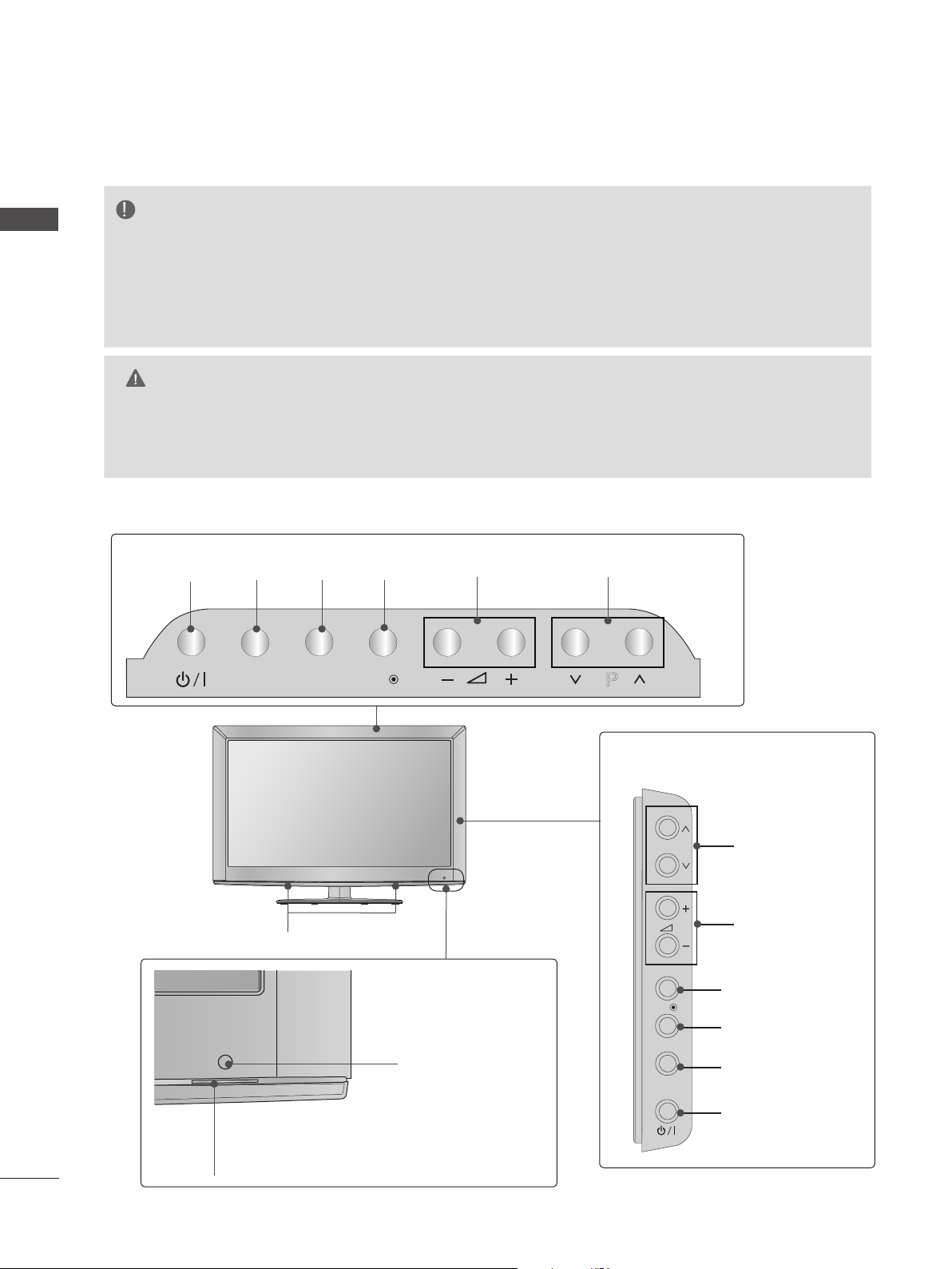
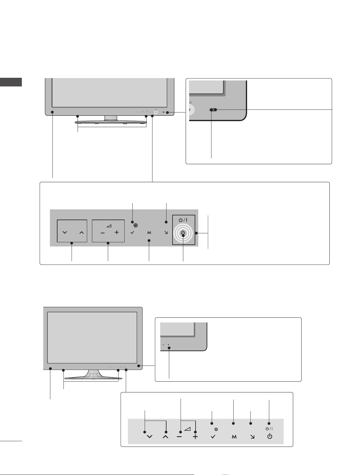
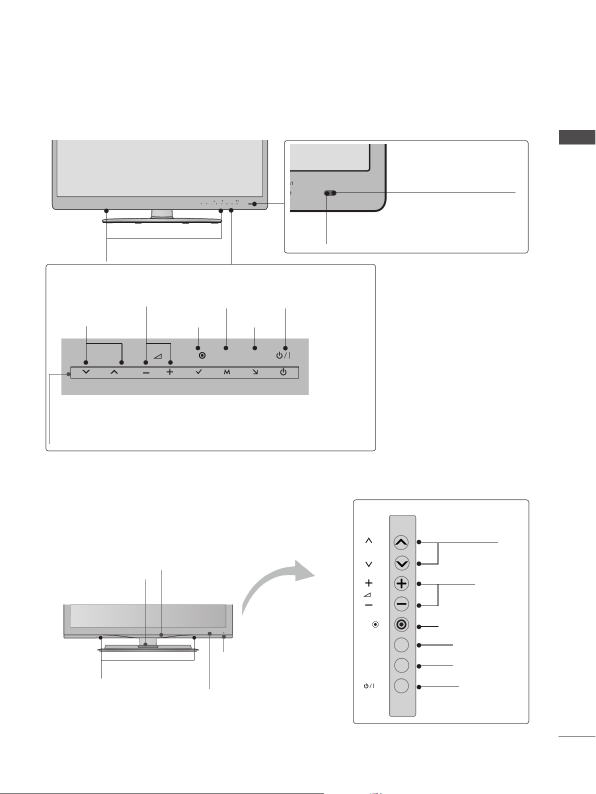
FRONT PANEL CONTROLS
NOTE
PREPARATION
►
TV can be placed in standby mode in order to reduce the power consumption. And TV should
be switched off using the power switch on the TV if it will not be watched for some time, as this
will reduce energy consumption.
► The energy consumed during use can be significantly reduced if the level of brightness of the picture
is reduced, and this will reduce the overall running cost.
CAUTION
► Do not step on the glass stand or subject it to any impact. It may break, causing possible injury from fragments
of glass, or the TV may fall.
► Do not drag the TV. The floor or the product may be damaged.
■ Image shown may differ from your TV.
Only 22/26/32LD35*
Only 22LD35*
INPUTPOWER
INPUT
MENU
OKMENU
OK
PROGRAMMEVOLUME
P
Only 26/32LD35*
A-4
P
PROGRAMME
SPEAKER
VOLUME
Remote Control Sensor
OK
MENU
INPUT
Power/Standby Indicator
(Can be adjusted using the Power
Indicator in the OPTION menu.)
OK
MENU
INPUT
POWER
Page 9
MENU
OK
P
INPUT
MENU
OK
P
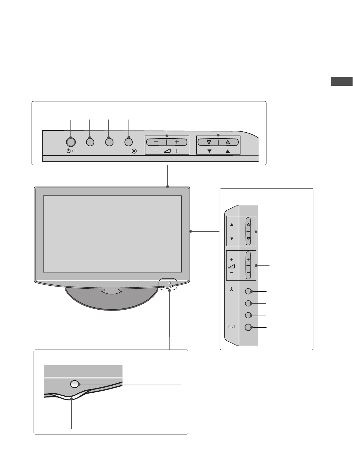
■ Image shown may differ from your TV.
Only 22/26/32/37/42LD32**
Only 22/26LD32**
PREPARATION
INPUTPOWER
INPUT MENUPOK
OKMENU
VOLUME
PROGRAMME
Only 32/37/42LD32**
OK
P
PROGRAMME
VOLUME
OK
Remote Control Sensor
Power/Standby Indicator
(Can be adjusted using the Power
Indicator in the OPTION menu.)
MENU
INPUT
MENU
INPUT
POWER
A-5
Page 10
PREPARATION
P
OK
P
OK
P
MENU
INPUT
OK
P
MENU
INPUT
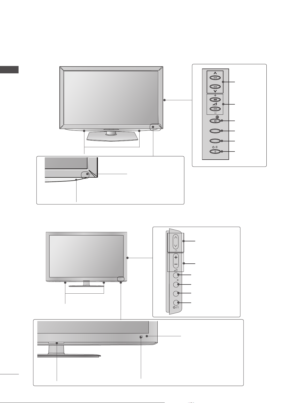
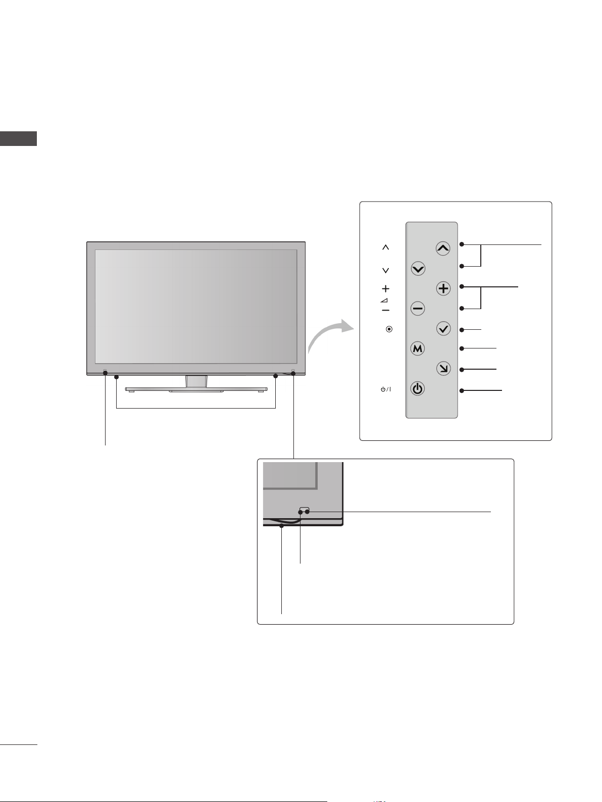
■ Image shown may differ from your TV.
Only 32/37/42/47LD4**
PREPARATION
P
PROGRAMME
VOLUME
SPEAKER
Power/Standby Indicator
(Can be adjusted using the Power
Indicator in the OPTION menu.)
Only 32/42/46/52/60LD5**
Remote Control Sensor
OK
MENU
INPUT
PROGRAMME
P
VOLUME
OK
MENU
INPUT
POWER
A-6
SPEAKER
Power/Standby Indicator
(Can be adjusted using the Power
Indicator in the OPTION menu.)
OK
MENU
INPUT
Intelligent Sensor
Adjusts picture according to
OK
MENU
INPUT
POWER
Remote Control Sensor
the surrounding conditions.
Page 11
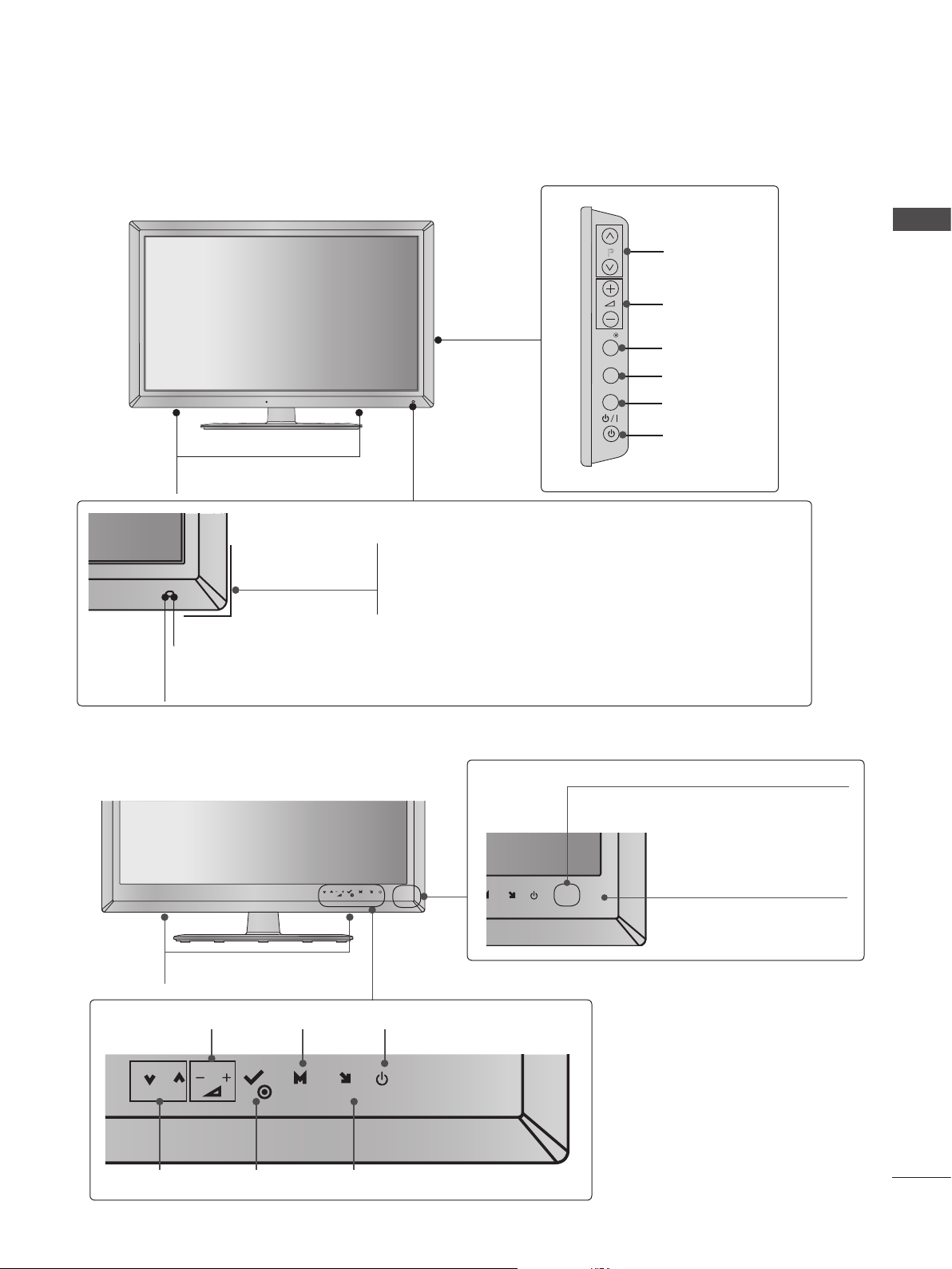
■ Image shown may differ from your TV.
INPUT
MENU
OK
P
INPUT
MENU
OK
P
Only 32/37/42/47/55LD6**
SPEAKER
Power/Standby Indicator
(Can be adjusted using the Power Indicator in the
OPTION menu.)
Remote Control Sensor
Intelligent Sensor
Adjusts picture according to the surrounding conditions.
P
OK
MENU
INPUT
PROGRAMME
VOLUME
OK
MENU
INPUT
POWER
PREPARATION
■ Image shown may differ from your TV.
Only 22/26LE53**, 26LE3***
P
OK
SPEAKER
VOLUME MENU POWER
P
OK
MENU
INPUT
OKPROGRAMME
INPUT
Power/Standby Indicator
(Can be adjusted using the
Power Indicator in the
OPTION menu.)
MENU
INPUT
U
INPUT
Remote Control Sensor
A-7
Page 12
PREPARATION
■ Image shown may differ from your TV.
Only 32/37/42/47/55LE5***, 32/37/42/47/55LE7***, 42/47/55LX6***, 32LE3***
PREPARATION
SPEAKER
P
MENU
OK
INPUT
Intelligent Sensor
Adjusts picture according to
the surrounding conditions.
Emitter (Only 42/47/55LX6
***
)
It is the part equipped with the emitter
exchanging signal with 3D glasses.
Please be careful not to block
the screen with objects or people
while watching a 3D Video.
Touch Sensor
• You can use the desired button function by touching.
INPUTOK
P
PROGRAMME
VOLUME
OK
MENU
MENU
INPUT
Only 22/26LE6***
Remote Control Sensor
Power/Standby Indicator
(Can be adjusted using the Power
Indicator in the OPTION menu.)
POWER
A-8
SPEAKER
Remote Control Sensor
Power/Standby Indicator
(Can be adjusted using the Power
Indicator in the OPTION menu.)
PROGRAMME
VOLUME
MENU
INPUTOK
OKP MENU INPUT
POWER
Page 13
■ Image shown may differ from your TV.
Only 42/47/55LE8***
MENU
P
OK
INPUT
SPEAKER
Touch Sensor
• You can use the desired button function by touching.
PREPARATION
Intelligent Sensor
Adjusts picture according to
the surrounding conditions.
Remote Control Sensor
PROGRAMME
P
VOLUME
OK
OK
MENU
MENU
POWER
INPUT
INPUT
Power/Standby Indicator
(Can be adjusted using the Power Indicator in the OPTION
menu.)
Only 32/42/47/55LE4***
Power/Standby Indicator
(Can be adjusted using the Power
Indicator in the OPTION menu.)
Woofer
(Only 32/42/47/55LE46**)
P
PROGRAMME
VOLUME
SPEAKER
Intelligent Sensor
Adjusts picture according to
the surrounding conditions.
Remote Control Sensor
OK
MENU
INPUT
OK
MENU
INPUT
POWER
A-9
Page 14
PREPARATION
■ Image shown may differ from your TV.
PREPARATION
Only 47/55LX9***
SPEAKER
Emitter
It is the part equipped with the
emitter exchanging signal with 3D
glasses.
Please be careful not to block
the screen with objects or
people while watching a 3D
Video.
P
OK
MENU
INPUT
Intelligent Sensor
Adjusts picture according to
the surrounding conditions.
Remote Control Sensor
PROGRAMME
VOLUME
OK
MENU
INPUT
POWER
A-10
Power/Standby Indicator
(Can be adjusted using the Power Indicator
in the OPTION menu.)
Page 15
K
AC-IN
H/P
SERVICE ONLY
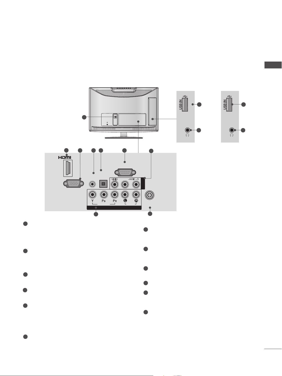
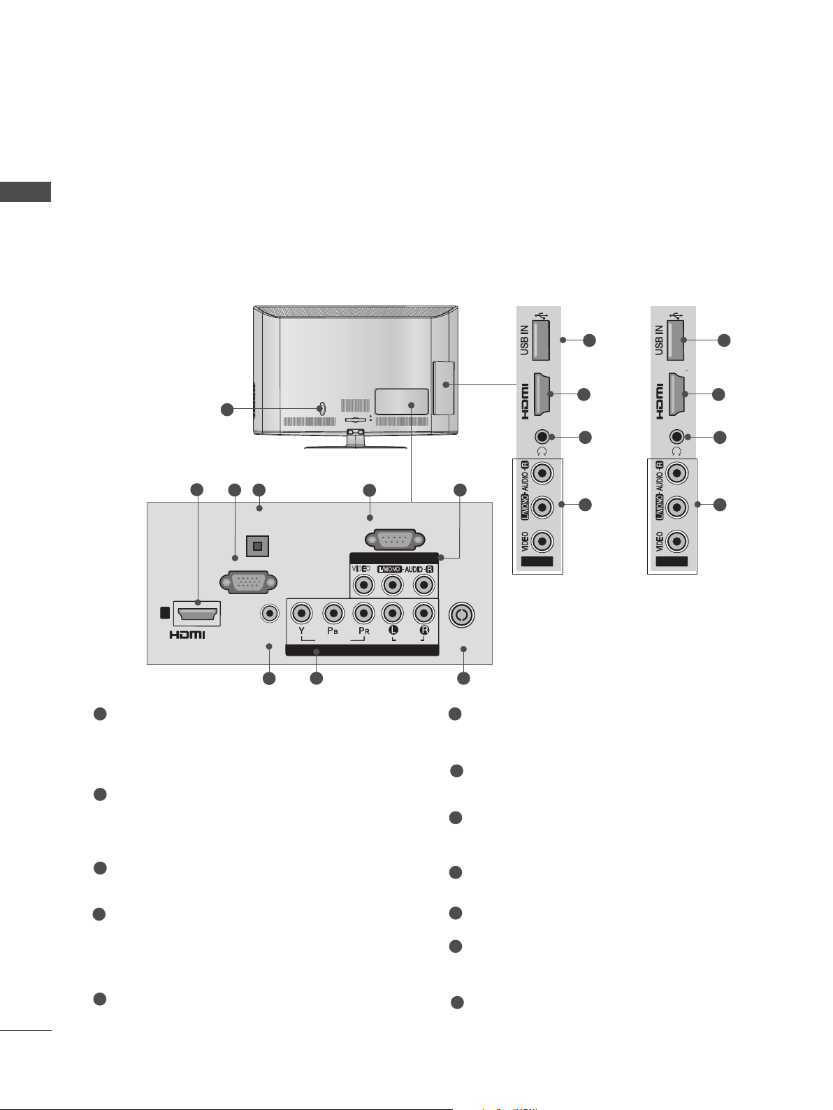
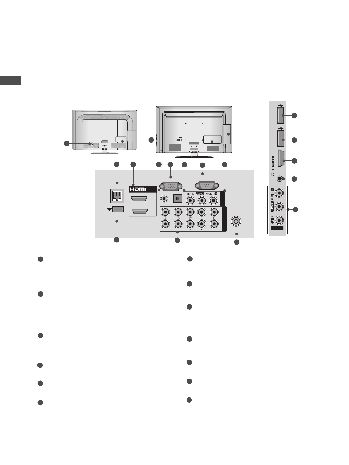
BACK PANEL INFORMATION
SERVICE ONLY
■ Image shown may differ from your TV.
Only 22LD35*
PREPARATION
1
2
3 4 5 6
/DVI IN
AUDIO IN
(RGB/DVI)
RGB IN
(PC)
8
(CONTROL & SERVICE)
OPTICAL
DIGITAL
AUDIO OUT
VIDEO
VIDEO
COMPONENT IN
RS-232C IN
L(MONO)
AUDIO
AUDIO
R
AV IN
ANTENNA /
CABEL IN
Only 22LD350
SERVICE ONLY
H/P
7
9
Only 22LD352C
10
11
12
SERVICE ONLY
11
H/P
1
Power Cord Socket
This TV operates on an AC power. The voltage is indicated on the Specifications page.
(► p.163 to 175) Never attempt to operate
the TV on DC power.
2
HDMI/DVI IN Input
Connect an HDMI signal to HDMI IN. Or DVI
(VIDEO) signal to HDMI/DVI port with DVI to
HDMI cable.
3
RGB IN Input
Connect the output from a PC.
4
RGB/DVI Audio Input
Connect the audio from a PC or DTV.
5
OPTICAL DIGITAL AUDIO OUT
Connect digital audio to various types of
equipment.
Connect to a Digital Audio Component.
Use an Optical audio cable.
RS-232C IN (CONTROL & SERVICE) PORT
6
7
Audio/Video Input
Connect audio/video output from an external
device to these jacks.
8
Component Input
Connect a component video/audio device to
these jacks.
Antenna / Cable Input
9
Connect antenna or cable to this jack.
10
SERVICE ONLY PORT
Headphone Socket
11
Plug the headphone into the headphone
socket.
12
USB Input
Connect USB storage device to this jack.
Connect to the RS-232C port on a PC.
This port is used for Service or Hotel mode.
A-11
Page 16
PREPARATION
H/P
AV IN2
IN 2
SERVICE ONLY
SERVICE ONLY
■ Image shown may differ from your TV.
PREPARATION
Only 26/32LD35*
Only 26/32LD350
SERVICE ONLY
IN 2
1
2
3 4
OPTICAL
DIGITAL
AUDIO OUT
RGB IN
(PC)
AC IN
CABLE MANAGEMENT
5
RS-232C IN
(CONTROL & SERVICE)
AV IN 1
VIDEO
L/MONO
H/P
6
AV IN2
Only 26/32LD352C
10
IN 2
2
11
6
H/P
AV IN2
12
SERVICE ONLY
2
11
6
1
/DVI IN
AUDIO IN
(RGB/DVI)
7
VIDEO
COMPONENT IN
8
AUDIO
ANTENNA /
CABLE IN
9
A-12
1
Power Cord Socket
This TV operates on an AC power. The voltage is indicated on the Specifications page.
(► p.163 to 175) Never attempt to operate
the TV on DC power.
2
HDMI/DVI IN Input
Connect an HDMI signal to HDMI IN. Or DVI
(VIDEO) signal to HDMI/DVI port with DVI to
HDMI cable.
3
RGB IN Input
Connect the output from a PC.
4
OPTICAL DIGITAL AUDIO OUT
Connect digital audio to various types of
equipment.
Connect to a Digital Audio Component.
Use an Optical audio cable.
5
RS-232C IN (CONTROL & SERVICE) PORT
Connect to the RS-232C port on a PC.
This port is used for Service or Hotel mode.
6
Audio/Video Input
Connect audio/video output from an external
device to these jacks.
7
RGB/DVI Audio Input
Connect the audio from a PC or DTV.
8
Component Input
Connect a component video/audio device to
these jacks.
9
Antenna / Cable Input
Connect antenna or cable to this jack.
10
SERVICE ONLY PORT
Headphone Socket
11
Plug the headphone into the headphone
socket.
12
USB Input
Connect USB storage device to this jack.
Page 17
■ Image shown may differ from your TV.
INPUT
MENU
OK
P
Only 22/26/32/37/42LD32**
1
Only 22LD32**
Only 26/32/37/
42LD32**
11
PREPARATION
Only 22LD32**
2 3 4
11
5 6 7
1
Power Cord Socket
This TV operates on an AC power. The voltage is indicated on the Specifications page.
(► p.163 to 175) Never attempt to operate
the TV on DC power.
2
RGB/DVI Audio Input
Connect the audio from a PC or DTV.
3
OPTICAL DIGITAL AUDIO OUT
Connect digital audio to various types of
equipment.
Connect to a Digital Audio Component.
Use an Optical audio cable.
8
9 10
12
Only 26/32/37/42LD32**
2 3 4
5 7 8 9 10
6
RGB IN Input
Connect the output from a PC.
7
RS-232C IN (CONTROL & SERVICE) PORT
Connect to the RS-232C port on a PC.
This port is used for Service or Hotel mode.
8
Component Input
Connect a component video/audio device to
these jacks.
9
SPEAKER OUTPUT (STEREO)
The phone socket for external speaker and
control port is on this jack
12
4
Audio/Video Input (AV IN)
Connect audio/video output from an external
device to these jacks.
5
HDMI/DVI IN Input
Connect an HDMI signal to HDMI IN. Or DVI
(VIDEO) signal to HDMI/DVI port with DVI to
HDMI cable.
10
Antenna / Cable Input
Connect antenna or cable to this jack.
11
USB Input
Connect USB storage device to this jack.
12
Headphone Socket
Plug the headphone into the headphone
socket.
A-13
Page 18
PREPARATION
R
AUDIO
HDMI IN 2 USB IN
H/P
■ Image shown may differ from your TV.
PREPARATION
Only 32/37/42/47LD4**
10
1
2
3 4
8
7
1
Power Cord Socket
This TV operates on an AC power. The voltage is indicated on the Specifications page.
(► p.163 to 175) Never attempt to operate
the TV on DC power.
2
HDMI/DVI IN Input
Connect an HDMI signal to HDMI IN. Or DVI
(VIDEO) signal to HDMI/DVI port with DVI to
HDMI cable.
3
RGB IN Input
Connect the output from a PC.
4
OPTICAL DIGITAL AUDIO OUT
Connect digital audio to various types of
equipment.
Connect to a Digital Audio Component.
Use an Optical audio cable.
5
RS-232C IN (CONTROL & SERVICE) PORT
Connect to the RS-232C port on a PC.
This port is used for Service or Hotel mode.
2
11
5
6
9
6
Audio/Video Input
6
Connect audio/video output from an external
device to these jacks.
7
RGB/DVI Audio Input
Connect the audio from a PC or DTV.
8
Component Input
Connect a component video/audio device to
these jacks.
9
Antenna / Cable Input
Connect antenna or cable to this jack.
10
USB Input
Connect USB storage device to this jack.
11
Headphone Socket
Plug the headphone into the headphone
socket.
A-14
Page 19
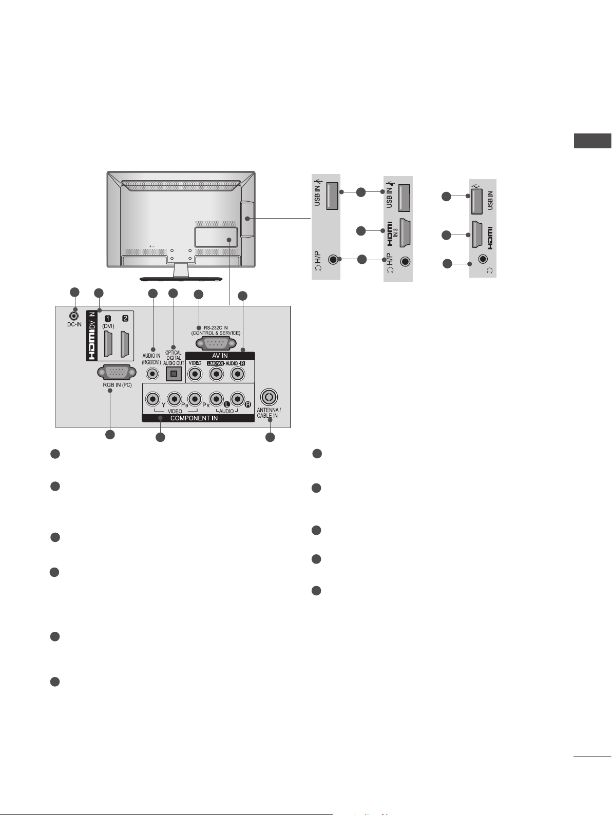
■ Image shown may differ from your TV.
IN 3
H/P
Only 32/42/46/52/60LD55*
PREPARATION
11
AC IN
VIDEO
9
2
2
1
1
Power Cord Socket
/DVI IN
1
3 4 5 6
OPTICAL
DIGITAL
AUDIO OUT
RGB IN
(PC)
WIRELESS
CONTROL
AUDIO IN
(RGB/DVI)
This TV operates on an AC power. The voltage is indicated on the Specifications page.
(► p.163 to 175) Never attempt to operate
the TV on DC power.
2
HDMI/DVI IN Input
Connect an HDMI signal to HDMI IN. Or DVI
(VIDEO) signal to HDMI/DVI port with DVI to
HDMI cable.
3
WIRELESS Control
Connect the Wireless Dongle to the TV to
control the external input devices connected
to Media Box wirelessly.
4
RGB IN Input
Connect the output from a PC.
CABLE MANAGEMENT
(CONTROL & SERVICE)
AV IN1
L/MONO
VIDEO
COMPONENT IN
COMPONENT IN
IN 3
7
8
RS-232C IN
R
AUDIO
2
1
AUDIO
7
ANTENNA /
CABLE IN
10
RS-232C IN (CONTROL & SERVICE) PORT
H/P
AV IN2
2
12
8
Connect to the RS-232C port on a PC.
This port is used for Service or Hotel mode.
8
Audio/Video Input
Connect audio/video output from an external
device to these jacks.
9
Component Input
Connect a component video/audio device to
these jacks.
10
Antenna / Cable Input
Connect antenna or cable to this jack.
11
USB Input
Connect USB storage device to this jack.
5
OPTICAL DIGITAL AUDIO OUT
Connect digital audio to various types of
equipment.
Connect to a Digital Audio Component.
Use an Optical audio cable.
6
RGB/DVI Audio Input
Connect the audio from a PC or DTV.
12
Headphone Socket
Plug the headphone into the headphone
socket.
A-15
Page 20
PREPARATION
HDMI IN 3 USB IN 1
USB IN 2
h}GpuY
puGZ
H/P
USB IN 1
USB IN 2
■ Image shown may differ from your TV.
PREPARATION
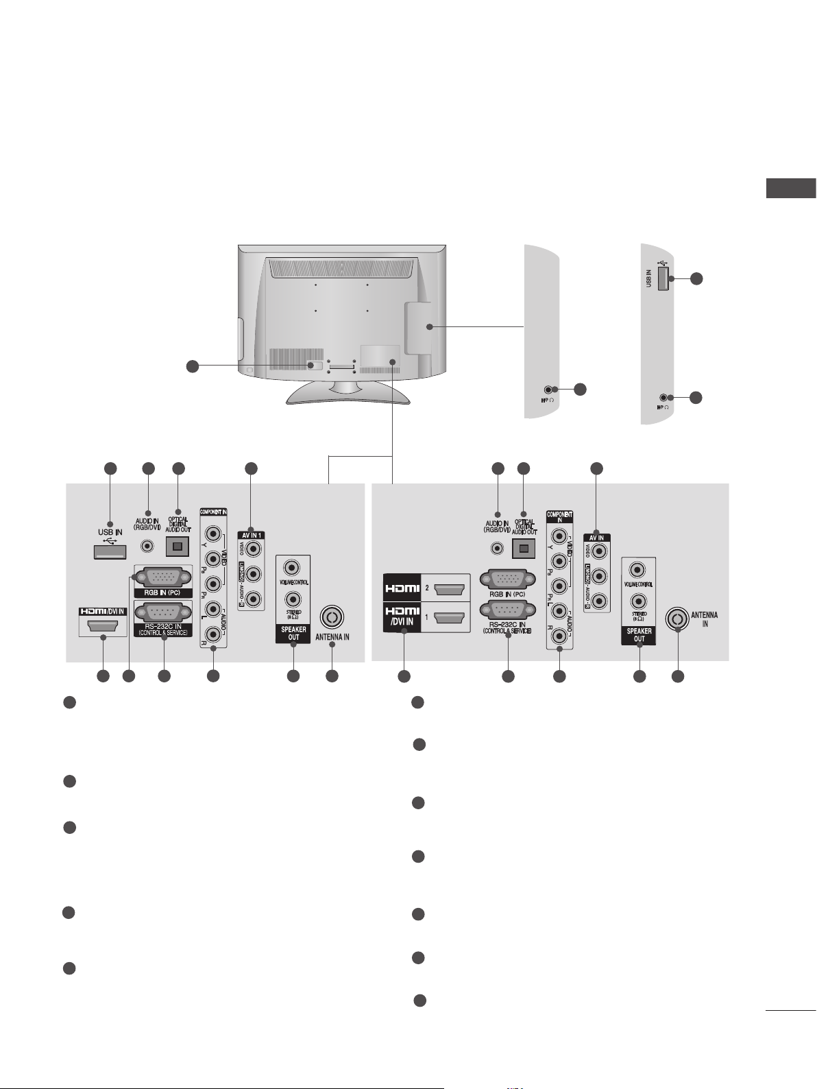
Only 32/42/52LD56*, 32/37/42/47/55LD6**
or
1
AC IN
CABLE MANAGEMENT
2
3 54
LAN
WIRELESS
CONTROL
9
1
/DVI IN
2
1
RGB IN
RGB/DVI
AUDIO IN
AC IN
(PC)
OPTICAL DIGITAL
AUDIO OUT
VIDEO
10
CABLE MANAGEMENT
6
(CONTROL & SERVICE)
L(MONO)
VIDEO
7
RS-232C IN
AUDIO
AUDIO
USB IN 2
puGZ
8
H/P
AV IN 1
R
COMPONENT IN
2
1
ANTENNA /
CABLE IN
11
h}GpuY
12
12
USB IN 1
3
13
8
1
Power Cord Socket
This TV operates on an AC power. The voltage is indicated on the Specifications page.
(► p.163 to 175) Never attempt to operate
the TV on DC power.
2
LAN
Network connection for Weather info, Photo
Album, Movie Online, etc.
Also used for video, photo and music files on
a local network.
3
HDMI/DVI IN Input
Connect an HDMI signal to HDMI IN. Or DVI
(VIDEO) signal to HDMI/DVI port with DVI to
HDMI cable.
4
RGB/DVI Audio Input
Connect the audio from a PC or DTV.
5
RGB IN Input
Connect the output from a PC.
6
OPTICAL DIGITAL AUDIO OUT
Connect digital audio to various types of
equipment.
Connect to a Digital Audio Component.
Use an Optical audio cable.
7
RS-232C IN (CONTROL & SERVICE) PORT
Connect to the RS-232C port on a PC.
This port is used for Service or Hotel mode.
8
Audio/Video Input
Connect audio/video output from an external
device to these jacks.
9
WIRELESS Control
Connect the Wireless Dongle to the TV to
control the external input devices connected
to Media Box wirelessly.
10
Component Input
Connect a component video/audio device to
these jacks.
11
Antenna / Cable Input
Connect antenna or cable to this jack.
12
USB Input
Connect USB storage device to this jack.
13
Headphone Socket
Plug the headphone into the headphone
socket.
A-16
Page 21
■ Image shown may differ from your TV.
Only 22/26LE53**, 22/26LE6***, 26LE3***
1
2
7
1
DC ADAPTER PORT
Connect to the power cord socket.
4
3
8
5
6
Only 22LE53**
9
10
2
11
Only 26LE53**,
26LE3***
7
RGB IN Input
Connect the output from a PC.
10
IN 3
2
11
H/P
Only 22/26LE6***
PREPARATION
2
HDMI/DVI IN Input
Connect an HDMI signal to HDMI IN. Or DVI
(VIDEO) signal to HDMI/DVI port with DVI to
HDMI cable.
3
RGB/DVI Audio Input
Connect the audio from a PC or DTV.
4
OPTICAL DIGITAL AUDIO OUT
Connect digital audio to various types of
equipment.
Connect to a Digital Audio Component.
Use an Optical audio cable.
5
RS-232C IN (CONTROL & SERVICE) PORT
Connect to the RS-232C port on a PC.
This port is used for Service or Hotel mode.
6
Audio/Video Input
Connect audio/video output from an external
device to these jacks.
8
Component Input
Connect a component video/audio device to
these jacks.
9
Antenna / Cable Input
Connect antenna or cable to this jack.
10
USB Input
Connect USB storage device to this jack.
11
Headphone Socket
Plug the headphone into the headphone
socket.
A-17
Page 22
PREPARATION
H/P
USB IN
/ AUDIO
IN 4
Y P
B
P
R
USB IN 2
USB IN 1
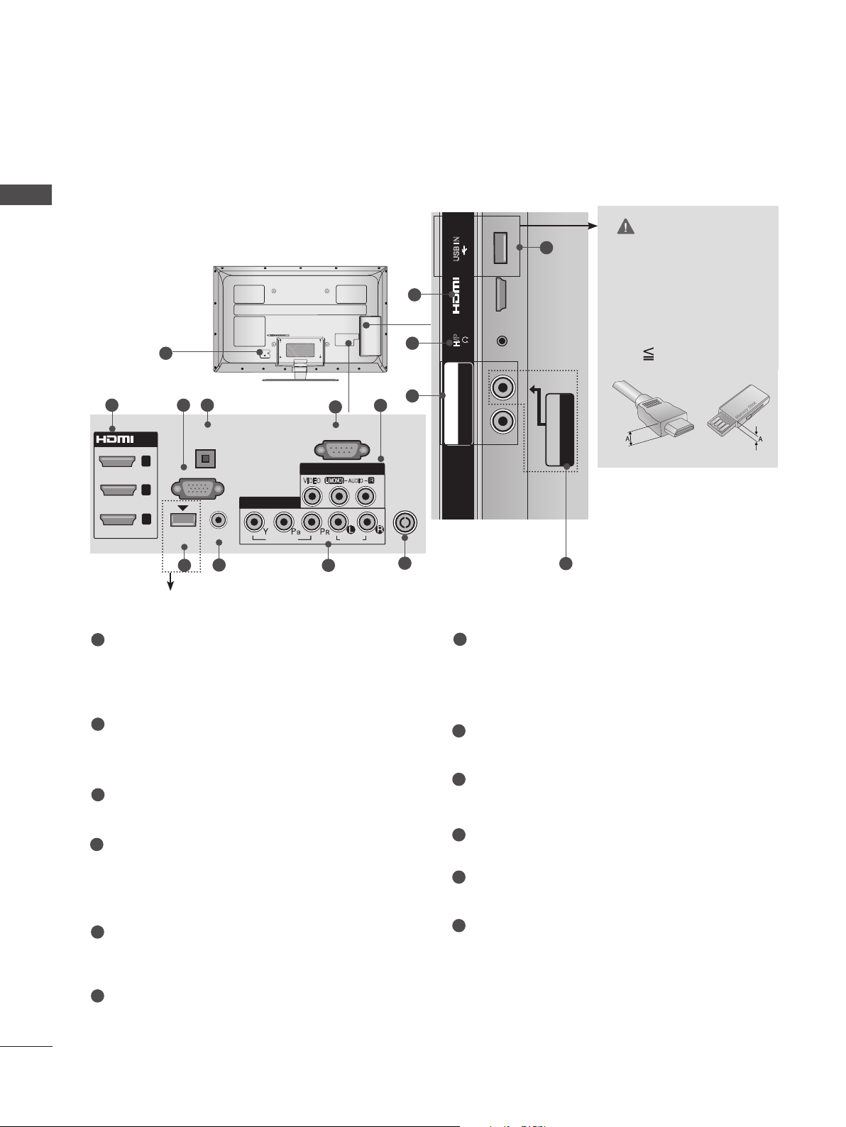
■ Image shown may differ from your TV.
PREPARATION
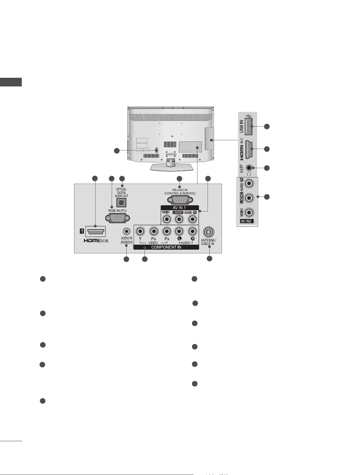
Only 32/37/42/47/55LE53**,
32/42/47/55LE4***, 32LE3***
1
2 43
OPTICAL
/DVI IN
3
2
1
(DVI)
DIGITAL
AUDIO OUT
RGB IN
(PC)
COMPONENT IN1
AUDIO IN
WIRELESS
(RGB/DVI)
CONTROL
8
7 9
Except 32/42/47/55LE46**
VIDEO
5
RS-232C IN
(CONTROL & SERVICE)
AV IN 1
L(MONO)
VIDEO
AUDIO
AUDIO
R
6
12
9
ANTENNA /
CABLE IN
10
CAUTION
USB IN
11
► Use a product with the
following thickness for
2
IN 4
optimal connection to
HDMI cable(only HDMI
H/P
IN 4) / USB device.
*A 10 mm
/ AUDIO
R
P
B
Y P
COMPONENT IN2
AV IN2
VIDEO / AUDIO
6
1
Power Cord Socket
This TV operates on an AC power. The voltage is indicated on the Specifications page.
(► p.163 to 175) Never attempt to operate
the TV on DC power.
HDMI/DVI IN Input
2
Connect an HDMI signal to HDMI IN. Or DVI
(VIDEO) signal to HDMI/DVI port with DVI to
HDMI cable.
3
RGB IN Input
Connect the output from a PC.
OPTICAL DIGITAL AUDIO OUT
4
Connect digital audio to various types of
equipment.
Connect to a Digital Audio Component.
Use an Optical audio cable.
5
RS-232C IN (CONTROL & SERVICE) PORT
Connect to the RS-232C port on a PC.
This port is used for Service or Hotel mode.
6
Audio/Video Input
Connect audio/video output from an external
device to these jacks.
7
WIRELESS Control
(Except 32/42/47/55LE46**)
Connect the Wireless Dongle to the TV to
control the external input devices connected
to Media Box wirelessly.
8
RGB/DVI Audio Input
Connect the audio from a PC or DTV.
Component Input
9
Connect a component video/audio device to
these jacks.
10
Antenna / Cable Input
Connect antenna or cable to this jack.
11
USB Input
Connect USB storage device to this jack.
Headphone Socket
12
Plug the headphone into the headphone
socket.
A-18
Page 23
USB IN 2
USB IN 1
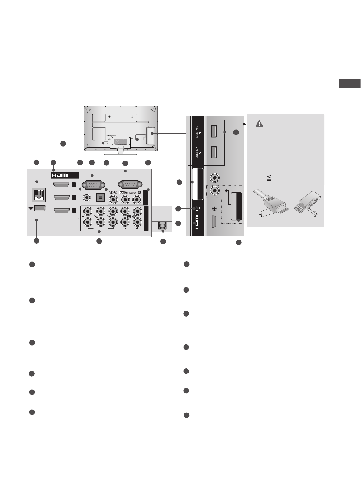
■ Image shown may differ from your TV.
USB IN 2
USB IN 1
COMPONENT IN3
AUDIO / Y P
B
P
R
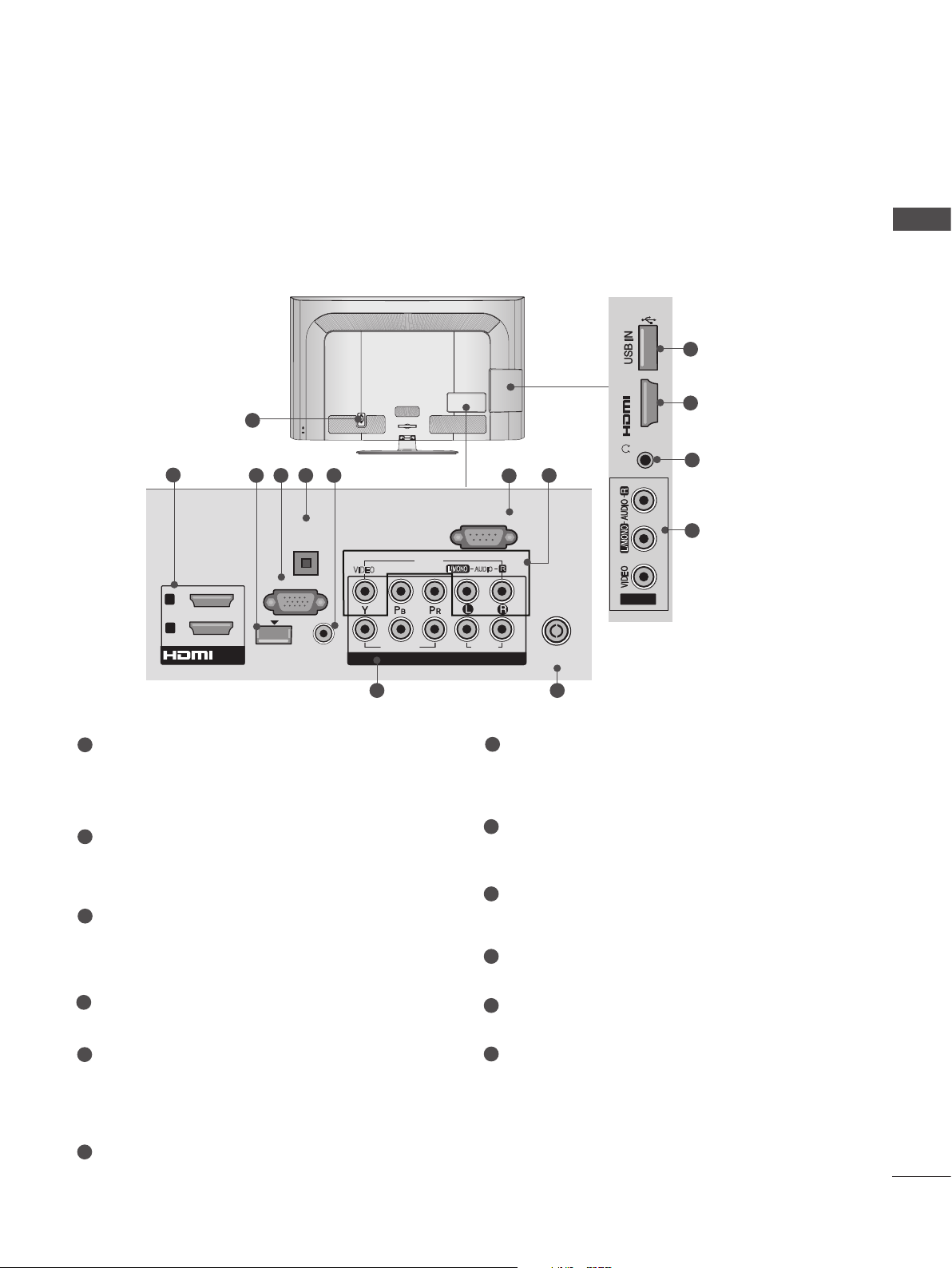
Only 32/37/42/47/55LE55**, 32/37/42/47/55LE7***, 42/47/55LE8***,
42/47/55LX6***, 47/55LX9***
USB IN 2
1
2
LAN
WIRELESS
CONTROL
9
3 54
/DVI IN
3
2
1
RGB IN
(RGB/DVI)
AUDIO IN
2
1
(PC)
OPTICAL DIGITAL
AUDIO OUT
VIDEO
10
6
(CONTROL & SERVICE)
L(MONO)
VIDEO
7
RS-232C IN
AUDIO
AUDIO
R
8
AV IN 1
COMPONENT IN
ANTENNA/
CABLE IN
13
10
12
3
USB IN 1
B PR
COMPONENT IN3
AUDIO / Y P
H/P
IN 4
PREPARATION
CAUTION
11
► Use a product with the
following thickness for
optimal connection to
HDMI cable(only HDMI
IN 4) / USB device.
*A 10 mm
AV IN2
VIDEO / AUDIO
8
1
Power Cord Socket
This TV operates on an AC power. The voltage is indicated on the Specifications page.
(► p.163 to 175) Never attempt to operate
the TV on DC power.
2
LAN
Network connection for Weather info, Photo
Album, Movie Online, etc.
Also used for video, photo and music files on
a local network.
3
HDMI/DVI IN Input
Connect an HDMI signal to HDMI IN. Or DVI
(VIDEO) signal to HDMI/DVI port with DVI to
HDMI cable.
4
RGB/DVI Audio Input
Connect the audio from a PC or DTV.
5
RGB IN Input
Connect the output from a PC.
6
OPTICAL DIGITAL AUDIO OUT
Connect digital audio to various types of
equipment.
Connect to a Digital Audio Component.
Use an Optical audio cable.
7
RS-232C IN (CONTROL & SERVICE) PORT
Connect to the RS-232C port on a PC.
This port is used for Service or Hotel mode.
8
Audio/Video Input
Connect audio/video output from an external
device to these jacks.
9
WIRELESS Control
Connect the Wireless Dongle to the TV to
control the external input devices connected
to Media Box wirelessly.
10
Component Input
Connect a component video/audio device to
these jacks.
11
USB Input
Connect USB storage device to this jack.
12
Headphone Socket
Plug the headphone into the headphone
socket.
13
Antenna / Cable Input
Connect antenna or cable to this jack.
A-19
Page 24
PREPARATION
M4X20
M4X20
M4X20
M4X20
M4X20
STAND INSTALLATION
■ Image shown may differ from your TV.
PREPARATION
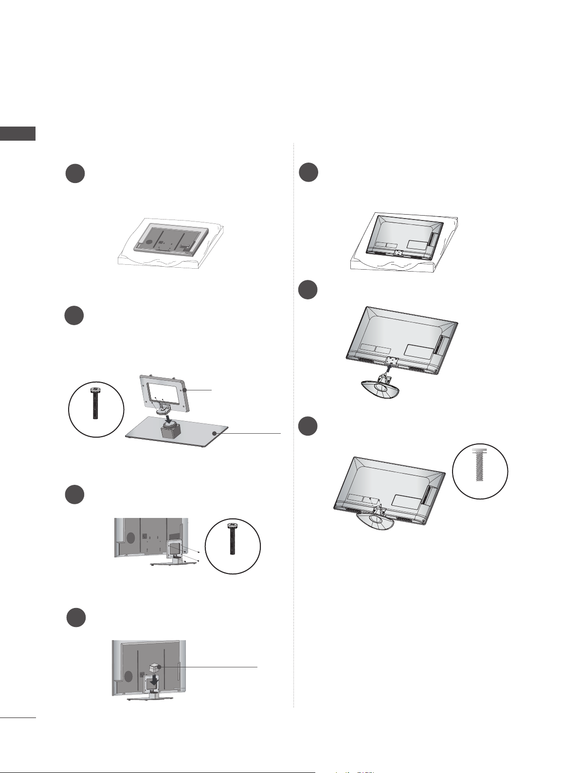
When assembling the desk type stand, check whether the bolt is fully tightened. (If not tightened fully,
the product can tilt forward after the product installation.) If you tighten the bolt with excessive force,
the bolt can deviate from abrasion of the tightening part of the bolt.
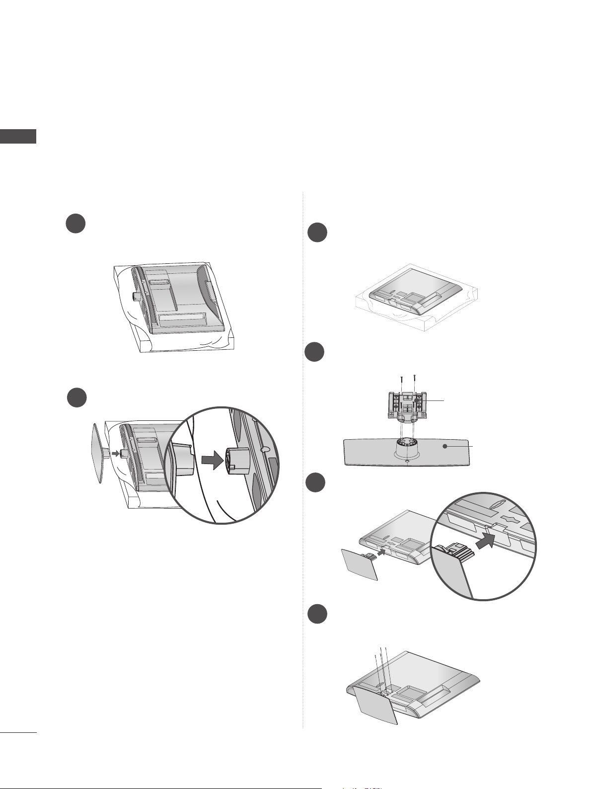
Only 22LD35*
Carefully place the TV screen side down
1
on a cushioned surface to protect the
screen from damage.
Assemble the TV as shown.
2
Only 26/32LD35*, 32/37/42/47LD4**,
32/42/46/52/60LD5**, 32/37/42/47/55LD6**
Carefully place the TV screen side down
1
on a cushioned surface to protect the
screen from damage.
Assemble the parts of the Stand Body with
2
the Stand Base of the TV.
Stand Body
Stand Base
Assemble the TV as shown.
3
A-20
Fix the 4 bolts securely using the holes in
4
the back of the TV.
Page 25
■ Image shown may differ from your TV.
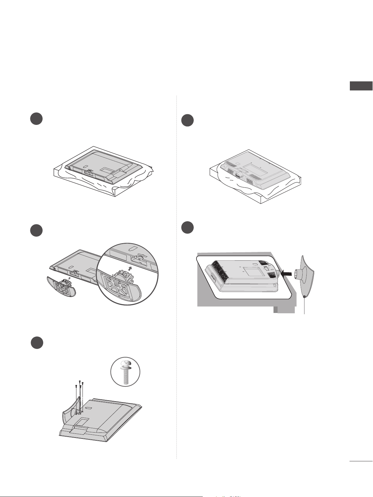
Only 26/32/37/42LD32**
Carefully place the TV screen side down
1
on a cushioned surface to protect the
screen from damage.
Assemble the TV as shown.
2
Only 22LD32**
Carefully place the TV screen side down
1
on a cushioned surface to protect the
screen from damage.
Assemble the TV as shown.
2
PREPARATION
Fix the 4 bolts securely using the holes in
3
the back of the TV.
M4 X 14
Stand Base
A-21
Page 26
PREPARATION
PREPARATION
■ Image shown may differ from your TV.
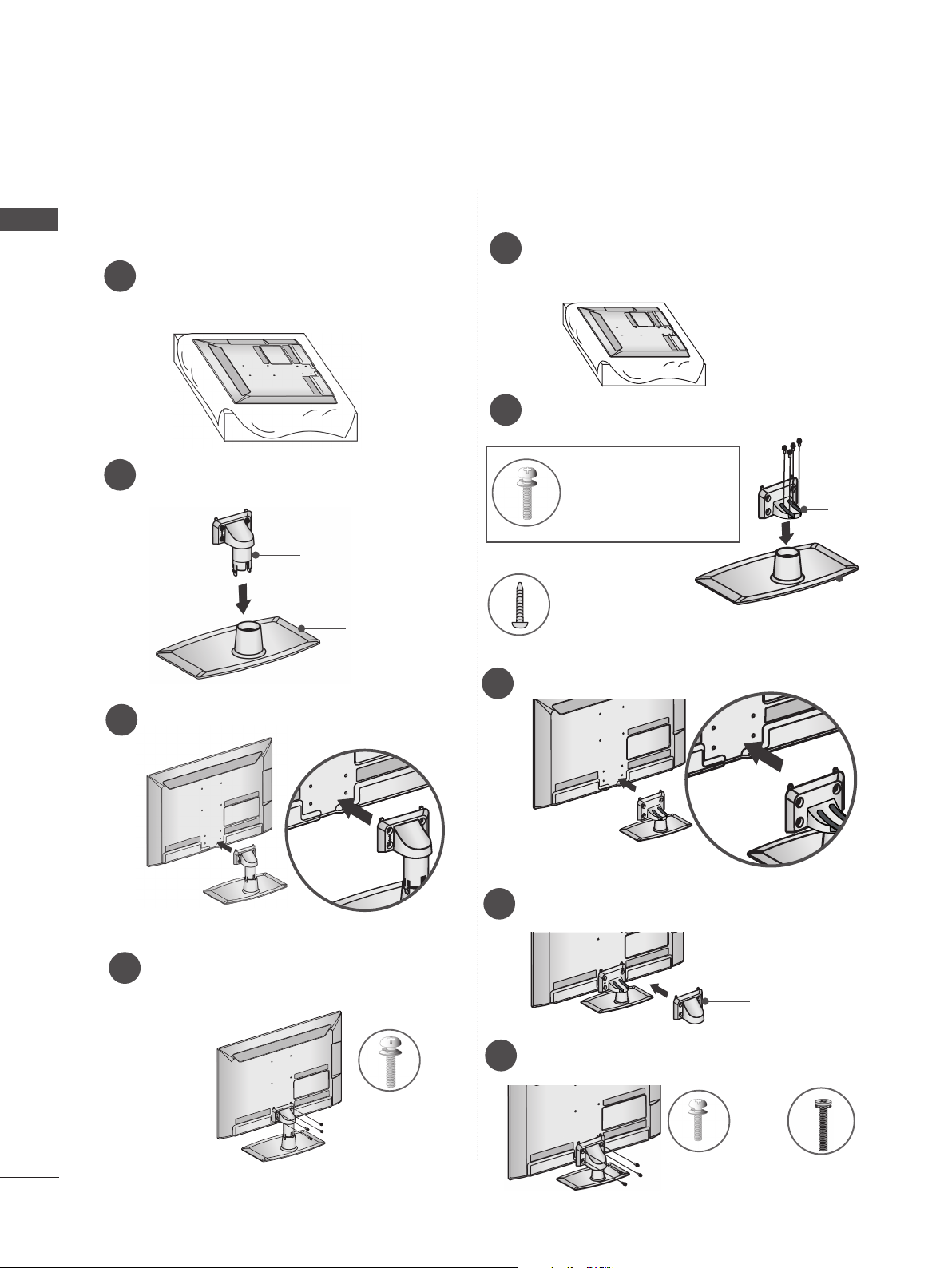
Only 22LE53**
Carefully place the TV screen side down
1
on a cushioned surface to protect the
screen from damage.
Assemble the parts of the Stand Body with
2
the Stand Base of the TV.
Stand Body
Stand Base
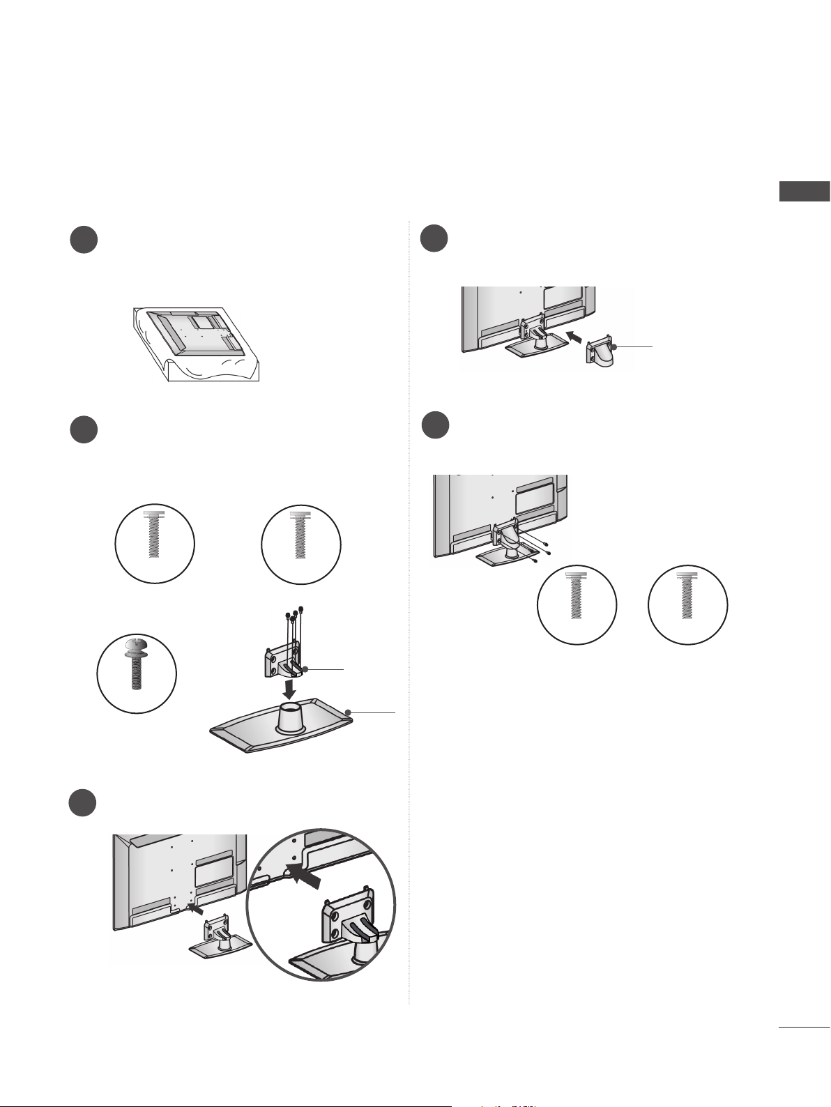
Only 26/32/37/42/47/55LE53**, 26/32LE3***
Carefully place the TV screen side down
1
on a cushioned surface to protect the
screen from damage.
Assemble the parts of the Stand Body with
2
the Stand Base of the TV.
M4 X 22(Only 32LE53**,
32LE3***)
M4 X 24 (Only 37/42LE53**)
M4 X 26 (Only 47/55LE53**)
M4 X 20
(Only 26LE53**, 26LE3***)
Stand
Body
Stand
Base
Assemble the TV as shown.
3
Fix the 4 bolts securely using the holes in
4
the back of the TV.
M4 X 14
Assemble the TV as shown.
3
Assemble the parts of the Stand Rear
4
Cover with the TV.
Fix the 4 bolts securely using the holes in
5
the back of the TV.
Stand Rear
Cover
A-22
M4 X 14
(Only 26LE53
26LE3***
M4 X 16 (Only
32/37/42/47/55LE53
**,
)
32LE3***
**,
)
Page 27
■ Image shown may differ from your TV.
Only 32/37/42/47/55LE55**, 32/37/42/47/55LE7***, 42/47/55LE8***, 42/47/55LX6***
Carefully place the TV screen side down
1
on a cushioned surface to protect the
screen from damage.
Assemble the parts of the Stand Body with
2
the Stand Base of the TV.
At this time, tighten the screws that hold the
Stand Body on.
M4 X 16
(Only 32/37/42/47LE55**,
32/37/42/47LE7
, 42/47LX6***)
***
M4 X 20
(Only 42/47/55LE8
***
)
Assemble the parts of the Stand Rear
4
Cover with the TV.
Fix the 4 bolts securely using the holes in
5
the back of the TV.
M4 X 16
PREPARATION
Stand Rear
Cover
M4 X 20
M4 X 24
(Only 55LE55**,
55LE7***, 55LX6***)
Assemble the TV as shown.
3
Stand
Body
Stand
Base
(Only
32/37/42/47/55LE55**,
32/37/42/47/55LE7
42/47/55LX6***)
***
(Only 42/47/55LE8
,
***
)
A-23
Page 28
PREPARATION
■ Image shown may differ from your TV.
PREPARATION
Only 47/55LX9***
Carefully place the TV screen side down
1
on a cushioned surface to protect the
screen from damage.
Assemble the parts of the Stand Body with
2
the Stand Base of the TV.
At this time, tighten the screws that hold the
Stand Body on.
Stand Body
M4 X 22
Stand Base
Only 22/26LE6***
Carefully place the TV screen side down
1
on a cushioned surface to protect the
screen from damage.
Assemble the TV as shown.
2
Fix the 2 screws securely using the holes
3
in the back of the TV.
A-24
Fix the 4 bolts securely using the holes in
3
the back of the TV.
M4 X 12
Assemble the parts of the Stand Rear
4
Cover with the TV.
Stand Rear
Cover
M4 X 16
Page 29
■ Image shown may differ from your TV.
Only 32/42/47/55LE4***
Carefully place the TV screen side down
1
on a cushioned surface to protect the
screen from damage.
Assemble the parts of the Stand Rear
4
Cover with the TV.
Stand Rear
Cover
PREPARATION
Assemble the parts of the Stand Body with
2
the Stand Base of the TV.
At this time, tighten the screws that hold the
Stand Body on.
Stand
Body
M4 X 22(Only 32LE45
32/42/47/55LE46**
M4 X 24 (Only 42LE45**)
Stand
Base
Assemble the TV as shown.
3
Fix the 4 bolts securely using the holes in
5
the back of the TV.
M4 X 16
**,
)
A-25
Page 30
PREPARATION
WOOFER INSTALLATION :WHEN USING THE WALL
MOUNT
PREPARATION
Only 32/42/47/55LE46**
Carefully place the TV screen side down
1
on a cushioned surface to protect the
screen from damage.
Remove the screws from the TV.
2
4
Detach the Woofer from the stand.
Assemble the Woofer with the TV.
5
Turn the PEM nut for the woofer using a
flathead driver and install the 2 screws as
shown.
When installing the woofer in the TV,
make sure that the power cord is not
twisted, bent or pinched.
A-26
Detach the Stand Rear Cover and Stand
3
from TV.
Page 31

NOT USING THE DESK-TYPE STAND
■ Image shown may differ from your TV.
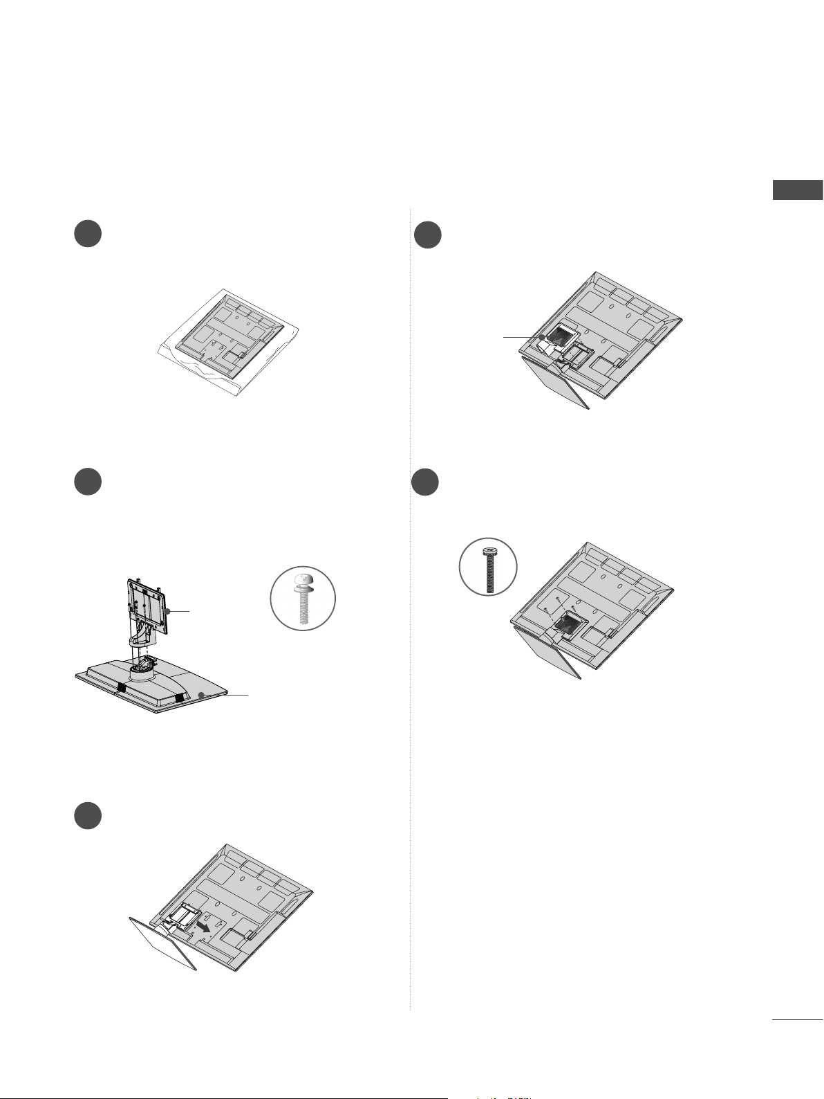
When installing the wall-mounted unit, use the protection cover.
Only 22LD35*
Carefully place the TV screen side down
1
on a cushioned surface to protect the
screen from damage.
Loose the bolts from TV.
2
Detach the Stand from TV.
3
Only 22LD32**
Carefully place the TV screen side down
1
on a cushioned surface to protect the
screen from damage.
Loose the bolts from TV.
2
Detach the Stand from TV.
3
PREPARATION
After removing the protection paper from
4
the protection cover, adhere it to the TV as
shown.
Protection Cover
Only 26/32LD35*, 26/32/37/42LD32**,
32/37/42/47LD4**, 32/42/46/52/60LD5**,
32/37/42/47/55LD6**
Insert the Protection cover into the TV until
clicking sound.
Protection cover
Insert the Protection cover into the TV
4
Protection Cover
Fix the 4 bolts securely using the holes in
5
the back of the TV.
A-27
Page 32

PREPARATION
K
AC-IN
AC IN
AC IN
AC IN
AC IN
BACK COVER FOR WIRE ARRANGEMENT
■ Image shown may differ from your TV.
PREPARATION
Only 22LD35*, 22/26LE6***
After connecting the cables as necessary, install
Cable Tie as shown and bundle the cables.
Only 22LD32**
Connect the cables as necessary.
1
To connect additional equipment, see the
External equipment setup section.
AC-IN
K
Cable Tie
Install the Cable Management Clip as shown.
2
Only 26/32LD35*, 26/32/37/42LD32**,
32/37/42/47LD4**, 32/37/42/47/55LD6**,
32/42/46/52/60LD5**
Connect the cables as necessary.
1
To connect additional equipment, see the
External equipment setup section.
Fit the Cable Management Clip as shown.
3
AC IN
A-28
Open the Cable Management Clip as
2
shown and manage the cables.
AC IN
How to remove the cable management clip (22LD32**)
Hold the Cable
Management Clip
with both hands and pull
Cable Management Clip
Fit the Cable management clip as shown.
3
it backward.
NOTE
►Do not use the CABLE MANAGEMENT CLIP
AC IN
to lift the TV.
- If the TV is dropped, you may be injured or the
TV may be damaged.
Page 33

■ Image shown may differ from your TV.
USB IN 2
USB IN 1
Only 22/26LE5***, 26LE3***
After connecting the cables as necessary,
install Cable Holder as shown and bundle the
cables.
ATTACHING THE TV TO A
DESK
(Only 26/32LD35*,
32/37/42LD4**, 32/42LD5
32LE45**, 32/42/47/55LE46**, 32LE5***,
32LE7***, 32LE3***
■ Image shown may differ from your TV.
The TV must be attached to desk so it cannot be
pulled in a forward/backward direction, potentially causing injury or damaging the product. Use
only an attached screw.
26/32/37/42LD32**
)
AC IN
,
**, 32/37/42LD6**,
PREPARATION
Cable Holder
Only 32/37/42/47/55LE5***,
32/37/42/47/55LE7***, 42/47/55LE8***,
42/47/55LX6***, 47/55LX9***, 32/42/47/55LE4***,
32LE3***
Secure the power cord with the Cable
1
Holder on the TV back cover.
It will help prevent the power cable from
being removed by accident.
Cable Holder
After connecting the cables as necessary,
2
install Cable Holder as shown and bundle
the cables.
CABLE MANAGEMENT
1-Screw ( provided as parts of the product)
Stand
Desk
Cable Holder
WARNING
►To prevent TV from falling over, the TV
should be securely attached to the floor/wall
per installation instructions. Tipping, shaking,
or rocking the machine may cause injury.
A-29
Page 34

PREPARATION
HOW TO USE DUAL LOCK
TM
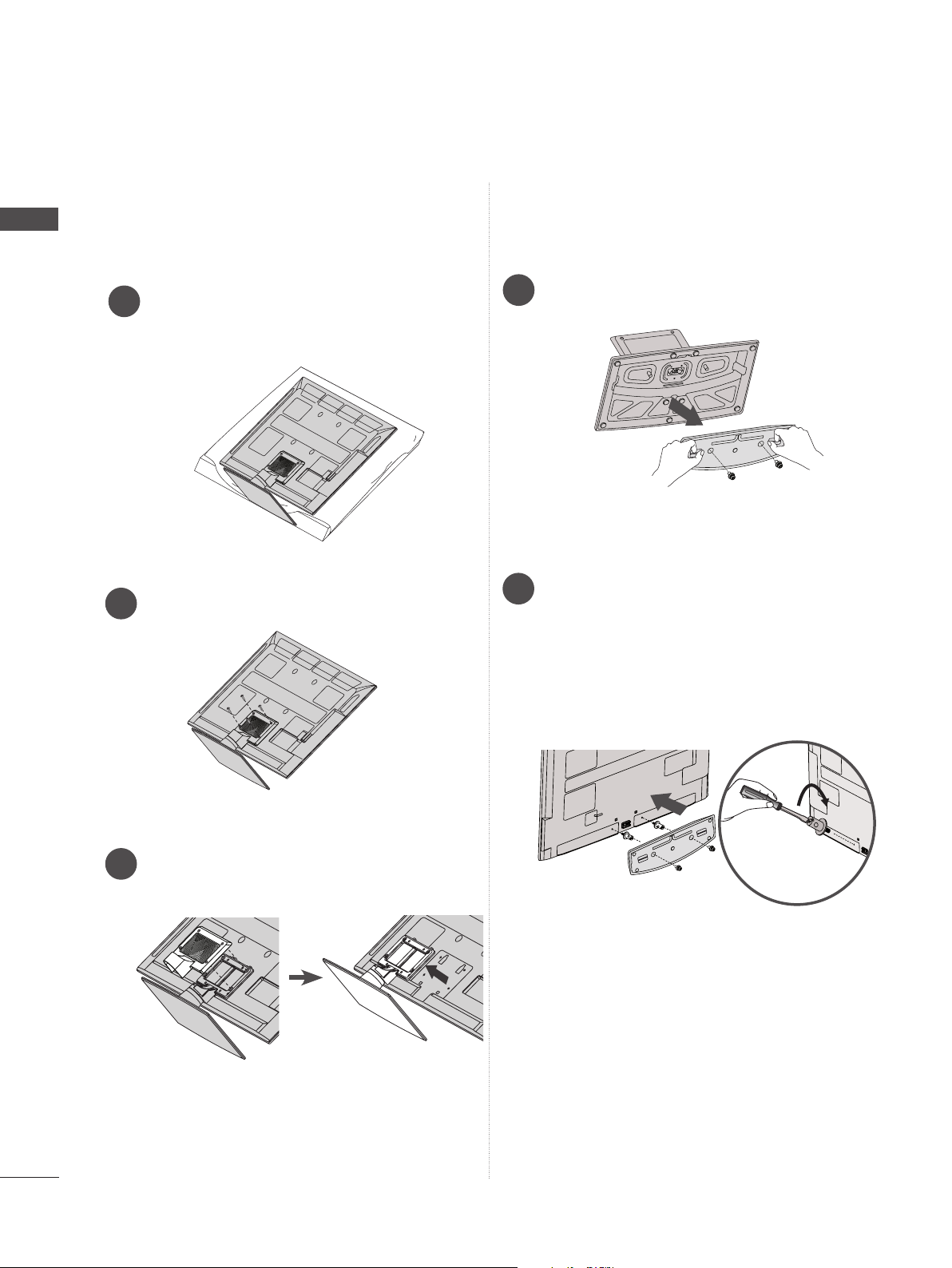
HOW TO SECURE THE
PREPARATION
■ This feature is not available for all models.
Fix the set-top box to the TV and use it when you want to.
After removing the protection paper from
1
the Dual Lock, stick it to the TV and the settop box as shown.
POWER CABLE
(Only
Secure the power cable with the Protective Bracket
and the bolt as shown. It will help prevent the power
cable from being removed by accident.
26/32/37/42LD32**)
Bolt
Protective Bracket
SWIVEL STAND
(Except for 22LD35*, 22LD32**, 22/26LE6***)
■ Image shown may differ from your TV.
After installing the TV, you can adjust the TV set
manually to the left or right direction by 20
degrees to suit your viewing position.
Attach the set-top box to the TV by pressing
2
the Velcro strips together.
POSITIONING YOUR
DISPLAY
(Only 22LD35*, 22LD32**)
■ Image shown may differ from your TV.
Adjust the position of the panel in various ways
for maximum comfort.
• Tilt range
0
12
0
3
A-30
Page 35

CONNECTION OF TV
KENSINGTON SECURITY
(Only 22/26LE5***, 22/26LE6***, 26LE3***)
■ Image shown may differ from your TV.
DC IN
AC/DC Adaptor
Connect the antenna cable to the antenna
1
input port on the TV.
Connect the AC/DC adapter plug to the
2
power input jack on the TV.
Connect the power cord to the AC/DC
3
adapter first, then plug the power cord into
the wall power outlet.
CAUTION
► Please be sure to connect the TV to the DC
power adapter before connecting the TV's
power plug to a wall power outlet.
SYSTEM
■ This feature is not available for all models.
■ Image shown may differ from your TV.
The TV is equipped with a Kensington Security
System connector on the back panel. Connect
the Kensington Security System cable as shown
below.
For the detailed installation and use of the
Kensington Security System, refer to the user’s
guide provided with the Kensington Security
System.
For further information, contact http://www.kensington.com, the internet homepage of the
Kensington
company. Kensington sells security systems for
expensive electronic equipment such as notebook PCs and LCD projectors.
NOTE
Kensington Security System is an
► The
optional accessory.
►If the TV feels cold to the touch, there may
be a small “flicker” when it is turned on.
► Some minute
the screen, appearing as tiny red, green, or
blue spots. However, they have no adverse
effect on the monitor's performance.
► Avoid
finger(s) against it for long periods of time.
Doing so may produce some temporary dis-
tortion effects on the screen.
dot defects may be visible on
touching the LCD screen or holding your
PREPARATION
< Only 26LE5***, 26LE3*** >
■ Image shown may differ from your TV.
4-Ring spacers
Place the ring spacers on the set before
installing the wall mounting bracket so that
the inclination of the backside of the set can
be adjusted perpendicularly.
AC IN
CABLE MANAGEMENT
A-31
Page 36

PREPARATION
PREPARATION
CAREFUL INSTALLATION
ADVICE
■ You should purchase necessary components
to fix the TV safety and secure to the wall on
the market.
■ Position the TV close to the wall to avoid the
possibility of it falling when pushed.
■ The instructions shown below are a safer way
to set up the TV, by fixing it to the wall, avoiding the possibility of it falling forwards if pulled.
This will prevent the TV from falling forward
and causing injury. This will also prevent the
TV from damage. Ensure that children do not
climb or hang from the TV.
1
2
Use the eye-bolts or TV brackets/bolts to fix the
1
product to the wall as shown in the picture.
(If your TV has bolts in the eyebolts, loosen then
bolts.)
* Insert the eye-bolts or TV brackets/bolts and
tighten them securely in the upper holes.
1
2
■ The TV can be installed in various ways such as
on a wall, or on a desktop etc.
■ The TV is designed to be mounted horizontally.
EARTHING
Ensure that you connect the earth wire to prevent
possible electric shock. If grounding methods are
not possible, have a qualified electrician install a
separate circuit breaker.
Do not try to earth the TV by connecting it to telephone wires, lightening rods or gas pipes.
Power
Supply
Circuit
breaker
DESKTOP PEDESTAL
INSTALLATION
For adequate ventilation allow a clearance of 10
cm all around the TV.
10 cm
Secure the wall brackets with the bolts on the
2
wall. Match the height of the bracket that is
mounted on the wall.
3
Use a sturdy rope to tie the product for alignment.
3
It is safer to tie the rope so it becomes horizontal
between the wall and the product.
NOTE
► When moving the TV undo the cords first.
► Use a platform or cabinet strong and large
enough to support the size and weight of the TV.
► To use the TV safely make sure that the height of
the bracket on the wall and on the TV is the
same.
10 cm
< Only 32/42/47/55LE46** >
■ Image shown may differ from your TV.
The clearance from the wall is 3.6 cm for this
product.
10 cm
3.6 cm
1 cm
Woofer
10 cm
A-32
Page 37

WALL MOUNT: HORIZONTAL
INSTALLATION
■ We recommend the use of a LG Brand wall
mounting bracket when mounting the TV to a wall.
■ We recommend that you purchase a wall mount-
ing bracket which supports VESA standard.
■ LG recommends that wall mounting be per-
formed by a qualified professional installer.
NOTE
►Should Install wall mount on a solid wall per-
pendicular to the floor.
►Should use a special wall mount, if you want
to install it to ceiling or slanted wall.
►The surface that wall mount is to be mount-
ed on should be of sufficient strength to support the weight of TV set; e.g. concrete, natural rock, brick and hollow block.
►Installing screw type and length depends on
the wall mount used. Further information,
refer to the instructions included with the
mount.
►LG is not liable for any accidents or damage
to property or TV due to incorrect installation:
- Where a non-compliant VESA wall mount
is used.
- Incorrect fastening of screws to surface
which may cause TV to fall and cause personal injury.
- Not following the recommended Installation
method.
10 cm
10 cm
10 cm
10 cm
Model
22LD35*,
22LD32**,
22/26LE5***,
22/26LE6***,
26LE3***
26/32LD35*,
26/32LD32**,
32LD4**,
32LD5
32LD6
32LE5***,
32LE7***,
32LE4***,
32LE3***
37/42LD32**,
37/42/47LD4
42/46LD5
37/42/47LD6
37/42/47LE5
37/42/47LE7
42/47LE8
42/47LX6***,
47LX9***,
42/47LE4***
52/60LD5
55LD6
55LE5
55LE7
55LE8
55LX6***,
55LX9***,
55LE4***
**,
**,
**,
***,
**,
**,
***,
***,
***,
AA
BB
VESA
(A * B)
100 * 100 M4 4
200 * 100 M4 4
**,
**,
***,
200 * 200 M6 4
***,
400 * 400 M6 4
Standard
Screw
PREPARATION
Quantity
A-33
Page 38

PREPARATION
P
A
G
E
P
1 2 3
4 5
0
6
7 8 9
LIST
Q.VIEW
AV MODE
INPUT
ENERGY
SAVING
MARK
FAV
RATIO
MUTE
SUBTITLE
TV/
RAD
BACK
EXIT
OK
MENU
Q.MENU
GUIDE
INFO i
REMOTE CONTROL KEY FUNCTIONS
22/26/32LD35*(Except for 22/26/32LD352C), 22/26/32/37/42LD32**, 32/37/42/47LD4**(Except
for 32/37/42/47LD462C), 32/42/46/52/60LD55*, 22/26/32/37/42/47/55LE53**, 22/26LE6***,
32/42/47/55LE46**(Except for India), 32/42LE45**, 26/32LE3***
PREPARATION
When using the remote control, aim it at the remote control sensor on the TV.
In Analogue TV and some countries, some remote control keys may not work.
■ Image shown may differ from your TV.
(
AV MODE
ENERGY
SAVING
1 2 3
4 5
INPUT
6
TV/
RAD
0~9 number
7 8 9
LIST
MENU
MARK
RATIO
MUTE
GUIDE
0
FAV
Q.VIEW
P
Q.MENU
P
A
G
E
POWER)
ENERGY
SAVING
AV MODE
INPUT
TV/RAD
button
LIST
Q.VIEW
MENU
GUIDE
Q. MENU
Switches the TV on from standby or off to standby.
Adjust the Energy Saving mode of the TV.(► p.121)
It helps you select and set images and sounds
when connecting AV devices.(► p.55)
External input mode rotate in regular sequence.(►
p.49)
Selects Radio, TV and DTV channel.
Selects a programme.
Selects numbered items in a menu.
Displays the programme table. (►
p.47)
Returns to the previously viewed programme.
Selects a menu.
Clears all on-screen displays and returns to TV
viewing from any menu.(►
Shows programme guide. (►
Select the desired quick menu source. (►
p.28)
p.111)
p.27)
A-34
1
BACK
AD
OK
INFO i
EXIT
SUBTITLE
THUMBSTICK
(Up/Down/Left/Right)
OK
BACK
INFO i
EXIT
Coloured
buttons
1
TELETEXT
BUTTONS
SUBTITLE
Allows you to navigate the on-screen menus and
adjust the system settings to your preference.
Accepts your selection or displays the current
mode.
Allows the user to move return one step in an interactive application or other user interaction function.
Shows the present screen information.
Clears all on-screen displays and returns to TV
viewing from any menu.
These buttons are used for teletext (on TELETEXT
models only), Programme edit.
These buttons are used for teletext.
For further details, see the ‘Teletext’ section.(►
p.157)
Recalls your preferred subtitle in digital mode.
Page 39

VOLUME UP
P
A
G
E
P
1 2 3
4 5
0
6
7 8 9
LIST
Q.VIEW
AV MODE
INPUT
ENERGY
SAVING
MARK
FAV
RATIO
MUTE
SUBTITLE
TV/
RAD
BACK
EXIT
OK
MENU
Q.MENU
GUIDE
INFO i
/DOWN
Adjusts the volume.
PREPARATION
ENERGY
SAVING
LIST
AV MODE
INPUT
1 2 3
4 5
7 8 9
0
MARK
FAV
RATIO
MUTE
MENU
GUIDE
OK
TV/
RAD
6
Q.VIEW
P
Q.MENU
MARK
Select the input to apply the Picture Wizard
settings.
Mark and un-Mark programmes in the USB menu.
Displays the selected favourite programme.
FAV
RATIO
Selects your desired Aspect Ratio of picture.
(► p.118)
MUTE
Programme
Switches the sound on or off.
Selects a programme.
UP/DOWN
PAGE UP/
DOWN
P
A
G
E
SIMPLINK /
MY MEDIA
Menu
Move from one full set of screen information to the
next one.
Controls SIMPLINK or MY MEDIA menu.
control buttons
See a list of AV devices connected to TV.
When you toggle this button, the Simplink menu
appears at the screen.(►
Switches the Audio Description On or Off.
AD
p.52)
(Except for 22/26/32LD35*, 22/26/32/37/42LD32**,
32/37/42/47LD4**, 22/26LE53**, 22/26LE6***,
26LE3***)
BACK
AD
INFO i
EXIT
Installing Batteries
SUBTITLE
■ Open the battery compartment cover on the back and install
the batteries matching correct polarity (+with +,-with -).
■ Install two 1.5 V AAA batteries. Do not mix old or used batter-
ies with new ones.
■ Close cover.
■ To remove the batteries, perform the installation actions in
reverse.
A-35
Page 40

PREPARATION
REMOTE CONTROL KEY FUNCTIONS
32/42/47LE46**(Only India)
When using the remote control, aim it at the remote control sensor on the TV.
PREPARATION
In Analogue TV and some countries, some remote control keys may not work.
■ Image shown may differ from your TV.
AV MODE
ENERGY
SAVING
1 2 3
4 5
7 8 9
LIST
MENU
0
MARK
FAV
MUTE
FAMILY
OK
INPUT
Q.VIEW
Q.MENU
6
P
TV
TV
Selects TV channel.
P
A
G
E
FAMILY
CRICKET
Selects FAMILY mode in Picture Mode menu.
It helps you set images and sounds to CRICKET
mode when connecting AV devices.
A-36
BACK
CRICKET
EXIT
RATIO
Page 41

REMOTE CONTROL KEY FUNCTIONS
32/42/52LD56*, 32/37/42/47/55LD6**, 32/37/42/47/55LE55**, 32/37/42/47/55LE7***,
42/47/55LE8***
When using the remote control, aim it at the remote control sensor on the TV.
In Analogue TV and some countries, some remote control keys may not work.
■ Image shown may differ from your TV.
AV MODE
ENERGY
SAVING
1 2 3
GHI
4 5
7 8 9
PQRS
LIST
MENU
INPUT
ABC
JKL
TUV
0
MARK
FAV
CHAR/NUM
RATIO
DELETE
MUTE
6
Q.VIEW
Q.MENU
TV/
RAD
DEF
MNO
WXYZ
P
POWER)
(
ENERGY
Switches the TV on from standby or off to standby.
Adjust the Energy Saving mode of the TV.(► p.121)
PREPARATION
SAVING
AV MODE
INPUT
TV/RAD
0~9 number
button
Q.VIEW
MENU
P
A
G
E
NETCAST
It helps you select and set images and sounds
when connecting AV devices.(► p.55)
External input mode rotate in regular sequence.(►
p.49)
Selects Radio, TV and DTV channel.
Selects a programme.
Selects numbered items in a menu.
LIST
Displays the programme table. (►
p.47)
Returns to the previously viewed programme.
Selects a menu.
Clears all on-screen displays and returns to TV
viewing from any menu.(►
p.28)
Select the desired NetCast menu source. (►
p.57)
(Weather info, Photo Album, Movie Online and
etc.) NetCast menu source can differ by country.
Q. MENU
Select the desired quick menu source. (►
p.27)
THUMBSTICK
BACK
OK
GUIDE
EXIT
(Up/Down/Left/Right)
BACK
GUIDE
1
SUBTITLE
EXIT
Coloured
buttons
INFO i
1
TELETEXT
BUTTONS
SUBTITLE
Allows you to navigate the on-screen menus and
adjust the system settings to your preference.
Accepts your selection or displays the current
OK
mode.
Allows the user to move return one step in an interactive application or other user interaction function.
Shows programme guide. (►
p.111)
Clears all on-screen displays and returns to TV
viewing from any menu.
These buttons are used for teletext (on TELETEXT
models only), Programme edit.
These buttons are used for teletext.
For further details, see the ‘Teletext’ section.(►
p.157)
Recalls your preferred subtitle in digital mode.
A-37
Page 42

PREPARATION
PREPARATION
AV MODE
ENERGY
SAVING
1 2 3
GHI
4 5
7 8 9
PQRS
LIST
MENU
INPUT
ABC
JKL
TUV
0
MARK
FAV
CHAR/NUM
RATIO
DELETE
MUTE
6
Q.VIEW
Q.MENU
TV/
RAD
DEF
MNO
WXYZ
P
VOLUME UP
Adjusts the volume.
/DOWN
MARK
Select the input to apply the Picture Wizard
settings.
Mark and un-Mark programmes in the USB menu.
FAV
Displays the selected favourite programme.
CHAR/NUM
RATIO
Shifts the Character or Number for NetCast menu.
Selects your desired Aspect Ratio of picture.
(► p.118)
MUTE
DELETE
Switches the sound on or off.
Deletes the entered character when entering the
character on the screen keyboard.
Programme
Selects a programme.
UP/DOWN
PAGE UP/
DOWN
P
A
G
E
SIMPLINK /
Move from one full set of screen information to the
next one.
Controls SIMPLINK or MY MEDIA menu.
MY MEDIA
Menu
control buttons
A-38
BACK
INFO i
OK
GUIDE
EXIT
SUBTITLE
See a list of AV devices connected to TV.
When you toggle this button, the Simplink menu
INFO i
appears at the screen.(►
Shows the present screen information.
p.52)
Installing Batteries
■ Open the battery compartment cover on the back and install
the batteries matching correct polarity (+with +,-with -).
■ Install two 1.5 V AAA batteries. Do not mix old or used batter-
ies with new ones.
■ Close cover.
■ To remove the batteries, perform the installation actions in
reverse.
Page 43

REMOTE CONTROL KEY FUNCTIONS
42/47/55LX6***, 47/55LX9***
When using the remote control, aim it at the remote control sensor on the TV.
In Analogue TV and some countries, some remote control keys may not work.
■ Image shown may differ from your TV.
AV MODE
ENERGY
SAVING
1 2 3
GHI
4 5
7 8 9
PQRS
LIST
MENU
INPUT
ABC
JKL
TUV
0
MARK
FAV
CHAR/NUM
3D
DELETE
MUTE
6
Q.VIEW
Q.MENU
LIGHT
TV/
RAD
DEF
MNO
WXYZ
P
POWER)
(
LIGHT
Switches the TV on from standby or off to standby.
You can turn the light of the remote control button
PREPARATION
on or off. (Only 47/55LX9***)
ENERGY
SAVING
AV MODE
Adjust the Energy Saving mode of the TV.(►
p.121)
It helps you select and set images and sounds
when connecting AV devices.(► p.55)
INPUT
External input mode rotate in regular sequence.(►
p.49)
TV/RAD
0~9 number
button
Q.VIEW
MENU
P
A
G
E
NETCAST
Selects Radio, TV and DTV channel.
Selects a programme.
Selects numbered items in a menu.
LIST
Displays the programme table. (►
p.47)
Returns to the previously viewed programme.
Selects a menu.
Clears all on-screen displays and returns to TV
viewing from any menu.(►
p.28)
Select the desired NetCast menu source. (►
p.57)
(Weather info, Photo Album, Movie Online and
etc.) NetCast menu source can differ by country.
Q. MENU
Select the desired quick menu source. (►
p.27)
BACK
INFO i
OK
GUIDE
RATIO
EXIT
L/R SELECT
THUMBSTICK
(Up/Down/Left/Right)
OK
BACK
GUIDE
EXIT
Coloured
buttons
L/R SELECT
Allows you to navigate the on-screen menus and
adjust the system settings to your preference.
Accepts your selection or displays the current
mode.
Allows the user to move return one step in an interactive application or other user interaction function.
Shows programme guide. (►
p.111)
Clears all on-screen displays and returns to TV
viewing from any menu.
These buttons are used for teletext (on TELETEXT
models only), Programme edit.
Use this to view the 3D video. (► p.72)
A-39
Page 44

PREPARATION
PREPARATION
AV MODE
ENERGY
SAVING
1 2 3
GHI
4 5
7 8 9
PQRS
LIST
MENU
INPUT
ABC
JKL
TUV
0
MARK
FAV
CHAR/NUM
3D
DELETE
MUTE
6
Q.VIEW
Q.MENU
LIGHT
TV/
RAD
DEF
MNO
WXYZ
P
VOLUME UP
Adjusts the volume.
/DOWN
MARK
Select the input to apply the Picture Wizard
settings.
Check and un-check programmes in the USB
menu.
Displays the selected favourite programme.
FAV
CHAR/NUM
DELETE
Shifts the Character or Number for NetCast menu.
3D
Use this to view the 3D video. (► p.72)
Deletes the entered character when entering the
character on the screen keyboard.
MUTE
Programme
Switches the sound on or off.
Selects a programme.
UP/DOWN
P
A
G
E
PAGE UP/
DOWN
1
TELETEXT
BUTTONS
Move from one full set of screen information to the
next one.
These buttons are used for teletext.
For further details, see the ‘Teletext’ section.(►
p.157)
A-40
Recalls your preferred subtitle in digital mode.
Controls SIMPLINK or MY MEDIA menu.
OK
SUBTITLE
SIMPLINK /
MY MEDIA
Menu
control buttons
BACK
GUIDE
EXIT
L/R SELECT
See a list of AV devices connected to TV.
When you toggle this button, the Simplink menu
1
appears at the screen.(►
INFO i
RATIO
Shows the present screen information.
Selects your desired Aspect Ratio of picture.
p.52)
(► p.118)
INFO i
RATIO
Installing Batteries
■ Open the battery compartment cover on the back and install
the batteries matching correct polarity (+with +,-with -).
■ Install two 1.5 V AAA batteries. Do not mix old or used batter-
ies with new ones.
■ Close cover.
■ To remove the batteries, perform the installation actions in reverse.
Page 45

REMOTE CONTROL KEY FUNCTIONS
22/26/32LD352C, 32/37/42/47LD462C
When using the remote control, aim it at the remote control sensor on the TV.
In Analogue TV and some countries, some remote control keys may not work.
■ Image shown may differ from your TV.
PREPARATION
ENERGY
SAVING
AV MODE
INPUT
1 2 3
4 5
7 8 9
LIST
MENU
0
MARK
FAV
PORTAL
MUTE
GUIDE
Q.MENU
TV/
TV/
RAD
RAD
6
Q.VIEW
P
A
P
G
E
POWER)
(
ENERGY
SAVING
AV MODE
INPUT
TV/RAD
0~9 number
button
LIST
Q.VIEW
MENU
GUIDE
Q. MENU
Switches the TV on from standby or off to standby.
Adjust the Energy Saving mode of the TV.(►
p.121)
It helps you select and set images and sounds
when connecting AV devices.(► p.55)
External input mode rotate in regular sequence.(►
p.49)
Selects Radio, TV and DTV channel.
Selects a programme.
Selects numbered items in a menu.
Displays the programme table. (►
p.47)
Returns to the previously viewed programme.
Selects a menu.
Clears all on-screen displays and returns to TV
viewing from any menu.(►
Shows programme guide. (►
Select the desired quick menu source. (►
p.28)
p.111)
p.27)
BACK
OK
INFOv
THUMBSTICK
(Up/Down/Left/Right)
Allows you to navigate the on-screen menus and
adjust the system settings to your preference.
Accepts your selection or displays the current
OK
mode.
l
EXIT
BACK
INFO i
Allows the user to move return one step in an interactive application or other user interaction function.
Shows the present screen information.
Clears all on-screen displays and returns to TV
EXIT
viewing from any menu.
RATIO
Coloured
buttons
These buttons are used for teletext (on TELETEXT
models only), Programme edit.
A-41
Page 46

PREPARATION
PREPARATION
ENERGY
SAVING
AV MODE
INPUT
1 2 3
4 5
7 8 9
LIST
MENU
0
MARK
FAV
PORTAL
MUTE
GUIDE
Q.MENU
TV/
TV/
RAD
RAD
6
Q.VIEW
P
A
P
G
E
VOLUME UP
/DOWN
MARK
FAV
PORTAL
MUTE
Programme
UP/DOWN
PAGE UP/
DOWN
1
TELETEXT
BUTTONS
SUBTITLE
Adjusts the volume.
Select the input to apply the Picture Wizard
settings.
Check and un-check programmes in the USB
menu.
Displays the selected favourite programme.
Displays and removes hotel interactive menu.
Switches the sound on or off.
Selects a programme.
Move from one full set of screen information to the
next one.
These buttons are used for teletext.
For further details, see the ‘Teletext’ section.(►
p.157)
Recalls your preferred subtitle in digital mode.
OK
MY MEDIA
Controls MY MEDIA menu.
Menu
control buttons
l
BACK
1
INFOv
EXIT
RATIO
Selects your desired Aspect Ratio of picture.
(► p.118)
RATIO
Installing Batteries
■ Open the battery compartment cover on the back and install
the batteries matching correct polarity (+with +,-with -).
■ Install two 1.5 V AAA batteries. Do not mix old or used batter-
ies with new ones.
■ Close cover.
■ To remove the batteries, perform the installation actions in reverse.
A-42
Page 47

EXTERNAL EQUIPMENT SETUP
IN 3
IN
H/P
IN 3
IN
H/P
■ To prevent damage do not connect to the mains outlet until all connections are made between the devices.
ANTENNA CONNECTION
■ For optimum picture quality, adjust antenna direction.
■ An antenna cable and converter are not supplied.
AC IN
CABLE MANAGEMENT
EXTERNAL EQUIPMENT SETUP
Wall
Antenna
Socket
(Connect to wall antenna socket)
ANTENNA
RF Coaxial Wire (75 Ω)
Outdoor
Antenna
Multi-family Dwellings/Apartments
(VHF, UHF)
Single-family Dwellings /Houses
(Connect to wall jack for outdoor antenna)
UHF
Antenna
VHF
Signal
Amplifier
ANTENNA
■ In poor signal areas, to achieve better picture quality it may be necessary to install a signal amplifier
to the antenna as shown above.
■ If signal needs to be split for two TVs, use an antenna signal splitter for connection.
1
Page 48

EXTERNAL EQUIPMENT SETUP
RS-232C IN
(
CONTROL&SERVICE)
OPTICAL
DIGITAL
AUDIO OUT
L/MONO
R
AUDIO
VIDEO
AV IN1
RS-232C IN
(
CONTROL&SERVICE)
AUDIO IN
(RGB/DVI)
OPTICAL
DIGITAL
AUDIO OUT
RGB IN (PC)
WIRELESS
CONTROL
1
2
COMPONENT IN
AUDIO
VIDEO
L/MONO
R
AUDIO
VIDEO
AV IN1
/DVI IN
1
2
ANTENNA/
CABLE IN
USB IN 2
■ To avoid damaging any equipment, never plug in any power cord until you have finished connecting
all equipment.
■ This section on EXTERNAL EQUIPMENT SETUP mainly uses diagrams for the
32/42/46/52/60LD55* models.
■ Image shown may differ from your TV.
CONNECTING WITH A COMPONENT CABLE
EXTERNAL EQUIPMENT SETUP
■ This TV can receive Digital RF/Cable signals without an external digital set-top box. However, if you
do receive Digital signals from a digital set-top box or other digital external device, refer to the diagram as shown below.
Connect the video outputs (Y, PB, PR) of the external equipment (digital set-top box, DVD, etc.) to
1
the COMPONENT IN VIDEO jacks on the TV.
Connect the audio output of the external equipment (digital set-top box, DVD, etc.) to the
2
COMPONENT IN AUDIO jacks on the TV.
Turn on the external equipment.
3
(
Refer to the external equipment's manual for operating instructions.)
Select the Component1 input source using the INPUT button on the remote control.
4
If connected to COMPONENT IN2 or COMPONENT IN3, select Component2 or Component3
input source.
AUDIO IN
L
(RGB/DVI)
)
VIDEO
COMPONENT IN
COMPONENT IN
AUDIO
2
1
ANTENNA/
CABLE IN
USB IN 1
B PR
1
COMPONENT IN3
or
1 2
Component Input ports
To achieve better picture quality, connect a DVD player to the component input ports as shown below.
AUDIO / Y P
H/P
IN 4
AV IN2
VIDEO / AUDIO
2
Component ports on the TV Y PB PR
Y PB PR
Video output ports
on DVD player
Y B-Y R-Y
Y Cb Cr
Y Pb Pr
2
Page 49

► HDMI Audio Supported format : Dolby Digital, PCM
RS-232C IN
(
CONTROL&SERVICE)
AUDIO IN
(RGB/DVI)
OPTICAL
DIGITAL
AUDIO OUT
RGB IN (PC)
1
2
COMPONENT IN
AUDIO
VIDEO
L/MONO
R
AUDIO
VIDEO
AV IN1
RS-232C IN
(
CONTROL&SERVICE)
OPTICAL
DIGITAL
AUDIO OUT
RGB IN (PC)
WIRELESS
CONTROL
1
2
COMPONENT IN
AUDIO
VIDEO
L/MONO
R
AUDIO
VIDEO
AV IN1
AUDIO IN
(RGB/DVI)
/DVI IN
1
2
ANTENNA/
CABLE IN
ANTENNA/
CABLE IN
DTS Audio format is not supported.
Signal Component HDMI
480i/576i O X
480p/576p O O
720p/1080i O O
1080p
O
(50 Hz / 60 Hz only)
(24 Hz / 30 Hz / 50 Hz / 60 Hz)
O
CONNECTING WITH AN HDMI CABLE
EXTERNAL EQUIPMENT SETUP
Connect the HDMI output of the external equipment (digital set-
1
top box, DVD, etc.) to HDMI/DVI IN 1, HDMI IN 2(Except for
22, 22LD32**), HDMI IN 3(Except for 22/26/32LD35*,
22/26/32/37/42LD32**, 32/37/42/47LD4**, 22LE53**) or HDMI
IN 4 (Only 32/37/42/47/55LE53**, 32/42/47/55LE4***, 32LE3***,
32/37/42/47/55LE55**, 32/37/42/47/55LE7***, 42/47/55LE8***,
42/47/55LX6***, 4755LX9***) jack on the TV.
Turn on the external equipment.
2
(Refer to the external equipment's manual for operating
instructions.)
Select HDMI/DVI IN 1, HDMI IN 2(Except for 22, 22LD32**),
3
HDMI IN 3(Except for 22/26/32LD35*, 22/26/32/37/42LD32**,
32/37/42/47LD4**, 22LE53**) or HDMI IN 4 (Only
32/37/42/47/55LE53**, 32/42/47/55LE4***, 32LE3***,
32/37/42/47/55LE55**, 32/37/42/47/55LE7***, 42/47/55LE8***,
42/47/55LX6***, 4755LX9***) input source using the INPUT
button on the remote control.
NOTE
► The TV can receive video and audio signals simultaneously when
using an HDMI cable.
► If the DVD does not support Auto HDMI, you must set the output reso-
lution appropriately.
► Check that your HDMI cable is High Speed HDMI Cable. If the HDMI
cables are not High Speed HDMI Cable, flickering or no screen display can result. Please use the High Speed HDMI Cable.
► The TV set can process audio format of PCM or Dolby Digital, when
connect the external equipment using an HDMI cable.
2
1
WIRELESS
/DVI IN
CONTROL
1
3
Page 50

EXTERNAL EQUIPMENT SETUP
RS-232C IN
(
CONTROL&SERVICE)
OPTICAL
DIGITAL
AUDIO OUT
AV IN1
RS-232C IN
(
CONTROL&SERVICE)
AUDIO IN
(RGB/DVI)
OPTICAL
DIGITAL
AUDIO OUT
RGB IN (PC)
/DVI IN
WIRELESS
CONTROL
1
2
COMPONENT IN
AUDIO
VIDEO
L/MONO
R
AUDIO
VIDEO
AV IN1
2
1
ANTENNA/
CABLE IN
CONNECTING WITH AN HDMI TO DVI CABLE
Connect the digital set-top box or the DVI out-
1
put of the PC to HDMI/DVI IN 1, HDMI/DVI IN
2(Except for 22/26/32LD35*,
22/26/32/37/42LD32**, 32/37/42/47LD4**),
EXTERNAL EQUIPMENT SETUP
HDMI/DVI IN 3(Only 32/37/42/47/55LE53**,
32/42/47/55LE4***, 32LE3***,
32/37/42/47/55LE55**, 32/37/42/47/55LE7***,
42/47/55LE8***, 42/47/55LX6***, 47/55LX9***)
jack on the TV.
Connect the audio output of the digital set-top
2
box or the PC audio output to the AUDIO IN
(RGB/DVI) jack on the TV.
Turn on the digital set-top box or the PC and
3
the TV.
(
Refer to the digital set-top box or the PC
manual for operating instructions.)
2
1
/DVI IN
1 2
RGB IN (PC)
WIRELESS
CONTROL
AUDIO IN
(RGB/DVI)
VIDEO
VIDEO
COMPONENT IN
or
L/MONO
AUDIO
AUDIO
R
2
1
ANTENNA/
CABLE IN
Select HDMI1, HDMI2(Except for
4
22/26/32LD35*, 22/26/32/37/42LD32**,
32/37/42/47LD4**), HDMI3(Only
32/37/42/47/55LE53**, 32/42/47/55LE4***,
32LE3***, 32/37/42/47/55LE55**,
32/37/42/47/55LE7***, 42/47/55LE8***,
42/47/55LX6***, 47/55LX9***) input source
using the INPUT button on the remote control.
4
Page 51

RS-232C IN
(
CONTROL&SERVICE)
OPTICAL
DIGITAL
CONNECTING WITH AN RCA CABLE
USB IN 2
USB IN 1
AUDIO OUT
Connect the AUDIO/VIDEO jacks between TV
1
and VCR or external equipment.
Insert a video tape into the VCR and press
2
PLAY on the VCR. (Refer to the VCR owner’s
manual.)
Or, Operate the corresponding external equipment.
(Refer to external equipment operating guide.)
Select AV 1 input source using the INPUT but-
3
ton on the remote control.
If connected to AV IN 2 input, select AV 2
input source.
NOTE
RGB IN (PC)
WIRELESS
CONTROL
AUDIO IN
(RGB/DVI)
VIDEO
AV IN1
VIDEO
COMPONENT IN
R
AUDIO
L/MONO
2
1
AUDIO
ANTENNA/
CABLE IN
1
EXTERNAL EQUIPMENT SETUP
or
► If you have a mono VCR, connect the audio cable from
the VCR to the AUDIO L/MONO jack of the TV.
Camcorder
Video Game Set
or
COMPONENT IN3
AUDIO / Y PB PR
H/P
IN 4
AV IN2
VIDEO / AUDIO
5
Page 52

EXTERNAL EQUIPMENT SETUP
CONNECTING WITH AN RF CABLE
■ To avoid picture noise (interference), allow adequate distance between the VCR and TV.
Connect the ANT OUT socket of the VCR to
1
EXTERNAL EQUIPMENT SETUP
the ANTENNA / CABLE IN socket on the TV.
Connect the antenna cable to the ANT IN
2
socket of the VCR.
Press the PLAY button on the VCR and match
3
the appropriate channel between the TV and
VCR for viewing.
2
1
ANTENNA/
CABLE IN
1
Wall Jack
2
Antenna
HEADPHONE SETUP
You can listen the sound through the headphone.
Plug the headphone into the headphone socket.
1
To adjust the headphone volume, press the
2
+ or - button. If you press the MUTE button,
the sound from the headphone is switched off.
NOTE
► AUDIO menu items are disabled when connecting a headphone.(Except for 32/37/42/47LD460C)
► When changing AV MODE with a headphone connected, the change is applied to video but not to audio.
(Except for 32/37/42/47LD460C)
► Optical Digital Audio Out is not available when connecting a headphone. (Except for 32/37/42/47LD460C)
► Headphone impedance: 16 Ω
► Max audio output of headphone: 10 mW to 15 mW
puGZ
H/P
6
Page 53

RS-232C IN
(
CONTROL&SERVICE)
AUDIO IN
(RGB/DVI)
OPTICAL
DIGITAL
AUDIO OUT
RGB IN (PC)
WIRELESS
CONTROL
1
2
COMPONENT IN
AUDIO
VIDEO
L/MONO
R
AUDIO
VIDEO
AV IN1
/DVI IN
RS-232C IN
(
CONTROL&SERVICE)
OPTICAL
DIGITAL
AUDIO OUT
RGB IN (PC)
WIRELESS
CONTROL
1
2
COMPONENT IN
AUDIO
VIDEO
L/MONO
R
AUDIO
VIDEO
AV IN1
AUDIO IN
(RGB/DVI)
/DVI IN
RS-232C IN
CONTROL&SERVICE)
1
2
COMPONENT IN
AUDIO
MONO
R
AUDIO
RS-232C IN
(
CONTROL&SERVICE)
AUDIO IN
(RGB/DVI)
RGB IN (PC)
WIRELESS
CONTROL
1
2
COMPONENT IN
AUDIO
VIDEO
L/MONO
R
AUDIO
VIDEO
AV IN1
OPTICAL
DIGITAL
AUDIO OUT
/DVI IN
1
2
1
2
1
2
ANTENNA/
CABLE IN
ANTENNA/
CABLE IN
ANTENNA/
CABLE IN
DIGITAL AUDIO OUT SETUP
Sending the TV’s audio signal to external audio equipment via the Digital Audio Output (Optical) port.
If you want to enjoy digital broadcasting through 5.1-channel speakers, connect the OPTICAL
DIGITAL AUDIO OUT terminal on the back of TV to a Home Theater (or amp).
Connect one end of an optical cable to the TV
1
Digital Audio (Optical) Output port.
Connect the other end of the optical cable to
2
the digital audio (Optical) input on the audio
equipment.
Set the “TV Speaker option - Off ” in the
3
AUDIO menu.(►p.140). Refer to the external
audio equipment instruction manual for operation.
CAUTION
► Do not look into the optical output port. Looking at the laser
beam may damage your vision.
RGB IN (PC)
WIRELESS
CONTROL
OPTICAL
DIGITAL
AUDIO OUT
AUDIO IN
(RGB/DVI)
1
2
VIDEO
AV IN1
VIDEO
2
1
/DVI IN
(
L/
EXTERNAL EQUIPMENT SETUP
NOTE
► When connecting with external audio equipments, such as
amplifiers or speakers, please turn the TV speakers off.
SPEAKER OUTPUT SETUP
(Only 22/26/32/37/42LD32**)
Connect the external speaker to the SPEAKER
1
OUTPUT(STEREO) jack on the TV.
Method of Volume control port
Cable
Spec.
GND / UP / Down
• Each Up/ Down pin
is pulled to 3.3V with
CPU GPIO.
• CPU detects sort - to -
GND for volume
control.
7
Page 54

EXTERNAL EQUIPMENT SETUP
RS-232C IN
(
CONTROL&SERVICE)
AUDIO IN
(RGB/DVI)
OPTICAL
DIGITAL
AUDIO OUT
RGB IN (PC)
/DVI IN
WIRELESS
CONTROL
L/MONO
R
AUDIO
VIDEO
AV IN1
COMPONENT IN
1
2
COMPONENT IN
AUDIO
VIDEO
RS-232C IN
(
CONTROL&SERVICE)
AUDIO IN
(RGB/DVI)
OPTICAL
DIGITAL
AUDIO OUT
RGB IN (PC)
WIRELESS
CONTROL
1
2
COMPONENT IN
AUDIO
VIDEO
L/MONO
R
AUDIO
VIDEO
AV IN1
/DVI IN
RS-232C IN
(
CONTROL&SERVICE)
OPTICAL
DIGITAL
AUDIO OUT
1
2
AV IN1
RS-232C IN
(
CONTROL&SERVICE)
AUDIO IN
(RGB/DVI)
RGB IN (PC)
/DVI IN
WIRELESS
CONTROL
1
2
COMPONENT IN
AUDIO
VIDEO
L/MONO
R
AUDIO
VIDEO
AV IN1
OPTICAL
DIGITAL
AUDIO OUT
2
1
2
1
1
2
ANTENNA/
CABLE IN
ANTENNA/
CABLE IN
ANTENNA/
CABLE IN
ANTENNA/
CABLE IN
EXTERNAL EQUIPMENT SETUP
CONNECTING WITH A D-SUB 15 PIN CABLE
This TV provides Plug and Play capability, meaning that the PC adjusts automatically to the TV's
settings.
Connect the RGB output of the PC to the RGB
1
IN (PC) jack on the TV.
Connect the PC audio output to the AUDIO IN
2
(RGB/DVI) jack on the TV.
Turn on the PC and the TV
3
Select RGB input source using the INPUT but-
4
ton on the remote control.
(PC)
AUDIO IN
(RGB/DVI)
VIDEO
2
1
/DVI IN
WIRELESS
CONTROL
RGB IN
VIDEO
COMPONENT IN
L/MONO
AUDIO
AUDIO
R
1 2
USB SETUP
(Except for 22/26/32LD350)
Connect the USB device to the USB IN 1 or
1
USB IN 2 jack on the TV.
After connecting the USB IN 1 or USB IN 2
2
jack, you use the USB function. (► p. 76)
or
IN 3
1
8
Page 55

EXTERNAL EQUIPMENT WIRELESS CONNECTION
(Only 32/42/46/52/60LD5**, 32/37/42/47/55LD6**, 32/37/42/47/55LE53**, 32/37/42/47/55LE55**, 32/37/42/47/55LE7***,
42/47/55LE8***, 32/42LE45**, 42/47/55LX6***, 47/55
LG TVs with a Wireless Control port support the LG Wireless Media Box, which is sold
separately. When you connect the Wireless Ready Dongle (included with the Wireless Media Box) to the
TV, external devices can be connected to the LG Wireless Media Box and video and audio will be sent to
the TV wirelessly.
After the wireless is connected, press the INPUT button to view the wireless input screen.
Refer to the Wireless Media Box manual for operating instructions.
LG Wireless Media Box
LX9***, 32LE3***)
EXTERNAL EQUIPMENT SETUP
AV1 AV2
COM1 COM2 RGB WIRELESS
HDMI1 HDMI2
WIRELESS
CONTROL
HDMI3
HDMI4
OPTICAL
DIGITAL
AUDIO OUT
AUDIO IN
(RGB/DVI)
VIDEO
VIDEO
RGB IN (PC)
2
1
WIRELESS
/DVI IN
CONTROL
OUT
RS-232C IN
(
CONTROL&SERVICE)
AV IN1
L/MONO
COMPONENT IN
AUDIO
AUDIO
R
2
1
LG Wireless Ready Dongle
Connect the WIRELESS CONTROL jack of the Wireless Ready Dongle to the WIRELESS
1
CONTROL jack on the TV.
Connect HDMI OUT jack of the Wireless Ready Dongle to the HDMI/DVI IN 1, HDMI/DVI IN 2,
2
HDMI IN 3 or HDMI IN 4 (Only 32/37/42/47/55LE5***, 32/37/42/47/55LE7***, 42/47/55LE8***,
42/47/55LX6***, 47/55LX9***, 32/42LE45**, 32LE3***) jack on the TV.
ANTENNA/
CABLE IN
NOTE
►WIRELESS CONTROL : Wireless Ready Dongle power supply and control usage.
►HDMI : Video/Audio signal is connected in Wireless Ready Dongle.
►When you connect to the Wireless Media Box (Separately sold product), you can watch the
external device connected to the Wireless Media Box through wireless connection.
►In wireless external output, Real Cinema and Digital Noise Reduction functions are not supported.
9
Page 56

EXTERNAL EQUIPMENT SETUP
SUPPORTED DISPLAY RESOLUTION
(Except for 22/26/32/37/42LD32**)
EXTERNAL EQUIPMENT SETUP
RGB-PC, HDMI-PC mode
Resolution
720x400 31.468 70.08
640x480 31.469 59.94
800x600 37.879 60.31
1024x768 48.363 60.00
1280x768 47.78 59.87
1360x768 47.72 59.80
1280x1024 63.981 60.02
1920x1080
(RGB-PC)
1920x1080
(HDMI-PC)
(Except for 22/26/32LD35*, 22/26/32LE53**, 26/32LE3***)
Horizontal
Frequency(kHz)
66.587 59.93
67.5 60.00
Vertical
Frequency(Hz)
HDMI-DTV mode
Resolution
720x480
720x576 31.25 50
1280x720
1920x1080
Horizontal
Frequency(kHz)
31.469
31.5
37.5
44.96
45
33.72
33.75
28.125
26.97
27
33.716
33.75
56.25
67.43
67.5
Frequency(Hz)
Vertical
59.94
60
50
59.94
60
59.94
60
50
23.97
24
29.976
30.00
50
59.94
60
10
(Only 22/26/32/37/42LD32**)
RGB-PC, HDMI-PC mode
Resolution
720x400 31.468 70.08
640x480 31.469 59.94
800x600 37.879 60.31
1024x768 48.363 60.00
1280x768 47.78 59.87
1360x768 47.72 59.80
1280x720
(RGB-PC)
1920x1080
(RGB-PC)
1920x1080
(HDMI-PC)
(Except for 22/26LD32**)
Horizontal
Frequency(kHz)
45 60
66.587 59.93
67.5 60.00
Frequency(Hz)
Vertical
HDMI-DTV mode
Resolution
720x480
720x576 31.25 50
1280x720
1920x1080
Horizontal
Frequency(kHz)
31.469
31.5
37.5
44.96
45
33.72
33.75
28.125
26.97
27
33.716
33.75
56.25
67.43
67.5
Frequency(Hz)
Vertical
59.94
60
50
59.94
60
59.94
60
50
23.97
24
29.976
30.00
50
59.94
60
Page 57

NOTE
► Avoid keeping a fixed image on the set’s screen
for prolonged periods of time. The fixed image
may become permanently imprinted on the
screen; use a screen saver when possible.
► There may be interference relating to resolution,
vertical pattern, contrast or brightness in PC
mode. Change the PC mode to another resolution
or change the refresh rate to another rate or
adjust the brightness and contrast on the menu
until the picture is clear. If the refresh rate of the
PC graphic card can not be changed, change the
PC graphic card or consult the manufacturer of
the PC graphic card.
► The synchronization input waveform for Horizontal
and Vertical frequencies are separate.
► We recommend
Hz(Except for 22/26/32LD35*, 22/26LD32**,
22/26/32LE53**, 26/32LE3***), 1360x768, 60
Hz(Only 22/26/32LD35*, 22/26LD32**,
22/26/32LE53**, 26/32LE3***)
mode, this should provide the best picture quality.
► Connect the signal cable from the monitor output
port of the PC to the RGB (PC) port of the TV or
the signal cable from the HDMI output port of the
PC to the HDMI IN (or HDMI/DVI IN) port on the
TV.
using 1920x1080, 60
f
or the PC
► Connect the audio cable from the PC to the Audio
input on the TV. (Audio cables are not included with
the TV).
► If using a sound card, adjust PC sound as required.
► If the graphic card on the PC does not output ana-
logue and digital RGB simultaneously, connect only
one of either RGB or HDMI IN (or HDMI/DVI IN) to
display the PC output on the TV.
► If the graphic card on the PC does output analogue
and digital RGB simultaneously, set the TV to either
RGB or HDMI; (the other mode is set to Plug and
Play automatically by the TV.)
► DOS mode may not work depending on the video
card if you use an HDMI to DVI cable.
► If you use too long an RGB-PC cable, there may be
interference on the screen. We recommend using
under 5m of cable. This provides the best picture
quality.
EXTERNAL EQUIPMENT SETUP
11
Page 58

EXTERNAL EQUIPMENT SETUP
SCREEN SETUP FOR PC MODE
Screen Reset
Returns Position, Size and Phase to the factory default settings.
EXTERNAL EQUIPMENT SETUP
This function works in the following mode : RGB[PC].
PICTURE
• Sharpness 70
• Colour 60
• Tint 0
• Colour Temp. 0
• Advanced Control
• Picture Reset
• TruMotion : Off
• Screen
• Screen
Move
OK
R G
W
C
►
SCREEN
Resolution
Auto Config.
Position
Size
Phase
Reset
Move
To Set
Yes No
Prev.
1
2
3
4
Select PICTURE.
Select Screen.
Select Reset.
Select Yes.
5
Run Reset.
• Press the MENU/EXIT button to return to normal TV viewing.
• Press the BACK button to move to the previous menu screen.
12
Page 59

Auto Configure (RGB [PC] mode only)
Automatically adjusts the picture position and minimizes image instability. After adjustment, if the
image is still not correct, your TV is functioning properly but needs further adjustment.
Auto configure
This function is for automatic adjustment of the screen position, size, and phase The displayed image
will be unstable for a few seconds while the auto configuration is in progress.
Prev.
PICTURE
• Sharpness 70
• Colour 60
• Tint 0
• Colour Temp. 0
• Advanced Control
• Picture Reset
• TruMotion : Off
• Screen
• Screen
Move
OK
R G
W
SCREEN
Resolution
Auto Config.
C
►
Position
Size
Phase
Reset
Move
Auto Config.
Yes No
EXTERNAL EQUIPMENT SETUP
1
2
3
4
5
Select PICTURE.
Select Screen.
Select Auto Config..
Select Yes.
Run Auto Config..
• If the position of the image is still not correct,
try Auto adjustment again.
• If picture needs to be adjusted again after
Auto adjustment in RGB (PC), you can adjust
the Position, Size or Phase.
• Press the MENU/EXIT button to return to normal TV viewing.
• Press the BACK button to move to the previous menu screen.
13
Page 60

EXTERNAL EQUIPMENT SETUP
Selecting Resolution
To view a normal picture, match the resolution of RGB mode and selection of PC mode.
EXTERNAL EQUIPMENT SETUP
This function works in the following mode: RGB[PC]
PICTURE
• Sharpness 70
• Colour 60
• Tint 0
• Colour Temp. 0
• Advanced Control
• Picture Reset
• TruMotion : Off
• Screen
• Screen
Move
OK
R G
W
C
►
SCREEN
Resolution
Auto Config.
Position
Size
Phase
Reset
1024 x 768
1280 x 768
1360 x 768
Move
Prev.
1
2
3
4
Select PICTURE.
Select Screen.
Select Resolution.
Select the desired resolution.
5
• Press the MENU/EXIT button to return to normal TV viewing.
• Press the BACK button to move to the previous menu screen.
14
Page 61

Adjustment for screen Position, Size, Phase
If the picture is not clear after auto adjustment and especially if characters are still trembling, adjust
the picture position manually.
This function works in the following mode : RGB[PC].
EXTERNAL EQUIPMENT SETUP
1
2
3
4
PICTURE
• Sharpness 70
• Colour 60
• Tint 0
• Colour Temp. 0
• Advanced Control
• Picture Reset
• TruMotion : Off
• Screen
• Screen
Move
OK
R G
W
Select PICTURE.
Select Screen.
Select Position, Size or Phase.
Make appropriate adjustments.
SCREEN
Resolution
Auto Config.
C
►
Position
Size
Phase
Reset
Move
Prev.
5
• Press the MENU/EXIT button to return to normal TV viewing.
• Press the BACK button to move to the previous menu screen.
15
Page 62

EXTERNAL EQUIPMENT SETUP
This feature is not available in all countries.
NETWORK SETUP
(Only 32/42/52LD56*, 32/37/42/47/55LD6**, 32/37/42/47/55LE55**, 32/37/42/47/55LE7***, 42/47/55LE8***,
42/47/55LX6***, 47/55LX9***)
Wired Network Connection
EXTERNAL EQUIPMENT SETUP
This TV can be connected to a local area network (LAN) via the LAN port. After making the physical
connection, the TV needs to be set up for network communication.
VIDEO
RS-232C IN
(
CONTROL&SERVICE)
AUDIO
L(MONO)
AUDIO
AV IN 1
R
COMPONENT IN
Router
Broadband Modem
LAN
WIRELESS
CONTROL
Broadband Modem
Broadband Service
/DVI IN
RGB IN (PC)
3
1
2
1
(RGB/DVI)
AUDIO IN
2
1
OPTICAL DIGITAL
AUDIO OUT
VIDEO
16
Broadband Service
Connect the LAN port of the Modem or Router to the LAN
1
port on the TV.
Select “Network Setting” in the NETWORK menu.
2
After connecting the LAN port, use the NetCast menu.
3
For more information about NETCAST setup and troubleshooting, visit http://lgknowledgebase.com. Search for
NetCast.
CAUTION
►Do not connect a modular phone cable to the LAN port.
►Since there are various connection methods, please follow the specifications of your
telecommunication carrier or internet service provider.
Page 63

Wired Network Setup
If wired and wireless networks are both available, wired is the preferred method.
After making a physical connection, a small number of home networks may require the TV network
settings to be adjusted.
For detail information, contact your internet provider or router manual.
NETWORK
• Network Setting : Wired
• Network Setting : Wired
• Network Status : Internet is connected
• Legal Notice
Network Status
Setting Test Close
Move
Wired network is recommended
Network connecting
OK
►
Network Type
Wired
Wireless
Appeared when
wired and wireless
are simultaneously
connected.
If you already set
the Network Setting
Previous setting value exists. Do
you want to connect with the
previous setting?
ꔉ Next
IP Auto Setting
Network Setting
Select the IP setting mode.
IP Mode
● IP Address 255 . 255 . 0 . 0
● Subnet Mask
● Gateway 255 . 255 . 0 . 0
● DNS Server 255 . 255 . 0 . 0
Previous
◄ IP Auto Setting ►
255 . 255 . 0 . 0
OK
Exit
OK
Resetting
Exit
IP Manual Setting
Network Setting
Insert the IP address.
IP Mode
● IP Address 255 . 255 . 0 . 0
● Subnet Mask
● Gateway 255 . 255 . 0 . 0
● DNS Server 255 . 255 . 0 . 0
◄ IP Manual Setting ►
255 . 255 . 0 . 0
OK
Previous
EXTERNAL EQUIPMENT SETUP
Exit
1
2
3
4
5
6
Select NETWORK.
Select Network Setting.
Select Wired.
If you already set Network Setting: Select Resetting. The new connection settings
resets the current network settings.
Select IP Auto Setting or IP Manual Setting.
When Selecting IP Manual Setting:
IP addresses will need to be input manually.
Select OK.
17
Page 64

EXTERNAL EQUIPMENT SETUP
■ This feature requires an always-on broadband internet connection.
■ You do not need to connect to a PC to use this function.
EXTERNAL EQUIPMENT SETUP
■ If Network Setting is not working, check your network conditions. Check the LAN cable and
make sure your router has DHCP turned on if you wish to use the Auto Setting.
■ If the Network Setting is not completed, network may not operate normally.
■ IP Auto Setting: Select it if there is a DHCP server on the local area network (LAN) via wired
connection, the TV will automatically be allocated an IP address. If you’re using a broadband
router or broadband modem that has a DHCP (Dynamic Host Configuration Protocol) server
function. The IP address will automatically be determined.
■ IP Manual Setting: Select it if there is no DHCP server on the network and you want to set the IP
address manually.
18
Page 65

NOTE
► For more information about NetCast setup and
troubleshooting, visit http://lgknowledgebase.
com. Search for NetCast.
► Use a standard LAN cable with this TV. Cat5
or better with a RJ45 connector.
► Many network connection problems during
set up can often be fixed by re-setting the
router or modem. After connecting the player
to the home network, quickly power off and/or
disconnect the power cable of the home network router or cable modem. Then power on
and/or connect the power cable again.
► Depending on the internet service provider
(ISP), the number of devices that can receive
internet service may be limited by the applicable terms of service. For details, contact your
ISP.
► LG is not responsible for any malfunction of
the TV and/or the internet connection feature
due to communication errors/malfunctions
associated with your broadband internet connection, or other connected equipment.
► LG is not responsible for problems within your
internet connection.
► Some content available through the network
connection may not be compatible with the
TV. If you have questions about such content,
please contact the producer of the content.
► You may experience undesired results if the
network connection speed does not meet the
requirements of the content being accessed.
► Some internet connection operations may not
be possible due to certain restrictions set by
the Internet service provider (ISP) supplying
your broadband Internet connection.
► Any fees charged by an ISP including, without
limitation, connection charges are your
responsibility.
►
A 10 Base-T or 100 Base-TX LAN port is
required for connection to this TV. If your internet service does not allow for such a connection, you will not be able to connect the TV.
► A DSL modem is required to use DSL service
and a cable modem is required to use cable
modem service. Depending on the access
method of and subscriber agreement with
your ISP, you may not be able to use the
internet connection feature contained in this
TV or you may be limited to the number of
devices you can connect at the same time. (If
your ISP limits sub-scription to one device,
this TV may not be allowed to connect when
a PC is already connected.)
► The use of a “Router” may not be allowed or
its usage may be limited depending on the
policies and restrictions of your ISP. For
details, contact your ISP directly.
► The wireless network operates at 2.4 GHz
radio frequencies that are also used by other
household devices such as cordless telephone, Bluetooth® devices, microwave oven,
and can be affected by interference from
them.It can be interrupted by the device using
5 Ghz radio frequencies. It is same device
with LG wireless media box, cordless telephone, other Wi-Fi device.
► It may decrease the service speed using
Wireless network by surrounding wireless
condition.
► Turn off all unused network equipment in your
local home network. Some devices may generate network traffic.
► In some instances, placing the access point
or wireless router higher up away from the
floor may improve the reception.
► The reception quality over wireless depends
on many factors such as type of the access
point, distance between the TV and access
point, and the location of the TV.
►When connecting internet through the wired/
wireless sharing machine, it may interrupt the
connection because of the use limitation and
confirmation of service company.
►To connect wireless AP, an AP that supports
the wireless connection is necessary, and the
wireless connection function of the AP needs
to be activated. Please enquire to the AP
supplier for the possibility of AP wireless connections.
► Please verify the security settings of AP SSID for
wireless AP connection, and enquire to the AP
supplier for the AP SSID security settings.
► The TV can become slower or malfunction with
wrong settings of network equipments (wired/wireless router, hub, etc). Please install correctly by
referring to the manual of the equipment, and set
the network.
►When AP is set to include 802.11 n, and if
Encryption is designated as WEP(64/128bit)
or WPA(TKIP/AES), the connection may not
be possible. There may be different connection methods according to the AP manufacturers.
EXTERNAL EQUIPMENT SETUP
19
Page 66

EXTERNAL EQUIPMENT SETUP
Wireless Network Connection
The LG Wireless LAN for Broadband/DLNA Adaptor, allows the TV to connect to a wireless lan
network.
The network configuration and connection method may vary depending on the equipment in use and
the network environment. Refer to the setup instructions supplied with your access point or wireless
EXTERNAL EQUIPMENT SETUP
router for detailed connection steps and network settings.
IN 3
H/P
AV IN2
Connect the “LG Wireless LAN for Broadband/DLNA
1
Adaptor” to the USB IN 1 or USB IN 2 jack on the TV.
Select “Network Setting” in the NETWORK menu.
2
After connecting, you can use the NetCast menu.
NOTE
20
►For enjoying pictures, music, or video stored in the PC using the router, the use of wired port in
the router is recommended.
►When the wireless port of the router is used, there may be restrictions for some functions.
Page 67

Wireless Network Setup
Setting up the AP (Access Point) or the wireless router is required before connecting the TV to the network.
NETWORK
• Network Setting : Wired
• Network Setting : Wired
• Network Status : Internet is connected
• Legal Notice
Network Setting
Select the IP setting mode.
IP Mode
● IP Address 255 . 255 . 0 . 0
● Subnet Mask
● Gateway 255 . 255 . 0 . 0
● DNS Server 255 . 255 . 0 . 0
Previous
◄ IP Auto Setting ►
255 . 255 . 0 . 0
OK
Move
OK
►
Network Type
Wired network is recommended
Exit
Wired
Wireless
Appeared when
wired and wireless
are simultaneously
connected.
If your AP is locked
Inserting the security key
Insert the security key of AP.
Insert 8~63 ASCII characters
OK
Prev.
If you already set the
Network Setting
Previous setting value exists. Do
you want to connect with the
previous setting?
OK
Resetting
ꔉ Next
◄ ►
Cancel
Exit
Exit
Select the wireless network setting type.
Select the wireless network setting type
Setting from the AP list
Simple setting (WPS-button mode)
Setting Ad-hoc network
Previous
Selecting AP
Select AP you want to connect.
Page 1/1
Input the new SSID
iptime
ASW
Network1
Connecting with PIN mode
Previous Exit
ꔉ Next
Exit
Access Point
Search
ꔉ Next
EXTERNAL EQUIPMENT SETUP
1
2
3
4
5
Select NETWORK.
Select Network Setting.
Select Wireless.
If you already set Network Setting:
Select Resetting.
The new connection settings resets
the current network settings.
Select Setting from the AP list.
6
Scan the all available AP (Access
Point) or wireless routers within range
and display them as a list.
Select an AP (Access Point) or
7
wireless router on the list.
(If your AP is locked, insert the
security key of AP).
8
Input the security key of AP.
Repeat step 4-5 on P.17.
9
21
Page 68

EXTERNAL EQUIPMENT SETUP
When a security code is already set
PIN (Personal Identification Number)
EXTERNAL EQUIPMENT SETUP
If you want to connect the AP (Access Point) or router with PIN, use this feature.
Selecting AP
Select AP you want to connect.
Input the new SSID
iptime
ASW
Network1
Connecting with PIN mode
Repeat step 1-6 on P.21.
1
2
RED
Connect the access point with PIN
mode.
Page 1/1
Access Point
Search
ꔉ Next
Exit Previous
Connecting with PIN mode
Insert PIN number at the AP webpage and
press ‘Connect’ button.
PIN NUMBER : 12345670
Connect
For more information, check the AP manual.
ꔉ Next
Previous
Exit
■ PIN number is the unique 8 digit number
You can see the Network ID and Security Key
3
of the dongle.
on your TV screen.
Enter the PIN number to your device.
22
4
Select Connect.
Repeat step 4-5 on P.17.
5
Page 69

WPS (Wi-Fi Protected Setup)
If your access point or wireless router that supports PIN or WPS(Wi-Fi Protected Setup), it’s available
to use your access point or wireless router within 120 counts. You do not need to know the access
point name (SSID: Service Set Identifier) and security code of your access point or wireless router.
EXTERNAL EQUIPMENT SETUP
Select the wireless network setting type.
Select the wireless network setting type.
Setting from the AP list
Simple setting (WPS-button mode)
Setting Ad-hoc network
Previous
Repeat step 1-4 on P.21.
1
2
Select Simple setting (WPS-button mode).
3
Select Connect.
Repeat step 4-5 on P.17.
4
ꔉ Next
Exit
Simple setting (WPS-button mode)
Press PBC mode button of AP and press ‘Connect’ button.
Connect
Caution: Check if PBC mode button is available for your AP.
ꔉ Next
Previous
Exit
23
Page 70

EXTERNAL EQUIPMENT SETUP
Ad-hoc Mode
This is the method of communicating directly with the machine to communicate without AP.
This is the same as connecting two PCs with a cross cable.
EXTERNAL EQUIPMENT SETUP
Select the wireless network setting type.
Select the wireless network setting type.
Setting from the AP list
Simple setting (WPS-button mode)
Setting Ad-hoc network
Previous
Network Status
TV
Gateway
Setting Test Close
Adhoc network is connected.
(LGTV10)
Signal Strength
Mac Address : 00:00:13:64:23:01
IP Address : 10.19.152.115
Subnet Mask : 255.255.254.0
Gateway : 10.19.152.1
ꔉ Next
Exit
Setting Ad-hoc network
Features using exiting network can be unavailable. Do you
want to change network connection?
OK Cancel
ꔉ Next
●
PC Setting
Previous
Network Setting
Insert the IP address.
IP Mode IP Manual Setting
● IP Address 192 . 168 . 0 . 10
● Subnet Mask
● Gateway 192 . 168 . 0 . 1
● DNS Server 255 . 255 . 0 . 0
Previous
Exit
255 . 255 . 255 . 0
OK
Exit
Internet Protocol(TCP/IP) of PC needs to be set
manually.
IP address, Subnet Mask, and default Gateway
can be set with your own discretion.
i.e) IP address: 192.168.0.1 / Subnet Mask:
255.255.255.0 / default Gateway: 192.168.0.10
●
TV Setting
Verify IP address and gateway of PC.
Input Gateway address of PC to IP Address, and
IP Address of PC to Gateway, and select OK.
i.e) IP address: 192.168.0.10 / Subnet Mask:
255.255.255.0 / default Gateway: 192.168.0.1
Setting Ad-hoc network
Insert the setting informatin into the device.
Network ID(SSID) : LGTV10
Security Key : 1111111111
Changing the setting information.
Connect
Previous
Setting Ad-hoc network
Insert the setting information into the device.
Network ID(SSID) : LGTV10
Security Key : 1111111111
Connecting the Ad-hoc network
Cancel
●
Example of the PC setting that
ꔉ Next
Exit
supports a wireless network
1. Find a wireless network device
in your PC.
2. Select LGTV10 that appears in
the list. (Select the same name
as the network ID that appears
on your TV screen.)
3. Type 1111111111 in the Inserting
the security key dialog.
(Type the security key that
appears on your TV screen.)
24
Repeat step 1-3 on P.21.
1
2
Select Setting Ad-hoc network.
3
Select Connect to connect Ad-hoc network.
You can see the Network ID and Security Key on
4
your TV screen.
Enter this Network ID and Security Key to your
device.
If a network may not operate, change the
setting information using the RED button.
Select OK.
5
6
Insert the IP address.
Network setting is completed.
Select Close.
Page 71

Network Status
NETWORK
• Network Setting : Wired
• Network Status : Not connected
• Network Status :
• Legal Notice
Network Setting
Select the IP setting mode.
IP Mode
● IP Address 255 . 255 . 0 . 0
● Subnet Mask
● Gateway 255 . 255 . 0 . 0
● DNS Server 255 . 255 . 0 . 0
Move
Internet is connected
◄ IP Auto Setting ►
OK
Previous
Wired Connection
OK
255 . 255 . 0 . 0
Exit
Network Status
Network connecting
Setting Test Close
Select the wireless network setting type.
Select the wireless network setting type.
Setting from the AP list
Simple setting (WPS-button mode)
Setting Ad-hoc network
ꔉ Next
Previous
Exit
Wireless Connection
EXTERNAL EQUIPMENT SETUP
1
2
3
Select NETWORK.
Select Network Status.
Check the network status.
■ Setting: Return to the network setting
menu or wireless network setting type
menu.
■ Test: Test the current network status
after setting the network.
■ Close: Return to the previous menu.
25
Page 72

WATCHING TV / PROGRAMME CONTROL
WATCHING TV / PROGRAMME CONTROL
TURNING ON THE TV
When your TV is turned on, you will be able to use its features.
Firstly, connect the power cord correctly.
1
At this stage, the TV switches to standby mode.
In standby mode to turn TV on, press the / I, INPUT or P
2
the POWER, INPUT, P or NUMBER button on the remote control and the TV will
WATCHING TV / PROGRAMME CONTROL
switch on.
button on the TV or press
INITIALIZING SETUP
If the OSD (On Screen Display) is displayed on the screen after turning on the TV, you can
1
adjust the Language(Except for Australia, New Zealand, Singapore, South Africa), Mode
Setting(Except for 22/26/32/37/42LD32**),
When you select Home Use from Mode Setting)
(Only Australia, New Zealand), Time Zone(Only Australia), Auto Tuning.
Note:
a. If you close without completing the initial setting, the Initial Setting menu can be displayed
again.
b. Press the BACK button to change the current OSD to the previous OSD.
c. For those countries without confirmed DTV broadcasting standards, some DTV features might
not work, depending on the DTV broadcasting environment.(Only DTV)
d. "Home Use” mode is the optimal setting for home environments, and is the TV's default mode.
(Except for 22/26/32/37/42LD32**)
e. "Store Demo" mode is the optimal setting for store environments. If a user modifies image quality
data, “Store Demo” mode initializes the product to the image quality set by us after a certain period
of time.
f. The mode (Home Use, Store Demo) can be changed by executing Mode Setting in the
OPTION menu.(Except for 22/26/32/37/42LD32**)
(Except for 22/26/32/37/42LD32**)
Power Indicator(Only LED LCD TV models -
(Except for 22/26/32/37/42LD32**), Country
26
PROGRAMME SELECTION
Press the P or NUMBER buttons to select a programme number.
1
VOLUME ADJUSTMENT
Press the + or - button to adjust the volume.
1
If you wish to switch the sound off, press the MUTE button.
2
You can cancel this function by pressing the MUTE, + , - or AV Mode button.
Page 73

QUICK MENU
Your TV's OSD (On Screen Display) may differ slightly from that shown in this manual.
Q.Menu (Quick Menu) is a menu of features which users might use frequently.
Aspect Ratio: Selects your desired picture format.
For Zoom Setting, select 14:9, Zoom and
Cinema Zoom in Ratio Menu. After completing Zoom Setting, the display goes back to
Q.Menu.
Clear Voice II : By differentiating the human
sound range from others, it helps users listen to human voices better.
Picture Mode : Selects your desired Picture
Mode.
Sound Mode : It is a feature to automatical-
ly set the sound combination which it deems
the best for the images being watched.
Selects your desired Sound Mode.
Audio or Audio Language : Selects the
sound output.
Sleep Timer : Sets the sleep timer.
Skip Off/On : Selects the Skip Off/On.
USB Device : Selects “Eject” in order to eject
USB device. (Except for 22/26/32LD350)
Energy Saving : Selects your desired Energy
Saving mode. (Only for 22/26/32LD350)
WATCHING TV / PROGRAMME CONTROL
1
2
◄
16:9
Display each menu.
Select your desired Source.
►
Aspect Ratio
Exit
or
◄
Aspect Ratio
16:9
►
Exit
3
• Press the Q.MENU/EXIT button to return to normal TV viewing.
• Press the BACK button to move to the previous menu screen.
27
Page 74

WATCHING TV / PROGRAMME CONTROL
ON SCREEN MENUS SELECTION AND ADJUSTMENT
Your TV's OSD (On Screen Display) may differ slightly from that shown in this manual.
1
Display each menu.
• Press the RED button, you can check the
Customer Support menu.(Except for
22/26/32/37/42LD32**)
2
WATCHING TV / PROGRAMME CONTROL
Select a menu item.
• Press the GREEN button, you can check
the Simple Manual menu.(Except for
22/26/32/37/42LD32**)
3
Move to the pop up menu.
•
Press the MENU/EXIT button to return to
normal TV viewing.
• Press the BACK button to move to the pre-
vious menu screen.
NOTE
►It is possible to use Country menu in Australia and New Zealand only.
►It is possible to use Hard of Hearing, Parental Guidance menu in DTV only.
28
SETUP
AUDIO
Move
SETUP
● Auto Tuning
● Manual Tuning
● Programme Edit
AUDIO
● Auto Volume : Off
● Clear Voice II : Off 3
● Balance 0
● Sound Mode : Standard
• Infinite Sound : Off
• Treble 50
• Bass 50
• Reset
OK
Move
OK
L R
PICTURE
TIME
PICTURE
● Aspect Ratio : 16:9
● Picture Wizard
● ꕊ Energy Saving : Off
● Picture Mode : Standard
• Backlight 70
• Contrast 100
• Brightness 50
• Sharpness 70
TIME
● Clock
● Off Time : Off
● On Time : Off
● Sleep Timer : Off
Move
OK
Move
OK
Page 75

LOCK
LOCK
● Set Password
● Lock System : Off
● Block Programme
● Parental Guidance : Blocking Off
● Input Block
● Key Lock : Off
Move
OK
OPTION
●
For further information, refer to the optional
OPTION
● Language(Language)
● Country : Australia
● Hard of Hearing (ꔞ) : Off
● Power Indicator
● Factory Reset
● Set ID : 1
● Mode Setting : Home Use
● IR Blaster : Off
“Wireless Media Box & Wireless Dongle”
Move
OK
WATCHING TV / PROGRAMME CONTROL
manual for operating instructions.
(Only 32/42/46/52/60LD5**, 32/37/42/47/55LD6**,
32/37/42/47/55LE53**, 32/37/42/47/55LE55**,
32/37/42/47/55LE7***, 42/47/55LE8***, 32/42LE45**,
42/47/55LX6***, 47/55LX9***, 32LE3***)
NETWORK
NETWORK
• Network Setting : Wired
• Network Status : Internet is connected
• Legal Notice
Move
OK
(Only 32/42/52LD56*, 32/37/42/47/55LD6**,
32/37/42/47/55LE55**, 32/37/42/47/55LE7***,
42/47/55LE8***, 42/47/55LX6***, 47/55LX9***)
MY MEDIA
MY MEDIA
Movie List Music ListPhoto List
Press OK( ) to see photos from the USB.
(Except for 22/26/32LD350)
■ Image shown may differ from your TV.
Option
Move
Exit
OK
BLUETOOTH
Bluetooth
Bluetooth on
Bluetooth is off.
Select 'Bluetooth On' on the left to turn on Bluetooth.
(Only 32/37/42/47/55LE55**, 32/37/42/47/55LE7***,
42/47/55LE8***, 42/47/55LX6***)
GAME
GAME
Exit
JUMP
SAVING CRYSTAL
HOLE IN ONE WHACK A MOLE
INVADER
URGENT SURVIVAL
SUDOKU
COOKING BURGER
Exit
(Only 32/42/52LD56*, 32/37/42/47/55LD6**,
32/37/42/47/55LE55**, 32/37/42/47/55LE7***,
42/47/55LE8***, 42/47/55LX6***, 47/55LX9***)
Input List
INPUT
Antenna USB
RGB
(Except for 22/26/32LD350)
AV2 Component1 Component2
AV1
HDMI2 HDMI3HDMI1
Input Label
Move
OK
Exit
29
Page 76

WATCHING TV / PROGRAMME CONTROL
AUTO PROGRAMME TUNING
Use this to automatically find and store all available programmes.
When you start auto programming, all previously stored service information will be deleted.
WATCHING TV / PROGRAMME CONTROL
■ Image shown may differ from your TV.
1
2
3
4
SETUP
● Auto Tuning
● Auto Tuning
● Manual Tuning
● Programme Edit
Select SETUP.
Select Auto Tuning.
Select Start.
Run Auto tuning.
Move
Move
OK
►
►
SETUP
● Auto Tuning
● Auto Tuning
● Manual Tuning
● Programme Edit
OK
Antenna
Antenna
Check your antenna connection. The
previous channel information will be
updated during Auto Tuning.
Automatic Numbering
Start
Close
• Use NUMBER buttons to input a 4-digit
password in Lock System ‘On’.
• If you wish to keep on auto tuning select
Start using the
ꕌꕍ
button. Then, press
the OK button. Otherwise select Close.
• Automatic Numbering: Decide whether
to use the programme numbers as sent
by broadcasting stations for tuning. (Only
DTV)
30
• Press the MENU/EXIT button to return to normal TV viewing.
• Press the BACK button to move to the previous menu screen.
Page 77

MANUAL PROGRAMME TUNING
(IN DIGITAL MODE)(ONLY DTV)
Manual Tuning lets you manually add a programme to your programme list.
1
2
3
Move
SETUP
● Auto Tuning
● Manual Tuning
● Manual Tuning
● Programme Edit
OK
Select SETUP.
Select Manual Tuning.
Select DTV.
Move
SETUP
►
►
● Auto Tuning
● Manual Tuning
● Manual Tuning
● Programme Edit
• Use NUMBER
OK
DTV
Update
Close
►
30
◄
UHF CH.
Frequency(kHz) 474000
● Signal Strength
50%
● Signal Quality
50%
buttons to input a 4-digit
WATCHING TV / PROGRAMME CONTROL
password in Lock System ‘On’.
4
5
Select the desired channel number.
Update.
• Press the MENU/EXIT button to return to normal TV viewing.
• Press the BACK button to move to the previous menu screen.
31
Page 78

WATCHING TV / PROGRAMME CONTROL
MANUAL PROGRAMME TUNING
(IN ANALOGUE MODE)
Manual Tuning lets you manually tune and arrange the stations in whatever order you desire.
■ Image shown may differ from your TV.
Move
WATCHING TV / PROGRAMME CONTROL
SETUP
● Auto Tuning
● Manual Tuning
● Manual Tuning
● Programme Edit
1
OK
►
►
SETUP
● Auto Tuning
● Manual Tuning
● Manual Tuning
● Programme Edit
6
Select SETUP.
2
7
Select Manual Tuning.
3
8
Select TV.(Only DTV)
Move
OK
◄ TV ►
●
Storage
●
System
●
Band
●
Channel
●
Fine
●
Search
●
Name
3
BG
V/UHF
0
◄ ►
◄ ►
C 02
Store
Close
Select V/UHF or Cable.
or
Select the desired
channel number.
Commence searching.
9
4
or
Select the desired
channel Storage.
Select Store.
32
5
Select a TV system.
(Except for Australia)
• Press the MENU/EXIT button to return to normal TV viewing.
• Press the BACK button to move to the previous menu screen.
• Use NUMBER
• BG : PAL B/G (New Zealand / South Africa / Singapore / Indonesia / Israel / Malaysia / Vietnam / Asia)
buttons to input a 4-digit password in Lock System ‘On’.
DK : PAL D/K (New Zealand / South Africa / Singapore / Indonesia / Israel / Malaysia / Vietnam / Asia)
I : PAL I/II (New Zealand / South Africa / Singapore / Indonesia / Israel / Malaysia / Vietnam / Asia)
B/B : Australia
M : NTSC-M (South Africa / Indonesia / Israel / Malaysia / Vietnam / Asia)
• To store another channel, repeat steps 4 to 9.
Page 79

(IN ANALOGUE MODE)
■ Image shown may differ from your TV.
◄ TV ►
SETUP
● Auto Tuning
● Manual Tuning
● Manual Tuning
● Programme Edit
OK
►
►
SETUP
● Auto Tuning
● Manual Tuning
● Manual Tuning
● Programme Edit
Move
■ Assigning a station name
You can assign a station name with five characters to each programme number.
Move
●
Storage
●
System
●
Band
●
Channel
●
Fine
●
Search
●
Name
OK
3
BG
V/UHF
0
◄ ►
◄ ►
C 02
Store
Close
WATCHING TV / PROGRAMME CONTROL
1
Select SETUP.
5
2
Select Manual Tuning.
3
Select TV. (Only DTV)
4
Select Name.
■ Fine Tuning
Normally fine tuning is only necessary if reception is poor.
1
2
Select SETUP.
Select Manual Tuning.
6
7
4
5
Select the position and make
your choice of the second
character, and so on.
You can use an the alphabet
A to Z, the number 0 to 9, +/
-, and blank.
Select Close.
Select Store.
Select Fine.
Fine tune for the best picture
and sound.
3
Select TV. (Only DTV)
• Press the MENU/EXIT button to return to normal TV viewing.
• Press the BACK button to move to the previous menu screen.
6
Select Store.
33
Page 80

WATCHING TV / PROGRAMME CONTROL
PROGRAMME EDIT
When a programme number is skipped, it means that you will be unable to select it using P button during TV viewing.
If you wish to select the skipped programme, directly enter the programme number with the NUMBER
buttons or select it in the Programme edit menu.
This function enables you to skip the stored programmes.
WATCHING TV / PROGRAMME CONTROL
when you start Auto Tuning.(Only DTV)
■ Image shown may differ from your TV.
You can change the programme number using “Move”function, if “Automatic Numbering” is unchecked
Page 1/2
Previous
SETUP
● Auto Tuning
● Manual Tuning
● Programme Edit
● Programme Edit
Move
Programme Edit
OK
800 YLE TV1
►
►
803 YLE24
806 Kanal Lokal
809 TV4 Plus
812 TV4 Fakta
815 Demo
818 24H TVE
Pr. Change
P
Page Change
Favourite Group :
DTV
FAV
Favourite Pr.
A
RADIO
801 YLE TV2
804 YLE Teema
807 CNN
810 TV400
813
MediaCorp HD5
816 TVE 1 817 TVE 2
819 CLAN/50 TVE 820 LA7
▼
Q.MENU
TV
802 YLE FST
805 TV4 Stockholm
808 TV4
811 TV4 Film
814 SNY_SSU
Favourite Pr. Group
Block/Unblock Skip
1
Select SETUP.
34
2
4
Select Programme Edit.
3
Enter the Programme Edit.
Select a programme to be stored or
skipped.
• Press the MENU/EXIT button to return to normal TV viewing.
• Press the BACK button to move to the previous menu screen.
Page 81

In DTV/Radio Mode (Only DTV)
■ Locking a programme number
1
Select a programme number to be locked.
2
YELLOW
Lock up the programme.
3
YELLOW
■ Skipping a programme number
Release.
1
Select a programme number to be skipped.
2
BLUE
Turn the programme number to blue.
3
BLUE
Release.
• It can be registered as Lock
programme even when Lock
System is turned Off.
• When programmes are to be skipped, the
skipped programme shows in blue and
these programmes will not be selected by
the P ꕌꕍ buttons during TV viewing.
• If you wish to select a skipped programme,
directly enter the programme number with
the NUMBER buttons or select it in the
programme edit or EPG.
WATCHING TV / PROGRAMME CONTROL
35
Page 82

WATCHING TV / PROGRAMME CONTROL
In TV Mode
This function enables you to delete or skip the stored programmes.
You can also move some channels and use other programme numbers.
■ Deleting a programme
1
WATCHING TV / PROGRAMME CONTROL
Select a programme number to be deleted.
• The selected programme is deleted, all the
following programmes are shifted up one.
2
RED
1
2
GREEN
■ Locking a programme number
1
Turn the programme number to red.
■ Moving a programme
Select a programme number to be moved.
Turn the programme number to
green.
Select a programme number to be locked.
3
GREEN
Release.
• It can be registered as Lock
programme even when Lock
System is turned Off.
2
YELLOW
Lock up the programme.
36
3
YELLOW
■ Skipping a programme number
Release.
1
Select a programme number to be skipped.
2
BLUE
Turn the programme number to blue.
3
BLUE
Release.
• When a programme number is skipped it
means that you will be unable to select it
using the P ꕌꕍ button during normal TV
viewing.
• If you wish to select a skipped programme,
directly enter the programme number with
the NUMBER buttons or select it in the
programme edit.
Page 83

■ Selecting favourite programme
MARK
FAV
MARK
FAV
Favorite programmes is a convenient feature that lets you quickly scan up to programmes of your
choice without having to wait for the TV to scan through all the in-between programmes.
1
Select your desired programme.
2
Add corresponding programme to Favourite
list of current Favourite group.
3
Release.
■ Selecting favourite programme group
1
Select your desired programme.
2
Display a pop-up window where
Favourite group can be changed.
3
Select a Favourite group.
WATCHING TV / PROGRAMME CONTROL
37
Page 84

WATCHING TV / PROGRAMME CONTROL
SOFTWARE UPDATE
(Except for 22/26/32/37/42LD32**, 32/42/52LD56*, 32/37/42/47/55LD6**, 32/37/42/47/55LE55**, 32/37/42/47/55LE7***,
42/47/55LE8***, 42/47/55LX6***, 47/55LX9***)
You can update the TV with the latest software to enhance the product operation and/or add new features.
■ Image shown may differ from your TV.
WATCHING TV / PROGRAMME CONTROL
Software Update
Software Update
SETUP PICTURE
LOCK
OPTION
Press OK( ) to set programme settings.
Customer Support
AUDIO
INPUT
Simple Manual
TIME
MY MEDIA
Exit
Picture Test
Sound Test
Signal Test
Product/Service Info.
Close
Software Update
● Current version
00.00.01
Close
◄ On ►
1
2
3
4
RED
Select Customer Support.
Select Software Update.
Select On or Off.
• If you select On, a user confirm message box will
be displayed to notify that new software is found.
Save.
• Press the MENU/EXIT button to return to normal TV viewing.
• Press the BACK button to move to the previous menu screen.
38
Page 85

■ When setting “Software Update”
Occasionally, a transmission of
updated digital software information will result in the following
menu on the TV screen.
Softw are updat e is av ailab le.
?
Would you lik e to dow nload now?
Yes
No
Simple Update : for current
update stream
A new software update is available at
?
00/00/0 00:00.
Do you want to update the software when
available?
Yes
No
Schedule Update : for scheduled
update stream
When the Software Update menu
is "Off", the message to change it
to "On" appears.
Download starts when "Yes" is
selected. At this time, progressing pop-up window does
not display.
Download progress status can
be checked from Software
Update menu.
Software Update
Software downloading progress.
Ver. 00.00.01 ► Ver.00.00.00
◄ On ►
4%
Close
A window as display below
appears when download
completes.
TV is restarted when "Yes"
button is pressed.
New software version is ready. If you want
to install now, TV will be turned off and
restart. Continue?
Yes
No
WATCHING TV / PROGRAMME CONTROL
- During Progress of a Software Update, please note the following:
• Power to the TV must not be interrupted.
• After Software Update, you can confirm the updated software version in Software Update menu.
• It may take hours to download the software, so make sure that the power stays on during the download.
<Simple Update, Schedule Update>
• The antenna must not be disconnected.
• The software is downloaded only in Standby mode or in MUX with Software Update Service, and stops
when the power cord is unplugged or when viewing MUX without Software Update Service.
• When you return to Standby mode or MUX with Software Update Service, the software download will
resume from where it stopped.
39
Page 86

WATCHING TV / PROGRAMME CONTROL
SOFTWARE UPDATE
(Only 32/42/52LD56*, 32/37/42/47/55LD6**, 32/37/42/47/55LE55**, 32/37/42/47/55LE7***, 42/47/55LE8***,
42/47/55LX6***, 47/55LX9***)
You can update the TV with the latest software to enhance the product operation and/or add new features.
You can update the software by connecting the TV directly to the software update server.
The Software Update function may not work properly depending on your internet environment. In this case, you
can obtain the latest software from the authorized LG Electronics Service Center then update your TV.
WATCHING TV / PROGRAMME CONTROL
■ Image shown may differ from your TV.
Software Update
Software Update
Picture Test
SETUP PICTURE
OPTION
NETWORK
Press OK( ) to set programme settings.
AUDIO
BLUETOOTH
Customer Support
TIME
MY MEDIA
Simple Manual
LOCK
GAME
Exit
Sound Test
Signal Test
Product/Service Info.
Network Test
Close
Software Update
● Current version
00.00.01
Check Update Version
Close
◄ On ►
40
1
2
3
4
RED
Select Customer Support.
Select Software Update.
Select On or Off.
• If you select On, a user confirm message box will
be displayed to notify that new software is found.
Save.
• Use the Check Update Version to update
the latest software on the Network server
manually.
• Press the MENU/EXIT button to return to normal TV viewing.
• Press the BACK button to move to the previous menu screen.
Page 87

■ When setting “Software Update”
Occasionally, a transmission of
updated digital software information will result in the following
menu on the TV screen.
Softw are updat e is av ailab le.
?
Would you lik e to dow nload now?
Yes
No
Simple Update : for current
update stream
A new software update is available at
?
00/00/0 00:00.
Do you want to update the software when
available?
Yes
No
Schedule Update : for scheduled
update stream
When the Software Update menu
is "Off", the message to change it
to "On" appears.
Download starts when "Yes" is
selected.
Download progress status can
be checked from Software
Update menu.
Software Update
Software downloading progress.
Ver. 00.00.01 ► Ver.00.00.02
Check Update Version
◄ On ►
Close
4%
TV is restarted when
download is completed.
Update is completed.
Rebooting now.
WATCHING TV / PROGRAMME CONTROL
When new Software is available
when connected to Internet, the
following message will be displayed.
New software version is ready. Do you
?
want to update it?
Starting Update
Remind me later
- During Progress of a Software Update, please note the following:
• Power to the TV must not be interrupted.
• After Software Update, you can confirm the updated software version in Software Update menu.
• It may take hours to download the software, so make sure that the power stays on during the download.
<Simple Update, Schedule Update>
• The antenna must not be disconnected.
• The software is downloaded only in Standby mode or in MUX with Software Update Service, and stops
when the power cord is unplugged or when viewing MUX without Software Update Service.
• When you return to Standby mode or MUX with Software Update Service, the software download will
resume from where it stopped.
<Network Update>
• You cannot open NetCast while the software is being updated.
• Do not release the Network connection during Update.
• When there is a new software update when you open NetCast, you will not be able to use NetCast with-
out updating the software.
41
Page 88

WATCHING TV / PROGRAMME CONTROL
PICTURE/SOUND TEST
(Except for 22/26/32/37/42LD32**)
This function is a customer support function that can execute picture and sound tests.
■ Image shown may differ from your TV.
WATCHING TV / PROGRAMME CONTROL
SETUP
OPTION
PICTURE
NETWORK
Press OK( ) to set programme settings.
AUDIO
BLUETOOTH
Customer Support
TIME
MY MEDIA
Simple Manual
LOCK
GAME
Exit
Software Update
Picture Test
Picture Test
Sound Test
Signal Test
Product/Service Info.
Network Test
Close
Do you have a problem in this test
?
screen?
Yes No
1
RED
Select Customer Support.
2
Select Picture Test or Sound Test.
3
Select Yes or No.
42
• Press the MENU/EXIT button to return to normal TV viewing.
• Press the BACK button to move to the previous menu screen.
Page 89

SIGNAL TEST
(Only DTV)
(Except for 22/26/32/37/42LD32**)
This function enables you to view information on the Manufacturer, Model/Type and Software Version.
This displays the information and signal strength of the tuned *MUX.
This displays the signal information and service name of the selected MUX.
(*MUX: A higher directory of channels in digital broadcasting (a single MUX contains multiple chan-
nels.))
■ Image shown may differ from your TV.
Engineering Diagnostics
Manufacturer : LG Electronics Inc.
Model/Type : 42LE7500-TA
Software Version : V00.00.01
Ch 30
Ch 34
Ch 36
Ch 38
Ch 54
Ch 60
Prev.
Popup
MENU
SETUP
OPTION
PICTURE
NETWORK
Press OK( ) to set programme settings.
AUDIO
BLUETOOTH
Customer Support
TIME
MY MEDIA
Simple Manual
LOCK
GAME
Exit
Software Update
Picture Test
Sound Test
Signal Test
Signal Test
Product/Service Info.
Network Test
Close
WATCHING TV / PROGRAMME CONTROL
Exit
1
2
3
4
RED
Select Customer Support.
Select Signal Test.
Display Manufacturer, Model/Type and Software Version.
Display the information of Channel.
• Press the MENU/EXIT button to return to normal TV viewing.
• Press the BACK button to move to the previous menu screen.
43
Page 90

WATCHING TV / PROGRAMME CONTROL
PRODUCT/SERVICE INFORMATION
(Except for 22/26/32/37/42LD32**)
This function is a customer support function that can see product/service information and customer service center
information.
■ Image shown may differ from your TV.
WATCHING TV / PROGRAMME CONTROL
SETUP
OPTION
PICTURE
NETWORK
Press OK( ) to set programme settings.
AUDIO
BLUETOOTH
Customer Support
TIME
MY MEDIA
Simple Manual
LOCK
GAME
Exit
Software Update
Picture Test
Sound Test
Signal Test
Product/Service Info.
Product/Service Info.
Network Test
Close
1
RED
Select Customer Support.
2
Select Product/Service Info..
3
Display Model/Type, Software version, Serial Number,
Used time, Customer service center and Homepage.
44
• Press the MENU/EXIT button to return to normal TV viewing.
• Press the BACK button to move to the previous menu screen.
Page 91

NETWORK TEST
(Only 32/42/52LD56*, 32/37/42/47/55LD6**, 32/37/42/47/55LE55**, 32/37/42/47/55LE7***, 42/47/55LE8***,
42/47/55LX6***, 47/55LX9***)
Check the network status.
Network Status
Software Update
Picture Test
SETUP
PICTURE
AUDIO
TIME
LOCK
Sound Test
Signal Test
Product/Service Info.
Network Test
Network Test
Network connecting
WATCHING TV / PROGRAMME CONTROL
OPTION
1
2
3
NETWORK
Press OK( ) to set programme settings.
RED
BLUETOOTH
Customer Support
Select Customer Support.
MY MEDIA
Simple Manual
Select Network Test.
Check the network status.
GAME
Exit
Close
Setting Test Close
• Press the MENU/EXIT button to return to normal TV viewing.
• Press the BACK button to move to the previous menu screen.
45
Page 92

WATCHING TV / PROGRAMME CONTROL
SIMPLE MANUAL
*This feature is not available for all models.
You can easily and effectively access the TV information by viewing a simple manual on the TV.
During the Simple Manual operation, audio will be muted.
■ Image shown may differ from your TV.
WATCHING TV / PROGRAMME CONTROL
SETUP
OPTION
1
2
PICTURE
NETWORK
Press OK( ) to set programme settings.
GREEN
Select Simple Manual.
AUDIO
BLUETOOTH
Customer Support
TIME
MY MEDIA
Simple Manual
LOCK
GAME
Exit
Select the part of the manual you want
to see.
• RED : Go to the Index page.
• BLUE : Play the Simple Manual automatically
or manually.
46
• Press the EXIT button to return to normal TV viewing.
Page 93

SELECTING THE PROGRAMME LIST
You can check which programmes are stored in the memory by displaying the programme list.
Mini Glossary
Displayed when the
Locked Programme.
■ Displaying programme LIST
1
Display the Programme List.
Programme List
1 BBC
2 BBC
3 BBC
4 BBC
5 BBC
Exit
►
WATCHING TV / PROGRAMME CONTROL
A
Pr.Edit
• You may find some blue programmes.
These have been set up to be skipped by
auto programming or in the programme
edit mode.
• Some programmes with the channel num-
ber shown in the programme LIST indicate
there is no station name assigned.
■ Selecting a programme in the programme list
1
Select a programme.
2
Switch to the chosen programme number.
BLUE
Turn the programme edit.
The mode will be switched
between TV, DTV, and Radio
from the programme you are
currently watching.(Only DTV)
47
Page 94

WATCHING TV / PROGRAMME CONTROL
■ Paging through a programme list
1
Turn the pages.
2
Return to normal TV viewing.
WATCHING TV / PROGRAMME CONTROL
■ Displaying the favourite programme
Favourite List
Group B◄ ►
1 BBC
2 BBC
3 BBC
Pr.Reg.
Exit
◄ ►Favourite Pr. Group
►
Pr.Edit
►
list
48
1
Display the Favourite Programme List.
BLUE
YELLOW
Turn the programme edit.
Current channel is registered/
cancelled as preferred channel on
currently selected Group.
Favourite group is changed.
Page 95

INPUT LIST
By using TV/RAD button, you can move from External Input to RF Input and to the last watched programme in DTV/RADIO/TV mode.(Only DTV)
1
■ Image shown may differ from your TV.
Input List
Antenna USB1
RGB
AV2 Component1 Component2
AV1
HDMI2 HDMI3HDMI1
Input Label
Move
OK
Exit
• Antenna : Select it when watching the TV.
Select the input source.
(Only DTV : Select it when watching the
DTV/TV/RADIO.)
• USB : Select it when using USB depends
on connector.
• AV : Select it when watching the VCR or
external equipment.
• Component : Select it when using the
DVD or the Digital set-top box depends on
connector.
• RGB :Select it when using PC depends on
connector.
• HDMI : Select it when using DVD, PC or
Digital set-top box depend on connector.
WATCHING TV / PROGRAMME CONTROL
49
Page 96

WATCHING TV / PROGRAMME CONTROL
INPUT LABEL
Selects a label for each input source.
■ Image shown may differ from your TV.
WATCHING TV / PROGRAMME CONTROL
Input List
Antenna USB1
RGB
AV2 Component1 Component2
AV1
HDMI2 HDMI3HDMI1
Input Label
Move
OK
Exit
Input Label
AV1
AV2
Component1
Component2
RGB
Close
◄
◄
◄
◄
◄
▼
►
►
►
►
►
1
BLUE
Select Input Label.
2
Select the source.
3
Select the label.
50
• Press the MENU/EXIT button to return to normal TV viewing.
• Press the BACK button to move to the previous menu screen.
Page 97

DATA SERVICE
(This menu is enabled only in South Africa, Malaysia. )
This function allow users to choose between MHEG(Digital Teletext) and Teletext if both exist at the same
time.
If only one of them exists, either MHEG or Teletext is enabled regardless of which option you selected.
WATCHING TV / PROGRAMME CONTROL
1
2
3
OPTION
● Language(Language)
● Hard of Hearing (ꔞ) : Off
● Power Indicator
● Data Service : MHEG
● Data Service : MHEG
● Factory Reset
● Set ID : 1
● Mode Setting : Home Use
Move
Select OPTION.
Select Data Service.
Select MHEG or Teletext.
OK
►
OPTION
● Language(Language)
● Hard of Hearing (ꔞ) : Off
● Power Indicator
● Data Service : MHEG
● Data Service : MHEG
● Factory Reset
● Set ID : 1
● Mode Setting : Home Use
Move
MHEG
MHEG
Teletext
OK
►
►
4
Save.
• Press the MENU/EXIT button to return to normal TV viewing.
• Press the BACK button to move to the previous menu screen.
51
Page 98

WATCHING TV / PROGRAMME CONTROL
SIMPLINK
This function operates only with devices with the SIMPLINK logo.
Please check the SIMPLINK logo.
This TV might not function properly when using it with other products with HDMI-CEC function.
This allows you to control and play other AV devices connected to the display through HDMI cable
without additional cables and settings.
WATCHING TV / PROGRAMME CONTROL
If you do not want to use SIMPLINK function, select “Off”.
In wireless external output, SIMPLINK function is not supported.
1
2
3
◄ On ►
Display the SIMPLINK.
Select On or Off.
Save.
OK
Watch TV
DISC
VCR
VCR
HDD Recorder
Speaker
◄ ►
TV Speaker
Exit
52
• Press the MENU/EXIT button to return to normal TV viewing.
• Press the BACK button to move to the previous menu screen.
Page 99

Connecting to Home Theater with the SIMPLINK logo.
RS-232C IN
(
CONTROL&SERVICE)
OPTICAL
DIGITAL
AUDIO OUT
RGB IN (PC)
WIRELESS
CONTROL
1
2
COMPONENT IN
AUDIO
VIDEO
L/MONO
R
AUDIO
VIDEO
AV IN1
AUDIO IN
(RGB/DVI)
/DVI IN
IN 3
H/P
AV IN2
RS-232C IN
(
CONTROL&SERVICE)
AUDIO IN
(RGB/DVI)
OPTICAL
DIGITAL
AUDIO OUT
RGB IN (PC)
/DVI IN
WIRELESS
CONTROL
1
2
COMPONENT IN
AUDIO
VIDEO
L/MONO
R
AUDIO
VIDEO
AV IN1
AV IN2
IN 3
H/P
2
1
1
2
ANTENNA/
CABLE IN
ANTENNA/
CABLE IN
ANTENNA/
CABLE IN
Connect the
1
for 22LD35*, 22LD32**), HDMI IN 3(Except for
HDMI/DVI IN 1, HDMI IN 2(Except
22/26/32LD35*, 22/26/32/37/42LD32**,
32/37/42/47LD4**, 22LE5***) or HDMI IN 4
(Only 32/37/42/47/55LE53**, 32/42/47/55LE4***,
32LE3***, 32/37/42/47/55LE55**,
32/37/42/47/55LE7***, 42/47/55LE8***,
42/47/55LX6***, 47/55LX9***)
back of the TV and the HDMI output terminal of
the Home Theater using HDMI cables.
Connect the Digital Audio output terminal on the
2
back of the TV and the Digital Audio input termi-
terminal on the
nal of the Home Theater using optical cables.
Select Home Theater in the Speaker menu by
3
pushing the SIMPLINK button.
► When you select or operate a media device with
home theater function, the speaker automatically
switches to home theater speaker (HT speaker).
OPTICAL
DIGITAL
AUDIO OUT
AUDIO IN
(RGB/DVI)
VIDEO
VIDEO
RGB IN (PC)
2
/DVI IN
WIRELESS
CONTROL
1
RS-232C IN
(
CONTROL&SERVICE)
AV IN1
L/MONO
COMPONENT IN
AUDIO
AUDIO
R
2
1
WATCHING TV / PROGRAMME CONTROL
1 2
Home Theater
NOTE
► Connect the HDMI/DVI IN or HDMI IN terminal of the TV to the terminal (HDMI terminal) of the SIMPLINK
device with the HDMI cable.
► When you switch the Input source using the INPUT button on the remote control, you can stop the opera-
tion of a device controlled by SIMPLINK.
53
Page 100

WATCHING TV / PROGRAMME CONTROL
SIMPLINK Functions
Disc playback
Control connected AV devices by pressing the
Direct Play
After connecting AV devices to the TV, you can directly control the devices and play media without additional set-
WATCHING TV / PROGRAMME CONTROL
tings.
Select AV device
Enables you to select one of the AV devices connected to the TV and operate it.
Power off all devices
When you switch off the TV, all connected devices are turned off.
Switch audio-out
Offers an easy way to switch audio-out.
Sync Power on
When the equipment with Simplink function connected HDMI terminal starts to play, The TV will change automatically
to turn on mode.
* A device, which is connected to the TV through an HDMI cable but does not support SIMPLINK,
does not provide this function.
Note: To operate SIMPLINK, an High Speed HDMI Cable with *CEC function should be used.
(*CEC: Consumer Electronics Control).
, OK, ►, ▀, l l, ◄◄ and ►► buttons.
54
SIMPLINK Menu
Press the
1
TV viewing : Switch to the previous TV programme regardless of the current mode.
2
DISC playback : Select and play connected
discs.
When multiple discs are available, the device
type of discs are conveniently displayed at
the bottom of the screen.
3
VCR playback : Play and control the connected VCR.
4
HDD Recordings playback : Play and control recordings stored in HDD.
Audio Out to Home theater/Audio Out to
5
TV: Select Home theater or TV speaker for
Audio Out.
button and then OK button to select the desired SIMPLINK source.
◄ On ►
1
2
3
4
5
Watch TV
DISC
VCR
VCR
HDD Recorder
Speaker
◄ ►
TV Speaker
Exit
OK
Selected Device
When a device is connected (displayed in
bright colour)
When device is not connected (displayed in
gray)
 Loading...