

LG 32LD400, 42LD400 Schematic
MODEL :32LD400_LC320WUG-SCR7
42LD400_LC420WUG-SCR7
P/NO:SG-0361 (REV00) Printed in Taiwan

Table of Contents
CONTENTS PAGE
Sections
1. Features 1-1
2. Specifications 2-1
3. On Screen Display 3-1
4. Factory Preset Timings 4-1
5. Pin Assignment 5-1
6. Main Board I/O Connections 6-1
7. Theory of Circuit Operation 7-1
8. Waveforms 8-1
9. Trouble Shooting 9-1
10. Block Diagram 10-1
11. Spare parts list 11-1
12. Complete Parts List (32LD400) 12-1
12. Complete Parts List (42LD400)
13. EDID List (32LD400,42LD400)
Appendix
1. Main Board Circuit Diagram
2. Main Board PCB Layout
3. Assembly Explosion Drawing
12-2
13-1
32LD400、42LD400 Service Manual

Chapter 1 Features
1. Built in TV channel selector for TV viewing
2. Simultaneous display of PC and TV images
3. Connectable to PC’s analog RGB port
4. Built in HDTV, composite video, HDMI ,ATV out and DTV out ,Audio line
out, Audio optical out
5. Built in auto adjust function for automatic adjustment of screen display
6. Smoothing function enables display of smooth texts and graphics even if
image with resolution lower than 1920x1080 is magnified
7. Power saving to reduce consumption power too less than 1W
8. On Screen Display: user can define display mode (i.e. color, brightness,
contrast, sharpness, backlight), sound setting, TV channel program,
aspect and gamma or reset all setting.
CONFIDENTIAL – DO NOT COPY
Page 1-1
File No. SG-0361
Chapter 2 Specification
1. TFT LCD CHARACTERISTICS
LC320WUG-SCR7-8R2
Item Specification
Active Screen Size 31.55 inch (801.31mm) diagonal
Outline Dimension 760.0(H) x 450.0 (V) x 32.5 mm(D)
Pixel Pitch 0.36375 mm x 0.36375 mm
Pixel Format 1920 horiz. by 1080 vert. Pixels, RGB stripe arrangement
Color Depth
Luminance, White 500 cd/m2 (Center 1point,Typ.)
Viewing Angle (CR>10) Viewing angle free ( R/L 178 (Typ.), U/D 178 (Typ.))
Power Consumption
Weight 5.0Kg (Typ.)
Display Mode Transmissive mode, Normally black
Surface Treatment
8-bit, 16.7 M colors(※1.06B colors@10bit(D)System Output)
Total 111.08 W (Typ.) (Logic=6.08 W with T-CON,
Backlight=105W @ with Inverter )
Hard coating (3H), Anti-glare treatment of the front polarizer
(Haze 10%)
LC420WUG-SCR7-7R2
Item Specification
Active Screen Size 42.02 inch (1067.31mm) diagonal
Outline Dimension 983.0(H) x 576.0 (V) x 35.5 mm(D)
Pixel Pitch 0.4845 mm x 0.4845 mm
Pixel Format 1920 horiz. by 1080 vert. Pixels, RGB stripe arrangement
Color Depth
8-bit, 16.7 M colors(※1.06B colors@10bit(D)System Output)
Luminance, White 500 cd/m2 (Center 1point,Typ.)
Viewing Angle (CR>10) Viewing angle free ( R/L 178 (Typ.), U/D 178 (Typ.))
Power Consumption
Weight 8.7Kg (Typ.)
Display Mode Transmissive mode, Normally black
Surface Treatment
Total 156.8 W (Typ.) (Logic=7.8 W with T-CON,
Backlight=149W @ with Inverter l out duty 100%)
Hard coating (3H), Anti-glare treatment of the front polarizer
(Haze 10%)
CONFIDENTIAL – DO NOT COPY
File No. SG-0361
Page 2-1

2. Input Connectors
USBX1, HDMIX2, D-SUB15PIN (MINI, 3rows), RCAX3 (Component), RCAX2
(Audio IN), RCAX2 (Audio IN), RCAX1 (Composite), Tuner
3. Output Connectors
SPDIF Out (Optical Audio), RCA X1(Audio OUT)
4. Power Supply
32LD400
a. Input voltage: 100-240Vac, 50/60Hz
b. Input current: 1.5 A (Max)
c. Power consumption (w/set): 140W (Max) / 100W±10% (AVG)
d. Standby/ DPMS (w/set): <1W (Max) at 120 Vac
42LD400
a. Input voltage: 100-240Vac, 50/60Hz
b. Input current: 2.5 A (Max)
c. Power consumption (w/set): 230W (Max) / 120W±10% (AVG)
d. Standby/ DPMS (w/set): <1W (Max) at 120 Vac
5. Speaker
Output 6Ω/10W (max) X2
6. Environment
Operating Temperature: 0℃ ~ 35℃ (Ambient)
Operating Humidity: 10%~90% (No-condensation)
Operating Altitude: 0~14,000 feet (Non-Operating)
7. Dimensions (Physical dimension) (Unit: mm)
32LD400
Display Module Display Module + Base
a. Height 505.7 563.3
b. Width 790.8 790.8
c. Depth 83.1 209.8
CONFIDENTIAL – DO NOT COPY
Page 2-2
File No. SG-0361

42LD400
With Stand Without stand
a. Height 691.4 632
b. Width 1018.5 1018.5
c. Depth 245.8 92.1
8. Weight (Physical weight)
32LD400
a. Net: 8.0 ±1.0 kg (without Base)
9.5 ±1.0 kg (with Base)
b. Gross: 11.8 ±1.0 kg
42LD400
a. Net: 13.5 ±1.0 kg (without Base)
15.6 ±1.0 kg (with Base)
b. Gross: 19.6 ±1.0 kg
9. Precautions
Please pay attention to the followings when you use this TFT LCD module.
9-1. Mounting Precautions
(1) You must mount a module using holes arranged in four sides.
(2) You should consider the mounting structure so that uneven force (ex.
Twisted stress) is not applied to the module. And the case on which a
module is mounted should have sufficient strength so that external
force is not transmitted directly to the module.
(3) Please attach the surface transparent protective plate to the surface in
order to protect the polarizer. Transparent protective plate should
have sufficient strength in order to the resist external force.
(4) You should adopt radiation structure to satisfy the temperature
specification.
(5) Acetic acid type and chlorine type materials for the cover case are not
desirable because the former generates corrosive gas of attacking the
polarizer at high temperature and the latter causes circuit break by
electro-chemical reaction.
CONFIDENTIAL – DO NOT COPY
File No. SG-0361
Page 2-3

(6) Do not touch, push or rub the exposed polarizers with glass, tweezers
or anything harder than HB pencil lead. And please do not rub with
dust clothes with chemical treatment. Do not touch the surface of
polarizer for bare hand or greasy cloth.(Some cosmetics are
detrimental to the polarizer.)
(7) When the surface becomes dusty, please wipe gently with absorbent
cotton or other soft materials like chamois soaks with petroleum
benzine. Normal-hexane is recommended for cleaning the adhesives
used to attach front / rear polarizers. Do not use acetone, toluene and
alcohol because they cause chemical damage to the polarizer.
(8) Wipe off saliva or water drops as soon as possible. Their long time
contact with polarizer causes deformations and color fading.
(9) Do not open the case because inside circuits do not have sufficient
strength.
9-2. Operating Precautions
(1) The spike noise causes the mis-operation of circuits. It should be
lower than following voltage:
V=±200mV (Over and under shoot voltage)
(2) Response time depends on the temperature.(In lower temperature, it
becomes longer.)
(3) Brightness depends on the temperature. (In lower temperature, it
becomes lower.) And in lower temperature, response time(required
time that brightness is stable after turned on) becomes longer.
(4) Be careful for condensation at sudden temperature change.
Condensation makes damage to polarizer or electrical contacted parts.
And after fading condensation, smearor spot will occur.
(5) When fixed patterns are displayed for a long time, remnant image is
likely to occur.
(6) Module has high frequency circuits. Sufficient suppression to the
electromagnetic interference shall be done by system manufacturers.
Grounding and shielding methods may be important to minimized the
interference.
(7) Please do not give any mechanical and/or acoustical impact to LCM.
Otherwise, LCM can’t be operated its full characteristics perfectly.
CONFIDENTIAL – DO NOT COPY
File No. SG-0361
Page 2-4

(8) A screw which is fastened up the steels should be a machine screw. (if
not, it causes metallic foreign material and deal LCM afatal blow)
(9) Please do not set LCD on its edge.
9-3. Electrostatic Discharge Control
Since a module is composed of electronic circuits, it is not strong to
electrostatic discharge. Make certain that treatment persons are
connected to ground through wrist band etc. And don’t touch interface pin
directly.
9-4. Precautions for Strong Light Exposure
Strong light exposure causes degradation of polarizer and color filter.
9-5. Storage
When storing modules as spares for a long time, the following precautions
are necessary.
(1) Store them in a dark place. Do not expose the module to sunlight or
fluorescent light. Keep the temperature between 5°C and 35°C at
normal humidity.
(2) The polarizer surface should not come in contact with any other object.
It is recommended that they be stored in the container in which they
were shipped.
9-6. Handling Precautions for Protection Film
(1) The protection film is attached to the bezel with a small masking tape.
When the protection film is peeled off, static electricity is generated
between the film and polarizer. This should be peeled off slowly and
carefully by people who are electrically grounded and with well ion-
blown equipment or in such a condition, etc.
(2) When the module with protection film attached is stored for a long time,
sometimes there remains a very small amount of glue still on the bezel
after the protection film is peeled off.
(3) You can remove the glue easily. When the glue remains on thebezel
surface or its vestige is recognized, please wipe them off with
absorbent cotton waste or other soft material like chamois soaked with
normal- hexane.
CONFIDENTIAL – DO NOT COPY
File No. SG-0361
Page 2-5
Chapter 3 On Screen Display
On Screen Display (OSD) is a friendly interface providing the function adjusting in our system.
Customers could operate it only by few buttons. There is the introduction of the OSD.
<Side>
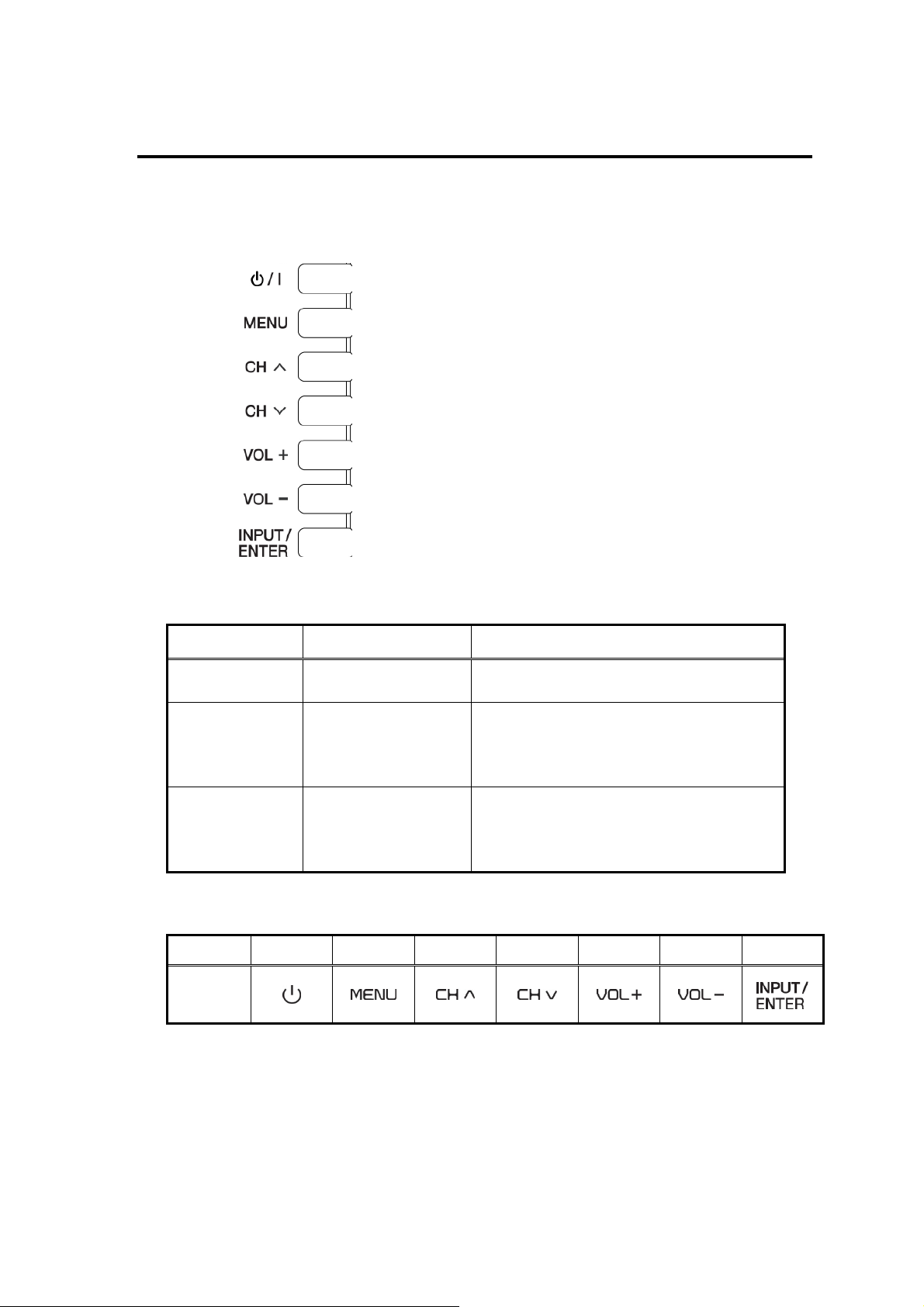
A. LED indicator display on the front
LED indicator Status Remark
Off AC power off by disconnecting the power cord
Becoming dimmer after lighting up a
Green Power on
few seconds
Becoming dimmer after lighting up a
Red Standby/Power Off
few seconds
B. Specification and explanation of user control panel on the side
Buttons 1 2 3 4 5 6 7
Name
CONFIDENTIAL – DO NOT COPY
Page 3-1
File No. SG-0361
i. Standby/power on
After AC on, by pressing button, LED indicator turns to white to indicate
power on. press 2 sec to turn off this device, press this button again.
ii. Menu operation
Press button to activate the quick menu. Press the button again to
activate function. Turn Left or Right button to select function
On Screen Display
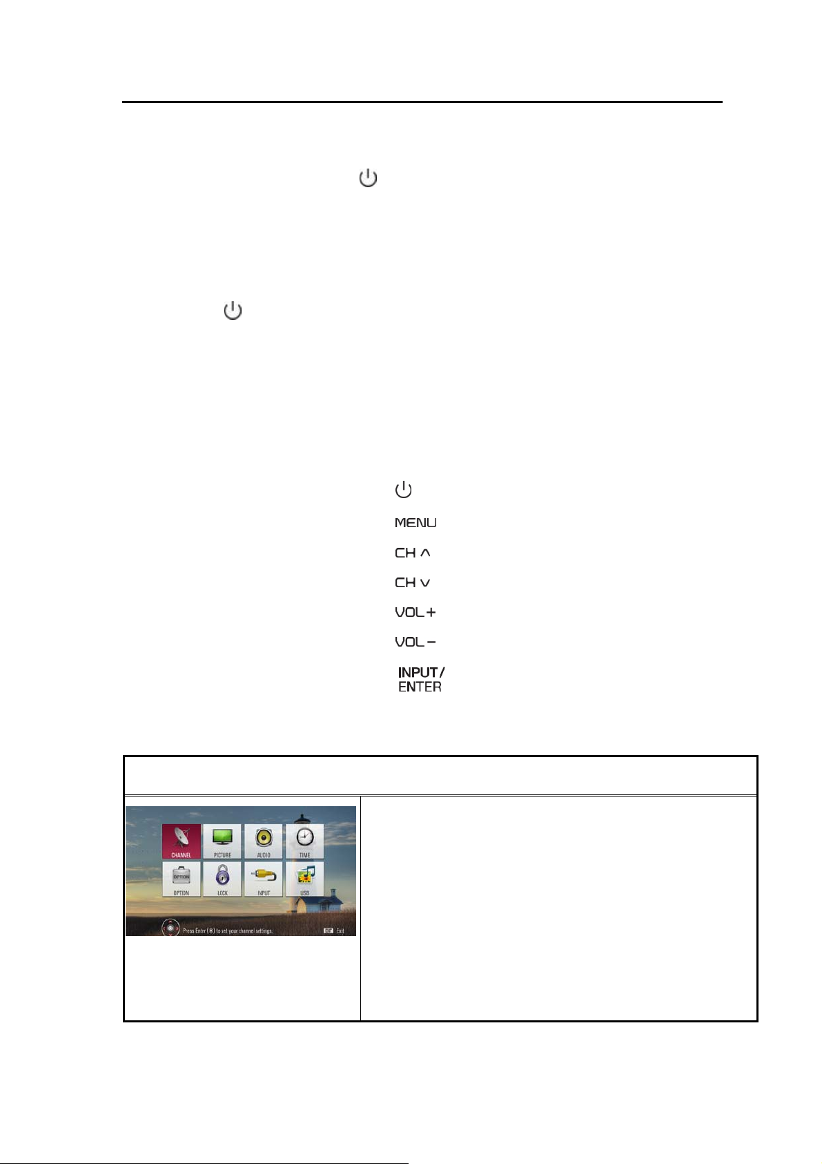
Operation:
Main unit button (1)
(2)
(3)
(4)
(5)
(6)
(7)
LGE 2008 UI Adjustment
Main Menu
Channel
Picture
Audio
CONFIDENTIAL – DO NOT COPY
Time
Option
Lock
Page 3-2
File No. SG-0361
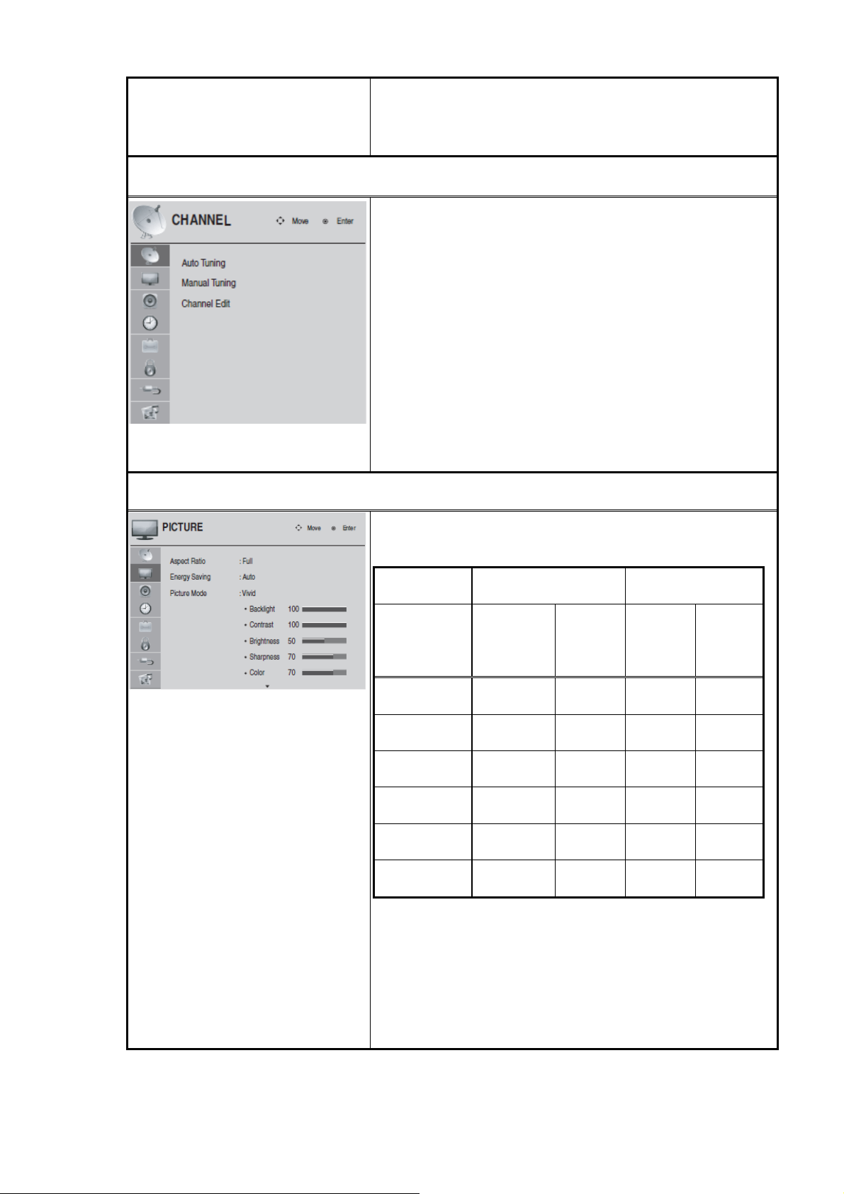
Channel
Picture
Input
My Media
A. Auto Tuning
B. Manual Tuning
a. Type: TV, CATV, DTV, CADTV
b. Channel
c. Add / Delete
d. Close
C. Channel Edit
a. Type: TV, CATV, DTV, CADTV
b. Channel Select
c. Add / Delete / Remove Favorite
A. Aspect Ratio (Set by Program, 4:3, 16:9, Zoom,
Cinema Zoom, Just Scan)
Source TV/AV/Comp/HDMI RGB
Resolution 480i/p
Set by
Program
4:3
16:9
Zoom
Cinema Zoom
Just Scan
Yes Yes N/A N/A
Yes Yes Yes Yes
Yes Yes Yes Yes
Yes Yes N/A N/A
Yes Yes N/A N/A
N/A Yes N/A N/A
720p,
480i/p
1080i/p
720p,
1080i/p
B. Energy Saving (Auto, Off, Minimum, Medium,
CONFIDENTIAL – DO NOT COPY
Maximum, Screen Off)
C. Picture Mode (Vivid, Standard, Cinema, Sport,
Game)
a. Backlight (0 ~ 100)
Page 3-3
File No. SG-0361
b. Contrast (0 ~ 100)
c. Brightness (0 ~ 100)
d. Sharpness (0 ~ 100)
e. Color (0 ~ 100)
f. Tint (R50 ~ G50)
g. Advanced Control
g-1. Color Temperature (Cool, Medium, Warm)
g-2. Fresh Contrast (Off, Low, Medium, High)
g-3. Fresh Color (Off, Low, High)
g-4. Noise Reduction (Off, Low, Medium, High)
g-5. Gamma (Low , Medium, High)
g-6. Black Level (Low, High)
g-7. Eye Care (Off, On)
g-8. Real Cinema (Off, On)
h. Reset
D. Screen (RGB-PC)
Audio
a. Resolution (1024X768, 1280X768, 1360X768)
b. Auto Config.
c. Position (H Position, V Position)
d. Size (-30 ~ 30)
e. Phase (-32 ~ 31)
f. Reset
A. Balance (L50 ~ R50)
B. Sound Mode (Standard, Music, Cinema, Sport,
Game)
a. Treble (0 ~ 100)
b. Bass (0 ~ 100)
c. Reset
C. TV Speaker (On, Off)
D. Digital Audio Out (Off, Dolby Digital, PCM)
CONFIDENTIAL – DO NOT COPY
E. Analog Audio Out (Fixed, Variable)
Page 3-4
File No. SG-0361
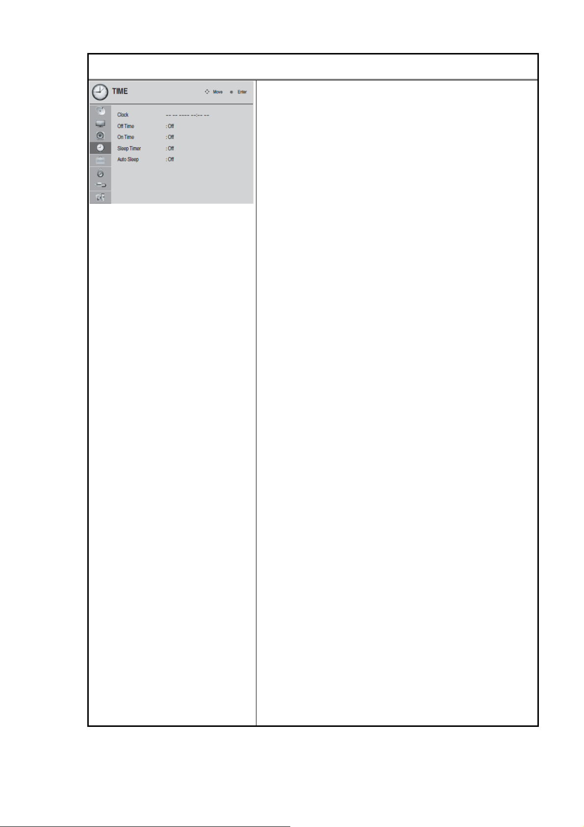
Time
A. Clock (Auto, Manual)
a. Year (2000 ~ 2035)
b. Month (1 ~ 12)
c. Date (1 ~ 31)
d. Hour (12AM ~ 11PM)
e. Minute (0 ~ 59)
f. Time Zone (Eastern, Central, Mountain, Pacific,
Alaska, Hawaii)
g. Daylight Saving (Auto, On, Off)
B. Off Time
a. Repeat (Off, Once, Everyday, Mon~Fri,
Mon~Sat, Weekend, Sunday, )
b. Hour (12AM ~ 11PM)
c. Minute (0 ~ 59)
C. On Time
a. Repeat (Off, Once, Everyday, Mon~Fri,
Mon~Sat, Weekend, Sunday)
b. Hour (12AM ~ 11PM)
c. Minute (0 ~ 59)
d. Input (TV, AV, Component, RGB-PC, HDMI1,
HDMI2, HDMI3 (42LD500 only))
e. Channel
f. Volume (0 ~ 100)
D. Sleep Timer (Off, 10 min, 20 min, 30 min, 60 min,
90 min, 120 min, 180 min, 240 min)
E. Auto Sleep (Off, On)
CONFIDENTIAL – DO NOT COPY
Page 3-5
File No. SG-0361
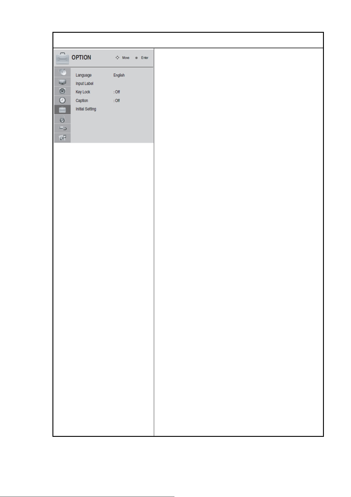
Option
A. Language
a. Menu (English, Spanish, French)
b. Audio (English, Spanish, French)
B. Input Label
a. AV (VCR, DVD, Set Top Box, Satellite, Cable
Box, Game, PC, HD-DVD, Blu-Ray)
b. Component (VCR, DVD, Set Top Box, Satellite,
Cable Box, Game, PC, HD-DVD, Blu-Ray)
c. RGB-PC (VCR, DVD, Set Top Box, Satellite,
Cable Box, Game, PC, HD-DVD, Blu-Ray)
d. HDMI1 (VCR, DVD, Set Top Box, Satellite,
Cable Box, Game, PC, HD-DVD, Blu-Ray)
e. HDMI2 (VCR, DVD, Set Top Box, Satellite,
Cable Box, Game, PC, HD-DVD, Blu-Ray)
f. HDMI3 (VCR, DVD, Set Top Box, Satellite,
Cable Box, Game, PC, HD-DVD, Blu-Ray)
(47LD500 only)
C. Key Lock (Off, On)
D. Caption (Off, On)
a. Mode (CC1 ~ Text4, Service1 ~ Service6)
b. Digital Option (Set by Program, Custom)
b-1. Size (Small, Standard, Large)
b-2. Font (Font1 ~ Font8)
b-3. Text Color (White, Black, Red, Green, Blue,
Yellow, Magenta, Cyan)
b-4. Text Opacity (Solid, Flash, Translucent,
Transparent)
b-5. Bg Color (White, Black, Red, Green, Blue,
Yellow, Magenta, Cyan)
b-6. Bg Opacity (Solid, Flash, Translucent,
CONFIDENTIAL – DO NOT COPY
Transparent)
b-7. Edge Type (None, Uniform, Raised,
Depressed, Left Shadow, Right Shadow)
b-8. Edge Color (White, Black, Red, Green,
Page 3-6
File No. SG-0361
Lock
Blue, Yellow, Magenta, Cyan)
E. Initial Setting (In Store, Home)
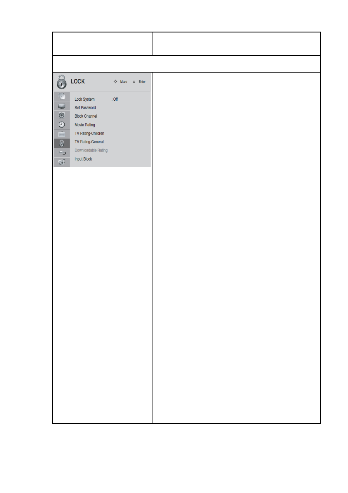
A. Lock System (Off, On) (default password: 0000)
B. Set Password
a. New
b. Confirm
C. Block Channel
a. Type: TV, CATV, DTV, CADTV
b. Channel Select
c. Block, Un-block
D. Movie Rating (Off, X, NC-17, R, PG-13, PG, G)
E. TV Rating-Children
a. Age (Off, TV-Y7, TV-Y)
b. Fantasy Violence (Off, TV-Y7)
F. TV Rating-General
a. Age (Off, TV-MA, TV-14, TV -PG, TV -G)
b. Dialogue (Off, TV-Y7)
c. Language (Off, TV -MA , TV-14, TV-PG)
d. Sex (Off, TV-MA, TV-14, TV -PG)
e. Violence (Off, TV-MA, TV-14, TV-PG)
G. Downloadable Rating
H. Input Block
a. AV (Off, On)
b. Component (Off, On)
c. RGB-PC (Off, On)
d. HDMI1 (Off, On)
e. HDMI2 (Off, On)
f. HDMI3 (Off, On) (47LD500 only)
CONFIDENTIAL – DO NOT COPY
Page 3-7
File No. SG-0361
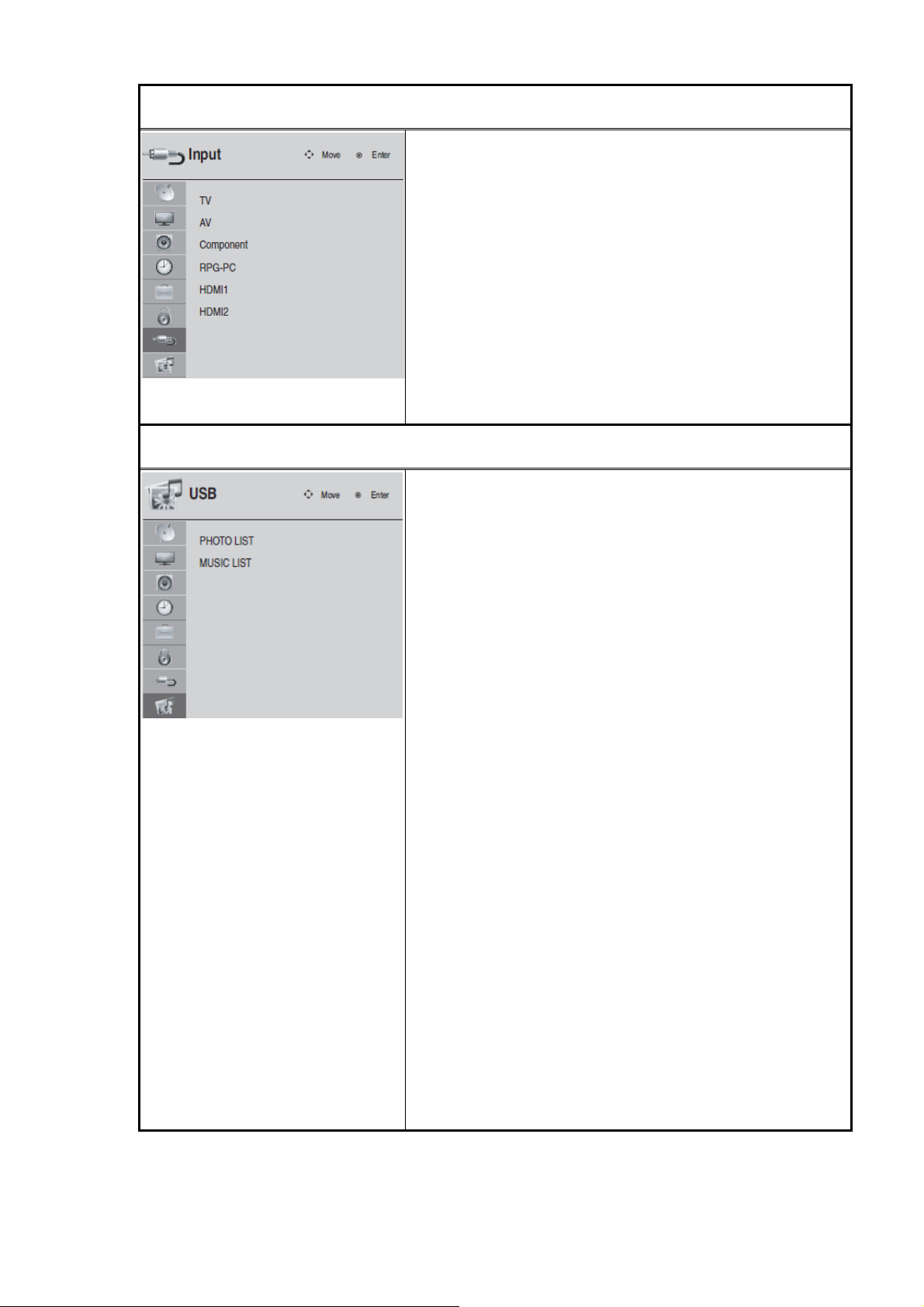
Input
TV
AV
Component
RGB-PC
HDMI-1
HDMI-2
My Media
HDMI-3 (47LD500 only)
A. Photo List
a. Slideshow Mode (Single, Sequence, Shuffle)
b. Repeat (Off, On)
c. Sort By (Photo Date, File Date, File A-Z)
d. Duration (5 ~ 32)
e. Slideshow Effect (Random, Dissolve, Wipe
Right, Wipe Left, Wipe Up, Wipe Down, Box In,
Box Out)
f. Thumbnail Size (Small, Medium, Large)
B. Music List (47LD500 only)
a. Sort By (Title/File, Genre, Artist, Album)
b. Play Mode (Single, Sequence, Shuffle)
c. Repeat (Off, On)
CONFIDENTIAL – DO NOT COPY
d. Information (Off, On)
Page 3-8
File No. SG-0361
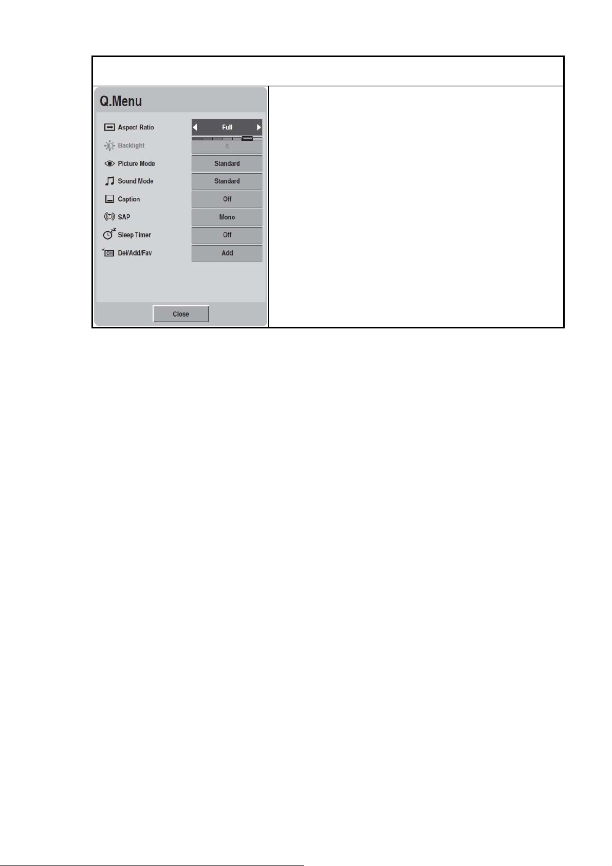
QMenu
A. Aspect Ratio (Set By Program, 4:3, 16:9, Zoom,
Cinema Zoom, Just Scan)
B. Backlight (0 ~ 6)
C. Picture Mode (Vivid, Standard, Cinema, Sport,
Game)
D. Sound Mode (Standard, Music, Cinema, Sport,
Game)
E. Caption (Off, On)
F. Multi Audio (Mono, Stereo, SAP)
G. Sleep Timer (Off, 10 min, 20 min, 30 min, 60 min,
90 min, 120 min, 180 min, 240 min)
H. Del/Add/Fav (Add, Favorite, Delete)
CONFIDENTIAL – DO NOT COPY
Page 3-9
File No. SG-0361
Chapter 4 Factory preset timings
This timing chart is already preset for the TFT LCD analog & digital display monitors.
RGB For VESA Standard:
Mode
Resolution
No.
1 640 x 480 60 31.469 59.941 N N 25.175 Windows
2 640 x 480 75 37.500 75.000 N N 31.500 Windows
3 800 x 600 60 37.879 60.317 P P 40.000 Windows
4 800 x 600 72 48.077 72.188 P P 50.000 Windows
5 800 x 600 75 46.875 75.000 P P 49.500 Windows
6 1024 x 768 60 48.363 60.004 N N 65.000 Windows
7 1024 x 768 70 56.476 70.069 N N 75.000 Windows
8 1024 x 768 75 60.023 75.029 P P 78.750 Windows
9 720 x 400 70 31.469 70.087 N P 28.322 DOS
*10 @1920 x 1080 60 66.587 59.934 P N 138.500 VESA
Remark: P: positive, N: negative 1920x1080 @60 Hz: Primary
*Note: VESA Reduced Blanking Timing mode, see Table below.
Refresh
Rate
(Hz)
Horizontal
Frequency
(KHz)
Vertical
Frequency
(Hz)
Horizontal
Sync
Polarity
(TTL)
Vertical
Sync
Polarity
(TTL)
Pixel
Rate
(MHz)
Remark
Resolution (1920x1080) through RGB (15-Pin D connector)
Parameters Horizontal Values (Pixels) Vertical Values (Lines)
Address 1920 1080
Front Porch 48 2
Sync Width 32 5
Back Porch 80 24
Total 2080 1111
Frequency 66.587 KHz 59.93 Hz
Sync Polarity P N
Pixel Rate (MHz) 138.5
Refresh Rate (Hz) 60
CONFIDENTIAL – DO NOT COPY
File No. SG-0361
Page 4-1
FHD video digital preset modes at HDMI
Mode No. Resolution
1 480i
2 480p
3 720p
4 1080i
5 1080p
Video input
Mode No. Resolution
1 480i
2 480p
3 720p
4 1080i
5 1080p
CONFIDENTIAL – DO NOT COPY
Page 4-2
File No. SG-0361
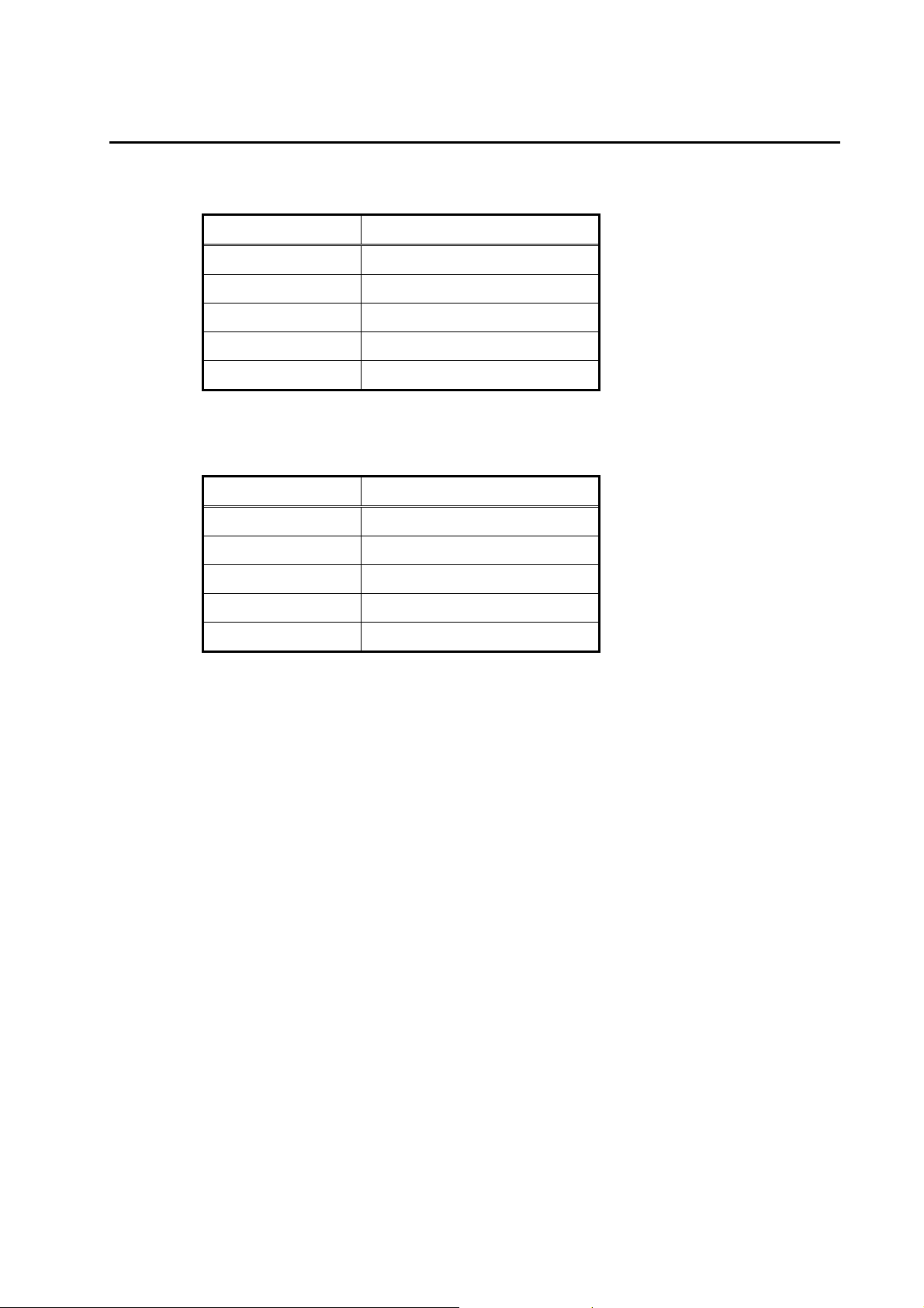
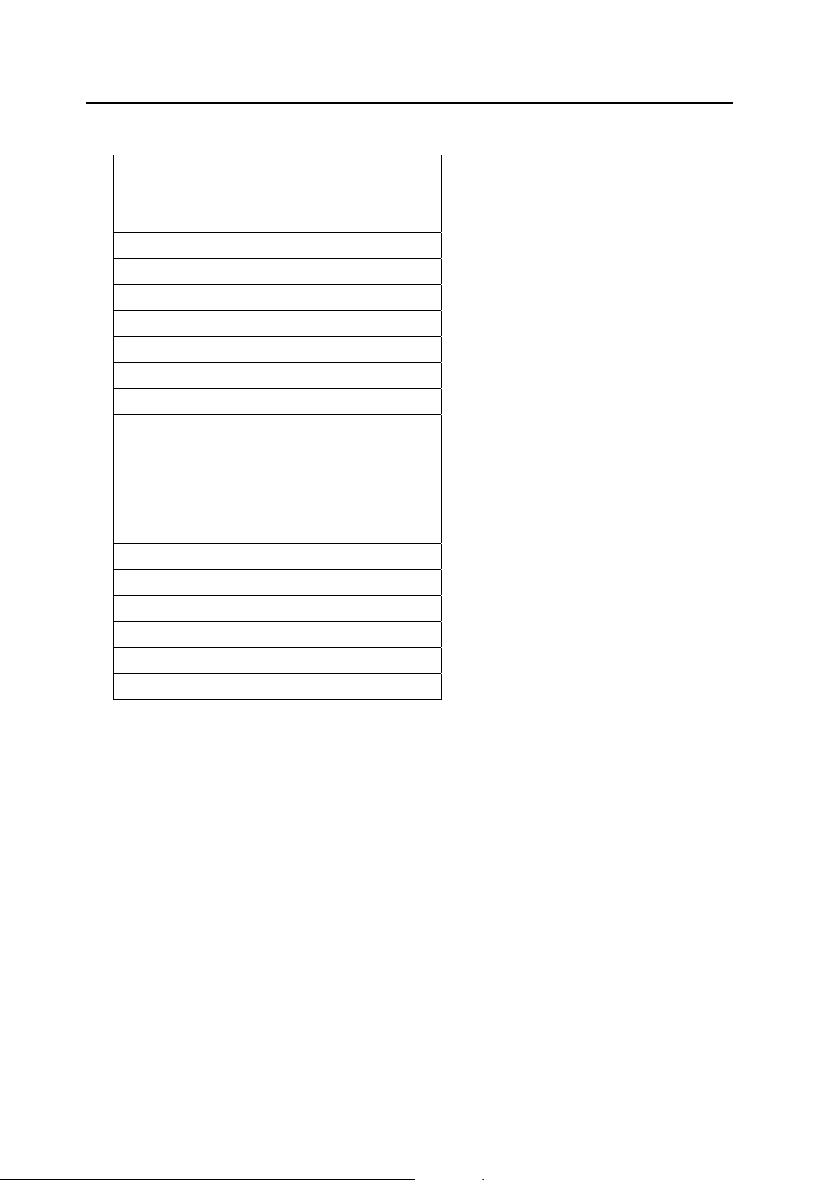
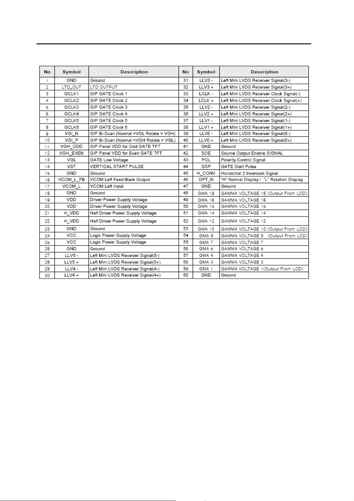
Chapter 5 Pin Assignment
The TFT LCD monitors use a 15 Pin Mini D-Sub connector as video input source.
Pin Pin Assignment Pin Pin Assignment
1 Red video input 9 +5V
2 Green video input 10 Ground
3 Blue video input 11 No connection
4 Ground 12 (SDA)
5 Ground 13
6 Red video ground 14 Vertical sync
7 Green video ground 15 (SCL)
8 Blue video ground
Horizontal sync
(Composite sync)
RGB Signal:
1
11
5
106
15
a. Sync Type TTL (Separate / Composite) or Sync. On Green
b. Sync polarity Positive or Negative
c. Video Amplitude RGB: 0.7Vp-p
d. Frequency H: support to 30K~70KHz
V: support to 60~85Hz
e. Pixel Clock: support to 138.5 MHz
f. Connector type: 15-pin D-Sub, female
g. Impedance: 75
CONFIDENTIAL – DO NOT COPY
Page 5-1
File No. SG-0361
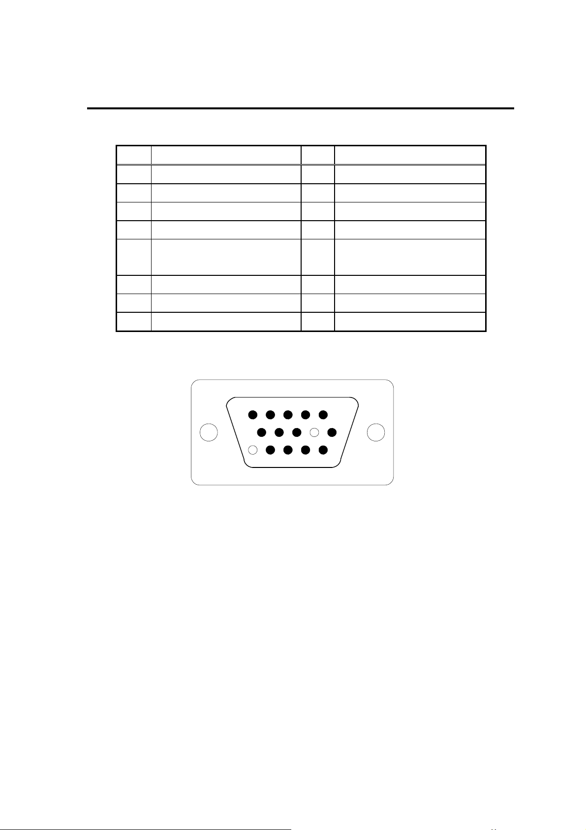
HDMI CONNECT PIN ASSIGNMENT:
Pin Signal Assig nment Pin Signal Assignment
1 TMDS Data2+ 2 TMDS Data2 Shield
3 TMDS Data2- 4 TMDS Data1+
5 TMDS Data1 Shield 6 TMDS Data1-
7 TMDS Data0+ 8 TMDS Data0 Shield
9 TMDS Data0- 10 TMDS Clock+
11 TMDS Clock Shield 12 TMDS Clock-
13 CEC 14 Reserved (N.C. on device)
15 SCL 16 SDA
17 DDC/CEC Ground 18 +5V Power
19 Hot Plug Detect
HDMI Signal (HDMI):
a. Pin Assignment Refer to HDMI Pin Assignment
b. Type A
c. Polarity Positive or Negative
d. Frequency
H: 15.734KHz V: 60Hz (NTSC-480i)
H: 31KHz V: 60Hz (NTSC-480p)
H: 45KHz V: 60Hz (NTSC-720p)
H: 33KHz V: 60Hz (NTSC-1080i)
H: 67.5KHz V: 60Hz (NTSC-1080P)
CONFIDENTIAL – DO NOT COPY
Page 5-2
File No. SG-0361

F-Type TV RF connector
NTSC system
Signal level: Analog 1Vp-p Typical
Frequency: 55.25~855.25 MHz
ATSC system
IF-output level: 1Vp-p minimum
Frequency: 57.00~861.00 MHz
QAM system (supporting clear QAM)
IF-output level: 1Vp-p minimum
Frequency: 57.00~861.00 MHz
AV/Composite Video (CVBS) Connector
a. Frequency: H: 15.734KHz V: 60Hz (NTSC)
b. Signal level: Video ( Y + C ):1Vp-p
Sync (H+V):0.3V below Video (Y+C)
c. Impedance: 75
d. Connector type: RCA Jack
Component video Connector
a. Frequency: H: 15.734KHz V: 60Hz (NTSC-480i)
H: 31KHz V: 60Hz (NTSC-480p)
H: 45KHz V: 60Hz (NTSC-720p)
H: 33KHz V: 60Hz (NTSC-1080i)
H: 67.5KHz V: 60Hz (NTSC-1080P)
b. Signal level: Y: 1Vp-p Pb: ±0.350Vp-p Pr: ±0.350Vp-p
c. Impedance: 75
d. Connector type: RCA Jack
PC audio in
a. Signal level: 0.7Vrms
b. Impedance: 47K
c. Frequency: 20Hz-20KHz
d. Connector type: 3.5 mini jack
CONFIDENTIAL – DO NOT COPY
Page 5-3
File No. SG-0361

Video audio in
a. Signal level: 0.7Vrms
b. Impedance: 47K
c. Frequency Response: 20Hz-20KHz
d. Connector type: RCA L/R
Digital Audio Out (Optical)
a. Peak emission wave length: 630 – 690 nm
b. Transmission Speed: 16M bps (Max)
c. Connector type: Optical fiber transmitter
Analog Audio out
a. Signal level: 2 Vrms (Max)
b. Impedance: 600
c. Frequency Response: 20Hz-20KHz
d. Connector type: RCA L/R
CONFIDENTIAL – DO NOT COPY
Page 5-4
File No. SG-0361
Chapter 6 Main Board I/O Connections
J4 CONNECTION [Main BD to Power BD]
Pin Description
1 +5VSB
2 +5VSB
3 +5VSB
4 GND
5 GND
6 GND
7 GND
8 +12V
9 +12V
10 +12V
11 POWER SW ON OFF
12 BL ON OFF
13 Lamp Status
14 PWM DIM
J7 CONNECTION [MAIN BD TO LED LOGO]
Pin Description
1 5VSB
2 WHITE
3 AMBER
JD1CONNECTION [MAIN BD TO IR LIGHT SENSOR BD]
Pin Description
1 OIRI_in
2 5VSB
3 GND
4 LS_SCL
5 LS_SDA
6 reserve
CONFIDENTIAL – DO NOT COPY
Page 6-1
File No. SG-0361
J2 CONNECTION [JTAG INTERFACE]
Pin Description
1 AV33
2 TVTREF#1
3 GND
4 JTRST#
5 GND
6 JTDI
7 GND
8 JTMS
9 GND
10 JTCK
11 GND
12 Pull High AV33
13 GND
14 JTDO
15 GND
16 N.C.
17 GND
18 JTAG DBGRQ
19 GND
20 JTAG DBGACK
CONFIDENTIAL – DO NOT COPY
Page 6-2
File No. SG-0361
TCN1 CONNECTION
CONFIDENTIAL – DO NOT COPY
Page 6-3
File No. SG-0361
TCN2 CONNECTION
J5 CONNECTION [Main BD to SPEAKER]
Pin Description
1 R+
2 R-
3 L+
4 L-
CONFIDENTIAL – DO NOT COPY
Page 6-4
File No. SG-0361

Chapter 7 Theory of Circuit Operation
The route of D-SUB 15pin input
An RGB (analog) signal is inputted the D-SUB 15pin to the MT5387 which transfers it to a digital
signal by the A/D converter. Then MT5387
display device. The Extended Display Identification (EDID) code is recorded in EEPROM.
generates a Low Voltage Differential Signal (LVDS) for
The route of HDMI CON input
A HDMI (Digital) signal is inputted the HDMI 1&2 CON to the PI3HDMI301 switch. The passing
signal is processed with the MT5387
. Then MT5387 generates a LVDS for display device.
The route of HDTV & Component input
HDTV & Component signal is inputted to the MT5387.After processing, MT5387 generates a LVDS
for display device. The audio signal is inputted MT5387
signal to audio output. an audio amplifier and line out.
. After processing, MT5387 transmits the
The route of CVBS input
The CVBS signal is inputted to the MT5387.After processing, MT5387 generates a LVDS for display
device. The audio signal is also inputted MT5387
audio amplifier. Then, the amplified signal is the output audio signal.
. After processing, MT5387 transmits the signal to
The route of TV input
TV signal is demodulated by the tuner then the demodulating signal is divided into two parts, video
and audio signal. The video signal is processed by MT5387
display device. The audio signal is transmitted in the route named SIF. The SIF signal is
demodulated and decoded by MT5387
signal to audio amplifier. Then, the amplified signal is the output audio signal.
. The audio signal is inputted MT5387. MT5387 transmits the
then MT5387 generates a LVDS for
The route of DTV input
DTV signal demodulated by the tuner then the demodulating signal is divided into two parts, video
and audio signal. The video signal is demodulated by MT5387
transmitted to and processed by MT5387
The audio signal is transmitted in the route named FAT-IN. The FAT-IN signal is demodulated and
decoded by MT5387
amplified signal is the output audio signal.
CONFIDENTIAL – DO NOT COPY
. After processing, MT5387 transmits the signal to audio amplifier. Then, the
. Also, MT5387 generates a LVDS for display device.
. The demodulated signal is
Page 7-1
File No. SG-0361

The operation of keypad
There are Jag Wheel/Button to control and to select the function of 32LD400/ 42LD400. Also, there
is a LED back light to indicate the status of operation (Red → STANDBY, Green → ON).
MT5387
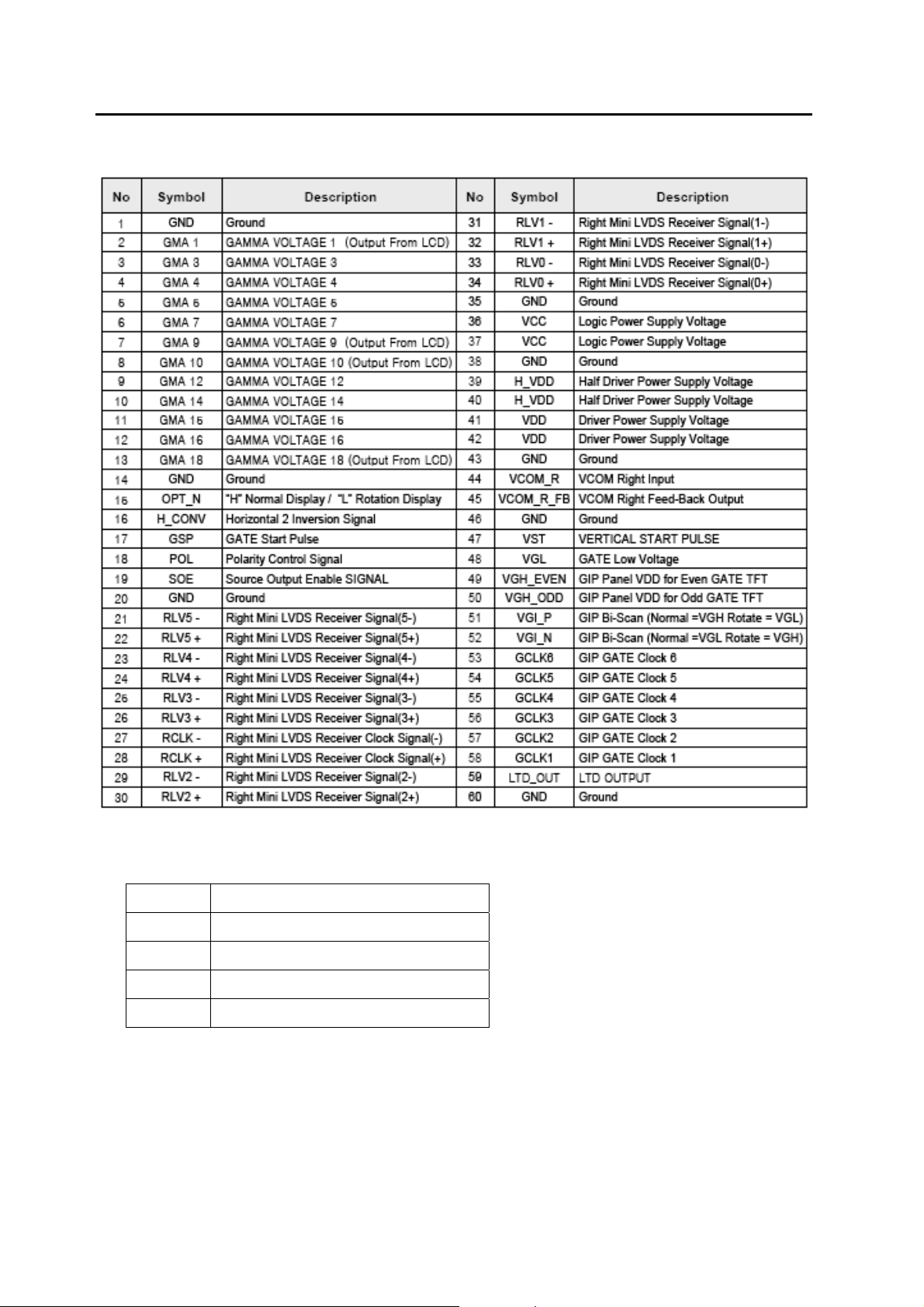
Ⅰ. GENERAL DESCRIPTION
The MediaTek MT5387 family is a backend decoder and a TV controller and offers high integration
for advanced applications. It combines a transport de-multiplexer, a high definition video decoder, an
AC3 audio decoder, a dual-link LVDS transmitter, and an NTSC/PAL/SECAM TV decoder with a 3D
comb filter (NTSC/PAL). The MT5387 enables consumer electronics manufactures to build high
quality, low cost and feature-rich DTV.
World-Leading Audio/Video T echnology: The MT5387 supports MPEG2 Full-HD video decoder
standards, and JPEG. The MT5387 also supports MediaTek MDDiTM de-interlace solution can reach
very smooth picture quality for motions. A 3D comb filter added to the TV decoder recovers great
details for still pictures. The special color processing technology provides natural, deep colors and
true studio quality video. Also, the MT5387 family has built-in high resolution and high-quality audio
codec.
Rich Features for High Value Products: The MT5387 family enables true single-chip experience.
It integrates high-quality HDMI1.3, high speed VGA ADC, dual-channel LVDS, USB2.0 receiver and
multi-media decoder.
Key Features:
1. ATSC demodulator
2. Worldwide multi-standard analog TV demodulator
3. A transport demultiplexer
4. A MPEG2 video decoder
5. An AC3/MPEG2 audio decoder
6. HDMI1.3 receiver
7. Audio codec
CONFIDENTIAL – DO NOT COPY
Page 7-2
File No. SG-0361
Functional Block Diagram
GENERAL FEATURE LIST
Host CPU
1. ARM926EJS
2. 16K I-Cache and 16K D-Cache
3. 16K Boot ROM
4. 8KB Instruction TCM
5. JTAG ICE interface
6. Watch Dog timers
7. Build-in CPI analyzer and Cache Hit Rate Meter
CONFIDENTIAL – DO NOT COPY
Page 7-3
File No. SG-0361
 Loading...