How it Works
Log In / Sign Up
Buy Points
How it Works
FAQ
Contact Us
Questions and Suggestions
Users
LG
Loading...
#
32LD320N
6
32LD320N-ZA
3
32LD321
4
32LD321N-ZB
32LD321-ZB
32LD322H
5
32LD325
5
32LD325C
2
32LD325H
7
32LD325N-ZA
32LD325-ZA
32LD328-ZA
32LD33
32LD330
13
32LD330H
7
32LD330H-UA
2
32LD330-MA
32LD330-TA
2
32LD331C
32LD331C-TA
32LD333H
32LD333HUA
32LD335
32LD335-ZA
32LD336-ZB
32LD34
32LD340
12
32LD340H
7
32LD340HUA
3
32LD340-MB
2
32LD341
3
32LD343H
32LD345
4
32LD345H
5
32LD346
2
32LD34 Series
2
32LD35
32LD350
35
32LD350C
11
32LD350-DB
32LD350N
5
32LD350N-ZA
32LD350UA
3
32LD350-UB
32LD350-ZA
32LD351
6
32LD355
32LD358
3
32LD358-ZA
32LD35 Series
2
32LD360L
32LD360LUA
32LD4
3
32LD400
7
32LD4000
32LD400_LC320WUG-SCR7
32LD420
34
32LD420C
13
32LD420N
4
32LD420-UA
2
32LD425
32LD428
32LD450
31
32LD450C
2
32LD450N
2
32LD450UA
32LD452B
4
32LD452C
4
32LD452CUA
32LD455
32LD455B
32LD455H
32LD458
32LD460
15
32LD460B
32LD461C
3
32LD462B
2
32LD462C
3
32LD465
10
32LD465C
2
32LD465-DA
32LD480-ZB
32LD490
2
32LD490-ZB
32LD4 Series
3
32LD5
32LD5000
32LD520
9
32LD520UA
32LD540
3
32LD550
30
32LD550N
4
32LD550N-ZC
32LD550UB
32LD550-ZC
32LD551
3
32LD551N-ZA
32LD551-ZA
32LD555
4
32LD5 Series
3
Loading...
Loading...
Nothing found
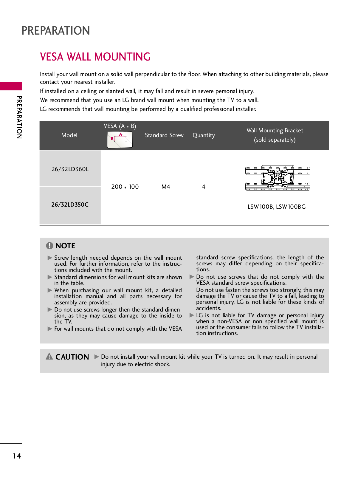
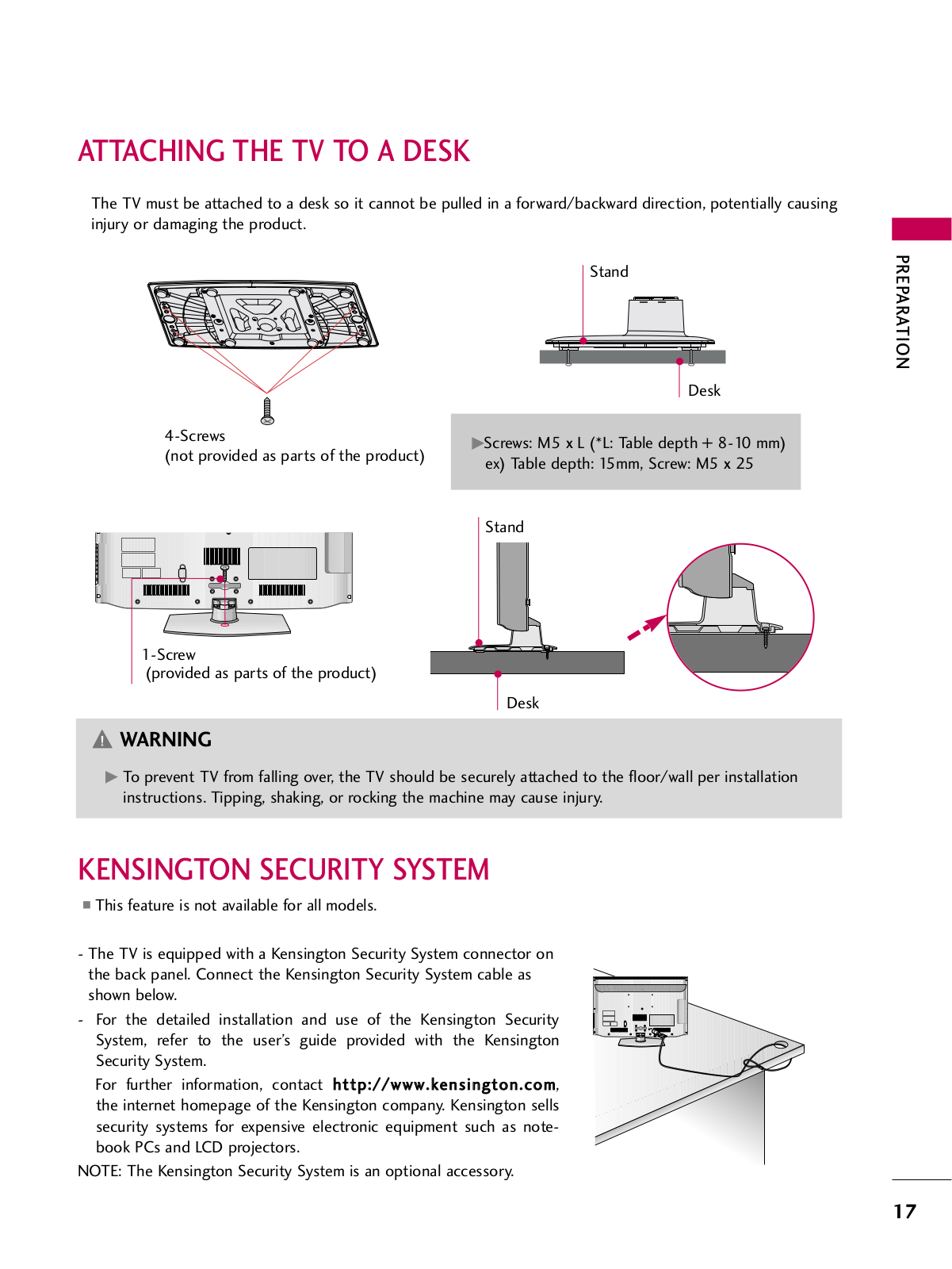
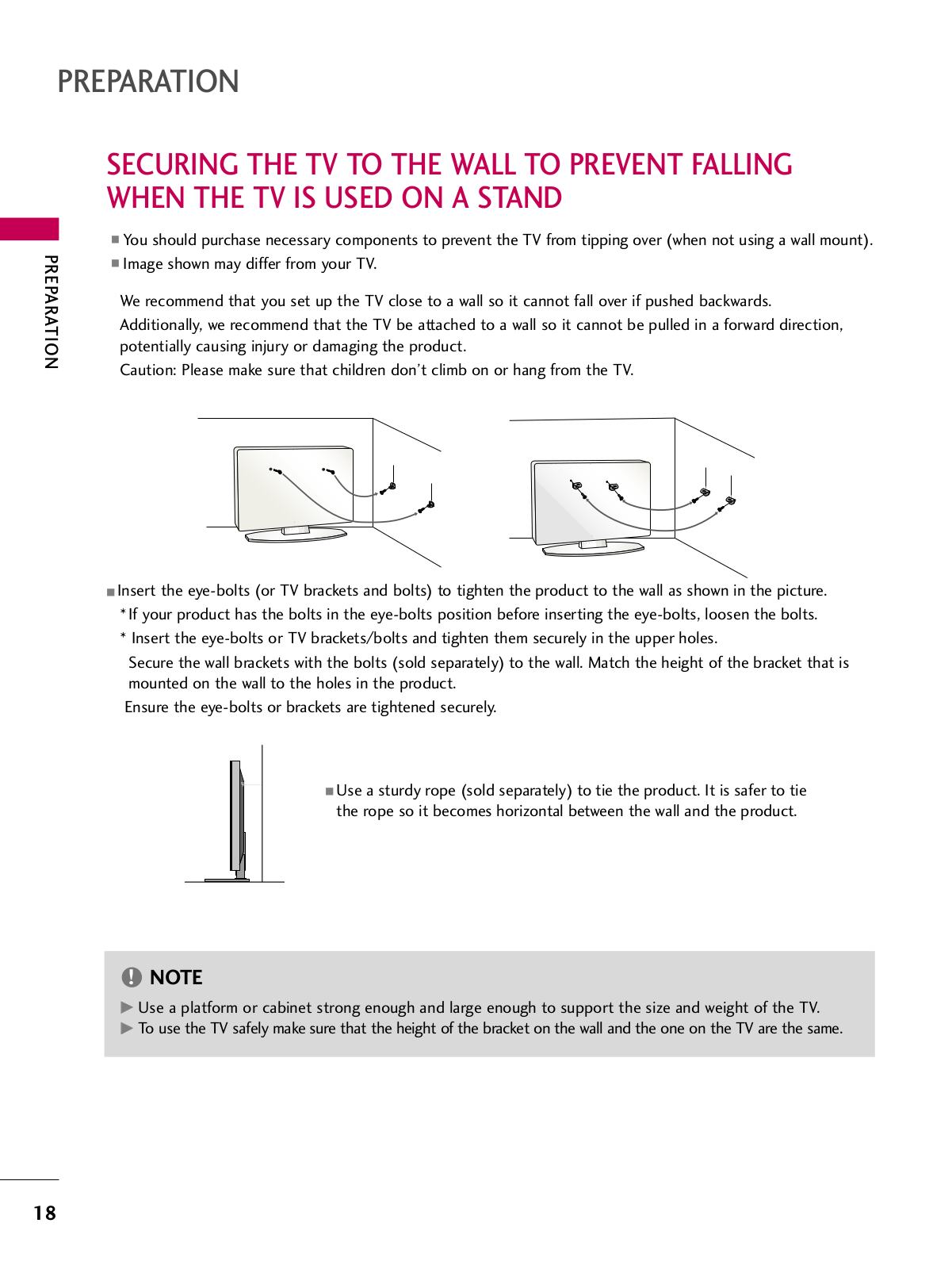
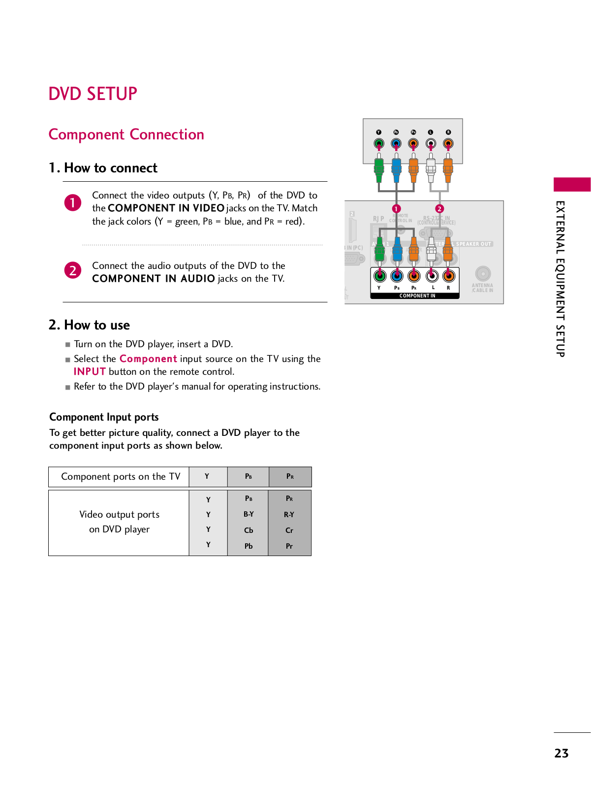
32LD360L
Owner's Manual
126 pgs
3.86 Mb
0
Table of contents
Loading...
LG 32LD360L, 26LD350C Owner's Manual
...
LG Owner's Manual
Download
Specifications and Main Features
Frequently Asked Questions
User Manual
Download
Loading...
+
96
hidden pages
Unhide
You need points to download manuals.
1 point = 1 manual.
You can buy points or you can get point for every manual you upload.
Buy points
Upload your manuals
 Loading...