

LG 32LD345 Owner’s Manual

OWNER’S MANUAL
LCD TV
Please read this manual carefully before operating
your set and retain it for future reference.
www.lg.com

HDMI, the HDMI logo and High-Definition
Multimedia Interface are trademarks or registered
trademarks of HDMI Licensing LLC.
1
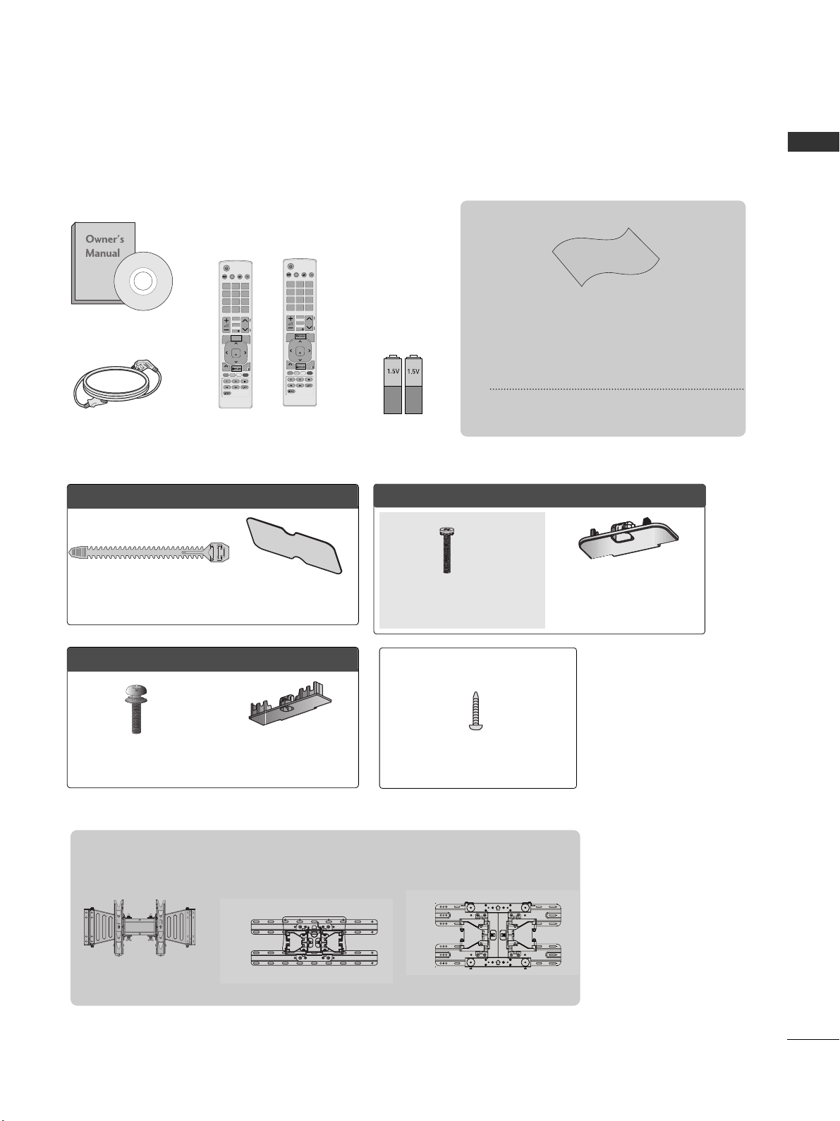
ACCESSORIES
ACCESSORIES
Bolts for stand assembly
(Refer to p. 10)
x 4
Protection cover
(Refer to p. 11)
Ensure that the following accessories are included with your TV.
If an accessory is missing, please contact the dealer where you purchased the TV.
■
Image shown may be somewhat different from your TV.
Owner’s Manual
Batteries (AAA)
Power Cord
Polishing Cloth
Polishing cloth for use on the screen.
This item is not included for all models.
* Lightly wipe any stains or fingerprints on
the surface of the TV with the polishing
cloth.
Do not use excessive force. This may cause
scratching or discolouration.
Remote Control
P
A
G
E
P
123
4506
789
LIST
Q.VIEW
AV MODE INPUTENERGY
SAVING
MARK
FAV
RATIO
MUTE
OK
MENU
Q.MENU
BACK
EXIT
CLEAR
VOICE II
OOnnllyy 1199//2222LLDD33****
Protection cover
(Refer to p. 11)
Cable Holder
(Refer to p. 12)
Bolts for stand assembly
(Refer to p. 9)
OOnnllyy 2266//3322LLDD33****
Protection cover
(Refer to p. 11)
x 8
M4 x 20
1-screw for stand fixing
(Refer to p. 10)
Wall Mounting Bracket(Separate purchase)
AW-47LG30M
(32LD4**)
OOnnllyy 3322//4422LLDD44****
Only 26/32LD3**,
32/42LD4**
P
A
G
E
P
123
4506
789
LIST
Q.VIEW
AV MODE INPUTENERGY
SAVING
MARK
FAV
RATIO
MUTE
OK
MENU
Q.MENU
BACK
EXIT
or
LSW100B or
LSW100BG
(19/22/26/32LD3**)
LSW200B or
LSW200BG
(42LD4**)

CONTENTS
2
CONTENTS
ACCESSORIES
. . . . . . . . . . . . . . . . . . . . . . . . . . . . . . . . . . . . . . . . . . . .
1
PREPARATION
Front Panel Controls..................................................... 4
Back Panel Information ................................................ 6
Stand Installation......................................................... 10
Swivel Stand ................................................................. 11
Attaching the TV to a desk .........................................11
Positioning your Display ........................................... 11
Not Using the desk-type stand.................................12
Back Cover for Wire Arrangement........................... 13
Careful Installation Advice......................................... 14
Desktop Pedestal Installation................................... 14
Wall Mount: Horizontal Installation........................ 15
Kensington Security System .................................... 15
Antenna Connection................................................... 16
EXTERNAL EQUIPMENT SETUP
HD Receiver Setup...................................................... 17
DVD Setup .....................................................................20
VCR Setup......................................................................22
USB in Setup ............................................................... 23
Other A/V Source Setup........................................... 24
External Stereo Setup ................................................ 25
AV Output Setup ........................................................ 26
PC Setup........................................................................ 26
- Screen Setup for PC Mode .............................. 28
WATCHING TV / PROGRAMME CONTROL
Remote Control Key Functions................................ 32
Turning on the TV....................................................... 36
Programme Selection ................................................ 36
Volume Adjustment .....................................................36
Quick Menu ................................................................. 37
On-Screen Menus Selection and Adjustment..... 38
Auto Programme Tuning............................................ 39
Manual Programme Tuning ....................................... 40
Programme Edit............................................................ 42
Selecting the Programme List ...................................44
Favourite Programme Setup...................................... 45
Input List........................................................................ 46
Input Label .................................................................... 47
..................................................................48
Key Lock......................................................................... 50
Initializing(Reset to original factory settings)...... 51
AV Mode........................................................................ 52
TO USE A USB DEVICE
When connecting the USB device.......................... 53
Photo List ...................................................................... 55
Music List........................................................................59
Movie List........................................................................62
DivX Registration Code..............................................66
Deactivation...................................................................67
PICTURE CONTROL
Picture Size (Aspect Ratio) Control ...................... 68
Energy Saving............................................................... 70
Preset Picture Settings
- Picture Mode-Preset............................................ 71
Manual Picture Adjustment
- Picture Mode-User option................................. 72
Picture Improvement Technology........................... 73
Expert Picture Control ................................................74
Picture Reset................................................................. 77
Power Indicator..............................................................78
Demo Mode.................................................................. 79
Mode Setting................................................................ 80

CONTENTS
3
SOUND & LANGUAGE CONTROL
Auto Volume Leveler................................................... 81
Preset Sound Settings - Sound Mode................... 82
Sound Setting Adjustment - User Mode ...............83
Infinite Sound............................................................... 83
SRS TruSurround XT .................................................. 84
Clear Voice ll................................................................. 85
Balance........................................................................... 85
TV Speakers On/ Off Setup..................................... 86
Selecting Audio Out................................................... 87
Audio Reset....................................................................88
I/II
- Stereo/Dual Reception....................................... 89
- NICAM Reception.............................................................. 90
- Speaker Sound Output Selection.................... 90
On-Screen Menu Language Selection ......................... 91
TIME SETTING
Clock Setup .................................................................. 92
Auto On/ Off Timer Setting..................................... 93
Sleep Timer Setting .................................................... 93
TELETEXT
Switch on/off ............................................................... 94
SIMPLE Text.................................................................. 94
TOP Text........................................................................ 94
FASTEXT........................................................................ 95
Special Teletext Functions......................................... 95
APPENDIX
Troubleshooting........................................................... 96
Maintenance ................................................................ 98
Product Specifications............................................... 99
IR Codes ...................................................................... 101
External Control Device Setup...............................102
4
PREPARATION
PREPARATION
P
P
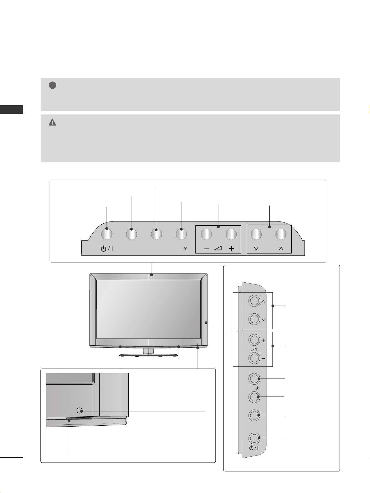
FRONT PANEL CONTROLS
■
Image shown may be somewhat different from your TV.
INPUT
MENU
OK
P
P
OK
MENU
INPUT
P
PROGRAMME
VOLUME
OK
MENU
POWER
INPUT
Only 26/32LD3**
PROGRAMME
VOLUME
OK
MENU
INPUT
POWER
Only 19/22LD3**
P
Remote Control Sensor
Power/Standby Indicator
•
Illuminates red in standby mode.
• Illuminates blue when the TV is switched on.
G
Do not step on the glass stand or subject it to any impact.
It may break, causing possible injury from fragments of glass, or the TV may fall.
G
Do not drag the TV. The floor or the product may be damaged.
CAUTION
NOTE
!
G
The energy consumed during use can be significantly reduced if the level of brightness of the picture is
reduced, and this will reduce the overall running cost.
SPEAKER

5
PREPARATION
PROGRAMME
VOLUME
OK
MENU
INPUT
POWER
Remote Control Sensor
Power/Standby Indicator
• Illuminates red in standby mode.
•
Illuminates blue when the TV is switched on.
■
Image shown may be somewhat different from your TV.
Only 32/42LD4
**
SPEAKER
P
OK
MENU
INPUT
6
PREPARATION
PREPARATION
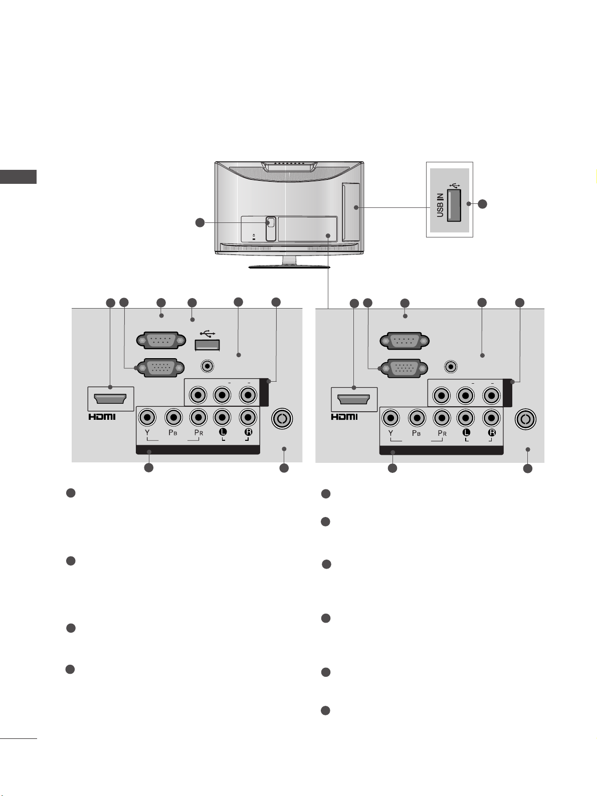
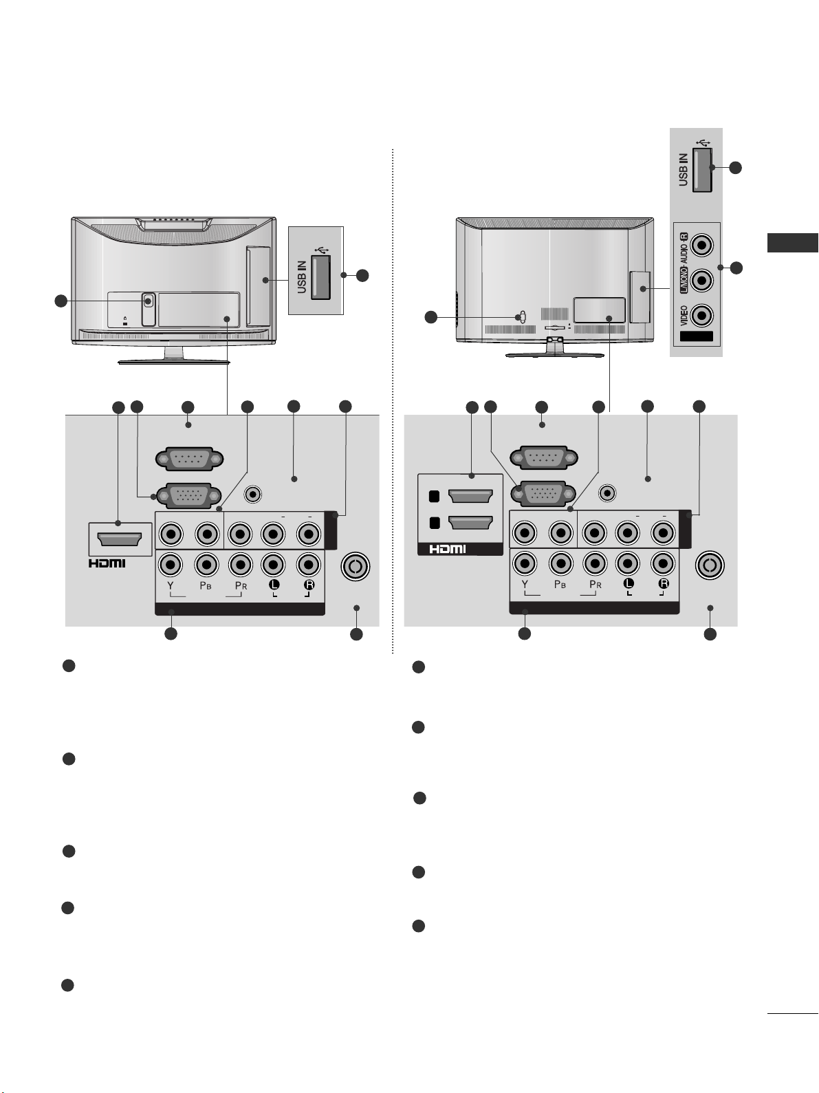
BACK PANEL INFORMATION
■
Image shown may be somewhat different from your TV.
K
AC-IN
1
Power Cord Socket
This TV operates on an AC power. The voltage is
indicated on the Specifications page. Never
attempt to operate the TV on DC power.
HDMI Input
Connect a HDMI signal to HDMI IN.
Or DVI(VIDEO)signal to HDMI/DVI port with DVI
to HDMI cable.
RGB IN Input
Connect the output from a PC.
RS-232C IN PORT
Connect to the RS-232C port on a PC.
This port is used for Service or Hotel mode.
SERVICE ONLY PORT
RGB/DVI Audio Input
Connect the audio from a PC.
Audio/Video Input
Connect audio/video output from an external
device to these jacks.
Component Input
Connect a component video/audio device to
these jacks.
Antenna Input
Connect RF antenna to this jack.
USB IN Input
Connect USB storage device to this jack.
1
2
3
4
5
7
6
8
9
COMPONENT IN
AUDIO
VIDEO
ANTENNA
IN
L(L(MONO)MONO)
R
AUDIOAUDIO
VIDEOVIDEO
AV IN
AUDIO IN
(RGB/DVI)
USB IN
SERVICE ONLY
RGB IN
(PC)
RS-232C IN
(CONTROL)
/DVI IN
2
8
9
3
6
7
Only
19/22LD33*
4 5
COMPONENT IN
AUDIO
VIDEO
ANTENNA
IN
L(L(MONO)MONO)
R
AUDIOAUDIO
VIDEOVIDEO
AV IN
AUDIO IN
(RGB/DVI)
RGB IN
(PC)
RS-232C IN
(CONTROL)
/DVI IN
2
8
9
3
6
7
4
10
Only
19/22LD34*
(Except 19/22LD345)
Only
19/22LD34*
(Except 19/22LD345)
10

7
PREPARATION
■
Image shown may be somewhat different from your TV.
AC IN
CABLE MANAGEMENT
1
Only
26/32LD33*
MONO
AUDIO
VIDEO
ANTENNA
IN
L( MONO)
R
AUDIO
VIDEO
2
8
9
3
6
7
4 5
7
COMPONENT IN
AUDIO
VIDEO
ANTENNA
IN
L/L/MONOMONO
R
AUDIOAUDIO
VIDEOVIDEO
AV IN1
1
AUDIO IN
(RGB/DVI)
RGB IN
(PC)
RS-232C IN
(CONTROL)
ANTENNA
IN
L( MONO)
R
AUDIO
VIDEO
2
/DVI IN
2
8
9
3
6
7
4
AV IN2
7
10
Only
26/32LD34*(Except 26/32LD345)
Only
26/32LD34*
(Except 26/32LD345)
Only
26/32LD33*
Power Cord Socket
This TV operates on an AC power. The voltage is
indicated on the Specifications page. Never
attempt to operate the TV on DC power.
HDMI Input
Connect a HDMI signal to HDMI IN.
Or DVI(VIDEO)signal to HDMI/DVI port with DVI
to HDMI cable.
RGB IN Input
Connect the output from a PC.
RS-232C IN PORT
Connect to the RS-232C port on a PC.
This port is used for Service or Hotel mode.
SERVICE ONLY PORT
RGB/DVI Audio Input
Connect the audio from a PC.
Audio/Video Input
Connect audio/video output from an external
device to these jacks.
Component Input
Connect a component video/audio device to
these jacks.
Antenna Input
Connect RF antenna to this jack.
USB IN Input
Connect USB storage device to this jack.
1
2
3
4
5
7
6
8
9
10
2
1
/DVI IN
RS-232C IN
(CONTROL)
RGB IN
(PC)
VIDEO
COMPONENT IN
USB IN
SERVICE ONLY
VIDEO
L/L/MONO
AUDIO IN
(RGB/DVI)
AUDIO
AUDIO
R
AV IN1
ANTENNA
IN
AV IN2
ANTENNA
IN
L/MONO
R
AUDIO
VIDEO
ANTENNA
IN
L(MONO)
R
AUDIO
VIDEO
8
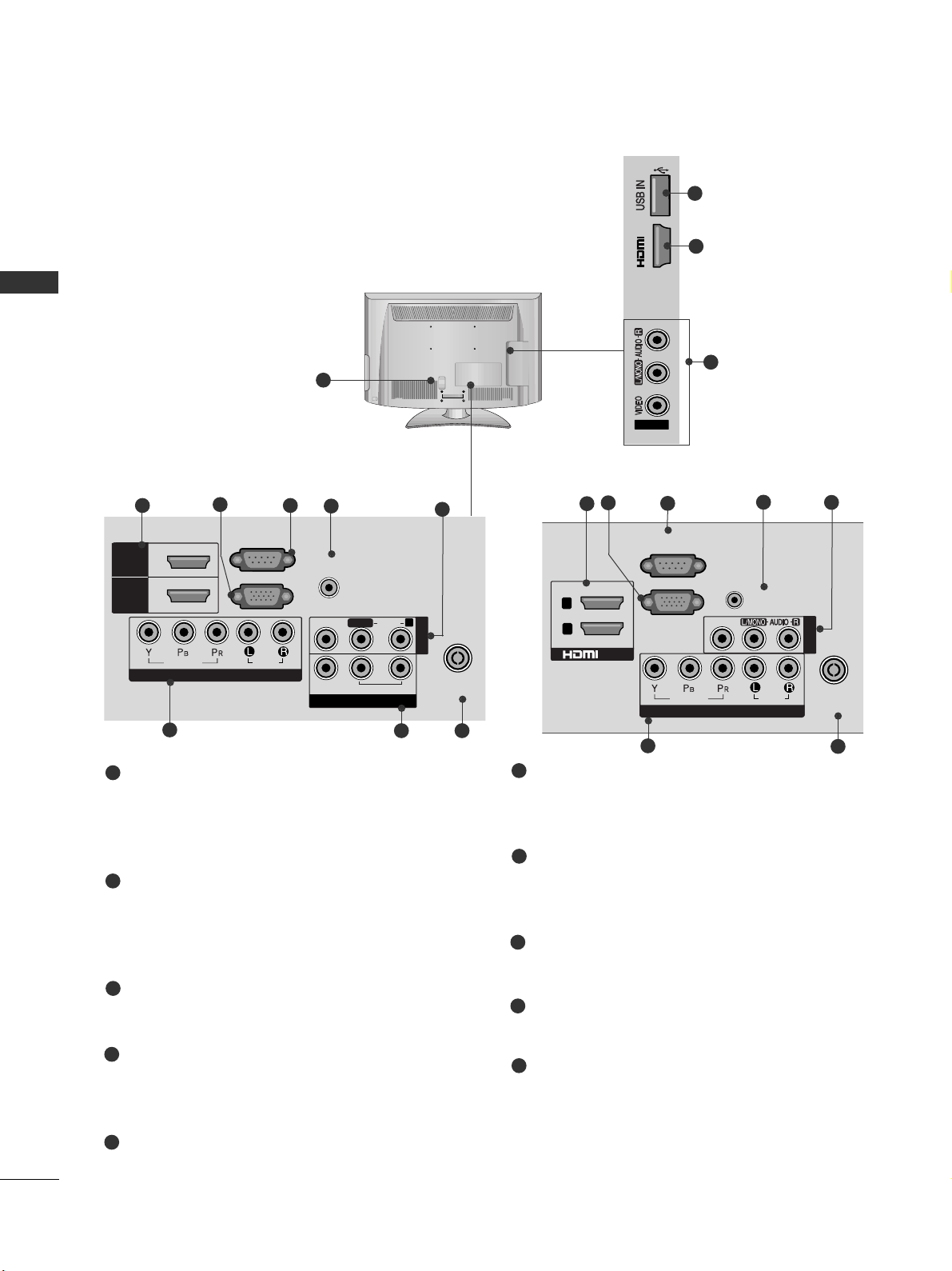
PREPARATION
PREPARATION
■
Image shown may be somewhat different from your TV.
1
Only
32/42LD4**
VIDEO
2
7
8
3
5
6
4
6
Power Cord Socket
This TV operates on an AC power. The voltage is
indicated on the Specifications page. Never
attempt to operate the TV on DC power.
HDMI Input
Connect a HDMI signal to HDMI IN.
Or DVI(VIDEO)signal to HDMI/DVI port with DVI
to HDMI cable.
RGB IN Input
Connect the output from a PC.
RS-232C IN PORT
Connect to the RS-232C port on a PC.
This port is used for Service or Hotel mode.
RGB/DVI Audio Input
Connect the audio from a PC.
Audio/Video Input
Connect audio/video output from an external
device to these jacks.
Component Input
Connect a component video/audio device to
these jacks.
Antenna Input
Connect RF antenna to this jack.
USB IN Input
Connect USB storage device to this jack.
AV Output
Connect second TV or monitor to the AV OUT
socket on the TV.
Variable Audio Output
Connect an external amplifier or add a subwoofer
to your surround sound system.
1
2
3
4
5
7
6
8
9
2
9
COMPONENT IN
AUDIO
VIDEO
ANTENNA
IN
HDMI
/DVI IN
RGB IN
(PC)
RS-232C IN
(CONTROL)
AUDIO IN
(RGB/DVI)
HDMI
1
2
AV OUT
L/L/MONOMONO
R
AUDIOAUDIO
VIDEOVIDEO
VARIABLE AUDIO OUTVARIABLE AUDIO OUT
AV IN1
Only 32LD4**
5
2
7
10
8
Only 42LD4**
3
4
6
10
IN 3
AV IN2
2
1
/DVI IN
RS-232C IN
(CONTROL)
RGB IN
VIDEO
VIDEO
(PC)
COMPONENT IN
AUDIO IN
(RGB/DVI)
AUDIO
AV IN 1
ANTENNA
IN
9
PREPARATION
K
AC-IN
1
MONO)
AUDIO
VIDEO
L - AUDIO OUT - R
2
8
9
3
6
7
4
10
Only
19/22LD345
■
Image shown may be somewhat different from your TV.
AC IN
CABLE MANAGEMENT
1
MONO
AUDIO
VIDEO
L - AUDIO OUT - R
ANTENNA
IN
L( MONO)
R
AUDIO
VIDEOL - AUDIO OUT - R
2
8
9
3
6
7
4
AV IN2
7
10
Only
26/32LD345
Power Cord Socket
This TV operates on an AC power. The voltage is
indicated on the Specifications page. Never
attempt to operate the TV on DC power.
HDMI Input
Connect a HDMI signal to HDMI IN.
Or DVI(VIDEO)signal to HDMI/DVI port with DVI
to HDMI cable.
RGB IN Input
Connect the output from a PC.
RS-232C IN PORT
Connect to the RS-232C port on a PC.
This port is used for Service or Hotel mode.
Audio output
Connect an external amplifier or add a subwoofer
to your surround sound system.
RGB/DVI Audio Input
Connect the audio from a PC.
Audio/Video Input
Connect audio/video output from an external
device to these jacks.
Component Input
Connect a component video/audio device to
these jacks.
Antenna Input
Connect RF antenna to this jack.
USB IN Input
Connect USB storage device to this jack.
1
2
3
4
6
8
7
9
10
5
5
5
AUDIO IN
(RGB/DVI)
L(L(MONO)
AUDIO
AUDIO
R
/DVI IN
RS-232C IN
(CONTROL)
L - AUDIO OUT - R
RGB IN
(PC)
VIDEO
VIDEO
COMPONENT IN
AV IN
ANTENNA
IN
AUDIO IN
(RGB/DVI)
L/L/MONO
AUDIO
AV IN1
R
2
1
RS-232C IN
(CONTROL)
RGB IN
(PC)
L - AUDIO OUT - R
VIDEO
/DVI IN
VIDEO
AUDIO
COMPONENT IN
ANTENNA
IN
10
PREPARATION
PREPARATION
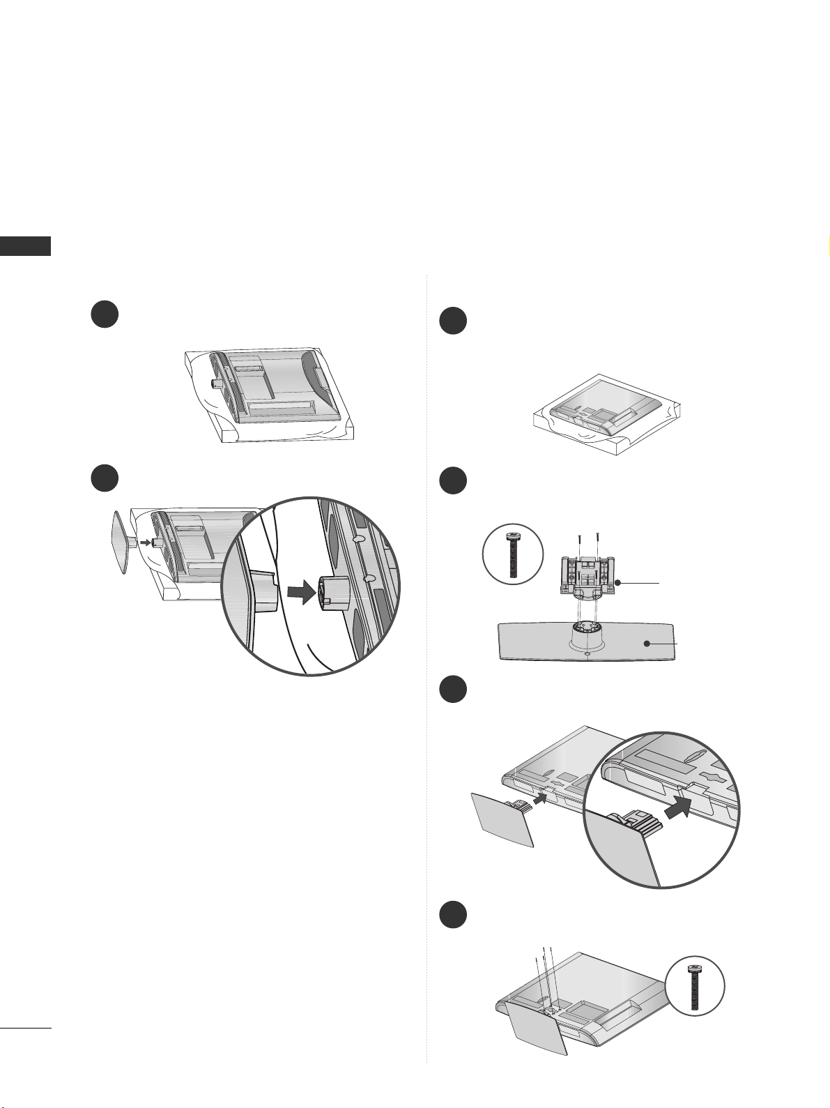
STAND INSTALLATION
■
Image shown may be somewhat different from your TV.
■
When assembling the desk type stand, check whether the bolt is fully tightened. (If not tightened fully, the
product can tilt forward after the product installation.) If you tighten the bolt with excessive force, the bolt can
deviate from abrasion of the tightening part of the bolt.
1
Carefully place the TV screen side down on a cushioned surface to protect the screen from damage.
2
Assemble the TV as shown.
Only 19/22LD3
**
1
3
4
Carefully place the TV screen side down on a
cushioned surface to protect the screen from
damage.
2
Assemble the parts of the
SS ttaann dd BB ooddyy
with
the
SS ttaann dd BB aassee
of the TV.
Assemble the TV as shown.
Fix the 4 bolts securely using the holes in the
back of the TV.
Stand Body
Stand Base
Only 26/32LD3**
M4X20
M4X20
11
PREPARATION
1
2
3
Carefully place the TV screen side down on a cushioned
surface to protect the screen from damage.
Assemble the TV as shown.
Fix the 4 bolts securely using the holes in the
back of the TV.
Only 32/42LD4
**
Only 26/32LD3**, 32/42LD4
**
ATTACHING THE TV TO A DESK
■
Image shown may be somewhat different from your TV.
The TV must be attached to desk so it cannot be pulled
in a forward/backward direction, potentially causing
injury or damaging the product. Use only an attached
screw.
AC IN
CABLE MANAGEMENT
1-Screw (provided as parts of the product)
Desk
Stand
WARNING
!
G
To prevent TV from falling over, the TV should
be securely attached to the floor/wall per installation instructions. Tipping, shaking, or rocking the
machine may cause injury.
SWIVEL STAND
(Except 19/22LD3**)
■
This feature is not available for all models.
■
After installing the TV, you can adjust the TV manually
to the left or right direction by 20 degrees to suit your
viewing position.
POSITIONING YOUR DISPLAY
(Only 19/22LD3**)
■
Image shown may be somewhat different from your
TV.
■
Adjust the position of the panel in various ways for
maximum comfort.
• Tilt range
12
0
3
0
12
PREPARATION
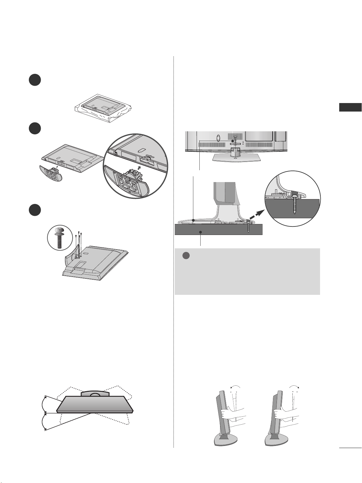
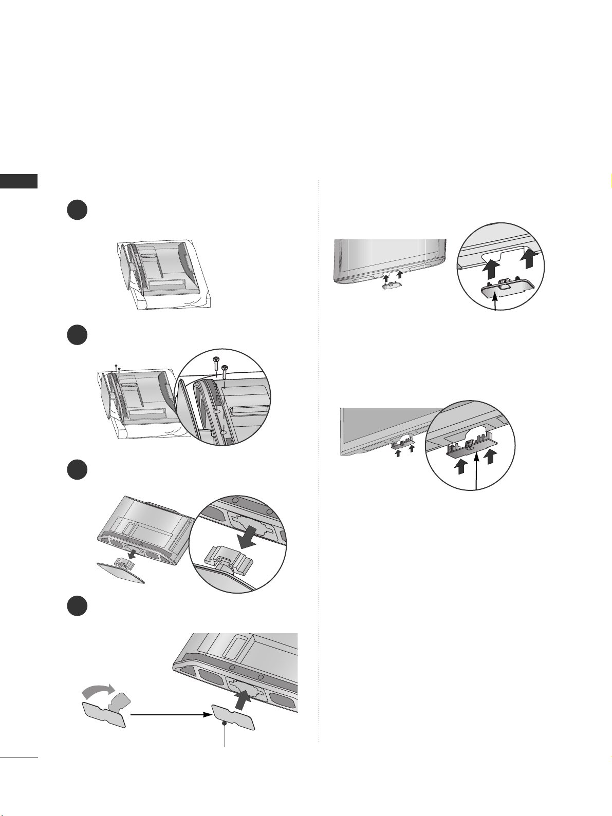
PREPARATION
Insert the
PPrrootteecctt ii oonn CCoovveerr
into the TV until
clicking sound.
■
Image shown may be somewhat different from your TV.
When installing the wall-mounted unit, use the protection cover.
NOT USING THE DESK-TYPE STAND
Loose the bolts from TV.
After removing the protection paper from the
protection cover, adhere it to the TV as shown.
Detach the
SS ttaann dd
from
TT VV
.
2
3
4
Only 19/22LD3
**
1
Carefully place the TV screen side down on a cushioned surface to protect the screen from damage.
Protection Cover
Insert the
PPrrootteecctt ii oonn CCoovveerr
into the TV until clicking
sound.
PPrr oo tt ee cctt iioo nn CCoo vvee rr
Only 26/32LD3
**
Only 32/42LD4
**
PPrr oo tt ee cctt iioo nn CCoo vvee rr

13
PREPARATION
BACK COVER FOR WIRE ARRANGEMENT
■
Image shown may be somewhat different from your TV.
Only 19/22LD3
**
After Connecting the cables as necessary, install
CABLE HOLDER as shown and bundle the cables.
K
AC-IN
K
AC-IN
AC IN
AC IN
AC IN
Connect the cables as necessary.
To connect additional equipment, see the External
Equipment Setup section of the manual.
1
Open the
CCaabbllee MMaann aaggeemmeenn tt CC ll ii pp
as shown
and manage the cables.
2
CCaabb llee MMaann aa ggeemmeenn tt CClliipp
AC IN
Fit the
CCaabbllee MMaann aaggeemmeenn tt CC ll ii pp
as shown.
3
Only 26/32LD3**, 32/42LD4**
NOTE
!
GG
Do not use the
CCaabbllee MMaann aaggeemmeenn tt CC ll ii pp
to lift
the TV.
- If the TV is dropped, you may be injured or the
TV may be damaged.
Cable Holder
14
PREPARATION
PREPARATION
A
The TV can be installed in various ways such as on
a wall, or on a desktop etc.
A
The TV is designed to be mounted horizontally.
EARTHING
Ensure that you connect the earth wire to prevent
possible electric shock. If grounding methods are not
possible, have a qualified electrician install a separate
circuit breaker.
Do not try to earth the TV by connecting it to telephone wires, lightening rods or gas pipes.
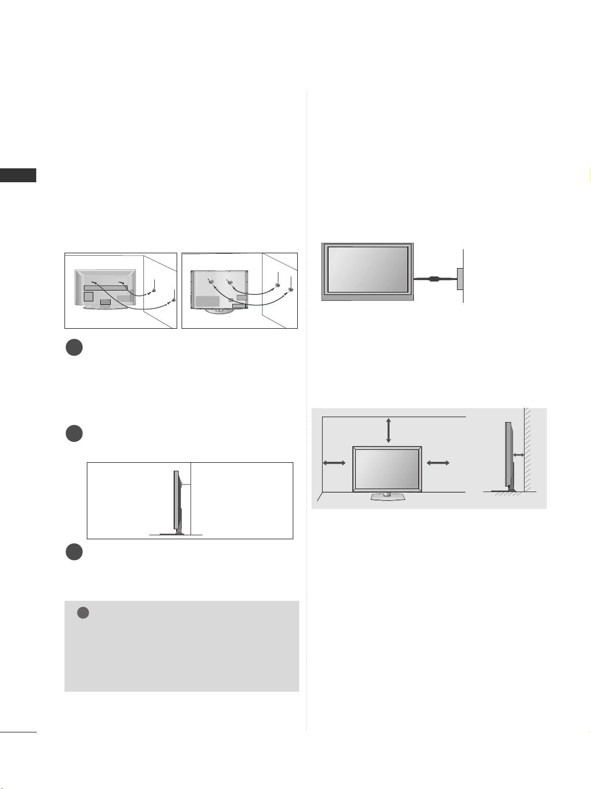
DESKTOP PEDESTAL INSTALLATION
For adequate ventilation allow a clearance of 10 cm
all around the TV.
CAREFUL INSTALLATION ADVICE
A
You should purchase necessary components to fix the TV
safety and secure to the wall on the market.
A
Position the TV close to the wall to avoid the possibility
of it falling when pushed.
A
The instructions shown below are a safer way to set up
the TV, by fixing it to the wall, avoiding the possibility of
it falling forwards if pulled. This will prevent the TV from
falling forward and causing injury. This will also prevent
the TV from damage. Ensure that children do not climb
or hang from the TV.
NOTE
!
G
When moving the TV undo the cords first.
G
Use a platform or cabinet strong and large enough
to support the size and weight of the TV.
G
To use the TV safely make sure that the height of the
bracket on the wall and on the TV is the same.
3
1
2
Use the eye-bolts or TV brackets/bolts to fix the
product to the wall as shown in the picture.
(If your TV has bolts in the eyebolts, loosen then
bolts.)
* Insert the eye-bolts or TV brackets/bolts and tight-
en them securely in the upper holes.
Secure the wall brackets with the bolts on the wall.
Match the height of the bracket that is mounted on
the wall.
3
Use a sturdy rope to tie the product for alignment. It
is safer to tie the rope so it becomes horizontal
between the wall and the product.
2
1
2
1
Power Supply
Circuit breaker
10 c m
10 c m
10 c m
10 c m
15
PREPARATION
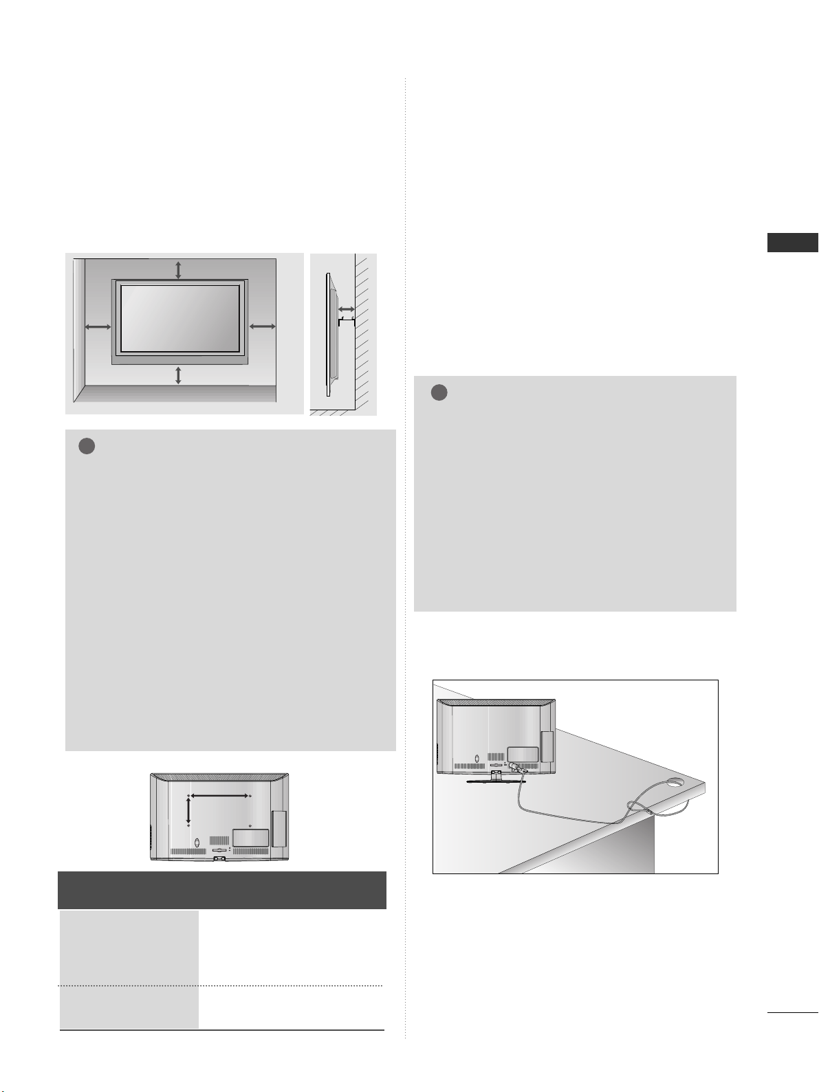
WALL MOUNT: HORIZONTAL INSTALLATION
A
We recommend the use of a LG Brand wall mounting
bracket when mounting the TV to a wall.
A
We recommend that you purchase a wall mounting
bracket which supports VESA standard.
A
LG recommends that wall mounting be performed
by a qualified professional installer.
10 c m
10 c m
10 c m
10 c m
10 c m
NOTE
!
G Should Install wall mount on a solid wall perpendicular to
the floor.
G Should use a special wall mount, if you want to install it to
ceiling or slanted wall.
G The surface that wall mount is to be mounted on should
be of sufficient strength to support the weight of TV set;
e.g. concrete, natural rock, brick and hollow block.
G Installing screw type and length depends on the wall
mount used. Further information, refer to the instructions
included with the mount.
G LG is not liable for any accidents or damage to property or
TV due to incorrect installation:
- Where a non-compliant VESA wall mount is used.
- Incorrect fastening of screws to surface which may cause
TV to fall and cause personal injury.
- Not following the recommended Installation method.
AC IN
CABLE MANAGEMENT
AA
BB
Model
VESA
(A *B)
Standard
Screw
Quantity
19LD3**
22LD3**
26LD3**
32LD3**
32LD4**
42LD4**
100 * 10 0
100 * 10 0
200 * 10 0
200 * 10 0
200 * 10 0
200 * 200
M4
M4
M4
M4
M4
M6
4
4
4
4
4
4
KENSINGTON SECURITY SYSTEM
■
This feature is not available for all models.
■
Image shown may be somewhat different from your TV.
The TV is equipped with a Kensington Security
System connector on the back panel. Connect the
Kensington Security System cable as shown below.
For the detailed installation and use of the
Kensington Security System, refer to the user’s guide
provided with the Kensington Security System.
For further information, contact http://www.kensing-
ton.com, the internet homepage of the Kensington
company. Kensington sells security systems for
expensive electronic equipment such as notebook
PCs and LCD projectors.
AC IN
CABLE MANAGEMENT
NOTE
!
GG
The Kensington Security System is an optional
accessory.
GG
If the TV feels cold to the touch, there may be a
small “flicker” when when it is turned on.
This is normal, there is nothing wrong with TV.
GG
Some minute dot defects may be visible on the
screen, appearing as tiny red, green, or blue
spots. However, they have no adverse effect on
the monitor's performance.
GG
Avoid touching the LCD screen or holding your finger(s)
against it for long periods of time.
Doing so may produce some temporary distortion effects on the screen.
AC IN
CABLE MANAGEMENT
16
PREPARATION
PREPARATION
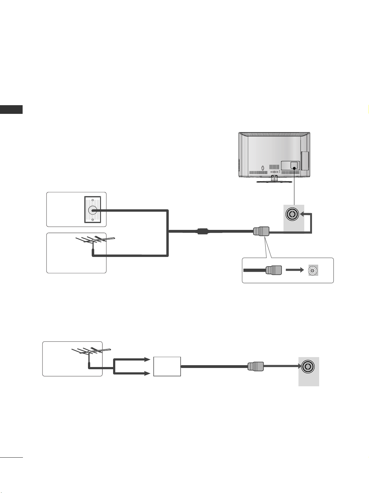
ANTENNA CONNECTION
■
For optimum picture quality, adjust antenna direction.
■
An antenna cable and converter are not supplied.
■
To prevent damage do not connect to the mains outlet until all connections are made between the devices.
Multi-family Dwellings/Apartments
(Connect to wall antenna socket)
Single-family Dwellings /Houses
(Connect to wall jack for outdoor antenna)
Outdoor
Antenna
(VHF, UHF)
Wall
Antenna
Socket
RF Coaxial Wire (75 Ω)
Antenna
UHF
Signal
Amplifier
VHF
■
In poor signal areas, to achieve better picture quality it may be necessary to install a signal amplifier to the
antenna as shown above.
■
If signal needs to be split for two TVs, use an antenna signal splitter for connection.
ANTENNA
IN
ANTENNA
IN
17
EXTERNAL EQUIPMENT SETUP
EXTERNAL EQUIPMENT SETUP
HD RECEIVER SETUP
■
To avoid damaging any equipment, never plug in any power cords until you have finished connecting all equipment.
■
This section on External Equipment Setup mainly uses diagrams for the 26/32LD33* models.
■
Image shown may be somewhat different from your TV.
Connecting with a component cable
Signal
480i / 576i
480p / 576p
720p / 1080i
10 8 0 p
Component
O
O
O
O
(50 Hz / 60 Hz only)
HDMI
X
O
O
O
(24 Hz / 30 Hz / 50 Hz / 60 Hz)
Connect the video outputs (Y, PB, PR
)
of the digital set
top box to the
CCOO MM PPOONNEENNTT IINN VVIIDD EEOO
jacks on the
TV.
Connect the audio output of the digital set-top box to
the
CCOO MM PPOONNEENNTT II NN AAUU DDIIOO
jacks on the TV.
Turn on the digital set-top box.
(
Refer to the owner’s manual for the digital set-top box.
)
Select
CCoommppoo nneenntt
input source using the
II NNPPUUTT
button on the remote control.
2
3
4
1
1
ANTENNA
IN
/DVI IN
COMPONENT IN
AUDIO
VIDEO
1
2

18
EXTERNAL EQUIPMENT SETUP
EXTERNAL EQUIPMENT SETUP
EXTERNAL EQUIPMENT SETUP
Connecting a set-top box with an HDMI cable
Connect the digital set-top box to
HH DDMMII//DDVV II IINN 11
,
HH DDMMII//DDVV II IINN 22
(Except 19/22LD3**)
or
HH DDMM II IINN
33
(Only 32/42LD4**)
jack on the TV.
Turn on the digital set-top box.
(
Refer to the owner’s manual for the digital set-top box.
)
Select
HH DD MM II 11, HH DD MM II 22
(Except 19/22LD3**)
or
HH DD MM II 33
(Only 32/42LD4**)
input source using the
II NNPPUUTT
button on the remote control.
2
3
1
GG
Check that your HDMI cable is High Speed HDMI Cable.
If the HDMI cables are not High Speed HDMI Cable,
flickering or no screen display can result. Please use the
High Speed HDMI Cable.
GG
We recommed less than 10m for HDMI cable, and recommend to use amplifier or repeater for more than that.
NOTE
!
AUDIO
(RGB/D
RGB IN
(PC)
COMPONENT I
VIDEO
LYP
BPR
A
VIDEO
/MONO
1
2
/DVI IN
1

19
EXTERNAL EQUIPMENT SETUP
Connecting with an HDMI to DVI cable
Connect the digital set-top box to
HH DDMMII//DDVV II IINN 11
jack on the TV.
Connect the audio output of the digital set-top box to
the
AA UUDDIIOO II NN ((RRGGBB //DDVVII ))
jack on the TV.
Turn on the digital set-top box. (Refer to the owner’s
manual for the digital set-top box.
)
Select
HH DD MM II 11
input source using the
II NNPP UU TT
button
on the remote control.
2
3
4
1
RGB IN
(PC)
COMPONENT IN
VIDEO
LYP
BPR
AUDIO
VIDEO
AUD
/MONO
1
AUDIO IN
(RGB/DVI)
/DVI IN
2
1
2

20
EXTERNAL EQUIPMENT SETUP
EXTERNAL EQUIPMENT SETUP
DVD SETUP
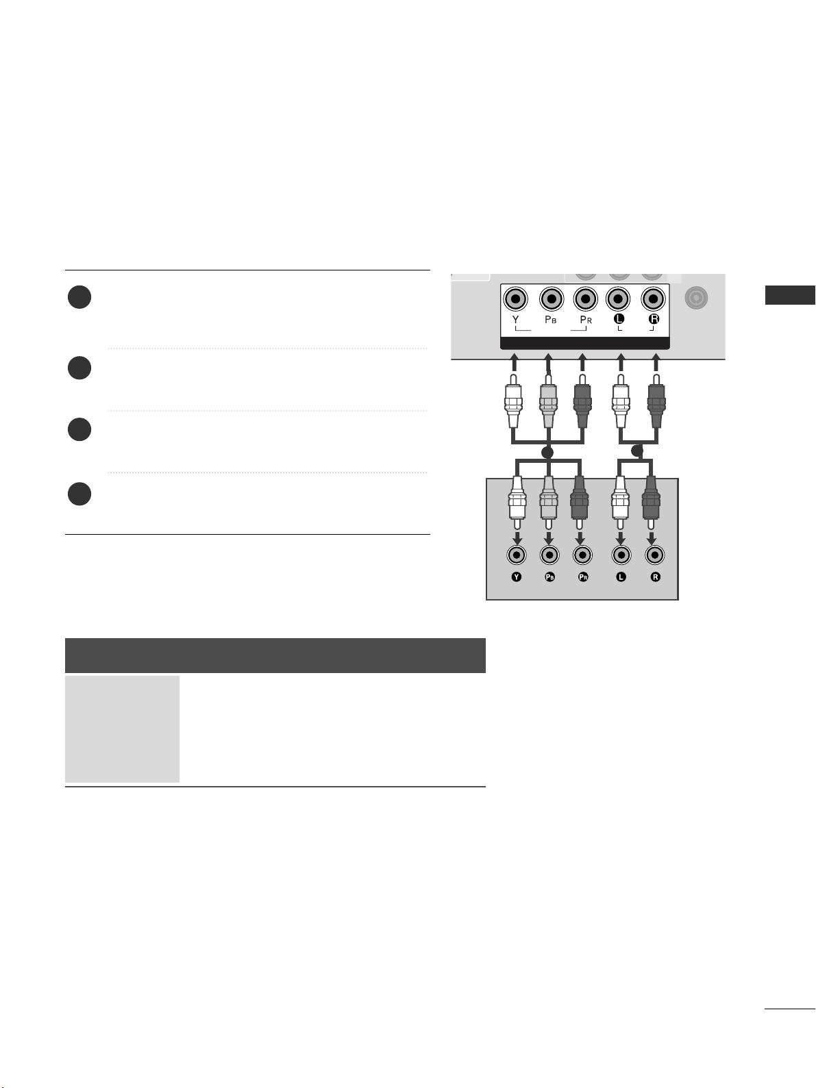
Connecting with a component cable
Component Input ports
To achieve better picture quality, connect a DVD player to the component input ports as shown below.
Component ports on the TV
YPB PR
Video output ports
on DVD player
Y
Y
Y
Y
P
B
B-Y
Cb
Pb
PR
R-Y
Cr
Pr
Connect the video outputs (Y, PB, PR
)
of the DVD to the
CCOO MM PPOONNEENNTT II NN VVII DDEEOO
jacks on the TV.
Connect the audio outputs of the DVD to the
CCOO MM PPOONNEENNTT II NN AAUU DDIIOO
jacks on the TV.
Turn on the DVD player, insert a DVD.
Select
CCoommppoo nneenntt
input source using the
II NNPP UU TT
button on the remote control.
Refer to the DVD player's manual for operating instructions.
2
3
4
5
1
1
ANTENNA
IN
/DVI IN
COMPONENT IN
AUDIO
VIDEO
1
2
21
EXTERNAL EQUIPMENT SETUP
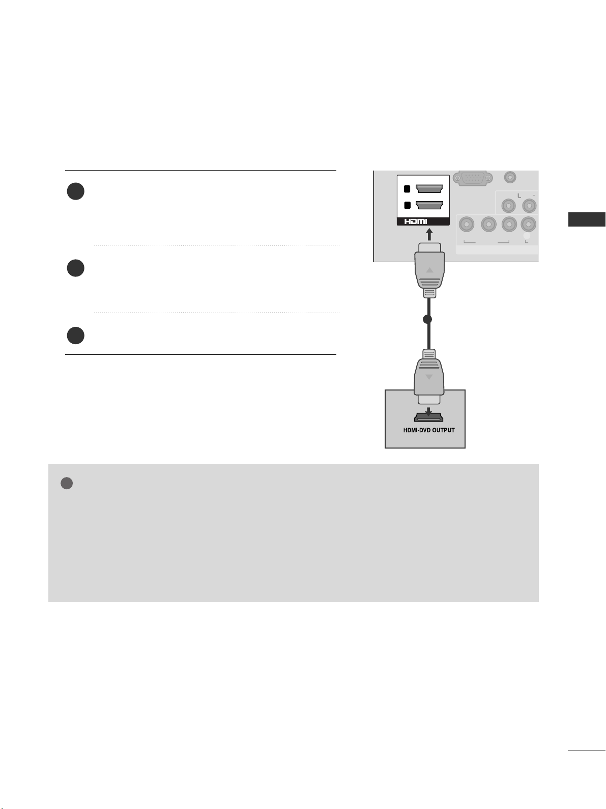
Connecting the HDMI cable
Connect the HDMI output of the DVD to the
HH DDMMII//DDVV II IINN 11,HH DDMMII//DDVV II IINN 22
(Except
19/22LD3**)
or
HH DDMMII IINN 33
(Only 32/42LD4**)
jack on
the TV.
Select
HH DD MM II 11, HH DD MM II 22
(Except 19/22LD3**)
or
HH DD MM II 33
(Only 32/42LD4**)
input source using the
II NNPPUUTT
button on the remote control.
Refer to the DVD player's manual for operating instructions.
2
3
1
GG
The TV can receive video and audio signals simultaneously when using a HDMI cable.
GG
If the DVD does not support Auto HDMI, you must set the output resolution appropriately.
GG
Check that your HDMI cable is High Speed HDMI Cable.
If the HDMI cables are not High Speed HDMI Cable, flickering or no screen display can result.
Please use the High Speed HDMI Cable.
GG
We recommed less than 10m for HDMI cable, and recommend to use amplifier or repeater for
more than that.
NOTE
!
AUDIO I
(RGB/DV
RGB IN
(PC)
COMPONENT IN
VIDEO
LYP
BPR
AUD
VIDEO
AU
/MONO
1
2
L( MONO)
R
AUDIO
VIDEO
/DVI IN
1
22
EXTERNAL EQUIPMENT SETUP
EXTERNAL EQUIPMENT SETUP
VCR SETUP
■
To avoid picture noise (interference), allow adequate distance between the VCR and TV.
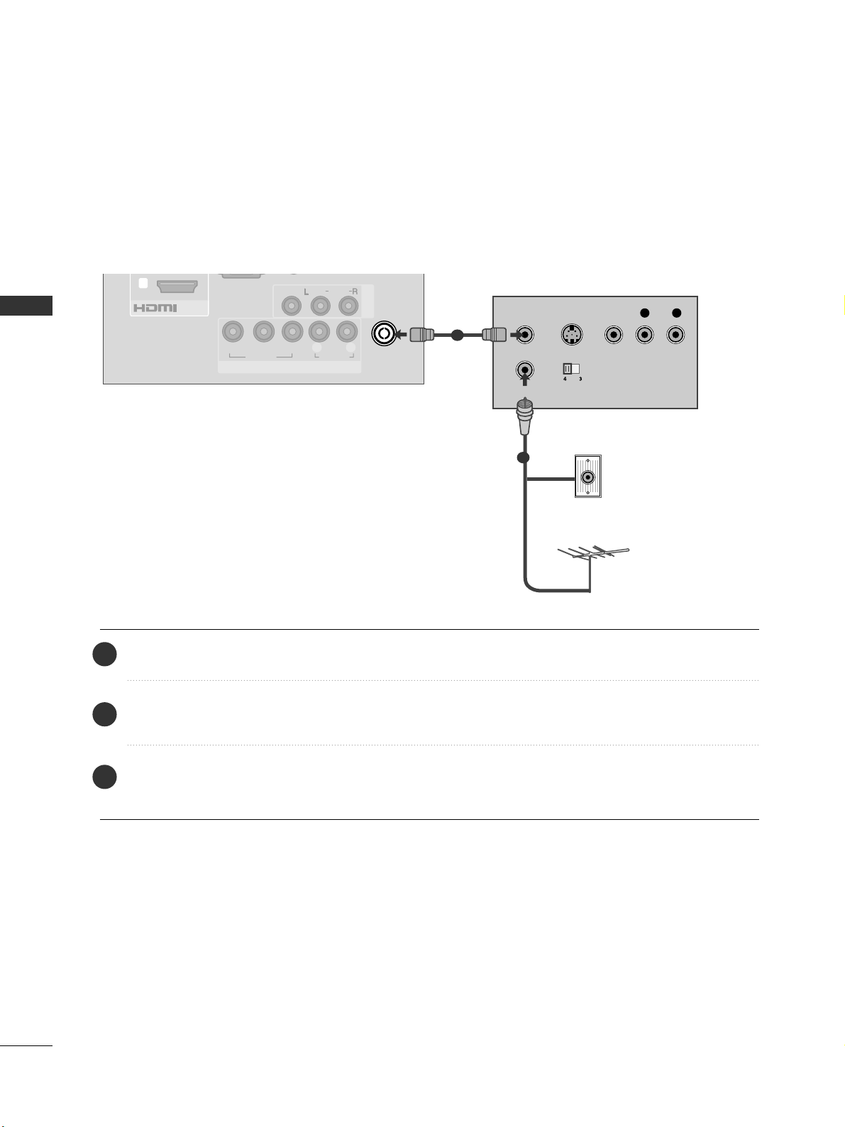
Connecting with a RF Cable
Connect the
AA NNTT OOUUTT
socket of the VCR to the
AA NNTTEENNNNAA IINN
socket on the TV.
Connect the antenna cable to the
AA NNTT IINN
socket of the VCR.
Press the
PP LLAAYY
button on the VCR and match the appropriate channel between the TV and VCR for
viewing.
2
3
1
Wall Jack
Antenna
()
RGB IN
(PC)
COMPONENT IN
VIDEO
LYP
BPR
R
AUDIO
AV IN1
VIDEO
AUDIO
/MONO
/DVI IN
1
ANTENNA
IN
OUTPUT
SWITCH
ANT IN
R
S-VIDEO VIDEO
ANT OUT
L
1
2

23
EXTERNAL EQUIPMENT SETUP
Connecting with a RCA cable
Connect the
AA UU DDIIOO/VV II DDEEOO
jacks between TV and
VCR. Match the jack colours (Video = yellow, Audio Left
= white, and Audio Right = red)
Insert a video tape into the VCR and press PLAY on
the VCR. (Refer to the VCR owner’s manual.
)
Select
AAVV 11
input source using the
II NNPPUUTT
button on
the remote control.
If connected to
AA VV IINN22
, select
AA VV22
input source.
1
2
3
GG
If you have a mono VCR, connect the audio cable from the
VCR to the
AA UUDDII OO LL //MMOO NNOO
jack of the TV.
NOTE
!
(RGB/DVI)
RGB IN
(PC)
COMPONENT IN
VIDEO
LYP
BPR
R
AUDIO
ANTENNA
IN
L(L(MONO)MONO)
R
AUDIOAUDIO
VIDEOVIDEO
AV IN
L
R
S-VIDEO
VIDEO
OUTPUT
SWITCH
ANT IN
ANT OUT
L( MONO)
R
AUDIO
VIDEO
USB IN SETUP (Except 19/22/26/32LD33*)
■
Image shown may be somewhat different from your TV.
ANTENNA
IN
L( MONO)
R
AUDIO
VIDEO
Connect the USB device to the
UU SSBB IINN
jacks on the side of TV.
After connecting the
UU SSBB IINN
jacks, you use the
UU SS BB
function. (
GG
pp..5533
)
2
1
1
1
24
EXTERNAL EQUIPMENT SETUP
EXTERNAL EQUIPMENT SETUP
EXTERNAL EQUIPMENT SETUP
OTHER A/V SOURCE SETUP
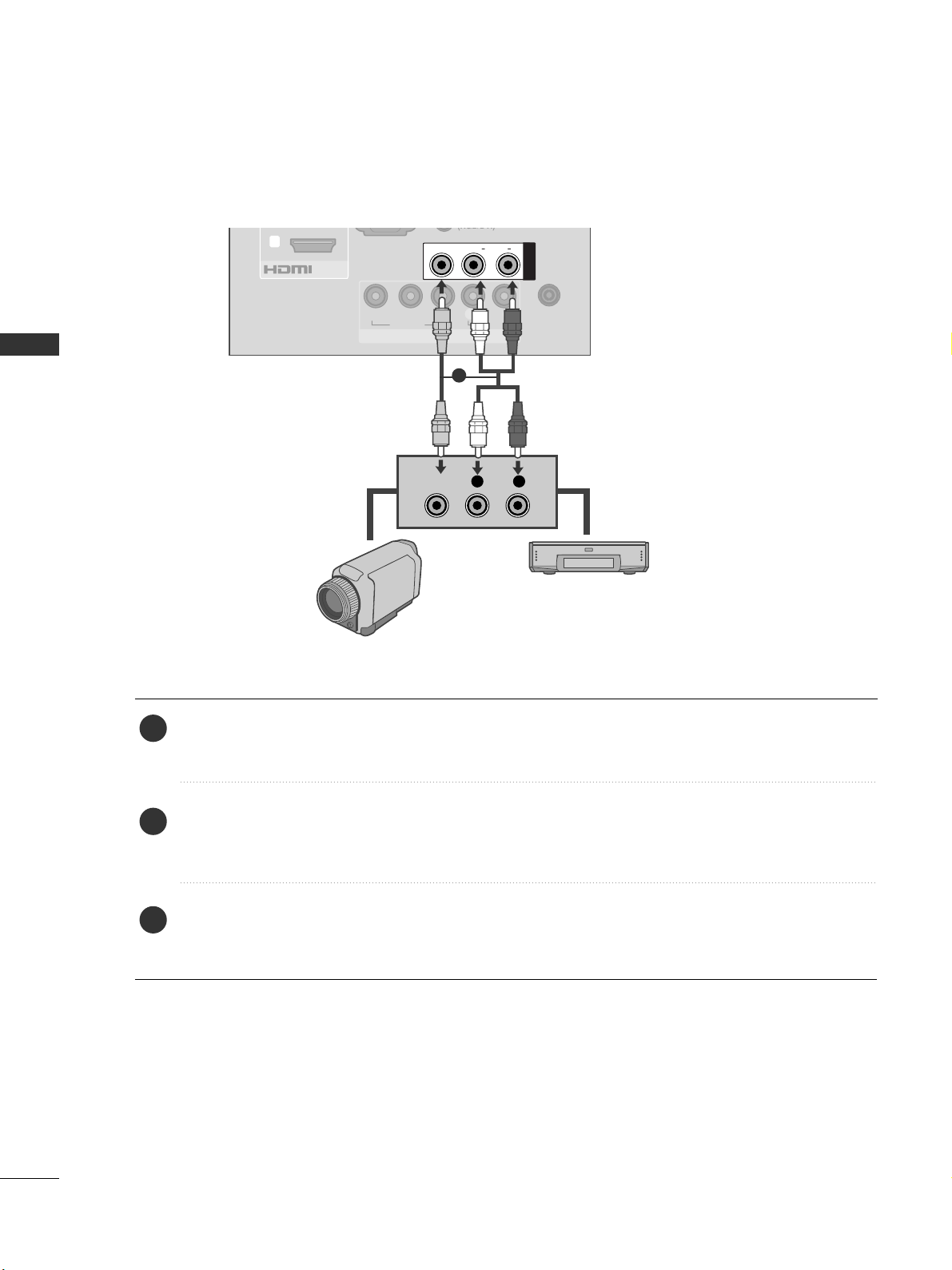
Connect the
AA UU DDIIOO/VV II DDEEOO
jacks between TV and external equipment. Match the jack colours
.
(
Video = yellow, Audio Left = white, and Audio Right = red
)
Select
AAVV 11
input source with using the
II NNPP UU TT
button on the remote control.
If connected to
AA VV IINN22
, select
AA VV 22
input source.
Operate the corresponding external equipment.
Refer to external equipment operating guide.
1
2
3
(RGB/DVI)
RGB IN
(PC)
COMPONENT IN
VIDEO
LYP
BPR
R
AUDIO
ANTENNA
IN
/DVI IN
1
L(L(MONO)MONO)
R
AUDIOAUDIO
VIDEOVIDEO
AV IN
L R
VIDEO
Camcorder
Video Game Set
1
25
EXTERNAL EQUIPMENT SETUP
EXTERNAL STEREO SETUP (Only 32LD4** or 19/22/26/32LD345)
AV IN 1
VIDEO
AUDIO
/MONO
ANTENNA
IN
AV OUT
VARIABLE AUDIO OUTVARIABLE AUDIO OUT
L R
AUDIO
VARIABLE AUDIO OUT
GG
When connecting with external audio equipments, such as
amplifiers or speakers, please turn the TV speakers off.
(
GG
pp ..88 66
)
GG
Select
VV aarriiaabb ll ee OOuutt
in
AA UU DDIIOO
menu to connect the
VV AA RR IIAABBLLEE AA UUDDII OO OOUUTT
jacks.(
GG
pp ..88 77
)
GG
This function works in following mode : RF, AV,
Component, RGB, HDMI, USB.
NOTE
!
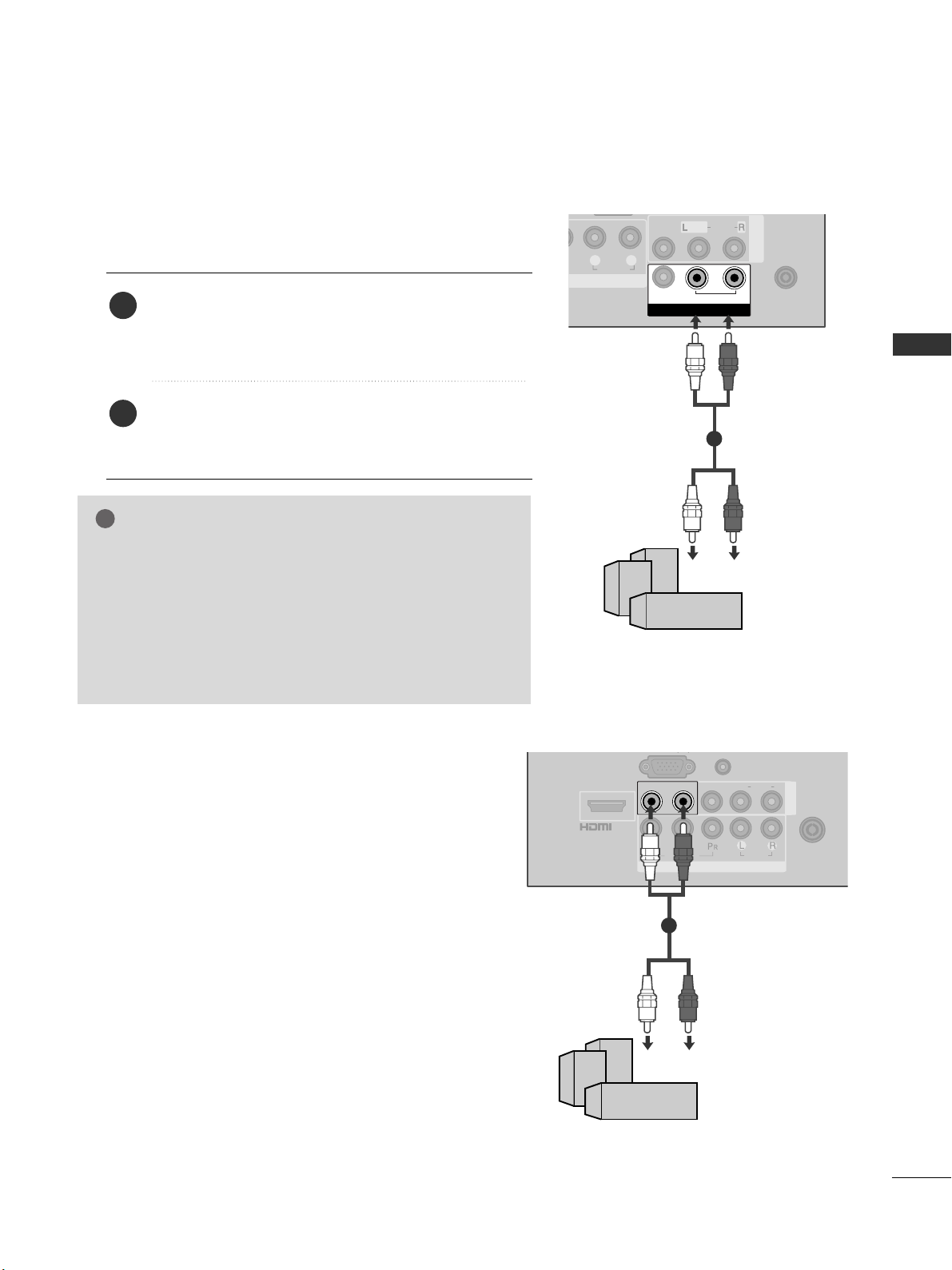
Use to connected either an external amplifier, or add a sub-woofer
to your surround sound system.
Connect the input jack of the stereo amplifier to the
VV AARR IIAABBLLEE AAUUDD IIOO OOUUTT
(Only 32LD4**) or
AA UUDDII OO OOUUTT
(Only 19/22/26/32LD345) jacks on
the TV.
Set up your speakers through your analog stereo
amplifier, according to the instructions provided with
the amplifier.
2
1
11
COMPONENT IN
AUDIO
VIDEO
ANTENNA
IN
L(L(MONO)MONO)
R
AUDIOAUDIO
VIDEOVIDEOL - AUDIO OUT - RL - AUDIO OUT - R
AV IN
AUDIO IN
(RGB/DVI)
/DVI IN
()
11
or

26
EXTERNAL EQUIPMENT SETUP
EXTERNAL EQUIPMENT SETUP
PC SETUP
This TV provides Plug and Play capability, meaning that the PC
adjusts automatically to the TV's settings.
Connecting with a D-sub 15 pin cable
USB IN
SERVICE ONLY
COMPONENT IN
VIDEO
LYP
BPR
R
AUDIO
AV IN1
VIDEO
AUDIO
/MONO
ANTENNA
IN
/DVI IN
1
2
RS-232C IN
(CONTROL)
RGB IN
(PC)
AUDIO IN
(RGB/DVI)
RGB OUTPUT
AUDIO
1 2
4
Connect the RGB output of the PC to the
RRGG BB IINN
(( PP CC ))
jack on the TV.
Connect the PC audio output to the
AA UUDDII OO IINN
(( RR GGBB//DDVVII ))
jack on the TV.
Turn on the TV and the PC.
Select
RRGGBB
input source using the
II NNPP UU TT
button on
the remote control.
2
3
1
AV OUTPUT SETUP (Only 32LD4**)
The TV has a special signal output capability which allows you
to hook up the second TV or monitor.
1
ANTENNA
IN
AV OUT
VARIABLE AUDIO OUTVARIABLE AUDIO OUT
L R
S-VIDEO
VIDEO
Connect the second TV or monitor to the TV’s
AAVV OOUUTT
jacks.
See the Operating Manual of the second TV or monitor
for further details regarding that device’s input settings.
GG
Component, RGB, HDMI input sources cannot be used for
AV out.
GG
We recommend to use the AV OUT jacks for VCR recording.
NOTE
!
2
1
1

27
EXTERNAL EQUIPMENT SETUP
NOTE
!
GG
Avoid keeping a fixed image on the TV ’s screen
for prolonged periods of time.The fixed image
may become permanently imprinted on the
screen;use a screen saver when possible.
GG
There may be interference relating to resolution,
vertical pattern, contrast or brightness in PC
mode. Change the PC mode to another resolution or change the refresh rate to another rate
or adjust the brightness and contrast on the
menu until the picture is clear. If the refresh rate
of the PC graphic card can not be changed,
change the PC graphic card or consult the manufacturer of the PC graphic card.
GG
The synchronization input waveform for
Horizontal and Vertical frequencies are separate.
GG
If the resolution of PC is over SXGA, there will
be no picture on the TV.(only HD Models)
GG
Connect the audio cable from the PC to the
Audio input on the TV.(Audio cables are not
included with the TV).
GG
If you use too long an RGB-PC cable, there may
be interference on the screen. We recommend
using under 5m of the cable. This provides the
best picture quality.
GG
We recommend using 1360 x 768, 60 Hz (Only
19/22/26/32LD3**), 1920 x 1080, 60 Hz
(Only 32/42LD4**) for the PC mode, these
should provide the best picture quality.
GG
HDMI mode supports PCM audio format only.
GG
If the Audio setting is set to
Dolby/DTS/Bitstream in some DVDP/STB, make
sure to change the setting to PCM.
Resolution
720x480
720x576
1280x720
1920x1080i
1920x1080p
HDMI-DTV mode
Horizontal Vertical
Frequency(kHz) Frequency(Hz)
31.47 59.94
31.50 60.00
31.25 50.00
44.96 59.94
45.00 60.00
37.50 50.00
33.75 60.00
33.72 59.94
28.125 50.00
67.432 59.94
67.5 60
56.250 50
27 24
33.75 30
Resolution
640x350
720x400
640x480
800x600
1024x768
1280x768
1360x768
1280x1024
1920x1080
RGB-PC mode
Horizontal Vertical
Frequency(kHz) Frequency(Hz)
31.468 70.09
31.469 70.09
31.469 59.94
37.879 60.317
48.363 60.004
47.776 59.87
47.720 59 .799
63.668 59.895
66.587 59.934
Only 32/42LD4**
Supported Display Resolution

28
EXTERNAL EQUIPMENT SETUP
EXTERNAL EQUIPMENT SETUP
EXTERNAL EQUIPMENT SETUP
Screen Setup for PC mode
Returns Position, Size and Phase to the factory default settings.
This function works in the following mode : RGB[PC], Component(except 480i, 576i).
Screen Reset
To Set
Auto Config.
Screen
Move
Prev.
Resolution
Position
Size
Phase
Reset
G
OK
Move
• Contrast 90
• Brightness 50
• Sharpness 60
• Colour 60
• Tint 0
• Advanced Control
• Picture Reset
Screen
PICTURE
RG
E
Screen
Yes No
1
MENU
Select
PP IICC TTUURREE
.
Select
SS cc rreeeenn
.
3
Select
RReesseett
.
2
OK
OK
Select
YY eess
.
Run
RReesseett
.
4
OK
5
OK
• Press the
MMEENN UU // EEXX IITT
button to return to normal TV viewing.
• Press the
BBAACC KK
button to move to the previous menu screen.
 Loading...