

LG Electronics 37LD325H, 37LD320H, 32LD320H, 32LD325H, 26LD320H User Manual
...
26LD320H 32LD320H 37LD320H 42LD320H
32LD325H 37LD325H
Lodging Guest Interactive Pro:Centric™ TVs
Commercial Mode Setup Guide
Note: Selected features shown in this guide may not be available on all models.
EXPERIENCED INSTALLER
© Copyright 2010, LG Electronics U.S.A., Inc.
Commercial Mode Setup
pages 12 – 13
Cloning Information
pages 27 – 32
b-LAN™ Setup & Overview
page 39
P/N: 206-4163 (Rev B)
WARNING
RISK OF ELECTRIC SHOCK
DO NOT OPEN
For Customer Support/Service, please call:
1-888-865-3026
The latest product information and documentation is
available online at:
www.LGsolutions.com/products
MODEL and SERIAL NUMBER
The model and serial numbers of this TV are located on the
back of the cabinet. For future reference, LG suggests that
you record those numbers here:
Model No._________________Serial No. _______________
WARNING:
TO REDUCE THE RISK OF ELECTRIC SHOCK DO NOT REMOVE COVER (OR BACK). NO USERSERVICEABLE PARTS INSIDE. REFER TO QUALIFIED SERVICE PERSONNEL.
The lightning flash with arrowhead symbol, within an equilateral triangle, is intended to alert the user to
the presence of uninsulated “dangerous voltage” within the product’s enclosure that may be of sufficient
magnitude to constitute a risk of electric shock to persons.
The exclamation point within an equilateral triangle is intended to alert the user to the presence of important
operating and maintenance (servicing) instructions in the literature accompanying the appliance.
WARNING:
TO PREVENT FIRE OR SHOCK HAZARDS, DO NOT EXPOSE THIS PRODUCT TO RAIN OR MOISTURE.
POWER CORD POLARIZATION:
This product is equipped with a 3-wire grounding-type alternating current power plug. This plug will fit into the power
outlet only one way. This is a safety feature. If you are unable to insert the plug fully into the outlet, contact your electrician to replace your obsolete outlet. Do not defeat the safety purpose of the 3-wire grounding-type plug.
NOTE TO CABLE/TV INSTALLER:
This reminder is provided to call the cable TV system installer’s attention to Article 820-40 of the National Electric
Code (U.S.A.). The code provides guidelines for proper grounding and, in particular, specifies that the cable ground
shall be connected to the grounding system of the building, as close to the point of the cable entry as practical.
REGULATORY INFORMATION:
This equipment has been tested and found to comply with the limits for a Class B digital device, pursuant to Part 15 of
the FCC Rules. These limits are designed to provide reasonable protection against harmful interference when the
equipment is operated in a residential installation. This equipment generates, uses and can radiate radio frequency
energy and, if not installed and used in accordance with the instruction manual, may cause harmful interference to radio
communications. However, there is no guarantee that interference will not occur in a particular installation. If this equipment does cause harmful interference to radio or television reception, which can be determined by turning the equipment off and on, the user is encouraged to try to correct the interference by one or more of the following measures:
• Reorient or relocate the receiving antenna.
• Increase the separation between the equipment and receiver.
• Connect the equipment to an outlet on a circuit different from that to which the receiver is connected.
• Consult the dealer or an experienced radio/TV technician for help.
CAUTION:
Do not attempt to modify this product in any way without written authorization from LG Electronics U.S.A., Inc.
Unauthorized modification could void the user’s authority to operate this product.
COMPLIANCE:
The responsible party for this product’s compliance is: LG Electronics U.S.A., Inc.
1000 Sylvan Avenue, Englewood Cliffs, NJ 07632, USA • Phone: 1-201-816-2000
Marketed and Distributed in the United States by LG Electronics U.S.A., Inc.
1000 Sylvan Avenue, Englewood Cliffs, NJ 07632
2
© Copyright 2010, LG Electronics U.S.A., Inc.
206-4163

IMPORTANT SAFETY INSTRUCTIONS
PORTABLE CART WARNING
1. Read these instructions.
2. Keep these instructions.
3. Heed all warnings.
4. Follow all instructions.
5. Do not use this apparatus near water.
6. Clean only with dry cloth.
7. Do not block any ventilation openings. Install in accordance with the manufacturer’s instructions.
8. Do not install near any heat sources, such as radiators,
heat registers, stoves, or other apparatus (including
amplifiers) that produce heat.
9. Do not defeat the safety purpose of the polarized or
grounding-type plug. A polarized plug has two blades
with one wider than the other. A grounding-type plug
has two blades and a third grounding prong. The wide
blade or the third prong are provided for your safety. If
the provided plug does not fit into your outlet, consult
an electrician for replacement of the obsolete outlet.
10. Protect the power cord from being walked on or pinched,
particularly at plugs, convenience receptacles, and the
point where it exits from the apparatus.
11. Only use attachments/accessories specified by the manufacturer.
12. Use only with the cart, stand, tripod, bracket, or table
specified by the manufacturer or sold with the apparatus. When a cart is used, use caution when moving the
cart/apparatus combination in order to avoid injury from
tip-over.
13.
Refer all servicing to qualifi ed service personnel.
Servicing is required when the apparatus has been damaged in any way, such as power-supply cord or plug is
damaged, liquid has been spilled or objects have fallen
into the apparatus, the apparatus has been exposed to
rain or moisture, does not operate normally, or has been
dropped.
14. Never touch this apparatus or antenna during a thunder or
lighting storm.
15. When mounting a TV on the wall, make sure not to install
the TV by the hanging power and signal cables on the back
of the TV.
16. Do not allow an impact shock or any objects to fall into the
product, and do not drop objects onto the screen.
17. Power Cord
Caution: It is recommended that appliances be placed
upon a dedicated circuit; that is, a single outlet circuit
which powers only that appliance and has no additional
outlets or branch circuits. Check the specification page
of the Owner’s Manual to be certain.
Periodically examine the cord of your appliance, and if its
appearance indicates damage or deterioration, unplug it,
discontinue use of the appliance, and have the cord replaced
with an exact replacement part by an authorized servicer.
Protect the power cord from physical or mechanical abuse,
such as twisting, kinking, or pinching or being closed in a
door or walked upon. Pay particular attention to plugs, wall
outlets, and the point where the cord exits the appliance.
Do not use a damaged or loose power cord. Be sure to grasp
the plug when unplugging the power cord. Do not pull on the
power cord to unplug the TV.
18. Overloading
Do not connect too many appliances to the same AC power
outlet as this could result in fire or electric shock. Do not
overload wall outlets. Overloaded wall outlets, loose or damaged wall outlets, extension cords, frayed power cords, or
damaged or cracked wire insulation are dangerous. Any of
these conditions could result in fi re or electric shock.
19. Outdoor Use/Wet Location
Warning: To reduce the risk of fi re or electrical
shock, do not expose this product to rain,
moisture or other liquids.
Do not touch the TV with wet hands. Do not install this prod-
uct near fl ammable objects such as gasoline or candles or
expose the TV to direct air conditioning.
Do not expose to dripping or splashing and do not place
objects fi lled with liquids, such as vases, cups, etc., on or over
the apparatus (e.g., on shelves above the unit).
20. Grounding
Ensure that you connect the earth ground wire to prevent
possible electric shock (i.e., a TV with a three-prong grounded AC plug must be connected to a three-prong grounded
AC outlet). If grounding methods are not possible, have a
qualified electrician install a separate circuit breaker. Do not
try to ground the unit by connecting it to telephone wires,
lightening rods, or gas pipes.
21. Disconnect Device
The mains plug is the disconnecting device. The plug must
remain readily operable.
As long as this unit is connected to the AC wall outlet, it is
not disconnected from the AC power source even if you turn
off this unit by SWITCH.
(Continued on next page)
206-4163
3
IMPORTANT SAFETY INSTRUCTIONS
(Continued from previous page)
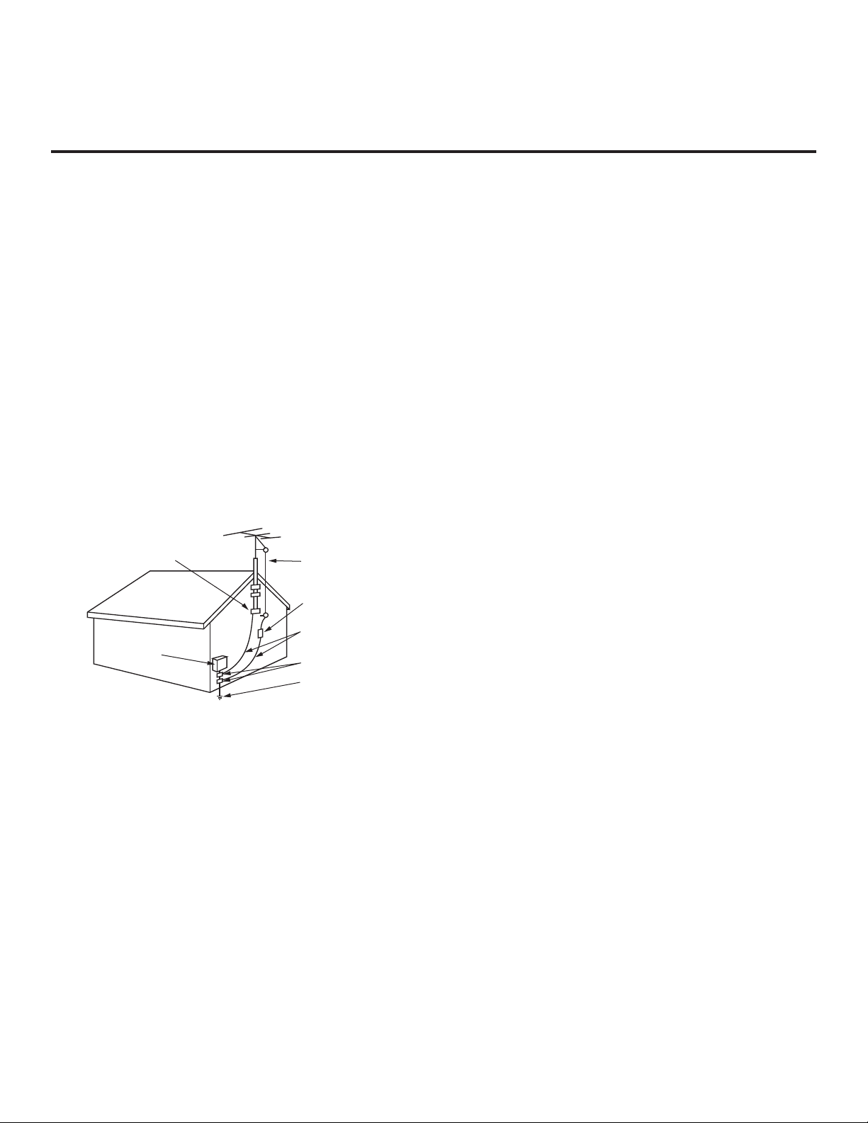
22. Outdoor Antenna Grounding
If an outside antenna or cable system is connected to the
product, follow the precautions below.
An outdoor antenna system should not be located in the
vicinity of overhead power lines or other electric light or
power circuits or where it can come into contact with such
power lines or circuits as death or serious injury can occur.
Be sure the antenna system is grounded so as to provide
some protection against voltage surges and built-up static
charges.
Article 810 of the National Electrical Code (NEC) in the
U.S.A. provides information with respect to proper grounding
of the mast and supporting structure, grounding of the leadin wire to an antenna-discharge unit, size of grounding conductors, location of antenna-discharge unit, connection to
grounding electrodes, and requirements for the grounding
electrode.
Antenna Grounding According to NEC, ANSI/NFPA 70
Ground Clamp
Electric Service
Equipment
Antenna Lead in Wire
Antenna Discharge Unit
(NEC Section 810-20)
Grounding Conductor
(NEC Section 810-21)
Ground Clamps
Power Service Grounding
Electrode System (NEC
Art 250, Part H)
23. Cleaning
When cleaning, unplug the power cord and rub gently with a
soft cloth to prevent scratching. Do not spray water or other
liquids directly on the TV as electric shock may occur. Do not
clean with chemicals such as alcohol, thinners or benzene.
27. If you smell smoke or other odors coming from the TV or
hear strange sounds, unplug the power cord, and contact
an authorized service center.
28. Do not press strongly on the panel with a hand or sharp
object (e.g., a nail, pencil, or pen) or make a scratch on it.
29. Keep the product away from direct sunlight.
30.
Dot Defect
The Plasma or LCD panel is a high technology product with
resolution of two million to six million pixels. In a very few
cases, you could see fine dots on the screen while you’re
viewing the TV. Those dots are deactivated pixels and do not
affect the performance and reliability of the TV.
31. Generated Sound
“Cracking”: A cracking noise that occurs while the TV is On
or when it is turned Off is generated by plastic thermal contraction due to temperature and humidity. This noise is common for products where thermal deformation is required.
Electrical circuit humming/panel buzzing: A low level noise is
generated from a high-speed switching circuit, which supplies a large amount of current to operate a product. It varies
depending on the product. This generated sound does not
affect the performance and reliability of the product.
32. For LCD TV
If the TV feels cold to the touch, there may be a small “flicker” when it is turned On. This is normal; there is nothing
wrong with TV. Some minute dot defects may be visible on
the screen, appearing as tiny red, green, or blue spots.
However, they have no adverse effect on the monitor’s performance. Avoid touching the LCD screen or holding your
finger(s) against it for long periods of time. Doing so may
produce some temporary distortion effects on the screen.
24. Transporting Product
Make sure the product is turned Off and unplugged and that
all cables have been removed. It may take two or more people to carry larger TVs. Do not press against or put stress on
the front panel of the TV.
25. Ventilation
Install the TV where there is proper ventilation. Do not install
in a confined space such as a bookcase. Do not cover the
product with cloth or other materials (e.g., plastic) while it is
plugged in. Do not install in excessively dusty places.
26. Do not touch the ventilation openings, as they may become
hot while the TV is operating.
4
206-4163

Table of Contents
Safety Warnings. . . . . . . . . . . . . . . . . . . . . . . . . . . . . . . 2
Important Safety Instructions . . . . . . . . . . . . . . . . . . . 3 – 4
Table of Contents . . . . . . . . . . . . . . . . . . . . . . . . . . . . . . 5
Setup Checklist / Overview . . . . . . . . . . . . . . . . . . . . . . 6
Pro:Centric TV Interactive Menu Features. . . . . . . . . . . 7
LD320H/LD325H Rear Jack Panel . . . . . . . . . . . . . . . . 8
Side Connections Panel / RF Antenna & MPI
Connections . . . . . . . . . . . . . . . . . . . . . . . . . . . . . . . . . . 9
Installer Overview. . . . . . . . . . . . . . . . . . . . . . . . . . . . . 10
Installer Remote Control Typical Key Functions . . . . . 11
Commercial Mode Setup for Master TV. . . . . . . . . 12 – 13
Installer Menu. . . . . . . . . . . . . . . . . . . . . . . . . . . . . 14 – 20
TV Setup Menus Overview . . . . . . . . . . . . . . . . . . . . . 21
Adding Channel Icons / Custom Channel Labels
(2-5-4 + MENU Mode) . . . . . . . . . . . . . . . . . . . . . . . . . 22
FTG Mode of Operation. . . . . . . . . . . . . . . . . . . . . 23 – 26
FTG Setup Overview . . . . . . . . . . . . . . . . . . . . . . . . 23
Determining the TV Operating Mode / FTG
Channel Map Configuration Utility Overview . . . . . . 24
FTG Channel Map Configuration Utility / FTG
Channel Map Editor Overview . . . . . . . . . . . . . . . . . 25
FTG Installer Menu Configuration Utility Overview . . 26
Cloning Overview / Clonable Menu Features . . . . . . . 27
Cloning Procedures . . . . . . . . . . . . . . . . . . . . . . . . 28
Learning / Teaching a Master TV Setup using
a USB Memory Device . . . . . . . . . . . . . . . . . . . . . . . 28
–
32
Learning / Teaching a Master TV Setup using
a TLL-1100A Clone Programmer . . . . . . . . . . . . 29 – 30
Learning / Teaching a Master TV Setup using
an LT2002 Clone Programmer . . . . . . . . . . . . . . 31 – 32
Remote Jack Pack / TV Connections & Setup . . . . . . 33
References
Upgrading TV/PTC Software using a USB Memory
Device. . . . . . . . . . . . . . . . . . . . . . . . . . . . . . . . . . . . . . 34
Downloading a Splash Screen using a USB Memory
Device. . . . . . . . . . . . . . . . . . . . . . . . . . . . . . . . . . . . . . 35
Power Consumption Settings. . . . . . . . . . . . . . . . . . . . 36
TV Camport Auto Sense Operation . . . . . . . . . . . . . . . 37
TV Aux Input Configuration . . . . . . . . . . . . . . . . . . . . . 38
b-LAN Setup & Overview. . . . . . . . . . . . . . . . . . . . . . . 39
RJP Model List and Input Auto-sensing Hierarchy. . . . 40
Troubleshooting . . . . . . . . . . . . . . . . . . . . . . . . . . . 41
General Troubleshooting. . . . . . . . . . . . . . . . . . . . . . 41
Troubleshooting Flow Chart . . . . . . . . . . . . . . . . . . . 42
Commercial Mode Check / FTG Operating
Troubleshooting. . . . . . . . . . . . . . . . . . . . . . . . . . . . . 43
Clone Programmer Troubleshooting. . . . . . . . . . . . . 44
Glossary of Terms . . . . . . . . . . . . . . . . . . . . . . . . . . . . 45
Document Revision History / Notes . . . . . . . . . . . . . . . 46
Back Cover. . . . . . . . . . . . . . . . . . . . . . . . . . . . . . . . . . 47
–
44
Notes
• Installer Menu content is intended for use primarily by qualifi ed TV electronics technicians.
• Refer to the Owner’s Manual for additional information on TV features, specifi cations, maintenance, and safety instructions.
• For additional information, contact your LG representative.
For Customer Support/Service, please call:
1-888-865-3026
www.LGsolutions.com
Note: Design and specifications subject to change without prior notice.
206-4163
5

Setup Checklist / Overview
Setup Checklist
Installation and Setup Checklist
__ Unpack TV and all accessories.
__ Install batteries in remote control.
__ Install TV on VESA mount or stand.
Note: It may be advisable to make all cable
connections before installing on VESA mount or
stand, as appropriate.
Hardware Connections
__ Install any additional hardware as
appropriate to your institution, LAN, etc.
Cable Connections
__ Make all connections to rear jack panel and RF
antenna on MPI/PPV card.
__ Make all connections to signal, interactive
resources, and Aux sources, as appropriate.
Commercial Mode Setup
__ Complete Commercial Mode Setup (configure
all relevant Installer Menu items as required of
your institution and configure display features
for the end user).
Software Installation
__ Install or configure any software, as applicable,
for example, PPV, etc.
Commercial Mode Setup Overview
This document describes how to set up LD320H and LD325H Pro:Centric™ TVs for Commercial Mode
either while in the Embedded b-LAN™ (EBL) module’s Pass-through Mode or its Free-To-Guest (FTG)
Mode.
Note: The b-LAN module is internal to the TV and allows the hotel/institution head end equipment to com-
municate with the TV for configuration and control. See Reference section, “b-LAN Setup & Overview,” for
further information.
Pass-through Mode
This mode allows you to configure a Master TV Setup for cloning purposes as well as external VOD/PPV
control. Use the Installer Remote to confi gure Installer Menu items as required for TV operation and set up
TV features (Channel, Picture, Audio, etc.). See pages 12 to 13 for detailed information.
FTG Mode
This mode enables Pro:Idiom® decryption and also allows logical channel mapping of physical channels to
remove the need for dash tuning. FTG Confi guration Application software is used to confi gure and/or edit
Channel Map and Installer Menu settings. See pages 23 to 26 for further information on FTG Mode and local
confi guration using a PC with the FTG Confi guration Application. Since these TV models are equipped with
the EBL Module, they can also be broadcast confi gured in FTG Mode by a Free-To-Guest Management
Appliance (FMA) head end device. Refer to the Free-To-Guest (FTG) Confi guration Application manual
and/or the Installation & Setup manual for the FMA device.
6
206-4163
Channel Guide
Information
Remote Help
Watch TV
TIMER
ALARM
INPUT
TV
123
456
7809
FLASHBK
i
INFO
PORTAL
MUTE
GUIDE
CH
CC
VOL
MENU
Pro:Centric TV Interactive Menu Features
Important: Pro:Centric operation requires that Installer Menu items 098
PRO:CENTRIC and 119 DATA CHANNEL be set appropriately and that the TV be
in PPV or FTG Mode.
The interactive Pro:Centric TV enables guests—from the comfort of their hotel
rooms—to view and select from a complete listing of hotel services and amenities.
The Pro:Centric TV is connected to the hotel's billing computer, and service/amenities
charges are billed at the time of order.
Interactive amenities may include:
• Hotel information, news, and events
• Directory services (tourist attractions, restaurants, etc.)
• Reservation services (business meetings, fi tness, spa, etc.)
• Weather and traffi c information
• Shopping services (delivery to guest room)
• Room service (menu ordering, memo service, morning wake up call, laundry, etc.)
• Ticketing services
• Check-out service (in the guest room)
• Gaming services
• E-mail resources/account access
Use the Installer Remote to operate both interactive menus and regular TV features.
P
A
G
E
Press PORTAL on the Installer Remote to access the interactive menus.
Note: Interactive menu options may vary, depending on Pro:Centric features enabled
for the site. The following are default interactive menus.
206-4163
BACK
RATIO
ENTER
SAP
EXIT
EJECT
Channel Guide
Shows available TV networks and channels. When available, Electronic Program
Guide (EPG) data indicates the channel and the program start and fi nish times.
Information
Typically displays hotel information, for example, photos of guest rooms, dining rooms,
business centers, fi tness and pool facilities, etc. Information may also include resourc-
es, such as local school programs, run in cooperation with the hotel.
Remote Help
Provides help for navigating the interactive menus.
Watch TV
Removes the interactive menu from the screen and returns to the previously tuned TV
channel.
7
UPDATE
RESET
AUDIO IN
(RGB/DVI)
RS-232C IN
(SERVICE ONLY)
.....
....
..........
2
1
HDMI
/DVI IN
RJP
VIDEO
L/MONO-AUD
IO-R
AV IN 1
RGB IN (PC)
.....
.....
.....
TV-LINK
CFG
GAME
CONTROL
..........
REMOTE
CONTROL
OUT
SPEAKER
OUT
8
HDMI
COMPONENT IN
R
L
PB
Y
P
R
VIDEO
AUDIO
(
)
ANTENNA IN
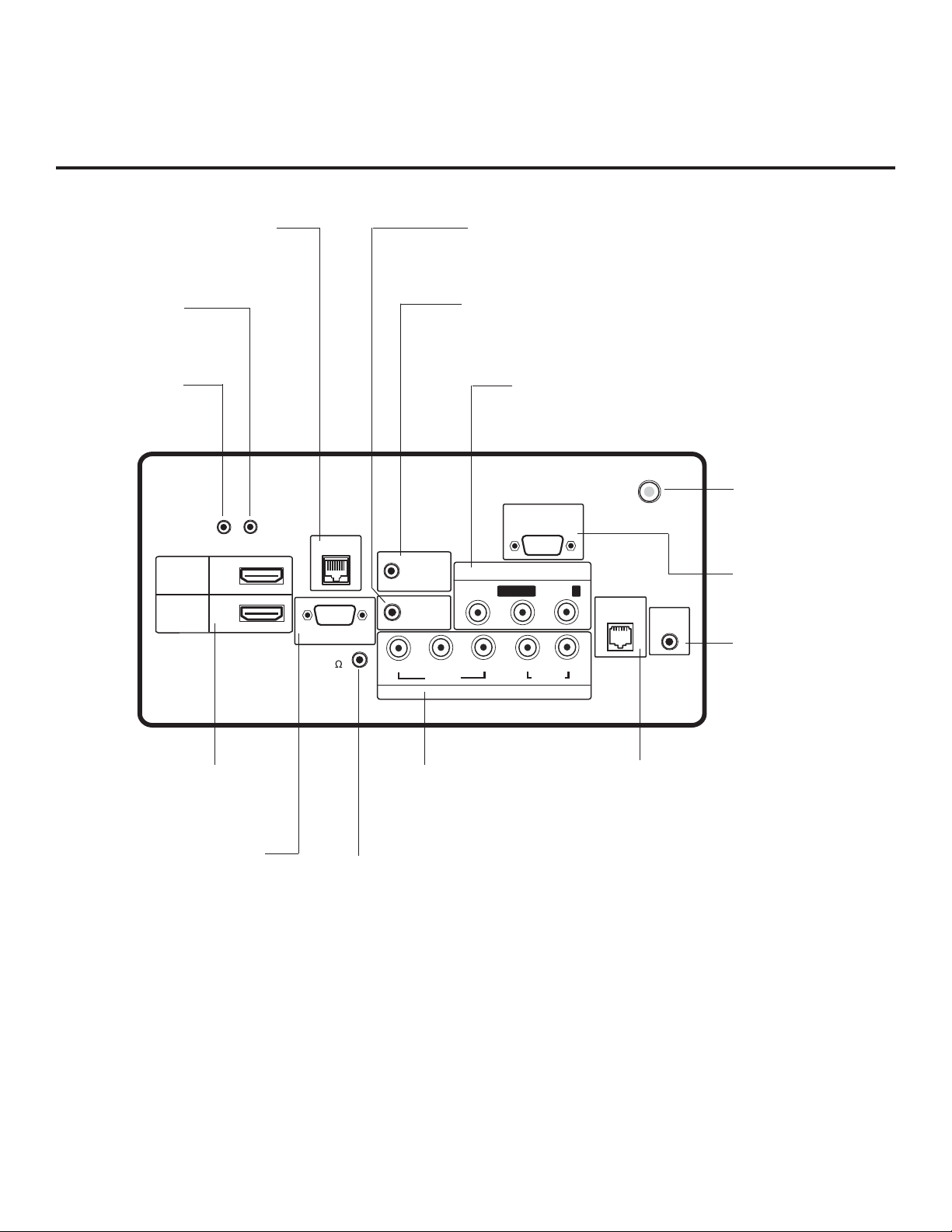
LD320H/LD325H Rear Jack Panel
Connection for Remote Jack
Pack (RJP) Control cable.
UPDATE
Restricted to
software updates.
RESET
Press RESET to
re-initialize the TV.
RJP
AUDIO IN (RGB/DVI)
Audio connection for
RGB or DVI device.
REMOTE CONTROL OUT
IR output for controlling an
auxiliary device.
AUDIO/VIDEO IN 1
Connection for composite audio/
video output from external device.
ANTENNA IN
26LD320H only.
Connect to Antenna/
CATV.
RS-232C IN
Use for downloading
software updates, etc.
TV-LINK CFG
Use for local FTG
configuration.
HDMI/DVI IN
Connection for HDMI/DVI
output from external device.
COMPONENT IN
Connection for component
output from external device.
GAME CONTROL
EBL in LodgeNet PPV Mode only.
RGB IN (PC)
Connection for RGB
output from PC.
SPEAKER OUT (8Ω) **
Connect to 8 ohm self-powered
speaker input. Intended for special
applications, such as a powered bathroom speaker with volume control.
* For 26LD320H TVs, this is a GAME CONTROL/MPI port. GAME CONTROL function as described
above. When the EBL is in Pass-through Mode, the MPI function enables an external MPI control device
(i.e., clone programmer, VOD/PPV STB, etc.) to control the TV.
** This stereo jack provides a mono speaker fixed-level, 1 watt output (audio +, audio -, w/ground shield).
Do NOT plug in a mono connector, as this may damage the TV.
8
*
206-4163
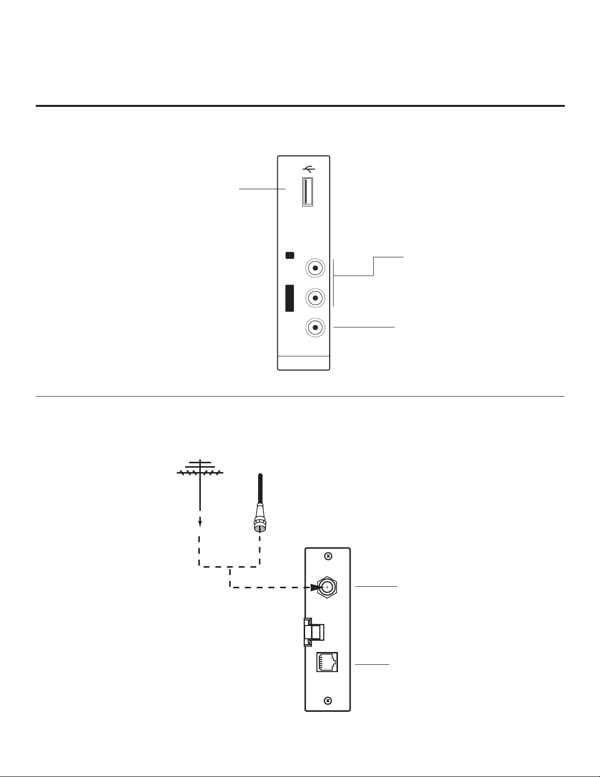
Side Connections Panel / RF Antenna & MPI Connections
Side Connections Panel
USB IN
Insert USB memory device for
software updates, cloning pur-
poses, or picture/music enter-
tainment, as applicable.
RF Antenna & MPI Connections
(32/37/42LD320H and 32/37LD325H TVs)
Note: 26LD320H Antenna
and MPI connections are
on the rear jack panel (see
previous page).
Antenna
or CATV
USB IN
L/MONO -AUDIO- R
VIDEO
AV IN 2
A/V 2 Input
L/MONO-AUDIO-R IN
Connect to audio output jacks
on external device. For only
mono audio output, connect to
Left audio input.
VIDEO IN
Connect to video output port on
external device (see Reference
section, “TV Camport Auto Sense
Operation,” for further information).
206-4163
ANTENNA IN
ANTENNA IN
Connect to
Antenna/CATV.
MP I
MPI
Enables an external MPI control
device (i.e., clone programmer, VOD/
PPV STB, etc.) to control the TV when
the EBL is in Pass-through Mode.
9
Installer Overview
This is the Commercial Mode Setup Guide only.
Installer Menu / Commercial Mode Setup
To set up a Master TV, you will need to know how to enter the TV
Installer Menu and make changes to the default values as required.
Similarly, to configure a single TV’s Installer Menu settings in FTG Mode,
you will need to know how to access and use the FTG Configuration
Application utilities. If necessary, familiarize yourself with the Installer
Menu and how to make and save changes. Refer to page 14 for information on accessing the Installer Menu in Pass-through Mode. Refer to
page 23 for information on accessing the FTG Installer Menu
Configuration Utility in the FTG Configuration Application. Pages 15 to 20
describe Installer Menu items in detail.
Installer Remote
The LG Installer Remote is supplied with and dedicated to operate the
TV. See next page for typical key functions in TV operating mode. Some
DVD and VCR controls may be available for selected LG DVD/VCR
products.
Cloning
Cloning refers to the process of capturing a Master TV Setup and transferring it to a Target TV. The Master TV’s clonable features need to be
configured as part of the Commercial Mode Setup. This is a critical step.
If the Master TV’s clonable features—channel icons or labels, digital font
options, etc.—are not set up correctly, the cloned TVs will all have problems. Pages 27 to 32 provide detailed information on cloning requirements and procedures.
XXLD320H PTC INSTALLER MENU
000 INSTALLER SEQ 000
UPN 000-000-000-000 FPGA E0F1
PTC V1.00.000 CPU V3.06.00
Typical Installer Menu
TIMER
ALARM
INPUT
TV
123
456
7809
FLASHBK
i
VOL
MENU
INFO
PORTAL
MUTE
GUIDE
CH
CC
P
A
G
E
10
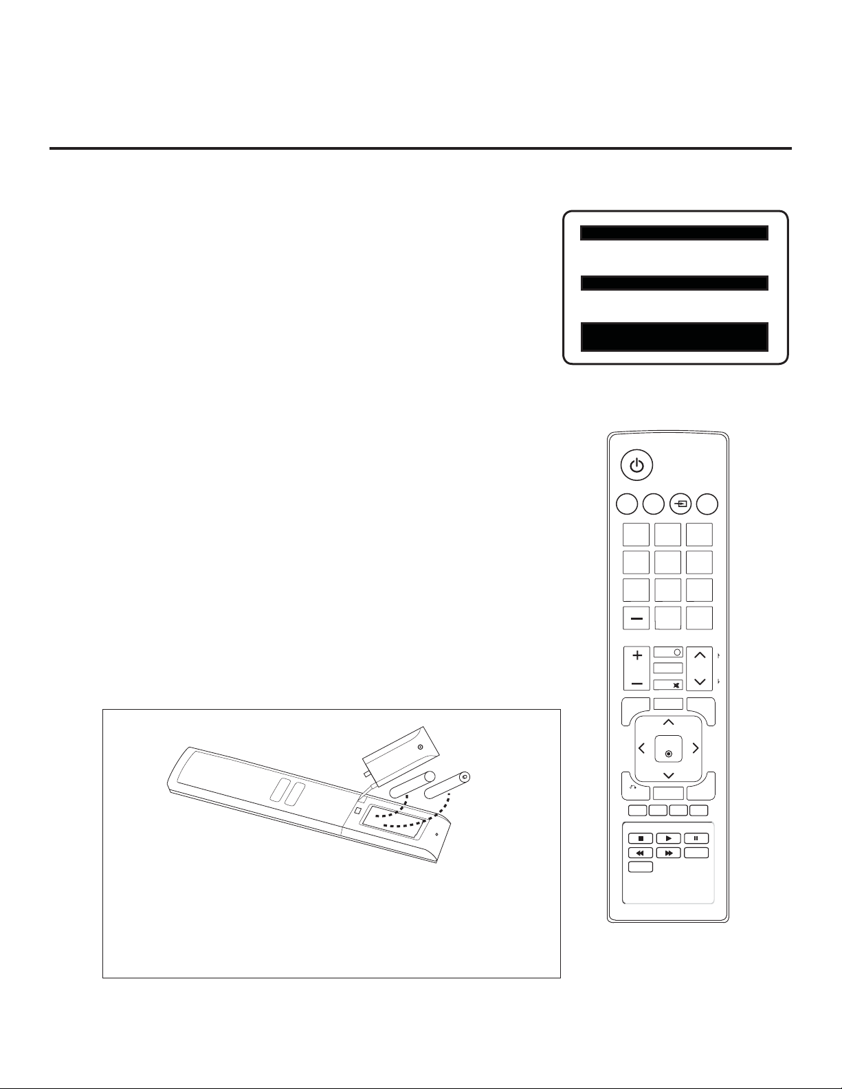
AAA +
+ AAA
Installing Batteries in Installer
Remote
• Open the battery compartment cover on the back side of the remote.
• Install two high-quality alkaline 1.5V AAA batteries. Never mix old
or used batteries with new ones. Install batteries matching correct
polarity as shown (+ with + and - with -).
• Replace the battery compartment cover.
BACK
RATIO
ENTER
SAP
EXIT
EJECT
206-4163
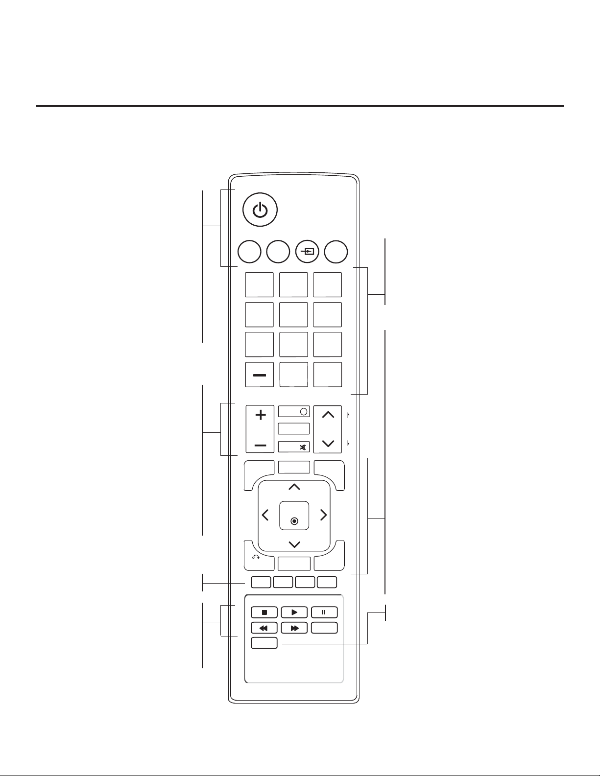
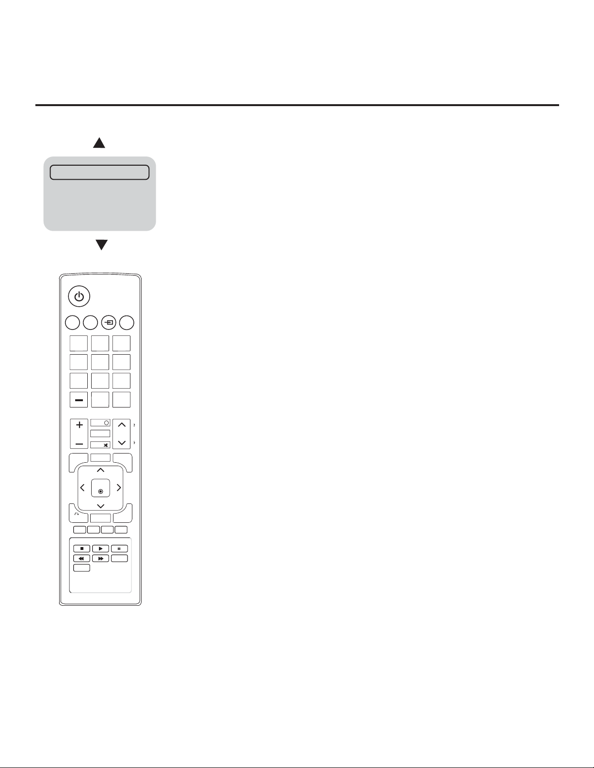
Installer Remote Control Typical Key Functions
The LG Installer Remote illustrated below and throughout this document shows typical remote control functions and
is provided for reference only. This Installer Remote may vary from the Installer Remote supplied with the TV.
POWER
Turns TV On or Off.
ALARM
Sets the time when the TV
will automatically turn itself ON.
TIMER
Sets the amount of time before the TV
automatically turns itself OFF.
INPUT
Selects RGB, HDMI/DVI1, HDMI2,
Component Input, AV1, and AV2 sources.
TV
Returns to the last TV channel.
VOLUME UP/DOWN
Increases/decreases sound level.
INFO
Displays channel information.
PORTAL
Displays and removes the interactive
menu.
MUTE
Switches sound ON or OFF.
CHANNEL UP/DOWN
Selects available channels found with
Auto Tuning. Moves to next available
page in electronic program guide.
Color buttons access special functions
in some menus.
VCR/DVD BUTTONS
Controls some video cassette
recorders or DVD players.
EJECT
Ejects a USB memory device, CD,
DVD, VHS tape, as applicable.
ALARM
TIMER
INPUT
TV
123
456
7809
FLASHBK
i
INFO
VOL
MENU
BACK
RATIO
PORTAL
MUTE
GUIDE
ENTER
SAP
CH
CC
EXIT
EJECT
NUMBER Buttons (0 - 9) DASH
Use to enter a program number or channel.
Dash is used for sub-channel numbers such
as 2-1, 2-2, 9-1, 9-2, 100-3, 100-4, etc.
FLASHBK (FLASHBACK)
Returns to the previously tuned channel.
Arrows (Up/Down/Left/Right) & ENTER
Use to navigate on-screen menus and
adjust TV settings to your requirements.
MENU
Provides access to the TV setup menus on
the screen. Also, enters or exits the onscreen menu system.
P
A
G
E
GUIDE
Displays and removes the electronic
program guide.
CC
Press to activate subtitles.
BACK
Returns one level to the previous menu/
display .
SAP
Analog Mode: Selects MTS sound (Mono,
Stereo, or SAP). DTV Mode: Changes
audio language, if additional languages are
available. *
EXIT
Clears all on-screen displays and returns to
TV viewing.
RATIO
Adjusts the picture aspect ratio.
SAP notes:
*
• If SAP is selected and no SAP is provided, sound
may not be heard on channel.
• Each analog channel may have its own SAP setting.
• Digital channels will reset to default audio language
with a power off/on.
206-4163
11
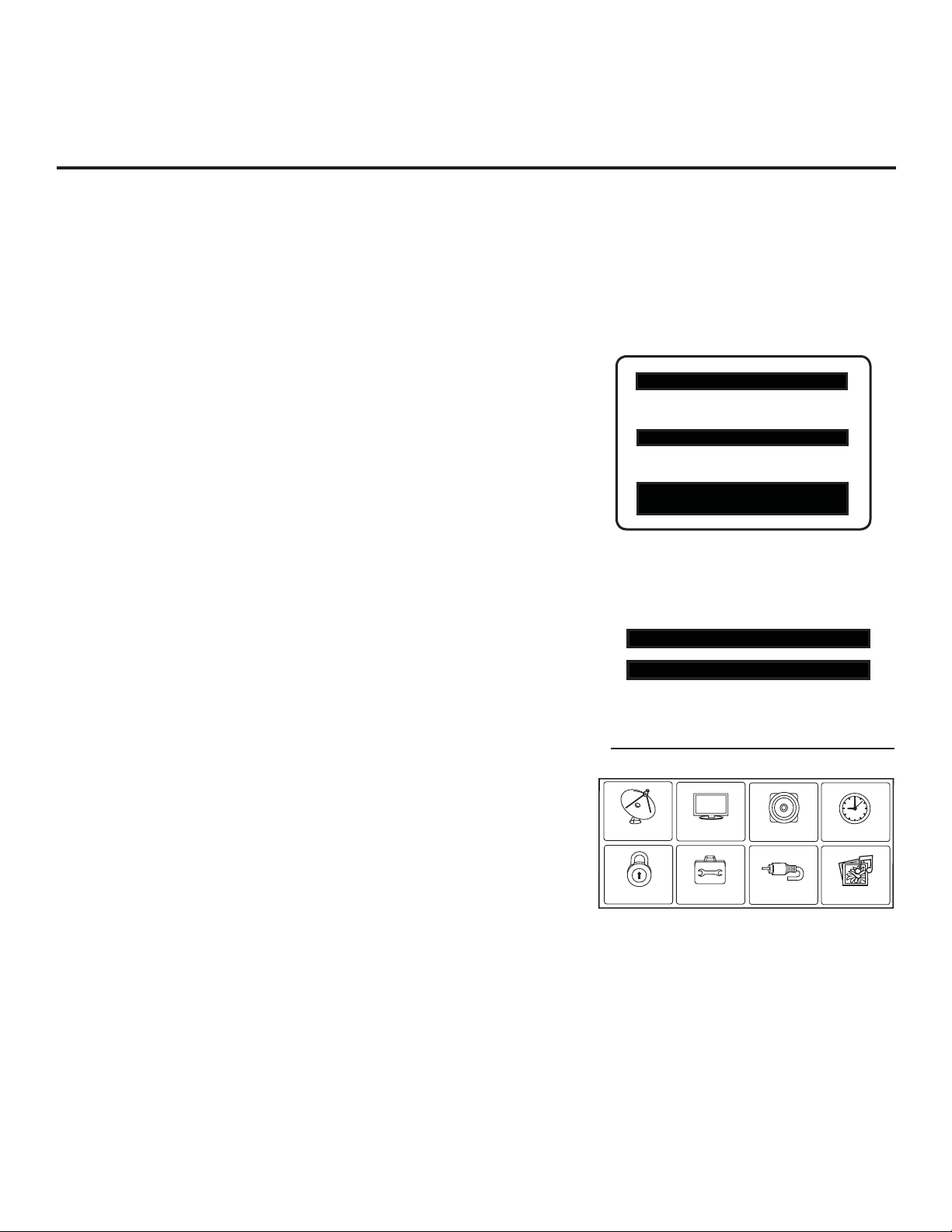
Commercial Mode Setup for Master TV
CHANNEL
PICTURE
AUDIO
INPUT
OPTION
LOCK
TIME
MY MEDIA
This section describes how to set up a Master TV when the EBL is in Pass-through Mode.
Note: Disconnect all Aux inputs. Under certain conditions, Auto Tuning (Channel Search) is disabled if
there is an Aux input active.
Note: Refer to “FTG Mode of Operation” on pages 23 to 26 for information on confi guring/editing
Channel Map and Installer Menu settings for an individual TV in FTG Mode.
1. Set Installer Menu items.
a) Use the Installer Remote to enter the TV Installer Menu: Press
MENU repeatedly until the on-screen menu locks up, and then
press 9-8-7-6 + ENTER. Refer to pages 14 to 20 for detailed
information on Installer Menu items.
b) Set Installer Menu item 117 FACT DEFAULT to 001 and press
ENTER on the Installer Remote.
This clears all Installer Menu custom settings, channel labels/
icons, etc. and reloads the factory default settings. The value
will change back to 0 after the internal TV controller (Protocol
Translator Card [PTC]) has been restored to factory default
condition. This step ensures that the TV Channel Memory will
be the active Channel List.
c) Set Installer Menu item 003 BAND/AFC, as appropriate.
• Broadcast: Set to 000.
• CATV: Set to 001 (default).
• HRC: Set to 002.
• IRC: Set to 003.
d) Set any other Installer Menu items that affect your TV program-
ming network to the required confi guration. For example, en-
able/disable Aux sources, set a Start Channel, etc.
e) After you have adjusted all required Installer Menu item set-
tings, press ENTER on the Installer Remote to exit the menu
and save your changes.
XXLD320H PTC INSTALLER MENU
000 INSTALLER SEQ 000
UPN 000-000-000-000 FPGA E0F1
PTC V1.00.000 CPU V3.06.00
Typical TV Installer Menu
Note: The Installer Menu header will vary
depending on the TV you are setting up.
117 FACT DEFAULT 001
003 BAND/AFC 00X
Adjust the settings for these
Installer Menu items.
2. Set up TV features.
On-screen setup menus control the features of the TV (see page
21). Press MENU on the Installer Remote to access the setup
menus, and then set Channel, Picture, Audio, Lock, Time, etc.
options to the desired configurations. See also the Clonable Menu
Features list on page 27.
Note: If desired, you can run Auto Tuning (see step 3) prior to
completing this step.
12
Set the TV features to the desired
configuration for the end user.
(Continued on next page)
206-4163
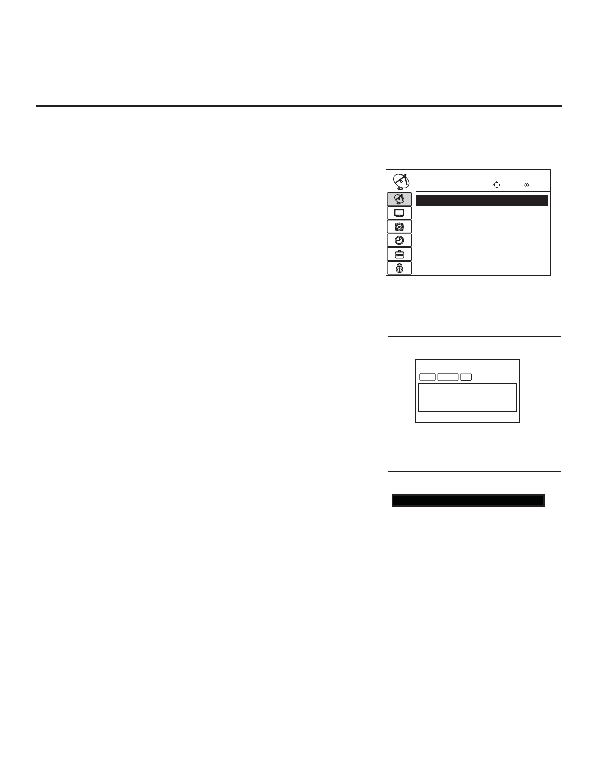
Commercial Mode Setup for Master TV (Cont.)
CHANNEL
Enter
Move
$XWR7XQLQJ
0DQXDO7XQLQJ
&KDQQHO(GLW
&KDQQHO/DEHO
(Continued from previous page)
3. Run Auto Tuning (Channel Search).
a) Search for all available analog and digital channels: Go to the
Channel Menu, select the Auto Tuning option, and follow the
on-screen instructions.
b) Use the Channel Edit option in the Channel Menu to edit the
channel lineup, as necessary, to include free to guest channels
only.
• Add/delete channels per your system requirements. Note that
physical channel numbers are used to identify virtual channels.
Also, channel numbers cannot be higher than 255.
• Use the Channel Label option in the Channel Menu to add
familiar channel trademarks/logos such as ABC, CBS, NBC,
etc. to the Channel-Time on-screen display. Identifi able labels
(logos) should enable the end user to readily know what common networks are available. (You can add the channel labels
in this step, or you can add channel logos or labels for channels
without icons in step 5.)
4. Transfer the TV Setup to the internal TV Controller (PTC):
2-5-5 + MENU Mode
After the TV channel lineup has been edited and channel label icons
added, enter the Installer Menu. Once in the Installer Menu, press
2-5-5 + MENU on the Installer Remote to initiate the transfer of the
Master TV Setup to the PTC. Once the transfer is complete, the TV
will exit the Installer Menu.
Note: The maximum number of active channels that can be trans-
ferred is 141. Total channels numbering more than 141 will result in
erratic TV operation.
5. Add Custom Channel and Aux Source Labels for Analog
Channels: 2-5-4 + MENU Mode
Enter the Installer Menu, and press 2-5-4 + MENU on the Installer
Remote. Add/edit custom text labels to channel on-screen displays.
Note that digital channels often have a broadcaster generated label
(see 2-5-4 + MENU procedural information on page 22). When you
are finished, press MENU to exit 2-5-4 + MENU Mode.
6. Verify the TV setup.
At this point, verify that the channel lineup, channel icons, and cus-
tom labels are correct. Make sure the TV features are set per your
requirements.
Run Auto Tuning, edit channels, and select
familiar channel trademarks/logos using
Channel Menu options.
DIGITAL 19-3
STEREO SAP
MONO
WXYZ
Custom Text Label “WXYZ” created in
2-5-4 + MENU (Add Channel Label) Mode.
028 CH. OVERIDE 000
After verifying the TV Setup, set Installer
Menu item 028 CH. OVERIDE to 000.*
*
This step prevents end users from
accessing channel settings (i.e., the
Channel Menu will be inaccessible/
grayed out).
7. Lock the channel lineup.
Enter the Installer Menu, and set item 028 CH. OVERIDE to 000 to
lock the channel lineup and restrict access to the TV setup menus.*
Press ENTER to exit the Installer Menu and save your changes.
The Master TV Setup is now ready to be copied to a clone programmer
(see cloning information in this document).
206-4163
13

Installer Menu
Use the Installer Menu to set up or change operational settings.
Refer to the table starting on the next page for brief descriptions of Installer Menu
items. More detailed descriptions follow the table listing.
Accessing the Installer Menu
Make sure the TV is ON. Using an Installer Remote, press MENU repeatedly
until the on-screen setup menus lock up, and then press 9-8-7-6 + ENTER to
access the Installer Menu.
The Installer Menu opens with item 000 INSTALLER SEQ 000. Use the Up/
Down arrow keys to sequence through the available menu items, or access
an item directly by keying in the line number and then pressing MENU. For
example, to access the SLEEP TIMER option, which is item 015, press 0-1-5
+ MENU. To change a setting, use the Left/Right arrow keys, or enter a value
directly.
XXLD320H PTC INSTALLER MENU
000 INSTALLER SEQ 000
UPN 000-000-000-000 FPGA E0F1
PTC V1.00.000 CPU V3.06.00
Using the Installer Menu
Items 000 ~ 119 are immediately accessible only upon entering the Installer
Menu. Refer to the table on pages 15 and 16 for an overview of Installer
Menu items, including item numbers, functions, ranges, and default values.
Installer Menu items not relevant to these TV series are not present on the
Installer Menu; therefore, some numbers are missing. For example, item 006
will not appear.
Exiting the Installer Menu and Activating Updates
To exit the Installer Menu, press ENTER again. Any changes you make will
be stored in non-volatile memory.
Typical TV Installer Menu
14
206-4163

Installer Menu Items 000 through 071
Installer Menu (Cont.)
Menu
Item
Function Value Range Default Value Brief Description of Function and Comments
000 INSTALLER SEQ 0 ~ 3 0 Leave default set to 0.
001 POWER MANAGE 0 ~ 7 0 Sets number of hours of no activity before automatic shutoff.
002 AC ON 0 / 1 0 Set to 1 to enable Auto Turn ON when AC power is applied.
003 BAND/AFC 0 ~ 3 1 Selects Tuning Band: 0=Broadcast, 1=CATV, 2=HRC, 3=IRC
004 STRT CHANNEL 0 ~ 127, 255 255
005 CHAN LOCK 0 / 1 0 If set to 1, cannot tune from current channel.
007 STRT VOLUME 0 ~ 63, 255 255
008 MIN VOLUME 0 ~ 63 0 Sets minimum allowable volume setting.
009 MAX VOLUME 0 ~ 63 63 Sets maximum allowable volume setting.
010 MUTE DISABLE 0 / 1 0 Set to 1 to disable Mute Function.
011 KEY DEFEAT 0 / 1 0 Set to 1 to disable menu navigation keys on display panel.
015 SLEEP TIMER 0 / 1 1 Set to 1 to enable Sleep Timer.
016 EN TIMER 0 / 1 0 Set to 1 to enable On/Off Timers.
017 ALARM 0 / 1 1 Set to 1 to enable Alarm.
020 FEATURE LEVEL 0 ~ 1, 16 ~ 24 1 Determines the IR code scheme to which the TV will respond.
021 V-CHIP 0 / 1 1 Set to 1 to enable V-Chip (Parental Control) functions.
022 MAX BLK HRS 0 ~ 99 12 Sets number of V-Chip blocking hours.
023 CAPTION LOCK 0 / 1 0 Set to 1 to retain caption setting set before TV turned OFF.
028 CH. OVERIDE 0 / 1 1 If set to 0, limits direct access to favorite channels.
029 OLD OCV 0 / 1 0 Set to 1 to change MPI operation to OCV.
030 ACK MASK 0 / 1 0 If set to 1, changes MPI for some OCV boxes.
031 POLL RATE 20 ~ 169 94 Selects poll rate for MPI.
032 TIMING PULSE 186 ~ 227 207 Sets baud rate for MPI.
034 CAMPORT EN 0 / 1 1 Set to 1 to enable Video 2 input.
035 COMPPORT EN. 0 / 1 1 Set to 0 to disable HDMI 1. Set to 1 enable HDMI 1.
038 YPrPb EN. 0 / 1 1 Set to 1 to enable display panel Component Video 1 input jacks.
039 REAR AUX EN 0 / 1 1 Set to 1 to enable display panel Video 1 input jack.
040 AUTO CAMPORT 0 / 1 1
046 STRT AUX SRCE 1 ~ 6, 255 6 Sets the starting Aux source (if item 004 STRT CHANNEL is set to 0).
047 AUX STATUS 0 / 1 0
053 DIS. CH-TIME 0 / 1 0 Set to 1 to disable Channel-Time display.
069 EN. CH-T COL. 0 / 1 1 Set to 1 to enable custom color for the Channel-Time display.
070 FOR. CH-TIME 0 ~ 7 2 Chooses custom foreground color for the Channel-Time display.
071 BCK. CH-TIME 0 ~ 7 2 Chooses custom background color for the Channel-Time display.
Channel tuned when TV is turned ON. (Set to 255 to tune to channel
tuned before TV turned OFF.)
Volume level when TV is turned ON. (Set to 255 to use volume level
before TV turned OFF.)
Set to 1 to automatically switch to Camport. If set to 1, STRT AUX SRCE
cannot be set to 2.
Set to 1 for MPI Aux source to be reported as a channel number instead of
Channel 0.
206-4163
15
 Loading...