

Page 1

OWNER’S MANUAL
LCD TV
Please read this manual carefully before operating
your set and retain it for future reference.
www.lg.com
Page 2

HDMI, the HDMI logo and High-Definition Multimedia Interface are trademarks or registered trademarks of HDMI Licensing LLC.
Page 3
1
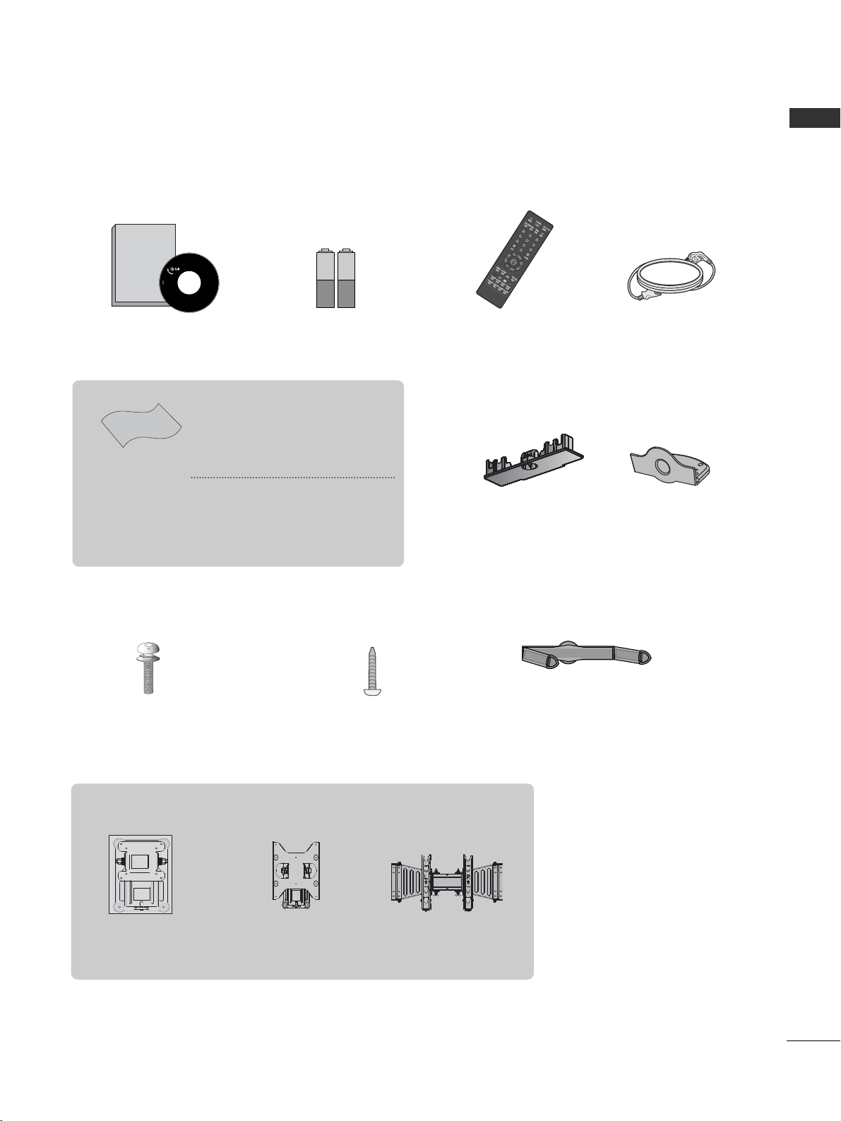
Ensure that the following accessories are included with your TV. If an accessory is missing, please contact the
dealer where you purchased the product.
■
Image shown may differ from your TV.
Owner's
Manual
Owner’s manual
Owner’s Manual Batteries
Power Cord
Polishing Cloth
Polishing cloth for use
on the screen
This feature is not
available
for all models.
*Lightly wipe any stains or
fingerprints on the surface
of the TV with the polishing
cloth.
Do not use excessive force.
This may cause scratching or
discolouration.
Bolts for stand assembly
(Refer to p.6)
(Only 26/32LD310)
x 4
1-Screw for stand fixing
(Refer to p. 8)
(Only 26/32LD310)
ACCESSORIES
RATIO
Remote Control
Cable Management Clip
(Refer to p. 7)
(Only 19/22LD310)
Protection Cover
(Refer to p. 9)
Wall Mounting Bracket(Separate purchase)
AW-47LG30M
(32LD310)
(19/22LD310)
RW120
(26/32LD310)
RW230
ACCESSORIES
or
Page 4

Picture Size (Aspect Ratio)Control .........................33
Preset Picture Settings
- Picture Mode-Preset............................................34
Manual Picture Adjustment
- Picture Mode-User option ............................. 35
Picture Improvement Technology...........................36
Picture Reset..................................................................38
Power Indicator..............................................................38
Screen Setup ................................................................39
- Manual Configure (Adjustment for screen Position) .39
- Initializing (Reset to original factory settings)..............40
Remote Control Key Functions..................................20
Turning on the TV....................................................... 22
Installation Guide........................................................ 22
Programme Selection ................................................. 22
Volume Adjustment......................................................22
On Screen Menus Selection and Adjustment ......23
PICTURE CONTROL
WATCHING TV / PROGRAMME CONTROL
AACCCCEESSSSOORRIIEESS
.....................................................1
2
CONTENTS
CONTENTS
Front Panel Controls................................................... 4
Back Panel Information.............................................. 5
Stand Installation..........................................................6
Back Cover for Wire Arrangement........................... 7
Attaching the TV to a desk ........................................8
Positioning your display..............................................8
Swivel Stand ................................................................. 8
Not using the desk-type stand..................................9
Kensington Security System ...................................10
Careful Installation Advice
............................................10
Desktop Pedestal Installation ................................. 11
Wall Mount: Horizontal installation....................... 11
Antenna Connection ................................................ 12
PREPARATION
EXTERNAL EQUIPMENT SETUP
HD Receiver Setup .......................................................13
DVD Setup..................................................................... 15
VCR Setup ..................................................................... 17
Other A/V Source Setup........................................... 18
External Stereo Setup..................................................18
Auto Programme Tuning............................................ 24
Manual Programme Tuning ....................................... 25
Fine Tuning.....................................................................26
Assigning a Station Name..........................................27
Programme Edit ........................................................... 28
Favourite Programme .................................................. 29
Selecting the Programme List.................................. 30
Key lock.......................................................................... 31
Factory Reset .................................................................32
Page 5

SOUND & LANGUAGE CONTROL
Preset Sound Settings - Sound Mode ....................41
Sound Setting Adjustment - User Mode ...............42
Auto Volume Leveler ....................................................43
Balance............................................................................44
Audio Reset....................................................................45
I/II
- Stereo/Dual Reception....................................... 46
- NICAM Reception ....................................................... 47
- Speaker Sound Output Selection.................... 47
On-Screen Menu Language Selection
...................... 48
3
CONTENTS
APPENDIX
Troubleshooting............................................................55
Maintenance .................................................................57
Product Specifications ................................................58
IR Codes ....................................................................... 59
TIME SETTING
Clock Setup......................................................................49
Auto On/Off Timer Setting .........................................50
Sleep Timer Setting........................................................51
TELETEXT
Switch On/Off .............................................................52
SIMPLE Text....................................................................52
TOP Text .........................................................................53
FASTEXT .........................................................................53
Special Teletext Functions..........................................54
Page 6
4
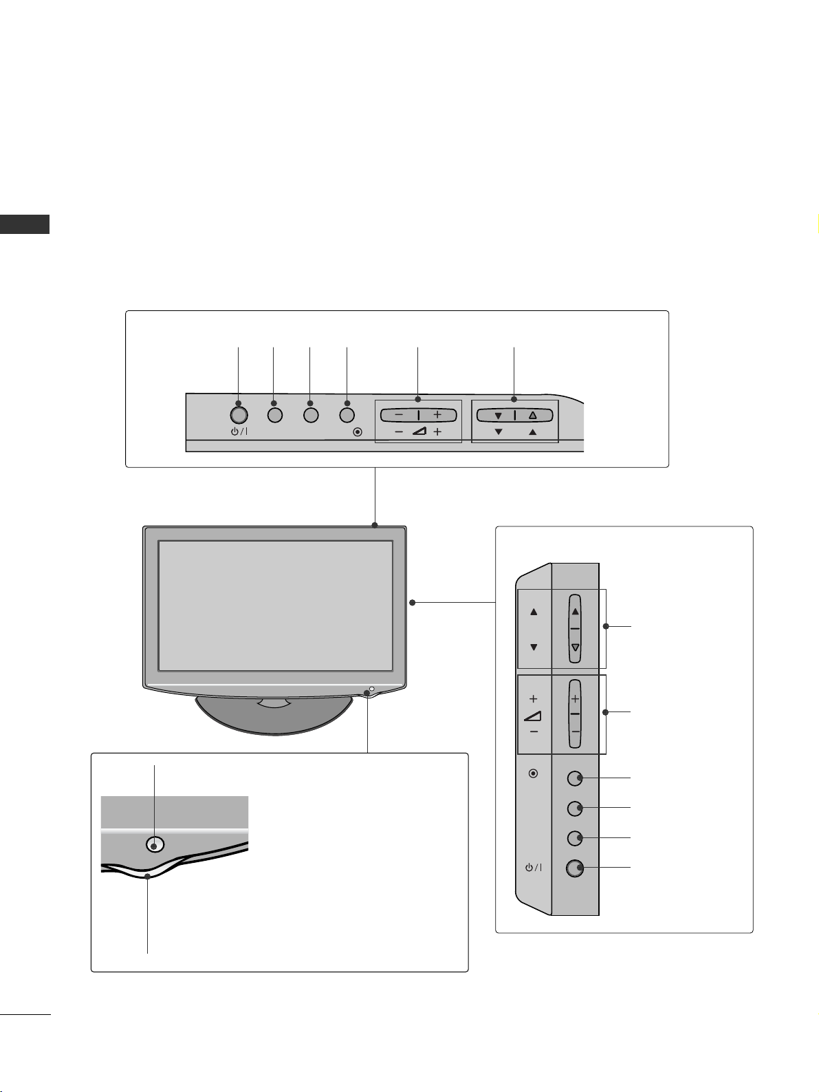
FRONT PANEL CONTROLS
PREPARATION
PREPARATION
■
This is a simplified representation of the front panel. Image shown may differ from your TV.
(Only 32LD310)
INPUT MENUPOK
PROGRAMME
VOLUME
(Only 19/22/26LD310)
INPUT
MENU
OK
P
PROGRAMME
VOLUME
OK
MENU
INPUT
POWER
OK
INPUT
POWER
MENU
Remote Control Sensor
Power/Standby Indicator
Illuminates red in standby mode.
Illuminates blue when the TV is switched on.
19/22/26/32LD310
Page 7
5
PREPARATION
IN
SERVICE ONLY
AUDIOVIDEO
ANTENNA
IN
COMPONENT IN
AUDIO OUT
VIDEO
AUDIOAUDIO
L( MONO)
R
AV IN
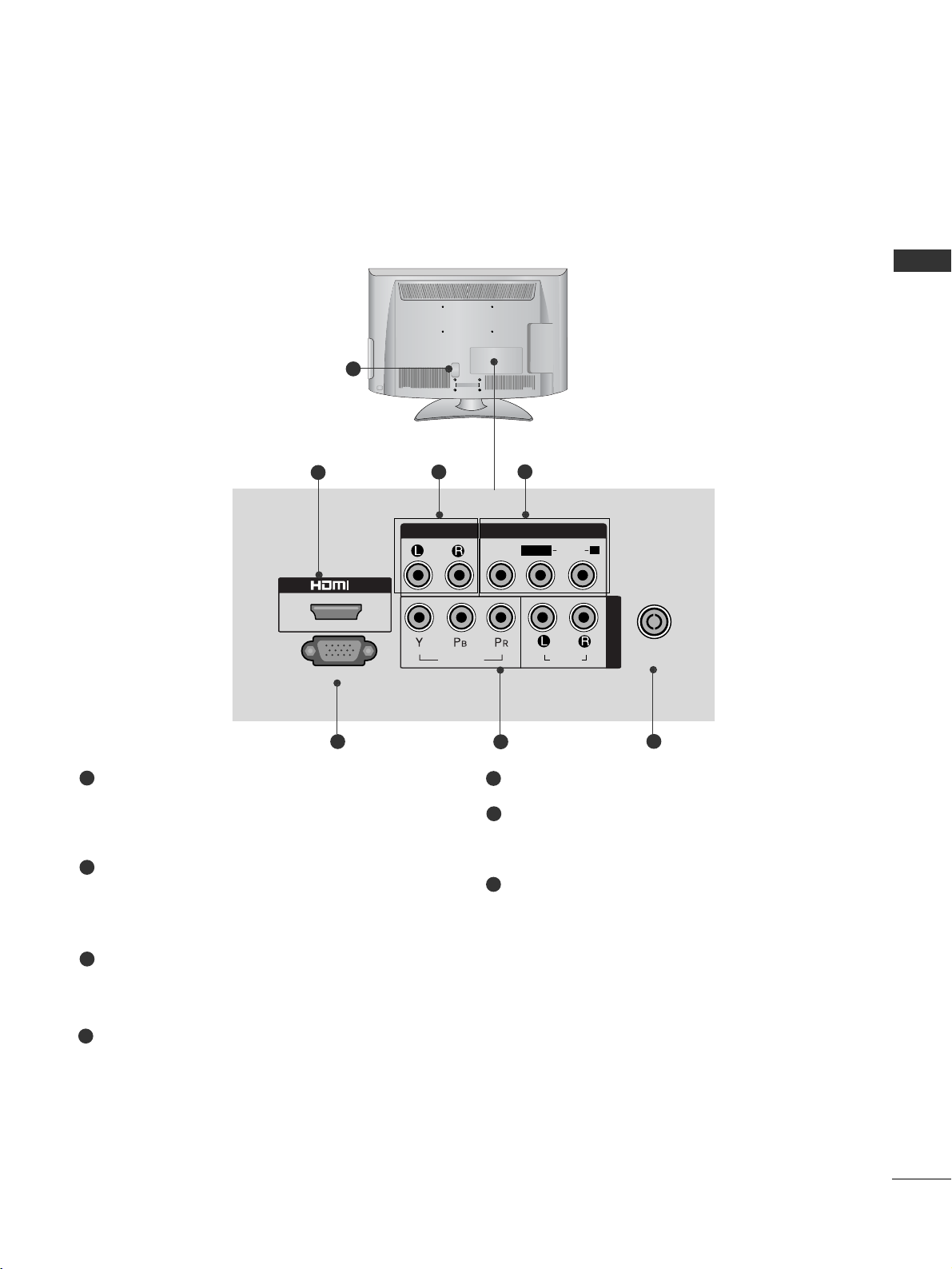
Power Cord Socket
This TV operates on an AC power. The voltage is
indicated on the Specifications page. Never
attempt to operate the TV on DC power.
HDMI Input
Connect a HDMI signal to HDMI IN.
This TV does not support DVI(VIDEO) signal
using DVI to HDMI cable.
Audio Output
Connect an external amplifier, or add a subwoofer
to your surround sound system.
Audio/Video Input (AV IN)
Connect audio/video output from an external
device to these jacks.
SERVICE ONLY PORT
Component Input
Connect a component video/audio device to
these jacks.
Antenna Input
Connect RF antenna to this jack.
1
2
3
4
5
7
BACK PANEL INFORMATION
A
Image shown may differ from your TV.
1
2
3
5
6
7
4
6
Page 8
6
PREPARATION
PREPARATION
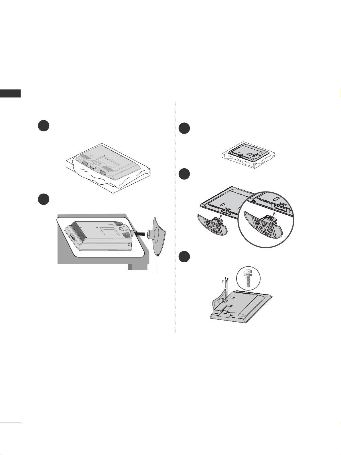
STAND INSTALLATION
■
Image shown may differ from your TV
When assembling the desk type stand, check whether the bolt is fully tightened. (If not tightened fully, the product can
tilt forward after the product installation.) If you tighten the bolt with excessive force, the bolt can deviate from abrasion
of the tightening part of the bolt.
1
Carefully place the TV screen side down on a cushioned surface to protect the screen from damage.
2
Assemble the TV as shown.
Only 19/22LD310
Cover Base
1
2
3
Carefully place the TV screen side down on a cushioned
surface to protect the screen from damage.
Assemble the TV as shown.
Fix the 4 bolts securely using the holes in the
back of the TV.
Only 26/32LD310
Page 9
7
PREPARATION
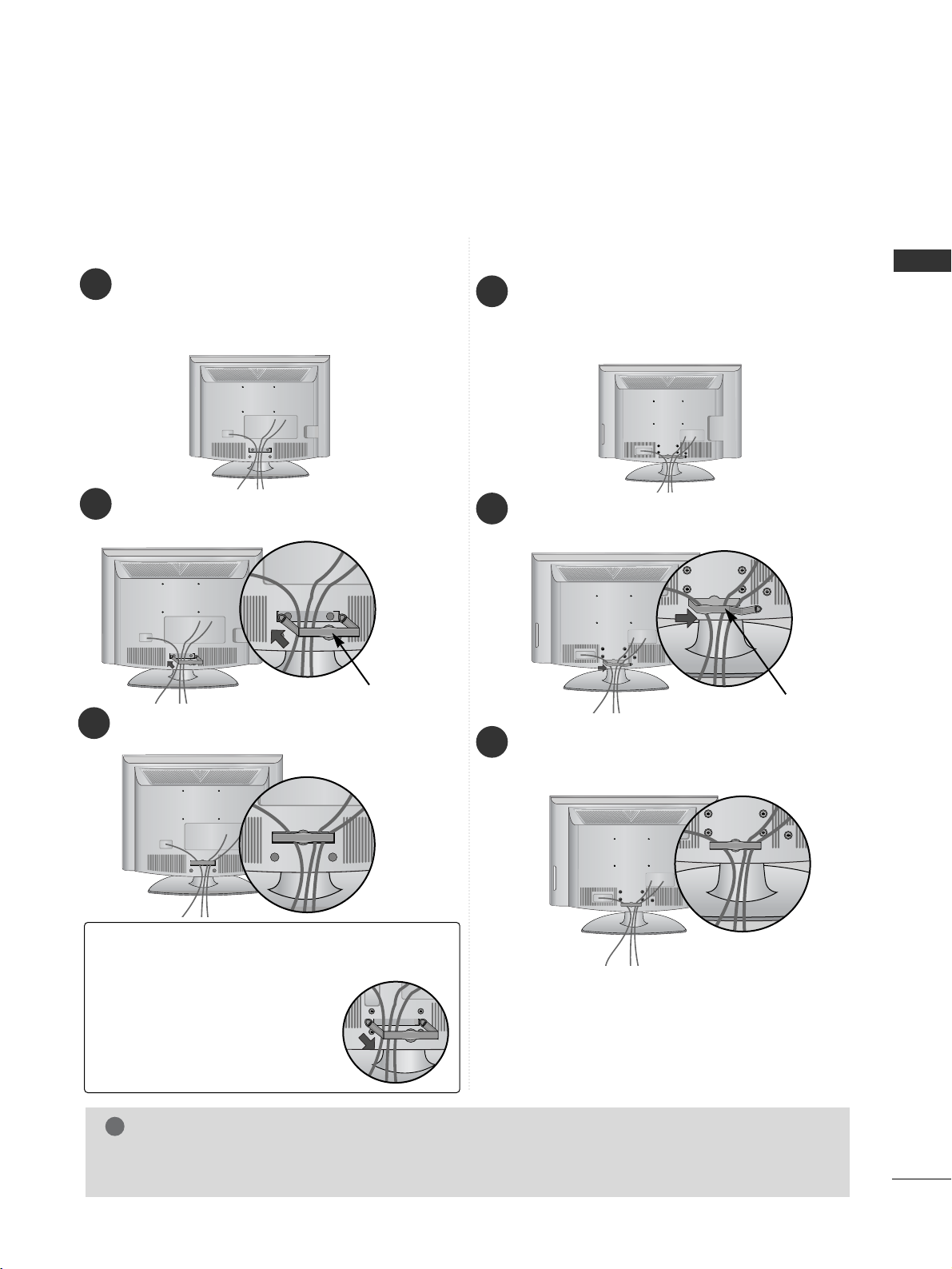
BACK COVER FOR WIRE ARRANGEMENT
■
Image shown may differ from your TV.
Only 26/32LD310
Only 19/22LD310
Hold the CABLE MANAGEMENT
CLIP with both hands and pull it
backward.
NOTE
!
GG
Do not use the CABLE MANAGEMENT CLIP to lift the TV.
- If the TV is dropped, you may be injured or the TV may be damaged.
How to remove the cable management
clip
(Only 19/22LD310)
Connect the cables as necessary.
To connect additional equipment, see the
External Equipment Setup section of the
manual.
1
Install the
CCAABBLLEE MMAA NNAAGG EE MMEE NNTT CCLL IIPP
as
shown.
2
CABLE MANAGEMENT CLIP
Fit the CABLE MANAGEMENT CLIP as shown.
3
Connect the cables as necessary.
To connect additional equipment, see the
External Equipment Setup section of the
manual.
1
Open the
CCAABBLLEE MMAANNAAGGEEMMEENNTT CCLL II PP
as
shown and manage the cables.
2
CABLE MANAGEMENT CLIP
Fit the
CCAABBLLEE MMAANNAAGGEEMMEENNTT CCLL II PP
as
shown.
3
Page 10
8
PREPARATION
PREPARATION
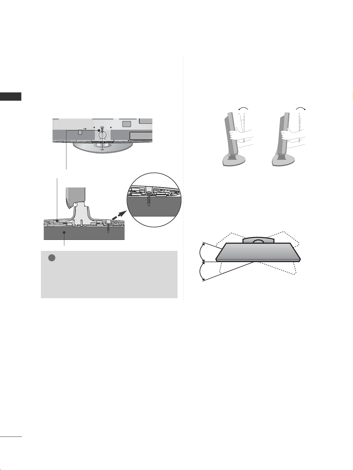
ATTACHING THE TV TO A DESK
(Only 26/32LD310)
■
Image shown may differ from your TV.
The TV must be attached to desk so it cannot be
pulled in a forward/backward direction, potentially
causing injury or damaging the product. Use only an
attached screw.
1-Screw
(provided as parts of the product)
Desk
Stand
WARNING
!
G
To prevent TV from falling over, the TV should
be securely attached to the floor/wall per
installation instructions. Tipping, shaking, or
rocking the machine may cause injury.
POSITIONING YOUR DISPLAY
(Only 19/22LD310)
■
Image shown may differ from your TV.
■
Adjust the position of the panel in various ways for
maximum comfort.
• Tilt range
12
0
3
0
SWIVEL STAND
(Only 26/32LD310)
■
Image shown may differ from your TV.
After installing the TV, you can adjust the TV set
manually to the left or right direction by 20 degrees
to suit your viewing position.
Page 11
9
PREPARATION
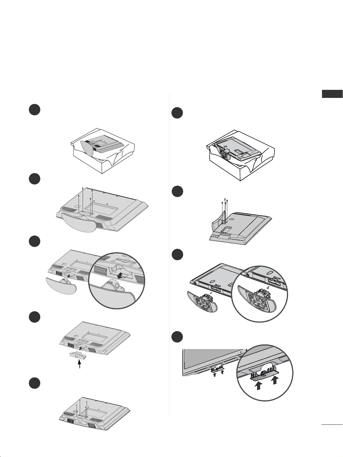
■
Image shown may differ from your TV.
When installing the wall-mounted unit, use the protection cover.
NOT USING THE DESK-TYPE STAND
Fix the 4 bolts securely using the holes in the
back of the TV.
5
Only 19/22LD310
1
3
4
Carefully place the TV screen side down on a
cushioned surface to protect the screen from
damage.
2
Loose the bolts from TV.
Detach the stand from TV.
Insert the
PPrroo tteecctt ii oo nn CCoo vveerr
into the TV.
PROTECTION COVER
Only 26/32LD310
1
Carefully place the TV screen side down on a
cushioned surface to protect the screen from
damage.
2
Loose the bolts from TV.
3
Detach the stand from TV.
PROTECTION COVER
4
Insert the
PPRROOTTEECCTTIIOONN CCOOVVEERR
into the TV
until clicking sound.
Page 12
10
PREPARATION
PREPARATION
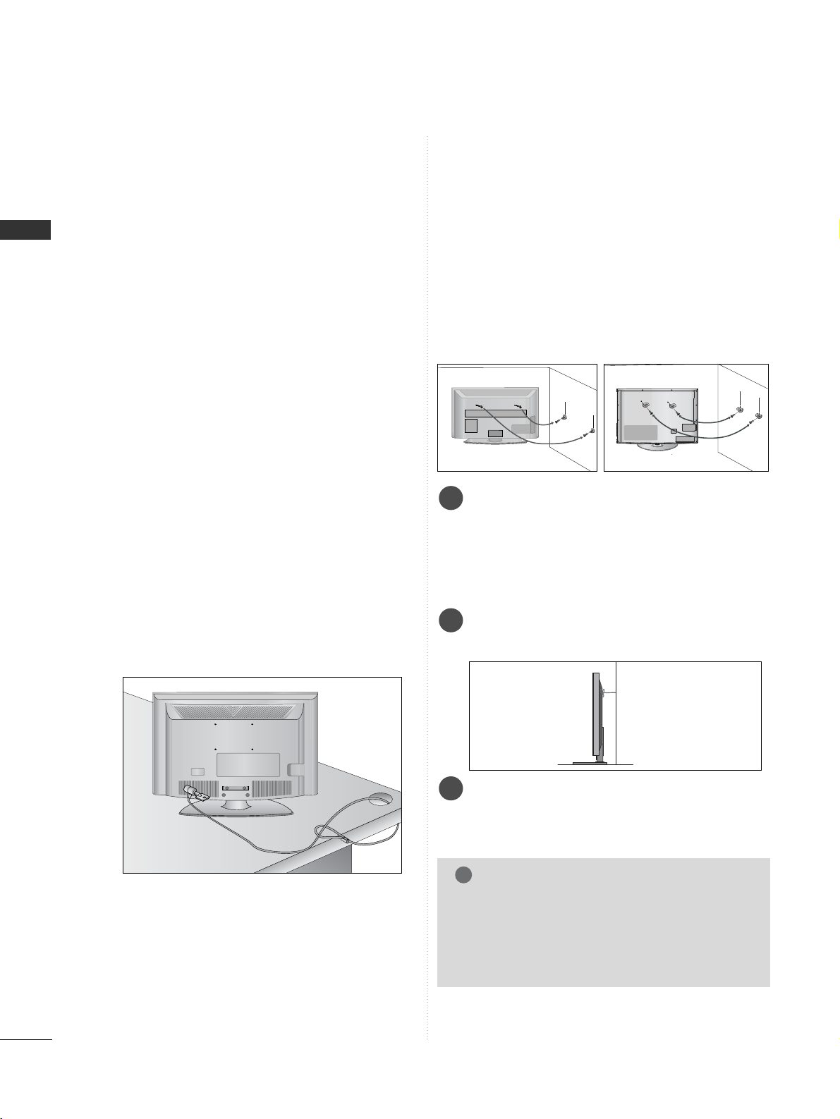
CAREFUL INSTALLATION ADVICE
A
You should purchase necessary components to fix the TV
safety and secure to the wall on the market.
A
Position the TV close to the wall to avoid the possibility
of it falling when pushed.
A
The instructions shown below are a safer way to set up
the TV, by fixing it to the wall, avoiding the possibility of
it falling forwards if pulled. This will prevent the TV from
falling forward and causing injury. This will also prevent
the TV from damage. Ensure that children do not climb
or hang from the TV.
NOTE
!
G
When moving the TV undo the cords first.
G
Use a platform or cabinet strong and large enough
to support the size and weight of the TV.
G
To use the TV safely make sure that the height of the
bracket on the wall and on the TV is the same.
3
1
2
Use the eye-bolts or TV brackets/bolts to fix the
product to the wall as shown in the picture.
(If your TV has bolts in the eyebolts, loosen then
bolts.)
* Insert the eye-bolts or TV brackets/bolts and tight-
en them securely in the upper holes.
Secure the wall brackets with the bolts on the wall.
Match the height of the bracket that is mounted on
the wall.
3
Use a sturdy rope to tie the product for alignment. It
is safer to tie the rope so it becomes horizontal
between the wall and the product.
2
1
2
1
KENSINGTON SECURITY SYSTEM
■
This feature is not available for all models.
■
Image shown may differ from your TV.
The TV is equipped with a Kensington Security
System connector on the back panel. Connect the
Kensington Security System cable as shown below.
For the detailed installation and use of the Kensington
Security System, refer to the user’s guide provided
with the Kensington Security System.
For further information, contact http://www.kensing-
ton.com, the internet homepage of the Kensington
company. Kensington sells security systems for expensive electronic equipment such as notebook PCs and
LCD projectors.
NOTE
- The Kensington Security System is an optional
accessory.
NOTES
a. If the TV feels cold to the touch, there may be a
small “flicker” when it is turned on.
This is normal, there is nothing wrong with TV.
b. Some minute dot defects may be visible on the
screen, appearing as tiny red, green, or blue spots.
However, they have no adverse effect on the monitor's performance.
c. Avoid touching the LCD screen or holding your fin-
ger(s) against it for long periods of time. Doing so
may produce some temporary distortion effects on
the screen.
Page 13
11
PREPARATION
4 inches
4 inches
4 inches
4 inches
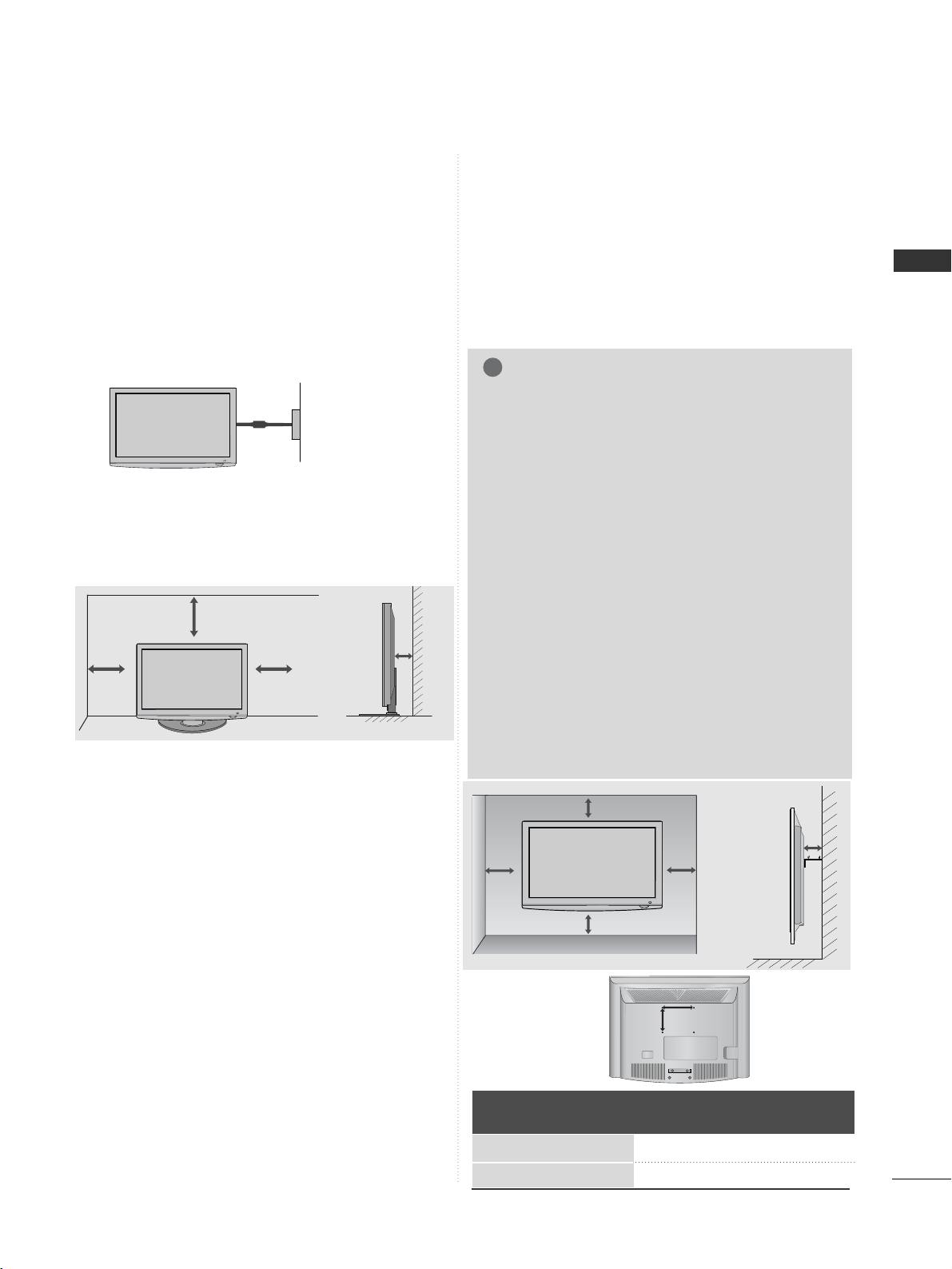
DESKTOP PEDESTAL INSTALLATION
For adequate ventilation allow a clearance of 4”
(10cm) all around the TV.
A
The TV can be installed in various ways such as on
a wall, or on a desktop etc.
A
The TV is designed to be mounted horizontally.
Power Supply
Circuit breaker
EARTHING
Ensure that you connect the earth wire to prevent
possible electric shock. If grounding methods are not
possible, have a qualified electrician install a separate
circuit breaker.
Do not try to earth the TV by connecting it to telephone wires, lightening rods or gas pipes.
WALL MOUNT: HORIZONTAL INSTALLATION
A
We recommend the use of a LG Brand wall mounting
bracket when mounting the TV to a wall.
A
We recommend that you purchase a wall mounting
bracket which supports VESA standard.
A
LG recommends that wall mounting be performed
by a qualified professional installer.
NOTE
!
G Should Install wall mount on a solid wall perpen-
dicular to the floor.
G Should use a special wall mount, if you want to
install it to ceiling or slanted wall.
G The surface that wall mount is to be mounted on
should be of sufficient strength to support the
weight of TV set; e.g. concrete, natural rock,
brick and hollow block.
G Installing screw type and length depends on the
wall mount used. Further information, refer to
the instructions included with the mount.
G LG is not liable for any accidents or damage to
property or TV due to incorrect installation:
- Where a non-compliant VESA wall mount is
used.
- Incorrect fastening of screws to surface which
may cause TV to fall and cause personal injury.
- Not following the recommended Installation
method.
4 inches
4 inches
4 inches
4 inches
4 inches
Model
VESA
(A *B)
Standard
Screw
Quantity
19/22LD310
26/32LD310
100 * 10 0
200 * 10 0M4M4
4
4
AA
BB
Page 14
12
PREPARATION
PREPARATION
RGB IN
ANTENNA
IN
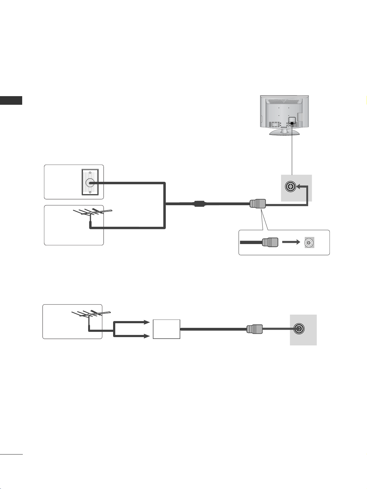
ANTENNA CONNECTION
■
For optimum picture quality, adjust antenna direction.
■
An antenna cable and converter are not supplied.
■
To prevent damage do not connect to the mains outlet until all connections are made between the devices.
RGB IN
ANTENNA
IN
Multi-family Dwellings/Apartments
(Connect to wall antenna socket)
Single-family Dwellings /Houses
(Connect to wall jack for outdoor antenna)
Outdoor
Antenna
Wall
Antenna
Socket
RF Coaxial Wire (75 ohm)
Antenna
UHF
Signal
Amplifier
VHF
■
In poor signal areas, to achieve better picture quality it may be necessary to install a signal amplifier to the
antenna as shown above.
■
If signal needs to be split for two TVs,use an antenna signal splitter for connection.
Page 15
13
EXTERNAL EQUIPMENT SETUP
EXTERNAL EQUIPMENT SETUP
■
To avoid damaging any equipment, never plug in any power cords until you have finished connecting all equipment.
■
Image shown may differ from your TV.
IN
SERVICE ONLY
ANTENNA
IN
AUDIO OUT
VIDEO
AUDIO
L(MONO)
R
AV IN
AUDIO
VIDEO
COMPONENT INCOMPONENT IN
1 2
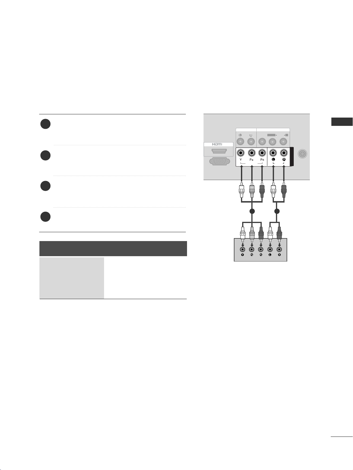
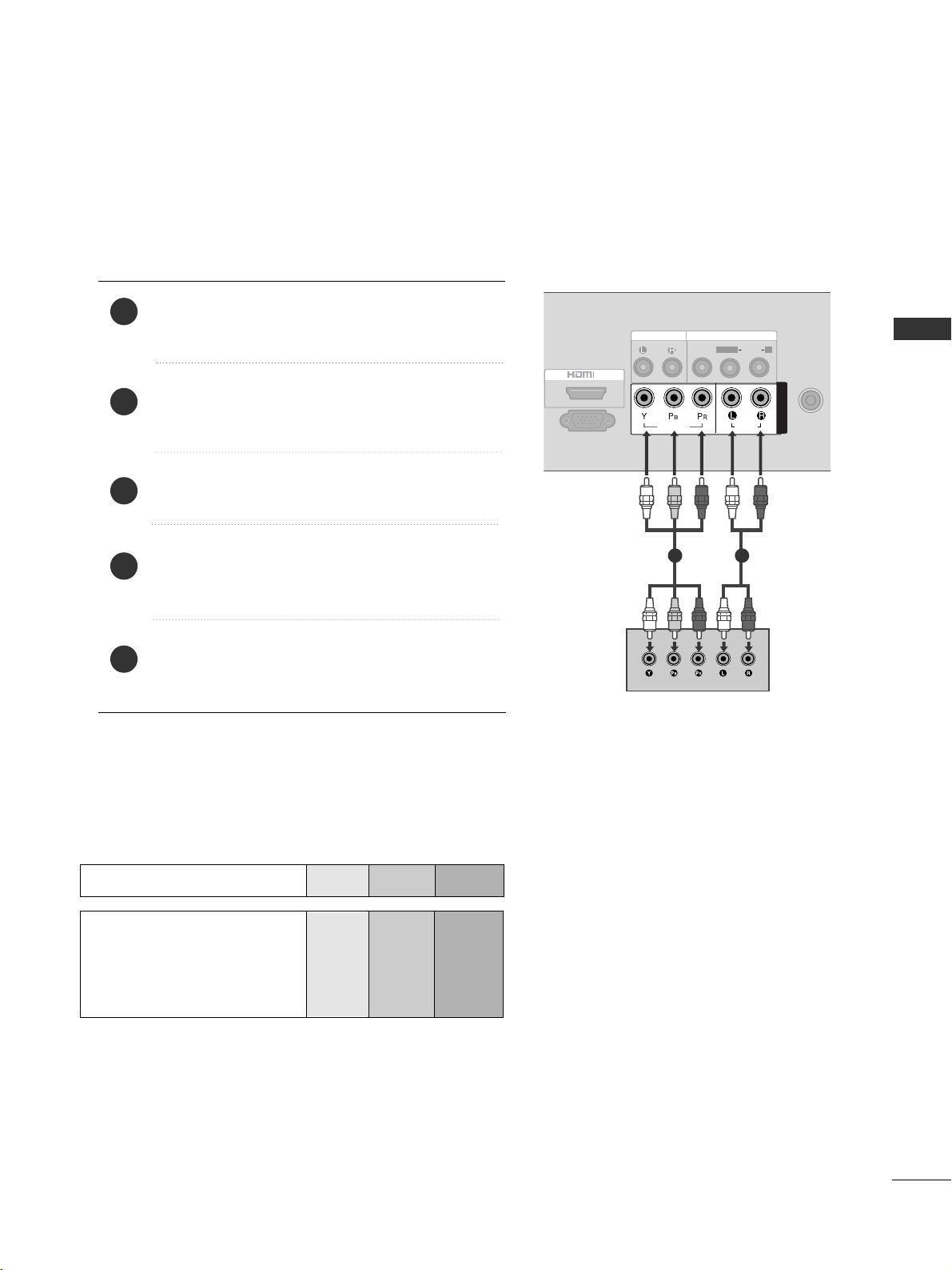
HD RECEIVER SETUP
Connecting with a component cable
Connect the video outputs (Y, P
B, PR
)
of the digi-
tal set-top box to the
CCOOMMPPOONNEENNTT IINN VVIIDD EEOO
jacks on the TV.
Connect the audio output of the digital set-top
box to the
CCOOMMPPOONNEENNTT IINN AAUUDDIIOO
jacks on
the TV.
Turn on the digital set-top box.
(
Refer to the owner’s manual for the digital set-top
box.
)
Select
CCoommppoo nnee nntt
input source using the
IINNPPUUTT
button on the remote control.
2
3
4
1
Signal
480i/576i
480p/576p
720p
1080i/ 1080p
Component
O
O
O
X
Page 16
14
EXTERNAL EQUIPMENT SETUP
EXTERNAL EQUIPMENT SETUP
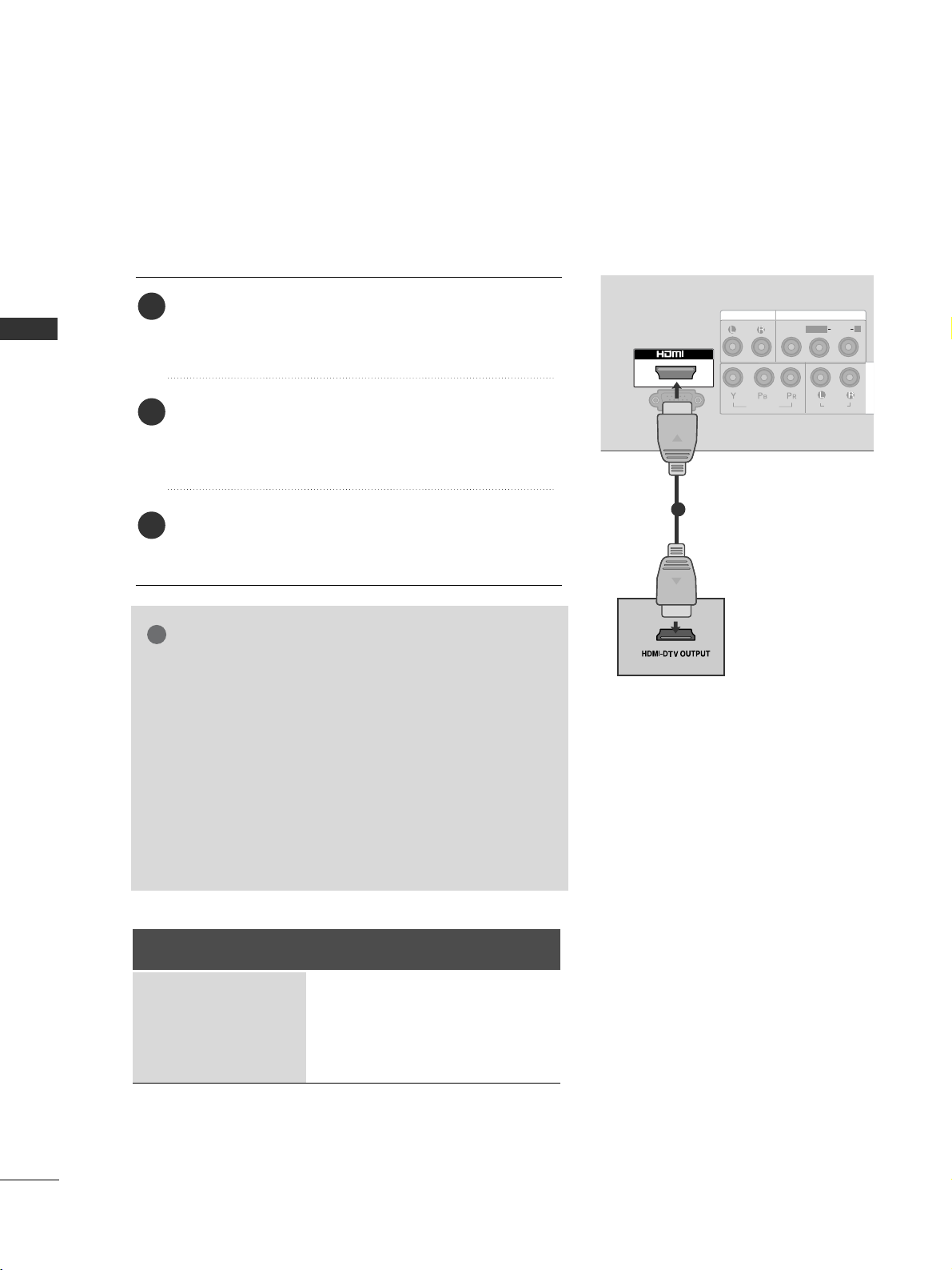
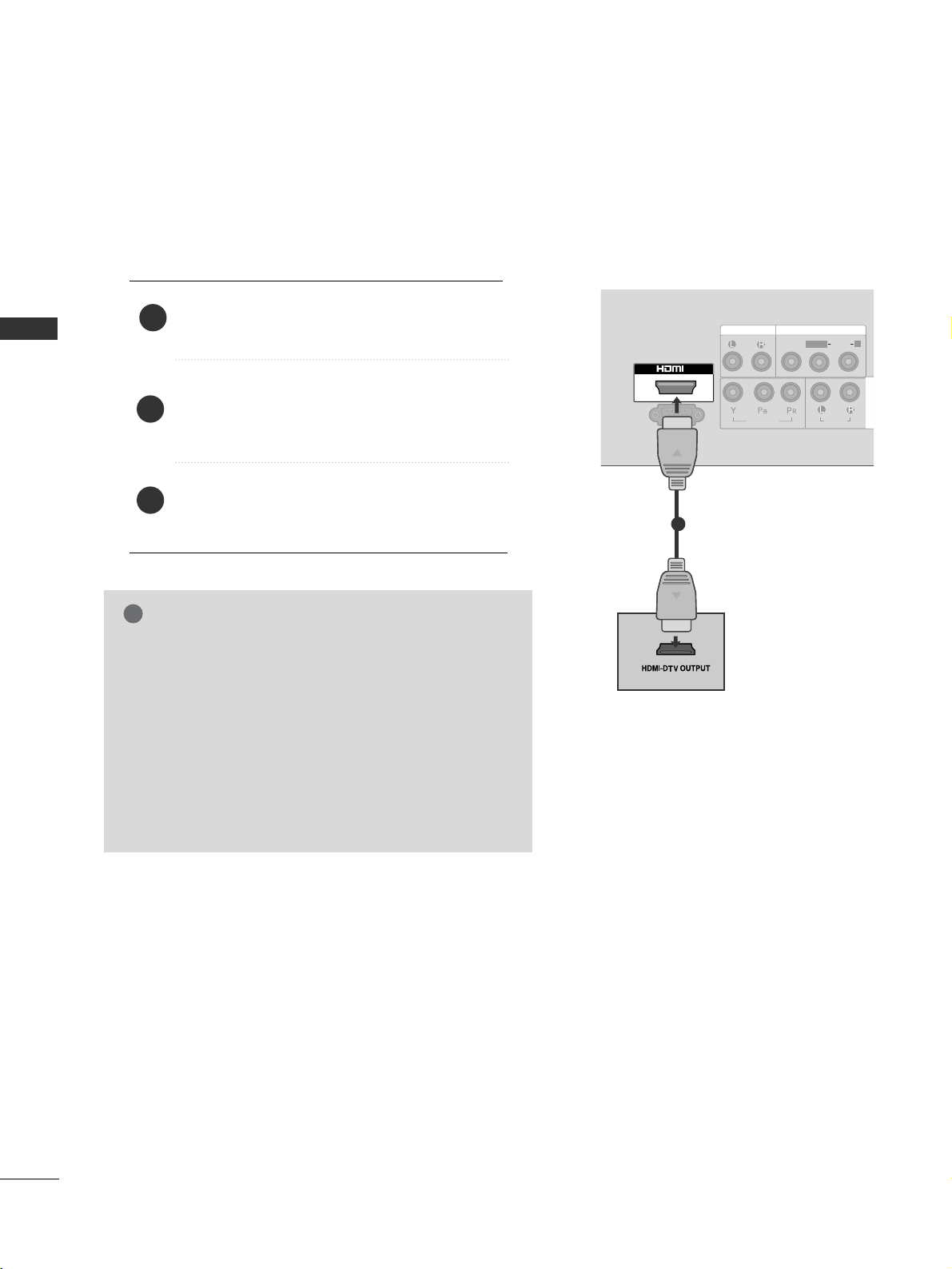
Connecting a set-top box with a HDMI cable
Connect the HDMI output of the digital set-top box to
the
HH DDMMII IINN
jack on the TV.
Select
HHDDMMII
input source using the
IINNPPUUTT
button on
the remote control.
Turn on the digital set-top box.
(
Refer to the owner’s manual for the digital set-top box.
)
2
3
1
GG
TV can receive the video and audio signal simultaneously
with using a HDMI cable.
GG
If the digital set-top box supports Auto HDMI function,
the output resolution of the source device will be automatically TV to 1280x720p.
GG
If the digital set-top box player does not support Auto
HDMI, you need to TV the output resolution appropriately.
To get the best picture quality, adjust the output resolution of the source device to 1280x720p .
GG
We recommend less than 10m for HDMI cable.
NOTE
!
L/MONO
R
AUDIO
VIDEO
VARIABLE AUDIO OUT
HDMI IN HDMI DVI IN
HDMI/DVI IN
1
IN
SERVICE ONLY
AUDIO OUT
VIDEO
AUDIO
L(MONO)
R
AV IN
AUDIO
VIDEO
COMPONENT IN
1
Signal
480i/576i
480p/576p
720p
1080i/ 1080p
HDMI
X
O
O
X
Page 17
15
DVD SETUP
EXTERNAL EQUIPMENT SETUP
Connecting with a component cable
Component Input ports
To achieve better picture quality, connect a DVD player to
the component input ports as shown below.
Component ports on the TV
YPB PR
Video output ports
on DVD player
Y
Y
Y
Y
PB
B-Y
Cb
Pb
PR
R-Y
Cr
Pr
Connect the video outputs (Y, PB, P
R
)
of the DVD to
the
CCOOMMPPOONNEENNTT IINN VVIIDDEEOO
jacks on the TV.
Connect the audio outputs of the DVD to the
CCOOMMPPOONNEENN TT IINN AAUUDDIIOO
jacks on the TV.
Turn on the DVD player, insert a DVD.
Select
CCoommpp oonn eenn tt
input source using the
IINNPP UUTT
button on the remote control.
Refer to the DVD player's manual for operating
instructions.
2
3
4
5
1
IN
SERVICE ONLY
ANTENNA
IN
AUDIO OUT
VIDEO
AUDIO
L(MONO)
R
AV IN
AUDIO
VIDEO
COMPONENT INCOMPONENT IN
1 2
Page 18
16
EXTERNAL EQUIPMENT SETUP
EXTERNAL EQUIPMENT SETUP
Connecting with a HDMI cable
Connect the HDMI output of the DVD to the
HH DDMM II IINN
jack on the TV.
Select
HHDDMM II
input source using the
IINNPP UU TT
button on the remote control.
Refer to the DVD player's manual for operating
instructions.
1
GG
The TV can receive video and audio signals simultaneously when using a HDMI cable.
GG
If the DVD player supports Auto HDMI function, the
output resolution of the source device will be automatically TV to 1280x720p.
GG
If the DVD player does not support Auto HDMI, you
must TV the output resolution appropriately.
To get the best picture quality, adjust the output resolution of the source device to 1280x720p.
GG
We recommend less than 10m for HDMI cable.
NOTE
!
2
3
L/MONO
R
AUDIO
VIDEO
VARIABLE AUDIO OUT
HDMI IN HDMI DVI IN
HDMI/DVI IN
1
IN
SERVICE ONLY
AUDIO OUT
VIDEO
AUDIO
L(MONO)
R
AV IN
AUDIO
VIDEO
COMPONENT IN
1
Page 19
17
VCR SETUP
EXTERNAL EQUIPMENT SETUP
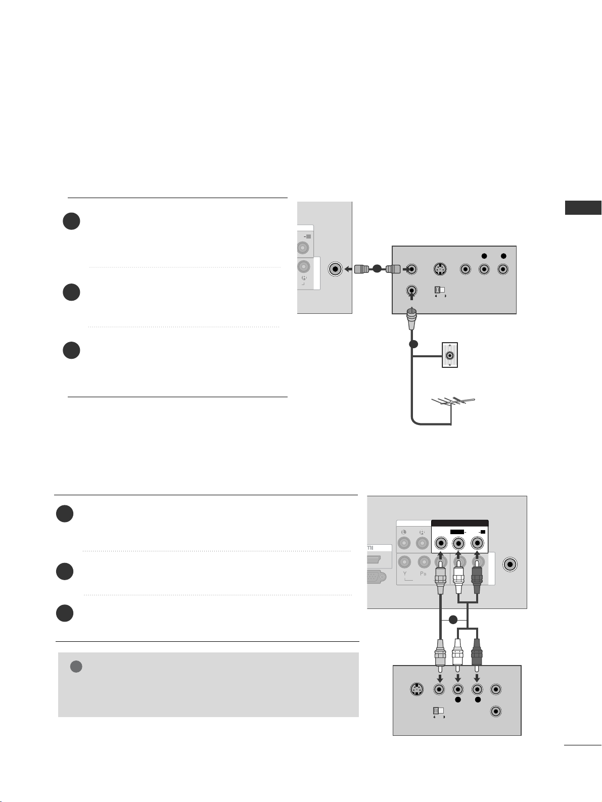
■
To avoid picture noise (interference), allow adequate distance between the VCR and TV.
Connect the
AA NNTT OO UU TT
socket of the
VCR to the
AANNTT EENNNNAA IINN
socket on the
TV.
Connect the antenna cable to the
AA NNTT IINN
socket of the VCR.
Press the
PP LLAAYY
button on the VCR and
match the appropriate programme
between the TV and VCR for viewing.
2
3
1
Connecting with a RF cable
ANTENNA
IN
DIO
R
IO
COMPONENT IN
OUTPUT
SWITCH
ANT IN
R
S-VIDEO VIDEO
ANT OUT
L
Wall Jack
Antenna
1
2
Connecting with a RCA cable
Connect the
AA UUDDIIOO/VV II DD EE OO
jacks between TV and VCR.
Match the jack colours (Video = yellow, Audio Left = white, and
Audio Right = red)
Insert a video tape into the VCR and press PLAY on the VCR.
(
Refer to the VCR owner’s manual.
)
Select
AA VV
input source using the
IINNPP UUTT
button on the
remote control.
1
2
3
GG
If you have a mono VCR, connect the audio cable from the VCR
to the
AAUUDDIIOO LL//MMOO NNOO
jack of the TV.
NOTE
!
AV IN 2
IN
ANTENNA
IN
AUDIO OUT
AUDIO
VIDEO
COMPONENT IN
AV IN
L
R
S-VIDEO
VIDEO
OUTPUT
SWITCH
ANT IN
ANT OUT
VIDEO
AUDIO
L(MONO)
R
1
Page 20

18
EXTERNAL EQUIPMENT SETUP
EXTERNAL STEREO SETUP
Use to connected either an external amplifier, or add a subwoofer to your surround sound system.
Connect the input jack of the stereo amplifier to the
AAUUDD IIOO OO UUTT
jacks on the TV.
Set up your speakers through your analog stereo
amplifier, according to the instructions provided with
the amplifier.
2
1
L/MONO
R
AUDIO
VIDEO
VARIABLE
AUDIO OUT
IN
SERVICE ONLY
AUDIO
VIDEO
COMPONENT IN
VIDEO
AUDIO
L(MONO)
R
AUDIO OUT
AV IN
11
EXTERNAL EQUIPMENT SETUP
OTHER A/V SOURCE SETUP
Connect the
AA UUDDIIOO/VV II DD EE OO
jacks between TV
and external equipment. Match the jack colours
.
(
Video = yellow, Audio Left = white, and Audio Right
= red
)
Select
AA VV
input source using the
IINNPP UUTT
button
on the remote control.
If connected to
AA VV IINN
, select
AA VV
input source.
Operate the corresponding external equipment.
Refer to external equipment operating guide.
1
2
3
IN
SERVICE ONLY
ANTENNA
IN
AUDIO OUT
AUDIO
VIDEO
COMPONENT IN
AV IN
L R
VIDEO
VIDEO
AUDIO
L(MONO)
R
Camcorder
Video Game Set
1
GG
This function works in following mode : TV, AV, Component, HDMI
NOTE
!
Page 21

19
EXTERNAL EQUIPMENT SETUP
Supported Display Resolution
HDMI-DTV mode
31.47 59.94
31.5 60.00
31.25 50.00
44.96 59.94
45 60 .0 0
37.50 50.00
Resolution
720x480
720x576
1280x720
Horizontal Vertical
Frequency(kHz) Frequency(Hz)
GG
HDMI mode supports PCM audio format only.
GG
If the Audio setting is set to Dolby/DTS/Bitstream in some DVDP/STB, make sure to change the setting
to PCM.
GG
If the resolution of external equipment is over 1280x720p, there will be no picture on the TV.
NOTE
!
Page 22

WATCHING TV / PROGRAMME CONTROL
20
WATCHING TV / PROGRAMME CONTROL
REMOTE CONTROL KEY FUNCTIONS
When using the remote control, aim it at the remote control sensor on the TV.
RATIO
POWER
TV
INPUT
Switches the set on from standby or off to standby.
Returns to the TV viewing from any mode.
If you press the button once, the input source OSD will
appear on screen as shown. Press the
DD/ EE
button and
then OK button to select the desired input source.
MUTE
PSM
SSM
I/II
Switches the sound on or off.
Recalls your preferred picture setting.
Recalls your preferred sound setting.
Selects the sound output. (
GG
pp ..4466
)
0~9 number
button
Selects a programme.
Selects numbered items in a menu.
LIST
Q.VIEW
Displays the programme table.
Returns to the previously viewed programme.
Page 23

WATCHING TV / PROGRAMME CONTROL
21
RATIO
THUMBSTICK
(Up/Down/Left/
Right)
OK
Allows you to navigate the on-screen menus and adjust
the system settings to your preference.
Adjusts the volume.
Selects a programme.
Accepts your selection or displays the current mode.
MENU
SLEEP
RATIO
Selects a menu.(
GG
pp ..2233
)
Sets the sleep timer.
Selects your desired picture format.(
GG
pp ..3333
)
Coloured
buttons
TELETEXT
BUTTONS
These buttons are used for teletext (on
TT EELLEETT EEXX TT
models only) or
PPrroogg rr aammmmee eedd iitt
.
These buttons are used for teletext.
For further details, see the ‘Teletext’ section. (
GG
pp ..5522
)
Installing Batteries
■
Open the battery compartment cover on the back side and install the
batteries matching correct polarity (+with +,-with -).
■
Install two 1.5V AAA batteries. Don’t mix old or used batteries with
new ones.
■
Close cover.
Page 24

WATCHING TV / PROGRAMME CONTROL
WATCHING TV / PROGRAMME CONTROL
22
Press the
F
//
G
button to adjust the volume.
If you wish to switch the sound off, press the
MMUUTT EE
button.
You can cancel the Mute function by pressing the
MMUUTT EE
,
F
//
G
, SSM
or
I/II button.
PROGRAMME SELECTION
TURNING ON THE TV
When your TV is turned on, you will be able to use its features.
Firstly, connect the power cord correctly.
At this stage, the TV switches to standby mode.
■
In standby mode to turn TV on, press the button on the TV or press the
PP OOWWEE RR
buttons on the remote control and the TV will switch on.
1
VOLUME ADJUSTMENT
Press the
DD
//
EE
or
NNUUMMBBEERR
buttons to select a programme number.
2
3
1
1
1
Installation Guide
Note:
a. It will automatically disappear after approx. 40 seconds unless a button is pressed.
b. If you close without completing the initial setting, the
IInnss ttaa ll llaa ttiioo nn GG uuiidd ee
menu can be displayed
again.
If the OSD (On Screen Display) is displayed on the screen after turning on the TV, you can adjust the
LLaa nn gguuaa gg ee, AAuuttoo TTuunniinngg
.
Page 25

WATCHING TV / PROGRAMME CONTROL
23
DEF G OK MENU
ON SCREEN MENUS SELECTION AND ADJUSTMENT
Press the
MMEENN UU
button and then D
//
EE
button to display each menu.
Press the
G button and then D
//
EE
button to select a menu item.
Change the setting of an item in the sub or pull-down menu with
F
//
G button.
You can move to a higher level menu by pressing the
OO KK
button.
Your TV's OSD (On Screen Display) may differ slightly from that shown in this manual.
NOTE
!
a. The OSD (On Screen Display) function enables you to adjust the screen status conveniently since it
provides graphical presentation.
b. In this manual, the OSD (On Screen Display) may be different from your TV’s because it is just
example to help the TV operation.
c. In the teletext mode, menus are not displayed.
Setup MENU
Picture MENU
Audio MENU
Time MENU
Option MENU
1
2
3
Clock
Off Time
On Time
Sleep Timer
Time
Auto Tuning
Manual Tuning
Programme Edit
Favourite Programme
Setup
Sound Mode
• Treble 50
• Bass 50
• Reset
Auto Volume
Balance 0
Audio
Language
Key Lock
Power Indicator
Factory Reset
Option
Aspect Ratio
Picture Mode
• Backlight 100
• Contrast 100
• Brightness 50
• Sharpness 70
• Colour 70
• Tint 0
Picture
DEF G OK MENU
DEF G OK MENU
DEF G OK MENU
DEF G OK MENU
E
Page 26

WATCHING TV / PROGRAMME CONTROL
WATCHING TV / PROGRAMME CONTROL
24
Press the
MMEENNUU
button and then
DD
//
EE
button to select the
SSeettuupp
menu.
Press the
GG
button and then
DD
//
EE
button to select
AAuuttoo
TTuunniinngg
.
Press the
GG
button and then
DD
//
EE
button to select
SSyysstteemm
.
Press the
GG
button and then
DD
//
EE
button to select a TV
system menu;
BG: PAL B/G, SECAM B/G (Asia / NewZealand / M.East / Africa)
I : PAL I/II (South Africa / Hong Kong)
DK: PAL D/K, SECAM D/K (China / Africa / CIS)
M : (Philippines)
Press the
DD
//
EE
button to select
SSttoorraaggee FFrroomm
.
Press the
FF
//
GG
button or NUMBER buttons to select the ini-
tial programme number.
Press the
DD
//
EE
button to select
SSeeaarrcchh
.
Press the
GG
button to begin auto tuning.
All receivable stations are stored.
To stop auto tuning, press the
MMEENN UU
button.
When auto tuning is complete, the Programme edit menu
appears on the screen. See the Programme edit section to edit
the stored programme.
Press the
MMEE NNUU
button to move to the previous menu
screen.
1
2
3
4
5
6
7
8
9
Up to 200 TV stations can be stored by programme numbers (0 to 199). Once you
have preset the stations, you will be able to use the
DD
//
EE
or NUMBER buttons to
scan the stations you have programmed.
Stations can be tuned using automatic or manual modes.
All stations which can be received are stored by this method. It is
recommended that you use Auto tuning during installation of this TV.
AUTO PROGRAMME TUNING
Auto Tuning
System
Storage From
Search
System G
2
Setup
Auto Tuning
Manual Tuning
Programme Edit
Favourite Programme
To Set
Auto Tuning G
3 4 5 6
7
8
Auto Tuning
C 05 BG
5 35%
BG
I
DK
M
1
Auto Tuning
Manual Tuning
Programme Edit
Favourite Programme
Setup
DEF G OK MENU
DEF G OK MENU
DEF G OK MENU
Menu Stop
Page 27

WATCHING TV / PROGRAMME CONTROL
25
MANUAL PROGRAMME TUNING
Press the
MMEENN UU
button and then
DD
//
EE
button to select
the
SS ee ttuupp
menu.
Press the
GG
button and then
DD
//
EE
button to select
MMaannuu aall TT uunniinngg
.
Press the
GG
button and then
DD
//
EE
button to select
SSttoorraaggee
.
Press the
FF
//
GG
button or NUMBER buttons to select the
desired programme number (0 to 199).
Press the
DD
//
EE
button to select
SSyyss ttee mm
.
Press the
GG
button and then
DD
//
EE
button to select a TV
system menu;
BG: PAL B/G, SECAM B/G (Asia / NewZealand / M.East / Africa)
I : PAL I/II (South Africa / Hong Kong)
DK: PAL D/K, SECAM D/K (China / Africa / CIS)
M : (Philippines)
Press the
DD
//
EE
button to select
BB aanndd
.
Press the
GG
button and then
DD
//
EE
button to select
VV //UUHH FF
or
CCaabb llee
.
Press the
DD
//
EE
button to select
CChh aann nnee ll
.
Press the
GG
button and then You can select the desired pro-
gramme number with the
FF
//
GG
button or NUMBER buttons. If possible, select the programme number directly with
the number buttons.
Press the
DD
//
EE
button to select
SSee aarrcc hh
.
Press the
FF
//
GG
button to commence searching. If a sta-
tion is found the search will stop.
Press the
OO KK
button to store it.
To store another station, repeat steps 33to
11 33
.
Press the
MMEE NNUU
button to move to the previous menu
screen.
Manual Turning lets you manually tune and arrange the stations in
whatever order you desire.
1
2
3
4
5
6
7
8
9
10
11
12
13
14
15
73 4 5 6
8 9
10 11 12
1
Auto Tuning
Manual Tuning
Programme Edit
Favourite Programme
Setup
2
Setup
Auto Tuning
Manual Tuning
Programme Edit
Favourite Programme
To Set
Manual Tuning G
Manual Tuning
Storage
System
Band
Channel
Fine
Search
Name
Storage G
1
DEF G OK MENU
DEF G OK MENU
DEF G OK MENU
Page 28

WATCHING TV / PROGRAMME CONTROL
WATCHING TV / PROGRAMME CONTROL
26
FINE TUNING
Press the
MMEENN UU
button and then
DD
//
EE
button to select
the
SSeettuupp
menu.
Press the
GG
button and then
DD
//
EE
button to select
MMaannuu aall TT uunniinngg
.
Press the GGbutton and then
DD
//
EE
button to select
FFii nnee
.
Press the
GG
button and then
FF
//
GG
button to fine tune for
the best picture and sound.
Press the
OO KK
button to store it.
Press the
MMEE NNUU
button to move to the previous menu
screen.
1
2
3
4
5
6
Normally fine tuning is only necessary if reception is poor.
3 4 5
1
Auto Tuning
Manual Tuning
Programme Edit
Favourite Programme
Setup
2
Setup
Auto Tuning
Manual Tuning
Programme Edit
Favourite Programme
To Set
Manual Tuning G
Manual Tuning
Storage
System
Band
Channel
Fine
Search
Name
Fine G
F /G
DEF G OK MENU
DEF G OK MENU
DEF G OK MENU
Page 29

WATCHING TV / PROGRAMME CONTROL
27
ASSIGNING A STATION NAME
You can assign a station name up to five characters to each programme number.
Press the
MMEENN UU
button and then
DD
//
EE
button to select
the
SSeettuupp
menu.
Press the
GG
button and then
DD
//
EE
button to select
MMaannuu aall TT uunniinngg
.
Press the GGbutton and then
DD
//
EE
button to select
NNaa mmee
.
Press the
GG
button and then
DD
//
EE
button. You can use a
blank, ++, --, the number 00to 99and the alphabet AAto ZZ.
Press the
FF
//
GG
button to select the position and make
your choice of the second character, and so on.
Press the
OO KK
button to store it.
Press the
MMEE NNUU
button to move to the previous menu
screen.
1
2
3
4
5
6
7
3 4 5 6
1
Auto Tuning
Manual Tuning
Programme Edit
Favourite Programme
Setup
2
Setup
Auto Tuning
Manual Tuning
Programme Edit
Favourite Programme
To Set
Manual Tuning G
Manual Tuning
Storage
System
Band
Channel
Fine
Search
Name
Name G
- - - - -
DEF G OK MENU
DEF G OK MENU
DEF G OK MENU
Page 30

WATCHING TV / PROGRAMME CONTROL
WATCHING TV / PROGRAMME CONTROL
28
PROGRAMME EDIT
This function enables you to delete or skip stored programmes.
Also you can move some stations to other programme numbers.
Press the
MMEENN UU
button and then
DD
//
EE
button to select
the
SSeettuupp
menu.
Press the
GG
button and then
DD
//
EE
button to select
PPrroogg rr aammmmee EEddii tt
.
Press the GGbutton to display the
Programme edit menu.
AA
DDeelleettiinngg aa pprrooggrraammmmee
1.Select a programme to be deleted with the
DD
//
EE
//
FF
//
GG
button.
2.Press the RED button twice.
The selected programme is deleted, all the following
programmes are shifted up one position.
AA
MMoovviinngg aa pprrooggrraammmmee
1.Select a programme to be moved with the
DD
//
EE
//
FF
//
GG
button.
2.Press the Green button.
3.Move the programme to the desired programme number with
the
DD
//
EE
//
FF
//
GG
button.
4.Press the Green button again to release this function.
AA
SSkkiippppiinngg aa pprrooggrraammmmee nnuummbbeerr
1.Select a programme number to be skipped with the
DD
//
EE
//
FF
//
GG
button.
2.Press the BLUE button. The skipped programme turns to blue.
3.Press the BLUE button again to release the skipped programme.
When a programme number is skipped it means that you will
be unable to select it using the
DD
//
EE
button during normal
TV viewing. If you wish to select the skipped programme,
directly enter the programme number with the NUMBER buttons or select it in the programme edit or table menu.
Press the
MMEE NNUU
button to move to the previous menu
screen.
1
2
3
4
3
Programme Edit
Delete
Move Skip
0C03 5S69
1 BLN 03 6 S 17
2 C 12 7 S 22
3 S 66 8 C 09
4 S 67 9 C 11
1
Auto Tuning
Manual Tuning
Programme Edit
Favourite Programme
Setup
2
Setup
Auto Tuning
Manual Tuning
Programme Edit
Favourite Programme
To Set
Programme Edit G
DEF G OK MENU
DEF G OK MENU
DEF G OK MENU
Page 31

WATCHING TV / PROGRAMME CONTROL
29
FAVOURITE PROGRAMME
Press the
MMEENNUU
button and then
DD
//
EE
button to select the
SSeettuupp
menu.
Press the
GG
button and then
DD
//
EE
button to select
FFaavvoouurriittee PPrrooggrraammmmee
.
Press the
GG
button.
Press the
DD
//
EE
button to select - - - - - - - -.
Select a desired programme with the
FF
//
GG
button or NUM-
BER buttons.
To store another programme, repeat steps
44
to 55.
You can store up to 8 programmes.
Press the
MMEE NNUU
button to move to the previous menu
screen.
This function lets you select your favourite programmes directly.
Repeatedly press the YELLOW button to select stored favourite
programmes.
1
2
3
4
5
6
7
1
2 3 4 5
Auto Tuning
Manual Tuning
Programme Edit
Favourite Programme
Setup
Setup
Auto Tuning
Manual Tuning
Programme Edit
Favourite Programme
--- -----
--- -----
--- -----
--- -----
--- -----
--- -----
--- -----
--- -----
Favourite Programme G
DEF G OK MENU
DEF G OK MENU
Page 32

WATCHING TV / PROGRAMME CONTROL
WATCHING TV / PROGRAMME CONTROL
30
SELECTING THE PROGRAMME LIST
You can check which programmes are stored in the memory by displaying the programme list.
AA
DDii sspp llaa yyiinngg pp rroogg rraa mmmmee ll iisstt
Press the
LL IISS TT
button to display the
PP rroo gg rraamm mmee
LL ii sstt
menu.
The programme
list
appears on the screen.
One programme
list
contains ten programmes as shown.
AA
SS eelleeccttiinngg aa pprrooggrraa mmmmee ii nn tthhee pprrooggrraa mmmmee lliisstt
Select a programme with the
DD
//
EE
//
FF
//
GG
button.
Then press the
OO KK
button. The TV switches to the chosen
programme number.
AA
PP aaggiinngg tthhrroouugghh aa pprroogg rraa mmmmee ll iisstt
There are 20 programme table pages in which contain 200 pro
grammes. Pressing the
DD
//
EE
//
FF
//
GG
button repeatedly turns the
pages.
Press the
LL IISSTT
button to return to normal TV viewing.
NOTE
!
a. You may find some blue programmes. They have been set up
to be skipped by auto programming or in the programme edit
mode.
b. Some programmes with the channel number shown in the
programme list indicate there is no station name assigned.
Programme List
0C03 5S69
1 BLN 03 6 S 17
2 C 12 7 S 22
3 S 66 8 C 09
4 S 67 9 C 11
DEF G OK
Page 33

WATCHING TV / PROGRAMME CONTROL
31
KEY LOCK
NOTE
!
GG
In
KKeeyy LLoo cckk ‘OO nn
’, if the TV is turned off, press the
rr // II
button on the TV or
PPOOWW EE RR
buttons on
the remote control.
GG
With the
KKeeyy LLoocckk OO nn
, the display ‘
KK eeyy LLoocckk OO nn
’ appears on the screen if any button on the front
panel is pressed while viewing the TV.
The TV can be set so that the remote control is needed to control it.
This feature can be used to prevent unauthorized viewing.
This TV is programmed to remember which option it was last
set to even if you turn the TV off.
Press the
MMEENN UU
button and then
DD
//
EE
button to select
the
OOpptt ii oonn
menu.
Press the
GG
button and then
DD
//
EE
button to select
KK ee yy
LL oocc kk
.
Press the
GG
button and then
DD
//
EE
button to select
OO nn
or
OO ff ff
.
Press the
MMEE NNUU
button to move to the previous menu
screen.
1
2
3
4
32
Option
Language
Key Lock
Power Indicator
Factory Reset
Key Lock G Off
On
1
Language
Key Lock
Power Indicator
Factory Reset
Option
DEF G OK MENU
DEF G OK MENU
Page 34

WATCHING TV / PROGRAMME CONTROL
WATCHING TV / PROGRAMME CONTROL
32
Use to quickly reset all the menu options to their original
factory preset values.
This function deletes all TV programmes.
When the
FFaacc ttoorryy RR ee ss ee tt
is completed, you must
restart the
II nnssttaallllaattiioonn GG uuiiddee
.
3
2
Option
Language
Key Lock
Power Indicator
Factory Reset
Factory Reset G
1
To set
FACTORY RESET
Press the
MMEENN UU
button and then
DD
//
EE
button to
select the
OOpptt ii oo nn
menu.
Press the
GG
button and then
DD
//
EE
button to select
FFaacctt oo rr yy RR ee ss ee tt
.
Press the
GG
button and then
FF
//
GG
button to select
YY eess
or
NN oo
.
Press the
MMEE NNUU
button to move to the previous menu
screen.
1
2
3
4
Factory Reset
Yes
No
Language
Key Lock
Power Indicator
Factory Reset
Option
DEF G OK MENU
DEF G OK MENU
F G OK MENU
Page 35

PICTURE CONTROL
33
PICTURE CONTROL
PICTURE SIZE (ASPECT RATIO)CONTROL
You can watch the screen in various picture formats;
1166::99,, OOrriiggiinnaall, 44::33, 1144 ::99
,
ZZoooo mm11,ZZoooo mm22
and
JJ uu ss tt SS ccaann
.
If a fixed image is displayed on the screen for a long time, that fixed image may
become imprinted on the screen and remain visible.
You can adjust the enlarge proportion using
DD EE
button.
This function works in the following signal.
•
1166 ::99
The following selection will allow you to adjust the
picture horizontally, in linear proportion, to fill the
entire screen(useful for viewing 4:3 formatted DVDs).
•
OOrr ii gg iinn aall
When your TV receives a wide screen signal it will
automatically change to the picture format to be
broadcast.
•
44:: 33
The following selection will allow you to view a picture with an original 4:3 aspect ration, black bars
will appear on both the left and right of the
screen.
•
1144::99
You can view a picture format of 14:9 or a general TV
programme in the 14:9 mode. The 14:9 screen is
viewed in the same way as in 4:3, but is magnified to
the left and right.
•
ZZoo oomm11
The following selection will allow you to view
the picture without any alteration, while filling
the entire screen. However, the top and bottom of the picture will be cropped.
•
ZZoo oomm22
Choose Zoom 2 when you wish the picture to
be altered, both horizontally extended and
vertically cropped. The picture adopting a
compromise between alteration and screen
converage.
•
JJuusstt SS ccaann
Following Selection will lead to you view the
picture of best quality without loss of original
picture in high resolution image.
Note : If there is noise in original Picture, You
can see the noise at the edge.
You can adjust
AAssppeecctt RRaattiioo
in the
PPiiccttuurree
menu.
1
16:9
Original
4:3
14:9
DE
Zooml
DE
Zoom2
DE
NOTE
!
GG
You can only select 4:3,16:9 (Wide) in
Component, HDMI mode.
GG
In HDMI/Component (over 720p)mode, Just
Scan is available.
Just Scan
Page 36

PICTURE CONTROL
PICTURE CONTROL
34
PRESET PICTURE SETTINGS
Picture Mode adjusts the TV for the best picture appearance. Select the
preset value in the
PPii ccttuurree MMoo ddee
menu based on the programme
category.
VV iivv iidd, SSttaa nnddaarrdd
and
CCiinn eemmaa
are programmed for optimum picture
reproduction at the factory and cannot be changed.
Press the
MMEENN UU
button and then
DD
//
EE
button to select
the
PPii cctt uu rr ee
menu.
Press the
GG
button and then
DD
//
EE
button to select
PPii cctt uu rr ee MMooddee
.
Press the
GG
button and then
DD
//
EE
button to select
VViivviidd,,
SSttaannddaarrdd orCCiinneemmaa
.
Press the
MMEE NNUU
button to move to the previous menu
screen.
Picture Mode-Preset
1
2
3
4
1
32
Picture
Aspect Ratio
Picture Mode
• Backlight 100
• Contrast 100
• Brightness 50
• Sharpness 70
• Colour 70
• Tint 0
Picture Mode G
Vivid
Standard
Cinema
DEF G OK MENU
Aspect Ratio
Picture Mode
• Backlight 100
• Contrast 100
• Brightness 50
• Sharpness 70
• Colour 70
• Tint 0
Picture
DEF G OK MENU
E
E
Page 37

PICTURE CONTROL
35
MANUAL PICTURE ADJUSTMENT
Press the
MMEENN UU
button and then
DD
//
EE
button to select
the
PPii cctt uu rr ee
menu.
Press the GGbutton and then
DD
//
EE
button to select
PPii cctt uu rr ee MMooddee
.
Press the
GG
button and then
DD
//
EE
button to select
VViivviidd,,
SSttaannddaarrdd orCCiinneemmaa
.
Press the
OO KK
button and then
DD
//
EE
button to select the
desired picture option (
BB aacckklliigghhtt, CCoonnttrr aasstt
,
BB rr ii gg hhttnn eess ss
,
SShhaarrppnn ee ss ss, CCoolloo uu rr
and
TT iinn tt
).
Press the
FF
//
GG
button to make appropriate adjustments.
Press the
MMEE NNUU
button to move to the previous menu
screen.
Picture Mode-User Option
BB aa cckklliigg hhtt
To control the brightness of the screen, adjust
the brightness of LCD panel.
CCoo nntt rraass tt
Adjusts the difference between light and dark
levels in the picture.
BB rriigghhttnn ee ss ss
Increases or decreases the amount of white in
the picture.
SShh aarrpp nneessss
Adjusts the level of crispness in the edges
between the light and dark areas of the picture.
The lower the level, the softer the image.
CCoo lloo uurr
Adjusts intensity of all colours.
TT ii nntt
Adjusts the balance between red and green
levels.
1
2
3
4
5
6
54
•
Backlight 100 F
G
E
E
1
32
Aspect Ratio
Picture Mode
• Backlight 100
• Contrast 100
• Brightness 50
• Sharpness 70
• Colour 70
• Tint 0
Picture
DEF G OK MENU
Picture
Aspect Ratio
Picture Mode
• Backlight 100
• Contrast 100
• Brightness 50
• Sharpness 70
• Colour 70
• Tint 0
Picture Mode G
Vivid
Standard
Cinema
DEF G OK MENU
Picture
Aspect Ratio
Picture Mode
• Backlight 100
• Contrast 100
• Brightness 50
• Sharpness 70
• Colour 70
• Tint 0
• Backlight 100
G
DEF G OK MENU
Vivid
E
E
E
Page 38

PICTURE CONTROL
PICTURE CONTROL
36
PICTURE IMPROVEMENT TECHNOLOGY
Press the MENU button and then
DD
//
EE
button to select
the
PPii cctt uu rr ee
menu.
Press the
GG
button and then
DD
//
EE
button to select
AAddvvaa nncceedd
.
Press the GGbutton and then
DD
//
EE
button to select
DD yynnaammii cc CCoonntt rr aasstt,DD yynnaamm ii cc CCoolloo uu rr,NNoo iissee
RR ee dduuccttiioo nn,BB llaacckk LL eevvee ll,FFiillmm MM oo ddee orCCoolloo uu rr
TTee mm ppeerraa ttuurree
.
Press the
MMEE NNUU
but
ton to move to the previous menu
screen.
You can calibrate the screen for each Picture Mode or set the
video value according to the special video screen.
You can set the video value differently for each input.
To reset to the factory default screen after making adjustments to
each video mode, execute the “Picture Reset” function for each
Picture Mode.
1
2
3
4
1
3
2
Picture Mode
• Backlight 100
• Contrast 100
• Brightness 50
• Sharpness 70
• Colour 70
• Tint 0
• Advanced
Picture
DEF G OK MENU
E
Advanced
Dynamic Contrast G
Dynamic Colour
Noise Reduction
Black Level
Film Mode
Colour Temperature
• Red 0
• Green 0
Dynamic Contrast G
Off
Low
High
Picture
Picture Mode
• Backlight 100
• Contrast 100
• Brightness 50
• Sharpness 70
• Colour 70
• Tint 0
• Advanced
• Advanced
G
To Set
E
E
E
E
DEF G OK MENU
DEF G OK MENU
Page 39

PICTURE CONTROL
37
DD yynnaamm iicc CCoo nnttrraa ss tt
((OOff ff //LL ooww// HHii gghh))
■
Adjusts the contrast to keep it at the best level according to the
brightness of the screen. The picture is improved by making bright
parts brighter and dark parts darker.
DD yy nnaa mm iicc CCoo lloouurr
((OOff ff //LL ooww// HHii gghh))
■
Adjusts screen colours so that they look livelier, richer and clearer.
This feature enhances hue, saturation and luminance so that red,
blue, green and white look more vivid.
NNoo iiss ee RR eedduucc ttiioo nn
((OOff ff //LL ooww// HHii gghh))
■
Reduces screen noise without compromising video quality.
BB llaacc kk LLeevveell
((LLooww //HHii gghh))
•
Low :The reflection of the screen gets darker.
• High : The reflection of the screen gets brighter.
■
Set black level of the screen to proper level.
■
This function enables to select ‘Low’ or ‘High’ in the following
mode: RF, AV, Component or HDMI.
FFiillmm MMoodd ee
((OOnn//OOffff))
■
Makes video clips recorded in film look more natural.
This feature operates only in TV, AV and Component 480i/576i
mode.
CCoolloouurr TTeemm ppeerraattuurree
((CCoo ooll//MMeeddiiuu mm //WWaa rr mm))
■
Choose one of three automatic colour adjustments. Set to warm to
enhance hotter colours such as red, or set to cool to see less
intense colours with more blue.
■
You can control red, green, blue to adjust colour details.
Page 40

PICTURE CONTROL
PICTURE CONTROL
38
PICTURE RESET
Press the
MMEENN UU
button and then
DD
//
EE
button to select
the
PPii cctt uu rr ee
menu.
Press the
GG
button and then
DD
//
EE
button to select
PPii cctt uu rr ee RR eesseett
.
Press the
GG
button to initialize the adjusted value.
Press the
MMEE NNUU
button to move to the previous menu
screen.
Settings of the selected picture modes return to the default factory settings.
1
2
3
4
32
Picture
• Backlight 100
• Contrast 100
• Brightness 50
• Sharpness 70
• Colour 70
• Tint 0
• Advanced
• Picture Reset
• Picture Reset
G
OK
1
DEF G OK MENU
• Backlight 100
• Contrast 100
• Brightness 50
• Sharpness 70
• Colour 70
• Tint 0
• Advanced
• Picture Reset
Picture
DEF G OK MENU
E
E
E
E
POWER INDICATOR
It is function to control of IR LED(turn on/off).
Press the
MMEENN UU
button and then
DD
//
EE
button to
select the
OOpptt ii oo nn
menu.
Press the
GG
button and then
DD
//
EE
button to select
PPoo wweerr IInn ddiicc aatt oorr
.
Press the
GG
button and then
DD
//
EE
button to select
either
SSttaa nndd bbyy LL iigg hhtt
or
PPoowweerr LLiigghhtt
.
Press the
GG
button and then
DD
//
EE
button to select
OO nn
or
OOffff ..
Press the
MMEE NNUU
button to move to the previous menu
screen.
1
2
3
4
5
1
32
Option
Language
Key Lock
Power Indicator
Factory Reset
Power Indicator G
To set
Language
Key Lock
Power Indicator
Factory Reset
Option
DEF G OK MENU
DEF G OK MENU
4
Standby Light
Power Light
Standby Light G
Power Indicator
Off
On
DEF G OK MENU
Page 41

PICTURE CONTROL
39
If the picture is not clear and especially if characters are still trembling, adjust the picture phase manually.
This function works in the following mode when the signal exist
: HDMI, Component
Press the
MMEENN UU
button and then use
DD
//
EE
button to
select the
PPii ccttuurr ee
menu.
Press the
GG
button and then use
DD
//
EE
button to select
SSccrreeee nn
.
Press the
GG
button and then use
DD
//
EE
button to select
MMaannuu aall CCoonnff ii gg..
.
Press the
GG
button and then use
DD
//
EE
button to select
HH --PPoossiittiioo nn
or
VV --PPoossiittiioo nn
.
(When the H-Position and V-Position be changed, Value
may differ from the aspect ratio.)
Press the
FF
//
GG
button to make appropriate adjustments.
Press the
MMEE NNUU
button to move to the previous menu
screen.
1
2
3
4
5
6
Manual Configure (Adjustment for screen Position)
3 4 5
SCREEN SETUP
1
Aspect Ratio
Picture Mode
• Backlight 100
• Contrast 100
• Brightness 50
• Sharpness 70
• Colour 70
• Tint 0
Picture
2
Picture
• Contrast 100
• Brightness 50
• Sharpness 70
• Colour 70
• Tint 0
•
Advanced
•
Picture Reset
Screen
To Set
Screen G
Screen
Manual Config.
Reset
H-Position 50
V-Position 50
Manual Config. G
DEF G OK MENU
DEF G OK MENU
DEF G OK MENU
E
Page 42

PICTURE CONTROL
PICTURE CONTROL
40
This function operates in current mode.
To initialize the adjusted value
This function works in the following mode when the signal exist
: HDMI, Component
Press the MENU button and then use
DD
//
EE
button to
select the
PPii cctt uu rr ee
menu.
Press the GGbutton and then use
DD
//
EE
button to select
SSccrreeee nn
.
Press the
GG
button and then use
DD
//
EE
button to select
RR eesseett
.
Press the
GG
button.
Press the
MMEE NNUU
button to move to the previous menu
screen.
1
2
3
4
5
Initializing
(Reset to original factory settings)
3 4
1
Aspect Ratio
Picture Mode
• Backlight 100
• Contrast 100
• Brightness 50
• Sharpness 70
• Colour 70
• Tint 0
Picture
2
Screen
Manual Config.
Reset
To Set
Reset G
DEF G OK MENU
DEF G OK MENU
Picture
• Contrast 100
• Brightness 50
• Sharpness 70
• Colour 70
• Tint 0
•
Advanced
•
Picture Reset
Screen
To Set
Screen G
DEF G OK MENU
E
Page 43

SOUND & LANGUAGE CONTROL
41
SOUND & LANGUAGE CONTROL
PRESET SOUND SETTINGS-SOUND MODE
You can select your preferred sound setting; Standard, Music or
Cinema.
Sound Mode lets you enjoy the best sound without any Special
adjustment as the TV sets the appropriate sound options based
on the programme content.
SStt aann dd aarrdd, MMuu ss iicc
and
CCiinneemm aa
are preset for optimum sound
quality at the factory and are not adjustable.
Press the
MMEENN UU
button and then
DD
//
EE
button to select
the
AA uudd iioo
menu.
Press theGGbutton and then
DD
//
EE
button to select
SSoo uu nndd MMoodd ee
.
Press the
GG
button and then
DD
//
EE
button to select
SSttaa nndd aarrdd, MMuu ss iicc
or
CCiinn ee mmaa..
Press the
MMEE NNUU
button to move to the previous menu
screen.
1
2
3
4
1
32
Audio
Sound Mode
• Treble 50
• Bass 50
• Reset
Auto Volume
Balance 0
Sound Mode G
Standard
Music
Cinema
Sound Mode
• Treble 50
• Bass 50
• Reset
Auto Volume
Balance 0
Audio
DEF G OK MENU
DEF G OK MENU
Page 44

SOUND & LANGUAGE CONTROL
42
SOUND SETTING ADJUSTMENT -USER MODE
1
32
Audio
Sound Mode
• Treble 50
• Bass 50
• Reset
Auto Volume
Balance 0
• Treble 50
G
Standard(User)
To Set
Sound Mode
• Treble 50
• Bass 50
• Reset
Auto Volume
Balance 0
Audio
DEF G OK MENU
DEF G OK MENU
Press the
MMEENN UU
button and then
DD
//
EE
button to select
the
AA uudd iioo
menu.
Press the
GG
button and then
DD
//
EE
button to select
SSoo uu nndd MMoodd ee
.
Press the
GG
button and then
DD
//
EE
button to select
SSttaa nndd aarrdd, MMuu ss iicc
or
CCiinn ee mmaa..
Press the
OO KK
button and then
DD
//
EE
button to select
TT rr ee bbllee
or
BB aassss
.
Press the
FF
//
GG
button to make appropriate adjustments.
Press the
MMEE NNUU
button to move to the previous menu
screen.
1
2
3
4
5
6
4 5
Page 45

SOUND & LANGUAGE CONTROL
43
1
AUTO VOLUME LEVELER
Press the
MMEENN UU
button and then
DD
//
EE
button to select
the
AA uudd iioo
menu.
Press the
GG
button and then
DD
//
EE
button to select
AA uu ttoo
VV oo lluu mmee
.
Press the
GG
button and then
DD
//
EE
button to select
OO nn
or
OO ff ff
.
Press the
MMEE NNUU
button to move to the previous menu
screen.
Auto Volume automatically remains on the same level of volume
if you change programmes.
1
2
3
4
32
Audio
Sound Mode
• Treble 50
• Bass 50
• Reset
Auto Volume
Balance 0
Auto Volume G
Off
On
Sound Mode
• Treble 50
• Bass 50
• Reset
Auto Volume
Balance 0
Audio
DEF G OK MENU
DEF G OK MENU
Page 46

SOUND & LANGUAGE CONTROL
44
BALANCE
You can adjust the sound balance of the speakers to the preferred levels.
Press the
MMEENN UU
button and then
DD
//
EE
button to select
the
AA uudd iioo
menu.
Press theGGbutton and then
DD
//
EE
button to select
BB aallaanncc ee
.
Press the
GG
button and then
FF
//
GG
button to make
desired adjustment.
Press the
MMEE NNUU
button to move to the previous menu
screen.
1
2
3
4
1
32
Audio
Sound Mode
• Treble 50
• Bass 50
• Reset
Auto Volume
Balance 0
Balance 0 G
Sound Mode
• Treble 50
• Bass 50
• Reset
Auto Volume
Balance 0
Audio
DEF G OK MENU
DEF G OK MENU
SOUND & LANGUAGE CONTROL
Page 47

SOUND & LANGUAGE CONTROL
45
AUDIO RESET
Settings of the selected Sound Mode return to the default factory settings.
Press the
MMEENN UU
button and then
DD
//
EE
button to select
the
AA uudd iioo
menu.
Press the
GG
button and then
DD
//
EE
button to select
RR eesseett
.
Press the
GG
button and then
OO KK
button
Press the
MMEE NNUU
button to move to the previous menu
screen.
1
2
3
1
32
Audio
Sound Mode
• Treble 50
• Bass 50
• Reset
Auto Volume
Balance 0
• Reset
G
Sound Mode
• Treble 50
• Bass 50
• Reset
Auto Volume
Balance 0
Audio
DEF G OK MENU
DEF G OK MENU
Standard
To Set
4
Page 48

SOUND & LANGUAGE CONTROL
46
I/II
AA
MMoo nnoo ssoo uunn dd sseelleeccttiioo nn
If the stereo signal is weak in stereo reception, you can switch to mono. In mono reception, the clarity of
sound is improved. To switch back to stereo.
AA
LLaann gg uuaaggee ss ee lleecc ttiioonn ffoorr dduuaall llaanngg uuaaggee bbrr oo aa dd ccaasstt
If a programme can be received in two languages (dual language), you can switch to DUAL I, DUAL II or DUAL
I+II.
DDUU AA LL II
Sends the primary broadcast language to the loudspeakers.
DDUU AA LL IIII
Sends the secondary broadcast language to the loudspeakers.
DDUU AA LL II++IIII
Sends a separate language to each loudspeaker.
BB rr ooaadd ccaa ss tt
Mono
Stereo
Dual
OO nn SSccrree eenn DD ii ssppllaa yy
MMOO NNOO
SSTTEE RREEOO
DD UUAALL II ,, DDUUAALL II II,, DDUU AA LL II++ II II
Stereo/Dual Reception
When a programme is selected, the sound information for the station appears with the programme number
and station name.
Press the
II//IIII
button to select the
MMuu llttii AAuuddiioo
menu.
1
SOUND & LANGUAGE CONTROL
Page 49

SOUND & LANGUAGE CONTROL
47
NICAM Reception
When NICAM mono is received, you can select
NNIICCAA MM MMOONN OO
or
FFMM MMOONN OO
.
When NICAM stereo is received, you can select
NNIICCAAMM SSTT EE RR EEOO
or
FFMM MMOONN OO
.
If the stereo signal is weak, switch to
FFMM MMOONN OO
.
When NICAM dual is received, you can select
NNIICCAAMM DDUUAALL II, NNIICCAAMM DDUU AALL IIII
or
NNIICCAAMM DDUU AALL II++ IIII
or
FF MM MMOONN OO
.
If the TV is equipped with a receiver for NICAM reception, high quality NICAM (Near Instantaneous
Companding Audio Multiplex) digital sound can be received.
Sound output can be selected according to the type of broadcast received.
Speaker Sound Output Selection
In AV, Component and HDMI mode, you can select output sound for the left and right loudspeakers.
Select the sound output.
LL ++ RR::
Audio signal from audio L input is sent to the left loudspeaker and audio signal from audio
R input is sent to the right loudspeaker.
LL ++LL::
Audio signal from audio L input is sent to left and right loudspeakers.
RR++RR ::
Audio signal from audio R input is sent to left and right loudspeakers.
1
2
3
Page 50

SOUND & LANGUAGE CONTROL
48
ON-SCREEN MENU LANGUAGE SELECTION
The menus can be shown on the screen in the selected language.
Press the
MMEENN UU
button and then use
DD
//
EE
button to select the
OOpptt ii oo nn
menu.
Press the
GG
button and then use
DD
//
EE
button to select
LLaa nngguuaaggee
.
Press the
GG
button and then use
DD
//
EE
//
FF
//
GG
button to select your
desired language.
Press the
OO KK
button
Press the
MMEE NNUU
button to move to the previous menu screen.
1
2
3
4
5
SOUND & LANGUAGE CONTROL
Page 51

TIME SETTING
49
TIME SETTING
CLOCK SETUP
Press the
MMEENN UU
button and then
DD
//
EE
button to select
the
TT iimmee
menu.
Press theGGbutton and then
DD
//
EE
button to select
CClloocckk
.
Press the
GG
button and then
DD
//
EE
button to set the hour.
Press the
GG
button and then
DD
//
EE
button to set the
minute.
Press the
MMEE NNUU
button to move to the previous menu
screen.
You must set the time correctly before using on/off time function.
If current time setting is erased by a power failure or the TV is
unplugged, reset the clock.
1
2
3
4
5
1
3 42
Time
Clock
Off Time
On Time
Sleep Timer
Clock G
- - : - -
Clock
Off Time
On Time
Sleep Timer
Time
DEF G OK MENU
DEF G OK MENU
Page 52

TIME SETTING
50
TIME SETTING
AUTO ON/OFF TIMER SETTING
Press the
MMEENN UU
button and then
DD
//
EE
button to select
the
TT iimmee
menu.
Press the
GG
button and then
DD
//
EE
button to select
OO nn/OOffff TTii mm ee
.
• To cancel
OO nn/OOffff TTii mm ee
function, select
OO ff ff
.
Press the
GG
button and then
DD
//
EE
button to set the hour.
Press the
GG
button and then
DD
//
EE
button to set the
minutes.
FFoorr OOnn TTiimm ee ff uunncc ttiioo nn oonnllyy
•
PP RR
: Press the
GG
button and then
DD
//
EE
button to select
the programme.
•
VV ooll..
: Press the
GG
button and then
DD
//
EE
button to
adjust volume level at switch-on.
Press the
MMEE NNUU
button to move to the previous menu
screen.
The Off time function automatically switches the TV to standby
at a preset time.
Two hours after the TV is switched on by the on time function it
will automatically switch back to standby mode unless a button
has been pressed.
Once the on time/off time is set, these functions operate daily at
the preset time.
The Off time function overrides the On time function if both are
set to the same time.
The TV must be in standby mode for the On time to work.
1
2
3
4
5
6
1
54
4
32
32
Clock
Off Time
On Time
Sleep Timer
Time
Time
Clock
Off Time
On Time
Sleep Timer
Off Time G
- - : - Off
Time
Clock
Off Time
On Time
Sleep Timer
On Time G
- - : - PR 1
Vol. 30
On
DEF G OK MENU
DEF G OK MENU
DEF G OK MENU
Page 53

TIME SETTING
51
SLEEP TIMER SETTING
You do not have to remember to switch the TV off before you
go to sleep. The sleep timer automatically switches the TV to
standby after the preset time has elapsed.
NOTE
!
GG
When you switch the TV off, the TV releases the preset sleep time.
1
4
32
Press the
MMEENN UU
button and then
DD
//
EE
button to select
the
TT iimmee
menu.
Press the
GG
button and then
DD
//
EE
button to select
SS ll ee eepp
TT ii mm eerr
.
Press the
GG
button and then
DD
//
EE
button to set the
minute(
OO ff ff, 11 00, 22 00, 33 00, 66 00, 99 00, 1122 00, 1188 00
or
2244 00
).
Press the
MMEE NNUU
button to move to the previous menu
screen.
1
2
3
4
Clock
Off Time
On Time
Sleep Timer
Time
Time
Clock
Off Time
On Time
Sleep Timer
Sleep Timer G
Off
DEF G OK MENU
DEF G OK MENU
Page 54

TELETEXT
52
TELETEXT
Press the
TT EE XXTT
button to switch to teletext. The initial page or
last page viewed appears on the screen.
Two page numbers, TV station name, date and time are displayed
on the screen headline. The first page number indicates your
selection, while the second shows the current page displayed.
Press the
TT EE XXTT
button to switch off teletext. The previous mode
reappears.
SWITCH ON/OFF
AA
Page selection
Enter the desired page number as a three digit number with the NUMBER buttons. If during selection you
press a wrong number, you must complete the three digit number and then re-enter the correct page number.
The
DD
//
EE
button can be used to select the preceding or following page.
PPrr oogg rr aammmmiinngg aa cc oolloouurr bb uutttt oonn iinn LLIISS TT mm oo ddee
If the TV is in SIMPLE text, TOP text or FASTEXT mode, press the button to switch to LIST mode.
Four teletext page numbers of your choice can be colour coded and easily selected by pressing the corresponding
coloured button on the remote control handset.
Press a coloured button.
Using the NUMBER buttons, select the page you wish to programme.
Press the
OO KK
button. The selected page is stored as the selected page number, blinking once to confirm this.
From now on, you can select this page with the same coloured button.
The three other coloured buttons are programmed in this way.
SIMPLE TEXT
1
2
TThhiiss ff eeaattuu rree iiss nn oo tt aavv aaiillaabb llee iinn aallll ccoouunnttrr iieess..
Teletext is a free service broadcast by most TV stations which
gives up-to-the-minute information on news, weather, television
programmes, share prices and many other topics.
The teletext decoder of this TV can support the SIMPLE, TOP
and FASTEXT systems. SIMPLE (standard teletext) consists of a
number of pages which are selected by directly entering the
corresponding page number. TOP and FASTEXT are more modern methods allowing quick and easy selection of teletext information.
M
1
2
3
4
RATIO
Page 55

TELETEXT
53
TOP TEXT
The user guide displays four fields-red, green, yellow and blue at the bottom of the screen. The yellow field
denotes the next group and the blue field indicates the next block.
AA
Block / group / page selection
With the blue button you can progress from block to block.
Use the yellow button to proceed to the next group with automatic overflow to the next block.
With the green button you can proceed to the next existing page with automatic overflow to the next group.
Alternatively the
DD
button can be used.
The red button return to the previous selection. Alternatively the
EE
button can be used.
AA
Direct page selection
As with SIMPLE teletext mode, you can select a page by entering it as a three digit number using the NUMBER
buttons in TOP mode.
44
1
2
3
FASTEXT
The teletext pages are colour coded along the bottom of the screen and are selected by pressing the corresponding coloured button.
AA
Page selection
Press the button to select the index page.
You can select the pages which are colour coded along the bottom line with corresponding coloured buttons.
As with SIMPLE teletext mode, you can select a page by entering its three digit page number with the NUMBER
buttons in FASTEXT mode.
The
DD
//
EE
button can be used to select the preceding or following page.
i
44
1
2
3
Page 56

TELETEXT
54
TELETEXT
SPECIAL TELETEXT FUNCTIONS
AA
TT II MMEE
When viewing a TV programme, press this button to display the time at the top
right hand corner of the screen. Press this button again to remove the display.
In the teletext mode, press this button to select a sub page number. The sub
page number is displayed at the bottom of the screen. To hold or change the
sub page, press the RED/GREEN,
DD
//
EE
or NUMBER buttons.
Press again to exit this function.
AA
SS IIZZ EE
Selects double height text.
Press this button to enlarge the top half of the page.
Press this button again to enlarge the bottom half of the page.
Press this button again to return to the normal display.
AA
UU PPDDAA TTEE
Displays the TV picture on the screen while waiting for a new teletext page. The
display will appear at the top left hand corner of the screen. When the updated
page is available then display will change to the page number. Press this button
again to view the updated teletext page.
AA
RR EE VVEEAALL
Press this button to display concealed information, such as solutions to riddles
or puzzles.
Press this button again to remove the information from the display.
AA
IINNDD EE XX
Select the each index page.
AA
HH OOLLDD
Stops the automatic page change which will occur if a teletext page consists of
2 or more sub pages. The number of sub pages and the sub page displayed is,
usually, shown on the screen below the time. When this button is pressed the
stop symbol is displayed at the top left-hand corner of the screen and the automatic page change is inactive. To continue press this button again.
?
i
AA
MMIIXX
Displays the teletext pages superimposed on the TV picture.
To switch the TV picture off press this button again.
Page 57

APPENDIX
55
APPENDIX
TROUBLESHOOTING
TThhee vviiddeeoo ffuu nncc ttiioo nn dd ooeess nn oott ww oorr kk..
NNoo ppiicctt uu rr ee &&
NNoo ssoo uunndd
NNoo oorr ppoo oorr ccooll oo uu rr
oorr pp oooorr ppii cctt uu rr ee
PPoo oorr rreecc ee pptt ii oonn oonn
ss oommee cchh aann nneellss
LLiinneess oorr ss ttrreeaa kkss iinn
ppiicctt uurree ss
HHoorriizzoonnttaall//vveerrttiiccaall
bbaarrss oorr ppiiccttuurree sshhaakkiinngg
PPii ccttuu rr ee aappppeeaarrss ssll ooww--
llyy aafftteerr ssww ii ttcchh iinngg oo nn
■
Check whether the TV is switched on.
■
Try another channel. The problem may be with the broadcast.
■
Is the power cord inserted correctly into the mains?
■
Check your antenna direction and/or location.
■
Test the mains outlet by plugging another TV into the same outlet.
■
This is normal, the image is muted during the TV startup process. Please contact your
service center, if the picture has not appeared after five minutes.
■
Adjust Colour in menu option.
■
Allow a sufficient distance between the TV and the VCR.
■
Try another channel. The problem may be with the broadcast.
■
Are the video cables installed properly?
■
Activate any function to restore the brightness of the picture.
■
Check for local interference such as an electrical appliance or power tool.
■
Station or cable channel experiencing problems, tune to another station.
■
Station signal is weak, reposition the antenna to receive weaker stations.
■
Check for sources of possible interference.
■
Check antenna (Change the position of the antenna).
TThhee TTVV ddooee ss nnoo tt oo ppeerraattee pprroo ppeerrllyy
TThhee rreemmoo ttee ccoonnttrr ooll
ddooee ss nnoo tt wwoorr kk
PPoo wweerr ii ss ss uudd ddeennllyy
ttuurrnneedd ooff ff
■
Check to see if there is any object between the TV and the remote control causing an obstruction.
■
Are batteries installed with correct polarity (+ to +, - to -)?
■
Install new batteries.
■
Is the sleep timer set?
■
Check the power control settings. Has the Power supply been interrupted.
■
The TV goes into Standby mode automatically if no signal is received and no
operation is performed for 15 minutes.
Page 58

APPENDIX
56
APPENDIX
PPii cctt uu rr ee OO KK &&
NNoo ssoo uunndd
UU nnuussuuaall ssoouunndd ffrroo mm
iinn ss iiddee tt hhee TTVV
NNoo oouu ttpp uutt ffrroo mm oonnee
ooff tthh ee ss ppeeaakkeerrss
TThhee aauuddii oo ffuu nnccttii oonn ddooeess nnoott wwoorrkk..
■
Press the
VV OO LL
FF orGG
(or
-- ++
) button.
■
Sound muted? Press
MMUUTTEE
button.
■
Try another channel. The problem may be with the broadcast.
■
Are the audio cables installed properly?
■
Adjust Balance in menu option.
■
A change in ambient humidity or temperature may result in an unusual noise when
the TV is switched on or off and does not indicate a fault with the TV.
Page 59

APPENDIX
57
MAINTENANCE
Early malfunctions can be prevented. Careful and regular cleaning can prolong the life of your new TV.
Caution: Be sure to swith the power off and unplug the power cord before you begin any cleaning.
Cleaning the Screen
A good way to keep the dust off your screen for a while is to wet a soft cloth in a mixture of lukewarm
water and a little fabric softener or dish washing detergent. Wring the cloth until it’s almost dry, and then
use it to wipe the screen.
Ensure there is no excess water on the screen. Allow any water or dampness to evaporate before switching on.
Cleaning the Cabinet
■
To remove dirt or dust, wipe the cabinet with a soft, dry, lint-free cloth.
■
Do not to use a wet cloth.
Extended Absence
GG
If you expect to leave your TV dormant for prolonged periods (such as a holiday), unplug the power
cord to protect against possible damage from lightning or power surges.
CAUTION
1
2
Page 60

APPENDIX
58
APPENDIX
PRODUCT SPECIFICATIONS
■
The specifications shown above may be changed without prior notice for quality improvement.
MODELS
Dimensions
(Width x Height x Depth)
Weight
Operating Temperature
Operating Humidity
Storage Temperature
Storage Humidity
Environment condition
Power requirement
Television System
Programme Coverage
External Antenna Impedance
PAL/SECAM B/G/D/K, PAL I/II, NTSC-M
VHF: NZ1~E21, UHF: E21
~ E69, CATV: S1 ~ S20, HYPER: S21 ~ S47
75 Ω
0 ~ 40°C / 32 ~ 104°F
Less than 80%
-20 ~ 60°C / -4 ~ 140°F
Less than 85%
with stand
without stand
with stand
without stand
Dimensions
(Width x Height x Depth)
Weight
Power requirement
with stand
without stand
with stand
without stand
462.4 x 353.0 x 171.0 mm
18.2 x 13.9 x 6.8 inches
462.4 x 308.0 x 65.0 mm
18.2 x 12.2 x 2.6 inches
3.8 kg / 8.4 lbs
3.6 kg / 8.0 lbs
AC100-240V~ 50/60Hz
19LD310-TA
19LD310-LA
533.4 x 397.0 x 171.0 mm
21.0 x 15.6 x 6.7 inches
533.4 x 351.7 x 65.0 mm
21.0 x 13.8 x 2.6 inches
4.8 kg / 10.6 lbs
4.6 kg / 10.1 lbs
AC100-240V~ 50/60Hz
22LD310-TA
22LD310-LA
MODELS
19LD310
22LD310
26LD310
26LD310-TA
26LD310-LA
667.0 x 504.0 x 224.0 mm
26.3 x 19.8 x 8.8 inches
667.0 x 446.2 x 80.0 mm
26.3 x 17.6 x 3.1 inches
8.9 kg / 19.6 lbs
7.8 kg / 17.2 lbs
AC100-240V~ 50/60Hz
32LD310
32LD310-TA
32LD310-LA
805.0 x 583.0 x 224.0 mm
31.7 x 23.0 x 8.8 inches
805.0 x 528.0 x 79.9mm
31.7 x 20.8 x 3.1 inches
11.5 kg / 25.4 lbs
10.4 kg / 23.0 lbs
AC100-240V~ 50/60Hz
Page 61

APPENDIX
59
IR CODES
Code
Function Note
(Hexa)
Code
Function Note
(Hexa)
0B INPUT R/C Button
08 POWER R/C Button (Power On/Off)
43 MENU R/C Button
44 OK R/C Button
72 RED R/C Button
71 GREEN R/C Button
63 YELLOW R/C Button
61 BLUE R/C Button
02 VOL
G
R/C Button
03 VOL
F
R/C Button
00 PR
DD
R/C Button
01 PR
EE
R/C Button
4D PSM R/C Button
52 SSM R/C Button
0A I/II R/C Button
0E SLEEP R/C Button
22 MODE R/C Button
24 MIX R/C Button
26 TIME R/C Button
2A REVEAL R/C Button
62 UPDATE R/C Button
64 SIZE R/C Button
65 HOLD R/C Button
70 INDEX R/C Button
0F TV R/C Button
09 MUTE R/C Button
53 LIST R/C Button
10 ~ 19 Number Key 0 ~ 9 R/C Button
1A Q.VIEW R/C Button
20 TEXT R/C Button
79 RATIO R/C Button
Page 62

Record the model number and serial number of
the TV.
Refer to the label on the back cover and quote
this information to your dealer when requiring
any service.
Model :
Serial No. :
 Loading...