

Page 1

Please read this manual carefully before operating
your set.
Retain it for future reference.
Record model number and serial number of the set.
See the label attached on the back cover and quote
this information to your dealer
when you require service.
LCD TV PLASMA TV
OWNER’S MANUAL
LCD TV MODELS
32LC7D
32LC7DC
37LC7D
42LC7D
PLASMA TV MODELS
42PC5D
42PC5DC
50PC5D
50PC5DC
www.lgusa.com / www.lg.ca / www.lgcommercial.com
As an ENERGY STAR
Partner LGE U. S. A.,Inc.
has determined that this
product meets the
ENERGY STAR guidelines
for energy efficiency.
ENERGY STAR is a set of power-saving
guidelines issued by the U.S.
Environmental Protection Agency(EPA).
Page 2

Page 3
1
WARNING / CAUTION
WARNING / CAUTION
To prevent fire or shock hazards, do not expose
this product to rain or moisture.
FCC NOTICE
Class B digital device
This equipment has been tested and found to comply
with the limits for a Class B digital device, pursuant to
Part 15 of the FCC Rules. These limits are designed
to provide reasonable protection against harmful
interference in a residential installation. This equipment
generates, uses and can radiate radio frequency energy
and, if not installed and used in accordance with the
instructions, may cause harmful interference to radio
communications. However, there is no guarantee that
interference will not occur in a particular installation.
If this equipment does cause harmful interference to
radio or television reception, which can be determined
by turning the equipment off and on, the user is
encouraged to try to correct the interference by one
or more of the following measures:
- Reorient or relocate the receiving antenna.
- Increase the separation between the equipment and
receiver.
- Connect the equipment to an outlet on a circuit
different from that to which the receiver is connected.
- Consult the dealer or an experienced radio/TV
technician for help.
Any changes or modifications not expressly approved
by the party responsible for compliance could void
the user’s authority to operate the equipment.
CAUTION
Do not attempt to modify this product in any way
without written authorization from LG Electronics.
Unauthorized modification could void the user’s
authority to operate this product
The lightning flash with arrowhead
symbol, within an equilateral triangle, is
intended to alert the user to the presence
of uninsulated “dangerous voltage” within the
product’s enclosure that may be of sufficient
magnitude to constitute a risk of electric shock to
persons.
The exclamation point within an equilateral
triangle is intended to alert the user to
the presence of important operating and
maintenance (servicing) instructions in the literature accompanying the appliance.
TO REDUCE THE RISK OF ELECTRIC SHOCK
DO NOT REMOVE COVER (OR BACK). NO
USER SERVICEABLE PARTS INSIDE. REFER TO
QUALIFIED SERVICE PERSONNEL.
WARNING/CAUTION
TO REDUCE THE RISK OF FIRE AND ELECTRIC
SHOCK, DO NOT EXPOSE THIS PRODUCT TO
RAIN OR MOISTURE.
NOTE TO CABLE/TV INSTALLER
This reminder is provided to call the CATV system
installer’s attention to Article 820-40 of the National
Electric Code (U.S.A.). The code provides guidelines for
proper grounding and, in particular, specifies that the
cable ground shall be connected to the grounding system
of the building, as close to the point of the cable entry
as practical.
Page 4
2
IMPORTANT SAFETY INSTRUCTIONS
SAFETY INSTRUCTIONS
Important safety instructions shall be provided with each apparatus. This information shall be given in a separate
booklet or sheet, or be located before any operating instructions in an instruction for installation for use and
supplied with the apparatus.
This information shall be given in a language acceptable to the country where the apparatus is intended to be used.
The important safety instructions shall be entitled “Important Safety Instructions”. The following safety
instructions shall be included where applicable, and, when used, shall be verbatim as follows. Additional safety
information may be included by adding statements after the end of the following safety instruction list. At the
manufacturer’s option, a picture or drawing that illustrates the intent of a specific safety instruction may be
placed immediately adjacent to that safety instruction:
Read these instructions.
Keep these instructions.
Heed all warnings.
Follow all instructions.
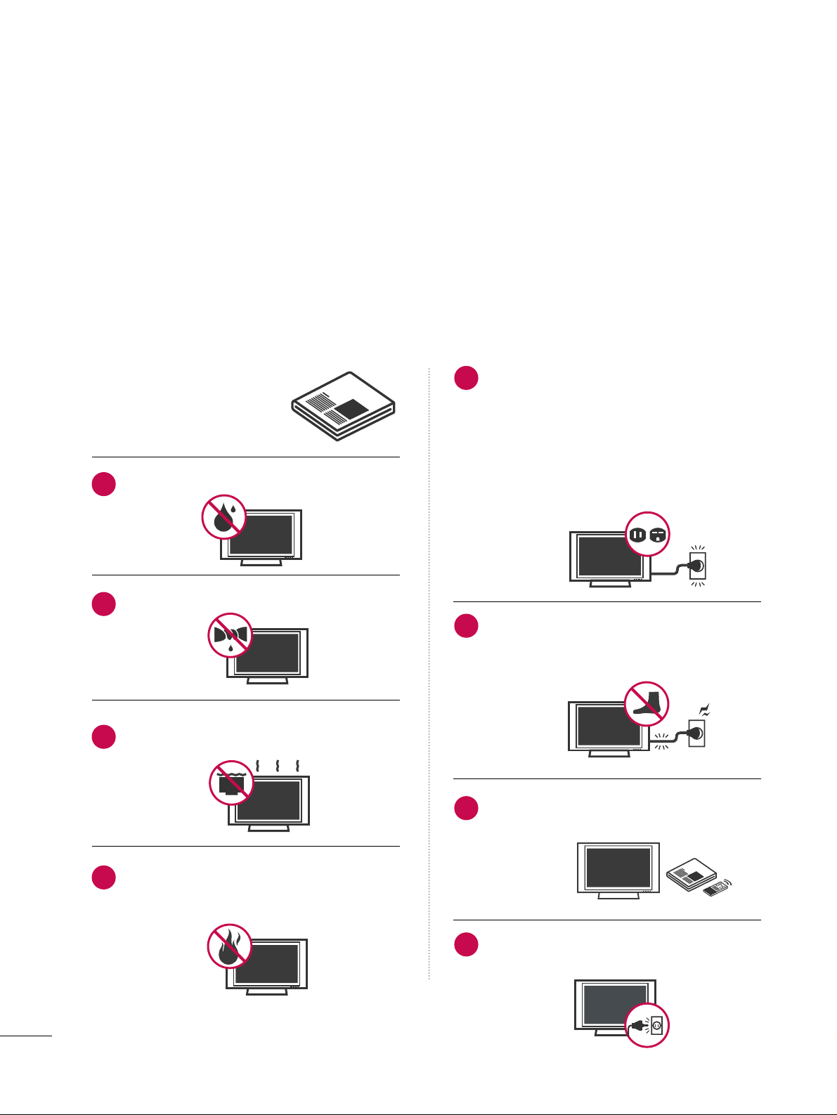
Do not use this apparatus near water.
Clean only with dry cloth.
Do not block any ventilation openings. Install in
accordance with the manufacturer’s instructions.
Do not install near any heat sources such as
radiators, heat registers, stoves, or other apparatus
(including amplifiers)that produce heat.
Do not defeat the safety purpose of the polarized
or grounding-type plug. A polarized plug has
two blades with one wider than the other. A
grounding type plug has two blades and a third
grounding prong, The wide blade or the third
prong are provided for your safety. If the provided
plug does not fit into your outlet, consult an
electrician for replacement of the obsolete outlet.
Protect the power cord from being walked on
or pinched particularly at plugs, convenience
receptacles, and the point where they exit from
the apparatus.
Only use attachments/accessories specified by
the manufacturer.
Unplug this apparatus when unused for long
periods of time.
1
2
3
4
5
6
7
8
Page 5
3
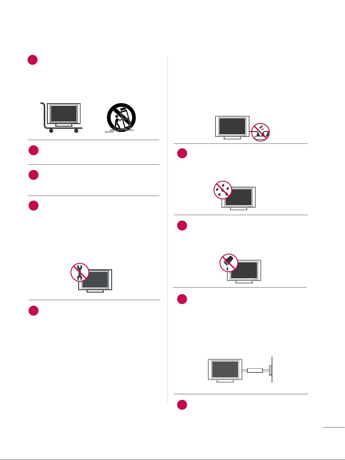
Use only with the cart, stand, tripod, bracket,
or table specified by the manufacturer, or sold
with the apparatus. When a cart is used, use
caution when moving the cart/apparatus
combination to avoid injury from tip-over.
Never touch this apparatus or antenna during
a thunder or lighting storm.
Do not allow a impact shock or any objects to
fall into the product, and do not drop onto the
screen with something.
Refer all servicing to qualified service personnel.
Servicing is required when the apparatus has
been damaged in any way, such as power-supply
cord or plug is damaged, liquid has been
spilled or objects have fallen into the apparatus,
the apparatus has exposed to rain or moisture,
does not operate normally, or has been
dropped.
CAUTION concerning the Power Cord :
Most appliances recommend they be placed
upon a dedicated circuit; that is, a single outlet
circuit which powers only that appliance and
has no additional outlets or branch circuits.
Check the specification page of this owner's
manual to be certain.
Do not overload wall outlets. Overloaded wall
outlets, loose or damaged wall outlets, extension
cords, frayed power cords, or damaged or
cracked wire insulation are dangerous. Any of
these conditions could result in electric shock
or fire. Periodically examine the cord of your
appliance, and if its appearance indicates damage or deterioration, unplug it, discontinue use
of the appliance, and have the cord replaced
with an exact replacement part by an authorized
servicer. Protect the power cord from physical
or mechanical abuse, such as being twisted,
kinked, pinched, closed in a door, or walked
upon. Pay particular attention to plugs, wall
outlets, and the point where the cord exits the
appliance.
Outdoor use marking :
WARNING - To reduce the risk of fire or elec-
tric shock, do not expose this appliance to rain
or moisture.
Wet Location Marking : Apparatus shall not be
exposed to dripping or splashing and no
objects filled with liquids, such as vases, shall
be placed on or over apparatus.
GGRROOUU NNDD IINNGG
Ensure that you connect the earth ground wire
to prevent possible electric shock. If grounding
methods are not possible, have a qualified
electrician install a separate circuit breaker.
Do not try to ground the unit by connecting it
to telephone wires, lightening rods, or gas pipes.
DDIISSCC OONNNNEECC TTIINN GG DDEEVVIICCEE FFRROOMM MMAAIINNSS
Mains plug is the disconnecting device. The
plug must remain readily operable.
9
12
10
11
13
14
15
16
17
Power
Supply
Short-circuit
Breaker
Page 6

4
CONTENTS
WARNING / CAUTION
. . . . . . . . . . . . . . . . . . . . . . . . . . . . 1
SAFETY INSTRUCTIONS
. . . . . . . . . . . . . . . . . . . . . . . . . . 2
FEATURE OF THIS TV
. . . . . . . . . . . . . . . . . . . . . . . . . . . . . . . 6
PREPARATION
Accessories
. . . . . . . . . . . . . . . . . . . . . . . . . . . . . . . . . . . . . . . . . . . . . . . . . . . . . . 7
Front Panel Information . . . . . . . . . . . . . . . . . . . . . . . . . . . . . . . . . . . . . 8
Back Panel Information
. . . . . . . . . . . . . . . . . . . . . . . . . . . . . . . . . . . .
10
Stand Installation
. . . . . . . . . . . . . . . . . . . . . . . . . . . . . . . . . . . . . . . . . . . .12
VESA Wall Mounting
. . . . . . . . . . . . . . . . . . . . . . . . . . . . . . . . . . . . . . . .
13
Desktop Pedestal Installation
. . . . . . . . . . . . . . . . . . . . . . . . . . . .13
Back Cover for Wire Arrangement
. . . . . . . . . . . . . . . . . . . . . 14
Attaching the TV to a Wall
. . . . . . . . . . . . . . . . . . . . . . . . . . . . . . . 16
Antenna or Cable Connection
. . . . . . . . . . . . . . . . . . . . . . . . . . 17
EXTERNAL EQUIPMENT SETUP
HD Receiver Setup
. . . . . . . . . . . . . . . . . . . . . . . . . . . . . . . . . . . . . . . . .
18
DVD Setup
. . . . . . . . . . . . . . . . . . . . . . . . . . . . . . . . . . . . . . . . . . . . . . . . . . . . . .
21
VCR Setup
. . . . . . . . . . . . . . . . . . . . . . . . . . . . . . . . . . . . . . . . . . . . . . . . . . . . . 23
Other A/V Source Setup . . . . . . . . . . . . . . . . . . . . . . . . . . . . . . . . .
25
PC Setup
. . . . . . . . . . . . . . . . . . . . . . . . . . . . . . . . . . . . . . . . . . . . . . . . . . . . . . . .26
Audio Out Setup . . . . . . . . . . . . . . . . . . . . . . . . . . . . . . . . . . . . . . . . . . . . .
31
WATCHING TV / CHANNEL CONTROL
Remote Control Functions
. . . . . . . . . . . . . . . . . . . . . . . . . . . . . . . 32
Turning On TV
. . . . . . . . . . . . . . . . . . . . . . . . . . . . . . . . . . . . . . . . . . . . . . . . 34
Channel Selection
. . . . . . . . . . . . . . . . . . . . . . . . . . . . . . . . . . . . . . . . . . . 34
Volume Adjustment
. . . . . . . . . . . . . . . . . . . . . . . . . . . . . . . . . . . . . . . . .
34
On-Screen Menus Selection
. . . . . . . . . . . . . . . . . . . . . . . . . . . . .
35
Channel Setup
- Auto Scan (Auto Tuning)
. . . . . . . . . . . . . . . . . . . . . . . . . . .
36
- Add / Delete Channel (Manual Tuning) . . . . . . 37
- Channel Editing
. . . . . . . . . . . . . . . . . . . . . . . . . . . . . . . . . . . . . . . . 38
Input List
. . . . . . . . . . . . . . . . . . . . . . . . . . . . . . . . . . . . . . . . . . . . . . . . . . . . . . . .
39
SimpLink
. . . . . . . . . . . . . . . . . . . . . . . . . . . . . . . . . . . . . . . . . . . . . . . . . . . . . . . . .
40
Input Label
. . . . . . . . . . . . . . . . . . . . . . . . . . . . . . . . . . . . . . . . . . . . . . . . . . . . .
42
Key Lock
. . . . . . . . . . . . . . . . . . . . . . . . . . . . . . . . . . . . . . . . . . . . . . . . . . . . . . . . . 43
PICTURE CONTROL
Picture Size (Aspect Ratio) Control . . . . . . . . . . . . . . . . . . 44
Preset Picture Settings
- Picture Mode - Preset
. . . . . . . . . . . . . . . . . . . . . . . . . . . . . . . 45
- Color Tone - Preset
. . . . . . . . . . . . . . . . . . . . . . . . . . . . . . . . . . .
46
Manual Picture Adjustment
- Picture Mode - User Mode
. . . . . . . . . . . . . . . . . . . . . . . . 47
- Color Tone - User Mode
. . . . . . . . . . . . . . . . . . . . . . . . . . .
48
XD - Picture Improvement Technology
. . . . . . . . . . . . .
49
Advanced - Cinema 3:2 Pulldown Mode
. . . . . . . . . . .50
Advanced - Black (Darkness) Level
. . . . . . . . . . . . . . . . . . . 51
Picture Reset
. . . . . . . . . . . . . . . . . . . . . . . . . . . . . . . . . . . . . . . . . . . . . . . . . 52
Image Sticking Minimization (ISM) Method
. . . . . . . 53
Low - Power Picture Mode
. . . . . . . . . . . . . . . . . . . . . . . . . . . . . . . 54
SOUND & LANGUAGE CONTROL
Auto Volume Leveller (Auto Volume)
. . . . . . . . . . . . . . . . .
55
Preset Sound Settings (Sound Mode)
. . . . . . . . . . . . . . 56
Sound Setting Adjustment - User Mode
. . . . . . . . . . .57
Balance
. . . . . . . . . . . . . . . . . . . . . . . . . . . . . . . . . . . . . . . . . . . . . . . . . . . . . . . . . . 58
TV Speakers On/Off Setup
. . . . . . . . . . . . . . . . . . . . . . . . . . . . . . 59
Stereo/SAP Broadcasts Setup
. . . . . . . . . . . . . . . . . . . . . . . . . . 60
Audio Language
. . . . . . . . . . . . . . . . . . . . . . . . . . . . . . . . . . . . . . . . . . . . . . 61
On-Screen Menus Language Selection
. . . . . . . . . . . . . .
62
Caption Mode
. . . . . . . . . . . . . . . . . . . . . . . . . . . . . . . . . . . . . . . . . . . . . . . .
63
- Analog Broadcasting System Captions
. . . . . . . 64
- Digital Broadcasting System Captions
. . . . . . . .
65
- Caption Option
. . . . . . . . . . . . . . . . . . . . . . . . . . . . . . . . . . . . . . .
66
Page 7

5
TIME SETTING
Clock Setting
- Auto Clock Setup
. . . . . . . . . . . . . . . . . . . . . . . . . . . . . . . . . . . . 67
- Manual Clock Setup . . . . . . . . . . . . . . . . . . . . . . . . . . . . . . . . .
68
Auto On/Off Timer Setting
. . . . . . . . . . . . . . . . . . . . . . . . . . . . . 69
Sleep Timer Setting
. . . . . . . . . . . . . . . . . . . . . . . . . . . . . . . . . . . . . . . . .
70
Auto Shut-off Setting
. . . . . . . . . . . . . . . . . . . . . . . . . . . . . . . . . . . . . . .71
PARENTAL CONTROL / RATINGS
Set Password & Lock System
. . . . . . . . . . . . . . . . . . . . . . . . . . .
72
Channel Blocking
. . . . . . . . . . . . . . . . . . . . . . . . . . . . . . . . . . . . . . . . . . . .
74
External Input Blocking . . . . . . . . . . . . . . . . . . . . . . . . . . . . . . . . . . . . 74
Movie & TV Rating
. . . . . . . . . . . . . . . . . . . . . . . . . . . . . . . . . . . . . . . . . . 75
APPENDIX
Troubleshooting
. . . . . . . . . . . . . . . . . . . . . . . . . . . . . . . . . . . . . . . . . . . . . . 78
Maintenance
. . . . . . . . . . . . . . . . . . . . . . . . . . . . . . . . . . . . . . . . . . . . . . . . . . . 80
Product Specifications
. . . . . . . . . . . . . . . . . . . . . . . . . . . . . . . . . . . . . 81
Programming the Remote Control
. . . . . . . . . . . . . . . . . . .
83
IR Codes
. . . . . . . . . . . . . . . . . . . . . . . . . . . . . . . . . . . . . . . . . . . . . . . . . . . . . . .
87
External Control Through RS-232C
. . . . . . . . . . . . . . . . . .
89
Open Source License
. . . . . . . . . . . . . . . . . . . . . . . . . . . . . . . . . . . . . . .
96
Page 8

6
FEATURE OF THIS TV
LG's own special digital image generator, consisting
of a full digital image processor, six different main
picture quality factors.
High-definition television. High-resolution digital
television broadcast and playback system composed
of roughly a million or more pixels, 16:9 aspect-ratio
screens, and AC3 digital audio. A subset of digital
television, HDTV formats include 1080i and 720p
resolutions.
With HDMI CEC support of LG’s audio/video device
connected to the HDMI (high-definition multimedia
interface), LG TV with this logo works easily with one
remote control.
Manufactured under license from Dolby Laboratories.
“
Dolby
“and the double-D symbol are trademarks of
Dolby Laboratories.
is a trademark of SRS Labs, Inc.
TruSurround XT technology is incorporated under
license from SRS Labs, Inc.
It has 2 HDMI ports that connect audio and video
devices with one cable and produces the highest
quality digital images and sound.
FOR LCD TV
■
If the TV feels cold to the touch, there may be a small “flicker” when it is turned on. This is normal, there is
nothing wrong with TV.
■
Some minute dot defects may be visible on the screen, appearing as tiny red, green, or blue spots. However,
they have no adverse effect on the monitor's performance.
■
Avoid touching the LCD screen or holding your finger(s) against it for long periods of time. Doing so may produce
some temporary distortion effects on the screen.
On Disposal
a. The fluorescent lamp used in this product contains a small amount of mercury.
b. Do not dispose of this product with general household waste.
c. Disposal of this product must be carried out in accordance to the regulations of your local authority.
Page 9
PREPARATION
7
PREPARATION
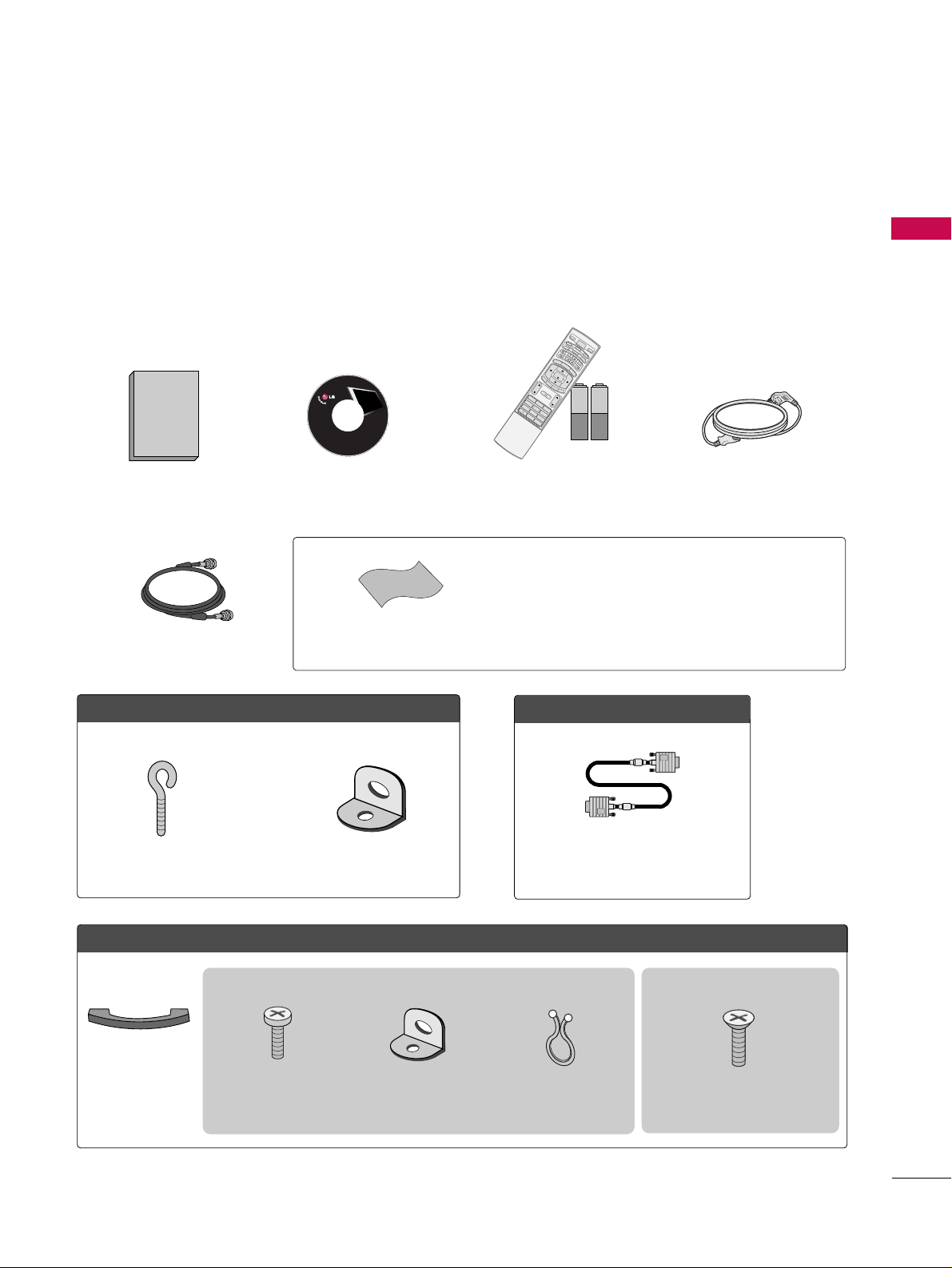
ACCESSORIES
Ensure that the following accessories are included with your product. If an accessory is missing, please contact
the dealer where you purchased the product.
User must use shielded signal interface cables (D-sub 15 pin cable) with ferrite cores to maintain standard
compliance for the product.
The accessories can be different from the figures shown here.
75ohm Round Cable
OOppttiioonn EExxttrraass
D-sub 15 pin Cable
FFoorr LLCCDD TTVV mmooddeellss
2-Eye-bolts
(Refer to p.16)
2-Wall brackets
(Refer to p.16)
FFoorr PPllaassmmaa TTVV mmooddeellss
Cable
Management
4-Bolts for stand assembly
(Refer to p.12)
3322// 3377 iinn cchh ee ss oonnll yy
* Slightly wipe stained spot on the exterior only with the polishing
cloth for the product exterior if there is stain or fingerprint on
surface of the exterior.
* Do not wipe roughly when removing stain. Please be cautions of
that excessive pressure may cause scratch or discoloration.
Polishing Cloth
1.5V 1.5V
Owner’s Manual CD Manual
123
456
78
0
9
B
A
C
K
V
O
L
C
H
M
U
T
E
FAV
B
R
I
G
H
T
-
MENU
BRIGHT +
E
N
T
E
R
E
X
I
T
TIM
ER
R
A
T
IO
S
I
M
P
L
I
N
K
P
O
W
E
R
V
C
R
T
V
DVD
A
U
D
I
O
C
A
B
L
E
S
T
B
MODE
T
V
I
N
P
U
T
INPUT
C
H
ENU
BRIGHT +
E
N
T
E
R
R
A
T
I
O
S
I
M
P
L
I
N
K
1
4
7
Remote Control,
Batteries
Power Cord
Copyright© 2007 LGE,
All Rights Reserved.
2- TV Bracket Bolts
(Refer to p.16)
2- TV Brackets,
2- Wall Brackets
(Refer to p.16)
Twist Holder
Arrange the wires with
the twist holder.
This feature is not available for all models
This feature is not available for all models
Page 10
PREPARATION
8
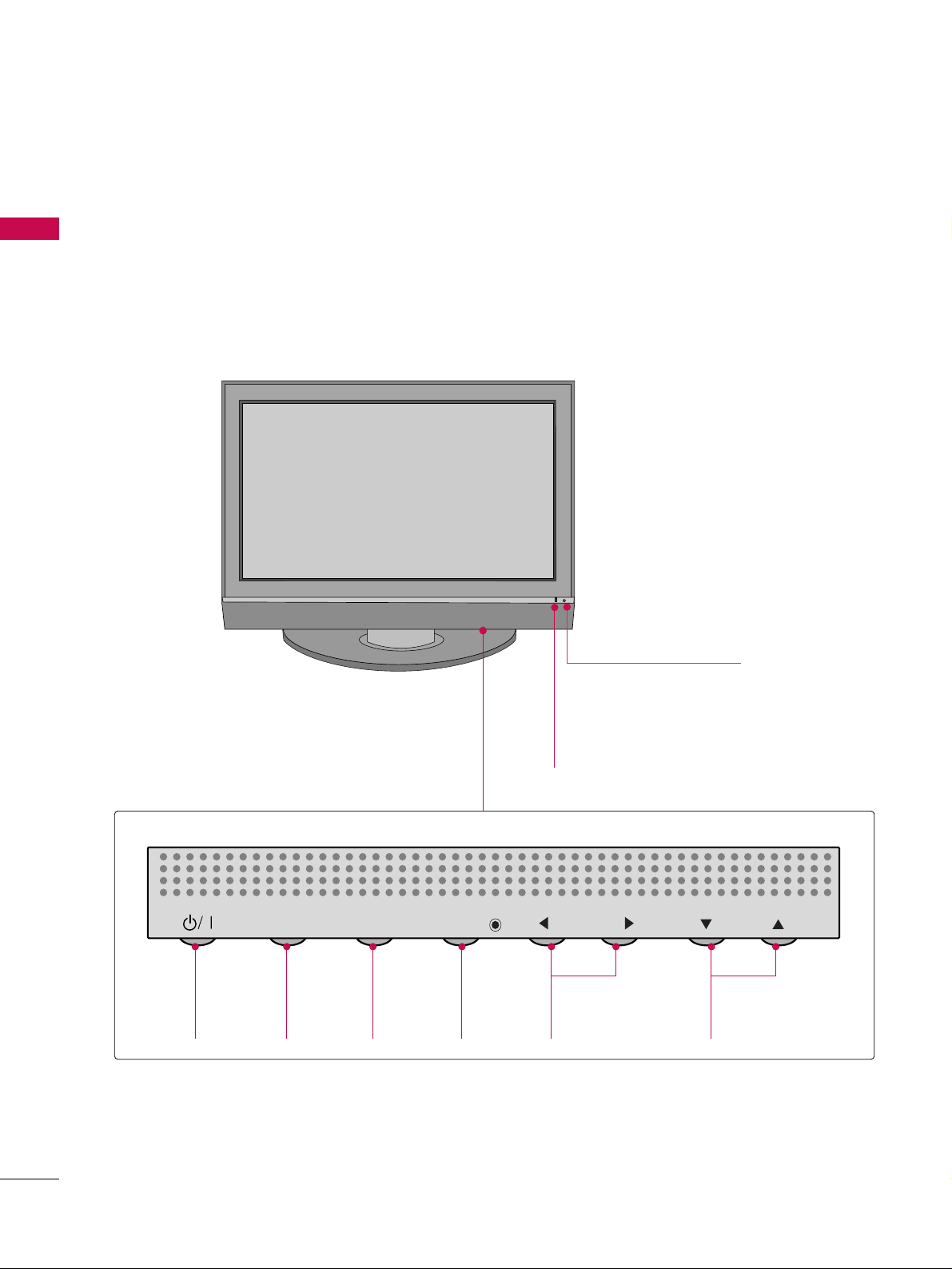
FRONT PANEL INFORMATION
PREPARATION
■
Here shown may be somewhat different from your TV.
■
NOTE: If your product has a protection tape attached, remove the tape.
And then wipe the product with a cloth (If a polishing cloth is included with your product, use it).
Plasma TV Model
POWER
Button
INPUT
Button
MENU
Button
ENTER
Button
VOLUME
(
FF,GG
)Buttons
CHANNEL
(
EE,DD
)Buttons
Power/Standby Indicator
Illuminates red in standby mode.
Illuminates green when the set is switched on.
Remote Control Sensor
INPUT
MENU
ENTER
VOL
CH
Page 11
PREPARATION
9
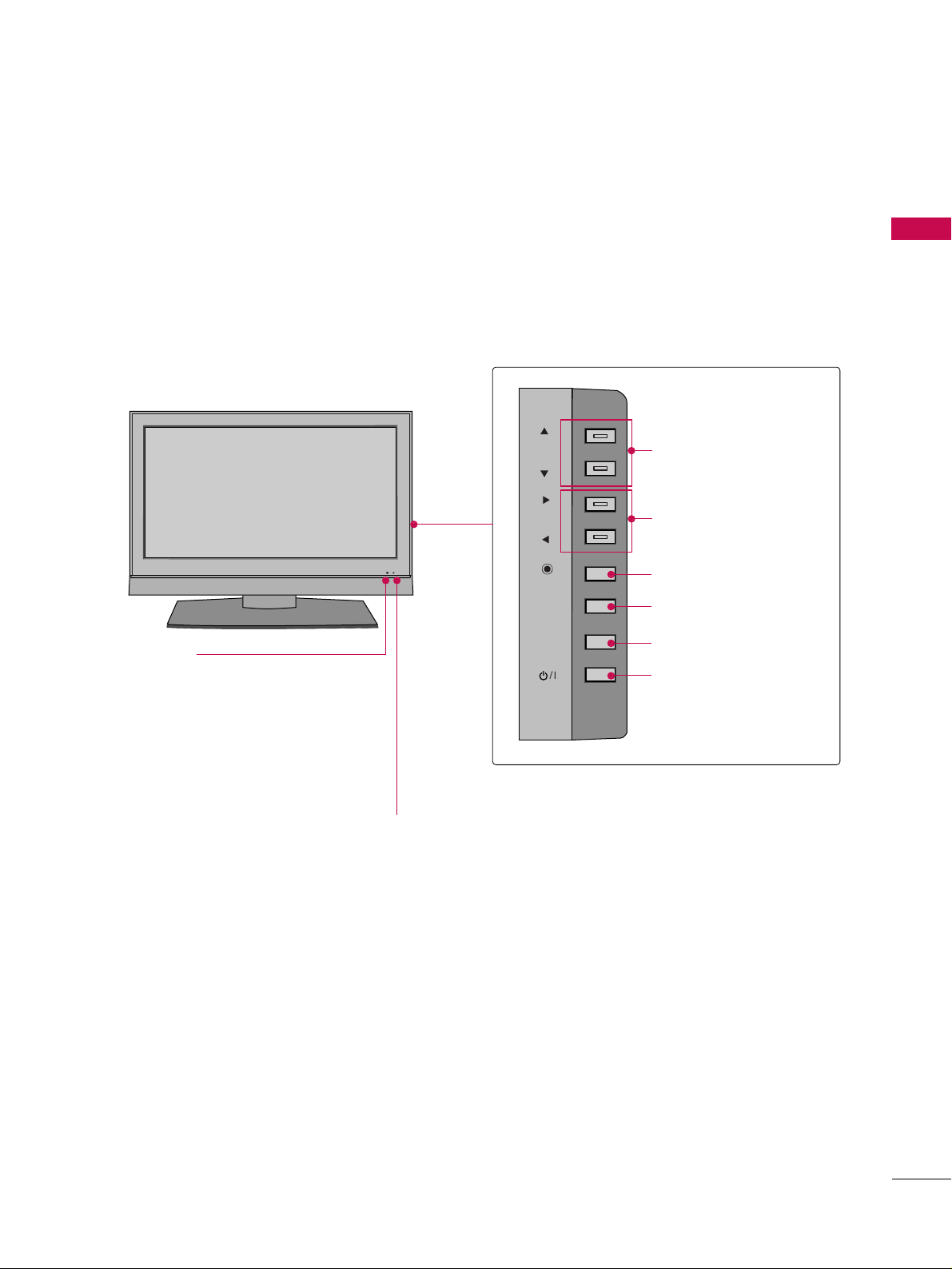
LCD TV Model
CHCH
VOLVOL
ENTERENTER
MENUMENU
INPUTINPUT
CH
VOL
ENTER
MENU
INPUT
Power/Standby Indicator
Illuminates red in standby mode.
Illuminates green when the set is
switched on.
Remote Control Sensor
CHANNEL (DD,EE)Buttons
VOLUME (FF,GG)Buttons
ENTER Button
MENU Button
INPUT Button
POWER Button
Page 12
PREPARATION
10
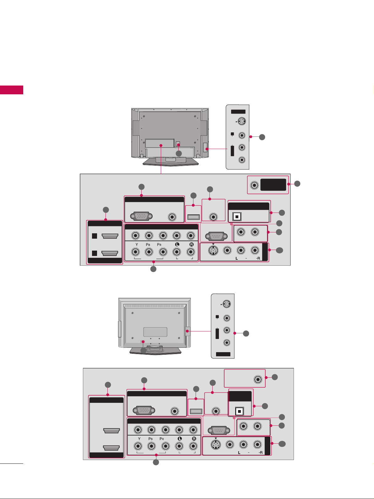
BACK PANEL INFORMATION
PREPARATION
Plasma TV Model
■
Here shown may be somewhat different from your TV.
LCD TV Model
R
RGB IN
COMPONENT IN
AUDIO
(RGB/DVI)
RGB(PC)
REMOTE
CONTROL IN
1
2
RS-232C IN
(CONTROL & SERVICE)
VIDEO
AUDIO
VIDEO
AUDIO OUT
MONO
( )
AUDIO
S-VIDEO
AV IN 1
SERVICE
ANTENNA/
CABLE IN
OPTICAL
DIGITAL AUDIO OUT
HDMI IN
HDMI/DVI IN
1
2
AV IN 2
L/MONO
R
AUDIO
VIDEO
S-VIDEO
10
11
AV IN 2
L/MONO
R
AUDIO
VIDEO
S-VIDEO
1
3
5
4
8
6
7
9
2
10
R
RGB IN
HDMI IN
HDMI/DVI IN
COMPONENT IN
AUDIO
(RGB/DVI)
RGB(PC)
REMOTE
CONTROL IN
ANTENNA/
CABLE IN
1
1
2
2
RS-232C IN
(CONTROL & SERVICE)
VIDEO
AUDIO
VIDEO
AUDIO OUT
OPTICAL
MONO
( )
AUDIO
S-VIDEO
DIGITAL
AUDIO OUT
AV IN 1
SERVICE
1
3
5
4
6
7
9
2
10
8
10
11
Page 13

PREPARATION
11
HDMI/DVI IN 1, HDMI IN 2
Connect a HDMI (DVI) connection to either input.
COMPONENT IN
Connect a component video/audio device to these
jacks.
RGB (PC)
Connect the output from a PC.
AUDIO (RGB/DVI)
Connect the audio from a PC or DTV.
SERVICE
Remote Control Port
Connect a wired remote control.
ANTENNA/CABLE IN
Connect over-the air signals to this jack.
Connect cable signals to this jack.
DIGITAL AUDIO OUT
Connect digital audio from various types of equipment.
Note: In standby mode, these ports do not work.
RS-232C IN (CONTROL & SERVICE) PORT
For external control devices.
AUDIO OUT
Connect analog audio to various types of equipment.
AV (Audio/Video) IN
Connect audio/video output from an external
device to these jacks.
S-VIDEO
Connect S-Video out from an S-VIDEO device.
Power Cord Socket
For operation with AC power.
Caution: Never attempt to operate the TV on DC
power.
1
11
2
3
4
5
6
8
7
9
10
Page 14
PREPARATION
12
PREPARATION
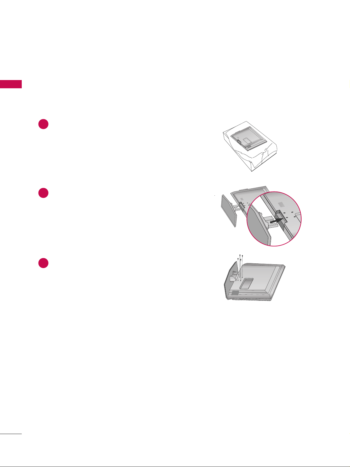
STAND INSTALLATION (Only 32/37 inches LCD TV models)
Carefully place the product screen side down on
a cushioned surface that will protect product and
screen from damage.
Assemble the product stand with the product as
shown.
Securely install the 4 bolts provided.
1
2
3
■
Here shown may be somewhat different from your TV.
Page 15
PREPARATION
13
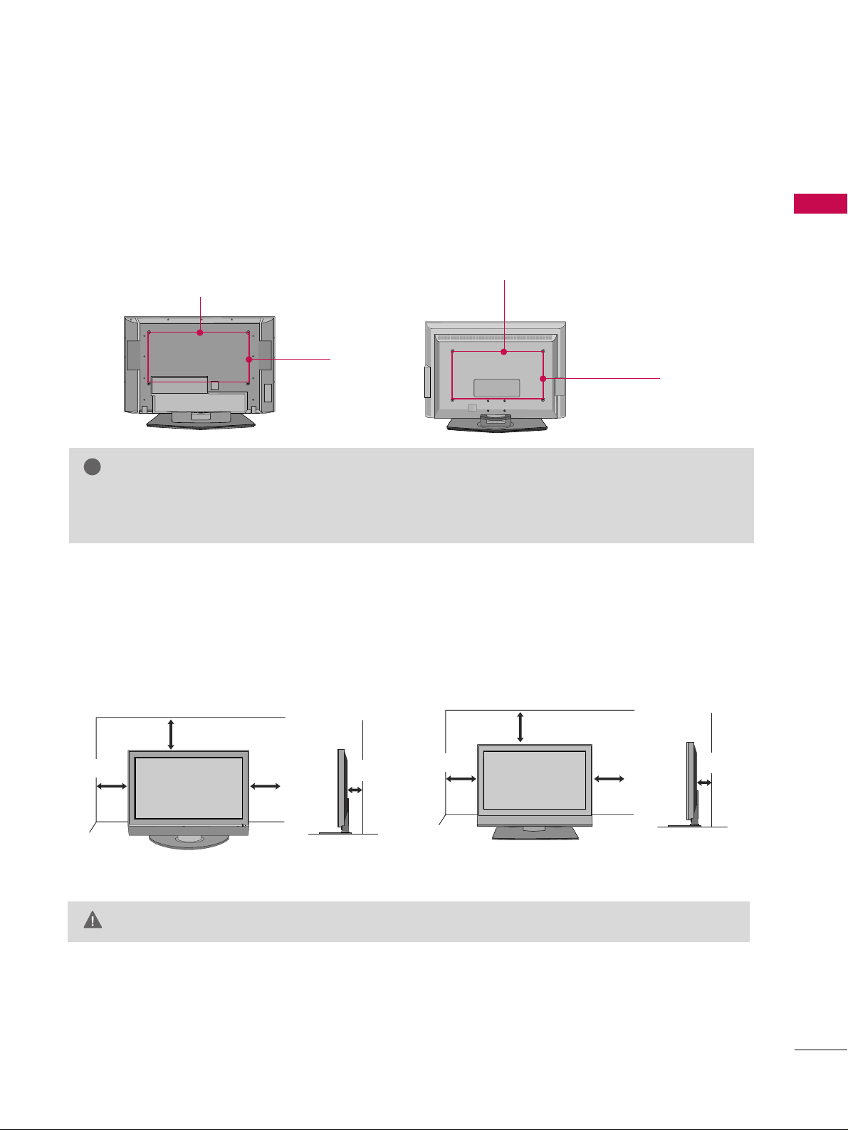
VESA WALL MOUNTING
This product accepts a VESA-compliant mounting interface pad. (optional)
There 4 threaded holes are available for attaching the bracket.
GG
Screw length needed depends on the wall mount used. For further information, refer to the VESA
Wall Mounting Instruction Guide.
NOTE
!
R
600 mm
400 mm
R
600 mm
(32 inches only: 200 mm)
400 mm
(32 inches only: 100 mm)
Plasma TV Model
LCD TV Model
For proper ventilation, allow a clearance of 4 inches on all four sides from the wall.
GG
Ensure adequate ventilation by following the clearance recommendations.
CAUTION
DESKTOP PEDESTAL INSTALLATION
4 inches
4 inches
4 inches
4 inches
4 inches
4 inches
4 inches
Plasma TV Model
LCD TV Model
4 inches
Page 16
PREPARATION
14
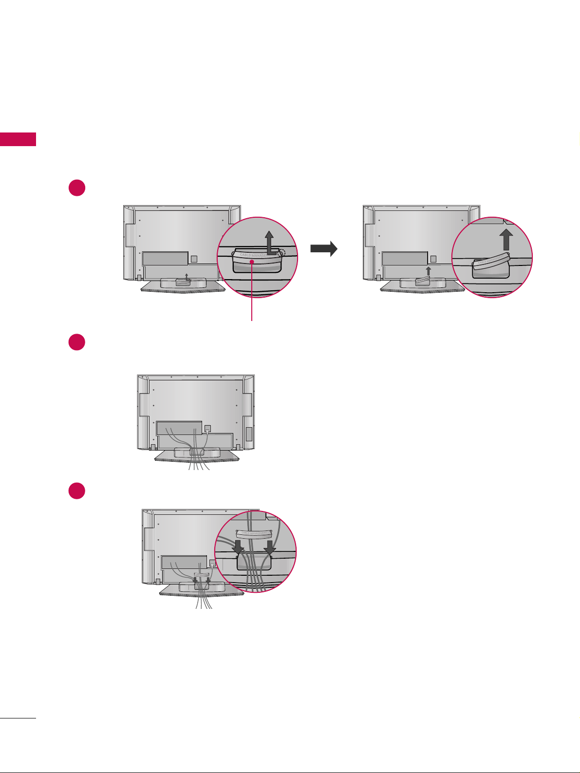
BACK COVER FOR WIRE ARRANGEMENT
PREPARATION
Hold the CABLE MANAGEMENT with both hands and pull it backward as shown.
Connect the cables as necessary.
To connect an additional equipment, see the EXTERNAL EQUIPMENT SETUP section.
1
2
Install the CABLE MANAGEMENT as shown.
3
■
Here shown may be somewhat different from your TV.
CABLE MANAGEMENT
Plasma TV Model
Page 17
PREPARATION
15
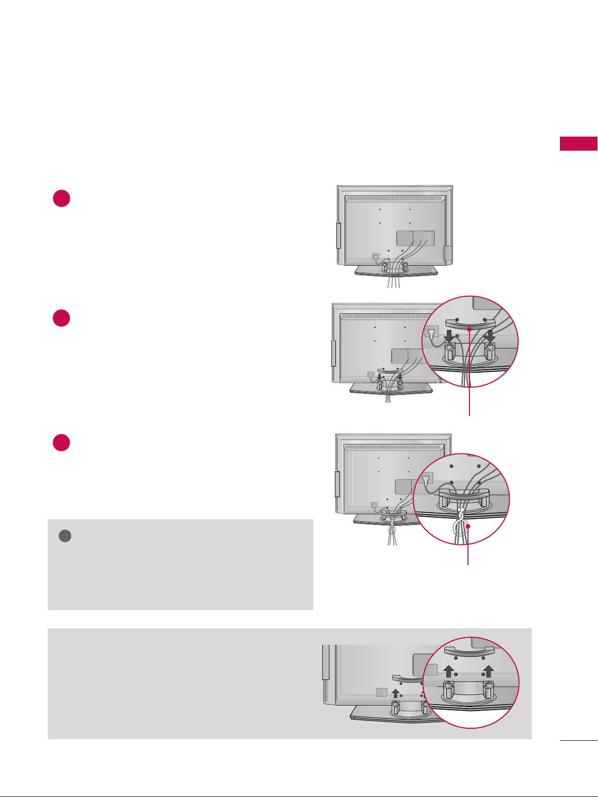
LCD TV Model
Connect the cables as necessary.
To connect an additional equipment, see the
EXTERNAL EQUIPMENT SETUP section.
Install the CABLE MANAGEMENT as shown.
How to remove the CABLE MANAGEMENT
GG
Hold the CABLE MANAGEMENT with both hands and
pull it backward.
CABLE MANAGEMENT
TWIST HOLDER
GG
Do not hold the CABLE MANAGEMENT when moving
the product.
- If the product is dropped, you may be injured or the
product may be broken.
NOTE
!
1
2
Bundle the cables using the supplied TWISTER HOLDER.
(This feature is not available for all models.)
3
Page 18
PREPARATION
16
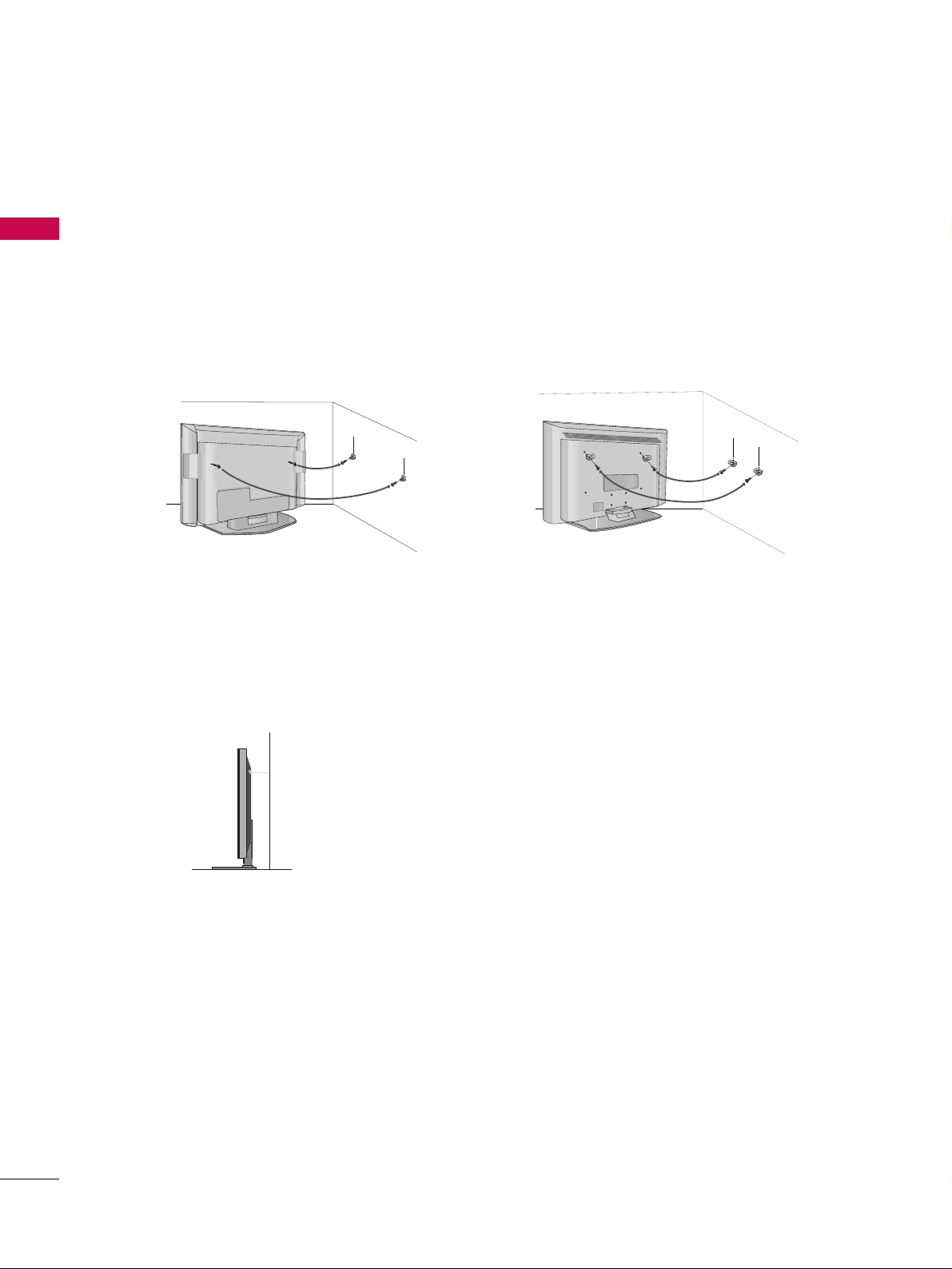
ATTACHING THE TV TO A WALL
PREPARATION
We recommend that you set up the TV close to a wall so it cannot fall over if pushed backwards.
Additionally, we recommend that the TV be attached to a wall so it cannot be pulled in a forward direction,
potentially causing injury or damaging the product.
Caution: Please make sure that children don’t climb on or hang from the TV.
Plasma TV Model
LCD TV Model
■
Insert the eye-bolts (or TV brackets and bolts) to tighten the product to the wall as shown in the picture.
*If your product has the bolts in the eye-bolts position before inserting the eye-bolts, loosen the bolts.
Secure the wall brackets with the bolts (not provided as parts of the product, must purchase separately) to
the wall. Match the height of the bracket that is mounted on the wall to the holes in the product.
Ensure the eye-bolts or brackets are tightened securely.
■
Use a sturdy rope (not provided as parts of the product, must purchase separately) to tie the product. It is safer to tie the rope so it
becomes horizontal between the wall and the product.
■
This feature is not available for all models.
■
Here shown may be somewhat different from your TV.
Page 19
PREPARATION
17
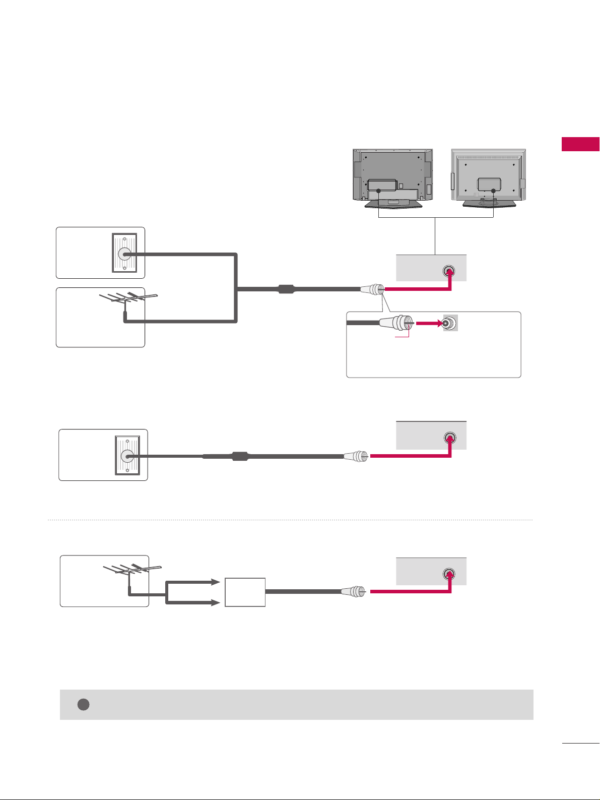
ANTENNA OR CABLE CONNECTION
1. Antenna (Analog or Digital)
Wall Antenna Socket or Outdoor Antenna without a Cable Box
Connections.
For optimum picture quality, adjust antenna direction if needed.
2. Cable
Wa ll
Antenna
Socket
Outdoor
Antenna
(VHF, UHF)
Cable TV
Wall Jack
Multi-family Dwellings/Apartments
(Connect to wall antenna socket)
RF Coaxial Wire (75 ohm)
RF Coaxial Wire (75 ohm)
Single-family Dwellings /Houses
(Connect to wall jack for outdoor antenna)
Be careful not to bend the bronze wire
when connecting the antenna.
Copper Wire
GG
The TV will let you know when the analog, cable, and digital channel scans are complete.
NOTE
!
■
To improve the picture quality in a poor signal area, please purchase a signal amplifier and install properly.
■
If the antenna needs to be split for two TV’s, install a 2-Way Signal Splitter.
■
If the antenna is not installed properly, contact your dealer for assistance.
Antenna
UHF
Signal
Amplifier
VHF
R
ANTENNA/
CABLE IN
R
ANTENNA/
CABLE IN
R
ANTENNA/
CABLE IN
■
Here shown may be somewhat different from your TV.
R
R
Page 20
EXTERNAL EQUIPMENT SETUP
18
EXTERNAL EQUIPMENT SETUP
HD RECEIVER SETUP
This TV can receive Digital Over-the-air/Cable signals without an external digital set-top box. However, if you do
receive digital signals from a digital set-top box or other digital external device, refer to the figure as shown below.
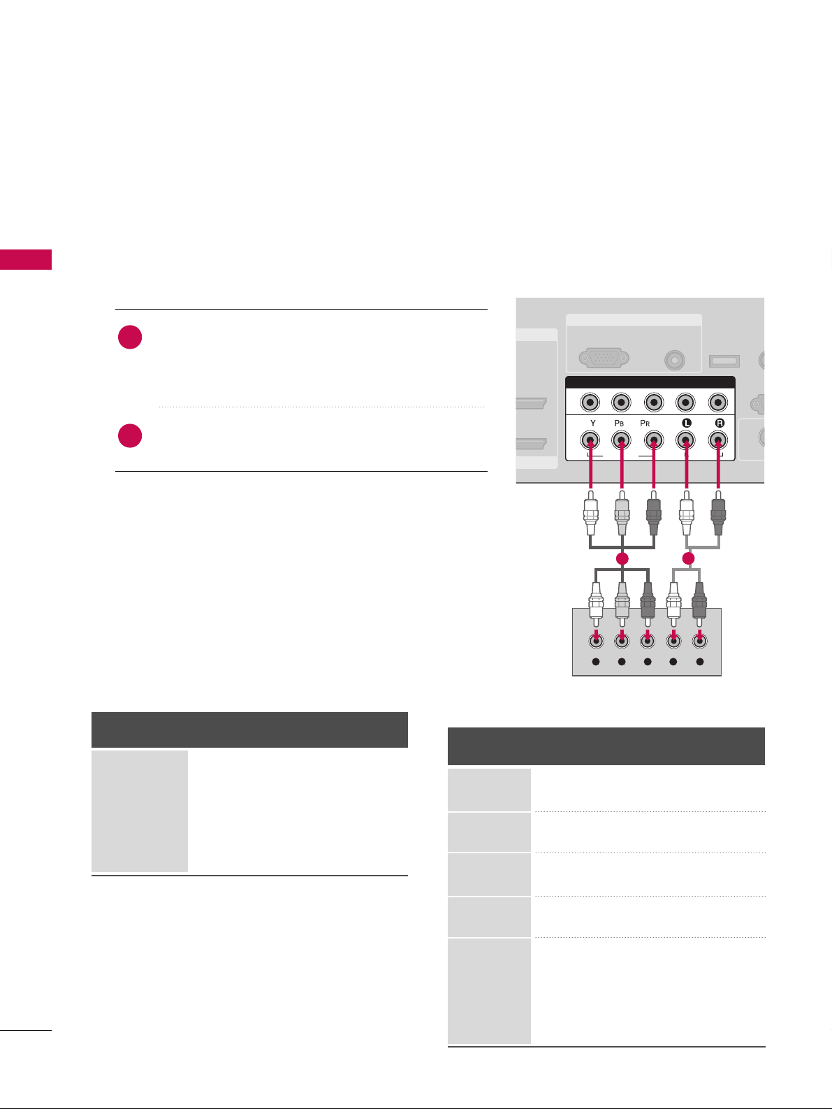
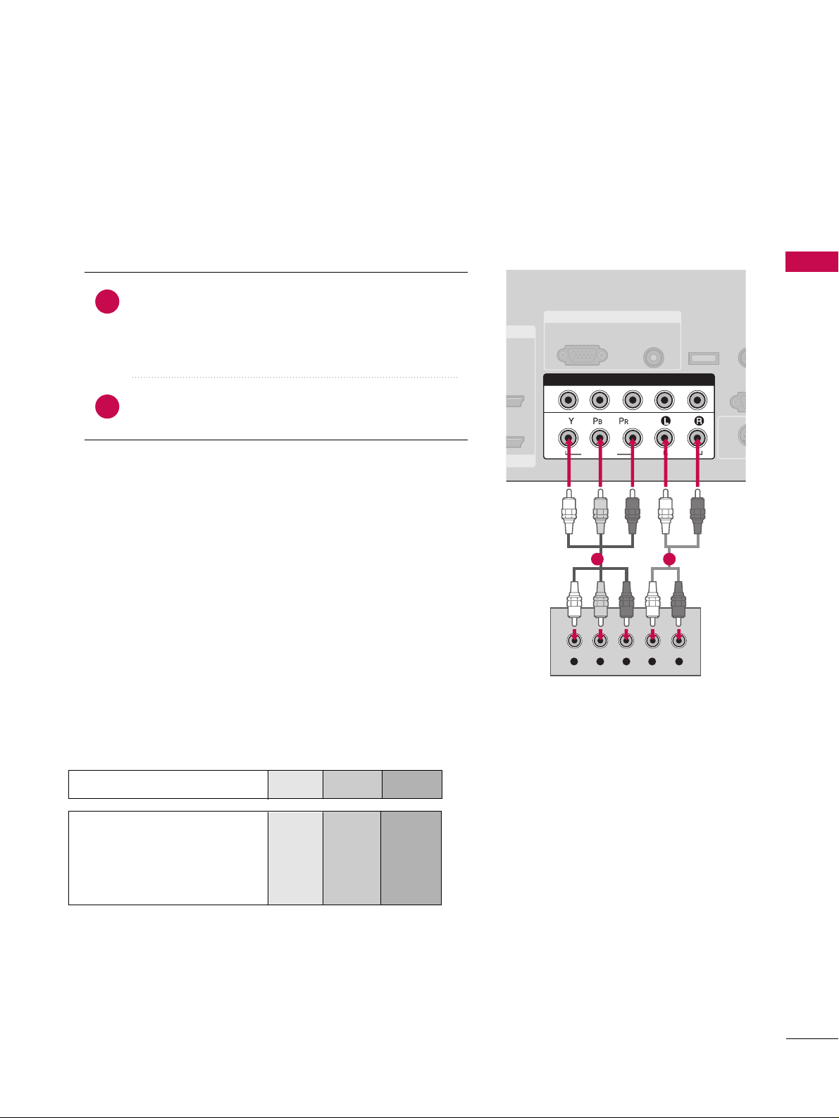
When connecting Component cable
1. How to connect
Connect the video outputs (Y, P
B, P
R
)
of the digital set
top box to the
CCOOMMPPOONN EENNTT IINN VV IIDDEEOO 11
jacks on
the set. Match the jack colors (Y = green, P
B = blue, and
P
R = red).
Connect the audio output of the digital set-top box to
the
CCOOMMPPOONN EENNTT IINN AAUU DDIIOO 11
jacks on the set.
2
1
2. How to use
■
Turn on the digital set-top box.
(
Refer to the owner’s manual for the digital set-top box. operation
)
■
Select
CC oommpp oo nneenntt 11
input source by using the
IINNPPUU TT
button on the remote control.
■
If connected to
CCOOMMPPOONNEE NN TT IINN22
input, select
CCoommpp oo nneenntt 22
input source.
■
To prevent the equipment damage, never plug in any power cords until you have finished connecting all equipment.
■
This part of EXTERNAL EQUIPMENT SETUP mainly use picture for LCD TV model.
RGB IN
/DVI IN
AUDIO
(RGB/DVI)
RGB(PC)
REM
CONT
RS
(CONTR
( )
S-V
COMPONENT IN
1
2
VIDEO
AUDIO
Y L RPB PR
SERVICE
1
2
Y, C
B/P
B, C
R/
PR
Horizontal Vertical
Frequency(KHz)Frequency(Hz
)
15.73 59.94
15.73 60.00
31.47 59.94
31.50 60.00
44.96 59.94
45.00 60.00
33.72 59.94
33.75 60.00
26.97 23.976
27.00 24.00
33.71 29.97
33.75 30.00
67.432 59.94
67.50 60.00
Resolution
720x480i
720x480p
1280x720p
1920x1080i
1920x1080p
Signal
480i
480p
720p
10 8 0 i
10 8 0 p
Component 1/2
Yes
Yes
Yes
Yes
Yes
HDMI1/2
No
Yes
Yes
Yes
Yes
Page 21
EXTERNAL EQUIPMENT SETUP
19
RGB IN
COMPONENT IN
AUDIO
(RGB/D
RGB(PC)
1
2
VIDEO
( )
HDMI IN
HDMI/DVI IN
1
2
HDMI-DTV OUTPUT
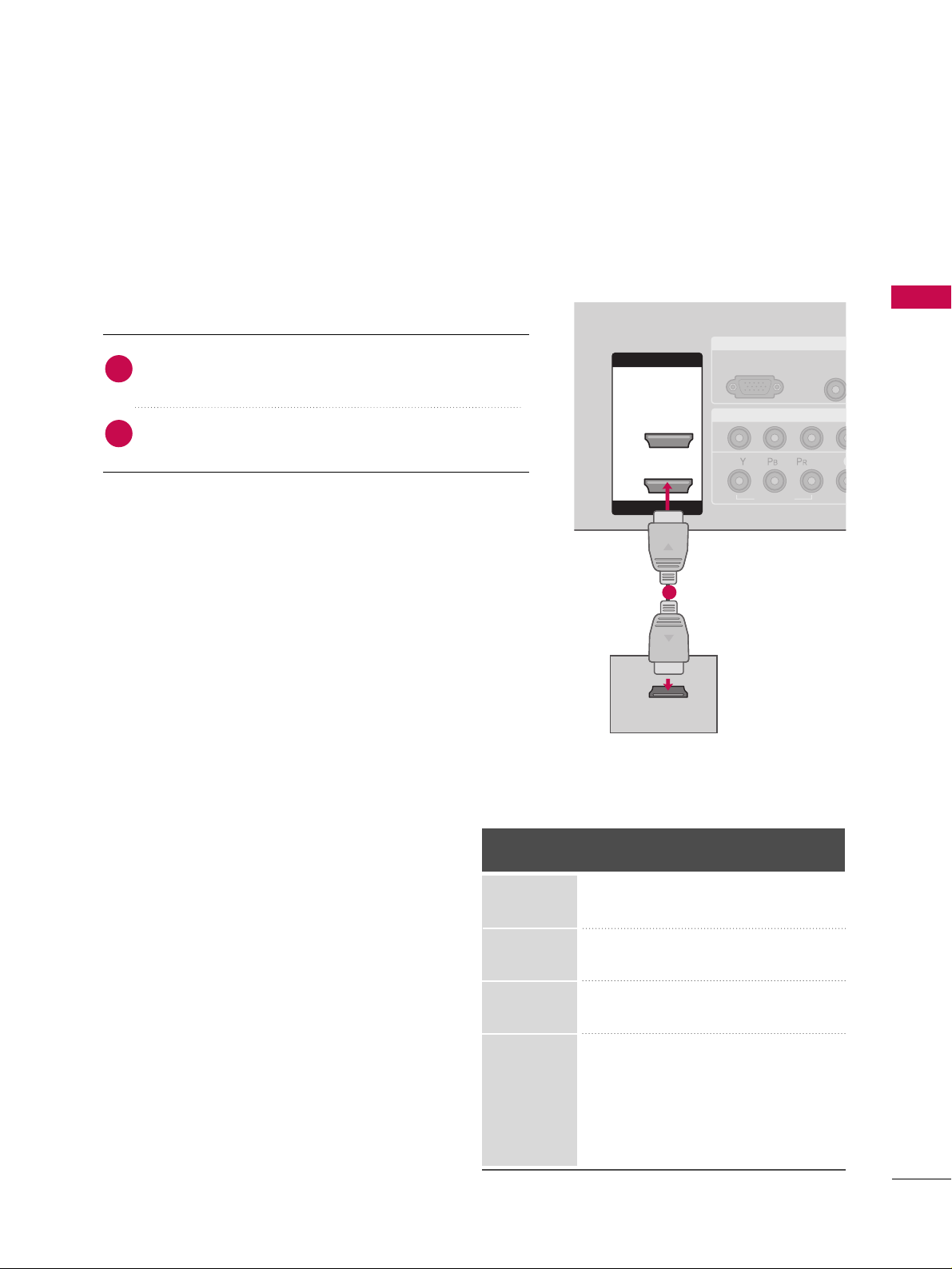
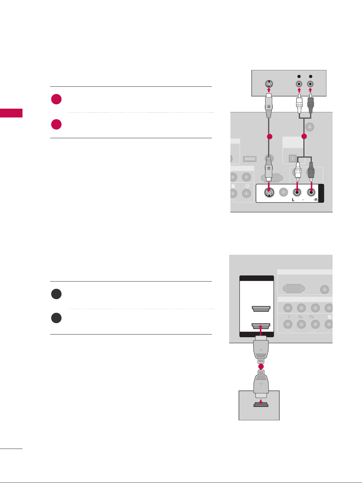
When connecting HDMI cable
Connect the digital set-top box to
HHDDMMII //DDVVII II NN 11
or
HHDDMMII IINN 22
jack on the set.
No separated audio connection is necessary.
HDMI supports both audio and video.
1. How to connect
2. How to use
■
Turn on the digital set-top box.
(
Refer to the owner’s manual for the digital set-top box.
)
■
Select
HHDD MM II11
or
HHDD MM II22
input source by using the
IINNPPUU TT
button on the remote control.
2
1
1
HDMI1/DVI-DTV, HDMI2-DTV mode
Horizontal Vertical
Frequency(KHz)Frequency(Hz
)
31.47 59.94
31.50 60.00
44.96 59.94
45.00 60.00
33.72 59.94
33.75 60.00
26.97 23.976
27.00 24.00
33.71 29.97
33.75 30.00
67.432 59.939
67.50 60.00
Resolution
720x480p
1280x720p
1920x1080i
1920x1080p
Page 22
EXTERNAL EQUIPMENT SETUP
20
EXTERNAL EQUIPMENT SETUP
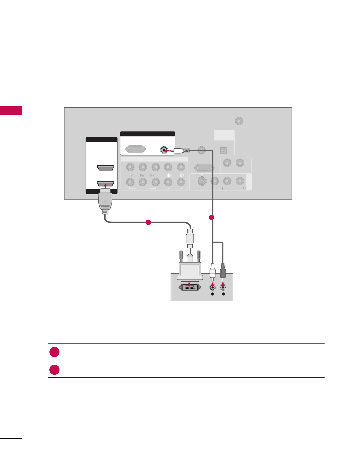
When connecting HDMI to DVI cable
( )
COMPONENT IN
AV IN 1
ANTENNA/
CABLE IN
1
2
RS-232C IN
(CONTROL & SERVICE)
VIDEO
AUDIO
AUDIO OUT
VIDEO
MONO
( )
AUDIO
S-VIDEO
HDMI IN
HDMI/DVI IN
1
2
RGB IN
AUDIO
(RGB/DVI)
L R
DVI-DTV OUTPUT
RGB(PC)
REMOTE
CONTROL IN
SERVICE
DIGITAL
AUDIO OUT
OPTICAL
Connect the DVI output of the digital set-top box to the
HHDDMMII//DD VVII IINN 11
jack on the set.
Connect the audio output of the digital set-top box to the
AAUUDDIIOO ((RR GGBB //DDVVII
))
jack on the set.
1. How to connect
■
Turn on the digital set-top box. (Refer to the owner’s manual for the digital set-top box.
)
■
Select
HHDD MM II11
input source by using the
IINNPPUU TT
button on the remote control.
2. How to use
2
1
1
2
Page 23
EXTERNAL EQUIPMENT SETUP
21
DVD SETUP
When connecting Component cable
Component Input ports
To get better picture quality, connect a DVD player to the component input ports as shown below.
Component ports on the TV
YPBP
R
Video output ports
on DVD player
Y
Y
Y
Y
P
B
B-Y
Cb
Pb
P
R
R-Y
Cr
Pr
Connect the video outputs (Y, P
B, P
R
)
of the DVD to the
CCOOMMPPOONN EENNTT IINN VVIIDDEE OO11
jacks on the set.
Match the jack colors
(
Y = green, P
B = blue, and P
R = red
)
.
Connect the audio outputs of the DVD to the
CCOOMMPPOONN EENNTT IINN AAUU DDIIOO 11
jacks on the set.
1. How to connect
2. How to use
■
Turn on the DVD player, insert a DVD.
■
Select
CC oommpp oo nneenntt 11
input source by using the
IINNPPUU TT
button on the remote control.
■
If connected to
CCOOMMPPOONNEE NN TT IINN 22
input, select
CCoommpp oo nneenntt 22
input source.
■
Refer to the DVD player's manual for operating instructions.
2
1
RGB IN
AUDIO
(RGB/DVI)
RGB(PC)
REM
CONT
RS
(CONTR
( )
S-VI
COMPONENT IN
1
2
VIDEO
AUDIO
Y L RPB PR
SERVICE
1 2
Page 24
EXTERNAL EQUIPMENT SETUP
22
EXTERNAL EQUIPMENT SETUP
When connecting with an S-Video cable
Connect the S-VIDEO output of the DVD to the
SS --VVIIDDEEOO
input on the set.
Connect the audio outputs of the DVD to the
AAUUDD IIOO
input jacks on the set.
1. How to connect
2. How to use
■
Turn on the DVD player, insert a DVD.
■
Select
AA VV11
input source by using the
IINNPPUU TT
button on the
remote control.
■
If connected to
AAVV IINN 22
, select
AA VV22
input source.
■
Refer to the DVD player's manual for operating instructions.
When connecting HDMI cable
Connect the HDMI output of the DVD to the
HHDDMMII //DDVVII IINN 11
or
HHDDMMII IINN 22
jack on the set.
No separated audio connection is necessary.
HDMI supports both audio and video.
1. How to connect
2. How to use
■
Select
HHDD MM II11
or
HHDD MM II22
input source by using the
IINNPPUU TT
button on the remote control.
■
Refer to the DVD player's manual for operating instructions.
2
1
2
1
(
)
N
IO
ANTENNA/
CABLE IN
RS-232C IN
(CONTROL & SERVICE)
AUDIO
AUDIO OUT
MONO
( )
AUDIO
S-VIDEO
AV IN 1
VIDEO
REMOTE
CONTROL IN
SERVICE
DIGITAL
AUDIO OUT
OPTICAL
L R
S-VIDEO
AUDIO
1
2
RGB IN
COMPONENT IN
AUDIO
(RGB/DVI
RGB(PC)
1
2
VIDEO
A
( )
HDMI IN
HDMI/DVI IN
1
2
HDMI-DVD OUTPUT
1
Page 25
EXTERNAL EQUIPMENT SETUP
23
VCR SETUP
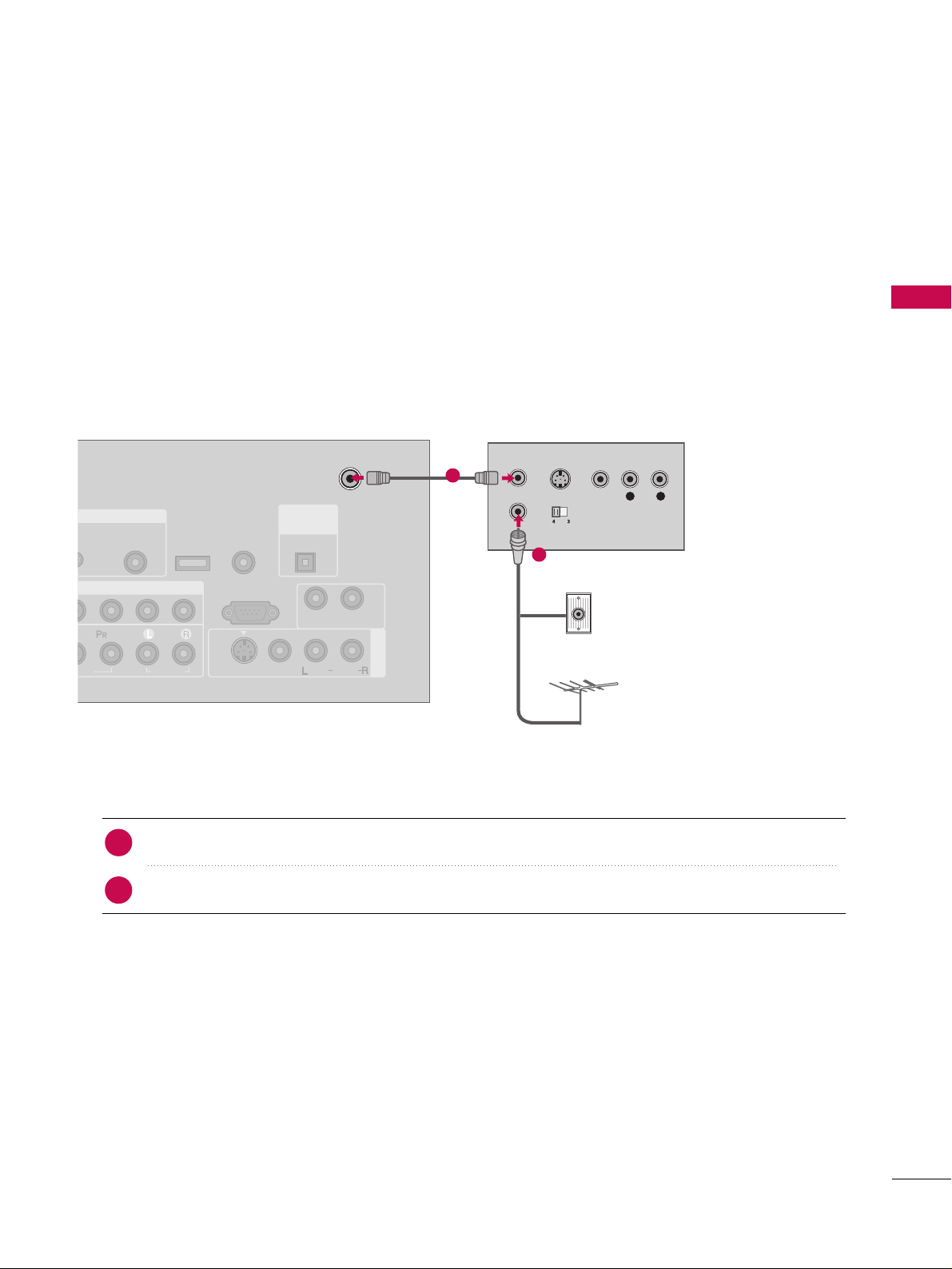
When connecting with an antenna
■
To avoid picture noise (interference), leave an adequate distance between the VCR and TV.
■
Use the ISM feature in the Option menu to avoid having a fixed image remain on the screen for a long period of time (Only Plasma TV model). If the 4:3 picture format is used; the fixed images on the sides of the
screen may remain visible on the screen. This phenomenon is common to all manufactures and in consequence the manufactures warranty does not cover the product bearing this phenomenon.
Connect the RF antenna out socket of the VCR to the
AANNTTEENNNNAA//CCAABBLL EE IINN
socket on the set.
Connect the antenna cable to the RF antenna in socket of the VCR.
1. How to connect
■
Set VCR output switch to 3 or 4 and then tune TV to the same channel number.
■
Insert a video tape into the VCR and press PLAY on the VCR. (Refer to the VCR owner’s manual.
)
2. How to use
2
1
L R
S-VIDEO VIDEO
OUTPUT
SWITCH
ANT IN
ANT OUT
GB IN
MPONENT IN
AV IN 1
AUDIO
(RGB/DVI)
ANTENNA/
CABLE IN
RS-232C IN
(CONTROL & SERVICE)
EO
AUDIO
AUDIO OUT
VIDEO
MONO
( )
AUDIO
S-VIDEO
( )
REMOTE
CONTROL IN
SERVICE
DIGITAL
AUDIO OUT
OPTICAL
Wall Jack
Antenna
1
2
Page 26
EXTERNAL EQUIPMENT SETUP
24
EXTERNAL EQUIPMENT SETUP
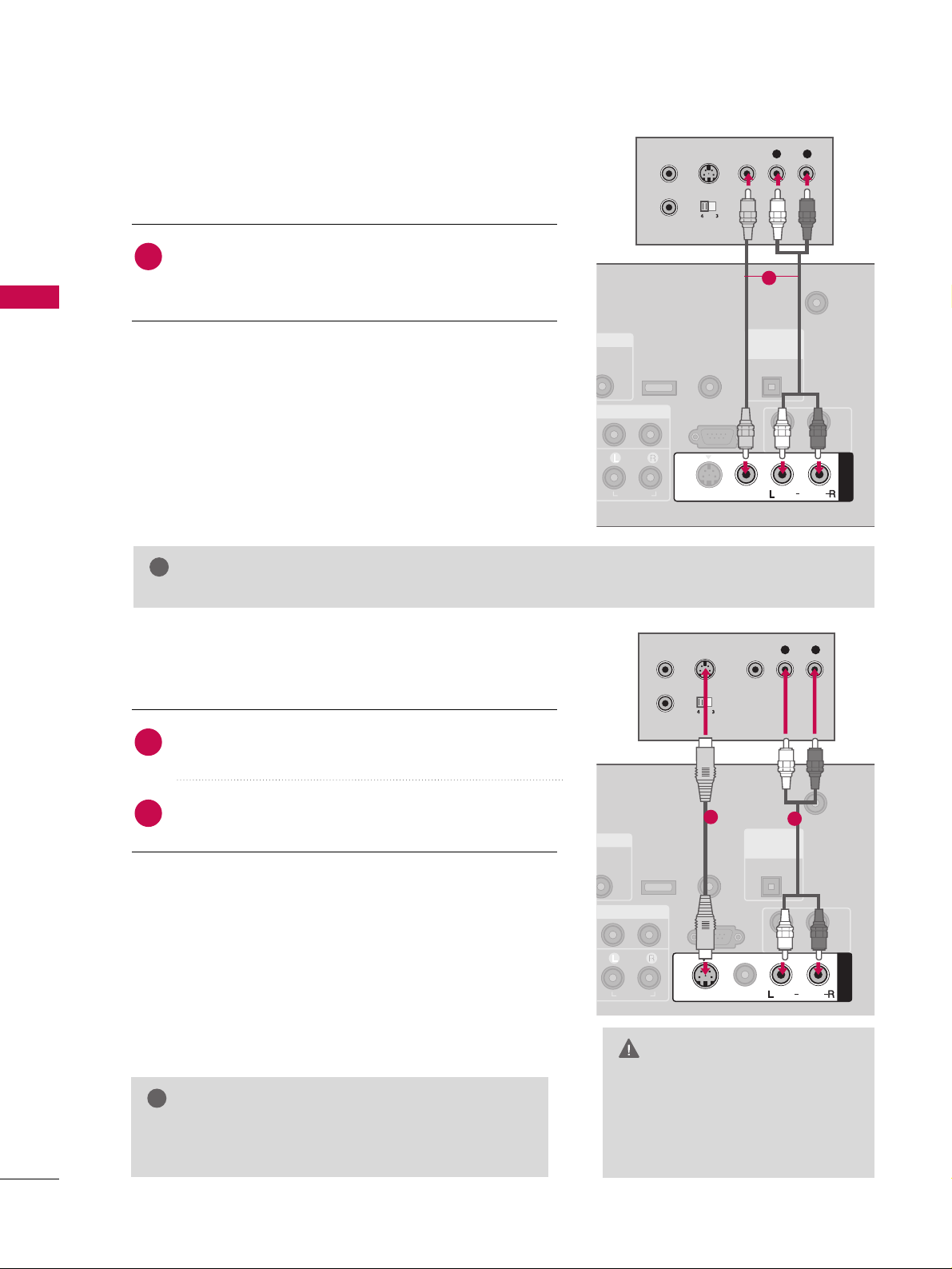
GG
Do not connect to both Video
and S-Video at the same time. In
the event that you connect both
Video and the S-Video cables,
only the S-Video will work.
CAUTION
When connecting with a RCA cable
GG
The picture quality is improved: compared to normal
composite (RCA cable) input.
NOTE
!
Connect the
AAUUDD IIOO/VV IIDDEEOO
jacks between TV and
VCR. Match the jack colors (Video = yellow, Audio Left
= white, and Audio Right = red)
1. How to connect
2. How to use
■
Insert a video tape into the VCR and press PLAY on the
VCR. (Refer to the VCR owner’s manual.
)
■
Select
AA VV11
input source by using the
IINNPPUU TT
button on
the remote control.
■
If connected to
AAVV IINN 22
, select
AA VV22
input source.
When connecting with an S-Video cable
Connect the S-VIDEO output of the VCR to the
SS --VVIIDDEEOO
input on the set.
Connect the audio outputs of the VCR to the
AAUUDD IIOO
input jacks on the set.
1. How to connect
2. How to use
■
Insert a video tape into the VCR and press PLAY on the VCR.
(
Refer to the VCR owner’s manual.
)
■
Select
AA VV11
input source by using the
IINNPPUU TT
button on the
remote control.
■
If connected to
AAVV IINN 22
, select
AA VV22
input source.
1
2
1
GG
If you have a mono VCR, connect the audio cable from the VCR to the
AAUUDD IIOO
LL//MMOONNOO
jack of the set.
NOTE
!
B/DVI)
ANTENNA/
CABLE IN
RS-232C IN
(CONTROL & SERVICE)
AUDIO
AUDIO OUT
AV IN 1
VIDEO
MONO
( )
AUDIO
S-VIDEO
REMOTE
CONTROL IN
SERVICE
DIGITAL
AUDIO OUT
OPTICAL
L R
S-VIDEO VIDEO
OUTPUT
SWITCH
ANT IN
ANT OUT
1
( )
(
)
B/DVI)
ANTENNA/
CABLE IN
RS-232C IN
(CONTROL & SERVICE)
AUDIO
AUDIO OUT
AV IN 1
VIDEO
MONO
( )
AUDIO
S-VIDEO
REMOTE
CONTROL IN
SERVICE
DIGITAL
AUDIO OUT
OPTICAL
L R
S-VIDEO VIDEO
OUTPUT
SWITCH
ANT IN
ANT OUT
1
2
Page 27
EXTERNAL EQUIPMENT SETUP
25
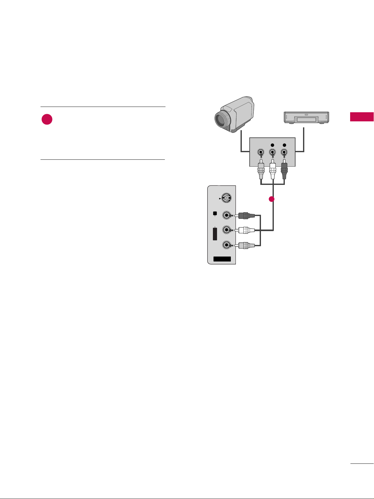
OTHER A/V SOURCE SETUP
AV IN 2
L/MONO
R
AUDIO
VIDEO
S-VIDEO
L R
VIDEO
Camcorder
Video Game Set
Connect the
AAUUDDIIOO/VVIIDDEEOO
jacks
between TV and external equipment.
Match the jack colors
.
(
Video = yellow, Audio Left = white, and
Audio Right = red
)
1. How to connect
2. How to use
■
Select
AA VV22
input source by using the
IINNPPUU TT
button on the remote control.
■
If connected to
AAVV IINN 11
input, select
AA VV11
input source.
■
Operate the corresponding external equipment.
1
1
Page 28

EXTERNAL EQUIPMENT SETUP
26
PC SETUP
EXTERNAL EQUIPMENT SETUP
This TV provides Plug and Play capability, meaning that the PC adjusts automatically to the TV's settings.
When connecting D-sub 15 pin cable
Connect the RGB output of the PC to the
RR GGBB
((
PP CC
))
jack on the set.
Connect the PC audio output to the
AAUUDDIIOO
((
RRGGBB//DDVVII
))
jack on the set.
1. How to connect
2. How to use
■
Turn on the PC and the TV.
■
Select
RR GGBB --PPCC
input source by using the
IINNPPUU TT
button
on the remote control.
2
1
COMPONENT IN
1
2
(CO
VIDEO
AUDIO
( )
RGB IN
AUDIO
(RGB/DVI)
RGB(PC)
RGB OUTPUT AUDIO
CO
SERVICE
I/DVI IN
1
2
Page 29
EXTERNAL EQUIPMENT SETUP
27
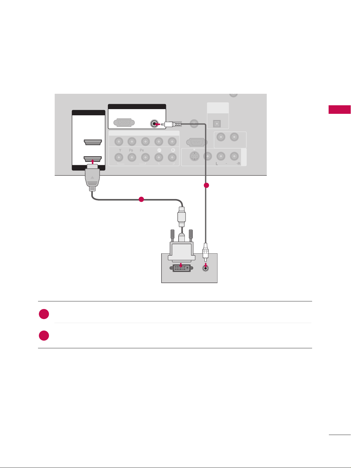
When connecting HDMI to DVI cable
Connect the DVI output of the PC to the
HHDDMMII //DDVVII II NN 11
jack on the set.
Connect the PC audio output to the
AAUUDDIIOO ((RRGGBB//DDVVII
))
jack on the set.
1. How to connect
2. How to use
■
Turn on the PC and the TV.
■
Select
HHDDMMII11
input source by using the
IINNPPUU TT
button on the remote control.
2
1
COMPONENT IN
AV IN 1
CABLE IN
1
2
RS-232C IN
(CONTROL & SERVICE)
VIDEO
AUDIO
AUDIO OUT
VIDEO
MONO
( )
AUDIO
S-VIDEO
HDMI IN
HDMI/DVI IN
1
2
RGB IN
AUDIO
(RGB/DVI)
DVI-PC OUTPUT
RGB(PC)
( )
AUDIO
REMOTE
CONTROL IN
SERVICE
DIGITAL
AUDIO OUT
OPTICAL
1
2
Page 30
EXTERNAL EQUIPMENT SETUP
28
EXTERNAL EQUIPMENT SETUP
GG
For LCD TV: To get the the best picture quality,
adjust the PC graphics card to 1366x768.
GG
For Plasma TV TV: To get the the best picture quality,
adjust the PC graphics card to 1360x768.
GG
Depending on the graphics card, DOS mode may
not work if a HDMI to DVI Cable is in use.
GG
Check the image on your TV. There may be noise
associated with the resolution, vertical pattern,
contrast or brightness in PC mode. If noise is
present, change the PC output to another resolution, change the refresh rate to another rate or
adjust the brightness and contrast on the VIDEO
menu until the picture is clear. If the refresh rate of
the PC graphic card can not be changed, change
the PC graphic card or consult the manufacturer of
the PC graphic card.
GG
Avoid keeping a fixed image on the screen for a
long period of time. The fixed image may become
permanently imprinted on the screen.
GG
The synchronization input form for Horizontal and
Vertical frequencies is separate.
NOTES
!
Supported Display Specifications
Horizontal Vertical
Frequency(KHz)Frequency(Hz
)
31.469 70.08
31.469 70.08
31.469 59.94
37.879 60.31
48.363 60.00
47.776 59.87
47.720 59.799
47.130 59.65
Resolution
720x400
1360x768
640x350
640x480
800x600
1024x768
1280x768
1366x768
RGB-PC, HDMI1/DVI-PC mode
* RGB-PC mode only
* LCD TV only
GG
Depending on graphic card and signal status, there can be some shaking to find best picture in a little time.
NOTE
!
Page 31

EXTERNAL EQUIPMENT SETUP
29
Screen Setup for PC mode
Overview
ADJUST
SAP
SOUND
PICTURE
CC
When the RGB input of the set is connected to a PC Output,
Select RGB-PC with using the
IINNPPUUTT
button on the remote
control.
When you change the resolution, select the proper resolution
in present input to see the best picture appearance.
Press the
AADD JJUUSSTT
button and then use
DD
or EEbutton to
select
RR eessoolluu ttiioonn, PPoo ssiittiioonn, SSiizzee
, or
PPhhaassee
.
Press the
EENNTTEERR
button and then use
DD EE FF GG
button to
make appropriate adjustments.
■
The
PPhhaassee
adjustment range is
--1166 ~++1166
.
■
The
SSiizzee
adjustment range is
--3300 ~++3300
.
Press the
EENNTTEERR
button.
1
2
3
RReessoolluuttiioonn
This function allows you select
resolution of XGA/WXGA.
PPoossiittiioonn
This function is to adjust picture to
left/right and up/down as you prefer.
SSiizzee
This function is to minimize any vertical bars or stripes visible on the
screen background. And the horizontal screen size will also change.
PPhhaassee
This function allows you to
remove any horizontal noise and
clear or sharpen the image of characters.
Adjustment for screen Resolution, Position,
Size, and Phase
2 31
Resolution
Position
Size
Phase
Reset
1024 x 768
1280 x 768
1360 x 768
1366 x 768
Select
Prev
Ok
DD
EE
MENU
Resolution
Position
Size
Phase
Reset
1024 x 768
1280 x 768
1360 x 768
Select
Prev
Ok
DD
EE
MENU
For Plasma TV
For LCD TV
Page 32

EXTERNAL EQUIPMENT SETUP
30
EXTERNAL EQUIPMENT SETUP
Press the
AADD JJUUSSTT
button and then use DDor EEbutton to
select
RR ee sseett
.
Press the
EE NN TTEERR
button and then use
FF
or GGbutton to
select
YY ee ss
.
Press the
EE NN TTEERR
button.
1
2
3
Initializing (Reset to original factory values)
To initialize the adjusted values.
2 31
Initialize Settings.
Yes
No
Resolution
Position
Size
Phase
Reset
Select
Prev
OK
FF GG
MENU
Picture Mode
Color Temperature
XD
Advanced
Aspect Ratio
Picture Reset
Screen
G
Selection ( Gor ) leads you to the
screen adjustment menu.
■
You can also use the
PPIICCTTUURREE
menu to adjust
SSccrreeeenn
.
Picture Mode : User1
Color Temperature : Cool
XD
Advanced
Aspect Ratio : 16:9
Picture Reset
Screen
Page 33

EXTERNAL EQUIPMENT SETUP
31
AUDIO OUT SETUP
Send the TV’s audio to external audio equipment via the Audio Output port.
AV IN 1
ANTENNA/
CABLE IN
RS-232C IN
(CONTROL & SERVICE)
AUDIO
AUDIO OUT
VIDEO
MONO
( )
AUDIO
S-VIDEO
REMOTE
CONTROL IN
SERVICE
DIGITAL
AUDIO OUT
OPTICAL
1
2
AV IN 1
RS-232C IN
(CONTROL & SERVICE)
AUDIO OUT
VIDEO
MONO
( )
AUDIO
S-VIDEO
CONTROL IN
OPTICAL
L R
S-VIDEOVIDEO
1
Connect audio outputs to the TV’s
AAUUDDII OO OOUUTT
jacks.
Set the “TV Speaker option - Off” in the AUDIO menu. (
GG
pp..5599
).
See the external audio equipment instruction manual for
operation.
1. How to connect
2
1
Analog
GG
When connecting with external audio equipments, such as amplifiers or speakers, please turn the TV speakers off. (
GG
pp..5599
)
NOTE
!
GG
Do not look into the optical output port. Looking at the
laser beam may damage your vision.
GG
Block the SPDIF out (optical) about the contents with
ACP(Audio Copy Protection) function.
CAUTION
Connect one end of the optical cable to the TV’s
DDII GG IITT AALL
AAUU DDIIOO OOUUTT OO PPTT IICC AALL
.
Connect the other end of the optical cable to the digital
audio input on the audio equipment.
Set the “TV Speaker option - Off” in the AUDIO menu. (
GG
pp..5599
).
See the external audio equipment instruction manual for
operation.
1. How to connect
2
3
1
Digital
Page 34

WATCHING TV / CHANNEL CONTROL
32
REMOTE CONTROL FUNCTIONS
WATCHING TV / CHANNEL CONTROL
When using the remote control, aim it at the remote control sensor on the TV.
1 2 3
4 5 6
7809
BACK
VOL CH
MUTE
FAV
BRIGHT -
MENU
BRIGHT +
ENTER
EXIT
TIMER
RATIO
SIMPLINK
POWER
VCR
TV
DVD
A
U
D
IO
CABLE
STB
MODE
TV INPUT
INPUT
MODE
MENU
BRIGHT -/ +
THUMBSTICK
(Up/Down/Left
Right/ENTER)
EXIT
TIMER
RATIO
SIMPLINK
VOLUME UP
/DOWN
MUTE
FAV
CHANNEL
UP/DOWN
— (DASH)
BACK
Select the remote’s operating mode. TV, DVD, VCR,
AUDIO, CABLE, or STB.
Control video cassette recorders or DVD players.
Displays the main menu.
Adjust the brightness on screen.
Navigate the on-screen menus and adjust the system settings to your preference.
Clear all on-screen displays and return to TV viewing
from any menu.
Select the amount of time before your TV turns off automatically.
GG
pp..7700
Change the aspect ratio.
GG
pp..4444
See a list of AV devices connected to TV. When you toggle this button, the SimpLink menu appears at the screen.
GG
pp..4411
Increase/decrease the sound level.
Switch the sound on or off.
GG
pp..3344
Scroll through the programmed Favorite channels.
GG
pp..3388
Select available channels.
Used to enter a program number for multiple program
channels such as 2-1, 2-2, etc.
Tune to the last channel viewed.
VCR/DVD
control buttons
NUMBER button
Page 35

WATCHING TV / CHANNEL CONTROL
33
POWER
TV INPUT
INPUT
Turns your TV or any other programmed equipment on or off, depending on the mode.
In AV 1-2, Component 1-2, RGB-PC, HDMI1, and HDMI2 input sources, screen returns to the
last TV channel.
External input modes rotate in regular sequence: Antenna, Cable, AV1-2, Component 1-2, RGBPC, HDMI1, and HDMI2.
(AV 1-2, Component 1-2, RGB-PC, HDMI1, and HDMI2 input sources are linked automatically,
only if a device is connected.)
PICTURE
SOUND
SAP
CC
ADJUST
Selects the factory preset picture depend on
the viewing environment.
GG
pp..4455
Selects the factory preset sound for type of
program.
GG
pp..5566
Analog mode: Selects MTS sound (Mono,
Stereo, or a SAP)
GG
pp..6600
DTV mode: Changes the audio language.
Select a closed caption.
GG
pp..6633
Adjust the screen resolution, position, size and
phase.
GG
pp..2299--3300
Inside the Sliding Cover
■
Open the battery compartment cover on the back
side and install the batteries matching correct
polarity (+ with +, - with -).
■
Install two 1.5V AA batteries. Don’t mix old or
used batteries with new ones.
■
Close cover.
■
Use a remote control up to 7 meters distance
and 30 degree (left/right) within the receiving
unit scope.
■
Dispose of used batteries in a recycle bin to
preserve environment.
B
R
I
G
H
T
-
MENU
B
R
I
G
H
T
+
POWER
V
C
R
T
V
DVD
A
U
D
I
O
CABLE
S
T
B
MODE
TV INPUT
INPUT
B
R
I
G
H
T
-
MENU
B
R
I
G
H
T
+
POWER
V
C
R
T
V
DVD
A
U
D
I
O
CABLE
S
T
B
MODE
TV INPUT
INPUT
Installing Batteries
Remote control effective range
1 2 3
4 5 6
7809
BACK
PICTURE
SOUND
SAP
CC
ADJUST
Page 36

WATCHING TV / CHANNEL CONTROL
34
TURNING ON TV
WATCHING TV / CHANNEL CONTROL
NOTE
!
GG
If you intend to be away on vacation, disconnect the power plug from the wall power outlet.
First, connect power cord correctly.
At this moment, the TV switches to standby mode.
■
In standby mode to turn TV on, press the ,
IINNPPUUTT,CCHH ((
DD
or
EE
))
button on the TV or press the
PPOOWWEERR, IINNPPUUTT, TTVV IINNPPUUTT, CCHH((
DD
or
EE
)), NNuummbbeerr ((00~99))
button on the remote control.
Select the viewing source by using the
TTVV IINNPPUUTT, IINNPPUUTT
button on the
remote control.
■
This TV is programmed to remember which power state it was last set to,
even if the power cord is out.
When finished using the TV, press the
PPOOWWEERR
button on the remote con-
trol. The TV reverts to standby mode.
POWER
TV INPUT
INPUT
SAP
SOUND
PICTURE
CC
123
456
7809
BACK
VOL CH
MUTE
FAV
1
2
3
123
456
7809
BACK
VOL CH
MUTE
FAV
E
X
IT
T
IM
E
R
R
A
T
IO
SIMPLINK
Press the
CCHH ((
DD
or
EE
))
or
NNUUMMBBEERR
buttons to select a channel number.
1
VOLUME ADJUSTMENT
CHANNEL SELECTION
Press the
VVOOLL ((
DD
or
EE
))
button to adjust the volume.
If you want to switch the sound off, press the
MMUUTTEE
button.
You can cancel the Mute function by pressing the
MMUUTTEE
or
VVOOLL ((
DD
or
EE
))
button.
123
456
VOL CH
MUTE
FAV
E
X
IT
T
IM
E
R
R
A
T
IO
SIMPLINK
Adjust the volume to suit your personal preference.
1
2
3
Page 37

WATCHING TV / CHANNEL CONTROL
35
ON-SCREEN MENUS SELECTION
Press the
MMEENNUU
button and then use DDor EEbutton to select the each menu.
Press the
GG
button and then use
DD EE FF GG
button to display the available menus.
Your TV's OSD (On Screen Display)may differ slightly from what is shown in this manual.
2
1
SETUP
PICTURE
TIME
Auto Tuning
Manual Tuning
Channel Edit
AUDIO
Picture Mode : User1
Color Temperature : Cool
XD
Advanced
Aspect Ratio : 16:9
Picture Reset
Screen
Sound Mode : Standard
Auto Volume : On
Balance : 0
TV Speaker : On
Clock : Oct 19, 2006, 03:44 AM
Off Time : Off
On Time : Off
Sleep Time : Off
Auto Sleep : Off
Language :
English
Input Label
SimpLink : Off
Key Lock : Off
Caption : Off
ISM Method : Orbiter
Low Power : Off
Set ID : 1
Lock System : Off
Set Password
Block Channel
Movie Rating
TV Rating-Children
TV Rating-General
Downloadable Rating
Input Block
OPTION
LOCK
Lock System : Off
Set Password
Block Channel
TV Rating-English
TV Rating-French
Downloadable Rating
Input Block
For USA
For Canada
Only Plasma TV model
Page 38

WATCHING TV / CHANNEL CONTROL
36
CHANNEL SETUP
WATCHING TV / CHANNEL CONTROL
B
R
IG
H
T
-
BRIGHT +
ENTER
T
IM
E
R
R
A
T
IO
SIMPLINK
POWER
V
C
R
T
V
DVD
A
U
D
IO
CABLE
S
T
B
MODE
TV INPUT
INPUT
E
X
IT
MENU
Press the
MMEE NN UU
button and then use DDor EEbutton
to select the
SSEETTUU PP
menu.
Press the GGbutton and then use DDor EEbutton to
select
AAuuttoo TT uunn iinngg
.
Press the
EE NN TTEERR
button to begin the channel search.
Allow
AAuuttoo TT uunn iinngg
to complete the channel search
cycle for
AANNTTEENNNNAA
and
CC AABBLL EE
.
Automatically finds all channels available through antenna
or cable inputs, and stores them in memory on the channel
list.
Run Auto Tuning again after any Antenna/Cable connection
changes.
A password is required to gain access to Auto Tuning menu
if the Lock System is turned on.
2
3
1
Auto Scan (Auto Tuning)
Auto Tuning
G
Manual Tuning
Channel Edit
Selection ( Gor ) leads you to
the Auto Tuning screen.
Auto Tuning
Manual Tuning
Channel Edit
Selection ( Gor ) leads
you to the Auto Tuning
screen.
NOTE
!
DTV (Digital DTV antenna)
TV (Analog TV antenna)
CADTV (Digital CADTV cable)
CATV (Analog CATV cable)
Processing Auto Tuning...
DTV Ch.23
Found Channel(s): 16
Press to stop the current
scan and start ANALOG
ANTENNA channel scan.
MENU Prev
Next
Auto Tuning
Manual Tuning
Channel Edit
1
2
3
Page 39

WATCHING TV / CHANNEL CONTROL
37
B
R
IG
H
T
-
BRIGHT +
ENTER
T
IM
E
R
R
A
T
IO
SIMPLINK
POWER
V
C
R
T
V
DVD
A
U
D
IO
CABLE
S
T
B
MODE
TV INPUT
INPUT
E
X
IT
MENU
A password is required to gain access to Manual Tuning
menu if the Lock System is turned on.
If selecting DTV or CADTV input signal, you can view the
on-screen signal strength monitor to see the quality of the
signal being received.
Press the
MMEE NN UU
button and then use
DD
or EEbutton
to select the
SSEETTUUPP
menu.
Press the
GG
button and then use DDor EEbutton to
select
MMaannuuaall TTuunniinngg
.
Press the
GG
button and then use DDor EEbutton to
select
TT VV, DDTTVV, CC AATTVV
, and
CC AADDTTVV
.
Press the GGbutton and then use DDor EEbutton to
select channel you want to add or delete.
Press the
EENNTTEERR
button to add or delete the channel.
Press
EEXXIITT
button to return to TV viewing or press
MMEENNUU
button to return to the previous menu.
2
1
4
3
6
5
Add/Delete Channel (Manual Tuning)
Auto Tuning
Manual Tuning
G
Channel Edit
Select channel type and
RF-channel number.
DTV 2
Auto Tuning
Manual Tuning
Channel Edit
Select channel type and
RF-channel number.
DTV
GG
12
Press to delete the channel.
DTV 12-0
DD
EE
Bad Normal Good
Auto Tuning
Manual Tuning
Channel Edit
1
2
3 4 5
Page 40

WATCHING TV / CHANNEL CONTROL
38
WATCHING TV / CHANNEL CONTROL
From the default channel list created from the Auto Tuning
channel search, you can create two different types of channel lists in memory: “custom list” and “favorite channel list”.
A custom list can be created by toggling each channel on or
off with ENTER button. The channels in the Custom List are
displayed in black and the channels deleted from the
Custom List are displayed in gray. Once a channel is highlighted you can add or delete the channel by referring to the
small window at the top-left corner of the screen.
You can create your own Favorite List. Use the
FFAA VV
button
on the remote control when a channel is highlighted and
then add or delete the channel to/from your Favorite List.
Press the
MMEENNUU
button and then use
DD
or EEbutton to
select the
SSEETTUUPP
menu.
Press the
GG
button and then use DDor EEbutton to
select
CChhaannnn ee ll EEdd iitt
.
Press the
GG
button. You will now see a screen filled with
channel numbers and a preview picture.
Use
DD EE FF GG
button to select a channel and then use
the
EENNTTEERR
button to add or delete it. Press
FFAAVV
button
to add the channel to the Favorite List. The surfing icon
will appear in front of that channel number.
Press
EEXXIITT
button to return to TV viewing or press
MMEENNUU
button to return to the previous menu.
123
456
7809
BACK
VOL CH
MUTE
FAV
B
R
IG
H
T
-
BRIGHT +
ENTER
T
IM
E
R
R
A
T
IO
SIMPLINK
E
X
IT
MENU
2
1
4
3
5
Channel Editing
Auto Tuning
Manual Tuning
Channel Edit
G
Selection (Gor ) leads you to the
channel edit screen.
Auto Tuning
Manual Tuning
Channel Edit
1
2
3 4
Page 41

WATCHING TV / CHANNEL CONTROL
39
INPUT LIST
Press the
IINNPP UUTT
button to display external device that is
connected to the unit, on screen.
Press the
EENNTTEERR
button to change the input to the active
external device. Use the
DD
or EEbutton to select the input
source.
BR
I
GHT -
BRIGHT +
TIMER
RA
TIO
SIMPLINK
POWER
VCR
TV
DVD
A
U
D
IO
CABLE
STB
MODE
TV INPUT
INPUT
EXIT
MENU
ENTER
AAnntteennnnaa
: Select it when watching the DTV/TV.
CCaabbllee
: Select it when watching the CADTV/CATV.
AAVV 11--22
: Select it when watching the VCR or external equipment.
CCoommppoonneenntt 11--22
: Select it when using the DVD or the Digital set-top box depend on connector.
RRGGBB--PPCC
: Select it when using PC depend on connector.
HHDDMMII 11--22
: Select it when using DVD, PC or Digital set-top box depend on connector.
Antenna
Cable
AV 1
AV 2
Component1
EE
Input List
AV 2
AAnntteennnnaa CCaabbllee
If all external input sources are connected:
If no external input sources are not connected:
If there is any external input source connected:
(ex: When connected only to AV 2)
AAnntteennnnaa CCaabbllee
AAVV11
AAnntteennnnaa CCaabbllee AAVV22
AAVV22 CCoommppoonneenntt11
HHDDMMII22 HHDDMMII11 RRGGBB--PPCC CCoommppoonneenntt22
2
3
1
Page 42

WATCHING TV / CHANNEL CONTROL
40
WATCHING TV / CHANNEL CONTROL
This operates only for the devices with the logo.
Please check the logo.
This allows you to control and play other AV devices connected
to the display through HDMI cable without additional
cables and settings.
B
R
IG
H
T
-
BRIGHT +
ENTER
T
IM
E
R
R
A
T
IO
SIMPLINK
POWER
V
C
R
T
V
DVD
A
U
D
IO
CABLE
S
T
B
MODE
TV INPUT
INPUT
E
X
IT
MENU
Connect the HDMI/DVI IN 1 or HDMI IN 2 terminal of
the TV to the rear terminal (HDMI output) of the
Simplink device with the HDMI cable.
After connecting the HDMI jack for the home theater
with simplink function in the above method, connect
the DIGITAL AUDIO OUT OPTICAL on the back of the
TV to the DIGITAL AUDIO IN terminal on the back of
the simplink device with the Optical cable.
Press the
MMEE NN UU
button and then use
DD
or EEbutton
to select the
OOPPTT IIOONN
menu.
Press the
GG
button and then use DDor EEbutton to
select
SSiimmppLLiinnkk
.
Press the
GG
button and then useDDor EEbutton to
select
OOnn
.
Press
EEXXIITT
button to return to TV viewing or press
MMEENNUU
button to return to the previous menu.
NOTE
!
GG
When operating the external device with SimpLink, press the TV button among the MODE button on the
remote control.
GG
When you switch the Input source with the INPUT button on the remote control, you can stop the opera-
tion of device worked by SimpLink.
GG
When you select or operate the media device with home theater function, the speaker automatically switch-
es to home theater speaker (HT speaker).
SimpLink Preparations
2
3
4
5
1
2
3 4
Language : English
Input label
SimpLink : Off
Key Lock : Off
Caption : Off
ISM Method : Orbiter
Low Power : Off
Set ID : 1
Language
Input Label
SimpLink
G
Key Lock
Caption
ISM Method
Low Power
Set ID
Off
On
Page 43

WATCHING TV / CHANNEL CONTROL
41
BR
I
GHT -
BRIGHT +
ENTER
TIMER
RA
TIO
SIMPLINK
POWER
VCR
TV
DVD
A
U
D
IO
CABLE
STB
MODE
TV INPUT
INPUT
EXIT
MENU
■
DDiirreecc tt PPll aa yy::
After connecting AV devices to TV, you can directly control the
devices and play media without additional settings.
■
SSeelleecctt AAVV dd eevvii cc ee::
Enables you to select one of AV devices connected to TV and
play it.
■
DDiiss cc ppll aa yybb aa cckk::
Control connected AV devices by pressing the
,,
,, , ,
,
DD EE
FF GG
,
EENNTTEERR
buttons and buttons for play, stop, pause,
fast reverse, fast forward, chapter skip.
■
PPoowweerr ooffff aallll ddeevviicceess::
When you power off TV, all connected devices are turned off.
(This option only applied when the devices are stoped.)
■
SSwwiittcc hh aa uuddiioo-- oouutt::
Offers an easy way to switch audio-out.
(A device, which is connected to TV through HDMI cable but does not support
SimpLink, does not provide this function)
Note: To operate SIMPLINK, the HDMI cable over 1.2 Version with *CEC function
should be used. (*CEC: Consumer Electronics Control).
SimpLink Menu
TTVV vviieewwiinn gg
: Switch to the previous TV
channel regardless of the current mode.
DDIISSCC ppllaa yybb aa cckk
: Select and play discs.
When multiple discs are available, the titles
of discs are conveniently displayed at the
bottom of the screen.
VVCCRR ppllaayybbaa cckk
: Play and control the con-
nected VCR.
HHDDDD RReecc oorrddiinnggss ppll aa yybbaacc kk
: Play and
control recordings stored in HDD.
AAuuddiioo OOuu tt ttoo HHTT ssppeeaakkeerr//AAuu dd iioo
OOuutt ttoo TTVV
: Select HT speaker or TV
speaker for Audio Out.
SimpLink Functions
1
2
3
4
5
GG
Selected Device
GG
When no device is connected
(displayed in gray)
GG
When a device is connected
(displayed in bright color)
1
2
3
4
5
After selecting the
TT VV
button of the MODE on the remote control,
press the
SSII MMPPLL IINNKK
button.
Use
DD EE FF GG
button to select the desired device and then press
the
EENNTTEERR
button.
Control connected AV devices by pressing the
, , ,
,,,
,
DDEE
FF GG
,
EE NN TTEERR
buttons.
2
1
3
21 3
Page 44

WATCHING TV / CHANNEL CONTROL
42
INPUT LABEL
WATCHING TV / CHANNEL CONTROL
Sets a label to each input source which is not in use when
you press the INPUT button.
B
R
IG
H
T
-
BRIGHT +
ENTER
T
IM
E
R
R
A
T
IO
SIMPLINK
POWER
V
C
R
T
V
DVD
A
U
D
IO
CABLE
S
T
B
MODE
TV INPUT
INPUT
E
X
IT
MENU
Press the
MMEENNUU
button and then useDDor EEbutton to
select the
OOPPTTIIOONN
menu.
Press the
GG
button and then useDDor EEbutton to
select
IInnppuutt LLaabbeell
.
Press the
GG
button and then useDDor EEbutton to
select the source: AV1, AV2, Component1,
Component2, RGB-PC, HDMI1, or HDMI2.
Press the
FF
or GGbutton to select the label.
Press
EEXXIITT
button to return to TV viewing or press
MMEENNUU
button to return to the previous menu.
2
3
4
5
1
Language
Input label
G
SimpLink
Key Lock
Caption
ISM Method
Low Power
Set ID
AV1 Cable Box
AV2 VCR
Component1 DVD
Component2 Set Top Box
RGB-PC VCR
HDMI1 Game
HDMI2 Satellite
Language : English
Input label
SimpLink : Off
Key Lock : Off
Caption : Off
ISM Method : Orbiter
Low Power : Off
Set ID : 1
1
2 3 4
Page 45

WATCHING TV / CHANNEL CONTROL
43
KEY LOCK
The TV can be set up so that it can only be used with the
remote control.
This feature can be used to prevent unauthorized viewing by
locking out the front panel controls.
This TV is programmed to remember which option it was
last set to even if you turn the TV off.
B
R
IG
H
T
-
BRIGHT +
ENTER
TIM
E
R
R
A
T
IO
SIMPLINK
POWER
V
C
R
T
V
DVD
A
U
D
IO
CABLE
S
T
B
MODE
TV INPUT
INPUT
E
X
IT
MENU
Press the
MMEENNUU
button and then useDDor EEbutton to
select the
OOPPTTIIOONN
menu.
Press the
GG
button and then useDDor EEbutton to
select
KKeeyy LLoocckk
.
Press the
GG
button and then useDDor EEbutton to
select
OOnn
or
OOffff
.
Press
EEXXIITT
button to return to TV viewing or press
MMEENNUU
button to return to the previous menu.
2
3
4
1
Language : English
Input label
SimpLink : Off
Key Lock : Off
Caption : Off
ISM Method : Orbiter
Low Power : Off
Set ID : 1
1
2 3
Language
Input Label
SimpLink
Key Lock
G
Caption
ISM Method
Low Power
Set ID
Off
On
Page 46

PICTURE CONTROL
44
PICTURE SIZE (ASPECT RATIO) CONTROL
PICTURE CONTROL
B
R
IG
H
T
-
MENU
BRIGHT +
ENTER
E
X
IT
T
IM
E
R
SIMPLINK
VCR
T
V
DVD
A
U
D
IO
CABLE
STB
MODE
R
A
T
IO
This feature lets you choose the way an analog picture with a 4:3 aspect ratio is
displayed on your TV. When you receive an analog picture with a 4:3 aspect ratio
on your 16:9 TV, you need to specify how the picture is to be displayed.
■
RGB-PC input source use 4:3 or 16:9 aspect ratio.
NOTE
!
GG
If a fixed image is displayed on the screen for a long time, the image may
become imprinted on the screen and remain visible.
This phenomenon is common to all manufactures and in consequence the
manufactures warranty does not cover the product bearing this phenomenon.
Press the
RRAATTIIOO
button repeatedly to select the desired picture format.
■
You can also adjust
AAssppeecctt RRaattiioo
in the
PPIICCTTUURREE
menu.
1
Set by program
Selects the proper picture proportion to match
the source’s image.
4:3
Choose 4:3 when you want to view a picture
with an original 4:3 aspect ratio.
16:9
Adjust the picture horizontally, in a linear proportion to fill the entire screen.
Zoom 1
Choose Zoom 1 when you want to view the picture without any alteration. However, the top and
bottom portions of the picture will be cropped.
Zoom 2
Choose Zoom 2 when you want the picture to be
altered, both vertically extended and cropped.
The picture taking a halfway trade off between
alteration and screen coverage.
Just Scan
Following selection will lead to you view the picture of best quality without loss of original picture in high resolution image.
Notes: If there are noise in original picture, you
can see the noise at the edge.
JJuusstt SSccaa nn
operates only in DTV/CADTV
(720p/1080i/1080p), HDMI-DTV, DVIDTV input source.
Set By Program
4:3
16 : 9
Just Scan
Zoom 1
Zoom 2
Set By Program
(4:3 4:3)
(16:9 16:9)
Page 47

PICTURE CONTROL
45
PRESET PICTURE SETTINGS
ADJUST
SAP
SOUND
PICTURE
CC
0
BACK
Picture Mode - Preset
Press the
PPII CCTTUU RREE
button repeatedly to select the picture
appearance setup option as below :
DDyynn aa mmiicc, SSttaa nndd aa rrdd, MMii lldd, UUsseerr 11
(your own settings),
and
UUsseerr 22
(your own settings).
Press the
EE XX IITT
button to save and return to TV viewing.
Picture Mode adjusts the TV for the best picture appearance.
Select the preset value in the Picture Mode menu based on the
program category.
DDyynn aa mmii cc, SSttaann dd aa rr dd, MMii lldd
Settings are preset for the optimum
picture quality at the factory and are not adjustable.
In the
UUsseerr11
and
UUsseerr22
modes only, user can directly adjust
the contrast, brightness, color, sharpness, tint, backlight.
■
You can also use the
PPIICCTTUURREE
menu to adjust
PPiicctt uurr ee MMooddee
.
2
1
Picture Mode
G
Color Temperature
XD
Advanced
Aspect Ratio
Picture Reset
Screen
Dynamic
Standard
Mild
User 1
User 2
Picture Mode : User1
Color Temperature : Cool
XD
Advanced
Aspect Ratio : 16:9
Picture Reset
Screen
Page 48

PICTURE CONTROL
46
PICTURE CONTROL
B
R
IG
H
T
-
BRIGHT +
ENTER
T
IM
E
R
R
A
T
IO
SIMPLINK
POWER
V
C
R
T
V
DVD
A
U
D
IO
CABLE
S
T
B
MODE
TV INPUT
INPUT
E
X
IT
MENU
Color Tone - Preset
Choose one of three automatic color adjustments. Set to
warm to enhance hotter colors such as red, or set to cool to
see less intense colors with more blue.
When selecting Picture Mode options (Dynamic, Standard
and Mild),
CCoo lloo rr TTeemmppeerr aattuurree
is automatically change.
When selecting Picture Mode options (User 1 and User 2),
you can choose the
CCoo lloo rr TTeemmppeerr aattuurree
.
Press the
MMEE NN UU
button and then use
DD
or EEbutton
to select the
PPII CCTTUU RREE
menu.
Press the GGbutton and then useDDor EEbutton to
select
CCoo lloorr TTeemm pp eerraattuurree
.
Press the
GG
button and then useDDor EEbutton to
select either
CC oo oo ll,MMee dd iiuumm, WWaa rrmm
or
UUsseerr
.
Press
EE XX IITT
button to return to TV viewing or press
MMEE NN UU
button to return to the previous menu.
2
3
4
1
1
2 3
Picture Mode
Color Temperature
G
XD
Advanced
Aspect Ratio
Picture Reset
Screen
Cool
Medium
Warm
User
Picture Mode : User1
Color Temperature : Cool
XD
Advanced
Aspect Ratio : 16:9
Picture Reset
Screen
Page 49

PICTURE CONTROL
47
MANUAL PICTURE ADJUSTMENT
B
R
IG
H
T
-
BRIGHT +
ENTER
T
IM
E
R
R
A
T
IO
SIMPLINK
POWER
V
C
R
T
V
DVD
A
U
D
IO
CABLE
S
T
B
MODE
TV INPUT
INPUT
E
X
IT
MENU
Picture Mode - User Mode
Adjust the picture appearance to suit your preference and
viewing situations.
Press the
MMEE NN UU
button and then use
DD
or EEbutton
to select the
PPII CCTTUU RREE
menu.
Press the GGbutton and then useDDor EEbutton to
select
PPiicctt uurr ee MMooddee
.
Press the
GG
button and then useDDor EEbutton to
select
UUsseerr 11
or
UUsseerr 22
.
Press the
GG
button and then useDDor EEbutton to
select the desired picture option
((
CCoo nnttrraa sstt
,
BBrriigghhttnneessss,CCoolloorr,SShhaarrppnneessss
,
TTiinntt
, or
BBaacckk LLiigghhtt
(LCD TV only))).
■
BB aa cckk LLiigghh tt
(LCD TV only)
To control the brightness of the screen, adjust the
brightness of LCD panel.
Press the
GG
button and then useFFor GGbutton to
make appropriate adjustments.
Press
EE XX IITT
button to return to TV viewing or press
MMEE NN UU
button to return to the previous menu.
2
3
4
5
6
1
Contrast 85
EE
Picture Mode : User1
Color Temperature : Cool
XD
Advanced
Aspect Ratio : 16:9
Picture Reset
Screen
EE
User1
Contrast 85
G
Brightness 50
Color 50
Sharpness 50
Tint 0
Back Light 100
R G
Press to confirm.
MENU
Picture Mode
Color Temperature
XD
Advanced
Aspect Ratio
Picture Reset
Screen
Dynamic
Standard
Mild
User 1
G
User 2
Selection ( Gor ) leads you to
the detailed setting screen.
1
2 3
4
5
Page 50

PICTURE CONTROL
48
PICTURE CONTROL
B
R
IG
H
T
-
BRIGHT +
ENTER
T
IM
E
R
R
A
T
IO
SIMPLINK
POWER
V
C
R
T
V
DVD
A
U
D
IO
CABLE
S
T
B
MODE
TV INPUT
INPUT
E
X
IT
MENU
You can also adjust the detailed settings (Red, Green, Blue)
by selecting the
CCoolloorr TTee mmppeerraattuu rree--UU sseerr
menu.
When selecting Picture Mode options (User 1 and User 2),
you can choose the
CCoo lloo rr TTeemmppeerr aattuurree
.
Color Tone - User Mode
Press the
MMEE NN UU
button and then useDDor EEbutton
to select the
PPII CCTTUU RREE
menu.
Press the GGbutton and then useDDor EEbutton to
select
CCoo lloorr TTeemm pp eerraattuurree
.
Press the
GG
button and then useDDor EEbutton to
select
UUsseerr
.
Press the
GG
button and then useDDor EEbutton to
select
RR ee dd, GGrr ee eenn
, or
BB lluuee
.
Press the
GG
button and then useFFor GGbutton to
make appropriate adjustments.
■
The adjustment range of
RR eedd, GGrreeee nn
, or
BB ll uu ee
is
-20
~ +20.
Press
EE XX IITT
button to return to TV viewing or press
MMEE NN UU
button to return to the previous menu.
2
3
4
5
6
1
Red 0
EE
Picture Mode
Color Temperature
XD
Advanced
Aspect Ratio
Picture Reset
Screen
Press to confirm.
MENU
Selection ( Gor ) leads you to
the detailed setting screen.
Cool
Medium
Warm
User
G
User
Red 0
G
Green 0
Blue 0
Picture Mode : User1
Color Temperature : Cool
XD
Advanced
Aspect Ratio : 16:9
Picture Reset
Screen
EE
1
2 3
4
5
Page 51

PICTURE CONTROL
49
XD - PICTURE IMPROVEMENT TECHNOLOGY
B
R
IG
H
T
-
BRIGHT +
ENTER
T
IM
E
R
R
A
T
IO
SIMPLINK
POWER
V
C
R
T
V
DVD
A
U
D
IO
CABLE
S
T
B
MODE
TV INPUT
INPUT
E
X
IT
MENU
Press the
MMEE NN UU
button and then useDDor EEbutton
to select the
PPII CCTTUU RREE
menu.
Press the
GG
button and then useDDor EEbutton to
select
XX DD
.
Press the
GG
button and then useFFor GGbutton to
select
AAuutt oo orMMaa nnuuaall
.
Press
EE XX IITT
button to return to TV viewing or press
MMEE NN UU
button to return to the previous menu.
XD is LG Electronic’s unique picture improving technology
to display a real HD source through an advanced digital signal processing algorithm.
When selecting Picture Mode options (Dynamic, Standard,
and Mild), XD is automatically changed to Auto.
When selecting Picture Mode options (User 1 and User 2),
you can choose the Auto / Manual.
When selecting the Manual, you can adjust the XD
Contrast, XD color and XD Noise.
It’s not available to use this function in RGB-PC input
source.
Picture Mode
Color Temperature
XD
G
Advanced
Aspect Ratio
Picture Reset
Screen
Manual
XD Contrast On
XD Color On
XD Noise On
2
3
4
1
SSeelleecctt iinngg tthhee MMaann uuaall
1. Press the
EE
button and then use DDor EEbut-
ton to select
XX DD CCoonnttrr aa sstt, XX DD CCoolloorr
or
XX DD NNoo iissee
.
■
XX DD CCoonnttrr aa sstt ::
Optimizing the contrast
automatically according to the brightness of
the reflection.
■
XX DD CCoolloorr::
Adjusting the colors of the
reflection automatically to reproduce as
closely as possible to the natural colors.
■
XX DD NNoo iissee::
Removing the noise up to the
point where it does not damage the original
picture.
2. Use the
FF
or GGbutton to select
OO nn
or
OOff ff
.
Picture Mode : User1
Color Temperature : Cool
XD
Advanced
Aspect Ratio : 16:9
Picture Reset
Screen
1
2 3
Page 52

B
R
IG
H
T
-
BRIGHT +
ENTER
T
IM
E
R
R
A
T
IO
SIMPLINK
POWER
V
C
R
T
V
DVD
A
U
D
IO
CABLE
S
T
B
MODE
TV INPUT
INPUT
E
X
IT
MENU
PICTURE CONTROL
50
ADVANCED - CINEMA 3:2 PULL DOWN MODE
PICTURE CONTROL
Press the
MMEE NN UU
button and then useDDor EEbutton
to select the
PPII CCTTUU RREE
menu.
Press the GGbutton and then useDDor EEbutton to
select
AAdd vvaanncc eedd
.
Press the
GG
button and then useDDor EEbutton to
select
CCiinneemmaa 33::22 MMooddee
.
Use
FF
or GGbutton to select
OO nn
or
OOff ff
.
Press
EE XX IITT
button to return to TV viewing or press
MMEE NN UU
button to return to the previous menu.
Set up the TV for the best picture appearance for viewing
movies.
When you operate Cinema 3:2 Mode (3:2 Pull-Down Mode
or Cinema Correction Mode), the TV will adjust 24 fps
video from movies to 30 fps video for display.
This feature operates only in TV (Analog TV/CATV, Digital
DTV/CADTV), AV1, AV2, Component 480i/1080i, and
HDMI 1080i mode.
2
3
4
5
1
Picture Mode
Color Temperature
XD
Advanced
G
Aspect Ratio
Picture Reset
Screen
Cinema 3:2 Mode Off
Black Level Low
Picture Mode : User1
Color Temperature : Cool
XD
Advanced
Aspect Ratio : 16:9
Picture Reset
Screen
2 3 4
1
Page 53

PICTURE CONTROL
51
ADVANCED - BLACK (DARKNESS) LEVEL
B
R
IG
H
T
-
BRIGHT +
ENTER
T
IM
E
R
R
A
T
IO
SIMPLINK
POWER
V
C
R
T
V
DVD
A
U
D
IO
CABLE
S
T
B
MODE
TV INPUT
INPUT
E
X
IT
MENU
Press the
MMEE NN UU
button and then useDDor EEbutton
to select the
PPII CCTTUU RREE
menu.
Press the GGbutton and then useDDor EEbutton to
select
AAdd vvaanncc eedd
.
Press the
GG
button and then useDDor EEbutton to
select
BB llaacckk lleevveell
.
Use
FF
or GGbutton to select
LL oo ww
or
HHiigghh
.
■
LL oo ww
The screen gets darker.
■
HHiigghh
The screen gets brighter.
Press
EE XX IITT
button to return to TV viewing or press
MMEE NN UU
button to return to the previous menu.
Adjusting the contrast and the brightness of the screen
using the black level of the screen.
This feature operates only in AV1, AV2, HDMI1, or HDMI2
mode.
2
3
4
5
1
Picture Mode
Color Temperature
XD
Advanced
G
Aspect Ratio
Picture Reset
Screen
Cinema 3:2 Mode Off
Black Level Low
Picture Mode : User1
Color Temperature : Cool
XD
Advanced
Aspect Ratio : 16:9
Picture Reset
Screen
2 3 4
1
Page 54

PICTURE CONTROL
52
PICTURE RESET
PICTURE CONTROL
B
R
IG
H
T
-
BRIGHT +
ENTER
T
IM
E
R
R
A
T
IO
SIMPLINK
POWER
V
C
R
T
V
DVD
A
U
D
IO
CABLE
S
T
B
MODE
TV INPUT
INPUT
E
X
IT
MENU
Press the
MMEE NN UU
button and then useDDor EEbutton
to select the
PPII CCTTUU RREE
menu.
Press the GGbutton and then useDDor EEbutton to
select
PPiiccttuurree RReesseett
.
Press the
GG
button to reset the Picture menu options
to original values.
Use to quickly reset all the Picture menu options to their
original factory preset values.
2
3
1
Picture Mode
Color Temperature
XD
Advanced
Aspect Ratio
Picture Reset
G
Screen
Selection ( Gor ) resets to the
factory settings(defaults).
Picture Mode : User1
Color Temperature : Cool
XD
Advanced
Aspect Ratio : 16:9
Picture Reset
Screen
2 3
1
Page 55

PICTURE CONTROL
53
IMAGE STICKING MINIMIZATION (ISM) METHOD
-
Plasma TV only
B
R
IG
H
T
-
BRIGHT +
ENTER
T
IM
E
R
R
A
T
IO
SIMPLINK
V
C
R
T
V
DVD
A
U
D
IO
CABLE
S
T
B
MODE
E
X
IT
MENU
Press the
MMEE NN UU
button and then useDDor EEbutton
to select the
OOPPTT IIOONN
menu.
Press the
GG
button and then useDDor EEbutton to
select
IISS MM MMeett hhoodd
.
Press the
GG
button and then useDDor EEbutton to
select either
NNoorr mmaa ll, OOrr bb iitt eerr, IInnvveerrss iioo nn
, or
WWhhiittee
WW aa ss hh
.
■
NNoorr mmaa ll
If image sticking is never a problem, ISM is not neces-
sary - set to Normal.
■
OOrr bb iitt eerr
Orbiter may help prevent ghost images. However, it is
best not to allow any fixed image to remain on the
screen. To avoid a ghost image on the screen, the
image will move once per 2 minutes: Left Right
Upside Downside Right Left Downside
Upside.
■
IInnvveerrss iioo nn
Inversion will automatically invert the plasma display
panel color every 30 minutes.
■
WWhhiittee WWaasshh
White Wash removes ghost images from the screen.
Use sparingly. Watch the TV normally for a while before
using this feature to see if the ghost image disappears on
its own.
Press
EE XX IITT
button to return to TV viewing or press
MMEE NN UU
button to return to the previous menu.
2
3
4
1
A frozen still picture from a PC/video game displayed on the
screen for prolonged periods will result in a ghost image.
Use our unique method to minimize any fixed image on the
screen.
GG
An excessive ghosted image may be impossible to
clear entirely with White Wash. To return to nor-
mal viewing, press the any button.
NOTE
!
Language :
English
Input Label
SimpLink : Off
Key Lock : Off
Caption : Off
ISM Method : Orbiter
Low Power : Off
Set ID : 1
Language
Input Label
SimpLink
Key Lock
Caption
ISM Method
G
Low Power
Set ID
Normal
Orbiter
Inversion
White Wash
2 3
1
Page 56

PICTURE CONTROL
54
LOW - POWER PICTURE MODE
-
Plasma TV only
PICTURE CONTROL
B
R
IG
H
T
-
BRIGHT +
ENTER
T
IM
E
R
R
A
T
IO
SIMPLINK
POWER
V
C
R
T
V
DVD
A
U
D
IO
CABLE
S
T
B
MODE
TV INPUT
INPUT
E
X
IT
MENU
Low power reduces the plasma display power consumption.
Press the
MMEE NN UU
button and then use
DD
or EEbutton
to select the
OOPPTT IIOONN
menu.
Press the
GG
button and then useDDor EEbutton to
select
LLoo ww PPoo wweerr
.
Press the GGbutton and then useDDor EEbutton to
select
OO nn
or
OOff ff
.
■
When you select
OO nn
, the screen darkens.
Press
EE XX IITT
button to return to TV viewing or press
MMEE NN UU
button to return to the previous menu.
2
3
4
1
Language :
English
Input Label
SimpLink : Off
Key Lock : Off
Caption : Off
ISM Method : Orbiter
Low Power : Off
Set ID : 1
Language
Input Label
SimpLink
Key Lock
Caption
ISM Method
Low Power
G
Set ID
Off
On
2 3
1
Page 57

SOUND & LANGUAGE CONTROL
55
AUTO VOLUME LEVELLER (AUTO VOLUME)
SOUND & LANGUAGE CONTROL
B
R
IG
H
T
-
BRIGHT +
ENTER
T
IM
E
R
R
A
T
IO
SIMPLINK
POWER
V
C
R
T
V
DVD
A
U
D
IO
CABLE
S
T
B
MODE
TV INPUT
INPUT
E
X
IT
MENU
Press the
MMEE NN UU
button and then useDDor EEbutton
to select the
AAUUDDIIOO
menu.
Press the GGbutton and then useDDor EEbutton to
select
AAuuttoo VV oo lluummee
.
Press the
GG
button and then useDDor EEbutton to
select
OO nn
or
OOff ff
.
Press
EE XX IITT
button to return to TV viewing or press
MMEE NN UU
button to return to the previous menu.
Scans for changes in sound levels during commercials, then
adjusts the sound to match the specified audio level.
Auto Volume makes sure that the volume level remains consistent whether you are watching a commercial or a regular
TV program.
2
3
4
1
Sound Mode
Auto Volume
G
Balance
TV Speaker
Off
On
Sound Mode : Standard
Auto Volume : On
Balance : 0
TV Speaker : On
2 3
1
Page 58

SOUND & LANGUAGE CONTROL
56
SOUND & LANGUAGE CONTROL
ADJUST
SAP
SOUND
PICTURE
CC
0
BACK
PRESET SOUND SETTINGS (SOUND MODE)
Sound Mode lets you enjoy the best sound without any special
adjustment because the TV sets the appropriate sound options
based on the program content.
SSttaann dd aa rr dd, MMuussii cc, MMoo vvii ee
, and
SSppoorr tt ss
are preset for good
sound quality at the factory and are not adjustable.
Press the
SSOOUUNNDD
button repeatedly to select the appropriate
sound setup as below:
SSttaa nndd aa rrdd
,
MMuu ssiicc, MMoo vviiee, SSpp oo rrttss
, and
UUsseerr
(
your own
settings
).
Press
EE XX IITT
button to return to TV viewing.
■
You can also adjust
SSoouunndd MMoodd ee
in the
AAUUDDIIOO
menu.
2
1
Sound Mode
G
Auto Volume
Balance
TV Speaker
Standard
Music
Movie
Sports
User
Sound Mode : Standard
Auto Volume : On
Balance : 0
TV Speaker : On
Page 59

SOUND & LANGUAGE CONTROL
57
SOUND SETTING ADJUSTMENT - USER MODE
Front Surround 3D EchoSound System
SSRRSS TT rruuSS uurr rroouunndd XXTT
Takes advantage of any multi-channel format without
needing to add extra speakers or equipment. Dialog clarity,
bass enrichment, and the addition of stereo audio
enhancement produces an immersive sound experience
from standard stereo material.
33DD EEcchhooSS oo uunn dd SSyysstt eemm
Creates a stunning simulated stereo effect from any mono
sound and a realistic three-dimensional sound with a very
wide and deep sound stage.
Press the
MMEE NN UU
button and then use
DD
or EEbutton
to select the
AAUUDDIIOO
menu.
Press the
GG
button and then useDDor EEbutton to
select
SSoouunndd MMoodd ee
.
Press the
GG
button and then useDDor EEbutton to
select
UUsseerr
.
Press the GGbutton and then useDDor EEbutton to
select the desired sound option (
TTrreebbllee,BB aa ss ss
,or
FFrroo nntt SSuurrrroouu nndd
).
Press the
GG
button and then useFFor GGbutton to
make appropriate adjustments.
SSeelleecc ttiinn gg tthhee FFrroo nntt ss uurr rroouunn dd
Press the
GG
button and then use FFor GGbutton to
select
OOff ff, 33DD EEcc hhooSSoouunn dd SSyysstt eemm
or
SSRR SS
(
Sound
Retrieval System)
TTrruu SS uurrrroouunndd XXTT
.
Press
EE XX IITT
button to return to TV viewing or press
MMEE NNUU
button to return to the previous menu.
Adjust the sound to suit your taste and room situations.
Sound Mode
Auto Volume
Balance
TV Speaker
Selection ( Gor ) leads you to
the detailed setting screen.
Standard
Music
Movie
Sports
User
G
2
3
4
5
6
1
Sound Mode : Standard
Auto Volume : On
Balance : 0
TV Speaker : On
User
Treble 50
G
Bass 50
Front Surround Off
Press to confirm.
MENU
1
2 3
4
5
Page 60

SOUND & LANGUAGE CONTROL
58
BALANCE
SOUND & LANGUAGE CONTROL
B
R
IG
H
T
-
BRIGHT +
ENTER
T
IM
E
R
R
A
T
IO
SIMPLINK
POWER
V
C
R
T
V
DVD
A
U
D
IO
CABLE
S
T
B
MODE
TV INPUT
INPUT
E
X
IT
MENU
Press the
MMEE NN UU
button and then useDDor EEbutton
to select the
AAUUDDIIOO
menu.
Press the GGbutton and then useDDor EEbutton to
select
BB aa llaa nncc ee
.
Press the
GG
button and then useFFor GGbutton to
make appropriate adjustments.
Press
EE XX IITT
button to return to TV viewing or press
MMEE NNUU
button to return to the previous menu.
Adjust the left/right sound of speaker to suit your taste and
room situations.
L R
Balance 0
2
3
4
1
Sound Mode
Auto Volume
Balance 0
TV Speaker
L R
Sound Mode : Standard
Auto Volume : On
Balance : 0
TV Speaker : On
1
2
3
Page 61

SOUND & LANGUAGE CONTROL
59
TV SPEAKERS ON/OFF SETUP
B
R
IG
H
T
-
BRIGHT +
ENTER
T
IM
E
R
R
A
T
IO
SIMPLINK
POWER
V
C
R
T
V
DVD
A
U
D
IO
CABLE
S
T
B
MODE
TV INPUT
INPUT
E
X
IT
MENU
Press the
MMEE NN UU
button and then useDDor EEbutton
to select the
AAUUDDIIOO
menu.
Press the
GG
button and then useDDor EEbutton to
select
TTVV SSppee aa kkeerr
.
Press the
GG
button and then useDDor EEbutton to
select
OO nn
or
OOff ff
.
Press
EE XX IITT
button to return to TV viewing or press
MMEE NNUU
button to return to the previous menu.
Turn the TV speakers off if using external audio equipment.
Feature turns the TV Speakers option On or Off.
Sound Mode
Auto Volume
Balance
TV Speaker
G
Off
On
2
3
4
1
Sound Mode : Standard
Auto Volume : On
Balance : 0
TV Speaker : On
1
32
Page 62

SOUND & LANGUAGE CONTROL
60
STEREO/SAP BROADCASTS SETUP
SOUND & LANGUAGE CONTROL
ADJUST
SAP
SOUND
PICTURE
CC
0
BACK
This TV can receive MTS stereo programs and any SAP (Secondary
Audio Program)that accompanies the stereo program if the station transmits an additional sound signal as well as the original
one and when you select Stereo or SAP on the remote control.
Mono sound is automatically received if the broadcast is only in
Mono; even though Stereo or SAP has been selected.
Select Mono if you want to listen to the mono sound in remote
areas during stereo/SAP broadcasting.
Stereo or SAP can be received in Analog channel.
Use the
SSAAPP
button to select your desired MTS mode in
analog signal. Each time you press the
SSAAPP
button,
MMoonnoo
,
SStt eerreeoo
, or
SSAAPP
appear in turn.
■
If other languages available on the digital signal, select
them with the
SSAAPP
button.
Press
EE XX IITT
button to save and return to TV viewing.
2
1
Page 63

SOUND & LANGUAGE CONTROL
61
AUDIO LANGUAGE
B
R
IG
H
T
-
BRIGHT +
ENTER
T
IM
E
R
R
A
T
IO
SIMPLINK
POWER
V
C
R
T
V
DVD
A
U
D
IO
CABLE
S
T
B
MODE
TV INPUT
INPUT
E
X
IT
MENU
Other languages may be available if a digital signal is provided
by the broadcasting station.
This feature operates only in DTV/CADTV mode.
Press the
MMEE NN UU
button and then use
DD
or EEbutton
to select the
OOPPTT IIOONN
menu.
Press the
GG
button and then useDDor EEbutton to
select
LLaa nngguu aa ggee
.
Press the
GG
button and then useDDor EEbutton to
select
AAuudd iioo
.
Use
FF
or GGbutton to select:
EE nngg lliisshh, SSpp aa nniisshh
, or
FFrr ee nncc hh
.
Press
EE XX IITT
button to return to TV viewing or press
MMEE NNUU
button to return to the previous menu.
2
3
4
5
1
Language :
English
Input Label
SimpLink : Off
Key Lock : Off
Caption : Off
ISM Method : Orbiter
Low Power : Off
Set ID : 1
Language
G
Input Label
SimpLink
Key Lock
Caption
ISM Method
Low Power
Set ID
Menu English
Audio English
Language
Input Label
SimpLink
Key Lock
Caption
ISM Method
Low Power
Set ID
Menu English
Audio English
1
4
32
Page 64

SOUND & LANGUAGE CONTROL
62
ON-SCREEN MENUS LANGUAGE SELECTION
SOUND & LANGUAGE CONTROL
B
R
IG
H
T
-
BRIGHT +
ENTER
T
IM
E
R
R
A
T
IO
SIMPLINK
POWER
V
C
R
T
V
DVD
A
U
D
IO
CABLE
S
T
B
MODE
TV INPUT
INPUT
E
X
IT
MENU
The menus can be shown on the screen in the selected language. First select your language.
Press the
MMEE NN UU
button and then use
DD
or EEbutton
to select the
OOPPTT IIOONN
menu.
Press the GGbutton and then useDDor EEbutton to
select
LLaa nngguu aa ggee..
Press the
GG
button and then useDDor EEbutton to
select
MMee nnuu..
Use
FF
or GGbutton to select your desired language.
From this point on, the on-screen menus will be shown
in the selected language.
Press
EE XX IITT
button to return to TV viewing or press
MMEE NNUU
button to return to the previous menu.
1
2
3
4
5
Language
Input Label
SimpLink
Key Lock
Caption
ISM Method
Low Power
Set ID
Menu English
Audio English
Language
G
Input Label
SimpLink
Key Lock
Caption
ISM Method
Low Power
Set ID
Menu English
Audio English
Language :
English
Input Label
SimpLink : Off
Key Lock : Off
Caption : Off
ISM Method : Orbiter
Low Power : Off
Set ID : 1
1
4
32
Page 65

SOUND & LANGUAGE CONTROL
63
CAPTION MODE
ADJUST
SAP
SOUND
PICTURE
CC
0
BACK
Use the
CC CC
button to select Caption
OO nn
or
OOff ff
.
■
When selecting
OOff ff
,
Sub-menus for Analog, DTV, and
Digital Option become disabled.
Press
EE XX IITT
to save and return to TV viewing.
2
1
Caption must be provided to help people with hearing loss watch
TV.
■
You can also adjust
CCaa pp ttiioonn
in the
OOPPTTIIOONN
menu.
Language :
English
Input Label
SimpLink : Off
Key Lock : Off
Caption : Off
ISM Method : Orbiter
Low Power : Off
Set ID : 1
Language
Input Label
SimpLink
Key Lock
Caption
G
ISM Method
Low Power
Set ID
Mode On
Analog Text1
Digital Service3
Digital Option
Page 66

SOUND & LANGUAGE CONTROL
64
SOUND & LANGUAGE CONTROL
B
R
IG
H
T
-
BRIGHT +
ENTER
T
IM
E
R
R
A
T
IO
SIMPLINK
POWER
V
C
R
T
V
DVD
A
U
D
IO
CABLE
S
T
B
MODE
TV INPUT
INPUT
E
X
IT
MENU
Analog Broadcasting System Captions
Select a caption mode for displaying captioning information if provided on a program. Analog caption displays information at any
position on the screen and is usually the program's dialog.
Caption/Text, if provided by the broadcaster, would be available
for both digital and analog channels on the Antenna/Cable.
This TV is programmed to memoririze the caption/text mode
which was last set when you turn the power off.
This function is only available when
CCaa pp ttiioonn
Mode is set
OO nn
.
Press the
MMEE NN UU
button and then use
DD
or EEbutton
to select the
OOPP TTII OONN
menu.
Press the
GG
button and then useDDor EEbutton to
select
CCaa pp ttii oo nn..
Press the
GG
button and then useDDor EEbutton to
select
AAnnaalloogg..
Use
FF
or GGbutton to select
CC CC 11, CC CC 22, CC CC 33, CC CC 44
,
TTee xxtt 11, TTee xxtt 22, TTee xxtt 33
or
TTee xxtt 44
■
CCAAPPTTIIOONN
The term for the words that scroll across the bottom of
the TV screen; usually the audio portion of the program provided for the hearing impaired.
■
TTEEXXTT
The term for the words that appear in a large black
frame and almost cover the entire screen; usually
messages provided by the broadcaster.
Press
EE XX IITT
button to return to TV viewing or press
MMEE NNUU
button to return to the previous menu.
1
2
3
4
5
Language :
English
Input Label
SimpLink : Off
Key Lock : Off
Caption : Off
ISM Method : Orbiter
Low Power : Off
Set ID : 1
Language
Input Label
SimpLink
Key Lock
Caption
ISM Method
Low Power
Set ID
Mode On
Analog Text1
Digital
Service3
Digital Option
1
3 42
Page 67

SOUND & LANGUAGE CONTROL
65
B
R
IG
H
T
-
BRIGHT +
ENTER
T
IM
E
R
R
A
T
IO
SIMPLINK
POWER
V
C
R
T
V
DVD
A
U
D
IO
CABLE
S
T
B
MODE
TV INPUT
INPUT
E
X
IT
MENU
Press the
MMEE NN UU
button and then useDDor EEbutton
to select the
OOPPTT IIOONN
menu.
Press the GGbutton and then useDDor EEbutton to
select
CCaa pp ttiioonn
.
Press the
GG
button and then useDDor EEbutton to
select
DDiigg iittaa ll
.
Use
FF
or GGbutton to select
SSeerrvviicc ee11~SSeerrvviicc ee66
.
Press
EE XX IITT
button to return to TV viewing or press
MMEE NNUU
button to return to the previous menu.
Choose the language you want the DTV/CADTV Captions
to appear in.
Other Languages can be chosen for digital sources only if
they are included on the program.
This function in only available when Caption Mode is set
On.
2
3
4
5
1
Digital Broadcasting System Captions
Language :
English
Input Label
SimpLink : Off
Key Lock : Off
Caption : Off
ISM Method : Orbiter
Low Power : Off
Set ID : 1
Language
Input Label
SimpLink
Key Lock
Caption
ISM Method
Low Power
Set ID
Mode On
Analog Text1
Digital
Service3
Digital Option
1
3 42
Page 68

B
R
IG
H
T
-
BRIGHT +
ENTER
T
IM
E
R
R
A
T
IO
SIMPLINK
POWER
V
C
R
T
V
DVD
A
U
D
IO
CABLE
S
T
B
MODE
TV INPUT
INPUT
E
X
IT
MENU
SOUND & LANGUAGE CONTROL
66
SOUND & LANGUAGE CONTROL
Caption Option
Customize the DTV/CADTV captions that appear on your
screen.
This function in only available when Caption Mode is set
On.
Press the
MMEE NN UU
button and then use
DD
or EEbutton
to select the
OOPPTT IIOONN
menu.
Press the
GG
button and then useDDor EEbutton to
select
CCaa pp ttiioonn
.
Press the GGbutton and then useDDor EEbutton to
select
DDiiggiittaa ll OO pp ttiioonn
.
Press the
GG
button and then useFFor GGbutton to
select
CC uussttoomm
.
Use
DD
or EEbutton to customize the
SStt yyllee, FFoo nntt
, etc.,
to your preference.
A preview icon is provided at the bottom of the screen,
use it to see the caption language.
■
SSiizzee
: Set the word size.
■
FFoonntt
: Select a typeface for the text.
■
TTeexxtt CCoolloorr
: Choose a color for the text.
■
TTeexxtt OOppaacciittyy
: Specify the opacity for the text color.
■
BBgg ((BBaacckkggrroouunndd))CCoolloorr
: Select a background color.
■
BBgg ((BBaacckkggrroouunndd))OOppaacciittyy
: Select the opacity for the
background color.
■
EEddggee TTyyppee
: Select an edge type.
■
EEddggee CCoolloorr
: Select a color for the edges.
Press
EE XX IITT
button to return to TV viewing or press
MMEE NNUU
button to return to the previous menu.
2
3
4
5
6
1
Language
Input Label
SimpLink
Key Lock
Caption
ISM Method
Low Power
Set ID
Mode On
Analog Text1
Digital Service3
Digital Option
G
Selection ( Gor ) leads you to the
Caption Option screen.
Language :
English
Input Label
SimpLink : Off
Key Lock : Off
Caption : Off
ISM Method : Orbiter
Low Power : Off
Set ID : 1
Language
Input Label
SimpLink
Key Lock
Caption
ISM Method
Low Power
Set ID
Mode On
Analog Text1
Digital Service3
Digital Option
G
Style Custom
Size A Standard
Font Font 0
Text Color White
Text Opacity
Solid
Bg Color Black
Bg Opacity Solid
Edge Type None
Edge Color Black
Selection ( Gor ) leads you to the
Caption Option screen.
1
32
54
Page 69

TIME SETTING
67
CLOCK SETTING
TIME SETTING
B
R
IG
H
T
-
BRIGHT +
ENTER
T
IM
E
R
R
A
T
IO
SIMPLINK
POWER
V
C
R
T
V
DVD
A
U
D
IO
CABLE
S
T
B
MODE
TV INPUT
INPUT
E
X
IT
MENU
Auto Clock Setup
The time is set automatically from a digital channel signal.
The digital channel signal includes information for the
current time provided by the broadcasting station.
Set the clock manually if the current time is set incorrectly
by the auto clock function.
Press the
MMEE NN UU
button and then use
DD
or EEbutton
to select the
TTIIMMEE
menu.
Press the GGbutton and then useDDor EEbutton to
select
CC lloo cckk
.
Press the
GG
button and then useDDor EEbutton to
select
AAuutt oo
.
Press the
GG
button and then useDDor EEbutton to
select your viewing area time zone:
U.S.A:
EE aasstt ee rr nn, CC ee nn ttrr aa ll, MMoo uunntt aaii nn, PP aa cc ii ff ii cc
,
AAllaasskkaa
or
HHaaww aa iiii
.
Canada:
EE aa sstt eerrnn, CCeennttrraall, MMoo uunnttaaiinn, PPaa ccii ff iicc, NNeeww
FF..ll aann dd
or
AAtt llaannttiicc
.
Press the
GG
button and then useDDor EEbutton to
select
AAuutt oo, OOff ff, OO nn
, depending on whether or not
your viewing area observes Daylight Saving time.
Press
EE XX IITT
button to return to TV viewing or press
MMEE NNUU
button to return to the previous menu.
2
3
4
5
6
1
Clock
Off Time
On Time
Sleep Time
Auto Sleep
Time Zone Eastern
Auto
Daylight
Saving
Clock : Oct 19, 2006, 03:44 AM
Off Time : Off
On Time : Off
Sleep Time : Off
Auto Sleep : Off
Year - - - Date - - / - Time - - : - - - -
Auto
Clock
Off Time
On Time
Sleep Time
Auto Sleep
Auto
Year - - - Date - - / - Time - - : - - - -
Auto
Time Zone Eastern
Daylight
Saving
DD
EE
G
DD
EE
G
1
32
54
Page 70

TIME SETTING
68
B
R
IG
H
T
-
BRIGHT +
ENTER
T
IM
E
R
R
A
T
IO
SIMPLINK
POWER
V
C
R
T
V
DVD
A
U
D
IO
CABLE
S
T
B
MODE
TV INPUT
INPUT
E
X
IT
MENU
Manual Clock Setup
If the current time setting is wrong, reset the clock manually.
Press the
MMEE NN UU
button and then use
DD
or EEbutton
to select the
TTIIMMEE
menu.
Press the GGbutton and then useDDor EEbutton to
select
CC lloo cckk
.
Press the
GG
button and then useDDor EEbutton to
select
MMaa nnuuaall
.
Press the
GG
button and then useFFor GGbutton to
select either the year, date, or time option. Once
selected, use the
DD
or EEbutton to set the year, date,
and time options.
Press
EE XX IITT
button to return to TV viewing or press
MMEE NNUU
button to return to the previous menu.
2
3
4
5
1
Clock
Off Time
On Time
Sleep Time
Auto Sleep
Clock : Oct 19, 2007, 03:44 AM
Off Time : Off
On Time : Off
Sleep Time : Off
Auto Sleep : Off
Year - - - Date - - / - Time - - : - - - -
Manual
DD
EE
G
1
32
Page 71

TIME SETTING
69
AUTO ON/OFF TIMER SETTING
B
R
IG
H
T
-
BRIGHT +
ENTER
T
IM
E
R
R
A
T
IO
SIMPLINK
POWER
V
C
R
T
V
DVD
A
U
D
IO
CABLE
S
T
B
MODE
TV INPUT
INPUT
E
X
IT
MENU
This function operates only if the current time has been set.
The
OOffff TTiimmee
function overrides the
OOnn TT iimm ee
function if
they are both set to the same time.
The TV must be in standby mode for the
OOnn TTii mmee
to work.
If you do not press any button within 2 hours after the TV
turns on with the
OOnn TTiimmee
function, the TV will automati-
cally revert to standby mode.
Press the
MMEE NN UU
button and then use
DD
or EEbutton
to select the
TTIIMMEE
menu.
Press the
GG
button and then useDDor EEbutton to
select
OOffff TTiimmee
or
OOnn TTiimm ee
.
Press the GGbutton and then useDDor EEbutton to
select
OO nn
.
■
To cancel the
OOnn//OOffff tt iimmee
function, select
OOff ff
.
Press the
GG
button and then useDDor EEbutton to the
hour.
Press the GGbutton and then useDDor EEbutton to the
minutes.
OOnnll yy OO nn TTiimmee
Press the
GG
button and then useDDor EEbutton to
select the channel at turn-on.
Press the
GG
button and then useDDor EEbutton to the
sound level at turn-on.
Press
EE XX IITT
button to return to TV viewing or press
MMEE NNUU
button to return to the previous menu.
2
3
4
5
6
7
1
Clock
Off Time
On Time
G
Sleep Time
Auto Sleep
Off
On
Time 6 : 30 AM
Ch. TV 2-0
Vol. 17
Clock : Oct 19, 2007, 03:44 AM
Off Time : Off
On Time : Off
Sleep Time : Off
Auto Sleep : Off
1
32 54 6
Page 72

TIME SETTING
70
TIME SETTING
SLEEP TIME SETTING
B
R
IG
H
T
-
MENU
BRIGHT +
ENTER
E
X
IT
SIMPLINK
POWER
VCR
T
V
DVD
A
U
D
IO
CABLE
STB
MODE
TV INPUT
INPUT
R
A
T
IO
T
IM
E
R
The Sleep Time turns the TV off at the preset time.
Note that this setting is cleared when the TV is turned off.
Press the
TTIIMMEE RR
button repeatedly to select the number of
minutes. First the
OOff ff
option appears on the screen, followed
by the following sleep time options: 10, 20, 30, 60, 90, 120,
180, and 240 minutes.
When the number of minutes you want is displayed on the
screen, press the
EE NN TTEERR
button. The timer begins to count
down from the number of minutes selected.
To check the remaining minutes before the TV turns off, press
the
TTIIMMEE RR
button once.
To cancel the Sleep Time, press the
TTIIMMEERR
button repeatedly
to select
OOff ff
.
■
You can also set up the
SSlleeeepp TT iimmee
in the
TT IIMMEE
menu.
2
3
4
1
Clock
Off Time
On Time
Sleep Time
G
Auto Sleep
Off
10 min
20 min
30 min
60 min
90 min
120 min
180 min
240 min
Clock : Oct 19, 2006, 03:44 AM
Off Time : Off
On Time : Off
Sleep Time : Off
Auto Sleep : Off
Page 73

TIME SETTING
71
AUTO SHUT-OFF SETTING
B
R
IG
H
T
-
BRIGHT +
ENTER
T
IM
E
R
R
A
T
IO
SIMPLINK
POWER
V
C
R
T
V
DVD
A
U
D
IO
CABLE
S
T
B
MODE
TV INPUT
INPUT
E
X
IT
MENU
TV will be automatically turned off, in case of no signal for
10 m i n u t e s .
Press the
MMEE NN UU
button and then useDDor EEbutton
to select the
TTIIMMEE
menu.
Press the
GG
button and then useDDor EEbutton to
select
AAuuttoo SSlleeeepp
.
Press the
GG
button and then useDDor EEbutton to
select
OO nn
or
OOff ff
.
Press
EE XX IITT
button to return to TV viewing or press
MMEE NNUU
button to return to the previous menu.
2
3
4
1
Clock
Off Time
On Time
Sleep Time
Auto Sleep
G
Off
On
TV will be automatically turned
off, in case of No Signal for 10
minutes.
Clock : Oct 19, 2007, 03:44 AM
Off Time : Off
On Time : Off
Sleep Time : Off
Auto Sleep : Off
1
32
Page 74

PARENTAL CONTROL / RATING
72
PARENTAL CONTROL / RATINGS
Parental Control can be used to block specific channels, ratings and other viewing sources.
The Parental Control Function (V-Chip) is used to block program viewing based on the ratings
sent by the broadcasting station. The default setting is to allow all programs to be viewed.
Viewing can be blocked by choosing the type of the program and the categories. It is also possible to block all program viewing for a time period. To use this function, the following must be
done:
1. Set ratings and categories to be blocked.
2. Specify a password
3. Enable the lock
V-Chip rating and categories
Rating guidelines are provided by broadcasting stations. Most television programs and television
movies can be blocked by TV Rating and/or Individual Categories. Movies that have been shown
at the theaters or direct-to-video movies use the Movie Rating System (MPAA)only.
Ratings for Television programs including made-for-TV movies:
■
TV-G(General audience
)
■
TV-PG(Parental guidance suggested
)
■
TV-14(Parents strongly cautioned
)
■
TV-MA (Mature audience only
)
■
TV-Y(All children
)
■
TV-Y7(Children 7 years older
)
SET PASSWORD & LOCK SYSTEM
Set up blocking schemes to block specific channels, ratings, and
external viewing sources.
A password is required to gain access to this menu.
Press the
MMEENNUU
button and then use the
DD
or EEbut-
ton to select the
LLOO CCKK
menu. Then, press the
GG
button.
■
Enter the password as requested.
■
The TV is set up with the initial password “0-0-0-0”.
1
Setting up Your Password
Lock System : Off
Set Password
Block Channel
Movie Rating
TV Rating-Children
TV Rating-General
Downloadable Rating
Input Block
Lock System : Off
Set Password
Block Channel
TV Rating-English
TV Rating-French
Downloadable Rating
Input Block
For USA For Canada
Page 75

PARENTAL CONTROL / RATING
73
After inputting the password, use theDDor EEbutton to
choose
SSeett ppaassssww oorrdd
.
Press the
GG
button and then choose any 4 digits for
your new password.
As soon as the 4 digits are entered, re-enter the same
4 digits on the
CCoonnffiirr mm
.
Then your changed password has been memorized.
Press
EE XX IITT
button to return to TV viewing or press
MMEE NNUU
button to return to the previous menu.
Change the password by inputting a new password twice.
Lock System
Set Password
G
Block Channel
Movie Rating
TV Rating-Children
TV Rating-General
Downloadable Rating
Input Block
New
Confirm
2
3
1
****
****
Lock System : Off
Set Password
Block Channel
Movie Rating
TV Rating-Children
TV Rating-General
Downloadable Rating
Input Block
Lock System : Off
Set Password
Block Channel
TV Rating-English
TV Rating-French
Downloadable Rating
Input Block
For USA For Canada
After inputting the password, use the
DD
or EEbutton to
choose
LLoocc kk SSyysstt eemm
.
Press the
GG
button and then use theDDor EEbutton to
select
OO nn
or
OOff ff
.
■
When you select
OO nn
, the Lock System is enable.
Press
EE XX IITT
button to return to TV viewing or press
MMEE NNUU
button to return to the previous menu.
Enables or disables the blocking scheme you set up previously.
Lock System
G
Set Password
Block Channel
Movie Rating
TV Rating-Children
TV Rating-General
Downloadable Rating
Input Block
Off
On
Lock System : Off
Set Password
Block Channel
Movie Rating
TV Rating-Children
TV Rating-General
Downloadable Rating
Input Block
2
3
1
Lock System : Off
Set Password
Block Channel
TV Rating-English
TV Rating-French
Downloadable Rating
Input Block
For USA For Canada
Set Password
Lock System
1
2
1
2
Page 76

PARENTAL CONTROL / RATING
74
CHANNEL BLOCKING
PARENTAL CONTROL /RATINGS
EXTERNAL INPUT BLOCKING
Blocks any channels that you do not want to watch or that
you do not want your children to watch.
After inputting the password, use the
DD
or EEbutton
to choose
BB lloocckk CC hhaannnn eell
.
Press the
GG
button. You will now see a screen filled
with channel numbers and a preview picture.
Use
DD EE FF GG
button to select a channel and then
use the
EE NN TTEERR
button to block or unblock it.
Press
EE XX IITT
button to return to TV viewing or press
MMEE NN UU
button to return to the previous menu.
Lock System
Set Password
Block Channel
G
Movie Rating
TV Rating-Children
TV Rating-General
Downloadable Rating
Input Block
Selection ( Gor ) leads you to the
block channel screen.
2
3
4
1
Enables you to select a source to block from the external
source devices you have hooked up.
After inputting the password, use the
DD
or EEbutton to
choose
IInn pp uutt BB lloocckk
.
Press the
GG
button and then use theDDor EEbutton to
select a source.
Use the
FF
or GGbutton to select
OO nn
or
OOff ff
on the
each source.
Press
EE XX IITT
button to return to TV viewing or press
MMEE NN UU
button to return to the previous menu.
Lock System
Set Password
Block Channel
Movie Rating
TV Rating-Children
TV Rating-General
Downloadable Rating
Input Block
G
AV1 On
AV2 On
Component1 Off
Component2 On
RGB-PC
Off
HDMI1 Off
HDMI2 Off
2
3
4
1
Lock System : Off
Set Password
Block Channel
Movie Rating
TV Rating-Children
TV Rating-General
Downloadable Rating
Input Block
Lock System : Off
Set Password
Block Channel
TV Rating-English
TV Rating-French
Downloadable Rating
Input Block
For USA For Canada
1
32
1
32
Page 77

PARENTAL CONTROL / RATING
75
MOVIE & TV RATING
Movie Rating (MPAA)
-
for USA only
Blocks movies according to the movie ratings limits specified, so children cannot view certain movies. You can
set the ratings limit by blocking out all the movies with the ratings above a specified level. Keep in mind that
the movie ratings limit only applies to movies shown on TV, not TV programs, such as soap operas.
After inputting the password, use the
DD
or EEbutton to
choose
MMoo vviiee RRaattiinngg
.
Press the
GG
button and then use theDDor EEbutton
to select GG,
PP GG, PPGG --1133, RR, NNCC --1177
or XX.
■
G (General audience)
■
PG (Parental guidance suggested)
■
PG-13 (Parents strongly cautioned)
■
R (Restricted)
■
NC-17 (No one 17 and under admitted)
■
X (Adult only)
■
Blocking Off (Permits all programs)
Press
EE XX IITT
button to return to TV viewing or press
MMEE NN UU
button to return to the previous menu.
GG
If you set PG-13: G and PG movies will be available,
PG-13, R, NC-17 and X will be blocked.
Lock System
Set Password
Block Channel
Movie Rating
G
TV Rating-Children
TV Rating-General
Downloadable Rating
Input Block
Blocking off : permits all
programs
G
PG
PG-13
R
NC-17
X
Blocking Off
2
3
1
1
2
Lock System : Off
Set Password
Block Channel
Movie Rating
TV Rating-Children
TV Rating-General
Downloadable Rating
Input Block
1
2
Downloadable Rating
After inputting the password, use the
DD
or
EE
button to
choose
DDoowwnnll oo aa ddaabbllee RRaa ttiinngg
.
Press the
GG
button and then use the
DD
or
EE
button to
select
DDiimm00, DDiimm11, DDiimm22
, or
DDiimm33
.
Press the
GG
button and then use the
DD
or
EE
button to
select
DD11 LL11, DD11 LL22
, or
DD11 LL33
.
Press
EE XX IITT
button to return to TV viewing or press
MMEE NN UU
button to return to the previous menu.
2
3
4
1
GG
This function may become available in the future and
will be available only for digital channel signal.
GG
This function operates only when TV has received
Region5 Rating data.
NOTE
!
Lock System
Set Password
Block Channel
Movie Rating
TV Rating-Children
TV Rating-General
Downloadable Rating
G
Input Block
Downloadable Rating
Dim0
Dim1
Dim2
Dim3
GG
Based on rating table, your TV's OSD (On
Screen Display)may differ slightly from what
is shown in this manual.
Lock System : Off
Set Password
Block Channel
Movie Rating
TV Rating-Children
TV Rating-General
Downloadable Rating
Input Block
Lock System : Off
Set Password
Block Channel
TV Rating-English
TV Rating-French
Downloadable Rating
Input Block
For USA For Canada
Page 78

PARENTAL CONTROL / RATING
76
PARENTAL CONTROL /RATINGS
TV Rating Children
-
for USA only
After inputting the password, use theDDor EEbutton to
choose
TTVV RRaa ttiinn gg--CChhii lldd rreenn
.
Press the
GG
button and then use theDDor EEbutton to
select
AA ggee
, or
FFaannttaassyy VViioo lleennccee
.
Press the
GG
button and then use theDDor EEbutton to
select block options.
■
Age(applies to TV-Y, TV-Y7)
■
Fantasy Violence(applies to TV-Y7)
Press
EE XX IITT
button to return to TV viewing or press
MMEE NN UU
button to return to the previous menu.
Prevents children from watching certain children's TV programs, according to the ratings limit set. The children rating
does not apply to other TV programs. Unless you block certain TV programs intended for mature audiences in the TV
Rating - sub menu, your children can view those programs.
TV Rating General
-
for USA only
After inputting the password, use theDDor EEbutton to
choose
TTVV RRaa ttiinn gg--GG eenneerr aa ll
.
Press the
GG
button and then use theDDor EEbutton to
select
AA ggee, DDiiaalloogguu ee, LLaa nngguu aa ggee, SSee xx
or
VViioolleennccee
.
Press the
GG
button and then use theDDor EEbutton to
select block options.
■
Age(applies to TV-G,TV-PG,TV-14,TV-MA)
■
Dialogue-sexual dialogue (applies to TV-PG,TV-14)
■
Language-adult language (applies to TV-PG,TV-14,TV-MA)
■
Sex-sexual situations (applies to TV-PG,TV-14,TV-MA)
■
Violence (applies to TV-PG,TV-14,TV-MA)
Press
EE XX IITT
button to return to TV viewing or press
MMEE NN UU
button to return to the previous menu.
Based on the ratings, blocks certain TV programs that you
and your family do not want to view.
Lock System
Set Password
Block Channel
Movie Rating
TV Rating-Children
G
TV Rating-General
Downloadable Rating
Input Block
Age
Fantasy Violence
Lock System
Set Password
Block Channel
Movie Rating
TV Rating-Children
TV Rating-General
G
Downloadable Rating
Input Block
Age
Dialogue
Language
Sex
Violence
2
3
1
2
3
1
1
2
1
2
Lock System : Off
Set Password
Block Channel
Movie Rating
TV Rating-Children
TV Rating-General
Downloadable Rating
Input Block
Lock System :
Off
Set Password
Block Channel
Movie Rating
TV Rating-Children
TV Rating-General
Downloadable Rating
Input Block
Page 79

PARENTAL CONTROL / RATING
77
TV Rating English
-
for CANADA only
After inputting the password, use theDDor EEbutton to
choose
TTVV RRaa ttiinn gg--EEnngg lliisshh
.
Press the
GG
button and then use theDDor EEbutton to
select EE, CC,
CC 88 ++, GG, PP GG, 1144++, 1188++
, or
BBlloocckkiinn gg OOffff
.
■
E (Exempt)
■
C (Children)
■
C8+ (Children eight years and older)
■
G (General programming, suitable for all audiences)
■
PG (Parental Guidance )
■
14+ (Viewers 14 years and older)
■
18+ (Adult programming)
■
Blocking Off (Permits all programs)
Press
EE XX IITT
button to return to TV viewing or press
MMEE NN UU
button to return to the previous menu.
Selecting canadian english language rating system.
TV Rating French
-
for CANADA only
After inputting the password, use theDDor EEbutton to
choose
TTVV RRaa ttiinngg-- FFrreenncchh
.
Press the
GG
button and then use theDDor EEbutton to
select EE, GG,
88aannss++, 1133aa nnss++, 1166aa nnss++, 1188aa nnss++
, or
BB lloocckkiinn gg ooffff
.
■
E(Exempt)
■
G(General)
■
8ans+ (General-Not convenient for little children)
■
13ans+ (Not convenient for children of 13 years and
younger)
■
16ans+ (Not convenient for children of 16 years and
younger)
■
18ans+ (This programs is only for adults)
■
Blocking off (Permits all programs)
Press
EE XX IITT
button to return to TV viewing or press
MMEE NN UU
button to return to the previous menu.
Selecting canadian french language rating system.
Lock System
Set Password
Block Channel
TV Rating-English
G
TV Rating-French
Downloadable Rating
Input Block
Lock System
Set Password
Block Channel
TV Rating-English
TV Rating-French
G
Downloadable Rating
Input Block
2
3
1
2
3
1
Blocking off : permits all
programs
E
C
C8+
G
PG
14+
18+
Blocking Off
Blocking off : permits all
programs
E
G
8 ans+
13 ans+
16 ans+
18 ans+
Blocking Off
1
2
1
2
Lock System : Off
Set Password
Block Channel
TV Rating-English
TV Rating-French
Downloadable Rating
Input Block
Lock System :
Off
Set Password
Block Channel
TV Rating-English
TV Rating-French
Downloadable Rating
Input Block
Page 80

APPENDIX
78
APPENDIX
TROUBLESHOOTING
TThhee ooppeerraattiioonn ddooeess nnoott wwoorrkk nnoorrmmaallllyy..
TThhee vviiddeeoo ffuunnccttiioonn ddooeess nnoott wwoorrkk..
No picture &No sound
No or poor color
or poor picture
Poor reception on
some channels
Lines or streaks
in pictures
Horizontal/vertical bars
or picture shaking
Picture appears slowly
after switching on
The remote control
doesn’t work
Power is suddenly
turned off
■
Check to see if there is any object between the product and the remote control
causing obstruction. Ensure you are pointing the remote control directly at the TV.
■
Ensure that the batteries are installed with correct polarity (+ to +, - to -).
■
Ensure that the correct remote operating mode is set: TV, VCR etc.
■
Install new batteries.
■
Is the sleep timer set?
■
Check the power control settings. Power interrupted.
■
No broadcast on station tuned with Auto off activated.
■
Check whether the product is turned on.
■
Try another channel. The problem may be with the broadcast.
■
Is the power cord inserted into wall power outlet?
■
Check your antenna direction and/or location.
■
Test the wall power outlet, plug another product’s power cord into the outlet
where the product’s power cord was plugged in.
■
This is normal, the image is muted during the product startup process. Please
contact your service center, if the picture has not appeared after five minutes.
■
Adjust Color in menu option.
■
Keep a sufficient distance between the product and the VCR.
■
Try another channel. The problem may be with the broadcast.
■
Are the video cables installed properly?
■
Activate any function to restore the brightness of the picture.
■
Check for local interference such as an electrical appliance or power tool.
■
Station or cable product experiencing problems, tune to another station.
■
Station signal is weak, reorient antenna to receive weaker station.
■
Check for sources of possible interference.
■
Check antenna (Change the direction of the antenna).
Page 81

APPENDIX
79
TThheerree iiss aa pprroobblleemm iinn PPCC mmooddee.. ((OOnnllyy PPCC mmooddee aapppplliieedd))
■
Adjust resolution, horizontal frequency, or vertical frequency.
■
Check the input source.
■
Work the Auto configure or adjust clock, phase, or H/V position. (Option)
■
Check the signal cable.
■
Reinstall the PC video card.
The signal is out of range
Screen color is unstable
or single color
Vertical bar or stripe on
background &
Horizontal Noise &
Incorrect position
■
Press the VOL or VOLUME button.
■
Sound muted? Press MUTE button.
■
Try another channel. The problem may be with the broadcast.
■
Are the audio cables installed properly?
■
Adjust Balance in menu option.
■
A change in ambient humidity or temperature may result in an unusual noise
when the product is turned on or off and does not indicate a fault with the
product.
Picture OK & No sound
Unusual sound from
inside
the product
No output from one
of the speakers
TThhee aauuddiioo ffuunnccttiioonn ddooeess nnoott wwoorrkk..
Page 82

APPENDIX
80
MAINTENANCE
APPENDIX
Early malfunctions can be prevented. Careful and regular cleaning can extend the amount of time you can
enjoy your new TV.
Caution: Be sure to turn the power off and unplug the power cord before you begin any cleaning.
Cleaning the Screen
Here’s a great way to keep the dust off your screen for a while. Wet a soft cloth in a mixture of lukewarm
water and a little fabric softener or dish washing detergent. Wring the cloth until it’s almost dry, and then
use it to wipe the screen.
Make sure the excess water is off the screen, and then let it air-dry before you turn on your TV.
Cleaning the Cabinet
■
To remove dirt or dust, wipe the cabinet with a soft, dry, lint-free cloth.
■
Please be sure not to use a wet cloth.
Extended Absence
GG
If you expect to leave your TV dormant for a long time (such as a vacation), it’s a good idea to unplug
the power cord to protect against possible damage from lightning or power surges.
CAUTION
2
1
Page 83

APPENDIX
81
PRODUCT SPECIFICATIONS
■
The specifications shown above may be changed without prior notice for quality improvement.
MODELS
AC100-240V ~ 50/60Hz
NTSC-M, ATSC, 64 & 256 QAM
VHF 2-13, UHF 14-69, CATV 1-135, DTV 2-69, CADTV 1-135
75 ohm
32 ~ 104°F (0 ~ 40°C)
Less than 80%
-4 ~ 140°F (-20 ~ 60°C)
Less than 85%
Dimensions
(Width x Height x Depth)
Weight
Power requirement
Television System
Program Coverage
External Antenna Impedance
Environment condition
Including stand
Excluding stand
including stand
excluding stand
Operating Temperature
Operating Humidity
Storage Temperature
Storage Humidity
42PC5D (42PC5D-UL)
42PC5DC (42PC5DC-UL)
50PC5D (50PC5D-UL)
50PC5DC (50PC5DC-UL)
41.3 x 30.2 x 12.2 inches
1048.0 x 766.0 x 310.0 mm
41.3 x 28.1 x 3.3 inches
1048.0 x 713.0 x 83.5 mm
61.7 pounds / 28.0 kg
54.2 pounds / 24.6 kg
48.9 x 34.9 x 14.6 inches
1242.0 x 887.6 x 370.0 mm
48.9 x 32.6 x 3.5 inches
1242.0 x 827.2 x 88.0 mm
86.6 pounds / 39.3 kg
76.3 pounds / 34.6 kg
Page 84

APPENDIX
82
APPENDIX
MODELS
AC100-240V ~ 50/60Hz
NTSC-M, ATSC, 64 & 256 QAM
VHF 2-13, UHF 14-69, CATV 1-135, DTV 2-69, CADTV 1-135
75 ohm
32 ~ 104°F (0 ~ 40°C)
Less than 80%
-4 ~ 140°F (-20 ~ 60°C)
Less than 85%
Dimensions
(Width x Height x Depth)
Weight
Power requirement
Television System
Program Coverage
External Antenna Impedance
Environment condition
Including stand
Excluding stand
including stand
excluding stand
Operating Temperature
Operating Humidity
Storage Temperature
Storage Humidity
32LC7D (32LC7D-UK)
32LC7DC (32LC7DC-UK)
37LC7D
(37LC7D-UK)
42LC7D
(42LC7D-UK)
31.8 x 23.9x 9.8 inches
806.6 x 606.5 x 249.0mm
31.8 x 21.7 x 3.1 inches
806.6 x 552.3 x 79.0 mm
30.2 pounds / 13.7 kg
24.7 pounds / 11.2 kg
36.5 x 27.3 x 11.0 inches
927.0 x 692.8 x 280.5 mm
36.5 x24.8 x 3.5 inches
927.0 x 630.0 x 88.0 mm
44.1 pounds / 20.0 kg
35.3 pounds / 16.0 kg
40.7 x 29.5 x 11.3 inches
1033.4 x 750.0 x 287.6 mm
40.7 x 27.0x 3.5 inches
1033.4 x 686.8 x 88.5 mm
54.9 pounds / 24.9 kg
45.0 pounds / 20.4 kg
Page 85

APPENDIX
83
PROGRAMMING THE REMOTE CONTROL
The provided universal remote control can be programmed to operate most remote-controllable devices.
Note that the remote may not control all models of other brands.
Programming a code into a remote mode
To find out whether your remote control can operate each device without programming, turn on the device
(such as a VCR) and press the corresponding mode button on the remote.
After that, press the
PPOOWWEERR
button. If the device is turned off and it responds properly the remote control
need not be programmed. If not, the remote should be programmed to operate the device. The programming procedures are explained below.
Press the
MMEENNUU
and
MMUUTTEE
button continuously at the same time for two seconds; the currently selected
device button is illuminated.
If you don't press any button for 20 seconds, the light on the mode button will be turned off. In that case,
you have to repeat from step 2.
Enter the appropriate code from the code table on the following pages. When pressing the button, the
light blinks at a time. If the device turned off, the programming is successful.
Press the
MMEENNUU
button to store the code. After blinking twice, this code is stored.
Test the remote control functions to see if the device responds properly. If not, steps 2-5.
2
3
4
5
1
Page 86

APPENDIX
84
Remote Control Code
APPENDIX
Brand Codes Brand Codes Brand Codes
AIWA 034
AKAI 016 043 046 124
12 5 14 6
AMPRO 072
ANAM 031 033 103
AUDIO DYNAMICS
012 0 23 039 0 43
BROKSONIC 035 037 129
CANON 028 031 033
CAPEHART 108
CRAIG 003 040 135
CURTIS MATHES 031 033 041
DAEWOO 005 007 010 064
0 6 5 10 8 110 111
112 116 117 11 9
DAYTRON 108
DBX 012 023 039 043
DYNATECH 034 053
ELECTROHOME 059
EMERSON 006 017 025 027
029 031 034 035
036 037 046 101
12 9 131 13 8 15 3
FISHER 003 008 009 010
FUNAI 034
GE 031 033 063 072
10 7 109 144 147
GO VIDEO 132 136
HARMAN KARDON 012 045
HITACHI 004 018 026 034
043 063 137 150
INSTANTREPLAY 031 033
JCL 031 033
JCPENNY 012 013 015 033
040 066 101
JENSEN 043
JVC 012 031 033 043
048 050 055 060
13 0 15 0 15 2
KENWOOD 014 034 039 043
047 048
LG (GOLDSTAR) 001 012 013 020
101 10 6 114 123
LLOYD 034
LXI 003 009 013 014
017 0 34 101 106
MAGIN 040
MAGNAVOX 031 033 034 041
067 068
MARANTZ 012 031 033 067
069
MARTA 101
MATSUI 027 030
MEI 031 033
MEMOREX 003 010 014 031
033 034 053 072
101 10 2 134 139
MGA 045 046 059
MINOLTA 013 020
MITSUBISHI 013 020 045 046
049 051 059 061
151
MTC 034 040
MULTITECH 024 034
NEC 012 023 039 043
048
NORDMENDE 043
OPTONICA 053 054
PANASONIC 066 070 074 083
13 3 14 0 14 5
PENTAX 013 020 031 033
063
PHILCO 031 034 067
PHILIPS 031 033 034 054
067 071 101
PILOT 101
PIONEER 013 021 048
PORTLAND 108
PULSAR 072
QUARTZ 011 014
QU ASA R 033 066 075 145
RCA 013 020 033 034
040 041 062 063
107 109 140 144
14 5 147
REALISTIC 003 008 010 014
031 033 034 040
053 054 101
RICO 058
RUNCO 148
SALORA 014
SAMSUNG 032 040 102 104
10 5 107 10 9 112
113 115 12 0 12 2
12 5
SANSUI 022 043 048 135
SANYO 003 007 010 014
10 2 13 4
SCOTT 017 037 112 129
131
SEARS 003 008 009 010
013 014 017 02 0
031 042 073 081
101
SHARP 031 054 149
SHINTOM 024
SONY 003 009 031 052
056 057 058 076
077 078 149
SOUNDESIGN 034
STS 013
SY LVA NIA 031 033 034 059
067
SYMPHONIC 034
TANDY 010 034
TATUNG 039 043
TEAC 034 039 043
TECHNICS 031 033 070
TEKNIKA 019 031 033 034
101
THOMAS 034
TMK 006
TOSHIBA 008 013 042 047
059 082 112 131
TOTEVISION 040 101
UNITECH 040
VECTOR RESEARCH
012
VICTOR 048
VIDEO CONCEPTS
012 0 34 0 4 6
VIDEOSONIC 040
WARDS 003 013 017 024
031 033 034 040
053 054 131
YAMAHA 012 034 039 043
ZENITH 034 048 056
058 072 080 101
VCR
Page 87

APPENDIX
85
Cable Box
Brand Codes Brand Codes Brand Codes
Brand Codes Brand Codes Brand Codes
ABC 003 004 039 042
046 052 053
AJIN 112
ANTRONIK 014
ARCHER 005 007 014 024
CABLE STAR 026
CENTURION 092
CENTURY 007
CITIZEN 007
COLOUR VOICE 065 090
COMBANO 080 081
COMTRONICS 019 030
DIAMOND 023
EAGLE 020 030 040
EASTERN 057 062 066
ELECTRICORD 032
GE 072
GEMINI 008 022 025 054
GI 052 074
GOLDEN CHANNEL
030
HAMLIN 049 050 055
HITACHI 052 055
HOSPITALITY 070 077
JERROLD 002 003 004 008
009 010 052 069
074
LG (GOLDSTAR) 001 106 101 005
M-NET 037
MACOM 033
MAGNAVOX 010 012 064 079
MEMOREX 100
MOVIE TIME 028 032
NSC 015 028 038 071
073
OAK 016 031 037 053
PANASONIC 044 047
PARAGO N 100
PHILIPS 006 012 013 020
065 085 090
PIONEER 034 051 052 063
076
POST NEWS WEEK016
PRUCER 059
PTS 011 048 071 072
073 074
PULSAR 100
RCA 047
REGAL 049 050
REGENCY 057
REMBRANT 025
SAMSUNG 102 107 030 068
SCIENTIFIC ATLANTA
003 011 041 042
043 045 046
SHERITECH 022
SIGNAL 030
SIGNATURE 052
SL MARX 030
SPRUCER 047 078
STARCOM 002 004 008 009
STARGATE 008 030
TA D I R A N 03 0
TAEKWANG 110
TAIHAN 105
TANDY 017
TEXSCAN 029
TOCOM 039 040 056
TOSHIBA 100
UNIKA 007 014 024
UNITED CABLE 004 053
UNIVERSAL 005 007 014 024
026 027 032 035
V I E W STA R 012 015 018 08 6
087 088 089
ZENITH 100 114 060 093
ALPHASTAR DSR 123
AMPLICA 050
BIRDVIEW 051 126 129
CHANNEL MASTER
013 014 015 018
036 055
CHAPARRAL 008 009 012 077
CITOH 054
CURTIS MATHES 050 145
DRAKE 005 006 007 010
011 05 2 112 116
141
DX ANTENNA 024 046 056 076
ECHOSTAR 038 040 057 058
093 094 095 096
097 098 099 100
12 2
ELECTRO HOME 089
EUROPLUS 114
FUJITSU 017 021 022 027
13 3 13 4
GENERAL INSTRUMENT
003 004 016 029
031 059 101
HITACHI 139 140
HOUSTON TRACKER
033 037 039 051
057 104
HUGHES 068
JANIEL 060 147
JERROLD 061
KATHREIN 108
LEGEND 057
LG 001
LUTRON 132
LUXOR 062 144
MACOM 010 059 063 064
065
MEMOREX 057
NEXTWAVE 028 124 125
NORSAT 069 070
PACE SKY SATELLITE
14 3
PANASONIC 060 142
PANSAT 121
PERSONAL CABLE 117
PHILIPS 071
PICO 105
PRESIDENT 019 102
PRIMESTAR 030 110 111
PROSAT 072
RCA 066 106
REALISTIC 043 074
SAMSUNG 123
SATELLITE SERVICE CO
028 035 047 057
085
SCIENTIFIC ATLANTA
032 138
SONY 103
STARCAST 041
SUPER GUIDE 020 124 125
TEECOM 023 026 075 087
088 090 107 130
13 7
TOSHIBA 002 127
UNIDEN 016 025 042 043
044 045 048 049
078 079 080 086
101 135 136
VIEWSTAR 115
WINEGARD 128 146
ZENITH 081 082 083 084
091 120
HDSTB
Page 88

APPENDIX
86
Audio
APPENDIX
DVD
Brand Codes Brand Codes Brand Codes
Brand Codes Brand Codes Brand Codes
AIWA 014 028 070 096
125 129 139 229
230
AKAI 163
ANAM 003 014 017 023
059 106 189 216
217 235 236
BURMECTER 252
CARVER 086
CLARION 199
DAEWOO 027 053 060 084
10 2 14 8 19 8 221
DENON 015 075 130 143
FANTASIA 071
FINEARTS 022
FISHER 089 099
LG(GOLDSTAR) 001 021 024 029
087 107 108 110
19 0 19 1 19 2 210
211 212 23 9
HA ITAI 034 035 188 222
HARMAN/KARDON 068
JVC 004 013 141
KEC 185 186 187
KOHEL 030
NAD 045 046
KENWOOD 038 050 067 089
17 0 17 1 19 7 2 0 6
215 22 2
INKEL 037 058 062 069
078 079 095 121
12 2 14 9 15 0 151
15 2 15 3 15 4 155
15 7 15 8 15 9 16 0
189 207 222 224
225 226 227 243
247
LOTTE 014 016 036 098
10 0 17 2 173 17 4
17 5 17 6 17 7 17 8
17 9 18 0 181 18 3
201 202 208 213
214 219 2 23 232
238 240
LXI 103
MAGNAVOX 111
MARANTZ 002 018 020 025
034 041 081 090
097 112
MCINTOSH 049
MCS 104
MEMOREX 107
NAD 046
ONKYO 013 040 041 047
048 056 057 132
13 3 14 0
OPTIMUS 158
PANASONIC 007 033 064 113
14 2 22 0 24 1 25 1
PENNEY 104
PHILIPS 026 112 143
PIONEER 039 042 043 063
065 091 093 094
115 12 3 1 2 7 2 5 0
QUASAR 113
RCA 080
RCX 092
REALISTIC 103 106
SAMSUNG 124 145 146 182
19 3 19 4 19 5 2 0 3
204 244 245 246
SANSUI 011 135 138 144
SANYO 019 083 234
SCOTT 106 186
SHARP 031 032 051 052
072 082 117 119
156 184 199 200
206 209
SHERWOOD 005 006 158
SONY 044 045 109 114
118 12 6 2 4 8 24 9
TAEKWANG 012 020 073 074
076 077 105 161
16 2 16 3 16 4 16 5
16 6 16 7 16 8 16 9
205 231 233 242
TEAC 010 085 106 136
18 5 18 7 2 3 7
TECHNICS 101 113 128 134
14 7 218
TOSHIBA 137
THE 061
VICTOR 088 131
WARDS 089
YAMAHA 054 055 066 092
19 9
APEX DIGITAL 022
DENON 020 014
GE 005 006
HARMAN KARDON 027
JVC 012
LG 001 010 016 025
MAGNAVOX 013
MARANTZ 024
MITSUBISHI 002
NAD 023
ONKYO 008 017
PANASONIC 003 009
PHILIPS 013
PIONEER 004 026
PROCEED 021
PROSCAN 005 006
RCA 005 006
SAMSUNG 011 015
SONY 007
THOMPSON 005 006
TOSHIBA 019 008
YAMAHA 009 018
ZENITH 010 016 025
Page 89

APPENDIX
87
IR CODES
■
Configuration of frame
1st frame
Repeat frame
■
Lead code
■
Repeat code
■
BB iitt ddeessccrrii pptt iioonn
■
FFrraa mmee iinntt eerrvvaall:: TTff
The waveform is transmitted as long as a key is depressed.
C0 C1 C2 C3 C4 C5 C6 C7 C0 C1 C2 C3 C4 C5 C6 C7 D0 D1 D2 D3 D4 D5 D6 D7 D0 D1 D2 D3 D4 D5 D6 D7
Lead code Low custom code High custom code Data code Data code
Repeat code
Tf
4.5 ms
9 ms
2.25 ms
9 ms
0.55 ms
0.56 ms
1.12 ms
0.56 ms
2.24 ms
Tf Tf
Tf=108ms @455KHz
Bit ”0” Bit ”1”
1. How to Connect
■
Connect your wired remote control to the Remote Control port on the TV.
2. Remote Control IR Codes
■
Output waveform
Single pulse, modulated with 37.917KHz signal at 455KHz
T1
Tc
Carrier frequency
FCAR = 1/TC = fOSC/12
Duty ratio = T1/TC = 1/3
Page 90

APPENDIX
88
APPENDIX
Code
Function Note
(Hexa)
Code
Function Note
(Hexa)
0F TV INPUT Remote control Button
0B INPUT Remote control Button
08 POWER
Remote control Button (Power On/Off)
79 RATIO Remote control Button
0E TIMER Remote control Button
10-19 Number Key 0-9 Remote control Button
4C - (Dash) Remote control Button
1A BACK Remote control Button
09 MUTE Remote control Button
02 VOL
DD
Remote control Button
03 VOL
EE
Remote control Button
00 CH
DD
Remote control Button
01 CH
EE
Remote control Button
1E FAV Remote control Button
7E SIMPLINK Remote control Button
39 CC Remote control Button
40
DD
Remote control Button
41
EE
Remote control Button
07
FF
Remote control Button
06
GG
Remote control Button
44 ENTER Remote control Button
43 MENU Remote control Button
52 SOUND Remote control Button
4D PICTURE Remote control Button
5B EXIT Remote control Button
0A SAP Remote control Button
CB ADJUST Remote control Button
E1 BRIGHT - Remote control Button
E0 BRIGHT + Remote control Button
D6 TV Discrete IR Code
(TV Input Selection)
C4 POWER ON Discrete IR Code
(Only Power On)
C5 POWER OFF Discrete IR Code
(Only Power Off)
5A AV1 Discrete IR Code
(AV1 Input Selection)
D0 AV2 Discrete IR Code
(AV2 Input Selection)
BF COMPONENT1 Discrete IR Code
(Component1 Input Selection)
D4 COMPONENT2 Discrete IR Code
(Component2 Input Selection)
D5 RGB-PC Discrete IR Code
(RGB-PC Input Selection)
CE HDMI1 Discrete IR Code
(HDMI1 Input Selection)
CC HDMI2 Discrete IR Code
(HDMI2 Input Selection)
76 Ratio 4:3 Discrete IR Code
(Only 4:3 Mode)
77 Ratio 16:9 Discrete IR Code
(Only 16:9 Mode)
AF Ratio Zoom Discrete IR Code
(Only Zoom1 Mode)
Page 91

APPENDIX
89
EXTERNAL CONTROL THROUGH RS-232C
RS-232C Setup
The RS-232C port allows you connect the RS-232C input jack to an external control device (such as a computer
or an A/V control system) to control the TV’s functions externally.
■
Note: RS-232C on this unit is intended to be used with third party RS-232 control hardware and software.
The instructions below are provided to help with programming software or to test functionality using telenet
software.
AV IN 1
AUDIO
(RGB/DVI)
RS-232C IN
(CONTROL & SERVICE)
AUDIO
AUDIO OUT
VIDEO
MONO
( )
AUDIO
S-VIDEO
REMOTE
CONTROL IN
SERVICE
DIGITAL
AUDIO OUT
OPTICAL
Type of Connector; D-Sub 9-Pin Male
No. Pin Name
1 No connection
2 RXD (Receive data
)
3 TXD (Transmit data
)
4 DTR (DTE side ready
)
5 GND
6 DSR (DCE side ready
)
7 RTS (Ready to send
)
8 CTS (Clear to send
)
9 No Connection
1
6
5
9
PC
Page 92

APPENDIX
90
RS-232C Configurations
APPENDIX
Press the
MMEENNUU
button and then useDDor EEbutton
to select the
OOPPTTIIOONN
menu.
Press the
GG
button and then useDDor EEbutton to
select
SSeett IIDD
.
Press the
GG
button and then useDDor EEbutton to
adjust
SSeett IIDD
to choose the desired TV ID number.
The adjustment range of Set ID is 1~ 99.
Press
EEXXIITT
button to return to TV viewing or press
MMEENNUU
button to return to the previous menu.
Use this function to specify a TV ID number.
Refer to ‘Real Data Mapping1’.
GG
pp..9933
.
Either cable below can be used.
Set ID
B
R
IG
H
T
-
BRIGHT +
ENTER
T
IM
E
R
R
A
T
IO
SIMPLINK
E
X
IT
MENU
Communication Parameters
■
Baud rate: 9600 bps (UART
)
■
Data length: 8 bits
■
Parity: None
■
Stop bit: 1 bit
■
Communication code: ASCII code
■
Use a crossed (reverse) cable.
2
1
3
4
PC TV
RXD 2 3 TXD
TXD 3 2 RXD
GND 5 5 GND
DTR 4 6 DSR
DSR 6 4 DTR
RTS 7 8 CTS
CTS 8 7 RTS
D-Sub 9 D-Sub 9
PC TV
RXD 2 3 TXD
TXD 3 2 RXD
GND 5 5 GND
DTR 4 6 DTR
DSR 6 4 DSR
RTS 7 7 RTS
CTS 8 8 CTS
D-Sub 9 D-Sub 9
7-Wire Configuration
(
Serial female-female NULL modem cable
)
3-Wire Configurations
(
Not standard
)
NOTE
!
GG
This product has command echo back in the RS-232C Command.
Language : English
Input Label
SimpLink : Off
Key Lock : Off
Caption : Off
ISM Method : Orbiter
Low Power : Off
Set ID : 1
Language
Input label
SimpLink
Key Lock
Caption
ISM Method
Low Power
Set ID
G
1
1
32
Page 93

APPENDIX
91
Command Reference List
CC OO MMMMAANNDD11 CC OO MM MM AA NN DD 22
24. Channel Tuning
DATA
(Hexadecimal)
CC OO MMMMAANNDD11 CC OO MM MM AA NN DD 22
DATA
(Hexadecimal)
CCOOMMMMAANNDD11 CCOOMMMMAANNDD22
DATA0
(Hexadecimal)
DATA1
(Hexadecimal)
DATA2
(Hexadecimal)
DATA3
(Hexadecimal)
DATA4
(Hexadecimal)
DATA5
(Hexadecimal)
physical major major low minor high minor low attribute
program high program low
ma
01. Power k a 0 ~ 1
02. Input Select k b (
GG
p.92)
03. Input Select x b (
GG
p.92)
04. Aspect Ratio k c (
GG
p.92)
05. Screen Mute k d 0 ~ 1
06. Volume Mute k e 0 ~ 1
07. Volume Control k f 0 ~ 64
08. Contrast k g 0 ~ 64
09. Brightness k h 0 ~ 64
10. Color k i 0 ~ 64
11. Tint k j 0 ~ 64
12. Sharpness k k 0 ~ 64
13. OSD Select k l 0 ~ 1
14. Remote Control
Lock Mode
Transmission / Receiving Protocol
TT rraannss mm ii ss ssii oo nn
[Command 1]: First command to control the set.
(j, k, m or x)
[Command 2]: Second command to control the set.
[Set ID] : You can adjust the set ID to choose desired TV ID
number in Setup menu. Adjustment range is 1
~ 99.
When selecting Set ID ‘0’, every connected the TV is
controlled. Set ID is indicated as decimal (1
~ 99
)
on
menu and as Hexa decimal (0x0
~ 0x63
)
on transmission
/receiving protocol.
[DATA]: To transmit the command data.
Transmit the ‘FF’ data to read status of command.
[Cr]: Carriage Return
ASCII code ‘0x0D’
[ ]: ASCII code ‘space (0x20)’
* In this model, TV will not send the status during the standby mode.
OOKK AAcckknnoo ww ll eeddgg eemmeenn tt
The TV transmits ACK (acknowledgement) based on this format when receiving normal data. At this time, if the data is
data read mode, it indicates present status data. If the data is
data write mode, it returns the data of the PC computer.
* In this model, TV will not send the status during the standby mode.
* Data Format
[Command 2]: Use as command.
[Set ID]: Use the small character, if set ID is 10, it will send the ‘0’, ‘a’.
[DATA]: Use the small character, if data is 0 x ab, it will send the ‘a’, ‘b’.
[OK]: Use the large character.
EErrrroorr AAcckknn oo ww ll eeddgg eemmee nntt
The TV transmits ACK (acknowledgement) based on this format when receiving abnormal data from non-viable functions
or communication errors.
Data1: Illegal Code
Data2: Not supported function
Data3: Wait more time
* In this model, TV will not send the status during the standby mode.
* Data Format
[Command 2]: Use as command.
[Set ID]: Use the small character, if set ID is 10, it will send the ‘0’, ‘a’.
[DATA]: Use the small character, if data is 0 x ab, it will send the ‘a’, ‘b’.
[NG]: Use the large character
[[CCoommmmaanndd 11]][[CCoommmmaanndd 22]][[ ]][[SSeett II DD]] [[ ]][[DDaattaa]][[CC rr]]
[[CCoommmmaanndd 22]][[ ]][[SSeett II DD]] [[ ]][[OOKK ]][[DDaattaa]] [[xx]]
[[CCoommmmaanndd 22]][[ ]][[SSeett II DD]] [[ ]][[NNGG]][[DDaattaa]][[xx ]]
15. Treble k r 0 ~ 64
16. Bass k s 0 ~ 64
17. Balance k t 0 ~ 64
18 .
Color Temperature
k u 0 ~ 3
19. Red Adjustment k v 0 ~ C8
20. Green Adjustment k w 0 ~ C8
21. Blue Adjustment k $ 0 ~ C8
22. ISM Method j p (
GG
p.94)
23 . L ow Pow e r j q 0 ~ 1
25. Channel Add/Del m b 0 ~ 1
26. Key m c (
GG
p.95)
27. Back Light m g 0 ~ 64
0 ~ 1
k m
Plasma TV Model Only
LCD TV Model Only
Page 94

APPENDIX
92
APPENDIX
0011 .. PP oo wweerr ((CCoo mm mm aann dd :: kk aa))
To control Power On/Off of the TV.
Transmission [k][a][ ][Set ID][ ][Data][Cr]
Data 0: Power Off Data 1: Power On
Acknowledgement [a][ ][Set ID][ ][OK/NG][Data][x]
* In a like manner, if other functions transmit ‘FF’ data
based on this format, Acknowledgement data feedback
presents status about each function.
* Note: In this model, TV will send the Acknowledge
after power on processing completion.
There might be a time delay between command and
acknowledge.
0022.. IInnpp uutt SSeelleecctt (( CCoo mm mm aann dd :: kk bb)) ((MM aaiinn PP ii ccttuurree IInnppuutt))
To select input source for the TV.
Transmission [k][b][ ][Set ID][ ][Data][Cr]
Data 0: DTV Data 1: Analog
Data 2: AV1 Data 3: AV2
Data 4: Component 1 Data 5: Component 2
Data 7: RGB-PC Data 8: HDMI1
Data 9: HDMI2
Acknowledgement [b][ ][Set ID][ ][OK/NG][Data][x]
* If you select input source, we recommend “
ccoommmmaanndd xx bb
”.
0033.. IInnpp uutt SSeelleecctt (( CC oo mm mm aann dd :: xx bb))
To select input source for TV.
Transmission [x][b][ ][Set ID][ ][Data][Cr]
Data 00: DTV (Antenna) Data 01: DTV (Cable)
Data 10: Analog (Antenna) Data 11: Analog (Cable)
Data 20: AV1 Data 21: AV2
Data 40: Component 1 Data 41: Component 2
Data 60: RGB-PC Data 90: HDMI1
Data 91: HDMI2
Acknowledgement [b][ ][Set ID][ ][OK/NG][Data][x]
0044.. AA sspp eecctt RR aattii oo ((CC oo mmmmaanndd :: kk cc))
To adjust the screen format.
You can also adjust the screen format using the RATIO
button on remote control or in the Picture menu.
Transmission [k][c][ ][Set ID][ ][Data][Cr]
Data 1: 4:3 5: Zoom 2
2: 16:9 6: Set by program
4: Zoom 1 9: Just scan
Reserved
Acknowledgement [c][ ][Set ID][ ][OK/NG][Data][x]
0055 .. SS ccrreeeenn MMuuttee ((CCoommmmaanndd :: kk dd))
To select screen mute on/off.
Transmission [k][d][ ][Set ID][ ][Data][Cr]
Data 0: Screen mute off (Picture on)
Data 1: Screen mute on (Picture off)
Acknowledgement [d][ ][Set ID][ ][OK/NG][Data][x]
0066.. VV oo ll uumm ee MMuuttee ((CCoommmmaanndd :: kk ee))
To control volume mute on/off.
You can also adjust mute using the MUTE button on
remote control.
Transmission [k][e][ ][Set ID][ ][Data][Cr]
Data 0: Volume mute on (Volume off)
Data 1: Volume mute off (Volume on)
Acknowledgement [e][ ][Set ID][ ][OK/NG][Data][x]
0077.. VV oo ll uumm ee CC oo nnttrroo ll ((CC oo mm mmaanndd :: kk ff ))
To adjust volume.
You can also adjust volume with the volume buttons on
remote control.
Transmission [k][f][ ][Set ID][ ][Data][Cr]
Data Min: 0 ~ Max: 64 (*transmit by Hexadecimal code)
*Refer to ‘Real data mapping 1’. See page 93.
Acknowledgement [f][ ][Set ID][ ][OK/NG][Data][x]
0088.. CCoonn ttrraass tt (( CC oo mm mm aanndd:: kk gg ))
To adjust screen contrast.
You can also adjust contrast in the Picture menu.
Transmission [k][g][ ][Set ID][ ][Data][Cr]
Data Min: 0 ~ Max: 64 (*transmit by Hexadecimal code)
*Refer to ‘Real data mapping 1’. See page 93.
Acknowledgement [g][ ][Set ID][ ][OK/NG][Data][x]
0099.. BBrrii gghhttnneessss ((CCoommmmaanndd :: kk hh ))
To adjust screen brightness.
You can also adjust brightness in the Picture menu.
Transmission [k][h][ ][Set ID][ ][Data][Cr]
Data Min: 0 ~ Max: 64 (*transmit by Hexadecimal code)
*Refer to ‘Real data mapping 1’. See page 93.
Acknowledgement [h][ ][Set ID][ ][OK/NG][Data][x]
Page 95

APPENDIX
93
1100.. CCoolloorr ((CCoo mm mm aann dd :: kk ii))
To adjust screen color.
You can also adjust color in the Picture menu.
Transmission [k][i][ ][Set ID][ ][Data][Cr]
Data Min: 0 ~ Max: 64 (*transmit by Hexadecimal code)
*Refer to ‘Real data mapping 1’ as shown below.
Acknowledgement [i][ ][Set ID][ ][OK/NG][Data][x]
1111.. TT ii nntt (( CCoommmm aann dd :: kk jj))
To adjust screen tint.
You can also adjust tint in the Picture menu.
Transmission [k][j][ ][Set ID][ ][Data][Cr]
Data Red: 0 ~ Green: 64 (*transmit by Hexadecimal code)
*Refer to ‘Real data mapping 1’ as shown below.
Acknowledgement [ j ][ ][Set ID][ ][OK/NG][Data][x]
1122.. SShhaarrpp nneessss ((CCoo mm mm aann dd :: kk kk))
To adjust screen sharpness.
You can also adjust sharpness in the Picture menu.
Transmission [k][k][ ][Set ID][ ][Data][Cr]
Data Min: 0 ~ Max: 64 (*transmit by Hexadecimal code)
*Refer to ‘Real data mapping 1’ as shown below.
Acknowledgement [k][ ][Set ID][ ][OK/NG][Data][x]
1133.. OO SSDD SSeell eecctt (( CC oo mm mmaanndd :: kk ll))
To select OSD (On Screen Display) on/off.
Transmission [k][l][ ][Set ID][ ][Data][Cr]
Data 0: OSD off Data 1: OSD on
Acknowledgement [l][ ][Set ID][ ][OK/NG][Data][x]
1144.. RRee mm oo ttee CC oo nnttrroo ll LLoo cckk MMooddee ((CCoo mm mm aann dd :: kk mm))
To lock the remote control and the front panel controls
on the set.
Transmission [k][m][ ][Set ID][ ][Data][Cr]
Data 0: Lock off Data 1: Lock on
Acknowledgement [m][ ][Set ID][ ][OK/NG][Data][x]
If you’re not using the remote control and front panel
controls on the TV, use this mode. When main power is
on/off, remote control lock is released.
1155.. TT rr eebbllee ((CCoommmmaanndd :: kk rr))
To adjust treble.
You can also adjust treble in the Audio menu.
Transmission [k][r][ ][Set ID][ ][Data][Cr]
Data Min: 0 ~ Max: 64 (*transmit by Hexadecimal code)
*Refer to ‘Real data mapping 1’ as shown.
Acknowledgement [r][ ][Set ID][ ][OK/NG][Data][x]
1166 .. BBaassss ((CC oo mm mm aann dd :: kk ss ))
To adjust bass.
You can also adjust bass in the Audio menu.
Transmission [k][s][ ][Set ID][ ][Data][Cr]
Data Min: 0 ~ Max: 64 (*transmit by Hexadecimal code)
*Refer to ‘Real data mapping 1’ as shown below.
Acknowledgement [s][ ][Set ID][ ][OK/NG][Data][x]
1177.. BBaallaannccee ((CCoo mm mm aann dd :: kk tt))
To adjust balance.
You can also adjust balance in the Audio menu.
Transmission [k][t][ ][Set ID][ ][Data][Cr]
Data Min: 0 ~ Max: 64 (*transmit by Hexadecimal code)
*Refer to ‘Real data mapping 1’ as shown below.
Acknowledgement [t][ ][Set ID][ ][OK/NG][Data][x]
1188.. CCoolloorr TTee mm pp eerraattuurree ((CC oo mm mmaanndd :: kk uu ))
To adjust color temperature.
You can also adjust color temperature in the Picture menu.
Transmission [k][u][ ][Set ID][ ][Data][Cr]
Data 0: Medium 1: Cool 2: Warm 3: User
Acknowledgement [u][ ][Set ID][ ][OK/NG][Data][x]
1199.. RRee dd AA dd jj uussttmmeenn tt (( CCoommmm aann dd :: kk vv ))
To adjust red in color temperature
Transmission [k][v][ ][Set ID][ ][Data][Cr]
Data Min: 0 ~ Max: C8
*Refer to ‘Real data mapping 2’ as shown below.
Acknowledgement [v][ ][Set ID][ ][OK/NG][Data][x]
2200.. GGrreeeenn AA dd jj uuss ttmmeenntt ((CCoomm mm aann dd :: kk ww))
To adjust green in color temperature.
Transmission [k][w][ ][Set ID][ ][Data][Cr]
Data Min: 0 ~ Max: C8
*Refer to ‘Real data mapping 2’ as shown below.
Acknowledgement [w][ ][Set ID][ ][OK/NG][Data][x]
*Real data mapping 1
0: Step 0
A: Step 10 (SET ID 10)
F: Step 15 (SET ID 15)
10: Step 16 (SET ID 16)
63: Step 99 (SET ID 99)
64: Step 100
*Real data mapping 2
0: -20
5: -19
A: -18
5F: -1
64: 0
69: +1
C3: +19
C8: +20
Page 96

APPENDIX
94
APPENDIX
2211.. BBlluuee AAddjjuuss ttmmeenntt ((CC oo mm mm aann dd :: kk $$))
To adjust blue in color temperature.
Transmission [k][$][ ][Set ID][ ][Data][Cr]
Data Min: 0 ~ Max: C8
*Refer to ‘Real data mapping 2’. See page 93.
Acknowledgement [$][ ][Set ID][ ][OK/NG][Data][x]
2222.. IISSMM MMeetthh oo dd ((CC oo mm mm aanndd:: jj pp))
(Only Plasma TV model)
To avoid having a fixed image remain on screen.
Transmission [ j ][p][ ][Set ID][ ][Data][Cr]
Data 1: Inversion 2: Orbiter
4: White Wash 8: Normal
Acknowledgement [p][ ][Set ID][ ][OK/NG][Data][x]
2233.. LLooww PP oo ww eerr ((CC oo mm mmaanndd :: jj qq))
(Only Plasma TV model)
To control the low power function on/off.
Transmission [ j ][q][ ][Set ID][ ][Data][Cr]
Data 0: Low Power off
1: Low Power on
Acknowledgement [q][ ][Set ID][ ][OK/NG][Data][x]
2244.. CChhaannnneell TTuunniinn gg (( CC oo mm mm aann dd :: mm aa))
To tune channel to following physical/major/minor number.
Transmission [m][a][ ][Set ID][ ][Data0][ ][Data1]
[ ][Data2][ ][Data3][ ][Data4][ ][Data5][Cr]
Digital channels have a Physical, Major, and Minor channel
number. The Physical number is the actual digital channel
number, the Major is the number that the channel should
be mapped to, and the Minor is the sub-channel. Since
the ATSC tuner automatically maps the channel to the
Major number, the Physical number is not required when
sending a command.
Data 0: Physical Channel Number
NTSC air: 02~45, NTSC cable: 01, 0E~7D
ATSC air: 01~45, ATSC cable: 01~87
Data1 & 2: Major Channel Number
Data1: High byte Data2: Low byte
Two bytes are available for the Major and Minor, normally only the second byte is used.
Data3 & 4: Minor Channel Number
Not needed for NTSC.
Page 97

APPENDIX
95
Data5:
The table above lists the binary code which must be
converted to Hexadecimal before sending. For example:
The binary code to tune the sub source to an NTSC
cable channel is “1000 0001”, which translates to “81”
in Hex.
* 7th bit: For which source do you want to change the
channel.
* 6th bit: Use a two part or one part channel. Most cases
just use 0 since it’s ignored when using NTSC.
* 5th bit: Use 0 with NTSC since it can only use the phys-
ical channel number. Normally use 1 for ATSC since most
times it doesn’t matter what the physical number is.
* 4th bit: Set to 0.
* 3-0 bits: Choose signal type.
* Tune Command Examples:
1. Tune to the analog (NTSC) cable channel 35.
Data 0 = Physical of 35 = 23
Data 1 & 2 = No Major = 00 00
Data 3 & 4 = No Minor = 00 00
Data 5 = 0000 0001 in binary = 01
Total = ma 00 23 00 00 00 00 01
2. Tune to the digital (ATSC) local channel 30-3.
Data 0 = Don’t know Physical = 00
Data 1 & 2 = Major is 30 = 00 1E
Data 3 & 4 = Minor is 3 = 00 03
Data 5 = 0010 0010 in binary = 22
Total = ma 00 00 00 1E 00 03 22
Acknowledgement[a][ ][Set ID][ ][OK][Data0][Data1]
[Data2][Data3][Data4][x][a][ ][Set ID]
[ ][NG][Data0][x]
2255.. CChhaannnneell AAdddd//DDeell ((CCoo mm mm aann dd :: mm bb))
To add and delete the channels
Transmission [m][b][ ][Set ID][ ][Data][Cr]
Data 0: Channel Delete Data 1: Channel Add
Acknowledgement [b][ ][Set ID][ ][OK/NG][Data][x]
2266.. KK eeyy ((CC oo mm mm aanndd:: mm cc))
To send IR remote key code.
Transmission [m][c][ ][Set ID][ ][Data][Cr]
Data Key code: Refer to page 88.
Acknowledgement [c][ ][Set ID][ ][OK/NG][Data][x]
2277.. BBaacckk LLiigghhtt ((CCoo mm mm aann dd :: mm gg))
(Only LCD TV model)
To adjust screen back light.
Transmission [m][g][ ][Set ID][ ][Data][Cr]
Data Min: 0 ~ Max: 64 (*transmit by Hexadecimal code)
*Refer to ‘Real data mapping 1’. See page 93.
Acknowledgement [g][ ][Set ID][ ][OK/NG][Data][x]
Step
NTSC Air
NTSC Cable
ATSC Air
ATSC Cable_std
ATSC Cable_hrc
ATSC Cable_irc
ATSC cable_auto
Reserved
...
Reserved
1
0
0
1
1
0
0
1
1
x
1
2
0
0
0
0
1
1
1
1
x
1
3
0
0
0
0
0
0
0
0
x
1
4
x
x
x
x
x
x
x
x
x
x
Reserved
5
01Use
No Use
Using Physical
Channel
6
01Tw o
One
Two/One
Part Channel
7
01Main
Sub
Main/Sub
Picture
0
0
1
0
1
0
1
0
1
x
1
Page 98

APPENDIX
96
OPEN SOURCE LICENSE
APPENDIX
Copyright (C) 1989, 1991 Free Software Foundation, Inc., 51
Franklin Street, Fifth Floor, Boston, MA 02110-1301 USA
Everyone is permitted to copy and distribute verbatim copies of
this license document, but changing it is not allowed.
Preamble
The licenses for most software are designed to take away your
freedom to share and change it. By contrast, the GNU General
Public License is intended to guarantee your freedom to share
and change free software - to make sure the software is free for
all its users. This General Public License applies to most of the
Free Software Foundation's software and to any other program
whose authors commit to using it. (Some other free software
foundation software is covered by the GNU Lesser General Public
License instead.) You can apply it to your programs, too.
When we speak of free software, we are referring to freedom, not
price. Our General Public Licenses are designed to make sure that
you have the freedom to distribute copies of free software (and
charge for this service if you wish), that you receive source code
or can get it if you want it, that you can change the software or
use pieces of it in new free programs; and that you know you can
do these things.
To protect your rights, we need to make restrictions that forbid
anyone to deny you these rights or to ask you to surrender the
rights. These restrictions translate to certain responsibilities for
you if you distribute copies of the software, or if you modify it.
For example, if you distribute copies of such a program, whether
gratis or for a fee, you must give the recipients all the rights that
you have. You must make sure that they, too, receive or can get
the source code. And you must show them these terms so they
know their rights.
We protect your rights with two steps: (1) copyright the software, and (2) offer you this license which gives you legal permission to copy, distribute and/or modify the software.
Also, for each author's protection and ours, we want to make certain that everyone understands that there is no warranty for this
free software. If the software is modified by someone else and
passed on, we want its recipients to know that what they have is
not the original, so that any problems introduced by others will
not reflect on the original authors' reputations.
Finally, any free program is threatened constantly by software
patents. We wish to avoid the danger that redistributors of a free
program will individually obtain patent licenses, in effect making
the program proprietary. To prevent this, we have made it clear
that any patent must be licensed for everyone's free use or not
licensed at all.
The precise terms and conditions for copying, distribution and
modification follow.
GNU GENERAL PUBLIC LICENSE
TERMS AND CONDITIONS FOR COPYING, DISTRIBUTION
AND MODIFICATION
0. This license applies to any program or other work which contains a notice placed by the copyright holder saying it may be
distributed under the terms of this General Public License. The
"Program", below, refers to any such program or work, and a
"work based on the Program" means either the Program or any
derivative work under copyright law: that is to say, a work containing the Program or a portion of it, either verbatim or with
modifications and/or translated into another language.
(Hereinafter, translation is included without limitation in the
term "modification".) Each licensee is addressed as "you".
Activities other than copying, distribution and modification
are not covered by this license; they are outside its scope.
The act of running the Program is not restricted, and the output from the program is covered only if its contents constitute
a work based on the program (independent of having been
made by running the program). Whether that is true depends
on what the program does.
1. You may copy and distribute verbatim copies of the program's
source code as you receive it, in any medium, provided that
you conspicuously and appropriately publish on each copy an
appropriate copyright notice and disclaimer of warranty; keep
intact all the notices that refer to this license and to the
absence of any warranty; and give any other recipients of the
program a copy of this license along with the Program.
You may charge a fee for the physical act of transferring a
copy, and you may at your option offer warranty protection in
exchange for a fee.
2. You may modify your copy or copies of the program or any
portion of it, thus forming a work based on the Program, and
copy and distribute such modifications or work under the
terms of section 1 above, provided that you also meet all of
these conditions:
a) You must cause the modified files to carry prominent
notices stating that you changed the files and the date of
any change.
GNU GENERAL PUBLIC LICENSE
Version 2, June 1991
Page 99

APPENDIX
97
b) You must cause any work that you distribute or publish,
that in whole or in part contains or is derived from the
Program or any part there of, to be licensed as a whole at
no charge to all third parties under the terms of this
license.
c) If the modified program normally reads commands interac-
tively when run, you must cause it, when started running
for such interactive use in the most ordinary way, to print
or display an announcement including an appropriate
copyright notice and a notice that there is no warranty (or
else, saying that you provide a warranty) and that users
may redistribute the program under these conditions, and
telling the user how to view a copy of this license.
(Exception: if the Program itself is interactive but does not
normally print such an announcement, your work based on
the Program is not required to print an announcement.)
These requirements apply to the modified work as a whole. If
identifiable sections of that work are not derived from the
Program, and can be reasonably considered independent and
separate works in themselves, then this license, and its terms,
do not apply to those sections when you distribute them as
separate works. But when you distribute the same sections as
part of a whole which is a work based on the Program, the distribution of the whole must be on the terms of this license,
whose permissions for other licensees extend to the entire
whole, and thus to each and every part regardless of who
wrote it.
Thus, it is not the intent of this section to claim rights or contest your rights to work written entirely by you; rather, the
intent is to exercise the right to control the distribution of
derivative or collective works based on the program.
In addition, mere aggregation of another work not based on
the program with the Program (or with a work based on the
program) on a volume of a storage or distribution medium
does not bring the other work under the scope of this license.
3. You may copy and distribute the program (or a work based on
it, under section 2) in object code or executable form under
the terms of sections 1 and 2 above provided that you also
do one of the following:
a) Accompany it with the complete corresponding machine-
readable source code, which must be distributed under the
terms of sections 1 and 2 above on a medium customarily
used for software interchange; or,
b) Accompany it with a written offer, valid for at least three
years, to give any third party, for a charge no more than
your cost of physically performing source distribution, a
complete machine-readable copy of the corresponding
source code, to be distributed under the terms of sections
1 and 2 above on a medium customarily used for software
interchange; or,
c) Accompany it with the information you received as to the
offer to distribute corresponding source code. (This alternative is allowed only for noncommercial distribution and
only if you received the program in object code or executable form with such an offer, in accord with Subsection
b above.)
The source code for a work means the preferred form of the
work for making modifications to it. For an executable work,
complete source code means all the source code for all modules it contains, plus any associated interface definition files,
plus the scripts used to control compilation and installation
of the executable. However, as a special exception, the source
code distributed need not include anything that is normally
distributed (in either source or binary form) with the major
components (compiler, kernel, and so on) of the operating
system on which the executable runs, unless that component
itself accompanies the executable.
If distribution of executable or object code is made by offering access to copy from a designated place, then offering
equivalent access to copy the source code from the same
place counts as distribution of the source code, even though
third parties are not compelled to copy the source along with
the object code.
4. You may not copy, modify, sublicense, or distribute the Program
except as expressly provided under this license. Any attempt
otherwise to copy, modify, sublicense or distribute the
Program is void, and will automatically terminate your rights
under this license. However, parties who have received copies,
or rights, from you under this license will not have their licenses terminated so long as such parties remain in full compliance.
5. You are not required to accept this license, since you have not
signed it. However, nothing else grants you permission to
modify or distribute the Program or its derivative works.
These actions are prohibited by law if you do not accept this
license. Therefore, by modifying or distributing the program
(or any work based on the program), you indicate your acceptance of this license to do so, and all its terms and conditions
for copying, distributing or modifying the program or works
based on it.
6. Each time you redistribute the program (or any work based on
the Program), the recipient automatically receives a license
from the original licensor to copy, distribute or modify the
Program subject to these terms and conditions. You may not
impose any further restrictions on the recipients' exercise of
the rights granted herein. You are not responsible for enforcing compliance by third parties to this license.
Page 100

APPENDIX
98
APPENDIX
7. If, as a consequence of a court judgment or allegation of
patent infringement or for any other reason (not limited to
patent issues), conditions are imposed on you (whether by
court order, agreement or otherwise) that contradict the conditions of this license, they do not excuse you from the conditions of this license. If you cannot distribute so as to satisfy simultaneously your obligations under this license and any
other pertinent obligations, then as a consequence you may
not distribute the program at all. For example, if a patent
license would not permit royalty-free redistribution of the
program by all those who receive copies directly or indirectly
through you, then the only way you could satisfy both it and
this license would be to refrain entirely from distribution of
the program.
If any portion of this section is held invalid or unenforceable
under any particular circumstance, the balance of the section
is intended to apply and the section as a whole is intended to
apply in other circumstances.
It is not the purpose of this section to induce you to infringe
any patents or other property right claims or to contest validity of any such claims; this section has the sole purpose of
protecting the integrity of the free software distribution system, which is implemented by public license practices. Many
people have made generous contributions to the wide range
of software distributed through that system in reliance on
consistent application of that system; it is up to the
author/donor to decide if he or she is willing to distribute
software through any other system and a licensee cannot
impose that choice.
This section is intended to make thoroughly clear what is
believed to be a consequence of the rest of this license.
8. If the distribution and/or use of the program is restricted in
certain countries either by patents or by copyrighted interfaces, the original copyright holder who places the program
under this license may add an explicit geographical distribution
limitation excluding those countries, so that distribution is
permitted only in or among countries not thus excluded. In
such case, this license incorporates the limitation as if written
in the body of this license.
9. The Free Software Foundation may publish revised and/or
new versions of the General Public License from time to time.
Such new versions will be similar in spirit to the present version, but may differ in detail to address new problems or concerns.
Each version is given a distinguishing version number. If the
program specifies a version number of this license which
applies to it and "any later version", you have the option of
following the terms and conditions either of that version or of
any later version published by the Free Software Foundation.
If the program does not specify a version number of this
license, you may choose any version ever published by the
Free Software Foundation.
10.If you wish to incorporate parts of the program into other free
programs whose distribution conditions are different, write to
the author to ask for permission. For software which is copyrighted by the Free Software Foundation, write to the Free
Software Foundation; we sometimes make exceptions for this.
Our decision will be guided by the two goals of preserving the
free status of all derivatives of our free software and of promoting the sharing and reuse of software generally.
NO WARRANTY
11. BECAUSE THE PROGRAM IS LICENSED FREE OF CHARGE,
THERE IS NO WARRANTY FOR THE PROGRAM, TO THE
EXTENT PERMITTED BY APPLICABLE LAW. EXCEPT WHEN
OTHERWISE STATED IN WRITING THE COPYRIGHT HOLDERS AND/OR OTHER PARTIES PROVIDE THE PROGRAM "AS
IS" WITHOUT WARRANTY OF ANY KIND, EITHER
EXPRESSED OR IMPLIED, INCLUDING, BUT NOT LIMITED
TO, THE IMPLIED WARRANTIES OF MERCHANTABILITY
AND FITNESS FOR A PARTICULAR PURPOSE. THE ENTIRE
RISK AS TO THE QUALITY AND PERFORMANCE OF THE
PROGRAM IS WITH YOU. SHOULD THE PROGRAM PROVE
DEFECTIVE, YOU ASSUME THE COST OF ALL NECESSARY
SERVICING, REPAIR OR CORRECTION.
12.IN NO EVENT UNLESS REQUIRED BY APPLICABLE LAW OR
AGREED TO IN WRITING WILL ANY COPYRIGHT HOLDER,
OR ANY OTHER PARTY WHO MAY MODIFY AND/OR
REDISTRIBUTE THE PROGRAM AS PERMITTED ABOVE, BE
LIABLE TO YOU FOR DAMAGES, INCLUDING ANY GENERAL,
SPECIAL, INCIDENTAL OR CONSEQUENTIAL DAMAGES
ARISING OUT OF THE USE OR INABILITY TO USE THE PROGRAM (INCLUDING BUT NOT LIMITED TO LOSS OF DATA
OR DATA BEING RENDERED INACCURATE OR LOSSES SUSTAINED BY YOU OR THIRD PARTIES OR A FAILURE OF THE
PROGRAM TO OPERATE WITH ANY OTHER PROGRAMS),
EVEN IF SUCH HOLDER OR OTHER PARTY HAS BEEN
ADVISED OF THE POSSIBILITY OF SUCH DAMAGES.
 Loading...