

Page 1

LCD TV
PLASMA TV
OWNER’S MANUAL
LCD TV MODELS
26LC4R
*
32LC4R
*
37LC4R
*
42LC4R
*
32LB9R
*
42LB9R
*
PLASMA TV MODELS
42PC5R
*
42PC5RV
*
42PC7R
*
50PC5R
*
Please read this manual carefully before operating your set.
Retain it for future reference.
Record model number and serial number of the set.
Refer to the label on the back cover and quote this
information.
To y our dealer when requiring service.
26LC7R*
32LC7R*
37LC7R*
42LC7R*
ENGLISH
Downloaded From TV-Manual.com Manuals
Page 2

Downloaded From TV-Manual.com Manuals
Page 3
1
ACCESSORIES
ACCESSORIES
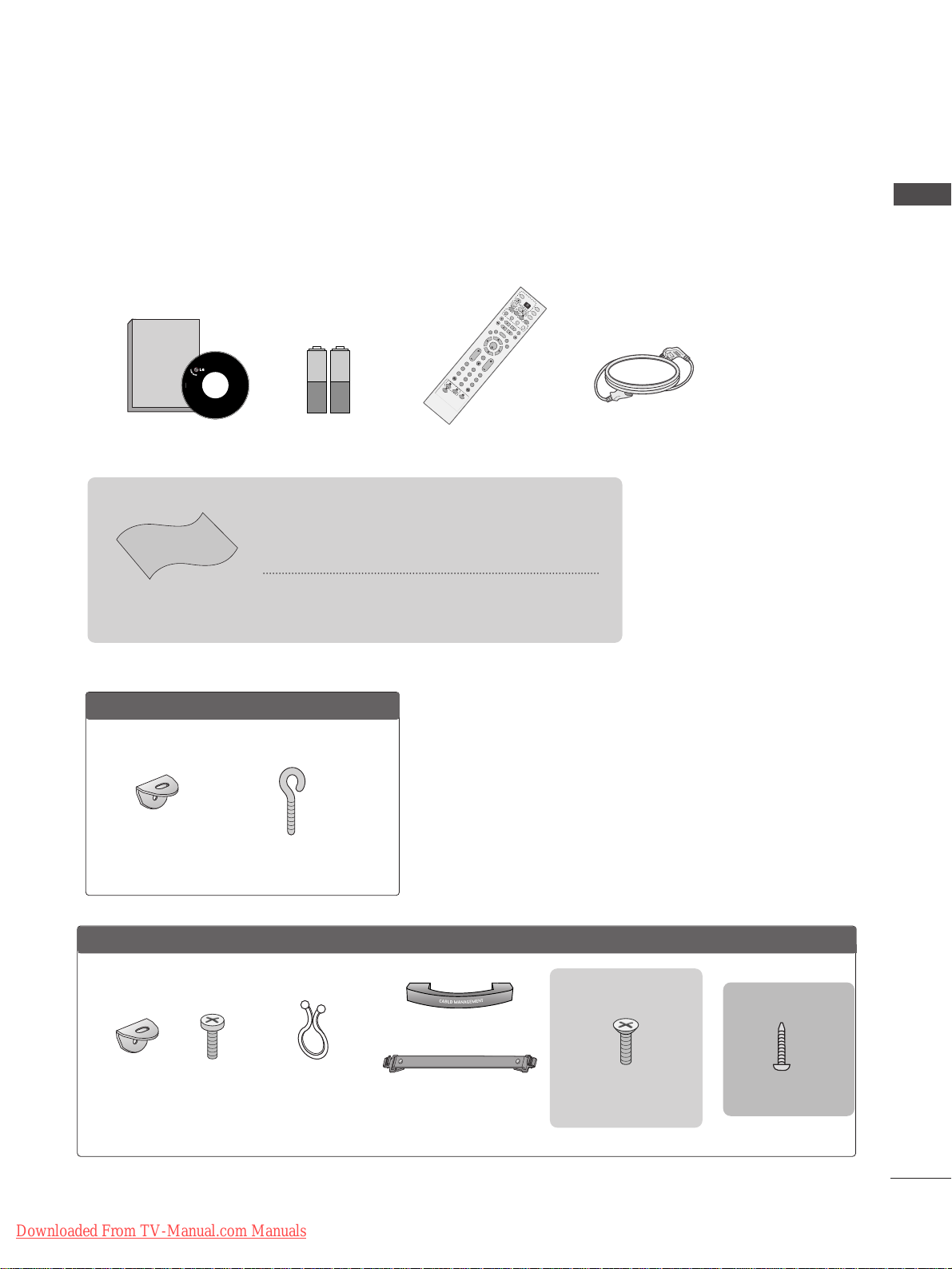
Ensure that the following accessories are included with your TV. If an accessory is missing, please contact the
dealer where you purchased the product.
Owner's
Manual
Owner’s manual
Owner’s Manual Batteries
OK
IN
P
U
T
M
O
D
E
TVT
V
D
V
D
RATIO
EXIT
V
O
L
P
O
S
IT
I
O
N
IN
D
E
X
P
R
PIP
SLE
EP
LIST
Q
.
V
I
E
W
I/I
I
M
E
N
U
S
IZ
E
V
C
R
P
IP
P
R
P
IP
P
R
+
P
I
P
I
N
P
U
T
P
O
W
E
R
123
456
789
0
FAV
R
E
V
E
A
L
?
T
EX
T
S
I
M
P
L
IN
K
I
N
P
U
T
M
U
T
E
T
IM
E
HOLD
OK
IN
P
U
T
M
O
D
E
T
V
T
V
D
V
D
RATIO
EXIT
V
O
L
P
O
S
IT
I
O
N
IN
DE
X
P
R
PIP
SLEEP
LIST
Q
.
V
I
E
W
I/
II
M
E
N
U
S
IZ
E
S
T
B
P
IP
P
R
-
P
IP
P
R
+
P
I
P
I
N
P
U
T
P
O
W
E
R
123
456
789
0
FAV
R
E
V
E
A
L
?
T
EX
T
S
I
M
P
L
IN
K
IN
P
U
T
M
U
TE
T
IM
E
HOLD
OK
IN
P
U
T
M
O
D
E
T
V
T
V
D
V
D
RATIO
EXIT
V
O
L
P
O
S
IT
IO
N
IN
D
E
X
P
R
P
IP
SLEE
P
LIST
Q
.
V
I
E
W
I/
II
M
E
N
U
S
IZ
E
V
C
R
P
IP
P
R
-
P
IP
P
R
+
P
I
P
I
N
P
U
T
P
O
W
E
R
123
456
789
0
FAV
R
E
V
E
A
L
?
T
E
X
T
S
I
M
P
L
IN
K
I
N
P
U
T
M
U
TE
T
IM
E
HO
LD
Remote Control Power Cord
Cable Management
2- TV Brackets
2- Wall Brackets
This feature is not
available for all models.
2-bolts
This feature is not
available
for all models.
Twister Holder
Arrange the wires with
the twister holder.
This feature is not available
for all models.
LLCCDD TTVV mmooddeellss
PPllaassmmaa TTVV mmooddeellss
2-Wall brackets
This feature is not available
for all models.
2-eye-bolts
This feature is not available
for all models.
4-bolts for stand assembly
Refer to p. 8
22 66”” ,, 3322”” ,, 33 77”” oonn ll yy
Polishing Cloth
Polishing cloth for use on the screen
This feature is not available
for all models.
*Lightly wipe any stains or fingerprints on the surface of the TV
with the polishing cloth.
Do not use excessive force. This may cause scratching or
discolouration.
or
3322LLBB99RR**oonnllyy
1-screw for stand fixing
Refer to p. 8
Downloaded From TV-Manual.com Manuals
Page 4
PREPARATION
Front Panel Controls................................................. 4
Back Panel Information ............................................ 6
Stand Installation....................................................... 8
AT TA CHING THE TV TO A DESK (Only 32LB9R*model) ........ 8
Attaching the TV to a Wall........................................9
Back Cover for Wire Arrangement....................... 10
Desktop Pedestal Installation ............................... 12
Wall Mount: Horizontal installation..................... 13
Antenna Connection............................................... 14
PICTURE CONTROL
Wa tching PIP(Picture-in-Picture) .............................46
Picture Size (Aspect Ratio)Control.........................48
Preset Picture Settings
- Picture Mode-Preset............................................50
- Auto Colour Tone Control(Warm/Medium/Cool)
51
Manual Picture Adjustment
- Picture Mode-User Option................................52
- Colour Tone - User Option...............................53
-
Picture Improvement Technology
...................54
Demo..................................................................55
Advanced - Cinema......................................................56
Advanced - Black(Darkness) Level...........................57
Picture Reset..................................................................58
Image Sticking Minimization(ISM) Method...........59
Low-Power Picture Mode............................................60
SOUND & LANGUAGE CONTROL
Auto Volume Leveler ....................................................61
Preset Sound Settings - Sound Mode....................62
Sound Setting Adjustment - User Mode ...............63
Balance ............................................................................64
TV Speakers On/Off Setup.......................................65
I/II
- Stereo/Dual Reception.......................................66
- NICAM Reception................................................67
- Speaker Sound Output Selection....................67
On-Screen Menu Language Selection
...................... 68
EXTERNAL EQUIPMENT SETUP
HD Receiver Setup .......................................................15
DVD Setup..................................................................... 18
VCR Setup..................................................................... 21
Other A/V Source Setup........................................... 24
External Stereo............................................................. 25
PC Setup.........................................................................26
- Screen Setup for PC Mode ...............................28
WATCHING TV /PROGRAMME CONTROL
Remote Control Key Functions..................................32
Turning on the TV....................................................... 34
Programme Selection ................................................. 34
Volume Adjustment......................................................34
On Screen Menus Selection and Adjustment ......35
Auto Programme Tuning............................................ 36
Manual Programme Tuning ....................................... 37
Fine Tuning .....................................................................38
Assigning a Station Name..........................................39
Programme Edit ........................................................... 40
Favourite Programme .................................................. 41
Selecting the Programme Table............................... 42
Key lock.......................................................................... 43
.................................................................. 44
PREPARATION
PICTURE CONTROL
WATCHING TV / PROGRAMME CONTROL
AACCCCEESSSSOORRII EESS
.....................................................1
2
CONTENTS
CONTENTS
Downloaded From TV-Manual.com Manuals
Page 5

3
CONTENTS
APPENDIX
Tr oubleshooting............................................................76
Maintenance .................................................................78
Product Specifications................................................79
Programming the Remote Control ........................ 81
TIME SETTING
Clock Setup....................................................................69
Auto On/Off Timer Setting .......................................70
Sleep Timer Setting......................................................71
Auto Shut-off Setting...................................................72
TELETEXT
Switch On/Off .............................................................73
SIMPLE Text....................................................................73
TOP Text .........................................................................74
FASTEXT .........................................................................74
Special Teletext Functions..........................................75
Downloaded From TV-Manual.com Manuals
Page 6
4
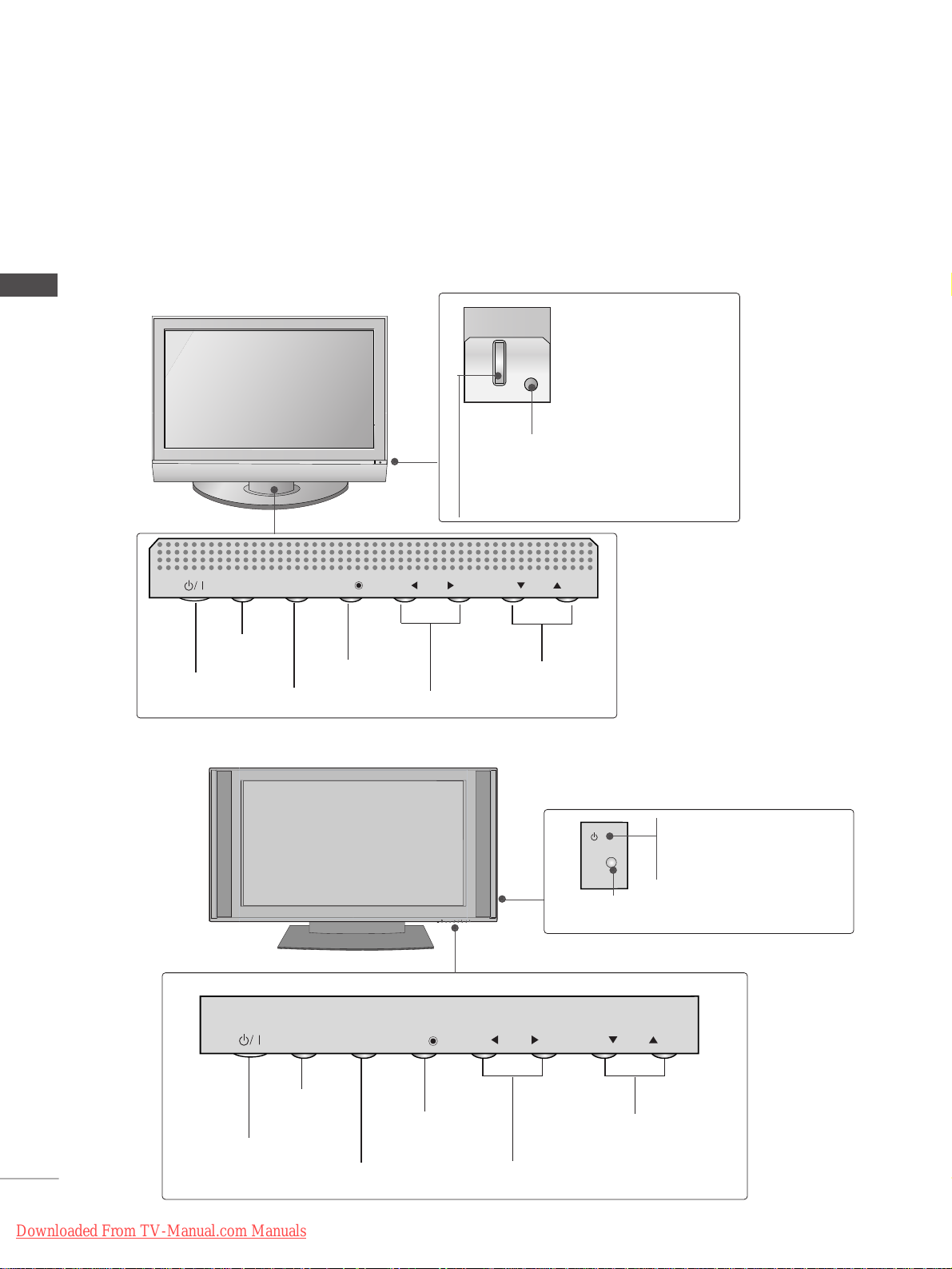
FRONT PANEL CONTROLS
PREPARATION
PREPARATION
■
This is a simplified representation of the front panel. Image shown may differ from your TV.
■
If your product has a protection film attached, remove the film and then wipe the product with a polishing
cloth.
Power/Standby Indicator
• illuminates red in standby mode.
• illuminates green when the TV is switched on.
Remote Control Sensor
Plasma TV Models
PRPR
VOLVOL
OKOK
MENUMENU
INPUTINPUT
Power/Standby Indicator
• illuminates red in standby mode.
• illuminates green when the TV is
switched on.
42/50PC5R*
42PC7R*
PROGRAMME
VOLUME
MENU
OK
INPUT
POWER
PR
VOL
OK
MENU
INPUT
PROGRAMME
VOLUME
MENU
OK
INPUT
POWER
PR
VOL
OK
MENU
INPUT
PR
VOL
OK
MENU
INPUT
Remote Control Sensor
Downloaded From TV-Manual.com Manuals
Page 7
5
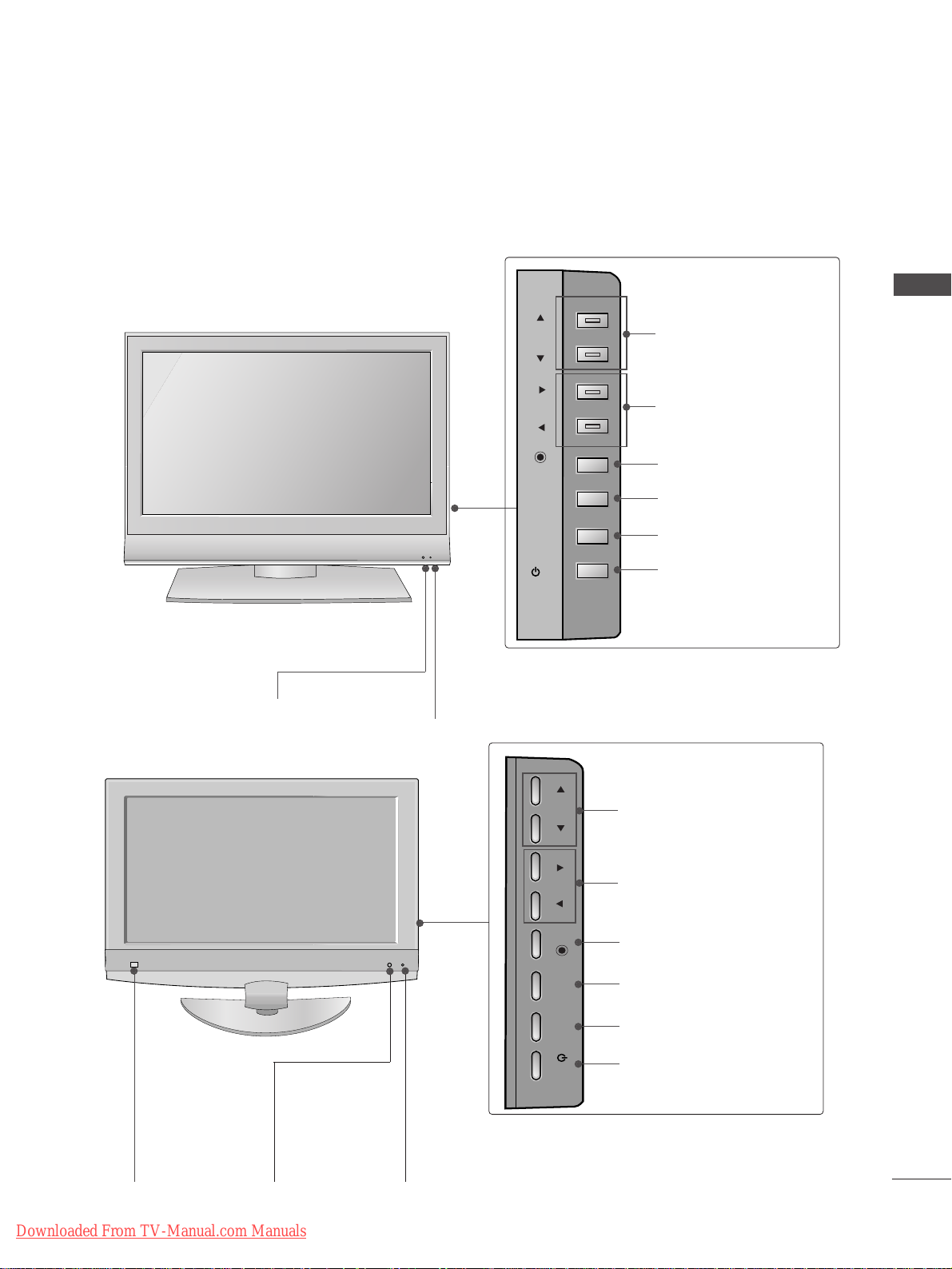
PREPARATION
LCD TV Models
Remote Control Sensor
Power/Standby Indicator
• illuminates red in standby mode.
• illuminates green when the TV is switched on.
PROGRAMME
VOLUME
OK
MENU
INPUT
POWER
26/32/37/42LC4R*
26/32/37/42LC7R*
32/42LB9R*
PR
VOL
OK
MENU
INPUT
/I
Remote Control
Sensor
Intelligent Eye
Adjusts picture
according to the
surrounding conditions.
Power/Standby Indicator
• illuminates red in standby mode.
• illuminates green when the TV is switched on.
PROGRAMME
VOLUME
OK
MENU
INPUT
POWER
PR
VOL
OK
MENU
INPUT
/I
Downloaded From TV-Manual.com Manuals
Page 8
6
PREPARATION
PREPARATION
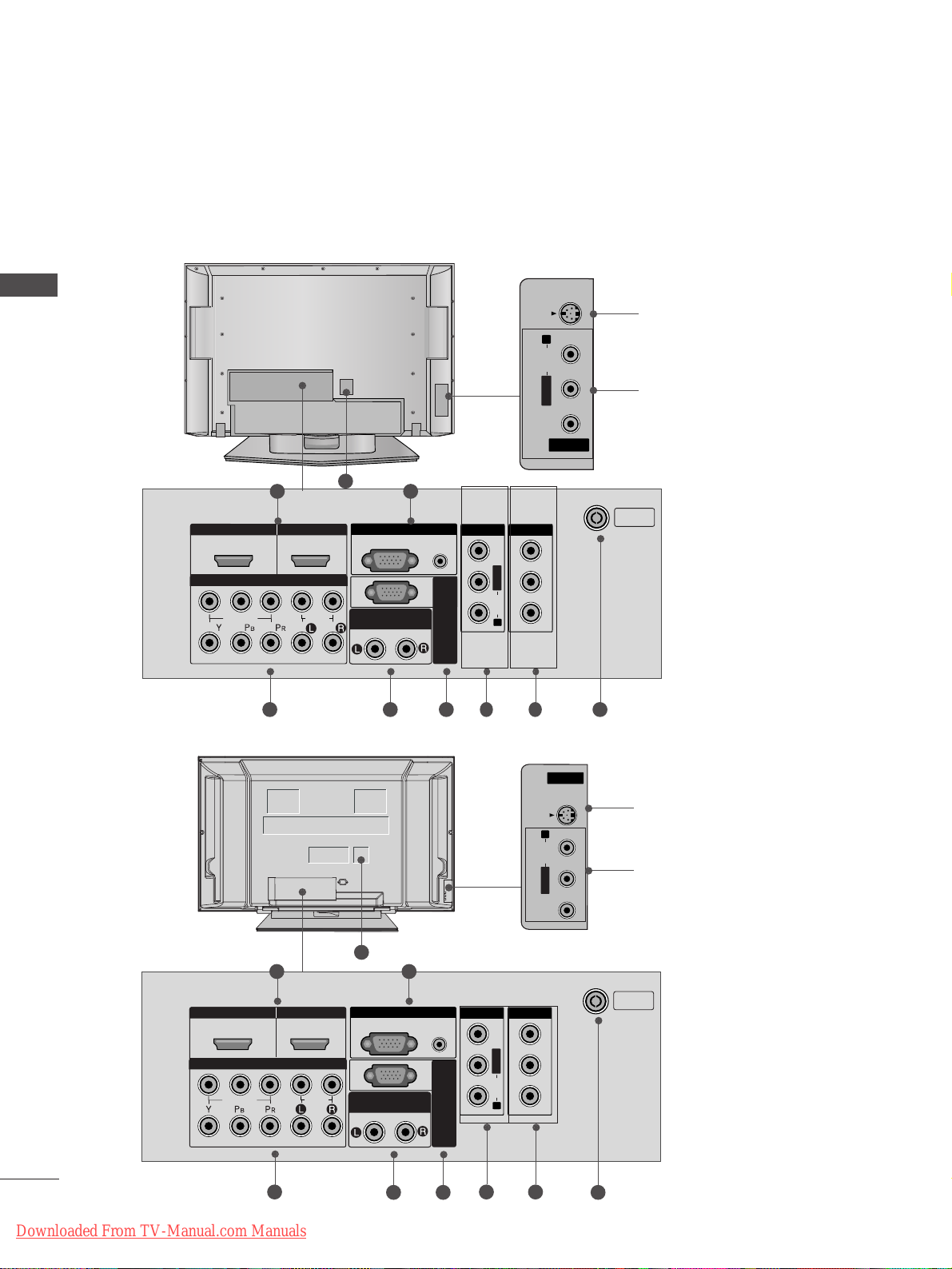
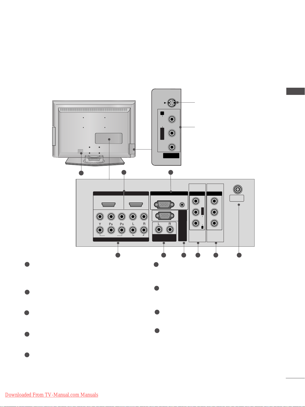
BACK PANEL INFORMATION
■
This is a simplified representation of the back panel. Image shown may differ from your TV.
Plasma TV Models
HDMI IN HDMI/DVI IN
1
1
2
2
VARIABLE AUDIO OUT
RGB IN
COMPONENT IN
AV IN 1 AV OUT
L/MONO
R
AUDIO
VIDEO
HDMI IN HDMI IN HDMI/DVI IN HDMI/DVI IN
1
1
2
2
VARIABLE ARIABLE AUDIO OUTAUDIO OUT
AUDIO
(RGB/DVI)
RGB
(PC)
RGB INRGB IN
COMPONENT INCOMPONENT IN
AUDIO
VIDEO
AV IN 1V IN 1 AV OUTV OUT
L/L/MONOMONO
R
AUDIOAUDIO
VIDEO
ANTENNA
IN
RS-232C IN
(CONTROL & SERVICE)
AV IN 3
L/MONO
R
AUDIO
VIDEO
S-VIDEO
21
4 53 6 8
9
7
S-Video Input
Connect S-Video out from an
S-VIDEO device.
Audio/Video Input
Connect audio/video output
from an external device to
these jacks.
AV IN 2V IN 2
L/MONOMONO
R
AUDIOAUDIO
VIDEO
S-VIDEOS-VIDEO
AV IN 2
L/MONO
R
AUDIO
VIDEO
S-VIDEO
HDMI IN HDMI/DVI IN
1
1
2
2
VARIABLE AUDIO OUT
RGB IN
COMPONENT IN
AV IN 1 AV OUT
L/MONO
R
AUDIO
VIDEO
HDMI IN
HDMI/DVI IN
ARIABLE
AUDIO OUT
RGB IN
COMPONENT IN
V IN 1
V OUT
L/
MONO
AUDIO
AV IN 2
L/MONO
R
AUDIO
VIDEO
S-VIDEO
21
4 5
3 6
8
9
7
S-Video Input
Connect S-Video out from an
S-VIDEO device.
Audio/Video Input
Connect audio/video output
from an external device to
these jacks.
AV IN 2V IN 2
L/L/MONOMONO
R
AUDIO
VIDEO
S-VIDEO
42/50PC5R*
42PC7R*
Downloaded From TV-Manual.com Manuals
1
2
HDMI/DVI IN
1
COMPONENT IN
VIDEO
HDMI IN
2
AUDIO
VARIABLE
RGB IN
RGB
(PC)
AUDIO OUT
AUDIO
(RGB/DVI)
RS-232C IN
(CONTROL & SERVICE)
AV IN 1
AV OUT
VIDEO
MONO
L/
AUDIO
R
ANTENNA
IN
Page 9
7
PREPARATION
HDMI Input
Connect a HDMI signal to HDMI IN.
Or DVI(VIDEO)signal to HDMI/DVI port with DVI
to HDMI cable.
RGB/Audio Input
Connect the monitor output from a PC to the
appropriate input port.
Component Input
Connect a component video/audio device to
these jacks.
Variable Audio Output
Connect an external amplifier or add a subwoofer
to your surround sound system.
RS-232C Input
(CONTROL&SERVICE) Por t
Connect the serial port of the control devices to
the RS-232C jack.
(This feature is not available for all models.)
Audio/Video Input (AV IN 1)
Connect audio/video output from an external
device to these jacks.
AV Output
Connect second TV or monitor to the AV OUT
socket on the
TV.
Antenna Input
Connect RF antenna (UHF) to this jack.
Power Cord Socket
This TV operates on an AC power. The voltage is
indicated on the Specifications page. Never
attempt to operate the TV on DC power.
1
2
3
4
5
6
7
8
9
AV IN 2
L/MONO
R
AUDIO
VIDEO
S-VIDEO
HDMI IN HDMI/DVI IN
1
1
2
2
VARIABLE
AUDIO OUT
RGB IN
COMPONENT IN
AV IN 1 AV OUT
L/MONO
R
AUDIO
VIDEO
HDMI IN HDMI IN HDMI/DVI IN HDMI/DVI IN
1
1
2
2
VARIABLEARIABLE
AUDIO OUTAUDIO OUT
AUDIO
(RGB/DVI)
RGB
(PC)
RGB INRGB IN
COMPONENT INCOMPONENT IN
AUDIO
VIDEO
AV IN 1V IN 1 AV OUTV OUT
L/L/MONOMONO
R
AUDIOAUDIO
VIDEOVIDEO
ANTENNA
IN
RS-232C IN
(CONTROL & SERVICE)
21
43 65 87
S-Video Input
Connect S-Video out from an
S-VIDEO device.
Audio/Video Input
Connect audio/video output
from an external device to
these jacks.
AV IN 2V IN 2
L/L/MONOMONO
R
AUDIOAUDIO
VIDEOVIDEO
S-VIDEOS-VIDEO
AV IN 2
L/MONO
R
AUDIO
VIDEO
S-VIDEO
9
LCD TV Models
Downloaded From TV-Manual.com Manuals
Page 10
8
PREPARATION
PREPARATION
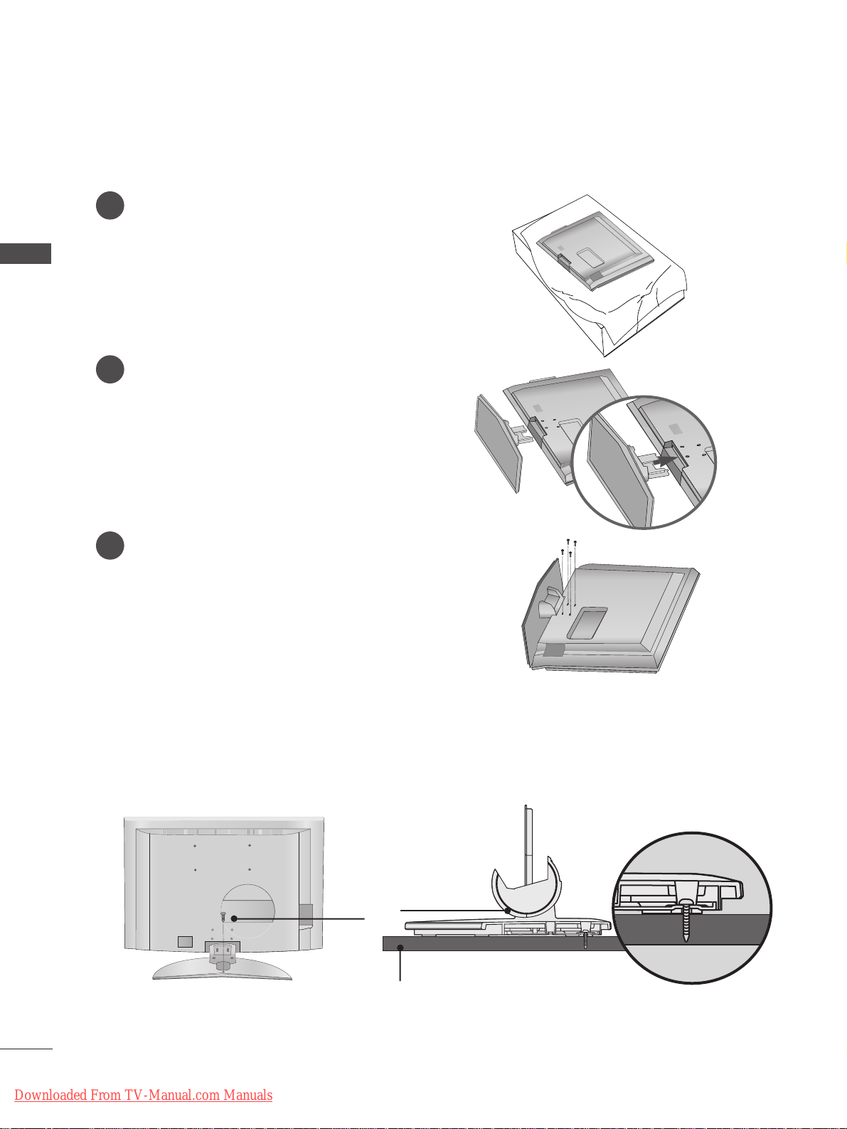
STAND INSTALLATION (Only 26, 32,37 inch LCD TV models)
1
2
3
Carefully place the TV screen side down on a
cushioned surface to protect the screen from
damage.
Assemble the TV as shown.
Fix the 4 bolts securely using the holes in the
back of the TV.
ATTA CHING THE TV TO A DESK (Only 32LB9R
*
model)
If you wish to attach the TV to a desk, it must be securely fastened to the desk using a metal screw (as shown
below). Failure to securely attach the TV may result in the TV falling; which may cause damage to the TV and
serious personal injury.
1-Screw
Stand
Desk
Downloaded From TV-Manual.com Manuals
Page 11
9
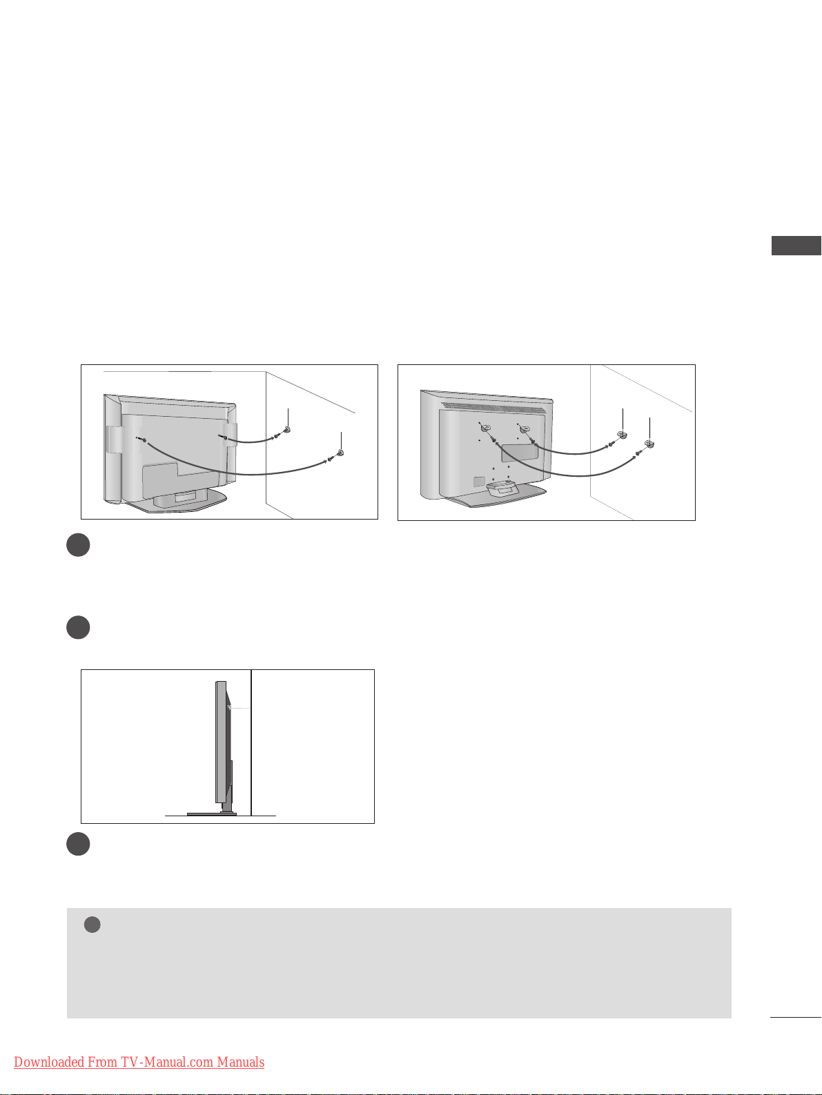
ATTA CHING THE TV TO A WALL
(This feature is not available for all models.)
PREPARATION
Plasma TV models LCD TV models
2
1
■
Position the TV close to the wall to avoid the possibility of it falling when pushed.
■
The instructions shown below are a safer way to
set up the TV, which is to fix it to the wall, avoiding the
possibility of it falling forwards if pulled. This will prevent the TV from falling forward and causing injury.
This will also prevent the TV from damage. Ensure that children do not climb or hang from the TV.
NOTE
!
G
When moving the TV undo the cords first.
G
Use a platform or cabinet string and large enough to support the size and weight of the TV.
G
To use the TV safely make sure that the height of the bracket on the wall and on the TV is the same.
2
3
1
1
2
Use the eye-bolts or TV brackets/bolts to fix the product to the wall as shown in the picture.
(If your TV has bolts in the eyebolts, loosen then bolts.)
* Insert the eye-bolts or TV brackets/bolts and tighten them securely in the upper holes.
Secure the wall brackets with bolts (must purchase seperately) to the wall.
Ensure that both brackets are even.
3
Use a strong cord (must purchase separately) to secure the TV.
Secure the cord in such a way that it becomes taught when the TV is in position.
Downloaded From TV-Manual.com Manuals
Page 12
10
BACK COVER FOR WIRE ARRANGEMENT
PREPARATION
PREPARATION
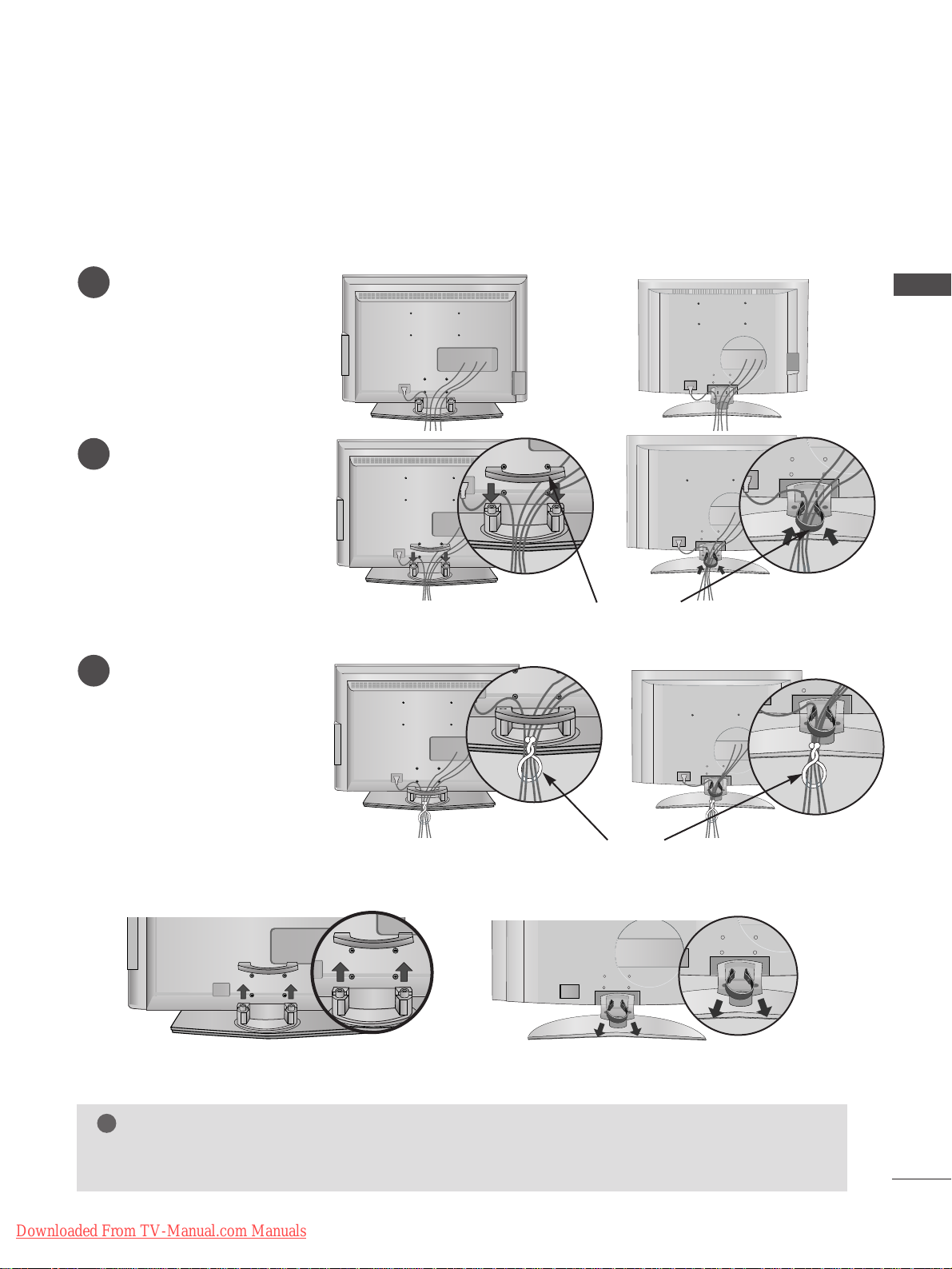
Plasma TV models
■
These models have two cable arrangement methods according to the stand type.
Connect the cables as necessary.
To connect additional equipment, see the External
equipment Setup section of the manual.
Reinstall the
CCAABBLLEE MMAANNAAGG EE MMEENN TT
as shown.
2
1
3
CABLE MANAGEMENT
Grip the CABLE MANAGEMENT and push the cover upwards.
Stand type 1
Stand type 2
Arrange the cables as shown picture.
Downloaded From TV-Manual.com Manuals
Page 13
11
PREPARATION
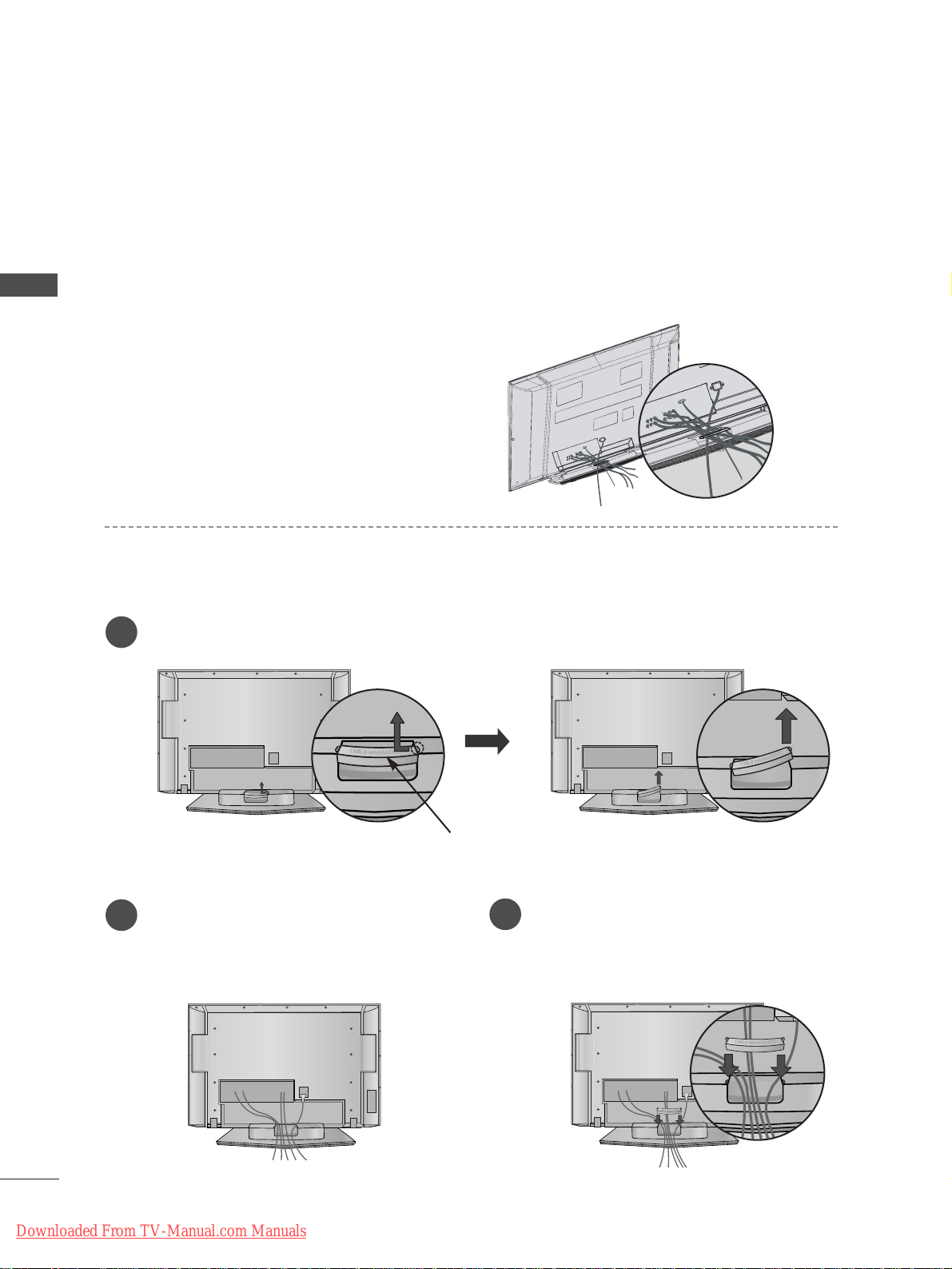
LCD TV models
Connect the cables as necessary.
To connect additional
equipment, see the External
equipment Setup section.
1
Install the
CCAABBLL EE MMAANN--
AAGGEEMMEENN TT
as shown.
2
Bundle the cables using the
supplied twister holder.
(
This feature is not available
for all models.)
3
Hold the
CCAABBLLEE MMAANNAAGG EE MMEENN TT
with both hands and pull it upward.
NOTE
!
GG
Do not use the CABLE MANAGEMENT to lift the TV.
- If the TV is dropped, you may be injured or the TV may be damaged.
How to remove the cable management
CABLE MANAGEMENT
TWIST HOLDER
or
or
or
or
(Insert it as pushing the loops on the
both sides of the cable management.)
(Pull it out as holding the loops on the both
sides of the cable management.)
Downloaded From TV-Manual.com Manuals
Page 14
12
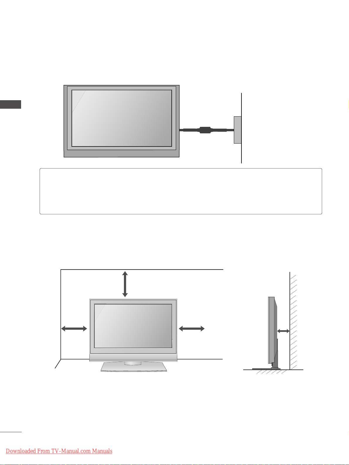
■
The TV can be installed in various ways such as on a wall, or on a desktop etc.
■
The TV is designed to be mounted horizontally.
PREPARATION
PREPARATION
DESKTOP PEDESTAL INSTALLATION
For adequate ventilation allow a clearance of 4” (10cm) all around the TV .
4 inches
4 inches
4 inches
4 inches
Power Supply
Circuit breaker
EARTHING
Ensure that you connect the earth wire to prevent possible electric shock. If grounding methods are not
possible, have a qualified electrician install a separate circuit breaker.
Do not try to earth the TV by connecting it to telephone wires, lightening rods or gas pipes.
Downloaded From TV-Manual.com Manuals
Page 15
13
PREPARATION
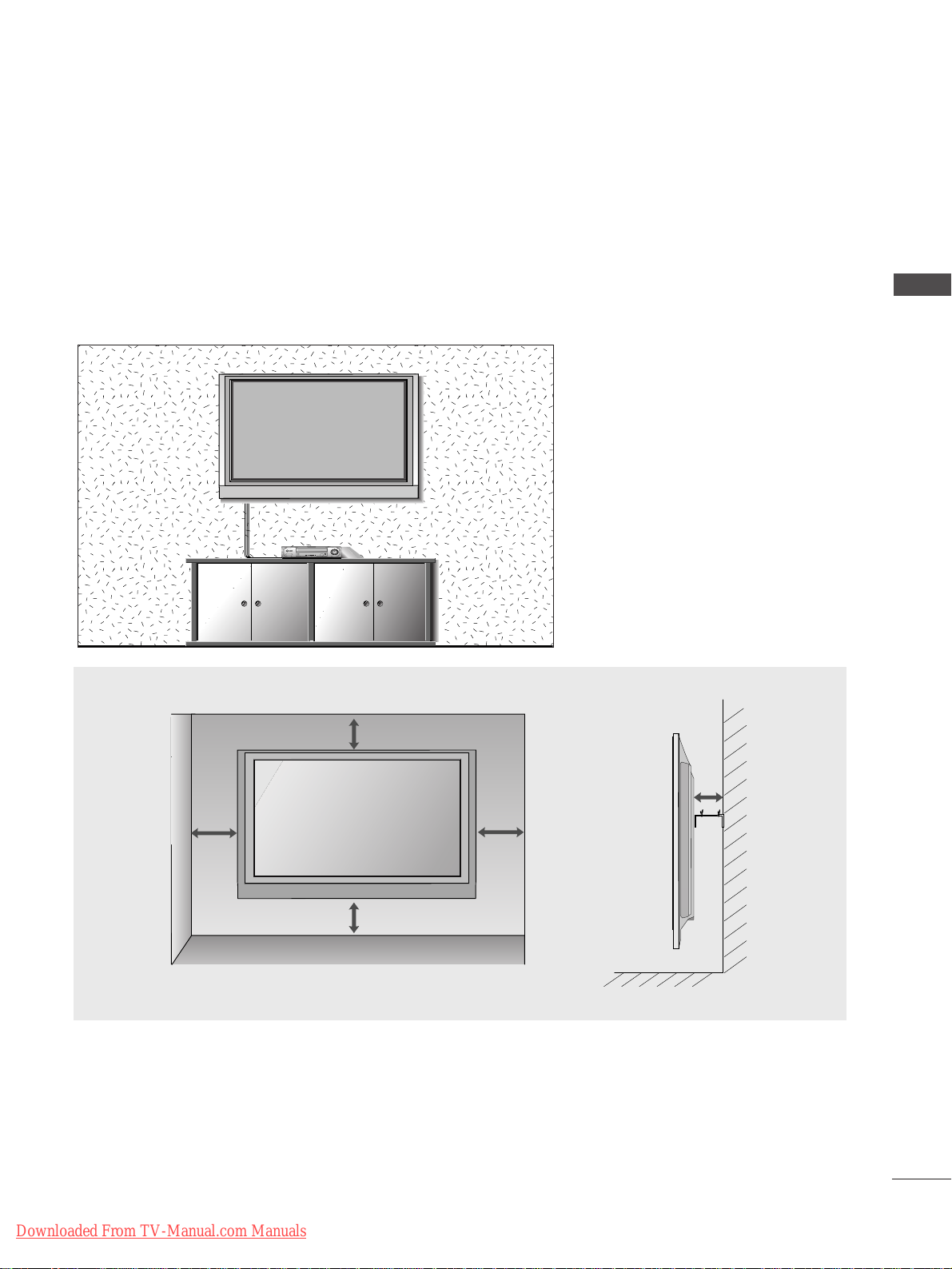
WALL MOUNT: HORIZONTAL INSTALLATION
For adequate ventilation allow a clearance of 4” (10cm) all around the TV. Detailed installation instruc-tions
are available from your dealer, see the optional Tilt Wall Mounting Bracket Installation and Setup Guide.
4 inches
4 inches
4 inches
4 inches
4 inches
Downloaded From TV-Manual.com Manuals
Page 16
14
PREPARATION
AV IN 3
L/MONO
R
AUDIO
VIDEO
S-VIDEO
AV IN 3
L/MONO
R
AUDIO
VIDEO
S-VIDEO
AV IN 2
L/MONO
R
AUDIO
VIDEO
S-VIDEO
AV IN 2
L/MONO
R
AUDIO
VIDEO
S-VIDEO
PREPARATION
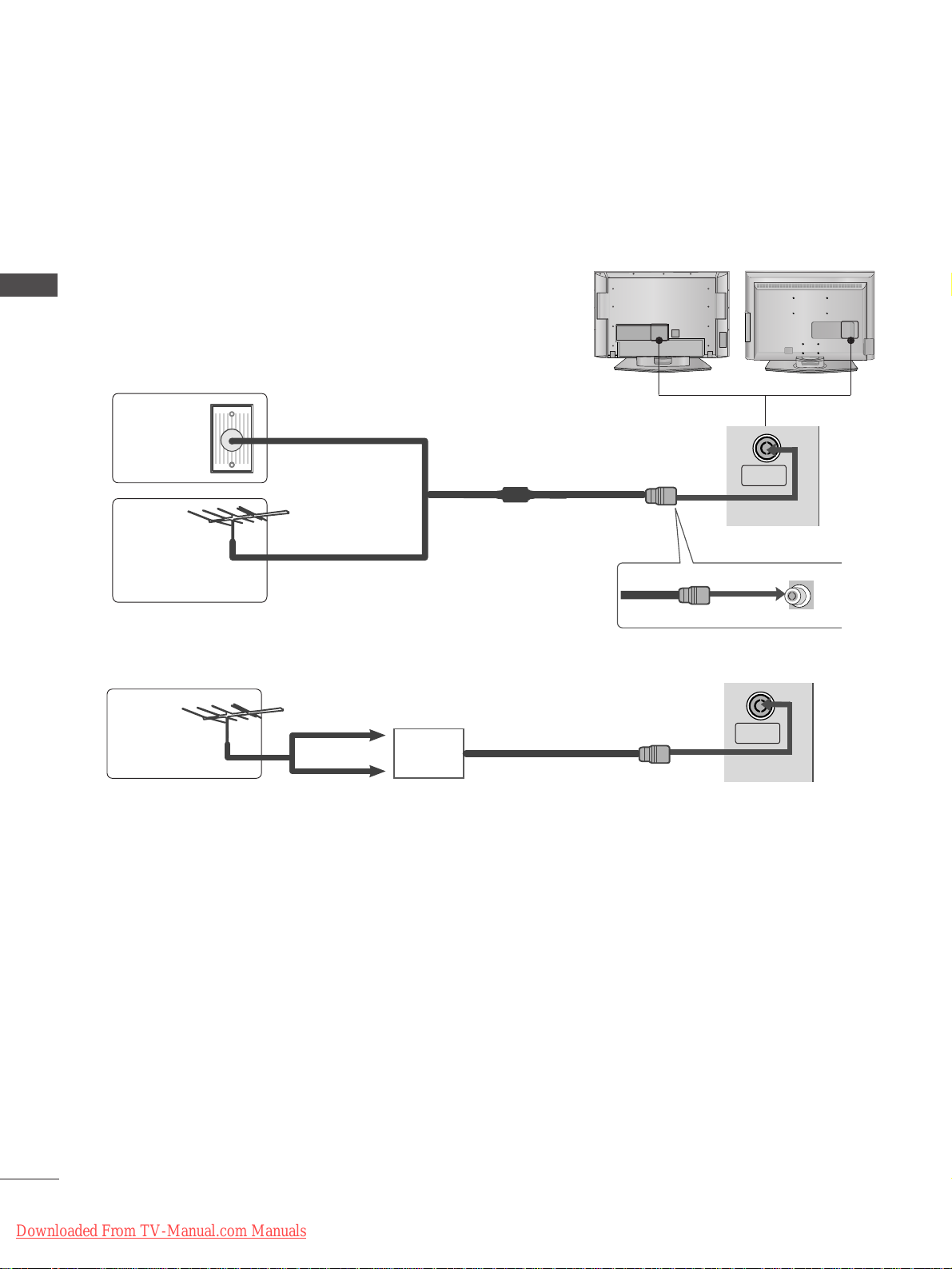
ANTENNA CONNECTION
■
For optimum picture quality, adjust antenna direction.
■
An antenna cable and converter are not supplied.
Multi-family Dwellings/Apartments
(Connect to wall antenna socket)
Single-family Dwellings /Houses
(Connect to wall jack for outdoor antenna)
Outdoor
Antenna
Wall
Antenna
Socket
RF Coaxial Wire (75 ohm)
Antenna
UHF
Signal
Amplifier
VHF
■
In poor signal areas, to achieve better picture quality it may be necessary to install a signal amplifier to the
antenna as shown above.
■
If signal needs to be split for two TVs, use an antenna signal splitter for connection.
■
It is recommended that 42PC5RH / 42PC5RVH / 50PC5RH / 42PC7RVH model only be used at an altitude
of less than 6561 feet (2000m) to get the best quality picture and sound.
■
To prevent damage do not connect to the mains outlet until all connections are made between the devices.
ANTENNA
IN
ANTENNA
IN
Downloaded From TV-Manual.com Manuals
Page 17
15
EXTERNAL EQUIPMENT SETUP
HDMI IN HDMI DVI IN
1
2
COMPONENT INCOMPONENT IN
AUDIO
VIDEO
HDMI IN HDMI DVI IN
HDMI/DVI IN
1
1 2
EXTERNAL EQUIPMENT SETUP
HD RECEIVER SETUP
Connecting with a component cable
Connect the video outputs (Y, PB
, PR
)
of the digital TV
top box to the
CCOOMMPPOONNEENNTT IINN VVIIDDEEOO
jacks on the
TV.
Connect the audio output of the digital set-top box to
the
CCOOMMPPOONNEENNTT IINN AAUU DDIIOO
jacks on the TV.
Turn on the digital set-top box.
(
Refer to the owner’s manual for the digital set-top box.
)
Select
Component1 input source using the
IINNPPUU TT
button on the remote control.
If connected to
CCOOMMPPOONNEENNTT IINN22
, select
Component2 input source.
2
3
4
1
■
To avoid damaging any equipment, never plug in any power cords until you have finished connecting all equipment.
■
This section on EXTERNAL EQUIPMENT SETUP mainly uses diagrams for the LCD TV models.
Signal
480i/576i
480p/576p
720p/1080i
10 8 0 p
Component
Yes
Yes
Yes
No
HDMI1/2
No
Yes
Yes
Yes
(except VGA Models)
Downloaded From TV-Manual.com Manuals
Page 18
HDMI IN HDMI DVI IN
1
2
COMPONENT IN
HDMI IN HDMI DVI IN
HDMI/DVI IN
1
HDMI IN HDMI DVI IN
HDMI IN HDMI IN HDMI/DVI IN HDMI/DVI IN
1 2
1
16
EXTERNAL EQUIPMENT SETUP
EXTERNAL EQUIPMENT SETUP
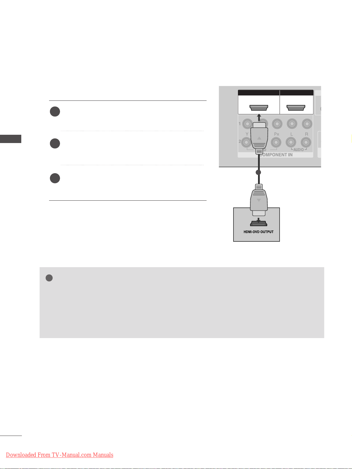
Connecting a set-top box with an HDMI cable
Connect the HDMI output of the digital set-top box to
the
HH DDMMII//DDVVII IINN 11
or
HH DDMMII IINN 22
jack on the TV.
Select
HDMI1 or HDMI2 input source using the
IINNPPUU TT
button on the remote control.
Turn on the digital set-top box.
(
Refer to the owner’s manual for the digital set-top box.
)
2
3
1
GG
TV can receive the video and audio signal simultaneously with using a HDMI cable.
GG
If the digital set-top box supports Auto HDMI function, the output resolution of the source device will
be automatically TV to 1280x720p.
GG
If the digital set-top box player does not support Auto HDMI, you need to TV the output resolution
appropriately.
To get the best picture quality, adjust the output resolution of the source device to 1280x720p.
NOTE
!
Downloaded From TV-Manual.com Manuals
Page 19
AV IN 1AV IN 1 AV OUTAV OUT
AUDIO
(RGB/DVI)
RGB
(PC)
HDMI IN HDMI DVI IN
AUDIO
(RGB/DVI)
RGB(PC)
RGB IN
HDMI/DVI IN
1
L/MONO
1
2
17
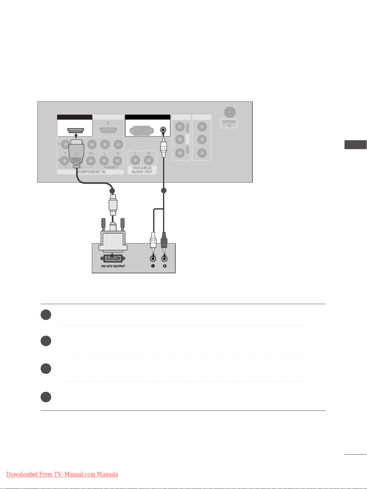
EXTERNAL EQUIPMENT SETUP
Connect the DVI output of the digital set-top box to the
HH DDMMII//DDVVII IINN 11
jack on the TV.
Connect the audio output of the digital set-top box to the
AAUUDDIIOO((RRGGBB//DDVVII))
jack on the TV.
Turn on the digital set-top box. (Refer to the owner’s manual for the digital set-top box.
)
Select
HDMI1 input source using the
IINNPPUU TT
button on the remote control.
2
3
4
1
Connecting with a HDMI to DVI cable
Downloaded From TV-Manual.com Manuals
Page 20
RG
HDMI IN HDMI DVI IN
L/MONO
R
AUDIO
VIDEO
S-VIDEO
1
2
COMPONENT INCOMPONENT IN
AUDIO
VIDEO
1 2
18
DVD SETUP
EXTERNAL EQUIPMENT SETUP
EXTERNAL EQUIPMENT SETUP
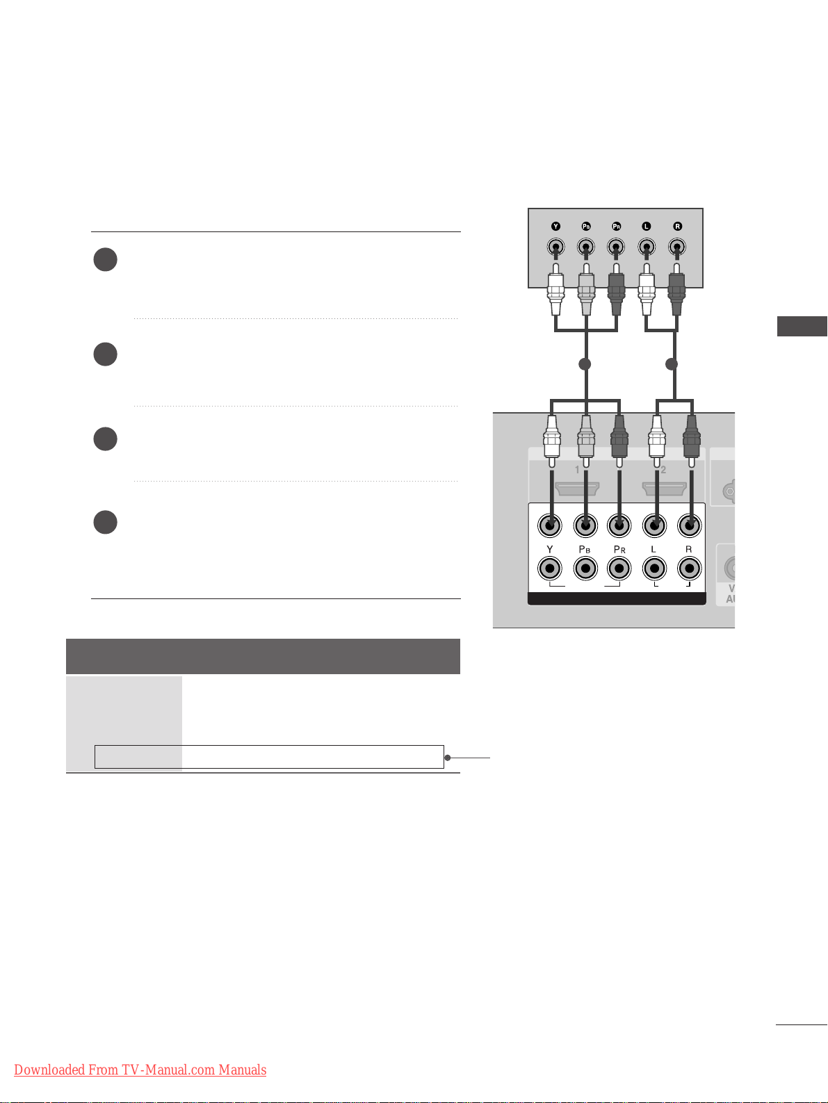
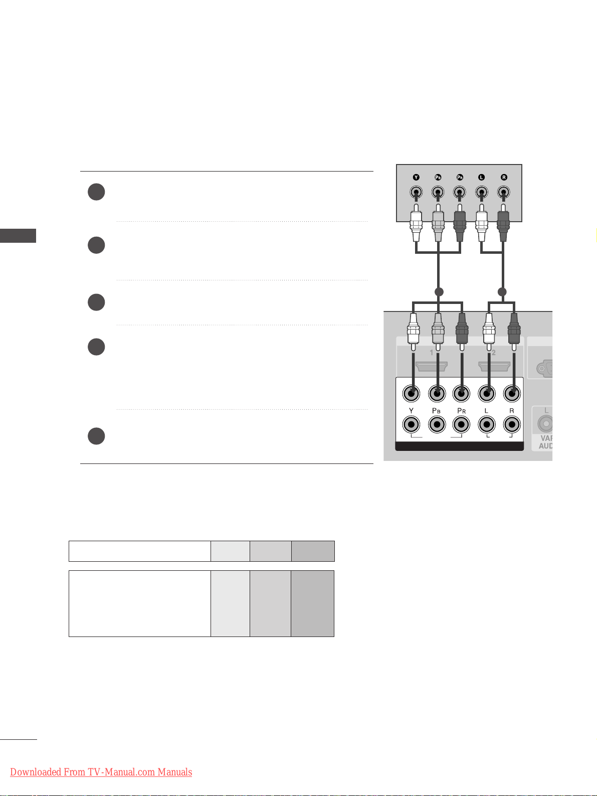
Connecting with a component cable
Component Input ports
To achieve better picture quality, connect a DVD player to the component input ports as shown below.
Component ports on the TV
YPB PR
Video output ports
on DVD player
Y
Y
Y
Y
PB
B-Y
Cb
Pb
P
R
R-Y
Cr
Pr
Connect the video outputs (Y, PB
, PR
)
of the DVD to the
CCOOMMPPOONNEENNTT IINN VVIIDDEEOO
jacks on the TV.
Connect the audio outputs of the DVD to the
CCOOMMPP OO--
NNEENN TT IINN AAUUDD IIOO
jacks on the TV.
Tu r n on the DVD player, insert a DVD.
Select
Component1
input source using the
IINNPPUU TT
button
on the remote control.
If connected to
CCOO MMPPOONNEENN TT IINN22
, select Component2
input source.
Refer to the DVD player's manual for operating instructions.
2
3
4
5
1
Downloaded From TV-Manual.com Manuals
Page 21
19
EXTERNAL EQUIPMENT SETUP
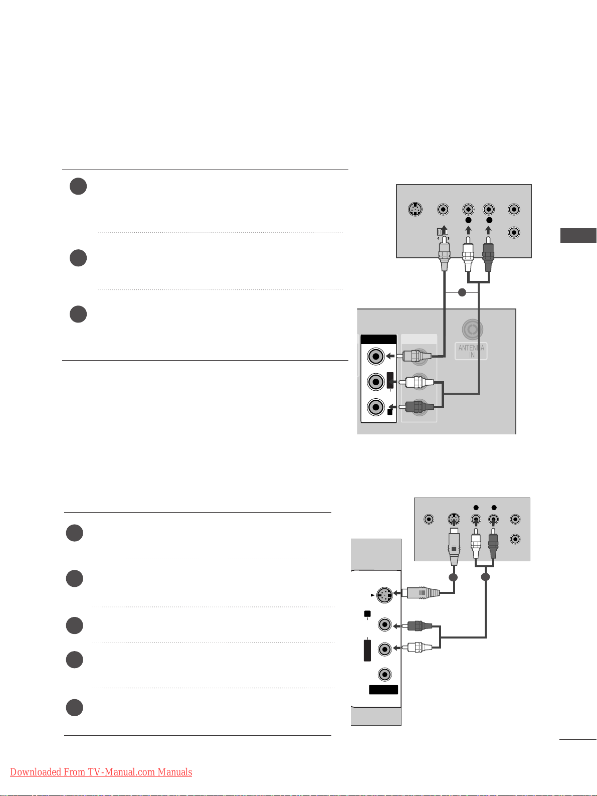
Connecting with a RCA cable
Connect the
AAUU DDIIOO/VVIIDDEEOO
jacks between TV and DVD
player. Match the jack colours (Video = yellow, Audio Left =
white, and Audio Right = red)
Insert a DVD into the DVD player and press PLAY on the
DVD player. (Refer to the DVD player owner’s manual.
)
Select
AV 1 input source using the
IINNPPUU TT
button on the
remote control.
If connected to
AAVV IINN22
, select
AV 2 input source.
2
3
1
Connecting with a S-Video cable
Connect the S-VIDEO output of the DVD to the
SS --
VVIIDDEEOO
input on the TV.
Connect the audio outputs of the DVD to the
AAUU DDIIOO
input jacks on the TV.
Tu r n on the DVD player, insert a DVD.
Select
AV 2 input source using the
IINNPPUU TT
button on
the remote control.
Refer to the DVD player's manual for operating
instructions.
2
3
4
5
1
AV IN 1AV IN 1 AV OUTAV OUT
L/MONO
AV IN 1
L
R
S-VIDEO
VIDEO
OUTPUT
SWITCH
ANT IN
ANT OUT
L/L/MONOMONO
R
AUDIOAUDIO
VIDEOVIDEO
1
AV IN 2
L/MONOMONO
R
AUDIO
VIDEOVIDEO
S-VIDEO
L R
S-VIDEOVIDEO
OUTPUT
SWITCH
ANT IN
ANT OUT
1
2
Downloaded From TV-Manual.com Manuals
Page 22
20
EXTERNAL EQUIPMENT SETUP
EXTERNAL EQUIPMENT SETUP
HDMI IN HDMI DVI IN
HDMI IN HDMI DVI IN
HDMI IN HDMI DVI IN
AV IN 2
L/MONO
R
AUDIO
VIDEO
S-VIDEO
1
2
COMPONENT IN
HDMI IN HDMI IN HDMI/DVI IN HDMI/DVI IN
1 2
1
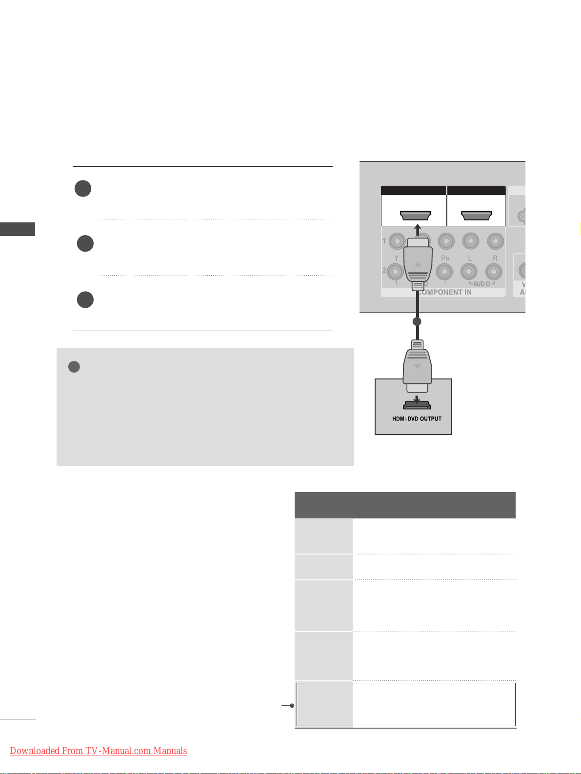
Connecting the HDMI cable
Connect the HDMI output of the DVD to the
HH DDMMII//DDVVII IINN 11
or
HH DDMMII IINN 22
jack on the TV.
Select
HDMI1 or HDMI2 input source using the
IINNPPUU TT
button on the remote control.
Refer to the DVD player's manual for operating
instructions.
1
GG
The TV can receive video and audio signals simultaneously when
using a HDMI cable.
GG
If the DVD player supports Auto HDMI function, the output resolution of the source device will be automatically TV to 1280x720p.
GG
If the DVD player does not support Auto HDMI, you must TV the
output resolution appropriately.
To get the best picture quality, adjust the output resolution of the
source device to 1280x720p.
NOTE
!
2
3
Resolution
720x480
720x576
12 8 0x720
19 2 0x1080i
19 2 0x1080p
Supported Display Resolution (HDMI-DTV mode)
Horizontal Vertical
Frequency(kHz) Frequency(Hz)
31.47 59.94
31.50 60.00
31.25 50.00
44.96 59.94
45.00 60.00
37. 50 50.00
33.72 59.94
33.75 60.00
28.125 50.00
67. 432 59.94
67. 5 60
56.25 50
(except VGA Models)
Downloaded From TV-Manual.com Manuals
Page 23
AV IN 1AV IN 1 AV OUTAV OUT
AUDIO
(RGB/DVI)
L/MONO
R
AUDIO
S-VIDEO
ANTENNA
IN
OUTPUT
SWITCH
ANT IN
R
S-VIDEO VIDEO
ANT OUT
L
L/MONO
Wall Jack
Antenna
1
2
21
VCR SETUP
EXTERNAL EQUIPMENT SETUP
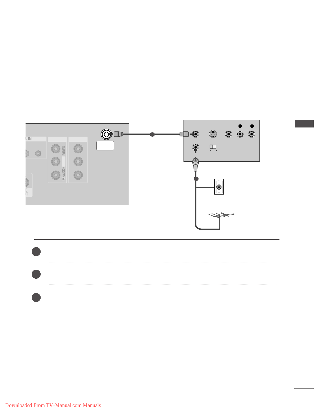
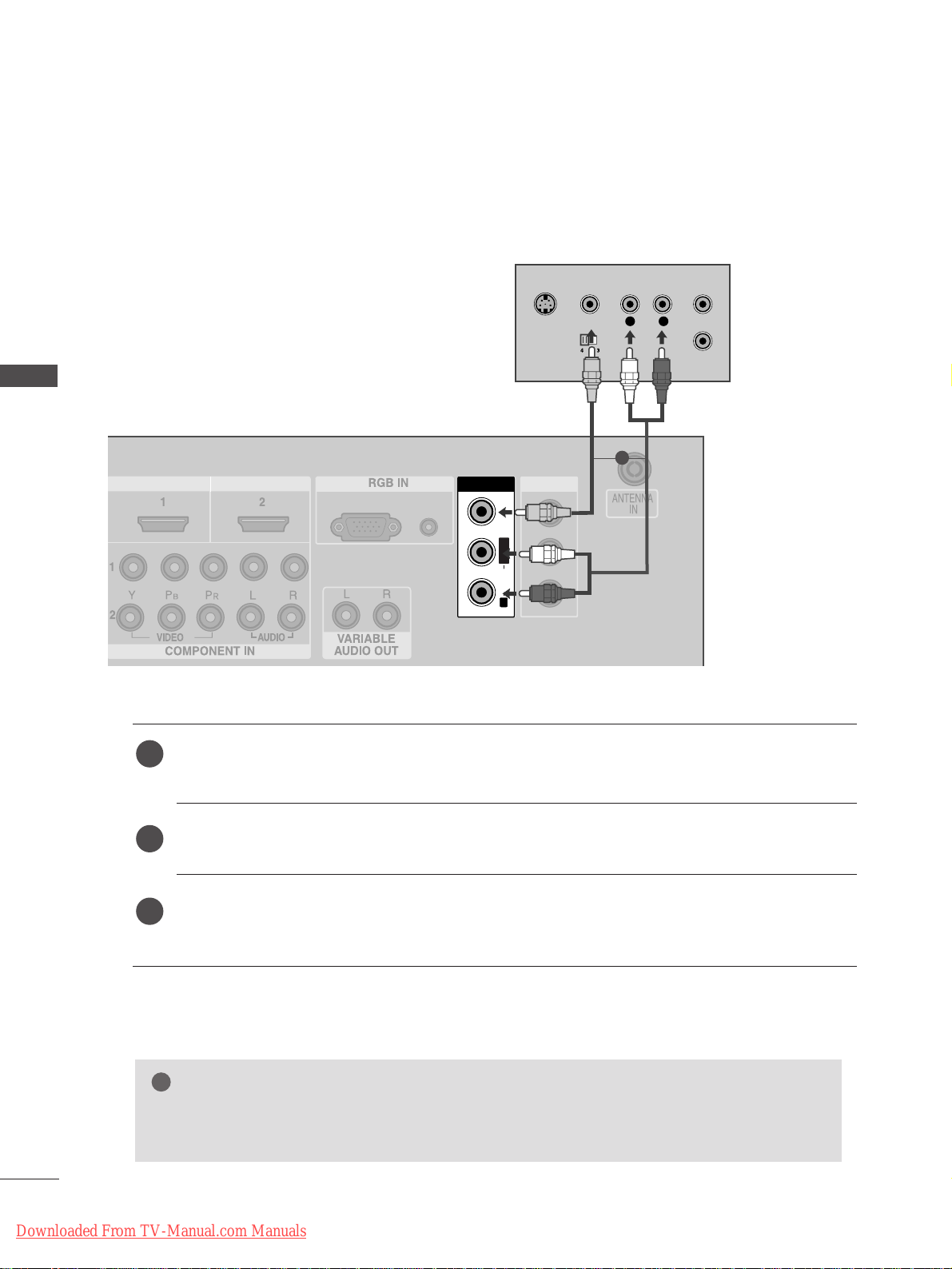
Connecting with a RF cable
■
To avoid picture noise (interference), allow adequate distance between the VCR and TV.
■
Typically a frozen still picture from a VCR. If 4:3 picture format is used for an extended period the fixed
images on the sides of the screen may remain visible.
Connect the
AANNTT OOUU TT
socket of the VCR to the
AANNTTEENNNN AA IINN
socket on the TV.
Connect the antenna cable to the
AANNTT IINN
socket of the VCR.
Press the
PP LL AA YY
button on the VCR and match the appropriate programme between the TV and VCR for
viewing.
1
2
2
3
1
Downloaded From TV-Manual.com Manuals
Page 24
Connecting with a RCA cable
AV IN 1AV IN 1 AV OUTAV OUT
L/MONO
AUDIO
(RGB/DVI)
RGB
(PC)
HDMI IN HDMI DVI IN
AV IN 2
L/MONO
R
AUDIO
VIDEO
S-VIDEO
AV IN 1
L
R
S-VIDEO
VIDEO
OUTPUT
SWITCH
ANT IN
ANT OUT
L/L/MONOMONO
R
AUDIOAUDIO
VIDEOVIDEO
Connect the
AAUU DDIIOO/VVIIDDEEOO
jacks between TV and VCR. Match the jack colours (Video = yellow,
Audio Left = white, and Audio Right = red)
Insert a video tape into the VCR and press PLAY on the VCR. (Refer to the VCR owner’s manual.
)
Select
AV 1 input source using the
IINNPPUU TT
button on the remote control.
If connected to
AAVV IINN22
, select
AV 2 input source.
1
2
3
GG
If you have a mono VCR, connect the audio cable from the VCR to the
AAUUDDIIOO LL//MMOONNOO
jack
of the TV.
NOTE
!
1
22
EXTERNAL EQUIPMENT SETUP
EXTERNAL EQUIPMENT SETUP
Downloaded From TV-Manual.com Manuals
Page 25
23
EXTERNAL EQUIPMENT SETUP
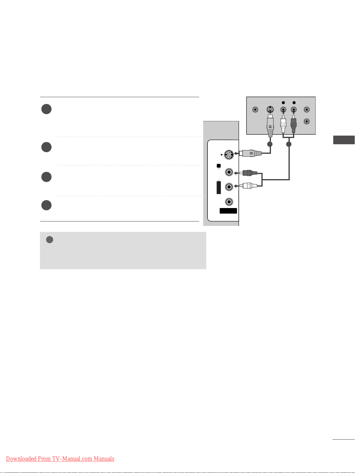
GG
If both S-VIDEO and VIDEO sockets have been conneced to
the S-VHS VCR simultaneously, only the S-VIDEO can be
received.
NOTE
!
AV IN 2
L/MONOMONO
R
AUDIO
VIDEOVIDEO
S-VIDEO
L R
S-VIDEOVIDEO
OUTPUT
SWITCH
ANT IN
ANT OUT
Connecting with a S-Video cable
Connect the S-VIDEO output of the VCR to the
SS --
VVIIDD EE OO
input on the TV. The picture quality is
improved; compared to normal composite (RCA cable)
input.
Connect the audio outputs of the VCR to the
AAUU DDIIOO
input jacks on the TV.
Insert a video tape into the VCR and press PLAY on
the VCR. (Refer to the VCR owner’s manual.)
Select
AV 2 input source using the
IINNPPUU TT
button on
the remote control.
2
3
4
1
1 2
Downloaded From TV-Manual.com Manuals
Page 26
AV IN 2V IN 2
L/L/MONOMONO
R
AUDIOAUDIO
VIDEOVIDEO
S-VIDEOS-VIDEO
L R
VIDEO
Camcorder
Video Game Set
1
24
EXTERNAL EQUIPMENT SETUP
EXTERNAL EQUIPMENT SETUP
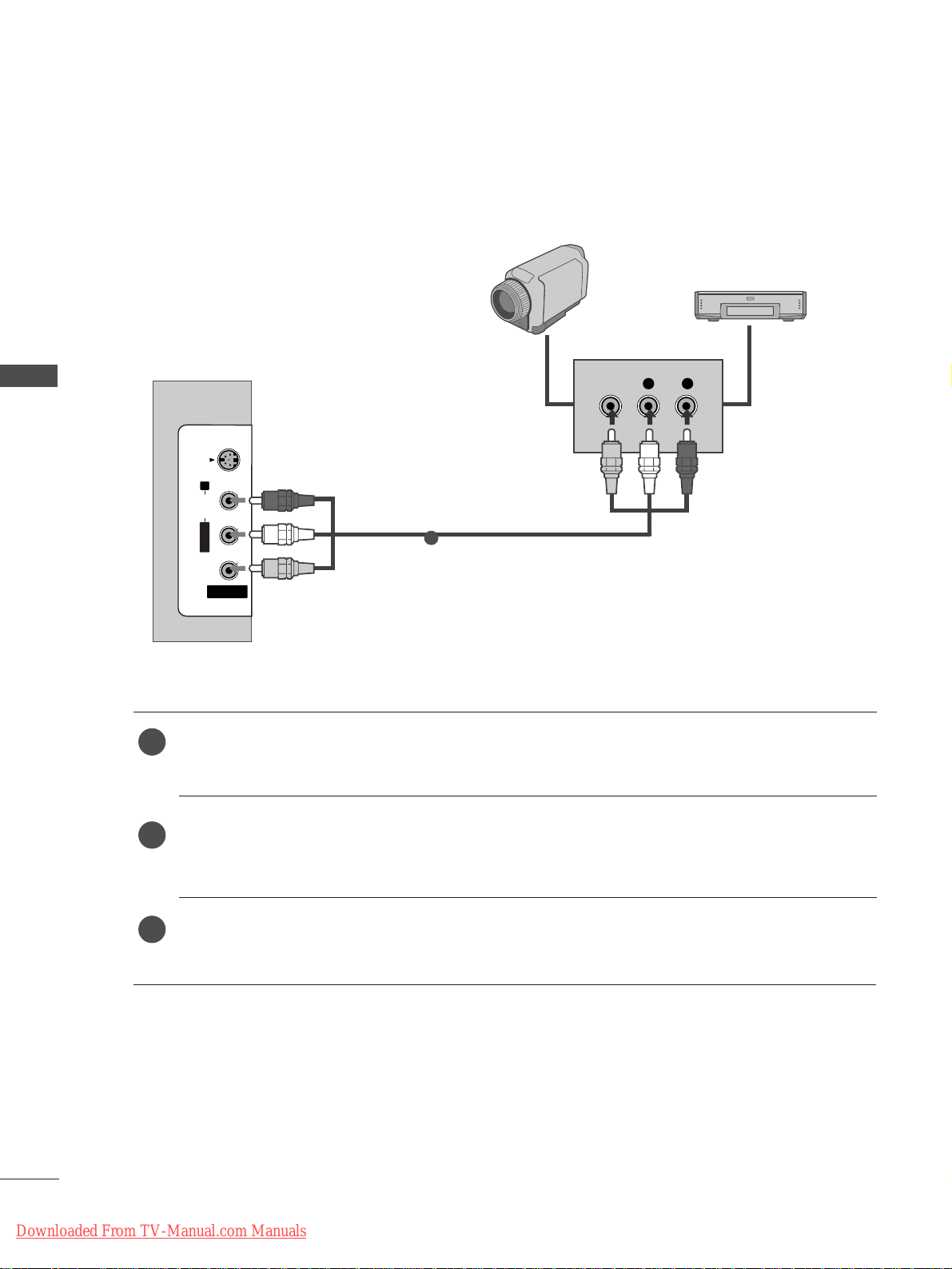
OTHER A/V SOURCE SETUP
Connect the
AAUU DDIIOO/VVIIDDEEOO
jacks between TV and external equipment. Match the jack colours
.
(
Video = yellow, Audio Left = white, and Audio Right = red
)
Select AV 2 input source using the
IINNPPUU TT
button on the remote control.
If connected to
AAVV IINN11
, select
AV 1 input source.
Operate the corresponding external equipment.
Refer to external equipment operating guide.
1
2
3
Downloaded From TV-Manual.com Manuals
Page 27
25
EXTERNAL EQUIPMENT SETUP
EXTERNAL STEREO
HDMI IN HDMI DVI IN
VARIABLEARIABLE
AUDIO OUTAUDIO OUT
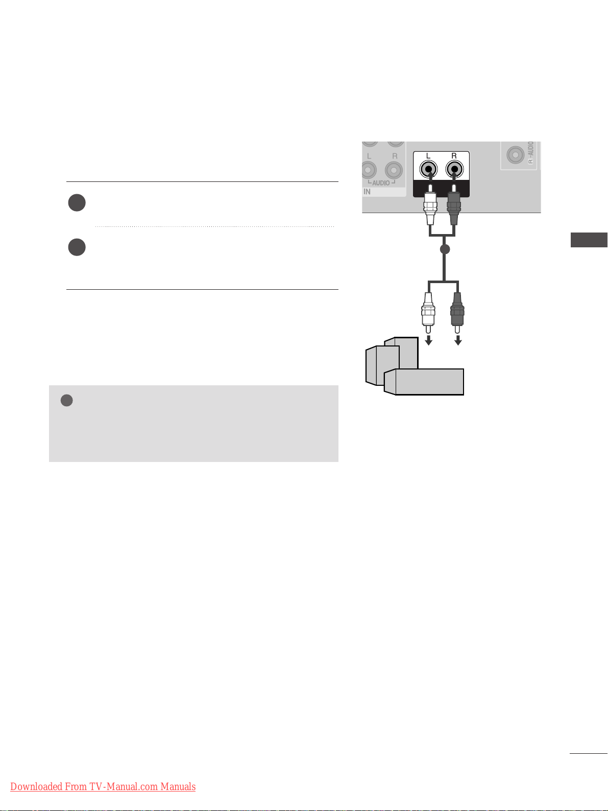
GG
When connecting with external audio equipments, such as
amplifiers or speakers, please turn the TV speakers off.
(
GG
pp..6655
)
NOTE
!
Use to connected either an external amplifier, or add a subwoofer to your surround sound system.
Connect the input jack of the stereo amplifier to the
VVAA RR IIAABBLL EE AAUUDD IIOO OO UUTT
jacks on the TV.
Set up your speakers through your analog stereo
amplifier, according to the instructions provided with
the amplifier.
2
1
11
Downloaded From TV-Manual.com Manuals
Page 28

AV IN 1AV IN 1 AV OUTAV OUT
AUDIO
(RGB/DVI)
RGB
(PC)
HDMI IN HDMI DVI IN
AUDIO
(RGB/DVI)
RGB
(PC)
RGB INRGB IN
L/MONO
RGB OUTPUT
AUDIO
1
2
26
PC SETUP
EXTERNAL EQUIPMENT SETUP
EXTERNAL EQUIPMENT SETUP
This TV provides Plug and Play capability, meaning that the PC adjusts automatically to the TV's settings.
Connecting with a D-sub 15 pin cable
Connect the RGB output of the PC to the
RRGG BB ((PP CC
))
jack on the TV.
Connect the PC audio output to the
AAUU DDIIOO
jack on the TV.
Turn on the PC and the TV.
Select
RGB PC input source using the
IINNPPUU TT
button on the remote control.
2
3
4
1
Downloaded From TV-Manual.com Manuals
Page 29

27
EXTERNAL EQUIPMENT SETUP
NOTE
!
GG
To enjoy vivid picture and sound, connect the PC
to the TV.
GG
Avoid keeping a fixed image on the TV ’s screen
for prolonged periods of time.The fixed image
may become permanently imprinted on the
screen;use a screen saver when possible.
GG
Connect the PC to the RGB (PC) port of the TV;
change the resolution output of PC accordingly.
GG
There may be interference relating to resolution,
vertical pattern, contrast or brightness in PC
mode. Change the PC mode to another resolution or change the refresh rate to another rate
or adjust the brightness and contrast on the
menu until the picture is clear. If the refresh rate
of the PC graphic card can not be changed,
change the PC graphic card or consult the manufacturer of the PC graphic card.
GG
The synchronization input waveform for
Horizontal and Vertical frequencies are separate.
GG
We recommend using 1366x768, 60Hz (LCD TV
models) / 852x480, 60Hz (42 inch WVGA
PLASMA TV models) / 1024x768, 60Hz (42
inch XGA PLASMA TV models) / 1360x768,
60Hz (50 inch PLASMA TV models) for the PC
mode, these should provide the best picture
quality.
GG
If the resolution of PC is over SXGA, there will
be no picture on the TV.
GG
Connect the audio cable from the PC to the
Audio input on the TV.(Audio cables are not
included with the TV).
GG
If you use too long an RGB-PC cable, there may
be interference on the screen. We recommend
using under 5m of the cable. This provides the
best picture quality.
Resolution
640x350
720x400
640x480
848x480
852x480
800x600
10 2 4x768
12 8 0x768
13 6 0x768
13 6 6x768
Supported Display Resolution (RGB-PC mode)
Horizontal Vertical
Frequency(kHz) Frequency(Hz)
31.5 70.1
31.5 70.1
31.5 59.9
31.5 60.0
31.5 60.0
37. 9 60.3
48.4 60.0
47. 8 59. 9
47. 7 59. 8
47. 7 59. 8
NOTE
!
GG
It’s supported to 848x480, 852x480 in VGA
modes. (VGA Models)
GG
It’s supported to 1280x768, 1360x768,
13 6 6x768 in XGA modes. (XGA Models)
Downloaded From TV-Manual.com Manuals
Page 30

28
EXTERNAL EQUIPMENT SETUP
EXTERNAL EQUIPMENT SETUP
Press the
MMEENN UU
button and then use
DD
//
EE
button to
select the
Picture menu.
Press the
GG
button and then use
DD
//
EE
button to select
Screen.
Press the
GG
button and then use
DD
//
EE
button to select
Auto Config..
Press the
GG
button to start Auto Config..
• When Auto config. has finished, OK will be shown on
screen.
• If the position of the image is still not correct, try Auto
adjustment again.
• If picture needs to be adjusted again after Auto adjust-
ment in RGB (PC), you can adjust the
Manual Config..
Press the
EEXXIITT
button to return to TV viewing.
Automatically adjusts picture position and minimizes image
instability. After adjustment, if the image is still not correct,
your TV is functioning properly but needs further adjustment.
AA uutt oo cc oo nnff ii gguurr ee
This function is for automatic adjustment of the screen position, clock, and phase. The displayed image will be unstable for
a few seconds while the auto configuration is in progress.
1
2
3
4
5
1
3 4
Screen Setup for PC mode
Auto Configure (RGB [PC] mode only)
Picture Mode
Colour Temperature
XD
Advanced
Aspect Ratio
Picture Reset
Screen
XD Demo
Picture
Screen
Auto config.
Manual Config.
VGA Mode
Reset
To Set
Auto Config. G
DE F G
OK MENU
2
Picture
Picture Mode
Colour Temperature
XD
Advanced
Aspect Ratio
Picture Reset
Screen
XD Demo
To Set
Screen G
DE F G
OK MENU
DE F G
OK MENU
OK
EXIT
VOL PR
SLEEP
LIST
Q.VIEW
MENU
123
456
789
FAV
MUTE
Downloaded From TV-Manual.com Manuals
Page 31

29
EXTERNAL EQUIPMENT SETUP
OK
EXIT
VOL PR
SLEEP
LIST
Q.VIEW
MENU
123
456
789
FAV
MUTE
If the picture is not clear after auto adjustment and especially if characters are still trembling, adjust the picture
phase manually.
To correct the screen size, adjust
CClloocckk
.
This function works in the following mode : RGB[PC], COMPONENT (480i/480p/576i/576p/720p/1080i), HDMI
(480p/576p/720p/1080i/1080p(except VGA Models)).
It’s not available to use Phase, Clock function in COMPONENT (480i/480p/576i/576p/720p/1080i), HDMI
(480p/576p/720p/1080i/1080p(except VGA Models)).
CClloocckk
This function is to minimize any vertical bars or
stripes visible on the screen background the horizontal screen size will also change.
PP hhaa ss ee
This function allows you to remove any horizontal
noise and clear or sharpen the image of characters.
Press the
MMEENN UU
button and then use
DD
//
EE
button to
select the
Picture menu.
Press the
GG
button and then use
DD
//
EE
button to select
Screen.
Press the
GG
button and then use
DD
//
EE
button to select
Manual Config..
Press the
GG
button and then use
DD
//
EE
button to select
Phase, Clock, H-Position or V-Position.
Press the
FF
//
GG
button to make appropriate adjustments.
Press the
EEXXIITT
button to return to TV viewing.
1
2
3
4
5
6
Adjustment for screen Phase, Clock, Position
1
3 4 5
Picture Mode
Colour Temperature
XD
Advanced
Aspect Ratio
Picture Reset
Screen
XD Demo
Picture
Screen
Auto Config.
Manual Config.
VGA Mode
Reset
Phase 50
Clock 0
H-Position 0
V-Position 0
Manual Config. G
DE F G
OK MENU
2
Picture
Picture Mode
Colour Temperature
XD
Advanced
Aspect Ratio
Picture Reset
Screen
XD Demo
To Set
Screen G
DE F G
OK MENU
DE F G
OK MENU
Downloaded From TV-Manual.com Manuals
Page 32

OK
EXIT
VOL PR
SLEEP
LIST
Q.VIEW
MENU
FAV
MUTE
30
EXTERNAL EQUIPMENT SETUP
1
3 4
Picture Mode
Colour Temperature
XD
Advanced
Aspect Ratio
Picture Reset
Screen
XD Demo
Picture
Screen
Auto Config.
Manual Config.
VGA Mode
Reset
640x480
848x480
852x480
VGA Mode G
DE F G
OK MENU
2
Picture
Picture Mode
Colour Temperature
XD
Advanced
Aspect Ratio
Picture Reset
Screen
XD Demo
To Set
Screen G
DE F G
OK MENU
To view a normal picture, match the resolution of RGB mode
and selection of VGA/XGA mode.
This function works in the following mode: RGB[PC] mode.
Press the
MMEENN UU
button and then use
DD
//
EE
button to
select the
Picture menu.
Press the
GG
button and then use
DD
//
EE
button to select
Screen.
Press the
GG
button and then use
DD
//
EE
button to select
VGA Mode (or XGA Mode).
Press the
GG
button and then use
DD
//
EE
button to select
the desired VGA/XGA resolution.
Press the
EEXXIITT
button to return to TV viewing.
Selecting Wide VGA/XGA mode
1
2
3
4
5
EXTERNAL EQUIPMENT SETUP
DE F G
OK MENU
Downloaded From TV-Manual.com Manuals
Page 33

OK
EXIT
VOL PR
SLEEP
LIST
Q.VIEW
MENU
123
456
789
FAV
MUTE
31
EXTERNAL EQUIPMENT SETUP
This function operates in current mode.
To initialize the adjusted value
Press the MENU button and then use
DD
//
EE
button to
select the
Picture menu.
Press the
GG
button and then use
DD
//
EE
button to select
Screen.
Press the
GG
button and then use
DD
//
EE
button to select
Reset.
Press the
GG
button.
• You can initialize Position, PIP size, PIP position.
Press the
EEXXIITT
button to return to normal TV viewing.
1
2
3
4
5
Initializing (Reset to original factory settings)
1
3 4
Picture Mode
Colour Temperature
XD
Advanced
Aspect Ratio
Picture Reset
Screen
XD Demo
Picture
Screen
Auto Config.
Manual Config.
VGA Mode
Reset
To Set
Reset G
DE F G
OK MENU
2
Picture
Picture Mode
Colour Temperature
XD
Advanced
Aspect Ratio
Picture Reset
Screen
XD Demo
To Set
Screen G
DE F G
OK MENU
Downloaded From TV-Manual.com Manuals
Page 34

OK
INPUT MODE
TVTV
DVD
RATIO
EXIT
VOL
POSITION
INDEX
PR
PIP
SLEEP
LIST
Q.VIEW
I/II
MENU
SIZE
VCR
PIP PR- PIP PR+
PIP INPUT
POWER
123
456
789
0
FAV
REVEAL
?
TEXT
SIMPLINK
INPUT
MUTE
TIME
HOLD
POWER
TV INPUT
INPUT
Switches the TV on from standby or off to standby.
Returns to the TV viewing from any mode.
Switches the TV on from standby.
If you press the button once, the input source OSD
will appear on screen as shown. Press the
DD/ EE
button and then OK button to select the desired input
source (TV, AV1, AV2, Component1, Component2, RGB
PC, HDMI1 or HDMI2).
RATIO
Brightness
adjustment
Selects your desired picture format.
Adjusts screen brightness.
This returns to the default settings brightness by chang-
ing mode source.
PIP
PIP PR - /+
PIP INPUT
SIZE
POSITION
Switches the sub picture PIP mode.
Selects a programme for the sub picture.
Selects the input source for the sub picture in PIP picture
mode.
Adjusts the sub picture size.
Moves the sub picture.
VCR/DVD
control buttons
Controls video cassette recorders or DVD players when
you select DVD or VCR mode button.
Control connected AV devices by pressing the
DD
//
EE
//
FF
//
GG
,
OO KK
buttons and buttons for play, stop, pause,
fast reverse, fast forward, chapter skip.
(The button does not provide such functions.)
EXIT
LIST
MENU
Q.VIEW
SLEEP
Clears all on-screen displays and returns to TV viewing
from any menu.
Displays the programme table.
Selects a menu.
Returns to the previously viewed programme.
Sets the sleep timer.
1
1
1
32
WATCHING TV / PROGRAMME CONTROL
WATCHING TV / PROGRAMME CONTROL
REMOTE CONTROL KEY FUNCTIONS
When using the remote control, aim it at the remote control sensor on the TV.
STB
or
Downloaded From TV-Manual.com Manuals
Page 35

Installing Batteries
■
Open the battery compartment cover on
the back and install the batteries matching
correct polarity (+with +,-with -).
■
Install two 1.5V AA batteries. Do not mix
old or used batteries with new ones.
■
Close cover.
OK
INPUT MODE
TVTV
DVD
RATIO
EXIT
VOL
POSITION
INDEX
PR
PIP
SLEEP
LIST
Q.VIEW
I/II
MENU
SIZE
VCR
PIP PR- PIP PR+
PIP INPUT
POWER
123
456
789
0
FAV
REVEAL
?
TEXT
SIMPLINK
INPUT
MUTE
TIME
HOLD
2
2
2
MODE
Selects the remote operating modes.
TELETEXT
BUTTONS
These buttons are used for teletext.
For further details, see the ‘Teletext’ section.
SIMPLINK
I/II
Coloured
buttons
See a list of AV devices connected to TV.
When you toggle this button, the Simplink menu appears
at the screen.(
GG
pp ..4444
)
Selects the sound output.
These buttons are used for teletext (on
TTEE LLEETTEEXXTT
mod-
els) or
PP rr oo gg rraammmmee eedd ii tt
.
THUMBSTICK
(Up/Down/Left
Right)
OK
Allows you to navigate the on-screen menus and adjust
the system settings to your preference.
Accepts your selection or displays the current mode.
VOLUME
UP/DOWN
FAV
MUTE
Programme
UP/DOWN
0~9 number
buttons
Adjusts the volume.
Displays the selected favourite programme.
Switches the sound on or off.
Selects a programme.
Selects a programme.
Selects numbered items in a menu.
33
WATCHING TV / PROGRAMME CONTROL
STB
or
Downloaded From TV-Manual.com Manuals
Page 36

34
WATCHING TV / PROGRAMME CONTROL
Press the
VVOO LL ++//--
button to adjust the volume.
If you wish to switch the sound off, press the
MMUUTTEE
button.
You can cancel the Mute function by pressing the
MMUUTTEE, VVOO LL ++//-- oorr
II//IIII
button.
PROGRAMME SELECTION
TURNING ON THE TV
WATCHING TV / PROGRAMME CONTROL
OK
INPUT MODE
TVTV
DVD
RATIO
EXIT
VOL
POSITION
INDEX
PR
PIP
SLEEP
LIST
Q.VIEW
I/II
MENU
SIZE
VCR
PIP PR- PIP PR+
PIP INPUT
POWER
123
456
789
0
FAV
REVEAL
?
TEXT
SIMPLINK
INPUT
MUTE
TIME
HOLD
When your TV is turned on, you will be able to use its features.
Firstly, connect the power cord correctly.
At this stage, the TV switches to standby mode.
■
In standby mode to turn TV on, press the ,
IINNPPUU TT,PP RR
DD
//
EE
button on the TV or press the
PP OOWWEE RR, TTVV, IINNPPUU TT, PP RR ++//--
,
NNUUMMBBEERR(( 00~99 ))
buttons on the remote control and the TV will switch
on.
1
VOLUME ADJUSTMENT
Press the
PP RR ++//--
or
NNUUMMBBEERR
buttons to select a programme number.
2
3
1
1
Downloaded From TV-Manual.com Manuals
Page 37

35
WATCHING TV / PROGRAMME CONTROL
ON SCREEN MENUS SELECTION AND ADJUSTMENT
Press the
MMEENN UU
button and then
DD/ EE
button to display each menu.
Press the
GG
button and then
DD/ EE
button to select a menu item.
Change the setting of an item in the sub or pull-down menu with
F / G button.
You can move to a higher level menu by pressing the
OO KK
or
MMEENN UU
button.
Your TV's OSD (On Screen Display) may differ slightly from that shown in this manual.
The OSD mainly use pictures for the Plasma TV models.
NOTE
!
a. The OSD (On Screen Display) function enables you to adjust the screen status conveniently since it pro-
vides graphical presentation.
b. In this manual, the OSD (On Screen Display) may be different from your TV’s because it is just example
to help the TV operation.
c. In the teletext mode, menus are not displayed.
Setup MENU
Picture MENU
Audio MENU
Time MENU
Option MENU
1
2
3
Language
SIMPLINK
Key Lock
ISM Method
Low Power
Option
Clock
Off Time
On Time
Sleep Time
Auto Sleep
Time
Picture Mode
Colour Temperature
XD
Advanced
Aspect Ratio
Picture Reset
Screen
XD Demo
Picture
Auto Tuning
Manual Tuning
Programme Edit
Favourite Programme
Setup
Sound Mode
Auto Volume
Balance 0
TV Speaker
Audio
* PLASMA TV models only
DE F G
OK MENU
DE F G
OK MENU
DE F G
OK MENU
DE F G
OK MENU
DE F G
OK MENU
Downloaded From TV-Manual.com Manuals
Page 38

OK
EXIT
VOL PR
SLEEP
LIST
Q.VIEW
MENU
FAV
Press the
MMEENNUU
button and then
DD
//
EE
button to select the
Setup menu.
Press the
GG
button and then
DD
//
EE
button to select Auto
Tuning.
Press the
GG
button and then
DD
//
EE
button to select System.
Press the
DD
//
EE
button to select a TV system menu;
BG: PAL B/G, SECAM B/G (Europe / East Europe / Asia /
NewZealand / M.East / Africa / Australia)
I: PAL I/II (U.K. / Ireland / Hong Kong / South Africa)
DK: PAL D/K, SECAM D/K (East Europe / China / Africa / CIS)
M: (USA / Korea / Philippines)
Press the
DD
//
EE
button to select Storage From.
Press the
FF
//
GG
button or NUMBER buttons to select the ini-
tial programme number. If you use NUMBER buttons, any
number under 10 is entered with a numeric ‘0’ in front of it,
i.e.‘
00 55
’ for 5.
Press the
DD
//
EE
button to select Search.
Press the
GG
button to begin auto tuning.
All receivable stations are stored.
To stop auto tuning, press the
MMEENNUU
button.
When auto tuning is complete, the Programme edit menu
appears on the screen. See the Programme edit section to edit
the stored programme.
Press the
EEXXIITT
button to return to normal TV viewing.
1
2
3
4
5
6
7
8
9
Up to 100 TV stations can be stored by programme numbers (0 to 99).
Once you have preset the stations, you will be able to use the PR +/- or
NUMBER buttons to scan the stations you have programmed.
Stations can be tuned using automatic or manual modes.
All stations which can be received are stored by this method. It is recommended that you use Auto tuning during installation of this TV.
36
WATCHING TV / PROGRAMME CONTROL
WATCHING TV / PROGRAMME CONTROL
AUTO PROGRAMME TUNING
1
Auto Tuning
Manual Tuning
Programme Edit
Favourite Programme
Setup
Auto Tuning
System
Storage From
Search
System G
DE F G
OK MENU
2
Setup
Auto Tuning
Manual Tuning
Programme Edit
Favourite Programme
To Set
Auto Tuning G
DE F G
OK MENU
3 4 5 6
7
8
Auto Tuning
C 05 BG
5 35%
MENU Stop
BG
I
DK
M
DE F G
OK MENU
Downloaded From TV-Manual.com Manuals
Page 39

OK
EXIT
VOL PR
SLEEP
LIST
Q.VIEW
MENU
123
456
789
0
FAV
MUTE
TIME
HOLD
37
WATCHING TV / PROGRAMME CONTROL
MANUAL PROGRAMME TUNING
Press the
MM EENNUU
button and then
DD
//
EE
button to select the
Setup menu.
Press the GGbutton and then
DD
//
EE
button to select Manual
Tuning
.
Press theGGbutton and then
DD
//
EE
button to select Storage.
Press the
FF
//
GG
button or NUMBER buttons to select the
desired programme number (0 to 99). If you use NUMBER
buttons, any number under 10 is entered with a numeric ‘0’ in
front of it, i.e. ‘
0055
’ for 5.
Press the
DD
//
EE
button to select System.
Press the
DD
//
EE
button to select a TV system menu;
BG : PAL B/G, SECAM B/G (Europe / East Europe / Asia /
NewZealand / M.East / Africa / Australia)
I: PAL I/II (U.K. / Ireland / Hong Kong / South Africa)
DK : PAL D/K, SECAM D/K (East Europe / China / Africa / CIS)
M: (USA / Korea / Philippines)
Press the
DD
//
EE
button to select Band.
Press theGGbutton and then
DD
//
EE
button to select V/UHF
or Cable.
Press the
DD
//
EE
button to select Channel.
You can select the desired programme number with the
FF
//
GG
button or NUMBER buttons. If possible, select the programme
number directly with the number buttons. Any number under
10 is entered with a numeric ‘0’ in front of it, i.e. ‘
0055
’ for 5.
Press the
DD
//
EE
button to select Search.
Press the
FF
//
GG
button to commence searching. If a station is
found the search will stop.
Press the
OO KK
button to store it.
To store another station, repeat steps 33to
1133
.
Press the
EEXXIITT
button to return to normal TV viewing.
Manual programme lets you manually tune and arrange the stations in whatever order you desire.
1
2
3
4
5
6
7
8
9
10
11
12
13
14
15
1
Auto Tuning
Manual Tuning
Programme Edit
Favourite Programme
Setup
Manual Tuning
Storage
System
Band
Channel
Fine
Search
Name
Storage G
DE F G
OK MENU
2
Setup
Auto Tuning
Manual Tuning
Programme Edit
Favourite Programme
To Set
Manual Tuning G
DE F G
OK MENU
99
73 4 5 6
8 9
10 11 12
DE F G
OK MENU
Downloaded From TV-Manual.com Manuals
Page 40

OK
EXIT
VOL PR
SLEEP
LIST
Q.VIEW
MENU
123
456
789
FAV
MUTE
38
WATCHING TV / PROGRAMME CONTROL
WATCHING TV / PROGRAMME CONTROL
FINE TUNING
Press the
MMEENN UU
button and then
DD
//
EE
button to select
the
Setup menu.
Press the
GG
button and then
DD
//
EE
button to select
Manual Tuning.
Press the
GG
button and then
DD
//
EE
button to select Fine.
Press the
GG
button and then
FF
//
GG
button to fine tune for
the best picture and sound.
Press the
OO KK
button to store it.
Press the
EEXXIITT
button to return to normal TV viewing.
1
2
3
4
5
6
Normally fine tuning is only necessary if reception is poor.
1
Auto Tuning
Manual Tuning
Programme Edit
Favourite Programme
Setup
Manual Tuning
Storage
System
Band
Channel
Fine
Search
Name
Fine G
DE F G
OK MENU
2
Setup
Auto Tuning
Manual Tuning
Programme Edit
Favourite Programme
To Set
Manual Tuning G
DE F G
OK MENU
F/G
3 4 5
DE F G
OK MENU
Downloaded From TV-Manual.com Manuals
Page 41

OK
EXIT
VOL PR
SLEEP
LIST
Q.VIEW
MENU
123
456
789
FAV
MUTE
39
WATCHING TV / PROGRAMME CONTROL
ASSIGNING A STATION NAME
You can assign a station name up to five characters to each programme number.
Press the
MMEENN UU
button and then
DD
//
EE
button to select
the
Setup menu.
Press the
GG
button and then
DD
//
EE
button to select
Manual Tuning.
Press the
GG
button and then
DD
//
EE
button to select
Name.
Press the
GG
button and then
DD//EE
button. You can use a
blank, ++, --, the number
0 to 9 and the alphabet A to Z.
Press the
FF
//
GG
button to select the position and make
your choice of the second character, and so on.
Press the
OO KK
button to store it.
Press the
EEXXIITT
button to return to normal TV viewing.
1
2
3
4
5
6
7
3 4 5 6
1
Auto Tuning
Manual Tuning
Programme Edit
Favourite Programme
Setup
Manual Tuning
Storage
System
Band
Channel
Fine
Search
Name
Name G
DE F G
OK MENU
2
Setup
Auto Tuning
Manual Tuning
Programme Edit
Favourite Programme
To Set
Manual Tuning G
DE F G
OK MENU
C 05
DE F G
OK MENU
Downloaded From TV-Manual.com Manuals
Page 42

OK
EXIT
VOL PR
SLEEP
LIST
Q.VIEW
MENU
123
456
789
FAV
MUTE
40
WATCHING TV / PROGRAMME CONTROL
PROGRAMME EDIT
WATCHING TV / PROGRAMME CONTROL
This function enables you to delete or skip stored programmes.
Also you can move some stations to other programme numbers
or copy a blank station data into the selected programme number.
Press the
MMEENN UU
button and then
DD
//
EE
button to select
the
Setup menu.
Press the
GG
button and then
DD
//
EE
button to select
Programme Edit.
Press the GGbutton to display the
Programme edit menu.
AA
DDeelleettiinngg aa pprrooggrraammmmee
1.Select a programme to be deleted with the
DD
// EE//
FF
//
GG
button.
2.Press the RED button twice.
The selected programme is deleted, all the following
programmes are shifted up one position.
AA
CCooppyyiinngg aa pprrooggrraammmmee
1.Select a programme to be copied with the
DD
// EE//
FF
//
GG
button.
2.Press the GREEN button.
All the following programmes are shifted down one position.
AA
MMoovviinngg aa pprrooggrraammmmee
1.Select a programme to be moved with the
DD
// EE//
FF
//
GG
button.
2.Press the YELLOW button.
3.Move the programme to the desired programme number with
the
DD
// EE//
FF
//
GG
button.
4.Press the YELLOW button again to release this function.
AA
SSkkiippppiinngg aa pprrooggrraammmmee nnuummbbeerr
1.Select a programme number to be skipped with the
DD
// EE//
FF
//
GG
button.
2.Press the BLUE button. The skipped programme turns to blue.
3.Press the BLUE button again to release the skipped programme.
When a programme number is skipped it means that you will
be unable to select it using the
DD
//
EE
button during normal
TV viewing. If you wish to select the skipped programme,
directly enter the programme number with the NUMBER buttons or select it in the programme edit or table menu.
Press the
EEXXIITT
button to return to normal TV viewing.
1
2
3
4
3
Programme Edit
DE F G
OK MENU
Delete
Move
Copy
Skip
1
Auto Tuning
Manual Tuning
Programme Edit
Favourite Programme
Setup
2
Setup
Auto Tuning
Manual Tuning
Programme Edit
Favourite Programme
To Set
Programme Edit G
DE F G
OK MENU
DE F G
OK MENU
0C03 5S69
1BLN03 6S17
2C12 7S22
3S66 8C09
4S67 9C11
Downloaded From TV-Manual.com Manuals
Page 43

OK
EXIT
VOL PR
SLEEP
LIST
Q.VIEW
MENU
123
456
789
0
FAV
MUTE
TIME
HOLD
41
WATCHING TV / PROGRAMME CONTROL
FAVOURITE PROGRAMME
Press the
MMEENNUU
button and then
DD
//
EE
button to select the
Setup menu.
Press the
GG
button and then
DD
//
EE
button to select
Favourite Programme.
Press the
GG
button.
Press the
DD
//
EE
button to select - - - - - - -.
Select a desired programme with the
FF
//
GG
button or NUMBER buttons. Any number under 10 is entered with a numeric
‘0’in front of it, i.e.‘
00 55
’ for 5.
To store another programme, repeat steps
4 to 5.
You can store up to 8 programmes.
Press the
EEXXIITT
button to return to normal TV viewing.
This function lets you select your favourite programmes directly.
Repeatedly press the FAV button to select stored favourite programmes.
1
2
3
4
5
6
7
1
Auto Tuning
Manual Tuning
Programme Edit
Favourite Programme
Setup
Setup
Auto Tuning
Manual Tuning
Programme Edit
Favourite Programme
Favourite Programme G
DE F G
OK MENU
-- -----
-- -----
-- -----
-- -----
-- -----
-- -----
-- -----
-- -----
2 3 4 5
DE F G
OK MENU
Downloaded From TV-Manual.com Manuals
Page 44

OK
EXIT
VOL PR
SLEEP
LIST
Q.VIEW
MENU
123
456
789
FAV
MUTE
42
WATCHING TV / PROGRAMME CONTROL
SELECTING THE PROGRAMME TABLE
WATCHING TV / PROGRAMME CONTROL
You can check which programmes are stored in the memory by displaying the programme table.
AA
DDiiss ppllaayyiinngg pprroo ggrraa mmmm ee ttaabbllee
Press the
LLIISSTT
button to display the Programme table menu.
The programme table appears on the screen.
One programme table contains ten programmes as shown.
AA
SSeellee cc ttii nngg aa pprroo gg rr aammmmee iinn tthhee pprroo gg rraamm mmee ttaabb ll ee
Select a programme with the
DD
//
EE
//
FF
//
GG
button.
Then press the
OO KK
button. The TV switches to the chosen
programme number.
AA
PPaaggii nn gg tt hh rr oouugghh aa pprroogg rr aamm mmee ttaabb llee
There are 10 programme table pages in which contain 100 pro
grammes. Pressing the
DD
//
EE
//
FF
//
GG
button repeatedly turns the
pages.
Press the
LL II SSTT
button to return to normal TV viewing.
NOTE
!
a. You may find some blue programmes. They have been set up
to be skipped by auto programming or in the programme edit
mode.
b. Some programmes with the channel number shown in the
programme table indicate there is no station name assigned.
Programme List
FG DE
OK
0C03 5S69
1BLN03 6S17
2C12 7S22
3S66 8C09
4S67 9C11
Downloaded From TV-Manual.com Manuals
Page 45

OK
EXIT
VOL PR
SLEEP
LIST
Q.VIEW
MENU
123
456
789
FAV
MUTE
43
WATCHING TV / PROGRAMME CONTROL
KEY LOCK
NOTE
!
GG
In
KK eeyy LLoo cc kk ‘OOnn
’, if the TV is turned off, press the
rr // II,IINN PPUUTT, PP RR DD//
EE
button on the TV or
PP OOWWEERR, IINN PPUUTT, TT VV, PP RR
++ //--
or NUMBER buttons on the remote control.
GG
With the
KK eeyy LLoo cc kk OO nn
, the display ‘
Key Lock On
’ appears on the screen if any button on the front
panel is pressed while viewing the TV.
The TV can be set so that the remote control is needed to control it.
This feature can be used to prevent unauthorized viewing.
This TV is programmed to remember which option it was last
set to even if you turn the TV off.
Press the
MMEENN UU
button and then
DD
//
EE
button to select
the
Option
menu.
Press the
GG
button and then
DD
//
EE
button to select Key
Lock.
Press the
GG
button and then
DD
//
EE
button to select On or
Off.
Press the
EEXXIITT
button to return to normal TV viewing.
1
2
3
4
1
Language
SIMPLINK
Key Lock
ISM Method
Low Power
Option
32
Option
Language
SIMPLINK
Key Lock
ISM Method
Low Power
Key Lock G
DE F G
OK MENU
Off
On
DE F G
OK MENU
Downloaded From TV-Manual.com Manuals
Page 46

44
WATCHING TV / PROGRAMME CONTROL
WATCHING TV / PROGRAMME CONTROL
OK
INPUT MODE
TVTV
DVD
RATIO
EXIT
PIP
SLEEP
LIST
Q.VIEW
I/II
MENU
VCR
PIP PR- PIP PR+
PIP INPUT
POWER
TEXT
SIMPLINK
INPUT
32
Option
Language
SIMPLINK
Key Lock
ISM Method
Low Power
SIMPLINK G
DE F G
OK MENU
Off
On
1
Language
SIMPLINK
Key Lock
ISM Method
Low Power
Option
DE F G
OK MENU
This fundtion operates only with devices with the SIMPLINK logo.
Please check the SIMPLINK logo.
This allows you to control and play other AV devices connected to
the display through HDMI cable without additional cables and settings.
If you do not require the SIMPLINK menu, select “Off”.
Press the
MMEENN UU
button and then
DD
//
EE
button to select the
Option
menu.
Press the
GG
button and then
DD
//
EE
button to select
SIM-
PLINK
.
Press the
GG
button and then
DD
//
EE
button to select
On
or
Off
.
Press the
EEXX IITT
button to return to normal TV viewing.
1
2
3
4
Downloaded From TV-Manual.com Manuals
Page 47

45
WATCHING TV / PROGRAMME CONTROL
DE
OK
TV
DISC
F
DVD HTS
G
VCR
HDD Recorder
SPEAKER
F
TV Speaker
G
NOTE
!
GG
Connect the HDMI/DVI IN or HDMI IN terminal of the TV to the rear terminal (HDMI terminal) of the
SIMPLINK device with the HDMI cable.
GG
After connecting the HDMI terminal for the home theatre with SIMPLINK function using the above
method, connect the VARIABLE AUDIO OUT terminal on the back of the TV to the VARIABLE AUDIO IN
terminal on the back of the SIMPLINK device with the VARIABLE AUDIO OUT cable.
GG
When operating an external device with SIMPLINK, press the TV button from the MODE button on the
remote control.
GG
When you switch the Input source using the INPUT button on the remote control, you can stop the
operation of a device controlled by SIMPLINK.
GG
When you select or operate a media device with home theatre function, the speaker automatically
switches to home theatre speaker (HT speaker).
DDiisscc ppllaa yybbaacckk
Control connected AV devices by pressing the
DD
//
EE
//
FF
//
GG
,
OO KK
buttons and buttons for play, stop, pause, fast
reverse, fast forward, chapter skip.(The button does not provide such functions)
DDiirreecctt PPllaayy
After connecting AV devices to the TV, you can directly control the devices and play media without additional settings.
SSeelleecctt AAVV ddeevviiccee
Enables you to select one of the AV devices connected to the TV and operate it.
PPoowweerr ooffff aallll ddeevviicceess
When you switch off the TV, all connected devices are turned off.
SSwwiittcchh aauudd iioo--oouutt
Offers an easy way to switch audio-out.
** AA ddeevviiccee,, wwhhiicc hh iiss cc oonnnn ee cctt ee dd ttoo tthhee TTVV tt hhrr oouugghh aa HHDDMMII ccaabbllee bbuutt dd ooee ss nnoott ssuu ppppoorr tt SS IIMMPP LLIINN KK,, ddooeess nn oo tt
pprr oo vviidd ee tthh ii ss ffuunncctt iioo nn..
SIMPLINK Functions
TTVV vv ii eewwiinngg ::
Switch to the previous TV programme
regardless of the current mode.
DD IISSCC ppll aayybbaa cckk ::
Select and play discs. When multiple
discs are available, the titles of the discs are conveniently displayed at the bottom of the screen.
VVCCRR ppll aayybbaa cckk ::
Control the connected VCR.
HH DDDD RReeccoo rr ddiinn gg ss ppllaayybb aacc kk ::
Control recordings
stored in HDD.
AAuuddiioo OOuu tt ttoo HHoommee tthh ee aatteerr//AAuu ddiioo OOuu tt ttoo TTVV ::
Select Home theater or TV speaker for Audio Out.
Selected Device
When no device is connected (displayed in gray)
When a device is
connected (displayed in
bright colour)
1
2
3
4
5
1
2
3
4
5
SIMPLINK Menu
Press the
DD/ EE
/FF/
GG
button and then OK button to select the desired SIMPLINK source.
Downloaded From TV-Manual.com Manuals
Page 48

PICTURE CONTROL
46
WATCHING PIP(PICTURE-IN-PICTURE)
PICTURE CONTROL
PIP lets you view 2 different inputs (sources) on your TV screen at the same time.
One source will be large, and the other source will show a smaller inset image.
PIP function is available in the Component, RGB, HDMI mode. (But, it can’t adjust
480i/576i resolution of Component mode.)
Programme Selection for Sub Picture
Press the PIP PR +/- button to select a programme for the sub picture.
The selected programme number is displayed just below the programme number of main picture.
Watching PIP/Double Window
Press the
PP IIPP
button to access the sub picture.
Each press of PIP changes the PIP options.
PIP Mode
DW Mode
PIP Off
INPUT MODE
POWER
INPUT
RATIO
SIMPLINK
PIP
PIP PR- PIP PR+
LIST
EXIT
VOL
123
456
789
TIME
SIZE
?
REVEAL
TEXT
MENU
OK
FAV
MUTE
0
POSITION
TVTV
DVD
VCR
I/II
PIP INPUT
Q.VIEW
SLEEP
PR
HOLD
INDEX
Downloaded From TV-Manual.com Manuals
Page 49

PICTURE CONTROL
47
Sub Picture Size Adjustment (PIP mode only)
Press the
SS II ZZEE
button to adjust the sub picture size.
With
SS II ZZEE
button in PIP mode, sub picture is adjusted.
Moving the Sub Picture (PIP mode only)
Press the
PP OOSS IITTIIOONN
button.
Repeatedly press the
PP OOSS II TT IIOONN
button then sub picture moves.
Input Source Selection for Sub Picture
Press the
PP IIPP IINNPPUU TT
button to select the input source for the sub picture.
Each press of
PP IIPP IINNPPUU TT
button is pressed, each input source for the sub picture is displayed.
(Sub picture can be selected only TV, AV1, AV2)
Downloaded From TV-Manual.com Manuals
Page 50

PICTURE CONTROL
48
PICTURE SIZE (ASPECT RATIO)CONTROL
PICTURE CONTROL
OK
INPUT MODE
TVTV
DVD
RATIO
EXIT
VOL PR
PIP
SLEEP
LIST
Q.VIEW
I/II
MENU
VCR
PIP PR- PIP PR+
PIP INPUT
POWER
FAV
TEXT
SIMPLINK
INPUT
MUTE
You can watch the screen in various picture formats;
SS ppee ccttaa ccll ee
,
OOrriiggiinn aa ll, 44 :: 33
,
11 66::99, 11 44::99
and
ZZoo oo mm11//22
.
If a fixed image is displayed on the screen for a long time, that fixed image may
become imprinted on the screen and remain visible.
You can adjust the enlarge proportion using
DD
//
EE
button.
This function works in the following signal.
•
SSppeeccttaaccllee
When your TV receives the wide screen signal, when
selected it will adjust the picture horizontally, in non-linear proportion, to fill the entire screen.
•
OOrriiggiinnaall
When your TV receives a wide screen signal it will automatically change to the picture format to be broadcast.
•
44::33
The following selection will allow you to view a picture
with an original 4:3 aspect ration, grey bars will appear
on both the left and right hand of the screen.
•
1166::99
The following selection will allow you to adjust the picture horizontally, in linear proportion, to fill the entire
screen(useful for viewing 4:3 formatted DVDs).
Press the
RRAATTIIOO
button repeatedly to select the desired picture format.
You can also adjust
AAssppeecctt RRaattiioo
in the
Picture menu.
1
Spectacle
DE
4:3
16:9
Original
Downloaded From TV-Manual.com Manuals
Page 51

•
1144::99
You can view a picture format of 14:9 or a general TV
programme in the 14:9 mode. The 14:9 screen is
viewed in the same way as in 4:3, but is magnified to
the left and right.
•
ZZ oooomm11
The following selection will allow you to view
the picture without any alteration, while filling
the entire screen. However, the top and bottom of the picture will be cropped.
•
ZZ oooomm22
Choose Zoom 2 when you wish the picture to
be altered, both horizontally extended and
vertically cropped. The picture adopting a
compromise between alteration and screen
converage.
PICTURE CONTROL
49
NOTE
!
GG
You can only select
44 :: 33, 11 66::99
(Wide) in Component, RGB, HDMI mode only.
14:9
DE
Zooml
DE
Zoom2
DE
Downloaded From TV-Manual.com Manuals
Page 52

PICTURE CONTROL
50
PICTURE CONTROL
OK
EXIT
VOL PR
SLEEP
LIST
Q.VIEW
MENU
123
456
789
FAV
MUTE
PRESET PICTURE SETTINGS
CCaabb ll ee
Select this option to optimize the image
about the external video device. (It’s not
available for all models.)
IInntt ee ll ll ii ggeenntt EEyyee
Adjusts picture according to the surrounding conditions.
(32/42LB9R* only)
DDyy nnaammiicc
Select this option to display a sharp image.
SSttaann ddaarr dd
The most general and natural screen display status.
MMiilldd
Select this option to display a mild image.
UU ss ee rr 11//22
Selection this option to use a user defined setting.
Press the
MMEENN UU
button and then
DD
//
EE
button to select
the
Picture menu.
Press the
GG
button and then
DD
//
EE
button to select
Picture Mode.
Press the
GG
button and then
DD
//
EE
button to select Cable
(
It’s not available for all models.)
, Intelligent Eye
(32/42LB9R* only), Dynamic, Standard, Mild, User1 or
User2.
Press the
EEXXIITT
button to return to normal TV viewing.
• Picture Mode adjusts the TV for the best picture appearance. Select the preset value in the
PP ii ccttuurree MMoodd ee
menu
based on the programme category.
• Cable (It’s not available for all models.), Intelligent Eye
(32/42LB9R* only), Dynamic, Standard and Mild are pro-
grammed for optimum picture reproduction at the factory and
cannot be changed.
• When the Intelligent eye function is on, the most suitable
picture is automatically adjusted according to the surrounding conditions.
(32/42LB9R* only)
Picture Mode-Preset
1
2
3
4
1
Picture Mode
Colour Temperature
XD
Advanced
Aspect Ratio
Picture Reset
Screen
XD Demo
Picture
32
Picture
Picture Mode
Colour Temperature
XD
Advanced
Aspect Ratio
Picture Reset
Screen
XD Demo
Picture Mode G
DE F G
OK MENU
Cable
Intelligent Eye
Dynamic
Standard
Mild
User1
User2
DE F G
OK MENU
NOTE
!
GG
Cable is available to use this function in AV mode.
GG
Cable
is not available for all models.
Downloaded From TV-Manual.com Manuals
Page 53

OK
EXIT
VOL PR
SLEEP
LIST
Q.VIEW
MENU
123
456
789
FAV
MUTE
PICTURE CONTROL
51
To initialize values (reset to default settings), select the Cool
option.
Choose one of three automatic colour adjustments. Set to
warm to enhance hotter colours such as red, or set to cool to
see less intense colours with more blue.
This menu is activated after selecting “User1” or “User2” in the
Picture Mode.
Press the
MMEENN UU
button and then
DD
//
EE
button to select
the
Picture menu.
Press the
GG
button and then
DD
//
EE
button to select
Colour Temperature.
Press the
GG
button and then
DD
//
EE
button to select
either
Cool, Medium, Wa r m or User.
Press the
EEXXIITT
button to return to normal TV viewing.
1
2
3
4
Auto Colour Tone Control(Warm/Medium/Cool)
1
Picture Mode
Colour Temperature
XD
Advanced
Aspect Ratio
Picture Reset
Screen
XD Demo
Picture
32
Picture
Picture Mode
Colour Temperature
XD
Advanced
Aspect Ratio
Picture Reset
Screen
XD Demo
Colour Temperature G
DE F G
OK MENU
Cool
Medium
Warm
User
DE F G
OK MENU
Downloaded From TV-Manual.com Manuals
Page 54

OK
EXIT
VOL PR
SLEEP
LIST
Q.VIEW
MENU
123
FAV
MUTE
PICTURE CONTROL
52
MANUAL PICTURE ADJUSTMENT
PICTURE CONTROL
Press the
MMEENN UU
button and then
DD
//
EE
button to select
the
Picture menu.
Press the
GG
button and then
DD
//
EE
button to select
Picture Mode.
Press the
GG
button and then
DD
//
EE
button to select User1
or User2.
Press the
GG
button and then
DD
//
EE
button to select the
desired picture option (
Contrast, Brightness, Colour,
Sharpness and Tint).
Press the
FF
//
GG
button to make appropriate adjustments.
Press the
EEXXIITT
button to return to normal TV viewing.
Picture Mode-User Option
CCoonn ttrraasstt
Adjusts the difference between light and dark
levels in the picture.
BBrriigghh ttnneessss
Increases or decreases the amount of white in
the picture.
CCoolloouurr
Adjusts intensity of all colours.
SShhaarr ppnn ee ss ss
Adjusts the level of crispness in the edges
between the light and dark areas of the picture.
The lower the level, the softer the image.
TT iinn tt
Adjusts the balance between red and green levels.
NOTE
!
GG
You cannot adjust colour, sharpness and tint in the
RGB-PC mode.
1
2
3
4
5
6
1
Picture Mode
Colour Temperature
XD
Advanced
Aspect Ratio
Picture Reset
Screen
XD Demo
Picture
32
Picture
Picture Mode
Colour Temperature
XD
Advanced
Aspect Ratio
Picture Reset
Screen
XD Demo
Picture Mode G
DE F G
OK MENU
Cable
Intelligent Eye
Dynamic
Standard
Mild
User1
User2
54
User1
Contrast 100
Brightness 50
Colour 50
Sharpness 50
Tint 0
Contrast 100 G
DE F G
OK MENU
Contrast 100 F
G
E
DE F G
OK MENU
Downloaded From TV-Manual.com Manuals
Page 55

OK
EXIT
VOL PR
SLEEP
LIST
Q.VIEW
MENU
123
FAV
MUTE
PICTURE CONTROL
53
To adjust red, green, blue to any colour temperature you prefer.
This menu is activated after selecting “User1” or “User2” in the
Picture Mode.
Colour Tone - User Option
Press the
MMEENN UU
button and then
DD
//
EE
button to select
the
Picture menu.
Press the
GG
button and then
DD
//
EE
button to select
Colour Temperature.
Press the
GG
button and then
DD
//
EE
button to select User.
Press the
GG
button and then
DD
//
EE
button to select Red,
Green or Blue.
Press the
FF
//
GG
button to make appropriate adjustments.
Press the
EEXXIITT
button to return to normal TV viewing.
1
2
3
4
5
6
1
Picture Mode
Colour Temperature
XD
Advanced
Aspect Ratio
Picture Reset
Screen
XD Demo
Picture
32
Picture
Picture Mode
Colour Temperature
XD
Advanced
Aspect Ratio
Picture Reset
Screen
XD Demo
Colour Temperature G
DE F G
OK MENU
Cool
Medium
Warm
User
54
Red +30
Green 0
Blue 0
Red +30 G
DE F G
OK MENU
User
Red +30 F
G
E
DE F G
OK MENU
Downloaded From TV-Manual.com Manuals
Page 56

OK
EXIT
VOL PR
SLEEP
LIST
Q.VIEW
MENU
123
456
789
FAV
MUTE
PICTURE CONTROL
54
- PICTURE IMPROVEMENT TECHNOLOGY
PICTURE CONTROL
Press the MENU button and then
DD
//
EE
button to select
the
Picture menu.
Press the
GG
button and then
DD
//
EE
button to select XD.
Press the
GG
button and then
DD
//
EE
button to select
Auto or Manual.
Press the
EEXXIITT
button to return to TV viewing.
* Manual Selection
This menu is activated after selecting the
User1
or
User2
of
PPiiccttuurree
MM ooddee
.
Press theGGbutton and then
DD
//
EE
button to select
XX DD
Contrast, XD Colour or XD NR.
Press the
GG
button and then
DD
//
EE
button to select On or
Off.
Press the
EEXXIITT
button to return to normal TV viewing.
XD is LG electronic's unique picture improving technology to
display a real HD source through an advanced digital signal processing algorithm.
It is not possible to use this function in RGB-PC mode.
AA
XXDD CCoonnttrraasstt ::
Optimises the contract automatically
according to the brightness of the reflection.
AA
XXDD CCooll oouu rr ::
Adjusts the colour of the reflection automatically to reproduce as close as possible to natural
colours.
AA
XXDD NN RR
: Removes interference up to the point where it
does not damage the original picture. (It is not possible
to use this function in HDMI, Component (except
480i/576i), RGB-PC mode.)
1
2
3
4
1
2
3
1
Picture Mode
Colour Temperature
XD
Advanced
Aspect Ratio
Picture Reset
Screen
XD Demo
Picture
32
Picture
Picture Mode
Colour Temperature
XD
Advanced
Aspect Ratio
Picture Reset
Screen
XD Demo
XD G
DE F G
OK MENU
Auto
Manual
Manual
XD Contrast G
XD Colour
XD NR
XD Contrast G
DE F G
OK MENU
Off
On
21
DE F G
OK MENU
Downloaded From TV-Manual.com Manuals
Page 57

OK
EXIT
VOL PR
SLEEP
LIST
Q.VIEW
MENU
123
FAV
MUTE
PICTURE CONTROL
55
DEMO
Use it to see the difference between XD Demo on and XD
Demo off.
It is not possible to use this function in RGB[PC] mode.
Press the MENU button and then
DD
//
EE
button to select
the
Picture menu.
Press the
GG
button and then
DD
//
EE
button to select XD Demo.
Press the GGbutton to begin XD Demo.
To s top
XXDD DD eemmoo
, press the
MMEENN UU
button.
1
2
3
4
• XD Demo
XD™Off XD™ On
MENU Exit
1
Picture Mode
Colour Temperature
XD
Advanced
Aspect Ratio
Picture Reset
Screen
XD Demo
Picture
32
Picture
Picture Mode
Colour Temperature
XD
Advanced
Aspect Ratio
Picture Reset
Screen
XD Demo
XD Demo G
DE F G
OK MENU
To Start
DE F G
OK MENU
Downloaded From TV-Manual.com Manuals
Page 58

OK
EXIT
VOL PR
SLEEP
LIST
Q.VIEW
MENU
123
456
FAV
MUTE
PICTURE CONTROL
56
ADVANCED - CINEMA
PICTURE CONTROL
To set the TV up for the best picture quality for viewing
films.
This feature operates only in Analog TV, AV, S-video and
Component 480i/576i mode.
Press the
MMEENN UU
button and then
DD
//
EE
button to select
the
Picture menu.
Press the
GG
button and then
DD
//
EE
button to select Advanced.
Press the
GG
button and then
DD
//
EE
button to select Cinema.
Press the
GG
button and then
DD
//
EE
button to select On or Off.
Press the
EEXXIITT
button to return to normal TV viewing.
1
2
3
4
5
1
Picture Mode
Colour Temperature
XD
Advanced
Aspect Ratio
Picture Reset
Screen
XD Demo
Picture
32
Picture
Picture Mode
Colour Temperature
XD
Advanced
Aspect Ratio
Picture Reset
Screen
XD Demo
Advanced G
DE F G
OK MENU
To Set
4
Cinema
Black Level
Cinema G
DE F G
OK MENU
Advanced
Off
On
DE F G
OK MENU
Downloaded From TV-Manual.com Manuals
Page 59

OK
EXIT
VOL PR
SLEEP
LIST
Q.VIEW
MENU
123
456
789
FAV
MUTE
PICTURE CONTROL
57
ADVANCED - BLACK(DARKNESS) LEVEL
When you view a film this function adjust the TV to best picture
quality. Adjusting the contrast and the brightness of the screen
using the black level of the screen.
This function works in the following mode: AV (NTSC-M), SVideo (NTSC-M) or HDMI.
Press the
MMEENN UU
button and then
DD
//
EE
button to select
the
Picture menu.
Press the
GG
button and then
DD
//
EE
button to select
Advanced.
Press the
GG
button and then
DD
//
EE
button to select Black
Level.
Press the
GG
button and then
DD
//
EE
button to select Low
or High.
AA
LL ooww
::
The reflection of the screen gets darker.
AA
HH iigghh
::
The reflection of the screen gets brighter.
Press the
EEXXIITT
button to return to normal TV viewing.
1
2
3
4
5
1
Picture Mode
Colour Temperature
XD
Advanced
Aspect Ratio
Picture Reset
Screen
XD Demo
Picture
32
Picture
Picture Mode
Colour Temperature
XD
Advanced
Aspect Ratio
Picture Reset
Screen
XD Demo
Advanced G
DE F G
OK MENU
To Set
4
Cinema
Black Level
Black Level G
DE F G
OK MENU
Advanced
Low
High
DE F G
OK MENU
Downloaded From TV-Manual.com Manuals
Page 60

OK
EXIT
VOL PR
SLEEP
LIST
Q.VIEW
MENU
123
456
789
FAV
MUTE
PICTURE CONTROL
58
PICTURE RESET
PICTURE CONTROL
Press the
MMEENN UU
button and then
DD
//
EE
button to select
the
Picture menu.
Press the
GG
button and then
DD
//
EE
button to select
Picture Reset.
Press the
GG
button to initialize the adjusted value.
Press the
EEXXIITT
button to return to normal TV viewing.
Returns to the default factory setting for Picture Mode, Colour
Temperature, XD, Advanced, Aspect Ratio.
1
Picture Mode
Colour Temperature
XD
Advanced
Aspect Ratio
Picture Reset
Screen
XD Demo
Picture
32
Picture
Picture Mode
Colour Temperature
XD
Advanced
Aspect Ratio
Picture Reset
Screen
XD Demo
Picture Reset G
DE F G
OK MENU
To Set
1
2
3
4
DE F G
OK MENU
Downloaded From TV-Manual.com Manuals
Page 61

OK
EXIT
VOL PR
SLEEP
LIST
Q.VIEW
MENU
123
456
789
FAV
MUTE
PICTURE CONTROL
59
IMAGE STICKING MINIMIZATION(ISM)METHOD
Press the
MMEENN UU
button and then
DD
//
EE
button to
select the
Option menu.
Press the
GG
button and then
DD
//
EE
button to select
ISM Method.
Press the
GG
button and then
DD
//
EE
button to select
either
Normal, White Wash, Orbiter or Inversion.
If you do not need this function, set
Normal.
Press the
EEXXIITT
button to return to normal TV viewing.
A frozen or still picture from a PC/Video game displayed on the
screen for prolonged periods will result in a ghost image
remaining even when you change the image. Avoid allowing a
fixed image to remain on the screen for prolonged periods.
It is not possible to use this function in LCD models.
WWhh iittee WW aasshh
White wash removes permanent images from the screen.
Note: An excessive permanent image may be impossible to
clear entirely with White Wash.
OOrrbbiitteerr
Orbiter may help prevent ghost images. However, it is best
not to allow any fixed image to remain on the screen. To
avoid a permanent image on the screen, the screen will move
every 2 minutes.
IInnvveerr ssiioonn
This function inverts the panel colour of the screen.
The panel colour is automatically inverted every 30 minutes.
1
2
3
4
1
Language
SIMPLINK
Key Lock
ISM Method
Low Power
Option
32
Option
Language
SIMPLINK
Key Lock
ISM Method
Low Power
ISM Method G
DE F G
OK MENU
Normal
White Wash
Orbiter
Inversion
DE F G
OK MENU
Downloaded From TV-Manual.com Manuals
Page 62

OK
EXIT
VOL PR
SLEEP
LIST
Q.VIEW
MENU
123
456
789
FAV
MUTE
PICTURE CONTROL
60
LOW-POWER PICTURE MODE
PICTURE CONTROL
This function allows you to reduce the power consumption of the
TV.
It is not possible to use this function in LCD models.
Press the
MMEENN UU
button and then
DD
//
EE
button to
select the
Option menu.
Press the
GG
button and then
DD
//
EE
button to select
Low Power.
Press the
GG
button and then
DD
//
EE
button to select
On or Off.
Press the
EEXXIITT
button to return to normal TV viewing.
1
2
3
4
1
Language
SIMPLINK
Key Lock
ISM Method
Low Power
Option
32
Option
Language
SIMPLINK
Key Lock
ISM Method
Low Power
Low Power G
DE F G
OK MENU
Off
On
DE F G
OK MENU
Downloaded From TV-Manual.com Manuals
Page 63

OK
EXIT
VOL PR
SLEEP
LIST
Q.VIEW
MENU
123
456
789
FAV
MUTE
SOUND & LANGUAGE CONTROL
61
SOUND & LANGUAGE CONTROL
1
Sound Mode
Auto Volume
Balance 0
TV Speaker
Audio
AUTO VOLUME LEVELER
1
Press the
MMEENN UU
button and then
DD
//
EE
button to select
the
Audio menu.
Press the
GG
button and then
DD
//
EE
button to select Auto
Volume.
Press the
GG
button and then
DD
//
EE
button to select On or
Off.
Press the
EEXXIITT
button to return to normal TV viewing.
Auto Volume automatically remains on the same level of volume
if you change programmes.
1
2
3
4
32
Audio
Sound Mode
Auto Volume
Balance 0
TV Speaker
Auto Volume G
DE F G
OK MENU
Off
On
DE F G
OK MENU
Downloaded From TV-Manual.com Manuals
Page 64

OK
EXIT
VOL PR
SLEEP
LIST
Q.VIEW
MENU
123
456
789
FAV
MUTE
SOUND & LANGUAGE CONTROL
62
PRESET SOUND SETTINGS-SOUND MODE
SOUND & LANGUAGE CONTROL
You can select your preferred sound setting; Surround MAX,
Standard, Music, Movie or Sports and you can also adjust the
frequency of the equalizer.
Sound Mode lets you enjoy the best sound without any Special
adjustment as the TV sets the appropriate sound options based
on the programme content.
SSuurr rroouunn dd MMAAXX, SSttaann ddaarr dd, MMuu ssiicc, MMoovviiee
, and
SSpp oo rrttss
are
preset for optimum sound quality at the factory and are not
adjustable.
SSuurr rroouunndd MM AAXX
Select this option for the most realistic sound.
SSttaann ddaarr dd
Commanding and natural audio.
MMuu ssiicc
Select this option to enjoy the original sound
when listening to music.
MMoovviiee
Select this option to enjoy sublime sound.
SSpp oo rr ttss
Select this option to watch sports broadcasting.
UU sseerr
Select this option for user-defined audio settings.
Press the
MMEENN UU
button and then
DD
//
EE
button to select
the
Audio menu.
Press the
GG
button and then
DD
//
EE
button to select
Sound Mode.
Press the
GG
button and then
DD
//
EE
button to select
Surround MAX, Standard, Music, Movie, Sports or
User.
Press the
EEXXIITT
button to return to normal TV viewing.
1
2
3
4
1
Sound Mode
Auto Volume
Balance 0
TV Speaker
Audio
32
Audio
Sound Mode
Auto Volume
Balance 0
TV Speaker
Sound Mode G
DE F G
OK MENU
Surround MAX
Standard
Music
Movie
Sports
User
DE F G
OK MENU
Downloaded From TV-Manual.com Manuals
Page 65

OK
EXIT
VOL PR
SLEEP
LIST
Q.VIEW
MENU
123
456
789
FAV
MUTE
1
Sound Mode
Auto Volume
Balance 0
TV Speaker
Audio
3 42
Audio
Sound Mode
Auto Volume
Balance 0
TV Speaker
Sound Mode G
DE F G
OK MENU
Surround MAX
Standard
Music
Movie
Sports
User
SOUND & LANGUAGE CONTROL
63
SOUND SETTING ADJUSTMENT -USER MODE
Press the
MMEENN UU
button and then
DD
//
EE
button to select
the
Audio menu.
Press the
GG
button and then
DD
//
EE
button to select
Sound Mode.
Press the
GG
button and then
DD
//
EE
button to select User.
Press the
GG
button.
Select a frequency band by pressing the
FF
//
GG
button.
Set the desired sound level with the
DD
//
EE
button.
Press the
EEXXIITT
button to return to normal TV viewing.
Adjusting the audio equalizer.
User
DE F G
OK MENU
0.1 0.5 1.5 5.0 10 kHz
1
2
3
4
5
6
5
DE F G
OK MENU
Downloaded From TV-Manual.com Manuals
Page 66

OK
EXIT
VOL PR
SLEEP
LIST
Q.VIEW
MENU
123
456
789
FAV
MUTE
SOUND & LANGUAGE CONTROL
64
BALANCE
SOUND & LANGUAGE CONTROL
You can adjust the sound balance of the speakers to the preferred levels.
Press the
MMEENN UU
button and then
DD
//
EE
button to select
the
Audio menu.
Press the
GG
button and then
DD
//
EE
button to select
Balance.
Press the
GG
button and then
FF
//
GG
button to make
desired adjustment.
Press the
EEXXIITT
button to return to normal TV viewing.
1
2
3
4
1
Sound Mode
Auto Volume
Balance 0
TV Speaker
Audio
1
32
Audio
Sound Mode
Auto Volume
Balance 0
TV Speaker
Balance R15 G
DE F G
OK MENU
DE F G
OK MENU
Downloaded From TV-Manual.com Manuals
Page 67

OK
EXIT
VOL PR
SLEEP
LIST
Q.VIEW
MENU
123
456
789
FAV
MUTE
1
Sound Mode
Auto Volume
Balance 0
TV Speaker
Audio
1
Audio
Sound Mode
Auto Volume
Balance 0
TV Speaker
TV Speaker G
DE F G
OK MENU
Off
On
2 3
SOUND & LANGUAGE CONTROL
65
TV SPEAKERS ON/OFF SETUP
You can adjust the internal speaker status.
In AV, COMPONENT, RGB[PC] and HDMI mode, internal speaker audio can be operational even when there is no video signal.
If you wish to use an external hi-fi system, turn off the TV
internal speakers.
Press the
MMEENN UU
button and then
DD
//
EE
button to select
the
Audio menu.
Press the
GG
button and then
DD
//
EE
button to select
TV
Speaker
.
Press the
GG
button and then
DD//EE
button to select
On or Off.
Press the
EEXXIITT
button to return to normal TV viewing.
1
2
3
4
DE F G
OK MENU
Downloaded From TV-Manual.com Manuals
Page 68

SOUND & LANGUAGE CONTROL
66
I/II
SOUND & LANGUAGE CONTROL
AA
MMoonn oo ss oouunndd sseelleecc ttiioonn
If the stereo signal is weak in stereo reception, you can switch to mono by pressing
the
II//IIII
button twice. In mono reception, the clarity of sound is improved. To switch
back to stereo, press the
II//IIII
button twice.
AA
LLaa nngg uuaaggee sseelleecc ttiioonn ffoorr dduuaall llaanngguuaagg ee bbrroo aa dd ccaass tt
If a programme can be received in two languages (dual language), you can switch to
DUAL I, DUAL II or DUAL I+II by pressing the
II//IIII
button repeatedly.
DUAL I Sends the primary broadcast language to the loudspeakers.
DUAL II Sends the secondary broadcast language to the loudspeakers.
DUAL I+II Sends a separate language to each loudspeaker.
OK
INPUT MODE
TVTV
DVD
RATIO
EXIT
PIP
SLEEP
LIST
Q.VIEW
I/II
MENU
VCR
PIP PR- PIP PR+
PIP INPUT
POWER
TEXT
SIMPLINK
INPUT
Broadcast
Mono
Stereo
Dual
On Screen Display
MONO
STEREO
DUAL I
Stereo/Dual Reception
When a programme is selected, the sound information for the station appears after
the programme number and station name disappear.
Downloaded From TV-Manual.com Manuals
Page 69

SOUND & LANGUAGE CONTROL
67
NICAM Reception
When
NNIICCAAMM mmoo nnoo
is received, you can select
NNIICCAAMM MMOONNOO
or
FFMM MMOONNOO
.
When
NNIICCAAMM
stereo is received, you can select
NNIICCAAMM SS TTEERREEOO
or
FFMM MMOONNOO
.
If the stereo signal is weak, switch to
FF MM MM OONN OO
.
When NICAM dual is received, you can select
NNIICCAAMM DD UUAALL II, NNIICCAAMM DD UUAALL IIII
or
NNIICCAAMM DD UUAALL II++IIII
or
MMOONNOO
.
If the TV is equipped with a receiver for NICAM reception, high quality NICAM (Near
Instantaneous Companding Audio Multiplex) digital sound can be received.
Sound output can be selected according to the type of broadcast received by pressing the I/II
button repeatedly.
Speaker Sound Output Selection
In AV, S-Video, Component, RGB and HDMI mode, you can select output sound for the left and
right loudspeakers.
Repeatedly press the
II//IIII
button to select the sound output.
L+R: Audio signal from audio L input is sent to the left loudspeakers and audio signal from
audio R input is sent to the right loudspeakers.
L+L: Audio signal from audio L input is sent to left and right loudspeakers.
R+R: Audio signal from audio R input is sent to left and right loudspeakers.
1
2
3
Downloaded From TV-Manual.com Manuals
Page 70

SOUND & LANGUAGE CONTROL
68
ON-SCREEN MENU LANGUAGE SELECTION
SOUND & LANGUAGE CONTROL
OK
INPUT MODE
TVTV
DVD
RATIO
EXIT
VOL
POSITION
INDEX
PR
PIP
SLEEP
LIST
Q.VIEW
I/II
MENU
SIZE
VCR
PIP PR- PIP PR+
PIP INPUT
POWER
123
456
789
0
FAV
REVEAL
?
TEXT
SIMPLINK
INPUT
MUTE
TIME
HOLD
The menus can be shown on the screen in the selected language. First select your language.
Press the
MM EENNUU
button and then use
DD
//
EE
button to select the
Option menu.
Press the G button and then use
DD
//
EE
button to select Language.
Press the
G button and then use
DD
//
EE
button to select your desired
language.
Press the
OO KK
button
Press the
EEXXIITT
button to return to normal TV viewing.
NOTE
!
GG
If you intend to be away on vacation, disconnect the power plug from
wall power outlet.
1
2
3
4
5
Downloaded From TV-Manual.com Manuals
Page 71

OK
EXIT
VOL PR
SLEEP
LIST
Q.VIEW
MENU
123
456
789
FAV
MUTE
TIME SETTING
69
CLOCK SETUP
TIME SETTING
Press the
MMEENN UU
button and then
DD
//
EE
button to select
the
Time menu.
Press the
GG
button and then
DD
//
EE
button to select
Clock.
Press the
GG
button and then
DD
//
EE
button to set the hour.
Press the
GG
button and then
DD
//
EE
button to set the
minute.
Press the
EEXXIITT
button to return to normal TV viewing.
You must set the time correctly before using on/off timer function.
If current time setting is erased by a power failure or the TV is
unplugged, reset the clock.
1
2
3
4
5
1
3 42
Time
Clock
Off Time
On Time
Sleep Time
Auto Sleep
Clock G
DE F G
OK MENU
- - : - -
Clock
Off Time
On Time
Sleep Time
Auto Sleep
Time
DE F G
OK MENU
Downloaded From TV-Manual.com Manuals
Page 72

OK
EXIT
VOL PR
SLEEP
LIST
Q.VIEW
MENU
123
456
789
FAV
MUTE
TIME SETTING
70
AUTO ON/OFF TIMER SETTING
TIME SETTING
Press the
MMEENN UU
button and then
DD
//
EE
button to select
the
Time menu.
Press the
GG
button and then
DD
//
EE
button to select Off
Time/On Time.
Press the
GG
button and then
DD
//
EE
button to select On.
• To cancel
On/Off Time function, select Off.
Press the
GG
button and then
DD
//
EE
button to set the hour.
Press the
GG
button and then
DD
//
EE
button to set the
minutes.
FFoo rr OOnn TTiimmee ffuunncc ttiioonn oonnllyy
•
PP rr oogg rr aammmmee
: Press the
GG
button and then
DD
//
EE
button
to select the programme.
•
VVoolluumm ee
: Press the
GG
button and then
DD
//
EE
button to
adjust volume level at switch-on.
Press the
EEXXIITT
button to return to normal TV viewing.
The Off time function automatically switches the TV to standby
at a preset time.
Tw o hours after the TV is switched on by the on time function it
will automatically switch back to standby mode unless a button
has been pressed.
Once the on time/off time is set, these functions operate daily at
the preset time.
The Off time function overrides the On timer function if both are
set to the same time.
The TV must be in standby mode for the On timer to work.
1
2
3
4
5
6
7
1
Time
Clock
Off Time
On Time
Sleep Time
Auto Sleep
Off Time G
DE F G
OK MENU
- - : - Off
5 64
Time
Clock
Off Time
On Time
Sleep Time
Auto Sleep
On Time G
DE F G
OK MENU
07:00
PR 1
Vol. 8
On
Clock
Off Time
On Time
Sleep Time
Auto Sleep
Time
DE F G
OK MENU
54
32
32
Downloaded From TV-Manual.com Manuals
Page 73

OK
RATIO
EXIT
VOL PR
PIP
SLEEP
LIST
Q.VIEW
I/II
MENU
VCR
PIP PR- PIP PR+
PIP INPUT
FAV
TEXT
SIMPLINK
MUTE
TIME SETTING
71
SLEEP TIMER SETTING
You do not have to remember to switch the TV off before you
go to sleep. The sleep timer automatically switches the TV to
standby after the preset time has elapsed.
Press the
SS LLEEEEPP
button repeatedly to select the number of
minutes. The display ‘ - - - ’ will appear on the
screen, followed by 10, 20, 30, 60, 90, 120, 180 and 240.
When the number of minutes required is displayed on the
screen, the timer begins to count down from the number of
minutes selected.
1
2
NOTE
!
GG
To view the remaining sleep time, press the
SSLLEE EE PP
button once.
GG
To cancel the sleep time, repeatedly press the
SSLLEE EE PP
button until the display ‘
-- -- --
’ appears.
GG
When you switch the TV off, the TV releases the preset sleep time.
■
You can also set up the Sleep Time in the Time menu.
Clock
Off Time
On Time
Sleep Time
Auto Sleep
Time
Time
Clock
Off Time
On Time
Sleep Time
Auto Sleep
Sleep Time G
DE F G
OK MENU
Off
DE F G
OK MENU
Downloaded From TV-Manual.com Manuals
Page 74

OK
EXIT
VOL PR
SLEEP
LIST
Q.VIEW
MENU
123
456
789
FAV
MUTE
TIME SETTING
72
AUTO SHUT-OFF SETTING
TIME SETTING
1
Clock
Off Time
On Time
Sleep Time
Auto Sleep
Time
If the TV set is switched on and there is no input signal, it will
switch off automatically after 10 minutes.
Press the
MMEE NNUU
button and then
DD
//
EE
button to select
the
Time menu.
Press the
GG
button and then
DD
//
EE
button to select Auto
Sleep.
Press the
GG
button and then
DD
//
EE
button to select On or
Off.
Press the
EEXXIITT
button to return to normal TV viewing.
1
1
2
3
4
2 3
Time
Clock
Off Time
On Time
Sleep Time
Auto Sleep
Auto Sleep G
DE F G
OK MENU
Off
On
DE F G
OK MENU
Downloaded From TV-Manual.com Manuals
Page 75

73
TELETEXT
TELETEXT
Press the
TTEE XXTT
button to switch to teletext. The initial page or last page viewed appears on the screen.
Tw o page numbers, TV station name, date and time are displayed on the screen headline. The first page number
indicates your selection, while the second shows the current page displayed.
Press the
TTEE XXTT
or
EEXXIITT
button to switch off teletext. The previous mode reappears.
SWITCH ON/OFF
AA
Page selection
Enter the desired page number as a three digit number with the NUMBER buttons. If during selection you
press a wrong number, you must complete the three digit number and then re-enter the correct page number.
The PR+/- button can be used to select the preceding or following page.
SIMPLE TEXT
1
2
TT hhiiss ffee aa ttuu rree iiss nnoott aa vvaa iillaabb ll ee iinn aallll cc oo uunn ttrriiee ss..
Teletext is a free service broadcast by most TV stations which gives up-to-the-minute information on news,
weather, television programmes, share prices and many other topics.
The teletext decoder of this TV can support the SIMPLE, TOP and FASTEXT systems. SIMPLE (standard teletext) consists of a number of pages which are selected by directly entering the corresponding page number.
TOP and FASTEXT are more modern methods allowing quick and easy selection of teletext information.
Downloaded From TV-Manual.com Manuals
Page 76

74
TELETEXT
TELETEXT
TOP TEXT
The user guide displays four fields-red, green, yellow and blue at the bottom of the screen. The yellow field
denotes the next group and the blue field indicates the next block.
AA
Block / group / page selection
With the blue button you can progress from block to block.
Use the yellow button to proceed to the next group with automatic overflow to the next block.
With the green button you can proceed to the next existing page with automatic overflow to the next group.
Alternatively the
PP RR++
button can be used.
The red button return to the previous selection. Alternatively the PR- button can be used.
AA
Direct page selection
As with SIMPLE teletext mode, you can select a page by entering it as a three digit number using the NUMBER
buttons in TOP mode.
44
1
2
3
FASTEXT
The teletext pages are colour coded along the bottom of the screen and are selected by pressing the corresponding coloured button.
AA
Page selection
Press the button to select the index page.
You can select the pages which are colour coded along the bottom line with corresponding coloured buttons.
As with SIMPLE teletext mode, you can select a page by entering its three digit page number with the NUMBER
buttons in FASTEXT mode.
The
PP RR ++// --
button can be used to select the preceding or following page.
i
44
1
2
3
Downloaded From TV-Manual.com Manuals
Page 77

75
TELETEXT
SPECIAL TELETEXT FUNCTIONS
AA
RREEVVEE AA LL
Press this button to display concealed information, such as solutions to riddles or puzzles.
Press this button again to remove the information from the display.
AA
SS II ZZEE
Selects double height text.
Press this button to enlarge the top half of the page.
Press this button again to enlarge the bottom half of the page.
Press this button again to return to the normal display.
AA
UU PPDDAATTEE
Displays the TV picture on the screen while waiting for a new teletext page. The display will appear at the top left
hand corner of the screen. When the updated page is available then display will change to the page number. Press
this button again to view the updated teletext page.
AA
TTIIMMEE
When viewing a TV programme, press this button to display the time at the top right hand corner of the screen.
Press this button again to remove the display. In the teletext mode, press this button to select a sub page number. The sub page number is displayed at the bottom of the screen. To hold or change the sub page, press the
RED/GREEN,
PP RR ++// --
or NUMBER buttons.
Press again to exit this function.
AA
HH OOLLDD
Stops the automatic page change which will occur if a teletext page consists of 2 or more sub pages. The number of sub pages and the sub page displayed is, usually, shown on the screen below the time. When this button
is pressed the stop symbol is displayed at the top left-hand corner of the screen and the automatic page change
is inactive. To continue press this button again.
?
Downloaded From TV-Manual.com Manuals
Page 78

76
TROUBLESHOOTING
APPENDIX
APPENDIX
TThhee vvii ddeeoo ffuunncc ttiioo nn dd ooeess nnoott wwoo rr kk..
NNoo ppiicc ttuurree &&
NNoo ss oouunn dd
NNoo oorr ppoooo rr ccoo ll oouurr
oorr pp oooorr ppii ccttuu rr ee
PP oooorr rreecc ee ppttiioonn oonn
ssoommee cchhaannnn eellss
LL ii nnee ss oorr sstt rr eeaakkss iinn
ppiiccttuu rr eess
HHoorriizzoonnttaall//vveerrttiiccaall
bbaarrss oorr ppiiccttuurree sshhaakkiinngg
PP ii ccttuurree aa ppppeeaa rr ss sslloo ww--
llyy aa fftt ee rr ssww iitt cchhiinngg oonn
■
Check whether the TV is switched on.
■
Try another channel. The problem may be with the broadcast.
■
Is the power cord inserted correctly into the mains?
■
Check your antenna direction and/or location.
■
Te st the mains outlet by plugging another TV into the same outlet.
■
This is normal, the image is muted during the TV startup process. Please contact your
service center, if the picture has not appeared after five minutes.
■
Adjust Colour in menu option.
■
Allow a sufficient distance between the TV and the VCR.
■
Try another channel. The problem may be with the broadcast.
■
Are the video cables installed properly?
■
Activate any function to restore the brightness of the picture.
■
Check for local interference such as an electrical appliance or power tool.
■
Station or cable channel experiencing problems, tune to another station.
■
Station signal is weak, reposition the antenna to receive weaker stations.
■
Check for sources of possible interference.
■
Check antenna (Change the position of the antenna).
TThhee TTVV dd ooeess nnoott ooppee rr aatt ee pprroopp ee rr ll yy
TThhee rr ee mm oott ee ccoo nnttrrooll
ddoo ee ss nnoott ww oorrkk
PP oowweerr iiss ss uu ddddeennllyy
tt uurrnneedd ooff ff
■
Check to see if there is any object between the TV and the remote control causing an obstruction.
■
Are batteries installed with correct polarity (+ to +, - to -)?
■
Correct remote operating mode set: TV, VCR etc.?
■
Install new batteries.
■
Is the sleep time set?
■
Check the power control settings. Has the Power supply been interrupted.
■
Is Auto sleep activated on this station.
Downloaded From TV-Manual.com Manuals
Page 79

77
APPENDIX
PP ii ccttuurree OO KK &&
NNoo ss oouunn dd
UU nnuussuuaall ss oouu nndd ffrroomm
iinnssiiddee tthhee TTVV
NNoo oouu ttpp uutt ffrroo mm oonn ee
ooff tthhee sspp eeaakkeerrss
TThhee rree iiss aa pp rr oobblleemm ii nn PPCC mmoodd ee.. (( OOnn llyy PP CC mm ooddee aappppll ii eedd))
■
Adjust resolution, horizontal frequency, or vertical frequency.
■
Check the input source.
■
Use Auto configure or adjust clock, phase, or H/V position.
■
Check the signal cable.
■
Reinstall the PC video card.
TThhee ss iiggnnaall iiss oo uutt ooff
rraannggee..
SS ccrreeeenn cc oolloouurr iiss
uu nnss ttaa bbllee oorr ss ii nnggllee
cc oolloouurr
VVeerrttiicc aall bbaarr oorr ssttrriippee
oonn bbaacc kkggrroouunndd &&
HHoo rriizzoo nnttaall NNooiissee &&
IInncc oorr rreecctt pp ooss ii ttiioonn
TThhee aauuddiioo ffuu nncctt iioonn ddoo ee ss nnoo tt wwoorrkk..
■
Press the
VVOOLL++//-- ((oorr VVoolluummee))
button.
■
Sound muted? Press
MMUUTTEE
button.
■
Try another channel. The problem may be with the broadcast.
■
Are the audio cables installed properly?
■
Adjust Balance in menu option.
■
A change in ambient humidity or temperature may result in an unusual noise when
the TV is switched on or off and does not indicate a fault with the TV.
Downloaded From TV-Manual.com Manuals
Page 80

78
MAINTENANCE
APPENDIX
APPENDIX
Early malfunctions can be prevented. Careful and regular cleaning can prolong the life of your new TV.
Caution: Be sure to swith the power off and unplug the power cord before you begin any cleaning.
Cleaning the Screen
A good way to keep the dust off your screen for a while is to wet a soft cloth in a mixture of lukewarm
water and a little fabric softener or dish washing detergent. Wring the cloth until it’s almost dry, and then
use it to wipe the screen.
Ensure there is no excess water on the screen. Allow any water or dampness to evaporate before switching on.
Cleaning the Cabinet
■
To r emove dirt or dust, wipe the cabinet with a soft, dry, lint-free cloth.
■
Do not to use a wet cloth.
Extended Absence
If you expect to leave your TV dormant for prolonged periods (such as a holiday), unplug the power
cord to protect against possible damage from lightning or power surges.
CAUTION
1
2
Downloaded From TV-Manual.com Manuals
Page 81

79
PRODUCT SPECIFICATIONS
APPENDIX
❊
■
The specifications shown above may be changed without prior notice for quality improvement.
676.6 x 531.0x 221.0 mm
26.6 x 20.9 x 8.7 inches
676.6 x 478.7 x 84.0 mm
26.6 x 18.9 x 3.3 inches
10.4kg / 22.9 lbs
9.0kg / 19.9 lbs
AC100-240V~ 50/60Hz 1.3A
806.6 x 606.5 x 249 mm
31.8 x 23.9 x 9.8 inches
806.6 x 552.3 x 79 mm
31.8 x 21.8x 3.1 inches
13.7kg / 30.2 lbs
11.2kg / 24.7 lbs
AC100-240V~ 50/60Hz 1.5A
927 x 692.8x 280.5mm
36. 5 x 27.3 x 11.1 inches
927 x 630 x 88.0mm
36.5x 24.8 x 3.5 inches
20.0 kg / 44.1 lbs
16.0 kg / 35.3 lbs
AC100-240V~ 50/60Hz 1.8A
10 3 3.4 x 750.0 x 287.6 mm
40.7x 29.5 x 11.3 inches
10 3 3.4 x 686.8 x 88.5mm
40.7 x 27.0x 3.5inches
24.9 kg / 54.9 lbs
20.4 kg / 45.0 lbs
AC100-240V~ 50/60Hz 2.2A
MODELS
Dimensions
(Width x Height x Depth)
Weight
Operating Temperature
Operating Humidity
Storage Temperature
Storage Humidity
Environment condition
Power requirement
Television System
Program Coverage
External Antenna Impedance
PAL/SECAM B/G/D/K, PAL I/II, NTSC-M
VHF: NZ1~E21, UHF: E21
~ E69, CATV: S1 ~ S20, HYPER: S21 ~ S47
75 Ω
0 ~ 40°C / 32 ~ 10 4°F
Less than 80%
-20 ~ 60°C / -4 ~ 14 0°F
Less than 85%
with stand
without stand
with stand
without stand
Dimensions
(Width x Height x Depth)
Weight
Power requirement
with stand
without stand
with stand
without stand
676.4 x 529.2x 221.0 mm
26.6 x 20.8 x 8.7 inches
676.4 x 474.3 x 85.0 mm
26.6 x 18.7 x 3.3 inches
10.1kg / 22.3 lbs
9.1kg / 20.1 lbs
AC100-240V~ 50/60Hz 1.3A
806.4 x 606.1x 249.0 mm
31.8 x 23.9 x 9.8 inches
806.4 x 548.4 x 80.5 mm
31.8 x 21.6x 3.2 inches
13.9 kg / 30.7 lbs
11.3 kg / 24.9 lbs
AC100-240V~ 50/60Hz 1.5A
926.6 x 697.6x 280.4mm
36. 5 x 27.5 x 11.0 inches
926.6 x 635.6 x 88.0mm
36.5x 25.0 x 3.5 inches
20.0 kg / 44.1 lbs
16.3 kg / 35.9 lbs
AC100-240V~ 50/60Hz 1.8A
10 3 2.7 x 750.0 x 287.6 mm
40.7x 29.5 x 11.3 inches
10 3 2.7 x 685.5 x 88.5 mm
40.7 x 27.0 x 3.5 inches
24.5 kg / 54.0 lbs
20 kg / 44.1 lbs
AC100-240V~ 50/60Hz 2.2A
26LC4R
*
26L C4R-TA/26LC4R-TS
26L C4RB-TF
32LC4R
*
32 LC4R-TA/32LC4RA-TA
32 LC4RA-TC/32LC4R-TS
32 LC4RB-TF
37 LC4R
*
37L C4R-TA/37LC4R-TS
37L C4RB-TF
42LC4R
*
42 LC4R-TA/42LC4R-TS
42 LC4RB-TF
26LC7R
*
26L C7R-TA/26LC7R-TB
26LC 7R-TS/26LC7RB-TD
32LC7R
*
32 LC7R-TA/32LC7R-TB
32 LC7R-TS/
32 LC7RA-TA
32 LC7RA-TB/32LC7RB-TD
37 LC7R
*
37L C7R-TA/37LC7R-TB
37L C7R-TJ/37LC7R-TS
37L C7RB-TD
42LC7R
*
42 LC7R-TA/42LC7R-TB
42 LC7R-TS/42LC7RB-TD
MODELS
Downloaded From TV-Manual.com Manuals
Page 82

80
APPENDIX
APPENDIX
1048.0 x 766.0 x 310.0 mm
41 .3 x 30.2 x 12.2 inches
1048.0 x 713.0 x 83.5 mm
41 .3 x 28.1 x 3.3 inches
28.0 kg / 61.7 lbs
24.6kg / 54.2 lbs
1048.0 x 766.0 x 310.0 mm
41 .3 x 30.2 x 12.2 inches
1048.0 x 713.0 x 83.5 mm
41 .3 x 28.1 x 3.3 inches
28.0 kg / 61.7 lbs
24.6kg / 54.2 lbs
AC100-240V~50/60Hz 3A
1216.0 x 701.0 x 286.5 mm
47.9 x 27.6 x 11.3 inches
1216.0 x 649.0 x 85.0 mm
47.9 x 25.6 x 3.3 inches
28.2 kg / 62.2 lbs
25.5 kg / 56.2 lbs
AC100-240V~50/60Hz 3A AC100-240V~50/60Hz 3.5A
124 2.0 x 887.6 x 370.0mm
48.9 x 34.9 x 14.6 inches
124 2.0 x 827.2 x 88.0 mm
48.9 x 32.6 x 3.5 inches
39.3 kg / 86.6 lbs
34.6kg / 76.2 lbs
AC100-240V~50/60Hz 5.0A
PRODUCT SPECIFICATIONS
❊
■
The specifications shown above may be changed without prior notice for quality improvement.
805.8x619.7x283.9 mm
31.7x24.4x11.2 inches
805.8x554.1x79.0 mm
31.7x21.8x3.1 inches
14.8 kg / 32.6 lbs
12.6 kg / 27.8 lbs
AC100-240V~ 50/60Hz 1.5A
1030.8x779.8x333.2 mm
40.6x30.7x13.1 inches
1030.8x693x88.5 mm
40.6x27.3x3.5 inches
24.2
kg / 53.4 lbs
20.3kg
/ 44.8
lbs
AC100-240V~ 50/60Hz 2.1A
MODELS
Dimensions
(Width x Height x Depth)
Weight
Operating Temperature
Operating Humidity
Storage Temperature
Storage Humidity
Environment condition
Power requirement
Television System
Program Coverage
External Antenna Impedance
PAL/SECAM B/G/D/K, PAL I/II, NTSC-M
VHF: NZ1~E21, UHF: E21
~ E69, CATV: S1 ~ S20, HYPER: S21 ~ S47
75 Ω
0 ~ 40°C / 32 ~ 10 4°F
Less than 80%
-20 ~ 60°C / -4 ~ 14 0°F
Less than 85%
with stand
without stand
with stand
without stand
Dimensions
(Width x Height x Depth)
Weight
Power requirement
with stand
without stand
with stand
without stand
32LB9R
*
32LB9R-TA / 32LB9R1-TA / 32LB9RA-TA / 32LB9RB-TA
32LB9R-TB / 32LB9R1-TB / 32LB9RA-TB / 32LB9RB-TB
32LB9R-TD / 32LB9R1-TD / 32LB9RA-TD / 32LB9RB-TD
42LB9R
*
42LB9R-TA / 42LB9R1-TA / 42LB9RA-TA / 42LB9RB-TA
42LB9R-TB / 42LB9R1-TB / 42LB9RA-TB / 42LB9RB-TB
42LB9R-TD / 42LB9R1-TD / 42LB9RA-TD / 42LB9RB-TD
MODELS
42PC5RV
*
42PC5RV-TB/42PC5RV-TD
42PC5RVH-TB/42PC5RVH-TD
42PC5RVC-TB/42PC5RVC-TD
42PC5R
*
42PC5R-TB/42PC5R-TD
42PC5R1-TB/42PC5R1-TD
42PC5RH-TB/42PC5RH-TD
42PC5RC-TB/42PC5RC-TD
50PC5R
*
50PC5R-TB/50PC5R-TD
50PC5R1-TB/50PC5R1-TD
50PC5RH-TB/50PC5RH-TD
50PC5RC-TB/50PC5RC-TD
42PC7R
*
42PC7RV-TA
42PC7RVH-TA
42PC7RVC-TA
Downloaded From TV-Manual.com Manuals
Page 83

81
PROGRAMMING THE REMOTE CONTROL
APPENDIX
Programming a code into a remote mode
Te sting your remote control.
To find out whether your remote control can operate other components without programming, turn on a
component such as a VCR and press the corresponding mode button (such as a
DD VVDD
or
VVCC RR
(or
SS TT BB
))
on the remote control, while pointing at the component. Test the
PP OOWWEE RR
and
PP RR ++ // --
buttons to see if
the component responds correctly. If the component does not operate correctly, the remote control
requires programming to operate the device.
Switch on the component to be programmed, then press the corresponding mode button (such as a
DD VVDD
or
VVCC RR
(or
SS TT BB
)) on the remote control. The remote control button of the desired device is illumintated.
Press the
MMEENN UU
and
MMUUTTEE
buttons simultaneously, the remote control is ready to be programmed with
the code.
Enter a code number using the number buttons on the remote control. Programming code numbers for the
corresponding component can be found on the following pages. If the code is correct, the device will turn
off.
Press the
MMEENN UU
button to store the code.
Te st the remote control functions to see if the component responds correctly. If not, repeat from step 2.
The remote control is a multi brand or universal remote. It can be programmed to operate most remote
controlled devices from other manufacturers.
Note that the remote control may not control all models from other brands.
1
2
3
4
5
6
Downloaded From TV-Manual.com Manuals
Page 84

82
Programming code
(This feature is not available for all models.)
APPENDIX
APPENDIX
Brand Codes Brand Codes Brand Codes
AIWA 034
AKAI 016 043 046 124
12 5 146
AMPRO 072
ANAM 031 033 103
AUDIO DYNAMICS
012 023 0 39 0 43
BROKSONIC 035 037 129
CANON 028 031 033
CAPEHART 108
CRAIG 003 040 135
CURTIS MATHES 031 033 041
DAEWOO 005 007 010 064
065 108 11 0 111
112 11 6 117 11 9
DAYTRON 108
DBX 012 023 039 043
DYNATECH 034 053
ELECTROHOME 059
EMERSON 006 017 025 027
029 031 034 035
036 037 046 101
12 9 131 138 15 3
FISHER 003 008 009 010
FUNAI 034
GE 031 033 063 072
10 7 10 9 14 4 147
GO VIDEO 132 136
HARMAN KARDON 012 045
HITACHI 004 018 026 034
043 063 137 150
INSTANTREPLAY 031 033
JCL 031 033
JCPENNY 012 013 015 033
040 066 101
JENSEN 043
JVC 012 031 033 043
048 050 055 060
13 0 150 152
KENWOOD 014 034 039 043
047 048
LG (GOLDSTAR) 001 012 013 020
101 10 6 114 123
LLOYD 034
LXI 003 009 013 014
017 034 101 106
MAGIN 040
MAGNAVOX 031 033 034 041
067 068
MARANTZ 012 031 033 067
069
MARTA 101
MATSUI 027 030
MEI 031 033
MEMOREX 003 010 014 031
033 034 053 072
101 10 2 13 4 139
MGA 045 046 059
MINOLTA 013 020
MITSUBISHI 013 020 045 046
049 051 059 061
151
MTC 034 040
MULTITECH 024 034
NEC 012 023 039 043
048
NORDMENDE 043
OPTONICA 053 054
PANASONIC 066 070 074 083
13 3 14 0 14 5
PENTAX 013 020 031 033
063
PHILCO 031 034 067
PHILIPS 031 033 034 054
067 071 101
PILOT 101
PIONEER 013 021 048
PORTLAND 108
PULSAR 072
QUARTZ 011 014
QUASAR 033 066 075145
RCA 013 020 033 034
040 041 062 063
10 7 10 9 14 0 14 4
14 5 14 7
REALISTIC 003 008 010 014
031 033 034 040
053 054 101
RICO 058
RUNCO 148
SALORA 014
SAMSUNG 032 040 102 104
10 5 10 7 10 9 112
113 11 5 12 0 122
12 5
SANSUI 022 043 048 135
SANYO 003 007 010 014
10 2 134
SCOTT 017 037 112 129
131
SEARS 003 008 009 010
013 014 017 0 20
031 042 073 081
101
SHARP 031 054 149
SHINTOM 024
SONY 003 009 031 052
056 057 058 076
077 078 149
SOUNDESIGN 034
STS 013
SYLV ANIA 031 033 034 059
067
SYMPHONIC 034
TANDY 010 034
TATUNG 039 043
TEAC 034 039 043
TECHNICS 031 033 070
TEKNIKA 019 031 033 034
101
THOMAS 034
TMK 006
TOSHIBA 008 013 042 047
059 082 112 131
TOTEVISION 040 101
UNITECH 040
VECTOR RESEARCH
012
VICTOR 048
VIDEO CONCEPTS
012 034 0 46
VIDEOSONIC 040
WARDS 003 013 017 024
031 033 034 040
053 054 131
YA MAHA 012 034 039 043
ZENITH 034 048 056
058 072 08 0 101
VCR
Downloaded From TV-Manual.com Manuals
Page 85

83
APPENDIX
Brand Codes Brand Codes Brand Codes
DVD
APEX DIGITAL 022
DENON 020 014
GE 005 006
HARMAN KARDON 027
JVC 012
LG 001 010 016 025
MAGNAVOX 013
MARANTZ 024
MITSUBISHI 002
NAD 023
ONKYO 008 017
PANASONIC 003 009
PHILIPS 013
PIONEER 004 026
PROCEED 021
PROSCAN 005 006
RCA 005 006
SAMSUNG 011 015
SONY 007
THOMPSON 005 006
TOSHIBA 019 008
YA MAHA 009 018
ZENITH 010 016 025
Brand Codes Remark Receiver Model Code
Receiver Model Name
STB
Astro Philips(ML) 007 S6000232753065 DSX7072/68H
Astro Thompson(ML)
008 32888TC0472790 DVB 850S
Astro Nokia(ML) 009 9084163 8750S
Humax(SL) 006
PSI(TH) 005 PR105 II BONUS
Samart(TH) 004 Samart DTH IRD DTH-1 CO-CHIP
True Vision(TH) 003 5th STB of UBC(New) TF6300IR TOPFIELD
VTC(VN) 010
UBC(TH) 001 1st STB of UBC IRD 5000 Pace
UBC/Samart(TH) 002
2nd-4th STB of UBC/Samart DSTV ABS3Q76/ABS 8976/ABS 9976/ABS 2400
3Q
Downloaded From TV-Manual.com Manuals
Page 86

Downloaded From TV-Manual.com Manuals
Page 87

Downloaded From TV-Manual.com Manuals
Page 88

Downloaded From TV-Manual.com Manuals
 Loading...