

LG 26LC2R-TJ, 32LC2R-TJ, 42PC1RV-TJ, 42PC3RV-TJ, 42PC3RVH-TJ Owner's Manual
...
PPlleeaassee rreeaadd
IInnffoorrmmaattiioonn MMaannuuaall
iinncclluuddeedd ttooggeetthheerr
bbeeffoorree rreeaaddiinngg tthhiiss mmaannuuaall aanndd ooppeerraattiinngg yyoouurr sseett..
Retain it for future reference.
Record model number and serial number of the set.
See the label attached on the back cover and quote
this information to your dealer when you require service.
P/NO : 38289U0323G (0607-REV06)
Printed in Korea
LCD TV
PLASMA TV
OWNER’S MANUAL
LCD TV MODELS
26LC2R
*
32LC2R
*
PLASMA TV MODELS
42PC1RV
*
42PC3RV
*
This figure is the logo of
26LC2R-TJ, 32LC2R-TJ for
Australia.
0323G_1-en_rev06 7/20/06 8:53 AM Page 1

0323G_1-en_rev04 6/5/06 3:34 PM Page 2

1
ACCESSORIES
ACCESSORIES
Ensure that the following accessories are included with your TV. If an accessory is missing, please contact the
dealer where you purchased the product.
Owner's
Manual
Owner’s Manual Batteries
OK
IN
P
U
T
T
V
T
V
P
IP
PR
P
IP
P
R
+
P
IP
INP
UT
D
V
D
A
R
C
EXIT
V
O
L
T
IM
E
R
E
V
E
A
L
INDEX
Q
.V
I
EW
P
R
SLEEP
L
I
S
T
I/II
M
E
N
U
P
IP
S
IZ
E
P
O
S
T
I
O
N
V
C
R
P
O
W
E
R
123
456
789
*
FAV
?
0
T
E
X
T
INPUT
M
U
T
E
Remote Control Power Cord
2-Wall brackets
2-eye-bolts
2-TV brackets
2-Wall brackets
2-bolts
FFoo rr 2266LL CC 22 RR**,, 33 22 LLCC22 RR
**
FFoo rr 4422PPCC 11RRVV
** ,,
4422 PP CC33RRVV
**
4-bolts for stand assembly
3322LL CC22RR**oo nn llyy
Cable
Management
2-bolts for stand assembly
Refer to p.12
This feature is not available
for all models.
FFoo rr 3322LL CC22RRWW oo nn llyy
Twister Holder
Arrange the wires
with the twister holder.
Twister Holder
Arrange the wires
with the twister holder.
0323G_1-en_rev04 6/5/06 3:34 PM Page 1
2
CONTENTS
CONTENTS
ACCESSORIES . . . . . . . . . . . . . . . . . . . . . . . . . . . . . . . . . . . . . . . . . . .1
INTRODUCTION
Controls / Connection Options . . . . . . . . . . . . . . . . . . . . . . . . . .
4-9
Remote Control Key Functions
. . . . . . . . . . . . . . . . . . . . . . . . .10-11
Installing Batteries . . . . . . . . . . . . . . . . . . . . . . . . . .11
TV MENU
On Screen Menus Selection and Adjustment . . . . .34
SSeett tt ii nn gg uupp TTVV sstt aattiioo nnss
Auto programme tuning
. . . . . . . . . . . . . . . . . . . . . . . . . . . . . . .
35
Manual programme tuning
. . . . . . . . . . . . . . . . . . . . . . . . . . . .
36
Fine tuning
. . . . . . . . . . . . . . . . . . . . . . . . . . . . . . . . . . . . . . . . . . . . . . . . . .37
Assigning a station name
. . . . . . . . . . . . . . . . . . . . . . . . . . . . . . .38
Programme edit
. . . . . . . . . . . . . . . . . . . . . . . . . . . . . . . . . . . . . . . . . . .39
Favourite programme
. . . . . . . . . . . . . . . . . . . . . . . . . . . . . . . . . . . .
40
Calling the programme table
. . . . . . . . . . . . . . . . . . . . . . . . .
41
PPiicctt uu rree MM eennuu OOppttiioo nnss
PSM (Picture Status Memory)
. . . . . . . . . . . . . . . . . . . . . .42
Picture Adjustment (PSM-User option)
. . . . . . . . .43
CSM (Colour Status Memory)
. . . . . . . . . . . . . . . . . . . . . .44
Manual Colour Temperature Control
(CSM - User option)
. . . . . . . . . . . . . . . . . . . . . . . . . . . . . . . . . . . .45
Function
. . . . . . . . . . . . . . . . . . . . . . . . . . . . . . . . . . . . . . . . . . .46
ADVANCED-CINEMA
. . . . . . . . . . . . . . . . . . . . . . . . . . . . . . . . . . .47
ADVANCED-BLACK LEVEL
. . . . . . . . . . . . . . . . . . . . . . . . . . . .
48
Reset . . . . . . . . . . . . . . . . . . . . . . . . . . . . . . . . . . . . . . . . . . . . . . . . . . . . . . . . . . .49
SSoouunndd MMee nnuu OO ppttiioo nnss
SSM (Sound Status Memory)
. . . . . . . . . . . . . . . . . . . . . . .50
Sound Frequency Adjustment
(SSM - User option)
. . . . . . . . . . . . . . . . . . . . . . . . . . . . . . . . . . . .51
AVL (Auto Volume Leveler)
. . . . . . . . . . . . . . . . . . . . . . . . . . .52
Balance Adjustment
. . . . . . . . . . . . . . . . . . . . . . . . . . . . . . . . . . . . .53
Speaker
. . . . . . . . . . . . . . . . . . . . . . . . . . . . . . . . . . . . . . . . . . . . . . . . . . . . . . .54
Stereo/Dual Reception
. . . . . . . . . . . . . . . . . . . . . . . . . . . . . . . . .55
NICAM Reception
. . . . . . . . . . . . . . . . . . . . . . . . . . . . . . . . . . . . . . . .56
Speaker Sound Output Selection
. . . . . . . . . . . . . . . . . .56
TTiimm ee MMeennuu OO pp tt ii oo nnss
Clock Setup . . . . . . . . . . . . . . . . . . . . . . . . . . . . . . . . . . . . . . . . . . . . . . . . .57
On/Off Time
. . . . . . . . . . . . . . . . . . . . . . . . . . . . . . . . . . . . . . . . . . . . . . .58
Auto Sleep
. . . . . . . . . . . . . . . . . . . . . . . . . . . . . . . . . . . . . . . . . . . . . . . . . .59
Sleep Timer
. . . . . . . . . . . . . . . . . . . . . . . . . . . . . . . . . . . . . . . . . . . . . . . . .59
SSppee cc ii aall MMee nn uu OO pp tt ii oo nnss
Child Lock
. . . . . . . . . . . . . . . . . . . . . . . . . . . . . . . . . . . . . . . . . . . . . . . . . . .60
ISM (Image Sticking Minimization) Method
. . .61
Low Power
. . . . . . . . . . . . . . . . . . . . . . . . . . . . . . . . . . . . . . . . . . . . . . . . . . .62
XD Demo
. . . . . . . . . . . . . . . . . . . . . . . . . . . . . . . . . . . . . . . . . . . . . . . . . . . .63
INSTALLATION
Stand Installation
. . . . . . . . . . . . . . . . . . . . . . . . . . . . . . . . . . . . . . . . . . . .12-13
Basic Connection /
How to Remove the Cable Management
. . . . . . . . . . .14-15
Installation
. . . . . . . . . . . . . . . . . . . . . . . . . . . . . . . . . . . . . . . . . . . . . . . . . . . . . . . . . . .
16
How to join the product assembly to the wall
to protect the set tumbling
. . . . . . . . . . . . . . . . . . . . . . . . . . . . . . . . . . .17
CONNECTIONS & SETUP
Antenna Connection
. . . . . . . . . . . . . . . . . . . . . . . . . . . . . . . . . . . . . . . . . . . .18
VCR Setup
. . . . . . . . . . . . . . . . . . . . . . . . . . . . . . . . . . . . . . . . . . . . . . . . . . . . .19-20
External Equipment Connections
. . . . . . . . . . . . . . . . . . . . . . . . . .21
DVD Setup
. . . . . . . . . . . . . . . . . . . . . . . . . . . . . . . . . . . . . . . . . . . . . . . . . . . . .22-23
STB (Set-top Box) Setup
. . . . . . . . . . . . . . . . . . . . . . . . . . . . . . . .24-25
PC Setup
. . . . . . . . . . . . . . . . . . . . . . . . . . . . . . . . . . . . . . . . . . . . . . . . . . . . . . .26-27
Turning the TV On
. . . . . . . . . . . . . . . . . . . . . . . . . . . . . . . . . . . . . . . . . . . . . . .28
SPECIAL FUNCTIONS
PPIIPP ((PPiiccttuurree--IInn--PPiiccttuurree))
Watching PIP
. . . . . . . . . . . . . . . . . . . . . . . . . . . . . . . . . . . . . . . . . . . . . . .29
Programme Selection for Sub Picture
. . . . . . . . . . . .29
Input Source Selection for Sub Picture
. . . . . . . . .30
Sub Picture Size Adjustment (PIP mode only) . .30
Moving the Sub Picture (PIP mode only) . . .30
TTee ll eettee xxtt
Teletext Language Selection . . . . . . . . . . . . . .31
Switch on/off . . . . . . . . . . . . . . . . . . . . . . . . .31
SIMPLE Text . . . . . . . . . . . . . . . . . . . . . . . . . .31
TOP Text . . . . . . . . . . . . . . . . . . . . . . . . . . . . .32
FASTEXT . . . . . . . . . . . . . . . . . . . . . . . . . . . . .32
Special Teletext Functions . . . . . . . . . . . . . . .33
0323G_1-en_rev04 6/5/06 3:34 PM Page 2

3
CONTENTS
TV MENU
SSccrreeeenn MMeennuu OO ppttiioo nnss
Auto Configure (RGB [PC] mode only)
. . . . . . . . . . . .64
Manual Configure . . . . . . . . . . . . . . . . . . . . . . . . . . . . . . . . . . . . . . . .65
Setting the Picture Format . . . . . . . . . . . . . . . . . . . . . .66-67
Selecting Wide VGA/XGA mode . . . . . . . . . . . . . . . . . . .68
Initializing
(Reset to original factory settings) . . . . . . . . . . . . . . . .69
APPENDIX
Programming the Remote
. . . . . . . . . . . . . . . . . . . . . . . . . . . . . . . . . .
70
Programming code
. . . . . . . . . . . . . . . . . . . . . . . . . . . . . . . . . . . . .
70-71
Troubleshooting Checklist
. . . . . . . . . . . . . . . . . . . . . . . . . . .
72-73
Maintenance
. . . . . . . . . . . . . . . . . . . . . . . . . . . . . . . . . . . . . . . . . . . . . . . . . .
74
Product Specifications
. . . . . . . . . . . . . . . . . . . . . . . . . . . . . . . . . . . . .
75
External Control Device Setup
. . . . . . . . . . . . . . . . . . . . . . . . . . .
76
IR Codes
. . . . . . . . . . . . . . . . . . . . . . . . . . . . . . . . . . . . . . . . . . . . . . . . . . . . . . .
83
Remote control ir codes
. . . . . . . . . . . . . . . . . . . . . . . . . . . . . . . . . . .
84
0323G_1-en_rev04 6/5/06 3:34 PM Page 3

4
CONTROLS
INTRODUCTION
INTRODUCTION
This is the front panel of models 42PC1RV*TVs.
■
This is a simplified representation of the front panel. Here shown may be somewhat different from your TV.
Front Panel Controls
PROGRAMME Buttons
VOLUME Buttons
MENU Button
OK Button
INPUT Button
POWER Button
PR
VOL
OKOK
MENU
INPUT
Power/Standby Indicator
• illuminates red in standby mode.
• illuminates white when the set is
switched on.
PR
VOL
OK
MENU
INPUT
0323G_1-en_rev04 6/5/06 3:34 PM Page 4
5
INTRODUCTION
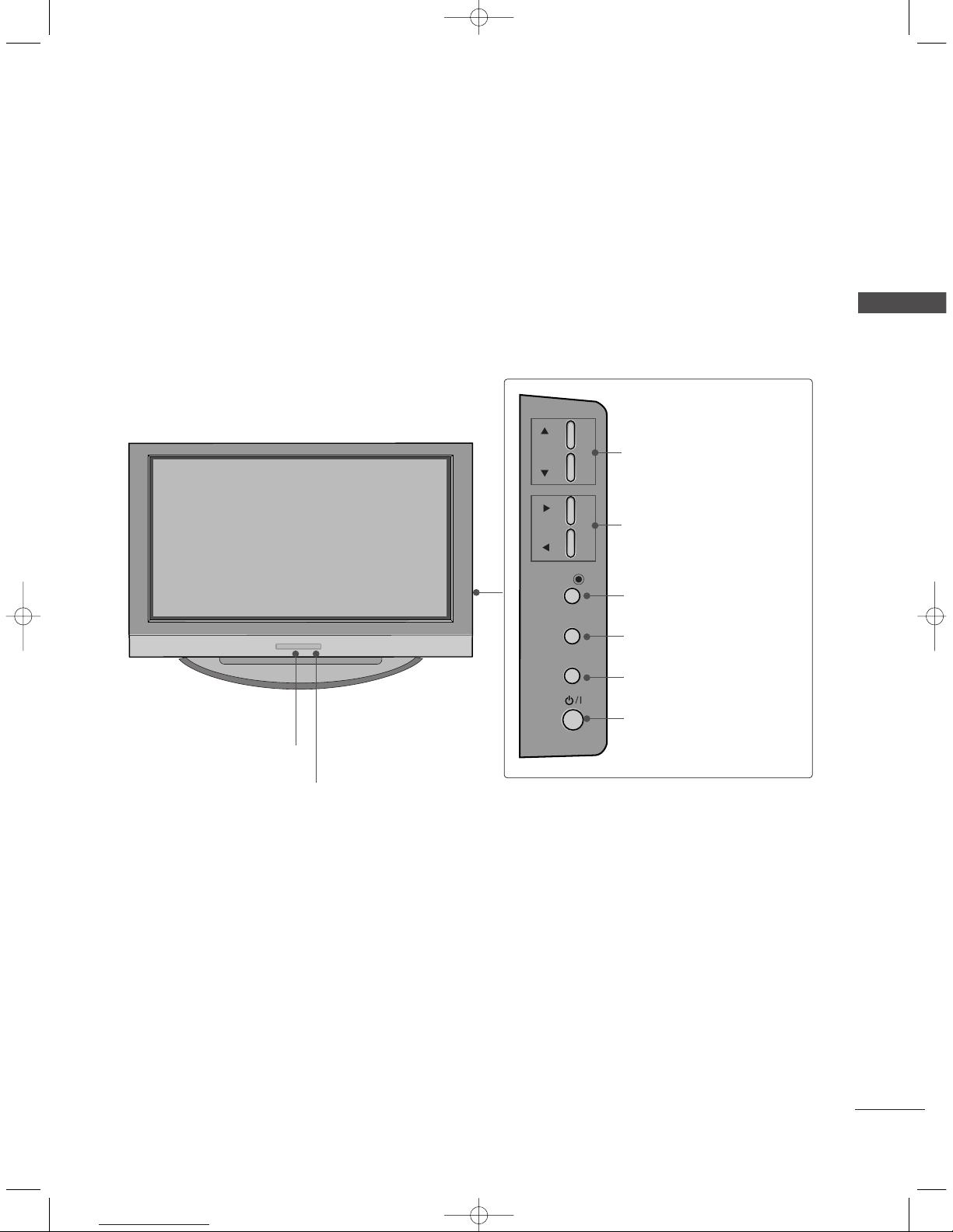
This is the front panel of models 42PC3RV*TVs.
■
This is a simplified representation of the front panel. Here shown may be somewhat different from your TV.
Front Panel Controls
PR
VOL
OK
MENU
INPUT
Remote Control Sensor
Power/Standby Indicator
• illuminates red in standby mode.
• illuminates white when the set is switched on.
PROGRAMME Buttons
VOLUME Buttons
OK Button
MENU Button
INPUT Button
ON/OFF Button
0323G_1-en_rev04 6/5/06 3:34 PM Page 5
6
CONNECTION OPTION
INTRODUCTION
INTRODUCTION
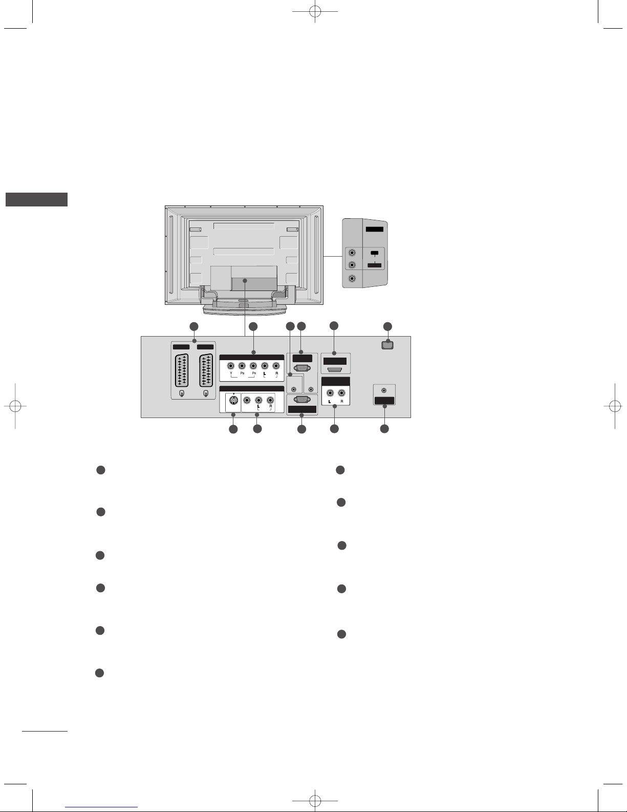
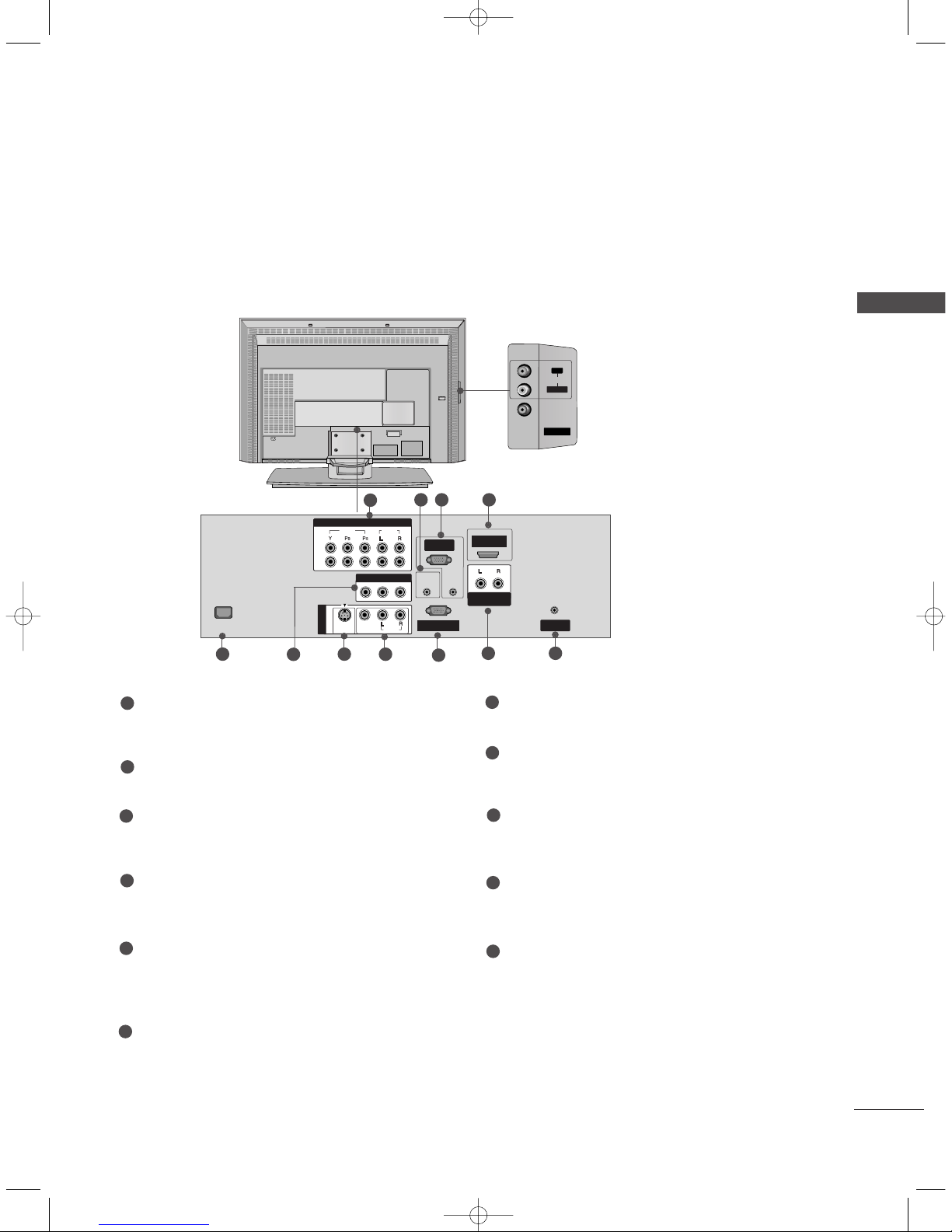
This is the back panel of models 42PC1RV*, 42PC3RV*, 42PC3RA*TVs. Here shown may be somewhat differ-
ent from your TV.
Back Connection Panel
42PC1RV*only
REMOTE
CONTROL IN
AUDIO IN
(RGB)
AC IN
AV 1 AV 2
MONO
( )
AUDIOUDIO
RGB IN
(PC/DTV)
RS-232C INRS-232C IN
(CONTROL & SERVICE)
HDMI IN
ANTENNA
IN
VIDEOVIDEO
S-VIDEOS-VIDEO
AV IN 3
AUDIO OUT
VARIABLE
VIDEOVIDEO
AUDIOUDIO
COMPONENT INCOMPONENT IN
AV IN 4
L/MONO
R
AUDIOAUDIO
VIDEOVIDEO
AUDIO Input
Connections are available for listening
stereo sound from an external device.
VIDEO Input
Connects the video signal from a video
device.
7
8
21
4
3
9
5
10 11
6
Euro Scart Socket (AV1/AV2)
Connect scart socket input or output from an
external device to these jacks.
Component Input
Connect a component video/audio device to
these jacks.
Remote Control Port
Connect your wired remote control here.
RGB/Audio Input
Connect the monitor output from a PC to the
appropriate input port.
HDMI Input
Connect a HDMI signal to HDMI port with HDMI
cable.
Power Cord Socket
This TV operates on an AC power. The voltage is
indicated on the Specifications page. Never
attempt to operate the TV on DC power.
S-Video Input
Connect S-Video out from an S-VIDEO device.
Audio/Video Input
Connect audio/video output from an external
device to these jacks.
RS-232C Input
(CONTROL&SERVICE) Port
Connect the serial port of the control devices to
the RS-232C jack.
Variable Audio Output
Connect an external amplifier or add a subwoofer
to your surround sound system.
Antenna Input
Connect over-the-air signals to this jack.
1
2
3
4
5
6
7
8
9
10
11
0323A_en_1_rev08 10/26/06 10:49 AM Page 6

7
INTRODUCTION
This is the front panel of models 26LC2R*, 32LC2R*TVs.
■
This is a simplified representation of the front panel. Here shown may be somewhat different from your TV.
Front Panel Controls
PR
VOL
OK
MENU
INPUT
R
/I
Remote Control Sensor
Power/Standby Indicator
• illuminates red in standby mode.
• illuminates white when the set is switched on.
PROGRAMME Buttons
VOLUME Buttons
OK Button
MENU Button
INPUT Button
ON/OFF Button
Stand
• This feature is not available for all models.
0323G_1-en_rev04 6/5/06 3:34 PM Page 7
8
CONTROLS
INTRODUCTION
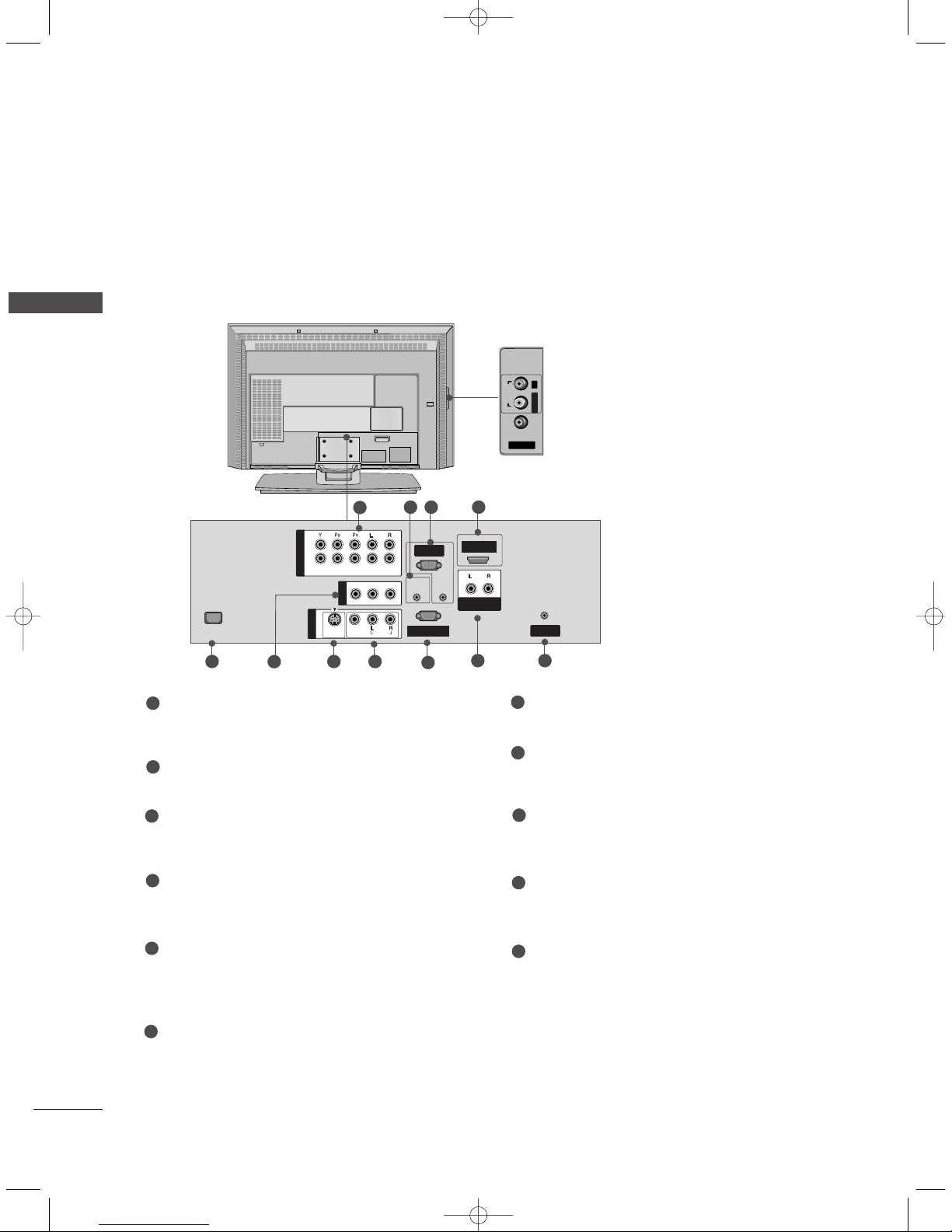
This is the back panel of models 26LC2R*TVs.
AV IN 2
AUDIOAUDIOVIDEOVIDEO
L/MONO
R
AC IN
RGB IN
(PC/DTV)
RS-232C INRS-232C IN
(CONTROL & SERVICE)
REMOTE
CONTROL IN
AUDIO IN
(RGB)
ANTENNA
IN
1
2
VIDEOVIDEO
AUDIOUDIO
AC IN
MONO
( )
AUDIOUDIO
VIDEOVIDEO
S-VIDEOS-VIDEO
AV IN 1
AV OUT
HDMI IN
COMPONENT IN
AUDIO OUT
VARIABLE
Back Connection Panel
AUDIO Input
Connections are available for listening
stereo sound from an external device.
VIDEO Input
Connects the video signal from a video
device.
1
9
8
2 43
75
6
1110
Component1/2 Input
Connect a component video/audio device to
these jacks.
Remote Control Port
Connect your wired remote control here.
RGB/Audio Input
Connect the monitor output from a PC/DTV to
the appropriate input port.
HDMI Input
Connect a HDMI signal to HDMI port with HDMI
cable.
Power Cord Socket
This TV operates on an AC power. The voltage is
indicated on the Product Specifications page.
Never attempt to operate the TV on DC power.
AV Output
Connect second TV or monitor to the AV OUT
socket on the set.
S-Video Input
Connect S-Video out from an S-VIDEO device.
Audio/Video Input
Connect audio/video output from an external
device to these jacks.
RS-232C Input
(CONTROL&SERVICE) Port
Connect the serial port of the control devices to
the RS-232C jack.
Variable Audio Output
Connect an external amplifier or add a subwoofer
to your surround sound system.
Antenna Input
Connect over-the-air signals to this jack.
1
2
3
4
7
5
6
8
9
10
11
0323G_1-en_rev04 6/5/06 3:34 PM Page 8
9
INTRODUCTION
AC IN
AV IN 2
L/MONO
R
AUDIOAUDIO
VIDEOVIDEO
COMPONENT INCOMPONENT IN
RGB IN
(PC/DTV)
RS-232C INRS-232C IN
(CONTROL & SERVICE)
REMOTE
CONTROL IN
AUDIO IN
(RGB)
ANTENNA
IN
1
2
VIDEOVIDEO
AUDIOUDIO
AC IN
MONO
( )
AUDIOUDIO
VIDEOVIDEO
S-VIDEOS-VIDEO
AV IN 1V IN 1
HDMI IN
AV OUTV OUT
AUDIO OUT
VARIABLE
This is the back panel of models 32LC2R*TVs.
Back Connection Panel
AUDIO Input
Connections are available for listening
stereo sound from an external device.
VIDEO Input
Connects the video signal from a video
device.
Component1/2 Input
Connect a component video/audio device to
these jacks.
Remote Control Port
Connect your wired remote control here.
RGB/Audio Input
Connect the monitor output from a PC/DTV to
the appropriate input port.
HDMI Input
Connect a HDMI signal to HDMI port with HDMI
cable.
Power Cord Socket
This TV operates on an AC power. The voltage is
indicated on the Product Specifications page.
Never attempt to operate the TV on DC power.
AV Output
Connect second TV or monitor to the AV OUT
socket on the set.
S-Video Input
Connect S-Video out from an S-VIDEO device.
Audio/Video Input
Connect audio/video output from an external
device to these jacks.
RS-232C Input
(CONTROL&SERVICE) Port
Connect the serial port of the control devices to
the RS-232C jack.
Variable Audio Output
Connect an external amplifier or add a subwoofer
to your surround sound system.
Antenna Input
Connect over-the-air signals to this jack.
1
2
3
4
7
5
6
8
9
10
11
1
9
8
2 43
75
6
1110
0323G_1-en_rev04 6/5/06 3:34 PM Page 9
10
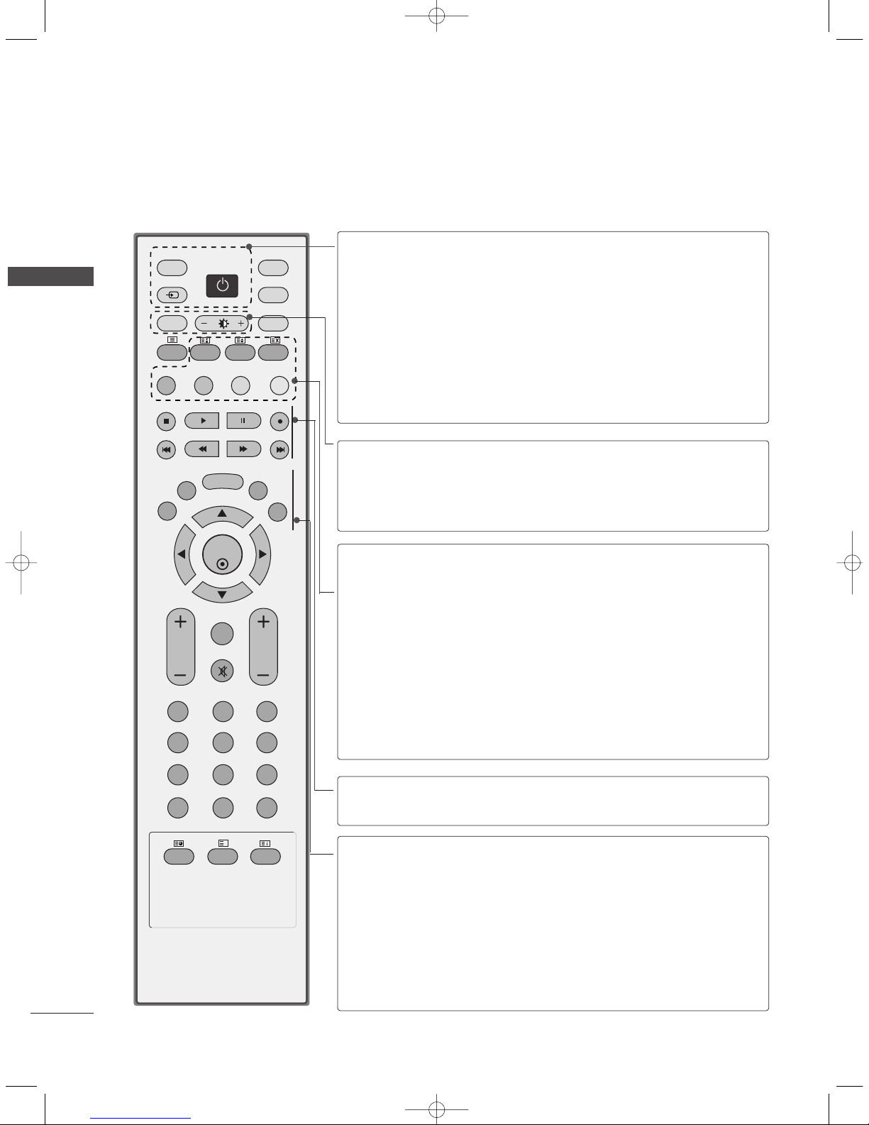
REMOTE CONTROL KEY FUNCTIONS
When using the remote control, aim it at the remote control sensor on the TV.
INTRODUCTION
INTRODUCTION
OK
INPUT
TVTV
PIP PR- PIP PR+
PIP INPUT
DVD
ARC
EXIT
VOL
TIME
REVEAL
INDEX
Q.VIEW
PR
SLEEP
LIST
I/II
MENU
PIP SIZE
POSTION
VCR
POWER
123
456
789
*
0
FAV
?
TEXT
INPUT
MUTE
POWER
TV INPUT
INPUT
Switches the set on from standby or off to standby.
Returns to the TV viewing from any mode.
Switches the set on from standby.
If you press the button once, the input source OSD
will appear on screen. Press the
DD/ EE
button and then
OK button to select the desired input source (TV, AV
(42PC3RV*)or AV1, AV2 (except 42PC3RV*),
Component1, Component2, RGB, HDMI).
Switches the set on from standby.
ARC
Brightness
adjustment
Selects your desired picture format.
Adjusts screen brightness.
It returns to the default settings brightness by changing
mode source.
PIP
SIZE
POSITION
PIP PR - /+
PIP INPUT
Coloured
buttons
Switches the sub picture PIP, DW mode.
Adjusts the sub picture size.
Moves the sub picture.
Selects a programme for the sub picture.
Selects the input source for the sub picture in PIP/Twin
picture mode.
These buttons are used for teletext (only
TTEELLEETTEEXXTT
models) or
PPrrooggrraa mmmmee eeddiitt
.
VCR/DVD
control buttons
Controls some video cassette recorders or DVD players
when you have already selected DVD or VCR mode button.
EXIT
LIST
MENU
I/II
SLEEP
Clears all on-screen displays and returns to TV viewing
from any menu.
Displays the programme table.
Selects a menu.
Selects the sound output.
Sets the sleep timer.
0323G_1-en_rev04 6/5/06 3:34 PM Page 10

11
INTRODUCTION
OK
INPUT
TVTV
PIP PR- PIP PR+
PIP INPUT
DVD
ARC
EXIT
VOL
TIME
REVEAL
INDEX
Q.VIEW
PR
SLEEP
LIST
I/II
MENU
TEXT PIP SIZE
POSTION
VCR
POWER
123
456
789
*
FAV
?
0
INPUT
MUTE
1
1
1
■
Open the battery compartment cover on the back side and install
the batteries matching correct polarity (+ with +, - with -).
■
Install two 1.5V AA batteries. Don’t mix old or used batteries with
new ones.
■
Close cover.
INSTALLING BATTERIES
MODE
Selects the remote operating modes.
TELETEXT
BUTTONS
These buttons are used for teletext.
For further details, see the ‘Teletext’ section.
THUMBSTICK
(Up/Down/Left
Right)
OK
Allows you to navigate the on-screen menus and adjust
the system settings to your preference.
Accepts your selection or displays the current mode.
VOLUME UP
/DOWN
Q.VIEW
MUTE
Programme
UP/DOWN
0~9 number
button
FAV
*
Adjusts the volume.
Returns to the previously viewed programme.
Switches the sound on or off.
Selects a programme.
Switches the set on from standby.
Selects a programme.
Selects numbered items in a menu.
Switches the set on from standby.
Displays the selected favourite programme.
No function
0323G_1-en_rev04 6/5/06 3:34 PM Page 11
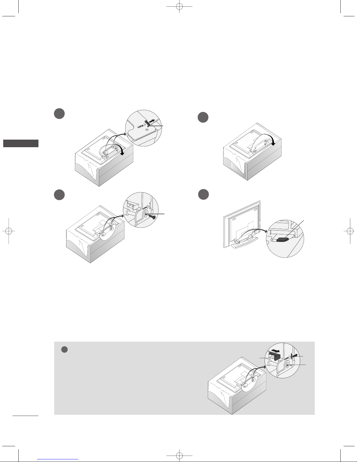
12
STAND INSTALLATION
INSTALLATION
INSTALLATION
Figures shown here may be slightly different from your set.
WWhheenn ccllooss ii nngg tthhee ssttaanndd ffoorr ssttoorraaggee
First remove the screws in the holes (B)on the bottom of the
stand.And then pull two Hooks (D)of the stand bottom and
fold the stand into the back of the set.
After folding,push two Locks (A)of the stand bottom outward.
NOTE
!
■
Place the set with the screen facing down on a cushion or soft cloth as shown in Figures 1.
Before unfolding the stand,please make sure two locks (A)on the bottom of the stand push outward.
■
Pull the stand out as shown above in Figures 2 ~ 3.
After unfolding the stand,please insert and tighten the screws in the holes (B)on the bottom of the stand.
■
When connecting cables to the set,Do not disengage the lock (C).
This may cause the set to fall,causing serious bodily injury and serious damage to the set.
A
C
B
1
2
3
4
■
This feature is not available for all models.
A
D
B
0323G_1-en_rev04 6/5/06 3:34 PM Page 12

INSTALLATION
13
STAND INSTALLATION (Only 32LC2R
*
)
1
2
3
Carefully place the set screen side down on a
cushioned surface that will protect set and
screen from damage.
Place the hook of the stand in the back of the set
as shown.
Install the 4 bolts provided securely, in the back
of the set.
■
This feature is not available for all models.
0323G_1-en_rev04 6/5/06 3:34 PM Page 13
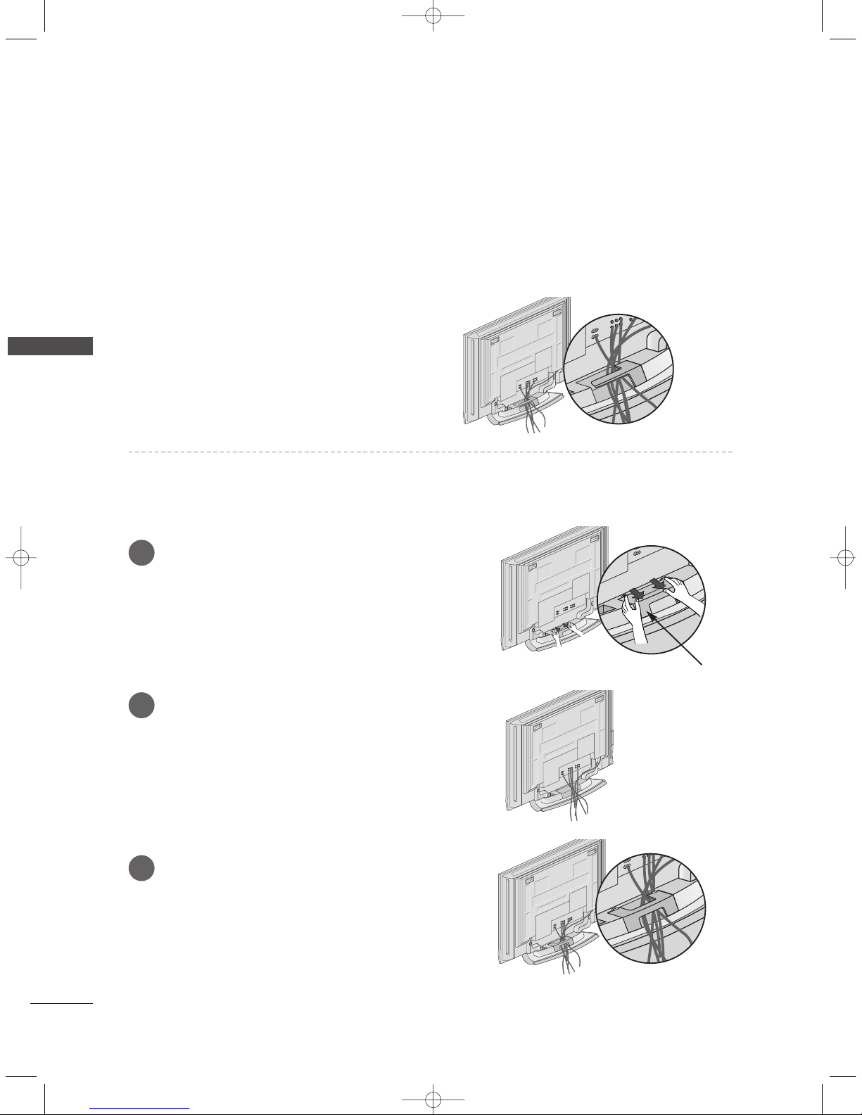
14
BASIC CONNECTION (42PC1RV
*
, 42PC3RV*)
INSTALLATION
INSTALLATION
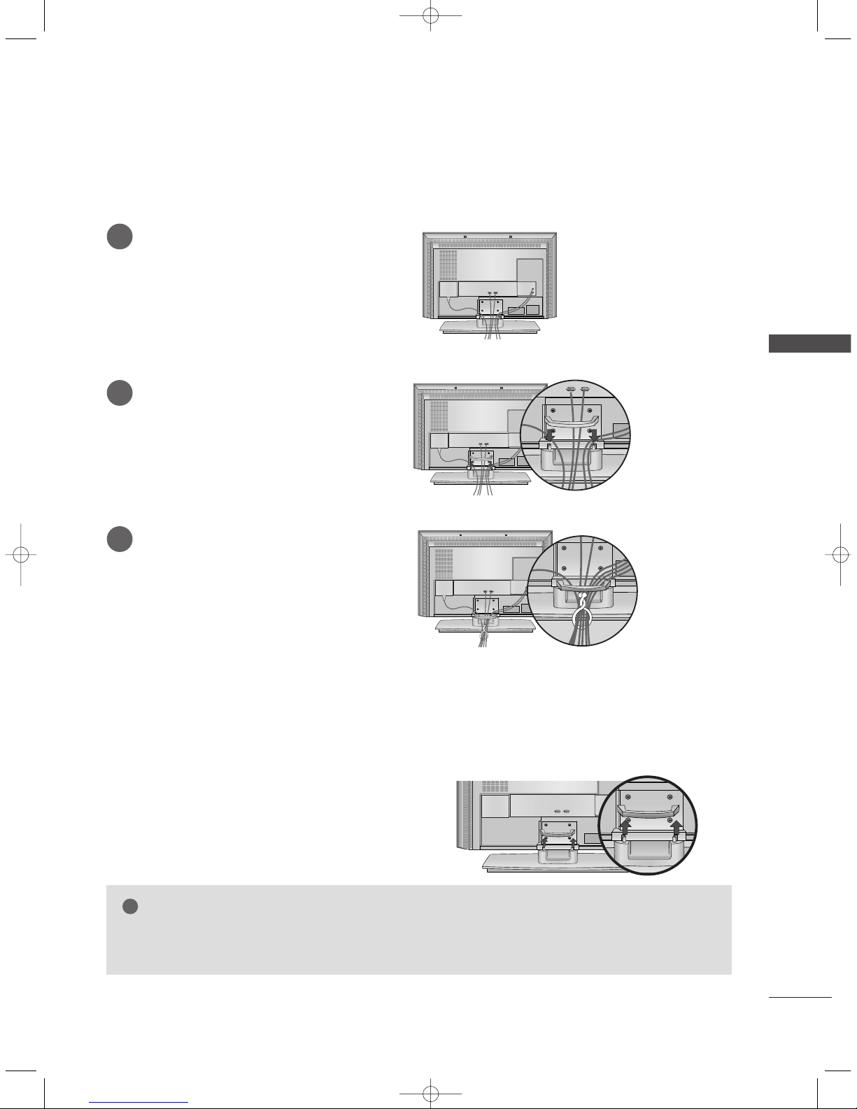
Arrange the cables as shown picture.
Hold the
CCAA BB LLEE MMAA NNAA GG EEMMEE NNTT
with both
hands and push it as shown.
Connect the cables as necessary.
To connect an additional equipment, see the
EExxttee rr nn aa ll eeqquuii ppmmeenntt CCoo nnnnee cctt ii oonnss
section.
Reinstall the
CCAA BB LLEE MMAA NNAA GG EEMMEE NNTT
as shown.
1
2
3
CABLE MANAGEMENT
■
These models have two cable arrangement methods according to the stand type.
Stand type 1
Stand type 2
0323G_1-en_rev04 6/5/06 3:34 PM Page 14
INSTALLATION
15
BASIC CONNECTION (Only 26LC2R
*
, 32LC2R*)
Connect the cables as necessary.
After connecting the cables neatly, arrange
the cables to the Cable Holder.
To connect an additional equipment, see
the
EExxtteerrnnaall eeqquuiippmmeenntt CCoonnnneeccttiioonnss
section.
1
Install the
CCAABB LLEE MMAA NNAAGGEEMMEENNTT
as shown.
2
Bundle the cables using the supplied
twister holder.
3
Hold the
CCAA BBLLEE MMAANN AA GG EE MMEE NN TT
with both
hands and pull it upward.
NOTE
!
GG
Do not hold the CABLE MANAGEMENT when moving the product.
- If the product is dropped, you may be injured or the product may be broken.
HOW TO REMOVE THE CABLE MANAGEMENT
0323G_1-en_rev04 6/5/06 3:34 PM Page 15

16
INSTALLATION
INSTALLATION
INSTALLATION
Desktop Pedestal Installation
4 inches
4 inches4 inches
4 inches
For proper ventilation, allow a clearance of 4" on each side and from the wall.
Wall Mount: Horizontal installation
4 inches
4 inches
4 inches
4 inches
4 inches
For proper ventilation, allow a clearance of 4" on each side and from the wall. Detailed installation instructions are available from your dealer, see the optional Tilt Wall Mounting Bracket Installation and Setup Guide.
GROUNDING
Ensure that you connect the earth ground wire to prevent
possible electric shock. If grounding methods are not possible, have a qualified electrician install a separate circuit
breaker. Do not try to ground the unit by connecting it to
telephone wires, lightening rods, or gas pipes.
Power
Supply
Short-circuit
Breaker
■
The TV can be installed in various ways such as on a wall, or on a desktop etc.
■
The TV is designed to be mounted horizontally.
<< OOnn ll yy 44 22PPCC11RRVV*,, 4422PP CC33 RR VV*sseerriieess>>
Remove two screws of the backside of the set before
installing the wall mounting bracket.
0323G_1-en_rev04 6/5/06 3:34 PM Page 16
INSTALLATION
17
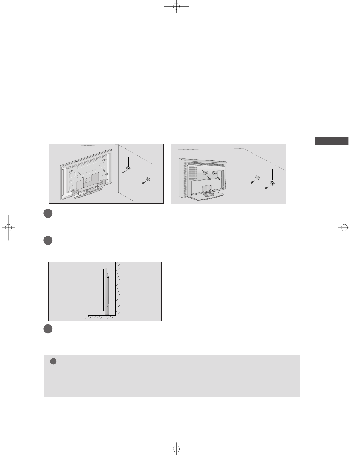
HOW TO JOIN THE PRODUCT ASSEMBLY TO THE WALL TO
PROTECT THE SET TUMBLING
42PC1RV*, 42PC3RV
*
26LC2R*, 32LC2R
*
2
1
■
Set it up close to the wall so the product doesn’t fall over when it is pushed backwards.
■
The instructions shown below is a safer way to set up the product, which is to fix it on the wall so the
product doesn’t fall over when it is pulled in the forward direction. It will prevent the product from
falling for-ward and hurting people. It will also prevent the product from damage caused by fall. Please
make sure that children don’t climb on or hang from the product.
NOTE
!
GG
When moving the product to another place undo the ropes first.
GG
Use a product holder or a cabinet that is big and strong enough for the size and weight of the product.
GG
To use the product safely make sure that the height of the bracket that is mounted on the wall is same
as that of the product.
2
3
1
1
2
Use the eye-bolts or TV brackets/bolts to fix the product to the wall as shown in the picture.
(If your product has the bolts in the eye-bolts position before inserting the eye-bolts, loosen the bolts.)
* Insert the eye-bolts or TV brackets/bolts and tighten them securely in the upper holes.
Secure the wall brackets with the bolts (not provided as parts of the product, must purchase separately) on the wall. Match the height of the bracket that is mounted on the wall.
3
Use a sturdy rope (not provided as parts of the product, must purchase separately) to tie the
product. It is safer to tie the rope so it becomes horizontal between the wall and the product.
0323G_1-en_rev04 6/5/06 3:34 PM Page 17
18
ANTENNA CONNECTION
CONNECTIONS & SETUP
CONNECTIONS & SETUP
■
To prevent the equipment damage, never plug in any power cords until you have finished connecting all equipment.
■
For optimum picture quality, adjust antenna direction.
■
An antenna cable and converter are not supplied.
■
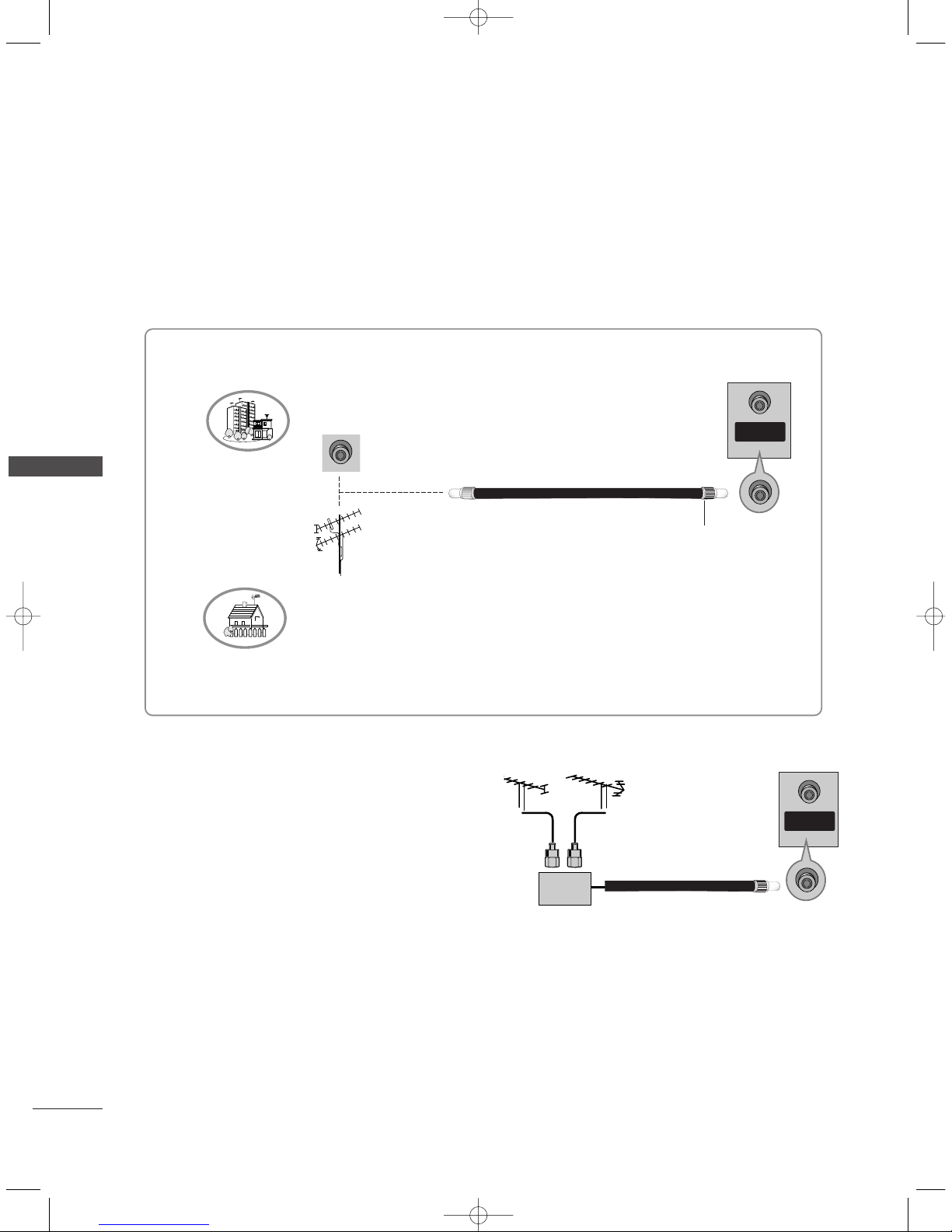
In poor signal areas, to get better picture quality,
install a signal amplifier to the antenna as shown
to the right.
■
If signal needs to be split for two TVs, use an
antenna signal splitter for connection.
SSiiggnnaall
AAmmpplliiffiieerr
UHF
VHF
Multi-family Dwellings/Apartments
(Connect to wall antenna socket)
Single-family Dwellings /Houses
(Connect to wall jack for outdoor antenna)
Outdoor Antenna
Wall Antenna Socket
VHF Antenna
UHF Antenna
RF Coaxial Wire (75 ohm)
Turn clockwise to tighten.
ANTENNA
IN
ANTENNA
IN
0323G_1-en_rev04 6/5/06 3:34 PM Page 18
CONNECTIONS & SETUP
19
VCR SETUP
■
To avoid picture noise (interference), leave an adequate distance between the VCR and TV.
■
Typically a frozen still picture from a VCR. If the 4:3 picture format is used; the fixed images on the sides
of the screen may remain visible on the screen.
■
This part of CONNECTIONS & SETUP mainly use pictures for the 42PC1RV*, 42PC3RV*models.
S-VIDEO
OUT
IN
(R) AUDIO (L) VIDEO
34
OUTPUT
SWITCH
ANT OUT
ANT IN
HDMI IN
AUDIO OUT
VARIABLE
ANTENNA
IN
VV CCRR
1
2
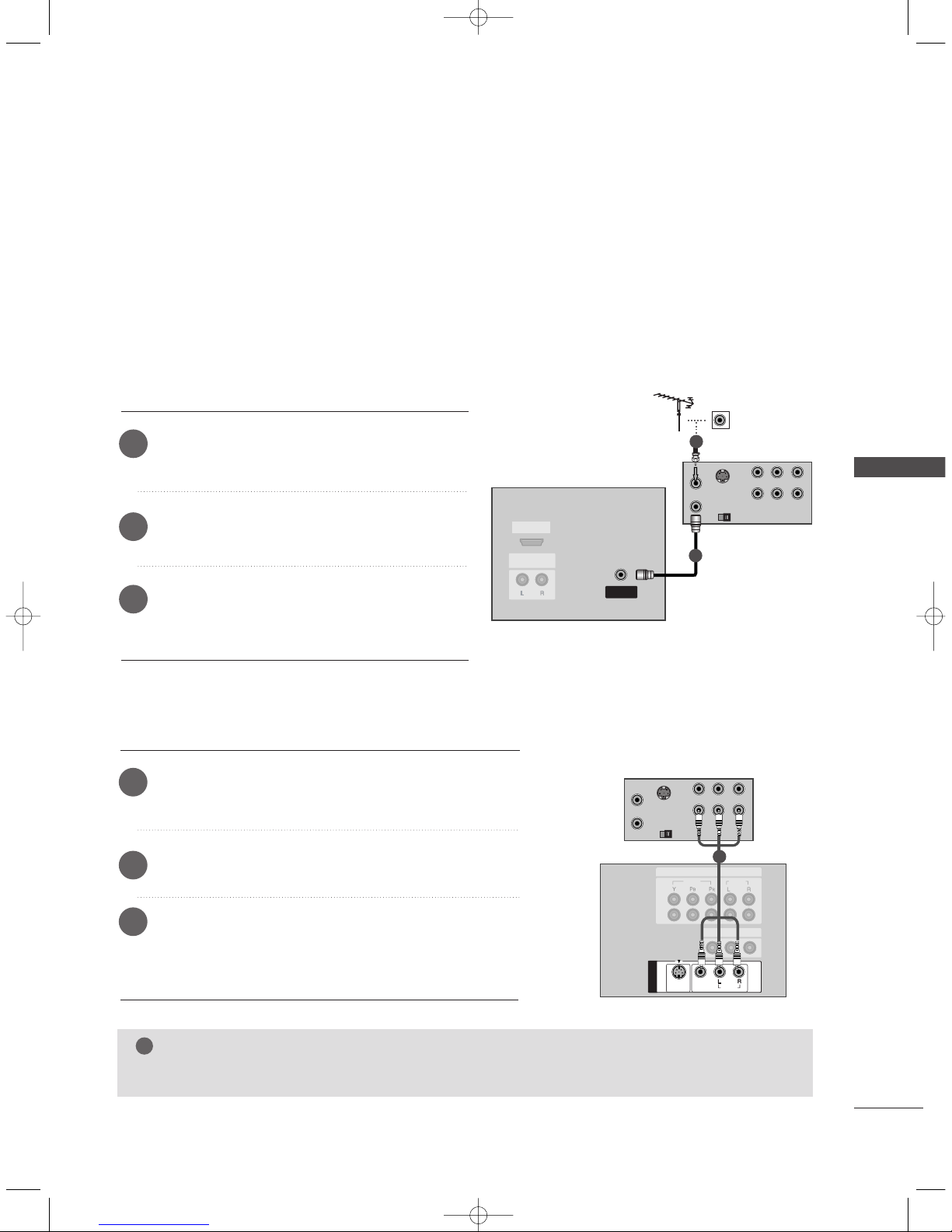
When connecting with an antenna
Connect the
AANNTT OOUUTT
socket of the VCR to the
AANNTTEENNNNAA II NN
socket on the set.
Connect the antenna cable to the
AANNTT II NN
socket of the VCR.
Press the
PPLLAAYY
button on the VCR and match the
appropriate programme between the TV and VCR
for viewing.
1
2
3
S-VIDEO
OUT
IN
(R) AUDIO (L) VIDEO
34
OUTPUT
SWITCH
ANT OUT
ANT IN
MONO
( )
AUDIO
VIDEO
S-VIDEO
AV IN 1
AV OUT
VIDEO
AUDIO
2
1
COMPONENT IN
AUDIO OUT
VARIABLE
ANTENNA
IN
VV CCRR
1
When connecting with a RCA cable
Connect the
AA UUDDIIOO/VV IIDDEE OO
jacks between TV and VCR.
Match the jack colors (Video = yellow, Audio Left = white,
and Audio Right = red).
Insert a video tape into the VCR and press PLAY on the
VCR. (Refer to the VCR owner’s manual.)
Select AV or AV 1 input source using the
IINNPPUUTT
button
on the remote control.
- If connected to
AA VVII NN 22
, select AV 2 input source.
(except 42PC3RV*)
1
2
3
NOTE
!
GG
If you have a mono VCR, connect the audio cable from the VCR to the
AAUUDDIIOO LL//MMOO NNOO
jack of the set.
0323G_1-en_rev04 6/23/06 11:49 AM Page 19

20
VCR SETUP
CONNECTIONS & SETUP
CONNECTIONS & SETUP
S-VIDEO
OUT
IN
(R) AUDIO (L) VIDEO
34
OUTPUT
SWITCH
ANT OUT
ANT IN
( )
AUDIO
VIDEO
S-VIDEO
AV IN 1
2
1
MONO
( )
AUDIO
VIDEO
S-VIDEO
AV IN 1
AV OUT
VIDEO
AUDIO
2
1
COMPONENT IN
AUDIO OUT
VARIABLE
ANTENNA
IN
VV CCRR
1
2
When connecting with an S-Video cable
Connect the S-VIDEO output of the VCR to the
SS--VVIIDDEEOO
input on the set. The picture quality is improved; compared to normal composite (RCA cable) input.
Connect the audio outputs of the VCR to the
AA UUDDIIOO
input jacks on the set.
Insert a video tape into the VCR and press PLAY on the
VCR. (Refer to the VCR owner’s manual.)
1
2
3
Select AV or AV 1 input source with using the
IINNPPUUTT
button on the remote control.
4
NOTE
!
GG
If both S-VIDEO and VIDEO sockets have been conneced to the S-VHS VCR simultaneously, only the SVIDEO can be received.
0323G_1-en_rev04 6/5/06 3:34 PM Page 20

CONNECTIONS & SETUP
21
EXTERNAL EQUIPMENT CONNECTIONS
AV IN 2V IN 2
L/MONOMONO
R
AUDIOAUDIO
VIDEOVIDEO
RL
AUDIO VIDEO
Camcorder
Video Game Set
1
Connect the
AA UUDDIIOO/VV IIDDEE OO
jacks between TV
and external equipment. Match the jack colors
(Video = yellow, Audio Left = white, and Audio Right
= red)
Select AV2 input source with using the
IINNPPUUTT
button on the remote control. (except 42PC3RV*)
- If connected to
AAVV IINN11
input, select AV1 input
source.
- If connected to
AA VV IINN
input, select AV input
source. (42PC3RV*)
Operate the corresponding external equipment.
Refer to external equipment operating guide.
1
2
3
0323G_1-en_rev04 6/5/06 3:34 PM Page 21
22
DVD SETUP
CONNECTIONS & SETUP
CONNECTIONS & SETUP
MONO
( )
AUDIOUDIO
VIDEOVIDEO
S-VIDEOS-VIDEO
AV IN 1
AV OU T
VIDEO
AUDIO
2
1
COMPONENT IN
COMPONENT IN
2
1
VIDEO
AUDIO
S-VIDEO
(R) AUDIO (L)
DDVV DD
1
2
AV IN 1
AV OUT
COMPONENT INCOMPONENT IN
2
1
VIDEOVIDEO
AUDIOUDIO
MONO
( )
AUDIO
VIDEO
S-VIDEO
B
R
(R) AUDIO (L)
DDVV DD
1
2
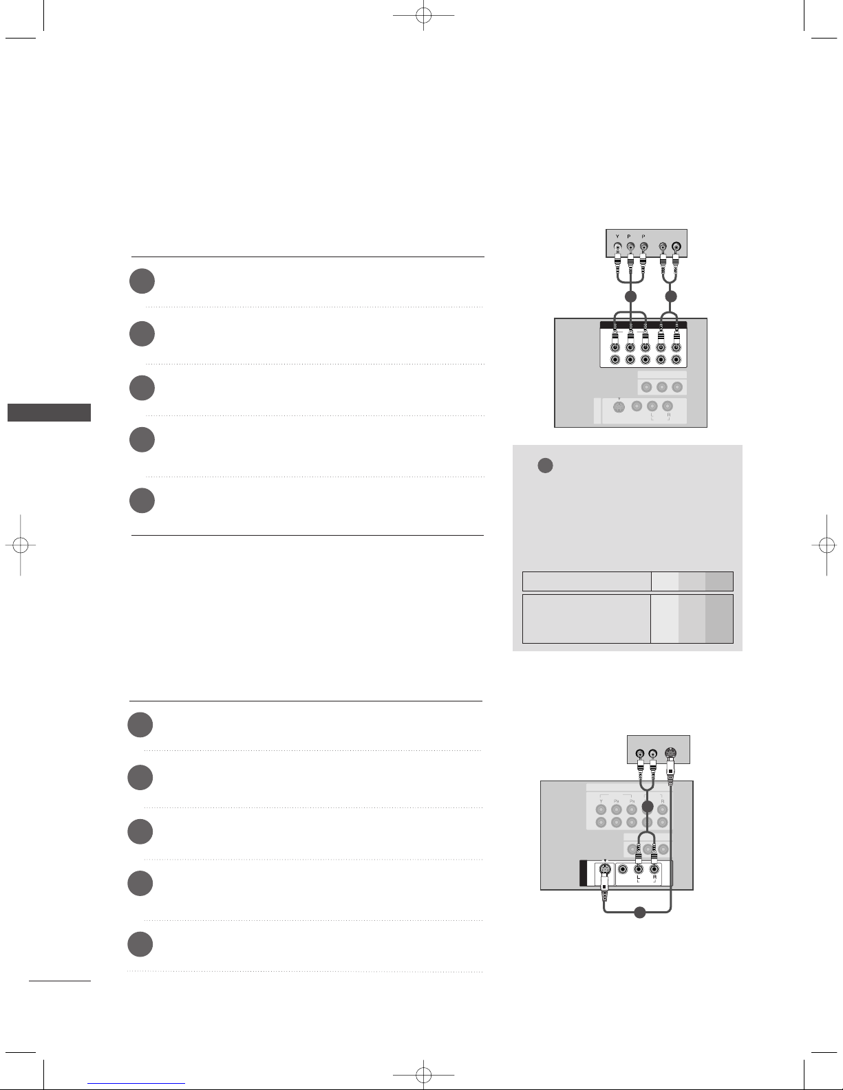
When connecting with a component cable
Connect the video outputs (Y, PB
, PR) of the DVD to the
CCOO MMPPOONNEENN TT VVII DDEE OO
jacks on the set.
Connect the audio outputs of the DVD to the
CCOOMMPP OO--
NN EENN TT AAUUDDIIOO
jacks on the set.
Turn on the DVD player, insert a DVD.
1
2
3
Select Component1 or Component2 input source
with using the
IINNPPUUTT
button on the remote control.
4
Refer to the DVD player's manual for operating instructions.
5
When connecting with a S-Video cable
Connect the S-VIDEO output of the DVD to the
SS--VVIIDDEEOO
input on the set.
Connect the audio outputs of the DVD to the
AA UUDDIIOO
input jacks on the set.
Turn on the DVD player, insert a DVD.
1
2
3
Select AV 1 input source with using the
IINNPPUUTT
button on
the remote control.
4
Refer to the DVD player's manual for operating instructions.
5
NOTE
!
GG
CCoommppoonneenntt IInn pp uutt ppoorr ttss
To get better picture quality,
connect a DVD player to the
component input ports as shown
below.
Y PB
P
R
Component ports on the TV
Y
Y
Y
Y
Pb
B-Y
Cb
PB
Pr
R-Y
Cr
PR
Video output ports
on DVD player
0323G_1-en_rev04 6/5/06 3:34 PM Page 22
CONNECTIONS & SETUP
23
REMOTE
CONTROL IN
AUDIO IN
(RGB)
RGB INRGB IN
(PC/DTV)
RS-232C INRS-232C IN
(CONTROL & SERSERVICE)VICE)
AUDIO OUTUDIO OUT
VARIABLE
HDMI IN
HDMI-DVD OUTPUT
DDVV DD
11
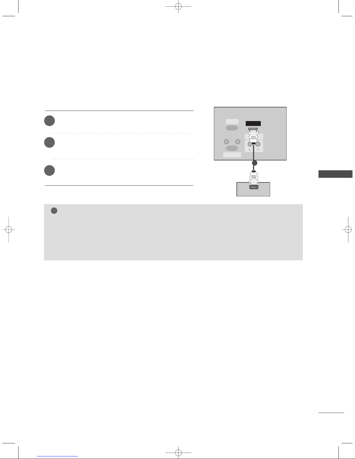
When connecting with a HDMI cable
Connect the HDMI output of the DVD to the
HH DDMMII IINN
jack on the set.
Select HDMI input source with using the
IINNPPUUTT
button
on the remote control.
Refer to the DVD player's manual for operating instructions.
1
2
3
NOTE
!
GG
TV can receive the video and audio signal simultaneously with using a HDMI cable.
GG
If the DVD supports Auto HDMI function, the DVD output resolution will be automatically set to
1280x720p.
GG
If the DVD does not support Auto HDMI, you need to set the output resolution appropriately. To get the
best picture quality, adjust the output resolution of the DVD to 1280x720p.
0323G_1-en_rev04 6/5/06 3:34 PM Page 23
24
STB (SET-TOP BOX) SETUP
CONNECTIONS & SETUP
CONNECTIONS & SETUP
RGB IN
(PC/DTV)(PC/DTV)
RS-232C IN
(CONTROL & SERVICE)
AUDIO OUTUDIO OUT
VARIABLE
HDMI INHDMI IN
REMOTE
CONTROL IN
AUDIO IN
(RGB)
(R) AUDIO (L)
DVI-DTV OUTPUT
DD iiggiitt aall SSee tt--tt oopp
BB ooxx
1
2
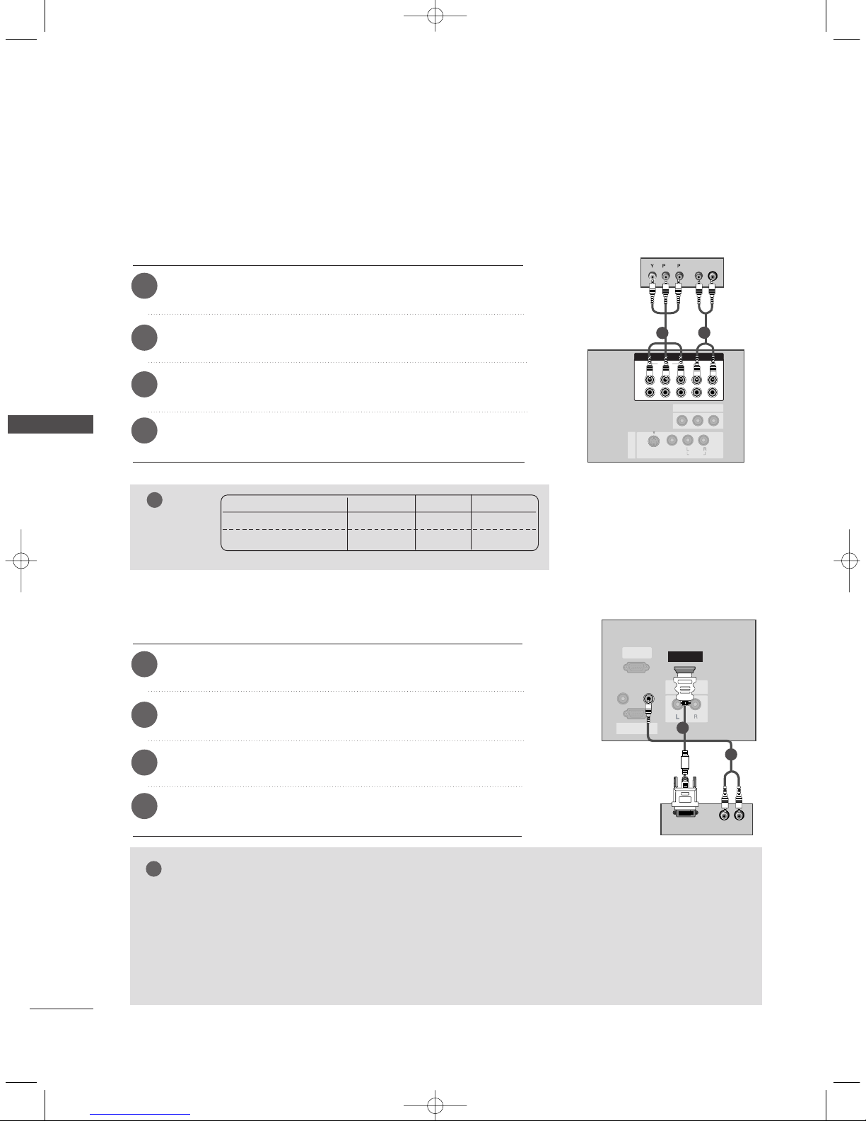
When connecting with a component cable
Connect the video outputs (Y, P
B, PR) of the digital set-top box
to the
CCOO MMPPOONNEENN TT VVII DDEE OO
jacks on the set.
Connect the audio output of the digital set-top box to the
CCOO MMPPOONNEENN TT AA UUDDIIOO
jacks on the set.
Turn on the digital set-top box. (Refer to the owner’s manual for
the digital set-top box.)
1
2
3
Select Component1 or Component2 input source with
using the
IINNPPUUTT
button on the remote control.
4
NOTE
!
Signal
480i/576i
480p/576p/720p/1080i
Component
Yes
Yes
RGB-DTV
No
Yes
HDMI
No
Yes
When connecting with a HDMI to DVI cable
Connect the DVI output of the digital set-top box to the
HH DDMM II
II NN
jack on the set.
Connect the audio outputs of the set-top box to the
AA UUDDIIOO
IINN ((RR GG BB))
jack on the set.
Turn on the digital set-top box. (Refer to the owner’s manual for
the digital set-top box.)
1
2
3
Select HDMI input source with using the
IINNPPUUTT
button on the
remote control.
4
GG
If the digital set-top box has a DVI output and no HDMI output, a separated audio connection is necessary.
GG
If the digital set-top box supports Auto DVI function, the output resolution of the digital set-top box will
be automatically set to 1280x720p.
GG
If the digital set-top box does not support Auto DVI, you need to set the output resolution appropriately.
To get the best picture quality, adjust the output resolution of the digital set-top box to 1280x720p.
NOTE
!
AV IN 1
AV OU T
COMPONENT INCOMPONENT IN
2
1
VIDEOVIDEO
AUDIOUDIO
MONO
( )
AUDIO
VIDEO
S-VIDEO
B
R
(R) AUDIO (L)
DD iiggiitt aall SSee tt--tt oopp BBooxx
1
2
0323G_1-en_rev04 6/5/06 3:34 PM Page 24

CONNECTIONS & SETUP
25
(R) AUDIO (L)
RGB-DTV OUTPUT
REMOTE
CONTROL IN
RS-232C INRS-232C IN
(CONTR(CONTROL & SERSERVICE)VICE)
HDMI IN
AUDIO OUTUDIO OUT
VARIABLE
RGB INRGB IN
(PC/DTV)
AUDIO IN
(RGB)
RGB IN
(PC/DTV)
RS-232C IN
(CONTROL & SERVICE)
AUDIO OUT
VARIABLE
HDMI IN
DD iiggiitt aall
SSee tt --ttoo pp BB oo xx
1
2
When connecting with a D-sub 15 pin cable
Connect the RGB output of the digital set-top box to the
RR GG BB II NN ((PPCC//DDTTVV))
jack on the set.
Connect the audio outputs of the set-top box to the
AAUUDDIIOO IINN ((RRGGBB))
jack on the set.
Turn on the digital set-top box. (Refer to the owner’s
manual for the digital set-top box.)
1
2
3
Select RGB-DTV input source with using the
IINNPPUUTT
button on the remote control.
4
REMOTE
CONTROL IN
AUDIO IN
(RGB)
RGB INRGB IN
(PC/DTV)
RS-232C INRS-232C IN
(CONTR(CONTROL & SERSERVICE)VICE)
AUDIO OUTUDIO OUT
VARIABLE
HDMI IN
HDMI-DVD OUTPUT
11
When connecting with a HDMI cable
Connect the HDMI output of the digital set-top box to the
HH DDMMII II NN
jack on the set.
Select HDMI input source with using the
IINNPPUUTT
button
on the remote control.
Turn on the digital set-top box. (Refer to the owner’s manual for the digital set-top box.)
1
2
3
NOTE
!
GG
TV can receive the video and audio signal simultaneously with using a HDMI cable.
GG
If the digital set-top box supports Auto HDMI function, output resolution of the digital set-top box will be
automatically set to 1280x720p.
GG
If the digital set-top box does not support Auto HDMI, you need to set the output resolution appropriately. To get the best picture quality, adjust the output resolution of the digital set-top box to
1280x720p.
DD iiggiitt aall
SSee tt --ttoo pp BB oo xx
0323G_1-en_rev04 6/5/06 3:34 PM Page 25
 Loading...