

Page 1
Please read this manual carefully before operating
your set.
Retain it for future reference.
Record model number and serial number of the set.
See the label attached on the back cover and quote
this information to your dealer
when you require service.
LCD TV PLASMA TV
OWNER’S MANUAL
LCD TV MODEL
32LB9D
PLASMA TV MODELS
42PB4DA
50PB4DA
60PB4DA
P/NO : MFL34797022 (0708-REV01)
Printed in Korea
www.lgusa.com
As an ENERGY STAR
Partner LGE U. S. A.,Inc.
has determined that this
product meets the
ENERGY STAR guidelines
for energy efficiency.
ENERGY STAR is a set of power-saving
guidelines issued by the U.S.
Environmental Protection Agency(EPA).
An extended owner’s manual that contains information
on the advanced features of these LG TV sets is located
on the CD-ROM provided in an electronic version.
To read these files, you will need to use personal computer
(PC) equipped with a CD-ROM drive.
Page 2
2
WARNING / CAUTION
WARNING / CAUTION
To prevent fire or shock hazards, do not expose
this product to rain or moisture.
FCC NOTICE
Class B digital device
This equipment has been tested and found to comply with the limits for a Class B digital device, pursuant to Part 15 of the FCC Rules. These limits are
designed to provide reasonable protection against
harmful interference in a residential installation. This
equipment generates, uses and can radiate radio frequency energy and, if not installed and used in
accordance with the instructions, may cause harmful
interference to radio communications. However,
there is no guarantee that interference will not
occur in a particular installation. If this equipment
does cause harmful interference to radio or television reception, which can be determined by turning
the equipment off and on, the user is encouraged to
try to correct the interference by one or more of
the following measures:
- Reorient or relocate the receiving antenna.
- Increase the separation between the equipment
and receiver.
- Connect the equipment to an outlet on a circuit
different from that to which the receiver is connected.
- Consult the dealer or an experienced radio/TV
technician for help.
Any changes or modifications not expressly
approved by the party responsible for compliance
could void the user’s authority to operate the
equipment.
CAUTION
Do not attempt to modify this product in any way
without written authorization from LG Electronics.
Unauthorized modification could void the user’s
authority to operate this product
The lightning flash with arrowhead
symbol, within an equilateral triangle,
is intended to alert the user to the
presence of uninsulated “dangerous voltage”
within the product’s enclosure that may be of
sufficient magnitude to constitute a risk of electric
shock to persons.
The exclamation point within an equilateral
triangle is intended to alert the user to
the presence of important operating and maintenance (servicing) instructions in the literature
accompanying the appliance.
TO REDUCE THE RISK OF ELECTRIC SHOCK
DO NOT REMOVE COVER (OR BACK). NO
USER SERVICEABLE PARTS INSIDE. REFER TO
QUALIFIED SERVICE PERSONNEL.
WARNING/CAUTION
TO REDUCE THE RISK OF FIRE AND ELECTRIC
SHOCK, DO NOT EXPOSE THIS PRODUCT TO
RAIN OR MOISTURE.
NOTE TO CABLE/TV INSTALLER
This reminder is provided to call the CATV system
installer’s attention to Article 820-40 of the National
Electric Code (U.S.A.). The code provides guidelines for
proper grounding and, in particular, specifies that the
cable ground shall be connected to the grounding system of the building, as close to the point of the cable
entry as practical.
Page 3
3
IMPORTANT SAFETY INSTRUCTIONS
SAFETY INSTRUCTIONS
Important safety instructions shall be provided with each apparatus. This information shall be given in a separate
booklet or sheet, or be located before any operating instructions in an instruction for installation for use and
supplied with the apparatus.
This information shall be given in a language acceptable to the country where the apparatus is intended to be used.
The important safety instructions shall be entitled “Important Safety Instructions”. The following safety
instructions shall be included where applicable, and, when used, shall be verbatim as follows. Additional safety
information may be included by adding statements after the end of the following safety instruction list. At the
manufacturer’s option, a picture or drawing that illustrates the intent of a specific safety instruction may be
placed immediately adjacent to that safety instruction:
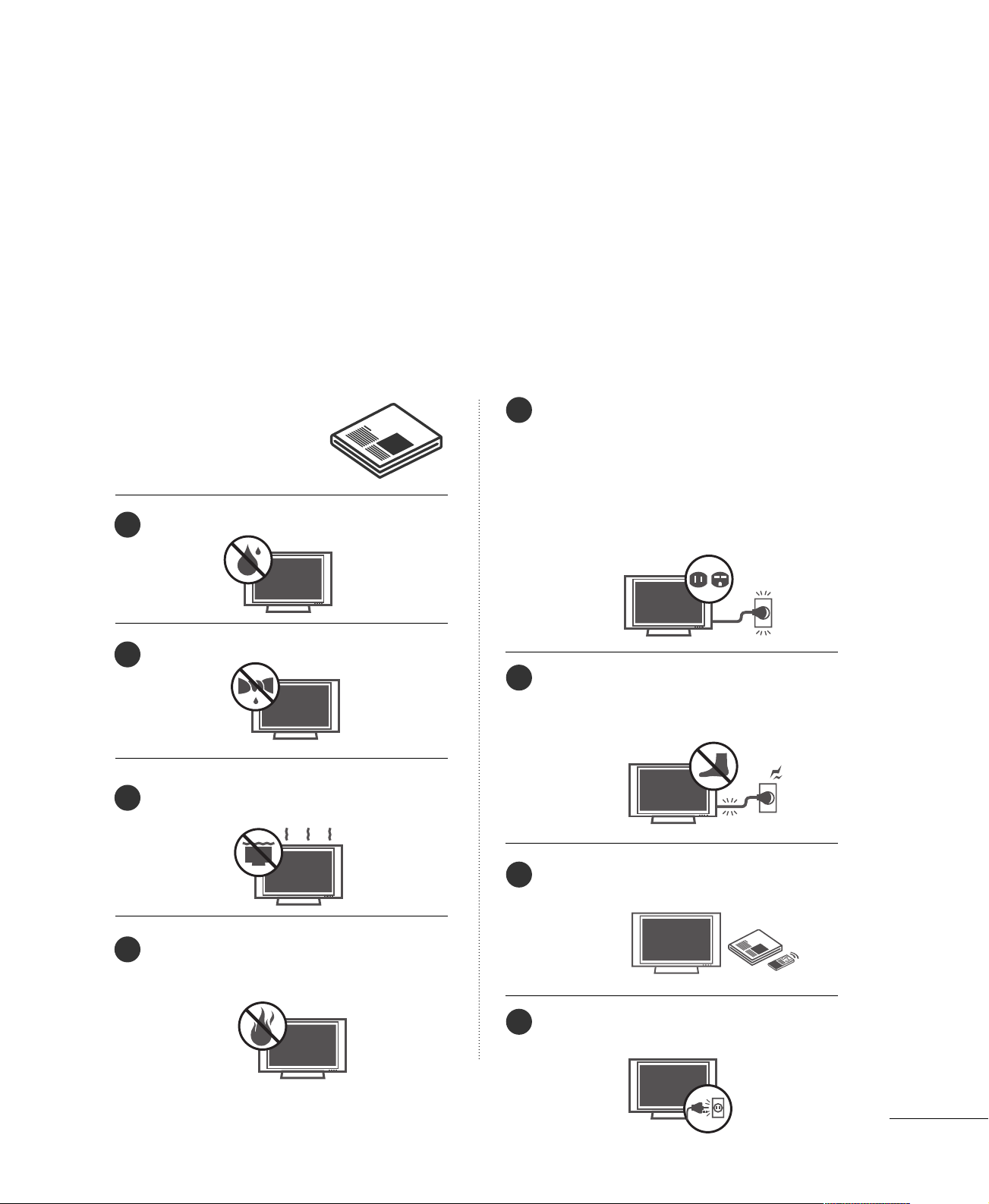
Read these instructions.
Keep these instructions.
Heed all warnings.
Follow all instructions.
Do not use this apparatus near water.
Clean only with dry cloth.
Do not block any ventilation openings. Install in
accordance with the manufacturer’s instructions.
Do not install near any heat sources such as
radiators, heat registers, stoves, or other apparatus
(including amplifiers)that produce heat.
Do not defeat the safety purpose of the polarized
or grounding-type plug. A polarized plug has
two blades with one wider than the other. A
grounding type plug has two blades and a third
grounding prong, The wide blade or the third
prong are provided for your safety. If the provided
plug does not fit into your outlet, consult an
electrician for replacement of the obsolete outlet.
Protect the power cord from being walked on
or pinched particularly at plugs, convenience
receptacles, and the point where they exit from
the apparatus.
Only use attachments/accessories specified by
the manufacturer.
Unplug this apparatus when unused for long
periods of time.
1
2
3
4
5
6
7
8
Page 4
4
SAFETY INSTRUCTIONS
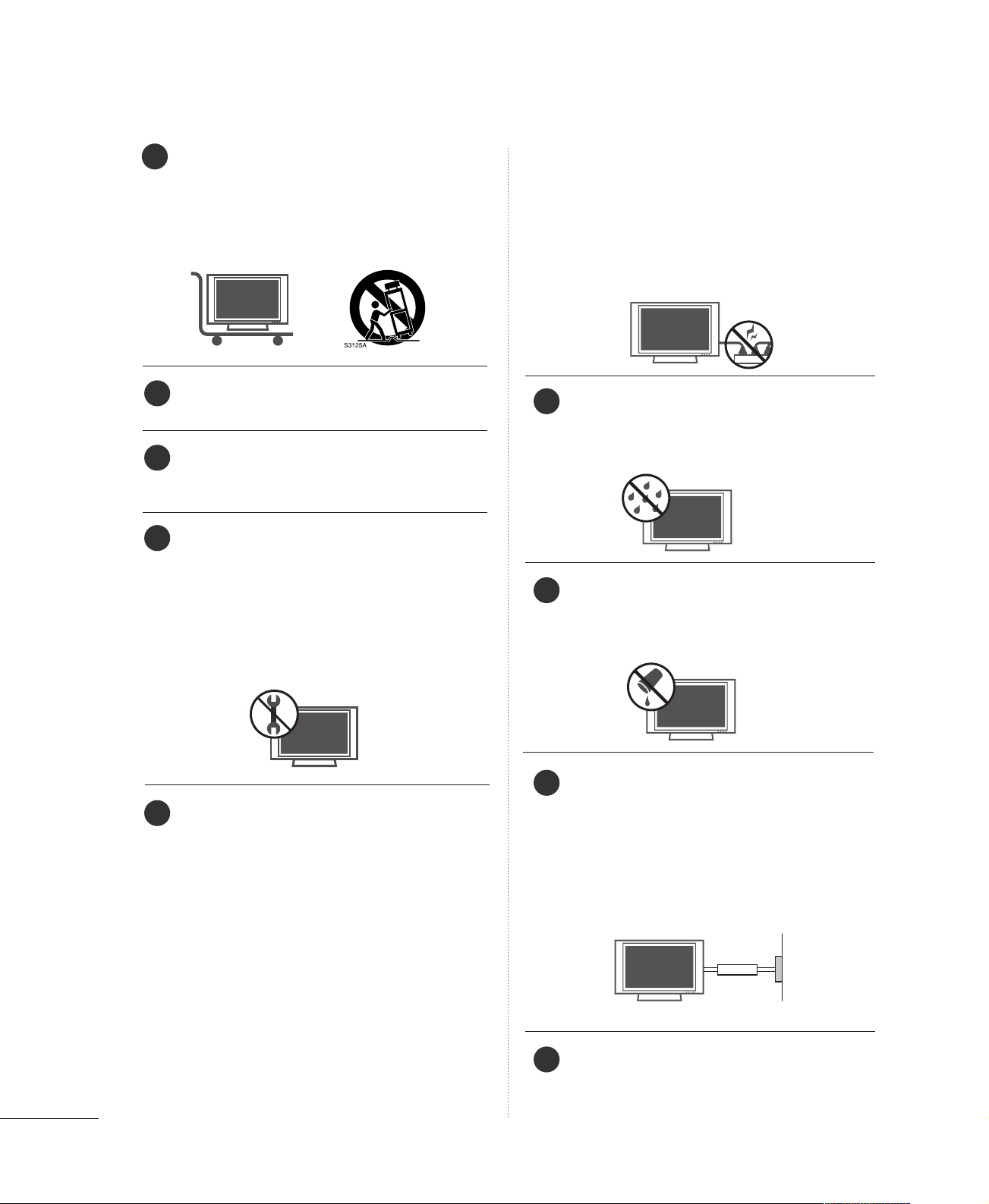
Use only with the cart, stand, tripod, bracket,
or table specified by the manufacturer, or sold
with the apparatus. When a cart is used, use
caution when moving the cart/apparatus
combination to avoid injury from tip-over.
Never touch this apparatus or antenna during
a thunder or lighting storm.
Do not allow a impact shock or any objects to
fall into the product, and do not drop onto the
screen with something.
Refer all servicing to qualified service personnel.
Servicing is required when the apparatus has
been damaged in any way, such as power-supply
cord or plug is damaged, liquid has been
spilled or objects have fallen into the apparatus,
the apparatus has exposed to rain or moisture,
does not operate normally, or has been
dropped.
CAUTION concerning the Power Cord :
Most appliances recommend they be placed
upon a dedicated circuit; that is, a single outlet
circuit which powers only that appliance and
has no additional outlets or branch circuits.
Check the specification page of this owner's
manual to be certain.
Do not overload wall outlets. Overloaded wall
outlets, loose or damaged wall outlets, extension
cords, frayed power cords, or damaged or
cracked wire insulation are dangerous. Any of
these conditions could result in electric shock
or fire. Periodically examine the cord of your
appliance, and if its appearance indicates damage or deterioration, unplug it, discontinue use
of the appliance, and have the cord replaced
with an exact replacement part by an authorized
servicer. Protect the power cord from physical
or mechanical abuse, such as being twisted,
kinked, pinched, closed in a door, or walked
upon. Pay particular attention to plugs, wall
outlets, and the point where the cord exits the
appliance.
Outdoor use marking :
WARNING - To reduce the risk of fire or elec-
tric shock, do not expose this appliance to rain
or moisture.
Wet Location Marking : Apparatus shall not be
exposed to dripping or splashing and no
objects filled with liquids, such as vases, shall
be placed on or over apparatus.
GGRROOUUNN DD IINNGG
Ensure that you connect the earth ground wire
to prevent possible electric shock. If grounding
methods are not possible, have a qualified
electrician install a separate circuit breaker.
Do not try to ground the unit by connecting it
to telephone wires, lightening rods, or gas pipes.
DDIISSCCOONNNN EECCTTIINNGG DDEEVVIICCEE FF RR OO MM MMAAII NNSS
Mains plug is the disconnecting device. The
plug must remain readily operable.
9
12
10
11
13
14
15
16
17
Power
Supply
Short-circuit
Breaker
Page 5
5
CONTENTS
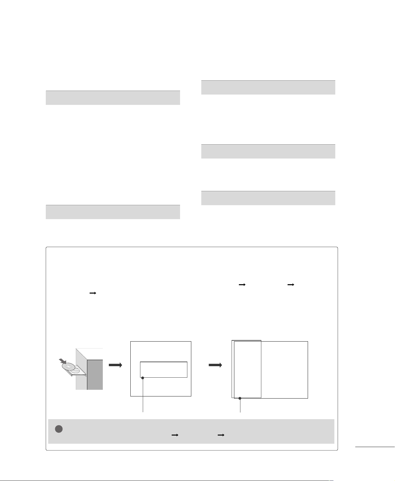
HOW TO USE THE OWNER'S MANUAL ON THE CD-ROM
To view the Owner's Manual on the CD-ROM, Adobe Acrobat Reader must be installed on your PC.
The “ACRORD" folder on the CD-ROM contains the installation programs for them.
If you want to install those programs, Open the “My Computer” Open the “LG” Open the
“ACRORD” double-click your language.
TO VIEW THE OWNER'S MANUAL ON THE CD-ROM
The Owner's Manual files are included in the supplied CD-ROM.
Load the supplied CD-ROM into the CD-ROM drive of your PC.
After a while, the web page of the CD-ROM will open automatically. (for Window only)
GG
If the web page does not appear automatically, open the Owner's Manual file directly.
Open the “My computer” Open the “LG” Open the “index.htm” file.
NOTE
!
When you select your product,
display the PDF file.
You can find the desired contents
easily using the bookmark.
WARNING / CAUTION
. . . . . . . . . . . . . . . . . . . . . . . . . . . .
2
SAFETY INSTRUCTIONS
. . . . . . . . . . . . . . . . . . . . . . . . . . 3
PREPARATION
Accessories
. . . . . . . . . . . . . . . . . . . . . . . . . . . . . . . . . . . . . . . . . . . . . . . . . . . . . .
6
Front Panel Information
. . . . . . . . . . . . . . . . . . . . . . . . . . . . . . . . . . . . . .
7
Back Panel Information
. . . . . . . . . . . . . . . . . . . . . . . . . . . . . . . . . . . . . .
8
Remote Control Functions
. . . . . . . . . . . . . . . . . . . . . . . . . . . . . . .
10
Stand Installation
. . . . . . . . . . . . . . . . . . . . . . . . . . . . . . . . . . . . . . . . . . . .
12
Attaching the TV to a Desk
. . . . . . . . . . . . . . . . . . . . . . . . . . . . . .
13
Back Cover for Wire Arrangement
. . . . . . . . . . . . . . . . . . . . .
14
Attaching the TV to a Wall
. . . . . . . . . . . . . . . . . . . . . . . . . . . . . . .
16
Desktop Pedestal Installation
. . . . . . . . . . . . . . . . . . . . . . . . . . . . 17
VESA Wall Mounting
. . . . . . . . . . . . . . . . . . . . . . . . . . . . . . . . . . . . . . . . 17
Antenna or Cable Connection
. . . . . . . . . . . . . . . . . . . . . . . . . .
18
EXTERNAL EQUIPMENT SETUP
HD Receiver Setup
. . . . . . . . . . . . . . . . . . . . . . . . . . . . . . . . . . . . . . . . . 19
DVD Setup
. . . . . . . . . . . . . . . . . . . . . . . . . . . . . . . . . . . . . . . . . . . . . . . . . . . . . 20
VCR Setup
. . . . . . . . . . . . . . . . . . . . . . . . . . . . . . . . . . . . . . . . . . . . . . . . . . . . . 21
PC Setup
. . . . . . . . . . . . . . . . . . . . . . . . . . . . . . . . . . . . . . . . . . . . . . . . . . . . . . . .
22
WATCHING TV
Turning On the TV
. . . . . . . . . . . . . . . . . . . . . . . . . . . . . . . . . . . . . . . . . .23
Channel Selection
. . . . . . . . . . . . . . . . . . . . . . . . . . . . . . . . . . . . . . . . . . . 23
Volume Adjustment
. . . . . . . . . . . . . . . . . . . . . . . . . . . . . . . . . . . . . . . . .
23
Channel Setup
. . . . . . . . . . . . . . . . . . . . . . . . . . . . . . . . . . . . . . . . . . . . . . . . 24
On-Screen Menus Selection
. . . . . . . . . . . . . . . . . . . . . . . . . . . . . 25
Entry Modes
. . . . . . . . . . . . . . . . . . . . . . . . . . . . . . . . . . . . . . . . . . . . . . . . . . .28
Photo List
. . . . . . . . . . . . . . . . . . . . . . . . . . . . . . . . . . . . . . . . . . . . . . . . . . . . . . . 29
Music List
. . . . . . . . . . . . . . . . . . . . . . . . . . . . . . . . . . . . . . . . . . . . . . . . . . . . . . . 31
APPENDIX
Troubleshooting
. . . . . . . . . . . . . . . . . . . . . . . . . . . . . . . . . . . . . . . . . . . . . .
33
Maintenance
. . . . . . . . . . . . . . . . . . . . . . . . . . . . . . . . . . . . . . . . . . . . . . . . . . .
34
Product Specifications
. . . . . . . . . . . . . . . . . . . . . . . . . . . . . . . . . . . . .
35
Open Source Software Notice
. . . . . . . . . . . . . . . . . . . . . . . . . . 36
MEDIAMEDIA
HOST HOST
Page 6
PREPARATION
6
PREPARATION
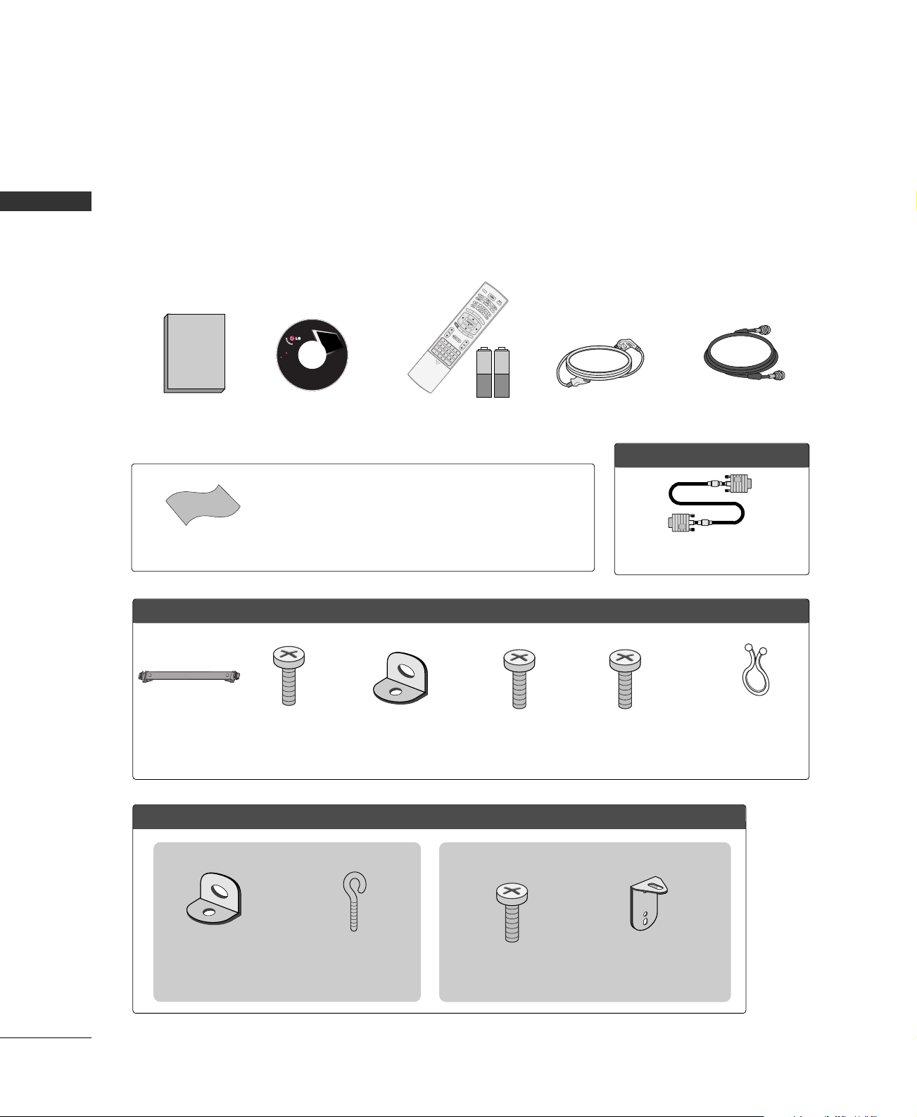
ACCESSORIES
Ensure that the following accessories are included with your product. If an accessory is missing, please contact the dealer where you purchased the product.
User must use shielded signal interface cables (D-sub 15 pin cable) with ferrite cores to maintain standard
compliance for the product.
For further information, see the the Owner's Manual files supplied CD-ROM.
OOppttiioonn EExxttrraass
FFoorr LLCCDD TTVV mmooddeellss
Cable
Management
4-Bolts for stand
assembly
(Refer to p.12)
1- Screw for
stand fixing
(Refer to p.13)
FFoorr PPllaassmmaa TTVV mmooddeellss
* Slightly wipe stained spot on the exterior only with the polishing cloth
for the product exterior if there is stain or fingerprint on surface of the
exterior.
* Do not wipe roughly when removing stain. Please be cautions of that
excessive pressure may cause scratch or discoloration.
Polishing Cloth
LCD TV PLASMA TV
Owner's Manual
http://www.lgusa.com
www.lg.ca
Copyright© 2007 LGE,
All Rights Reserved.
D-sub 15 pin Cable
1.5V 1.5V
Owner’s Manual Power Cord
75ohm Round Cable
Remote Control,
Batteries
APM
C
AUTO
D
E
MO
M/C EJECT
TV INPUT
STBSTB
MENU
BRIGHT +
BRIG
H
T -
TIMER
RATIO
SIM
P
LINK
BACKBACK
APM
CC
AUTO
DEMO
M/C EJECT
TV INPU
T
TV INPUT
STBSTB
MENU
BRIGHT +
BRIG
H
T -
TIMER
RATIO
SIM
P
LINK
BACKBACK
TV INPUT
STB
MENU
BRIGHT -
TIMER
RATIO
SIM
P
LINK
BACKBACK
PICTUREPICTURE
SOUNDSOUND
SAPSAP
CCCC
MARKMARK
USB EJECTUSB EJECT
MEDIA HOSTMEDIA HOST
MEDIA
HOSTMEDIA HOST
MEDIA HOST
CD Manual
(Refer to p.5)
2- TV Bracket
Bolts
(Refer to p.16)
2- TV Brackets,
2- Wall Brackets
(Refer to p.16)
For 60 inches
2- TV Bracket Bolts
(Refer to p.16)
2- TV Brackets,
2- Wall Brackets
(Refer to p.16)
2- Wall Brackets
(Refer to p.16)
2- Eye Bolts
(Refer to p.16)
For 42/50 inches
Twist Holder
Arrange the wires
with the twist holder.
Page 7

PREPARATION
7
FRONT PANEL INFORMATION
■
Here shown may be somewhat different from your TV.
■
NOTE: If your product has a protection tape attached, remove the tape.
And then wipe the product with a cloth (If a polishing cloth is included with your product, use it).
Plasma TV Model
POWER
Button
INPUT
Button
MENU
Button
ENTER
Button
VOLUME
(
FF,GG
)Buttons
CHANNEL
(
EE,DD
)Buttons
Power/Standby Indicator
Illuminates red in standby mode.
Illuminates green when the set is switched on.
Remote Control Sensor
LCD TV Model
CH
VOL
ENTER
MENU
INPUT
Remote Control Sensor
Intelligent Eye
Adjusts picture
according to the sur-
rounding conditions.
Power/Standby Indicator
Illuminates red in standby mode.
Illuminates green when the set is switched on.
CHCH
VOLVOL
ENTERENTER
MENUMENU
INPUTINPUT
CHANNEL
(
EE,DD
) Buttons
VOLUME
(
FF,GG
) Buttons
ENTER Button
MENU Button
INPUT Button
POWER Button
INPUT
MENU
ENTER
VOL
CH
Page 8
PREPARATION
8
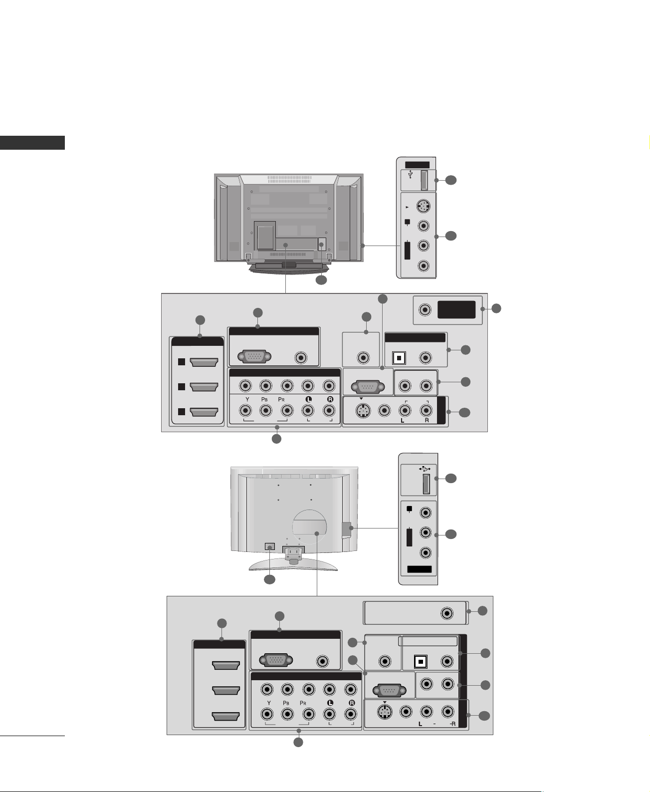
BACK PANEL INFORMATION
PREPARTION
■
Here shown may be somewhat different from your TV.
Plasma TV Model
LCD TV Model
AV IN 2
L/MONO
R
AUDIO
VIDEO
S-VIDEO
USB
RGB IN
COMPONENT IN
AUDIO
(RGB/DVI)
RGB(PC)
REMOTE
CONTROL IN
ANTENNA/
CABLE IN
1
2
RS-232C IN
(CONTROL & SERVICE)
VIDEO
AUDIO
VIDEO
AUDIO OUT
OPTICAL
COAXIAL
MONO
( )
AUDIO
S-VIDEO
DIGITAL AUDIO OUT
AV IN 1
R
HDMI/DVI IN
3
2
1
1
3
4
5
6
7
8
2
11
10
9
9
AV IN 2
L/MONO
R
AUDIO
VIDEO
USB IN
RGB IN
HDMI/DVI IN
COMPONENT IN
AUDIO
(RGB/DVI)
RGB(PC)
REMOTE
CONTROL IN
ANTENNA/
CABLE IN
1
1
2
2
3
RS-232C IN
(CONTROL & SERVICE)
VIDEO
AUDIO
VIDEO
AUDIO OUT
OPTICAL COAXIAL
MONO
( )
AUDIO
S-VIDEO
DIGITAL AUDIO OUT
AV IN 1
R
1
3
4
5
6
7
8
2
11
10
9
9
Page 9

PREPARATION
9
HDMI/DVI IN
Connect a HDMI signal to 1, 2 or 3.
Or DVI (VIDEO) signal to the 1, 2 or 3 port with a
DVI to HDMI cable.
COMPONENT IN
Connect a component video/audio device to these
jacks.
RGB (PC)
Connect the output from a PC.
AUDIO (RGB/DVI)
Connect the audio from a PC or DTV.
REMOTE CONTROL PORT
Connect your wired remote control.
RS-232C IN (CONTROL & SERVICE) PORT
Connect to the RS-232C port on a PC.
ANTENNA/CABLE IN
Connect over-the air signals to this jack.
Connect cable signals to this jack.
DIGITAL AUDIO OUT
Connect digital audio to various types of equipment.
Note: In standby mode, these ports do not work.
AUDIO OUT
Connect analog audio to various types of equipment.
AV (Audio/Video) IN 1/2
Connect audio/video output from an external
device to these jacks.
S-VIDEO
Connect S-Video out from an S-VIDEO device.
USB INPUT
Power Cord Socket
For operation with AC power.
Caution: Never attempt to operate the TV on DC
power.
1
2
3
4
5
6
7
8
9
10
11
Page 10
PREPARATION
10
PREPARATIONPREPARATION
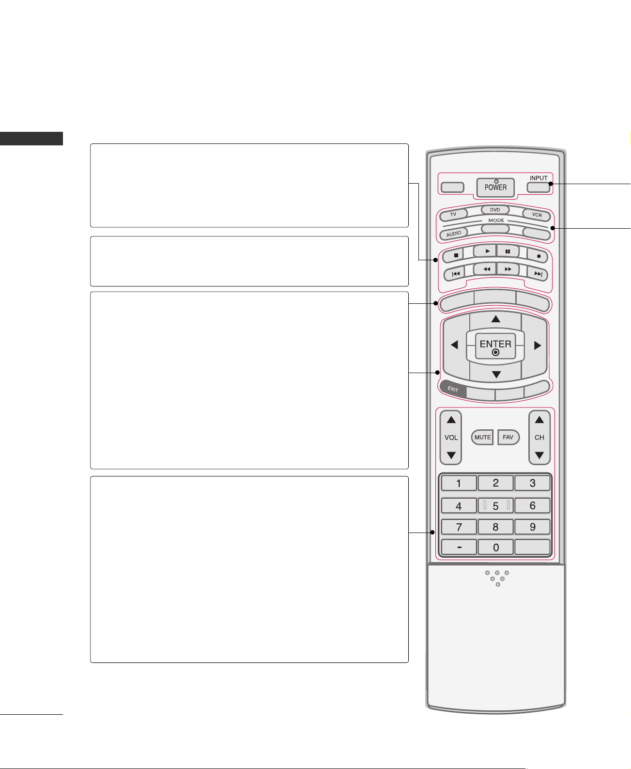
REMOTE CONTROL FUNCTIONS
When using the remote control, aim it at the remote control sensor on the TV.
APM
CC
AUTO DEMO
M/C EJECT
TV INPUTTV INPUT
STBSTB
MENU
BRIGHT +
BRIGHT -
TIMER
RATIO
SIMPLINK
BACKBACK
TV INPUT
STB
BACK
TV INPUT
STB
BACK
PICTURE
SOUND
SAP
CC
MARK
USB EJECT
MEDIA HOSTMEDIA HOST
MEDIA HOST
MEDIA HOST
MENU
BRIGHT +/-
THUMBSTICK
(Up/Down/Left
Right/ENTER)
EXIT
TIMER
RATIO
SIMPLINK
VOLUME UP
/DOWN
MUTE
FAV
CHANNEL
UP/DOWN
BACK
— (DASH)
Controls the mode.
Control video cassette recorders or DVD players.
Displays the main menu.
Adjust brightness on screen.
Navigate the on-screen menus and adjust the system set-
tings to your preference.
Clear all on-screen displays and return to TV viewing from
any menu.
Select the amount of time before your TV turns off automatically.
Change the aspect ratio.
See a list of AV devices connected to TV.
When you toggle this button, the SimpLink menu appears
at the screen.
Increase/decrease the sound level.
Switch the sound on or off.
Scroll through the programmed Favorite channels.
Select available channels.
Tune to the last channel viewed.
Used to enter a program number for multiple
program channels such as 2-1, 2-2, etc.
MEDIAMEDIA
HOST HOST
mode control
buttons
MEDIAMEDIAMEDIA
HOST HOST HOST
MEDIA
HOST
NUMBER button
VCR/DVD
buttons
Page 11

PREPARATION
11
TV INPUT
STB
BACK
PICTURE
SOUND
SAP
CC
MARK
USB EJECT
MEDIA HOST
Inside the Sliding Cover
PICTURE
SOUND
SAP
CC
MARK
USB EJECT
Adjust the factory preset picture depend
on the viewing environment.
Select the appropriate type of sound for
type of program.
Select MTS sound: Mono, Stereo, and SAP
analog mode. Change the audio language
DTV mode.
Select the Caption On/Off.
Enter the selected functions.
Remove the USB device.
Installing Batteries
■
Open the battery compartment cover on the
back side and install the batteries matching correct polarity (+with +,-with -).
■
Install two 1.5V AA batteries. Don’t mix old or
used batteries with new ones.
■
Close cover.
TV INPUT
STB
TV INPUT
STB
MEDIA HOST
MEDIA HOST
TV INPUT
STB
TV INPUT
STB
MEDIA HOST
MEDIA HOST
■
Use a remote control up to 7 meters distance and 30
degree (left/right) within the receiving unit scope.
■
Dispose of used batteries in a recycle bin to preserve environment.
Remote control effective range
POWER
TV INPUT
INPUT
MODE
MEDIAMEDIAMEDIA
HOST HOST HOST
MEDIA
HOST
Turns your TV or any other programmed equipment on or off, depending on the mode.
In AV 1-2, Component 1-2, RGB-PC, HDMI1, HDMI2 and HDMI3 input sources, screen returns to
the last TV channel.
External input modes rotate in regular sequence: Antenna, Cable, AV1-2, Component 1-2, RGB-PC,
HDMI1, HDMI2, and HDMI3 (AV 1-2, Component 1-2, RGB-PC, HDMI1, HDMI2, and HDMI3
input sources are linked automatically, only if these are connected ).
Select the remote operating mode: TV, DVD, VCR, AUDIO, or STB.
* If the mode of another product is selected, a button on the remote control which is not used for
the selected product can control the TV.
Enter to the mode.
MEDIAMEDIA
HOST HOST
PICTURE
MARK
SOUND
USB EJECT
SAP
BACK
CC
TV INPUT
STB
ME
D
IA
HOST
MENU
BRIG
T -
H
H
T +
BRIG
K
TV INPUT
STB
ME
D
IA
HOST
MENU
BRIG
T -
H
H
T +
BRIG
LINK
P
SIM
TIMER
RATIO
Page 12

PREPARATION
12
PREPARATIONPREPARATION
STAND INSTALLATION (Only 37LB5D)
Carefully place the product screen side down on
a cushioned surface that will protect product and
screen from damage.
Assemble the product stand with the product as
shown.
Install the 4 bolts securely, in the back of the
product in the holes provided.
1
2
3
Page 13

PREPARATION
13
ATTACHING THE TV TO A DESK (Only 32LB9D model)
1-Screw
(provided as parts
of the product)
Stand
Desk
The TV must be attached to a desk so it cannot be pulled in a forward/backward direction, potentially causing
injury or damaging the product.
GG
This apparatus must be securely attached to the floor/wall per installation instructions. Tipping, shaking,
or rocking the machine may cause injury/death.
WARNING
Page 14

PREPARATION
14
PREPARATIONPREPARATION
BACK COVER FOR WIRE ARRANGEMENT
Plasma TV Model
Hold the CABLE MANAGEMENT with both hands and pull it backward as shown.
Connect the cables as necessary.
To connect an additional equipment, see the EXTERNAL EQUIPMENT SETUP section.
1
2
Install the CABLE MANAGEMENT as shown.
3
■
Here shown may be somewhat different from your TV.
CABLE MANAGEMENT
Page 15

PREPARATION
15
LCD TV Model
Connect the cables as necessary.
To connect an additional equipment, see the
EXTERNAL EQUIPMENT SETUP section.
Install the CABLE MANAGEMENT as shown.
(Insert it as pushing the loops on the both sides
of the cable management.)
GG
Do not hold the CABLE MANAGEMENT when moving
the product.
- If the product is dropped, you may be injured or the
product may be broken.
NOTE
!
1
2
Bundle the cables using the supplied TWIST
HOLDER.
3
How to remove the CABLE MANAGEMENT
GG
Hold the CABLE MANAGEMENT with both hands and
pull it out.
(Pull it out as holding the loops on the both sides of the
cable management.)
CABLE MANAGEMENT
TWIST HOLDER
Page 16

PREPARATION
16
PREPARATIONPREPARATION
ATTACHING THE TV TO A WALL
We recommend that you set up the TV close to a wall so it cannot fall over if pushed backwards.
Additionally, we recommend that the TV be attached to a wall so it cannot be pulled in a forward direction,
potentially causing injury or damaging the product.
Caution: Please make sure that children don’t climb on or hang from the TV.
Plasma TV Model LCD TV Model
■
Insert the eye-bolts (or TV brackets and bolts) to tighten the product to the wall as shown in the picture.
*If your product has the bolts in the eye-bolts position before inserting the eye-bolts, loosen the bolts.
Secure the wall brackets with the bolts (not provided as parts of the product, must purchase separately) to
the wall. Match the height of the bracket that is mounted on the wall to the holes in the product.
Ensure the eye-bolts or brackets are tightened securely.
■
Use a sturdy rope (not provided as parts of the product, must purchase separately) to tie the product. It is safer to tie the rope so it
becomes horizontal between the wall and the product.
■
Here shown may be somewhat different from your TV.
42/50 inches 60 inches
Page 17

PREPARATION
17
DESKTOP PEDESTAL INSTALLATION
VESA WALL MOUNTING
For proper ventilation, allow a clearance of 4inches on all four sides from the wall.
GG
Ensure adequate ventilation by following the clearance recommendations.
CAUTION
Plasma TV Model LCD TV Model
This product accepts a VESA-compliant mounting interface pad. (optional)
There 4 threaded holes are available for attaching the bracket.
GG
Screw length needed depends on the wall mount used. For further information, refer to the VESA
Wall Mounting Instruction Guide.
NOTE
!
Plasma TV Model LCD TV Model
4 inches
4 inches
4 inches
4 inches
4 inches
4 inches
4 inches
4 inches
R
R
600 mm
400 mm
100 mm
200 mm
Page 18

PREPARATION
18
PREPARATIONPREPARATION
ANTENNA OR CABLE CONNECTION
1. Antenna (Analog or Digital)
Wall Antenna Socket or Outdoor Antenna without a Cable Box
Connections.
For optimum picture quality, adjust antenna direction if needed.
2. Cable
Wa ll
Antenna
Socket
Outdoor
Antenna
(VHF, UHF)
Cable TV
Wall Jack
Multi-family Dwellings/Apartments
(Connect to wall antenna socket)
RF Coaxial Wire (75 ohm)
RF Coaxial Wire (75 ohm)
Single-family Dwellings /Houses
(Connect to wall jack for outdoor antenna)
Be careful not to bend the bronze wire
when connecting the antenna.
Copper Wire
ANTENNA/
CABLE IN
R
ANTENNA/
CABLE IN
R
ANTENNA/
CABLE IN
R
ANTENNA/
CABLE IN
R
GG
The TV will let you know when the analog, cable, and digital channel scans are complete.
NOTE
!
■
To improve the picture quality in a poor signal area, please purchase a signal amplifier and install properly.
■
If the antenna needs to be split for two TV’s, install a 2-Way Signal Splitter.
■
If the antenna is not installed properly, contact your dealer for assistance.
Antenna
UHF
Signal
Amplifier
VHF
3. Using both cable and antenna
Cable TV
Wall Jack
Antenna
RF Coaxial Wire (75 ohm)
RF Coaxial Wire (75 ohm)
Diplexer
(Signal
Combiner)
R
R
Page 19

EXTERNAL EQUIPMENT SETUP
19
EXTERNAL EQUIPMENT SETUP
HD RECEIVER SETUP
This TV can receive Digital Over-the-air/Cable signals without an external digital set-top box. However, if you do
receive digital signals from a digital set-top box or other digital external device, refer to the figure as shown below.
RGB IN
AUDIO
(RGB/DVI)
RGB(PC)
RE
CONT
RS
(CONTR
COMPONENT IN
1
2
VIDEO
AUDIO
Y L RPB PR
( )
S-VIDEO
When connecting Component cable
1 2
1. How to connect
Connect the video outputs (Y, P
B, P
R
)
of the digital set
top box to the
CC OOMMPPOONNEE NNTT IINN VVIIDDEE OO 11
jacks on
the set. Match the jack colors (Y = green, P
B
= blue, and
P
R
= red).
Connect the audio output of the digital set-top box to
the
CC OOMMPPOONNEE NNTT IINN AAUUDD IIOO 11
jacks on the set.
2
1
2. How to use
■
Turn on the digital set-top box.
(
Refer to the owner’s manual for the digital set-top box. operation
)
■
Select
CC oo mmpp oonneenn tt 11
input source by using the
IINN PPUUTT
button on the remote control.
■
If connected to
CC OO MMPP OONNEENN TT IINN 22
input, select
CC oo mmppoo nneenntt 22
input source.
■
To prevent the equipment damage, never plug in any power cords until you have finished connecting all equipment.
■
This part of EXTERNAL EQUIPMENT SETUP mainly use picture for Plasma TV model.
Y, C
B/PB
, CR/P
R
Horizontal Vertical
Frequency(KHz)Frequency(Hz
)
15.73 59.94
15.73 60.00
31.47 59.94
31.50 60.00
44.96 59.94
45.00 60.00
33.72 59.94
33.75 60.00
26.97 23.976
27.00 24.00
33.71 29.97
33.75 30.00
67.432 59.94
67.50 60.00
Resolution
720x480i
720x480p
1280x720p
1920x1080i
1920x1080p
Signal
480i
480p
720p
10 8 0 i
10 8 0 p
Component 1/2
Yes
Yes
Yes
Yes
Yes
HDMI1/2/3
No
Yes
Yes
Yes
Yes
Page 20

EXTERNAL EQUIPMENT SETUP
20
EXTERNAL EQUIPMENT SETUP
When connecting Component cable
RS-
(CONTRO
COMPONENT IN
1
2
VIDEO
AUDIO
Y L RPB PR
( )
S-VIDEO
Connect the video outputs (Y, P
B, PR
)
of the DVD to the
CC OOMMPPOONNEE NNTT IINN VVIIDD EEOO11
jacks on the set.
Match the jack colors (Y = green, P
B = blue, and P
R = red
)
.
Connect the audio outputs of the DVD to the
CC OOMMPPOONNEENNTT IINN AAUUDDII OO11
jacks on the set.
1. How to connect
2. How to use
■
Turn on the DVD player, insert a DVD.
■
Select
CC oo mmpp oonneenn tt 11
input source by using the
IINN PPUUTT
button on the remote control.
■
If connected to
CC OOMMPPOONNEENNTT IINN 22
input, select
CC oo mmppoo nneenntt 22
input source.
■
Refer to the DVD player's manual for operating instructions.
2
1
1 2
DVD SETUP
RGB IN
COMPONENT IN
AUDIO
(RGB/DVI
RGB(PC)
1
2
VIDEO
A
HDMI/DVI IN
( )
3
2
1
HDMI-DVD OUTPUT
When connecting HDMI cable
Connect the HDMI output of the DVD to the
HHDDMMII//DDVVII IINN 11, 22
, or 33jack on the set.
No separated audio connection is necessary.
HDMI supports both audio and video.
1. How to connect
2. How to use
■
Select
HHDDMMII11,HHDDMMII22
,or
HHDDMMII33
input source by using
the
IINN PPUUTT
button on the remote control.
■
Refer to the DVD player's manual for operating instructions.
■
If the DVD does not support Auto HDMI, you need to set
the output resolution appropriately.
2
1
1
Page 21

EXTERNAL EQUIPMENT SETUP
21
VCR SETUP
GG
Do not connect to both Video
and S-Video at the same time. In
the event that you connect both
Video and the S-Video cables,
only the S-Video will work.
CAUTION
When connecting with a RCA cable
GG
The picture quality is improved: compared to normal
composite (RCA cable) input.
NOTE
!
B/DVI)
REMOTE
CONTROL IN
RS-232C IN
(CONTROL & SERVICE)
OPTICAL COAXIAL
DIGITAL AUDIO OUT
AUDIO OUT
ANTE
CAB
AUDIO
AV IN 1
VIDEO
MONO
( )
S-VIDEO
AUDIO
L R
S-VIDEO VIDEO
OUTPUT
SWITCH
ANT IN
ANT OUT
( )
REMOTE
CONTROL IN
RS-232C IN
(CONTROL & SERVICE)
OPTICAL COAXIAL
DIGITAL AUDIO OUT
AUDIO OUT
ANT
CAB
AUDIO
AV IN 1
VIDEO
MONO
( )
S-VIDEO
AUDIO
L R
S-VIDEO VIDEO
OUTPUT
SWITCH
ANT IN
ANT OUT
( )
Connect the
AAUUDDIIOO/VVIIDD EEOO
jacks between TV and
VCR. Match the jack colors (Video = yellow, Audio Left
= white, and Audio Right = red)
1. How to connect
2. How to use
■
Insert a video tape into the VCR and press PLAY on the
VCR. (Refer to the VCR owner’s manual.
)
■
Select
AAVV11
input source by using the
IINN PPUUTT
button on
the remote control.
■
If connected to
AAVV IINN22
, select
AAVV22
input source.
When connecting with an S-Video cable
Connect the S-VIDEO output of the VCR to the
SS --VVIIDDEEOO
input on the set.
Connect the audio outputs of the VCR to the
AAUUDDIIOO
input jacks on the set.
1. How to connect
2. How to use
■
Insert a video tape into the VCR and press PLAY on the VCR.
(
Refer to the VCR owner’s manual.
)
■
Select
AAVV11
input source by using the
IINN PPUUTT
button on the
remote control.
■
If connected to
AAVV IINN22
, select
AAVV22
input source.
1
2
1
GG
If you have a mono VCR, connect the audio cable from the VCR to the
AAUUDDII OO LL // MMOONNOO
jack of the set.
NOTE
!
1
1
2
Page 22

EXTERNAL EQUIPMENT SETUP
22
EXTERNAL EQUIPMENT SETUP
PC SETUP
When connecting HDMI to DVI cable
( )
AUDIO O
VIDEO
MONO
( )
AUDI
S-VIDEO
COMPONENT IN
REMOTE
CONTROL IN
1
2
RS-232C IN
(CONTROL & SERVICE)
VIDEO
AUDIO
OPTICAL CO
DIGITAL AU
HDMI/DVI IN
RGB IN
AUDIO
(RGB/DVI)
L R
DVI-PC OUTPUT
RGB(PC)
3
2
1
1
2
Connect the DVI output of the PC to the
HHDDMMII//DDVVII
IINN11, 22
or
33
jack on the set.
Connect the PC audio output to the
AAUUDDIIOO
((
RRGGBB//DDVVII
))
jack on the set.
1. How to connect
2. How to use
■
Turn on the PC and the TV.
■
Select
HHDDMMII11,HHDDMMII22 orHHDDMMII33
input source by using
the
IINN PPUUTT
button on the remote control.
2
1
When connecting D-sub 15pin cable
V
( )
S-VIDEO
COMPONENT IN
REMOTE
CONTROL IN
1
2
RS-232C
(CONTROL & SE
VIDEO
AUDIO
RGB IN
AUDIO
(RGB/DVI)
RGB(PC)
RGB OUTPUT AUDIO
Connect the RGB output of the PC to the
RRGGBB ((PP CC
))
jack on the set.
Connect the PC audio output to the
AAUUDDIIOO
((
RRGGBB//DDVVII
))
jack on the set.
1. How to connect
2. How to use
■
Turn on the PC and the TV.
■
Select
RRGGBB-- PPCC
input source by using the
IINN PPUUTT
button
on the remote control.
2
1
1
2
Supported Display Specifications
Horizontal Vertical
Frequency(KHz)Frequency(Hz
)
31.469 70.08
31.469 70.08
31.469 59.94
37.879 60.31
48.363 60.00
47.776 59.87
47.740 59.799
47.130 59.65
Resolution
720x400
1360x768
640x350
640x480
800x600
1024x768
1280x768
1366x768
RGB-PC, HDMI-PC
* RGB-PC mode only
* LCD TV only
Page 23

WATCHING TV
23
TURNING ON THE TV
WATCHING TV
NOTE
!
GG
If you intend to be away on vacation, disconnect the power plug from the wall power outlet.
First, connect power cord correctly.
At this moment, the TV switches to standby mode.
■
In standby mode to turn TV on, press the ,
IINNPPUUTT,CCHH ((
DD
or
EE
))
button on the TV or press the
PPOOWWEERR, IINNPPUUTT, TTVV IINNPPUUTT, CCHH((
DD
or
EE
)), NNuummbbeerr ((00~99))
button on the remote control.
Select the viewing source by using the
TTVV IINNPPUUTT, IINNPPUUTT
button on the
remote control.
■
This TV is programmed to remember which power state it was last set
to, even if the power cord is out.
When finished using the TV, press the
PPOOWWEERR
button on the remote
control. The TV reverts to standby mode.
TV INPUTTV INPUT
INPUT
TV INPUT
STB
PICTUREPICTUREPICTURE
SOUNDSOUND
SAPSAP
CCCC
MARKMARK
USB EJECTUSB EJECT
BACKBACK
MEDIA HOST
1
2
3
TV INPUT
STB
TIMER
RATIO
SIMP
PICTUREPICTUREPICTURE
SOUNDSOUND
SAPSAP
CCCC
BACKBACK
TV INPUT
STB
BACK
PICTURE
SAP
CC
TV INPUT
STB
BACK
PICTURE
SOUND
CC
TV INPUT
STB
BACK
PICTURE
SOUND
SAP
TV INPUT
SOUND
MEDIA HOST
MEDIA HOST
MEDIA HOST
MEDIA HOST
Press the
CCHH ((
DD
or
EE
))
or
NNUUMMBBEERR
buttons to select a channel number.
1
VOLUME ADJUSTMENT
CHANNEL SELECTION
Press the
VVOOLL ((
DD
or
EE
))
button to adjust the volume.
If you want to switch the sound off, press the
MMUUTTEE
button.
You can cancel the Mute function by pressing the
MMUUTTEE
or
VVOOLL ((
DD
or
EE
))
button.
TV INPUT
STB
TIMER
RATIO
SIMPLINK
TV INPUT
STB
TV INPUT
STB
TV INPUT
STB
TV INPUT
STB
MEDIA HOST
MEDIA HOST
MEDIA HOST
MEDIA HOST
MEDIA HOST
Adjust the volume to suit your personal preference.
1
2
3
Page 24

WATCHING TV
24
CHANNEL SETUP
Press the
MM EENNUU
button and then use
DD
or
EE
button
to select the
SS EETTUUPP
menu.
Press the
GG
button and then use
DD
or
EE
button to
select
AAuu ttoo TTuu nniinngg
.
Press the
EENN TT EERR
button to begin the channel search.
Allow
AAuu ttoo TTuu nniinngg
to complete the channel search
cycle for
AANN TT EENN NNAA
and
CC AABBLL EE
.
Automatically finds all channels available through antenna
or cable inputs, and stores them in memory on the channel
list.
Run Auto Tuning again after any Antenna/Cable connection
changes.
A password is required to gain access to Auto Tuning menu
if the Lock System is turned on.
2
3
1
1
2
3
TV INPUTTV INPUT
STBSTB
BRIGHT +
BRIGHT -
TIMER
RATIO
SIMPLINK
MENU
TV INPUT
STB
TV INPUT
STB
TV INPUT
STB
TV INPUT
STB
TV INPUT
MEDIA HOSTMEDIA HOST
MEDIA HOST
MEDIA HOST
MEDIA HOST
MEDIA HOST
Auto Scan (Auto Tuning)
Auto Tuning
G
Manual Tuning
Channel Edit
Selection ( Gor ) leads you to
the Auto Tuning screen.
Auto Tuning
Manual Tuning
Channel Edit
Selection ( Gor ) leads
you to the Auto Tuning
screen.
NOTE
!
DTV (Digital DTV antenna)
TV (Analog TV antenna)
CADTV (Digital CADTV cable)
CATV (Analog CATV cable)
Processing Auto Tuning...
DTV Ch.23
Found Channel(s): 16
Press to stop the current
scan and start ANALOG
ANTENNA channel scan.
MENU Prev
Next
Auto Tuning
Manual Tuning
Channel Edit
Page 25

WATCHING TV
25
ON-SCREEN MENUS SELECTION
Press the
MMEENNUU
button and then use
DD
or
EE
button to select the each menu.
Press the
GG
button and then use
DD EE FF GG
button to display the available menus.
Your TV's OSD (On Screen Display)may differ slightly from what is shown in this manual.
2
1
■
All available TV channels are searched and stored
automatically.
■
User can do manual channel selection and add or
delete individual channels.
■
You can add or delete in the channel list.
Channel Edit
Manual Tuning
Auto Tuning
■
Select the preset value in the Picture Mode menu
based on the program category: Intelligent Eye (LCD
TV Only), Dynamic, Standard, Mild, User1, User2.
■
Choose one of three automatic color adjustments
: Cool, Medium, Warm, User
■
It is LG Electronic’s unique picture improving technology to display a real HD source through an
advanced digital signal processing algorithm.
■
Select Auto or Manual (XD Contrast, XD Color, XD Noise).
■
Cinema 3:2 Mode (On, Off)
Set up the TV for the best picture appearance for
viewing movies.
■
Black Level (Low, High)
Adjusting the contrast and the brightness of the
screen using the black level of the screen.
■
Select the desired picture format.
: Set by program, 4:3, 16:9, Zoom1, Zoom2, Just Scan.
■
Use to quickly reset all the Picture menu options to
their original factory preset values.
■
Adjust the screen Resolution, Position, Size, Phase,
Reset.
XD
Advanced
Picture Reset
Color Temperature
Picture Mode
SETUP
PICTURE
Auto Tuning
Manual Tuning
Channel Edit
Picture Mode : User1
Color Temperature : Cool
XD
Advanced
Aspect Ratio : 16:9
Picture Reset
Screen
Aspect Ratio
Screen
Page 26

WATCHING TV
26
WATCHING TV
AUDIO
Sound Mode : Standard
Auto Volume : On
Balance : 0
TV Speaker : On
■
Sound Mode lets you enjoy the best sound without any special adjustment.
: Standard, Music, Movie, Sports and User
■
Scans for changes in sound levels during commercials, then adjusts the sound to match the specified
audio level.
■
Adjust the left/right sound of speaker.
■
Turn the TV speaker On or off.
Balance
TV Speaker
Auto Volume
Sound Mode
TIME
Clo ck : Oct 19, 2006, 03:44 AM
Off Time : Off
On Time : Off
Sleep Time : Off
Auto Sleep : Off
■
Auto: The time is set automatically from a digital
channel signal.
Select your viewing area time zone.
Select Auto, Off, On depending on whether or
not your viewing area observes Daylight Saving
time.
■
Manual: Set the clock manually.
■
Select On or Off.
■
Select On or Off.
■
Select the amount of time before your TV turns off
automatically: Off, 10, 20,30, 60, 90, 120, 180,
240 .
■
TV will be automatically turned off, in case of no signal for 10 minutes.
Off Time
On Time
Sleep Time
Clock
Auto Sleep
Page 27

WATCHING TV
27
■
Select On or Off.
■
Change the password.
■
Select a channel number that you wish to block.
■
Blocks movies according to the movie ratings limits
specified.
■
Prevents children from watching certain children's
TV programs, according to the ratings limit set.
■
Based on the ratings, blocks certain TV programs
that you and your family do not want to view.
■
Selecting canadian english language rating system.
■
Selecting canadian french language rating system.
■
Enables you to select a source to block from the
external source devices you have hooked up.
Block Channel
Movie Rating
TV Rating-Children
TV Rating-General
TV Rating-English
TV Rating-French
Input Block
Set Password
Lock System
For USA
OPTION
LOCK
Language : English
Input Label
SimpLink : Off
Key Lock : Off
Caption : Off
ISM Method : Orbiter
Low Power : Off
Set ID : 1
Lock System : Off
Set Password
Block Channel
Movie Rating
TV Rating-Children
TV Rating-General
Input Block
For Canada
Lock System : Off
Set Password
Block Channel
TV Rating-English
TV Rating-French
Input Block
■
Select your desired language for on screen menus
: English, Spanish, French.
■
Set a label to each input source.
■
Control and play other AV devices connected to the
TV through HDMI cable without additional cables
and settings.
■
This feature can be used to prevent unauthorized
viewing by locking out the front panel controls.
■
Mode: When selecting Off, Submenus for Analog,
DTV, and Digital Option become disabled.
■
Analog: CC1~ CC4 , Text1~ Text4.
■
Digital: Service1~ Service6
■
Digital Option: Customize the DTV/CADTV captions
that appear on your screen.
■
Use it to minimize any fixed image on the screen.
: Normal, Orbiter, Inversion, White Wash.
■
Reduces the plasma display power consumption.
■
Choose the desired TV ID number.
SimpLink
key Lock
ISM Method
Low Power
Caption
Input Label
Language
Set ID
Plasma TV model only
Page 28

MEDIA HOST
28
ENTRY MODES
MEDIAMEDIA
HOST HOST
When you connect a USB device or press the button, this screen is
displayed, automatically.
In USB device, you can not add a new folder or delete the existing folder.
MEDIAMEDIA HOST HOST
Press the
DD
or EEbutton to select the desired item.
Press the
EENNTTEERR
button to move to
PPhhoottoo LLiisstt orMMuussiicc LLiisstt
of
USB device.
Press the
UUSSBB EEJJEECCTT
button of remote control before removing
the USB device.
1
2
NOTE
!
3
BACK
PICTUREPICTURE
SOUNDSOUND
SAPSAP
MARKMARK
USB EJECTUSB EJECT
CCCC
Media Host Menu
GG
Press the
UUSSBB EEJJEECCTT
button of remote control
before removing the USB device.
GG
Only a USB storage device is recognizable.
GG
If the USB storage device is connected through a
USB hub, the device is not recognizable.
GG
A USB storage device using an automatic recognition program may not be recognized.
GG
A USB storage device which uses its own driver
may not be recognized.
GG
In case of a card reader, up to four memory cards
are concurrently recognizable.
GG
The recognition speed of a USB storage device
may depend on each device.
GG
Please do not turn off the TV or unplug the USB
device when the connected USB storage device is
working. When such device is suddenly separated or unplugged, the stored files or the USB storage device may be damaged. To unplug the USB
storage device, please press the
UUSSBB EEJJEECCTT
button on the remote control, and then unplug it
safely.
GG
Please do not connect the USB storage device
which was artificially maneuvered on the PC. The
device may cause the product to malfunction or
fail to be played. Never forget to use only a USB
storage device which has normal music files or
image files.
GG
Please use only a USB storage device which was
formatted as a FAT or a NTFS file system provided
with the Windows operating system. In case of a
storage device formatted as a different utility program which is not supported by Windows, it may
not be recognized.
GG
In case of a hard disk drive (HDD) formatted as
NTFS, writing and deletion are not allowable.
GG
Please connect power to a USB storage device
which requires an external power supply. If not,
the device may not be recognized.
GG
Please connect a USB storage device with cable is
offered by USB maker. If connected with cable is
not offered by USB maker or an excessively long
cable, the device may not be recognized.
GG
Some USB storage devices may not be supported
or operated smoothly.
GG
If the name of a folder or file is too long, it will not
be displayed or recognized.
1 2
3
Page 29

MEDIA HOST
29
PHOTO LIST
Screen Components
Current page/Total pages
Total number of marked thumbnail
photos
Corresponding buttons
on the remote control
Usable USB memory
It’s available to playback the photo file(*.jpg) in the USB device.
The On Screen Display may be different from your set. Images are an example to assist with the TV operation.
1
2
3
4
4
Photo Selection and PopUp Menu
As shown, up to 15 thumbnail photos are listed per page.
Use the
CC HH
DD
or
EE
button to navigate in the thumb-
nail photo page.
Use the
MM AA RR KK
button to mark or unmark a photo.
When one or more photos are marked, you can view
individual photos or a slide show of the marked photos.
If no photos are marked, you can view all photos individually or all photos in the folder in a slide show.
Use
DD EE
FF GG
button to navigate the appropriate
thumbnail photos, then press the
EENN TTEERR
button to
show the PopUp menu.
Repeatedly, press
EEXX IITT
button to return to TV viewing
or press the button to return to the Media Host
menu.
MEDIAMEDIA HOST HOST
1
2
GG
VViieeww
: Display the selected item.
GG
MMaarrkk AAllll
: Mark all photos on the screen.
GG
DDeelleettee
: Delete the selected photo item.
GG
CCaanncceell
: Close the pop-up menu.
3
4
1 2
3
32
1
Page 30

MEDIA HOST
30
MEDIAMEDIA
HOST HOST
Set up the menu in Full-Sized Screen
You can change the settings to display photos stored on a
USB device, on a full-sized screen.
Detailed operations are available on full-sized photo view
screen.
The aspect ratio of a photo may change the size
of the photo displayed on the screen in full size.
Use the
CC HH
DD
or
EE
button to navigate the thumbnail
photo page.
Use
DD EE
FF GG
button to navigate the appropriate
thumbnail photos, then press the
EENN TTEERR
button to
show the PopUp menu.
Use
DD
or EEbutton to Move to the
VViieeww
menu, then
press the
EENN TTEERR
button.
The selected photo is displayed in full size.
2
1
4
3
1 2 3
4
GG
SS ll ii ddee SShhooww
: When no picture is selected, all photos in
the current folder are displayed during slide show. When
selected, the selected photos are displayed during slide
show. To start slide show, press
EENN TTEERR
button on
■ Set the time interval of the slide show in
OOpp ttiioo nn
.
■ A slide show continues for a maximum of 4 hours.
After 4 hours, the slide show will end and go to TV
mode or external input mode.
GG
BBGG MM
: Listen to music while viewing photos in full size.
To start BGM, press
EENN TTEERR
button on .
■ Set the BGM device and album in
OOpp ttiioo nn
.
GG
((RRoo ttaattee))
: Rotate photos.
■ Rotates the photo 90°, 18 0 °, 270 °,360° clockwise
upon
EENN TTEERR
button on
((RRoo ttaattee))
.
GG
DDeelleettee
: Delete photos. Use FFor GGbutton to select
DDeelleettee
and press
EENN TTEERR
button.
GG
OOpp ttiioo nn
: Set values for
SS ll ii ddee SS ppee eedd
and
MM uuss ii cc ff oolldd--
ee rr
. Use
FF
or GGbutton to select
OOpp ttiioo nn
and press
EENN TTEERR
button.
■
Use
FF
or
GG
button and
EENNTTEERR
button to set values.
Then go to and press
EENNTTEERR
to save the settings.
■
You cannot change
MMuussiicc FFoollddeerr
while BGM is playing.
Page 31

MEDIA HOST
31
GG
HHiidd ee
: Hide the menu on the full-sized screen. Use
FF
or
GG
button to select
HHiidd ee
and press
EENN TTEERR
button.
■
To see the menu again on the full-sized screen,
press
EENN TTEERR
button to display.
Use
DD EE
FF GG
button to select the previous or next
photo.
Use
DD EE
FF GG
button to select and control the menu
on the full-sized screen.
Use
EEXX IITT
button to go back to the photo list from
the full-sized screen.
Repeatedly, press
EEXX IITT
button to return to TV viewing or press button to return to the Media Host
menu.
MEDIAMEDIA HOST HOST
NOTE
!
GG
If it is Progressive JPEG format, some
photos may be not decorded.
5
6
7
Purchased music files(*.MP3) may contain copyright restrictions. Playback of these files may not be supported
by this model.
Music file on your USB device can be played by this unit.
The On Screen Display may be different from your set. Images are an example to assist with the TV operation.
Screen Components
MUSIC LIST
Current page/Total pages
Total number of marked musics
Current playing time/Total play-
ing time
Corresponding buttons on the
remote control
Usable USB memory
1
2
3
4
5
5
432
1
Page 32

MEDIA HOST
32
MEDIAMEDIA
HOST HOST
Use the
CC HH
DD
or
EE
button to navigate in the music
titles page.
Use
MM AA RR KK
button to mark or unmark a music. When
one or more music files are marked, the marked musics
will be played in sequence. For example, if you want to
listen to only one music repeatedly, just mark the music
only and play it. If no music is marked, all the music in
the folder will be played in sequence.
Use
DD EE
button to navigate the appropriate musics,
then press the
EENN TTEERR
button to show up the pop-up
menu.
Repeatedly, press
EEXX IITT
button to return to TV viewing
or press button to return to the Media Host
menu.
■
If you don't press any button for a while during the
playing, the play information box (as shown in the
below) will float as a screen saver.
■
The ‘Screen Saver’?
Screen saver is to prevent screen pixel damage due to
an fixed image remaining on the screen for a extended period of time.
MEDIAMEDIA HOST HOST
Music Selection and PopUp Menu
As shown , up to 8 music titles are listed per page.
NOTE
!
GG
When music is playing, is displayed in front of the music title.
GG
A damaged or corrupted music
does not play but displays 00:00 in
playtime.
GG
A music downloaded from a paid
service with copyright protection
does not start but displays inappropriate information in playtime.
GG
If you press
EENNTTEERR
,
,
EEXXIITT
buttons, screen saver is stopped.
GG
The
,,,,
buttons on the remote control are
also available in this mode.
GG
It’s not available to play MP3 file
under 16Kbyte.
GG
PP llaayy
(During stop): Play the selected musics.
Once a music finishes playing, the next selected one
will be played. When there are no selected musics to
play, the next one in the current folder will be
played. If you go to a different folder and press the
EENN TTEERR
button, the current music in playback will
stop.
GG
SS ttoo pp PPllaayy
(During playback): Stop the playing
musics.
GG
PP ll aa yy WW iitt hh PPhh oottoo
: Start playing the selected musics
and then move to the Photo List.
GG
MM aa rrkk AAllll
: Mark all musics in the folder.
GG
DDeelleettee
: Delete the selected musics.
GG
CC aa nncceell
: Close the pop-up menu.
1
2
3
4
1 2 3
Page 33

APPENDIX
33
TROUBLESHOOTING
APPENDIX
TThhee ooppeerraattiioonn ddooeess nnoott wwoorrkk nnoorrmmaallllyy..
TThhee vviiddeeoo ffuunnccttiioonn ddooeess nnoott wwoorrkk..
No picture &No sound
No or poor color
or poor picture
Poor reception on
some channels
Lines or streaks
in pictures
Horizontal/vertical bars
or picture shaking
Picture appears slowly
after switching on
The remote control
doesn’t work
Power is suddenly
turned off
■
Check to see if there is any object between the product and the remote control
causing obstruction. Ensure you are pointing the remote control directly at the TV.
■
Ensure that the batteries are installed with correct polarity (+ to +, - to -).
■
Ensure that the correct remote operating mode is set: TV, VCR etc.
■
Install new batteries.
■
Is the sleep timer set?
■
Check the power control settings. Power interrupted.
■
No broadcast on station tuned with Auto off activated.
■
Check whether the product is turned on.
■
Try another channel. The problem may be with the broadcast.
■
Is the power cord inserted into wall power outlet?
■
Check your antenna direction and/or location.
■
Test the wall power outlet, plug another product’s power cord into the outlet
where the product’s power cord was plugged in.
■
This is normal, the image is muted during the product startup process. Please
contact your service center, if the picture has not appeared after five minutes.
■
Adjust Color in menu option.
■
Keep a sufficient distance between the product and the VCR.
■
Try another channel. The problem may be with the broadcast.
■
Are the video cables installed properly?
■
Activate any function to restore the brightness of the picture.
■
Check for local interference such as an electrical appliance or power tool.
■
Station or cable product experiencing problems, tune to another station.
■
Station signal is weak, reorient antenna to receive weaker station.
■
Check for sources of possible interference.
■
Check antenna (Change the direction of the antenna).
Page 34

APPENDIX
34
TThheerree iiss aa pprroobblleemm iinn PPCC mmooddee.. ((OOnnllyy PPCC mmooddee aapppplliieedd))
■
Adjust resolution, horizontal frequency, or vertical frequency.
■
Check the input source.
■
Work the Auto configure or adjust clock, phase, or H/V position. (Option)
■
Check the signal cable.
■
Reinstall the PC video card.
The signal is out of range
Screen color is unstable
or single color
Vertical bar or stripe on
background & Horizontal
Noise & Incorrect position
■
Press the VOL or VOLUME button.
■
Sound muted? Press MUTE button.
■
Try another channel. The problem may be with the broadcast.
■
Are the audio cables installed properly?
■
Adjust Balance in menu option.
■
A change in ambient humidity or temperature may result in an unusual noise when
the product is turned on or off and does not indicate a fault with the product.
Picture OK & No sound
Unusual sound from inside
the product
No output from one
of the speakers
TThhee aauuddiioo ffuunnccttiioonn ddooeess nnoott wwoorrkk..
Early malfunctions can be prevented. Careful and regular cleaning can extend the amount of time you can
enjoy your new TV.
Caution: Be sure to turn the power off and unplug the power cord before you begin any cleaning.
Cleaning the Screen
Here’s a great way to keep the dust off your screen for a while. Wet a soft cloth in a mixture of lukewarm
water and a little fabric softener or dish washing detergent. Wring the cloth until it’s almost dry, and then
use it to wipe the screen.
Make sure the excess water is off the screen, and then let it air-dry before you turn on your TV.
Cleaning the Cabinet
■
To remove dirt or dust, wipe the cabinet with a soft, dry, lint-free cloth.
■
Please be sure not to use a wet cloth.
Extended Absence
GG
If you expect to leave your TV dormant for a long time (such as a vacation), it’s a good idea to unplug
the power cord to protect against possible damage from lightning or power surges.
CAUTION
2
1
MAINTENANCE
Page 35

APPENDIX
35
PRODUCT SPECIFICATIONS
■
The specifications shown above may be changed without prior notice for quality improvement.
42PB4DA
(42PB4DA-UA)
50PB4DA
(50PB4DA-UA)
60PB4DA
(60PB4DA-UA)
MODELS
44.5 x 30.2 x 12.2 inches
1130.0 x 768.1 x 310.4mm
44.5 x 28.1 x 3.3 inches
1130.0 x 715.0 x 85.0 mm
75.8 pounds / 34.4 kg
68.0 pounds / 30.8 kg
51.5 x 35.7 x 14.6 inches
1308.0 x 906.1 x 370.0 mm
51.5 x 33.3 x 3.5 inches
1308.0 x 845.0 x 89.5 mm
101.0 pounds / 45.8 kg
81.8 pounds / 37.1 kg
60.9 x 41.8 x 17.6 inches
1548.0 x 1061.0 x 448.0 mm
60.9 x 38.9 x 3.9 inches
1548.0 x 987.5 x 98.5 mm
155.4 pounds / 70.5 kg
132.3 pounds / 60.0 kg
AC100-240V ~ 50/60Hz
NTSC-M, ATSC, 64 & 256 QAM
VHF 2-13, UHF 14-69, CATV 1-135, DTV 2-69, CADTV 1-135
75 ohm
32 ~ 104°F (0 ~ 40°C)
Less than 80%
-4 ~ 140°F (-20 ~ 60°C)
Less than 85%
Dimensions
(Width x Height x Depth)
Weight
Power requirement
Television System
Program Coverage
External Antenna Impedance
Environment condition
Including stand
Excluding stand
including stand
excluding stand
Operating Temperature
Operating Humidity
Storage Temperature
Storage Humidity
32LB9D
(32LB9D-UJ)
MODEL
31.7 x 24.4x 11.2 inches
805.8 x 619.7 x 283.9 mm
31.7 x 21.8 x 3.1 inches
805.8 x 554.1 x 79.0 mm
32.6 pounds / 14.8 kg
27.8 pounds / 12.6 kg
AC100-240V ~ 50/60Hz
NTSC-M, ATSC, 64 & 256 QAM
VHF 2-13, UHF 14-69, CATV 1-135, DTV 2-69, CADTV 1-135
75 ohm
32 ~ 104°F (0 ~ 40°C)
Less than 80%
-4 ~ 140°F (-20 ~ 60°C)
Less than 85%
Dimensions
(Width x Height x Depth)
Weight
Power requirement
Television System
Program Coverage
External Antenna Impedance
Environment condition
Including stand
Excluding stand
including stand
excluding stand
Operating Temperature
Operating Humidity
Storage Temperature
Storage Humidity
Page 36

APPENDIX
OPEN SOURCE SOFTWARE NOTICE
APPENDIX
The following GPL executables and LGPL/MPL libraries used in this product are subject to the GPL/LGPL/MPL
License Agreements:
GPL EXECUTABLES:
■
Linux kernel 2.6.12
■
busybox
LGPL LIBRARIES:
■
uclibc
MPL LIBRARIES:
■
Nanox
LG Electronics offers to provide source code to you on CD-ROM for a charge covering the cost of performing
such distribution, such as the cost of media, shipping and handling upon e-mail request to LG Electronics at:
Opensource@lge.com
This offer is valid for a period of three(3) years from the date of the distribution of this product by LG
Electronics.
You can obtain a copy of the GPL, LGPL and MPL licenses on the CD-ROM provided with this product.
■
This software is based in part on the work of the Independent JPEG Group.
■
This software includes the Zlib compression library, developed by Jean-loup Gailly and Mark Adler.
Copyright (C) 1995-2005 Jean-loup Gailly and Mark Adler
 Loading...