

Page 1

ENGLISH
ENG
OWNER’S MANUAL
MONITOR SIGNAGE
Please read this manual carefully before operating the your set and
retain it for future reference.
MONITOR SIGNAGE MODELS
29WR30MR
www.lg.com
Page 2

2
CONTENTS
ENGLISH
CONTENTS
ENG
3 LICENSES
4 ASSEMBLING AND PREPARING
4 Accessories
5 Parts and buttons
6 STORAGE METHOD FOR PANEL
6 - Correct Method
6 - Incorrect Method
7 Using the IR Receiver
8 Mounting on a wall
9 REMOTE CONTROL
11 USING THE MONITOR
PROTECTION
26 - Settings
28 - Time
29 - Network
30 TROUBLESHOOTING
32 SPECIFICATIONS
35 CONTROLLING THE MULTIPLE
PRODUCT
35 Connecting the cable
35 RS-232C Configurations
35 Communication Parameter
36 Command Reference List
37 Transmission / Receiving Protocol
11 Connecting to a PC
12 - DVI connection
12 - Display Port connection
13 - HDMI connection
13 - IR Receiver connection
14 - LAN connection
15 Daisy Chain Monitors
15 - DP Cable
16 Using additional options
16 - Adjusting aspect ratio
17 ENTERTAINMENT
17 - Connecting to a wired network
19 CUSTOMIZING SETTINGS
19 Menu Settings
20 - Ratio Settings
21 - Func. Settings
22 - PIP settings
24 - Picture
25 - Color
Page 3

LICENSES
3
LICENSES
Supported licenses may differ by model. For more information of the licenses, visit www.lg.com.
The terms HDMI and HDMI High-Definition Multimedia Interface, and the
HDMI logo are trademarks or registered trademarks of HDMI Licensing LLC
in the United States and other countries.
ENGLISH
Page 4
ASSEMBLING AND PREPARING
4
ENGLISH
ASSEMBLING AND PREPARING
ENG
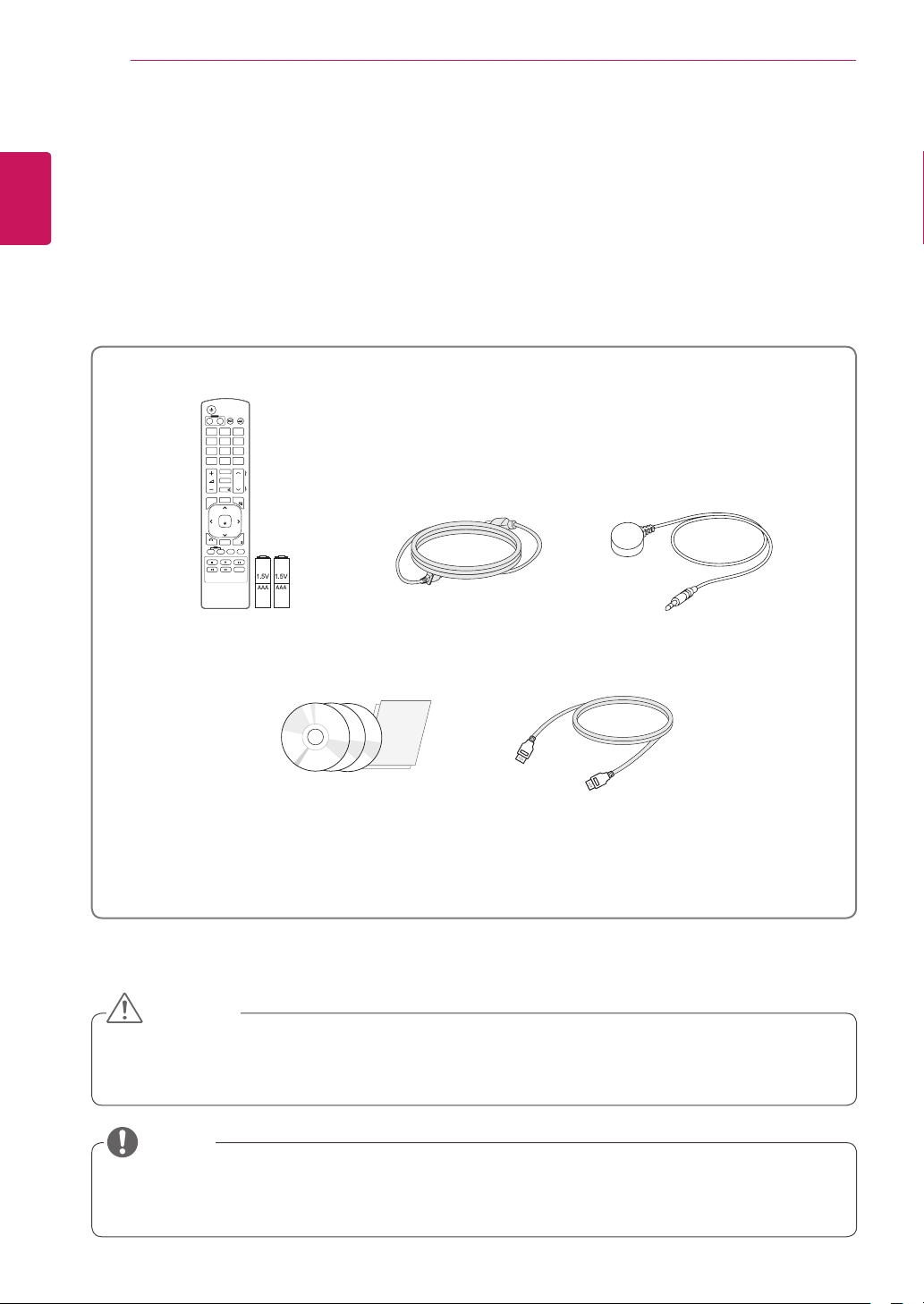
Accessories
Check your product box for the following items. If there are any missing accessories, contact the local
dealer where you purchased your product. The illustrations in this manual may differ from the actual product
and accessories.
POWER
INPUT
ENERGY
MONITOR
OFF
ON
SAVING
. , !ABCDEF
GHIJKLMNO
PQRSTUV
WXYZ
1/a/A
CLEAR
- * #
MARK
ARC
P
A
BRIGHT
PSM
G
NESS
E
MUTE
AUTO
S.MENU
MENU
OK
EXIT
BACK
TILE
ID
OFF
ON
Remote control and Batteries Power Cord
IR Receiver
CD(Owner's Manual,
HDMI Cable
SuperSign Program/Owner's
Manual)/ Card
CAUTION
Do not use any unapproved or counterfeit parts or accessories to ensure the safety and product life
y
span.
Any damages or injuries by using pirated items are not covered by the warranty.
y
NOTE
The accessories supplied with your product may vary depending on the model.
y
Product specifications or contents in this manual may be changed without prior notice due to upgrade
y
of product functions.
Page 5
ASSEMBLING AND PREPARING
5
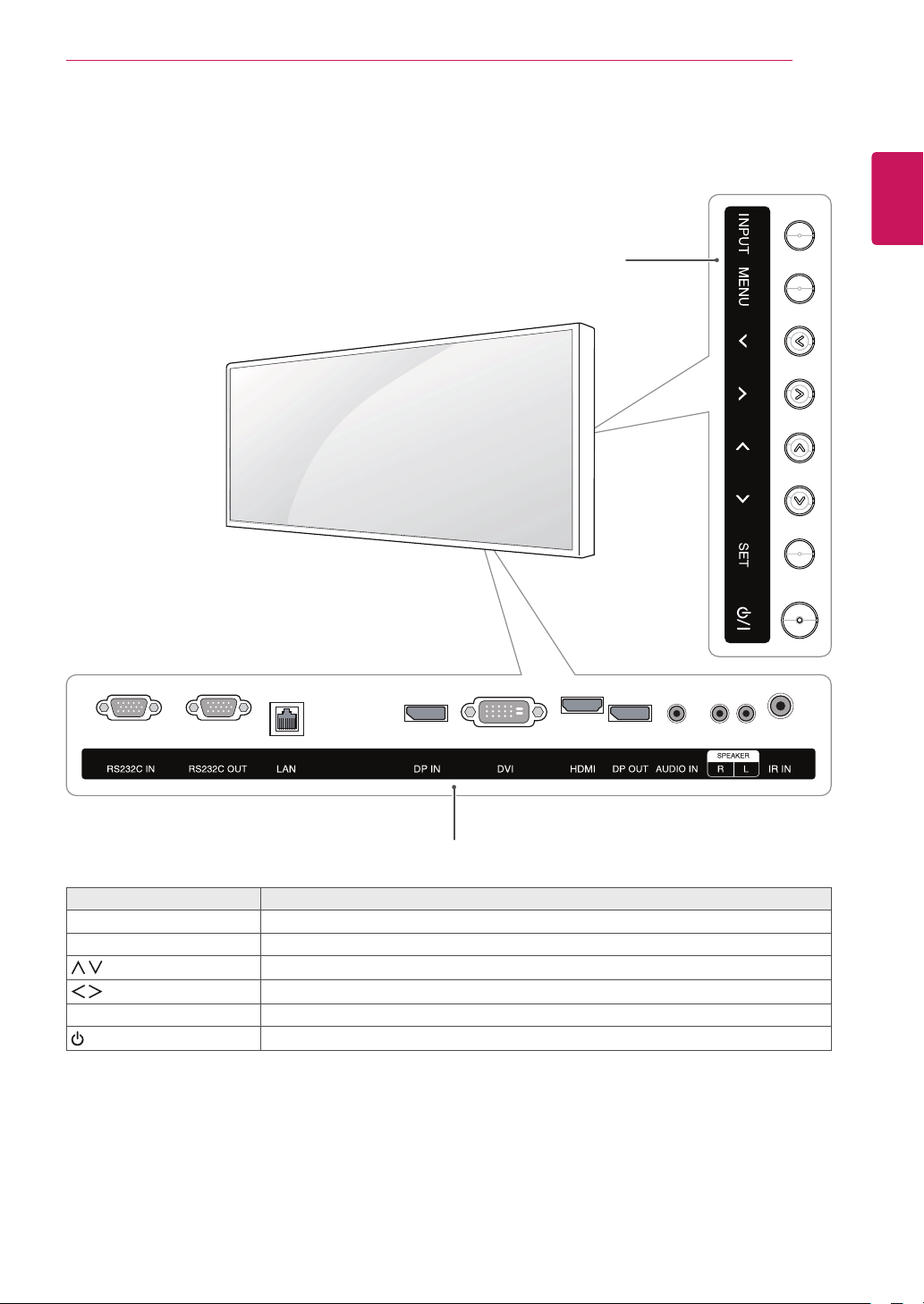
Parts and buttons
ENGLISH
ENG
Screen Buttons/ Screen Marks
Connection panel
Screen Marks Description
INPUT Changes the input source.
MENU Accesses the main menus, or saves your input and exits the menus.
Adjust the up and down.
Adjusts the volume level.
AUTO/SET Displays the current signal and mode.
/ I
Turns the power on or off.
Page 6

ASSEMBLING AND PREPARING
6
ENGLISH
STORAGE METHOD FOR PANEL PROTECTION
ENG
Correct Method Incorrect Method
If the product needs to be set upright, hold both
sides of the product, and tilt backward carefully
for. Do not let the panel not to touch the floor.
Panel
Panel
If the product is tilted onto the bezel, the bottom of
the panel may be damaged.
Panel
When laying down the product, lay a cushion on a
flat floor. Put the product on it with the panel of
the product facing down.
Cushion
Panel
If there is not a cushion available, ensure the floor is
clean and then lay the product down carefully with the
panel facing either upward or downward.
be careful for objects not to fall on the panel.
At this time,
Panel
If the product is tilted onto the edge of the panel,
the panel may be damaged.
Page 7

ASSEMBLING AND PREPARING
7
Using the IR Receiver
This allows a remote control sensor to be placed in a custom location.
IR Receiver cable
ENGLISH
ENG
NOTE
The IR receiver is made with a magnet. You can attach the IR receiver on the side, top, or bottom
y
of the product.
It may fall down if exposed to external shock.
y
Page 8
ASSEMBLING AND PREPARING
8
ENGLISH
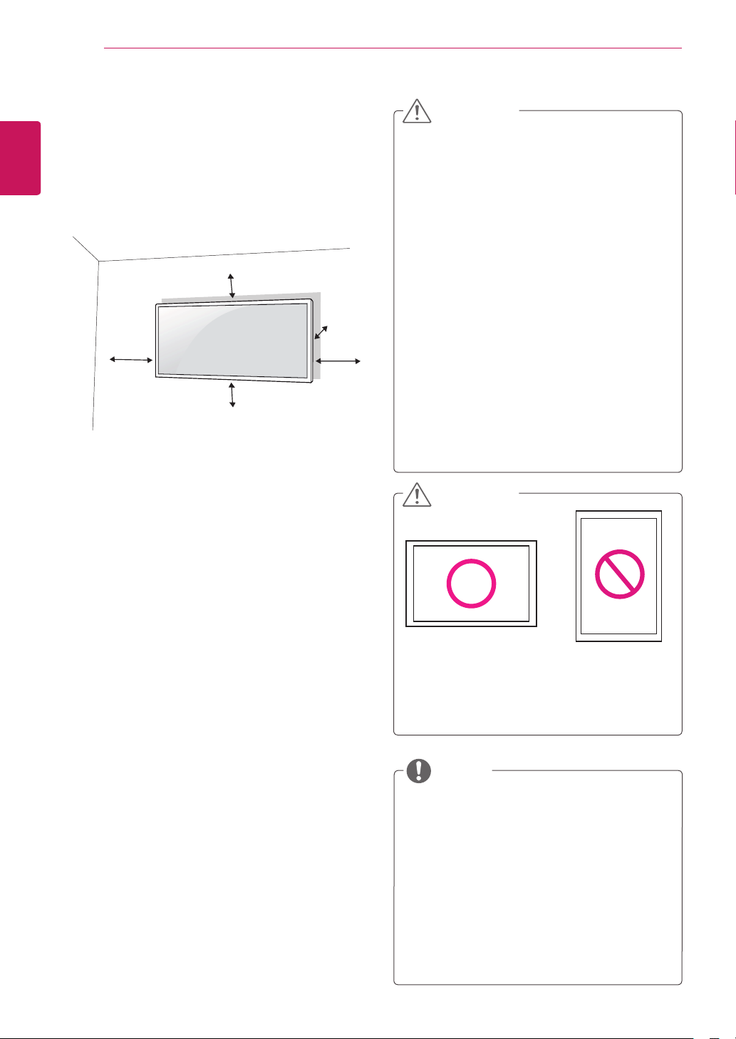
Mounting on a wall
ENG
For proper ventilation, allow a clearance of 10
cm on each side and from the wall. Detailed
installation instructions are available from your
dealer, see the optional Tilt Wall Mounting Bracket
Installation and Setup Guide.
To install the monitor to a wall, attach a wall mounting bracket (optional) to the back of the monitor.
Make sure that the wall mounting bracket is securely
fixed to the monitor and to the wall.
10 cm
10 cm
10 cm
10 cm
10 cm
CAUTION
Unplug the power cord before moving or in-
y
stalling the monitor to avoid electric shocks.
Installing the monitor on the ceiling or on a
y
slanted wall may result in the monitor falling
off, which could lead to injury. Please use
the genuine LG wall mounting bracket. For
more information, contact your local retail
store or a qualified installer.
Applying excessive force when fastening
y
screws may cause damage to the monitor. Damage caused in this way will not be
covered by the product warranty.
Use the wall mounting bracket and screws
y
that conform to the VESA standard. Damage caused by the use or misuse of inappropriate components will not be covered
by the product warranty.
Installing a monitor lengthwise may damage
y
the pixels on the screen.
CAUTION
1 Use the screws and wall mounting bracket that
comply with the VESA standard.
2 Screws which are longer than the standard
length may damage the inside of the monitor.
3 A non-VESA standard screw may damage the
product and cause the monitor to fall. LG Electronics is not liable for any accidents relating to
the use of non-standard screws.
4 The monitor is VESA standard compliant.
5 Use it according to the VESA standard as speci-
fied below.
784.8 mm or less
y
* Fastening screw: Diameter 4.0 mm x Pitch 0.7
mm x Length 10 mm
Installing a monitor lengthwise may damage
y
the pixels on the screen.
NOTE
The wall mount kit includes the installation
y
guide and all necessary parts.
The wall mounting bracket is optional. The
y
accessories can be purchased at your local
retail store.
The length of the screw may differ for each
y
wall mounting bracket. Ensure the correct
length screw is used.
For more information, please refer to the
y
user manual for the wall mounting bracket.
Page 9

REMOTE CONTROL
9
REMOTE CONTROL
The descriptions in this manual are based on the buttons of the remote control. Please read this manual
carefully and use the Monitor correctly.
To replace batteries, open the battery cover, replace batteries (1.5 V AAA) matching and ends to the
label inside the compartment, and close the battery cover.
To remove the batteries, perform the installation actions in reverse.
CAUTION
Do not mix old and new batteries, as this
y
may damage the remote control.
Make sure to point the remote control at the
y
remote control sensor on the Monitor.
ENGLISH
ENG
(POWER)
Turns the Monitor on or off.
MONITOR ON / OFF
Turn off the monitor and then
turn it back on.
1/a/A Button
This button selection is not
applicable.
ARC
Selects the Aspect Ratio Mode.
(It may not work depending on
the model.)
MARK
This button selection is not
applicable.
Volume Up / Down
Adjusts the volume level.
PSM
Selects the Picture Status
Mode.
MUTE
Mutes all sounds.
ENERGY SAVING
Adjusts the brightness of
the screen to reduce energy
consumption.
INPUT
Selects the input mode.
Number and Alphabet buttons
Enters numbers.
The alphabet selection is not
applicable.
CLEAR
This button selection is not
applicable.
BRIGHTNESS Key
Adjust the brightness by
pressing the Up and Down
buttons on the remote control.
Page 10

10
ENGLISH
ENG
REMOTE CONTROL
MENU (See p.19)
Accesses the main menus
or saves your input and exit
menus.
Navigation buttons
Scrolls through menus or
options.
AUTO
This button selection is not
applicable.
OK
Selects menus or options and
confirms your input.
BACK
Allows the user to move back
one step.
ID ON/OFF
This button selection is not
applicable.
S.MENU
(SuperSign Menu Key)
This button selection is not
applicable.
EXIT
Clears all on-screen displays
and returns to Monitor
viewing from any menu.
TILE
Selects the TILE Mode.
(It may not work depending
on the model.)
USB Menu control buttons
This button selection is not
applicable.
Page 11

USING THE MONITOR
11
USING THE MONITOR
Connecting to a PC
Your Monitor supports the Plug & Play* feature.
* Plug & Play: This is the function that allows a PC to use the monitor without installing a driver.
NOTE
It is recommended to use the Monitor with the HDMI connection for the best image quality.
y
Use a shielded signal interface cable, such as DVI/HDMI cable, with a ferrite core to maintain standard
y
compliance for the product.
If you turn the Monitor on when the set becomes cold, the screen may flicker. This is normal.
y
Some red, green, or blue spots may appear on the screen. This is normal.
y
CAUTION
Connect the signal input cable and tighten it by turning the screws clockwise.
y
Do not press the screen with your finger for a long time as this may result in
y
temporary distortion on the screen.
Avoid displaying a fixed image on the screen for a long period of time to
y
prevent image burn. Use a screensaver if possible.
ENGLISH
ENG
Page 12
USING THE MONITOR
12
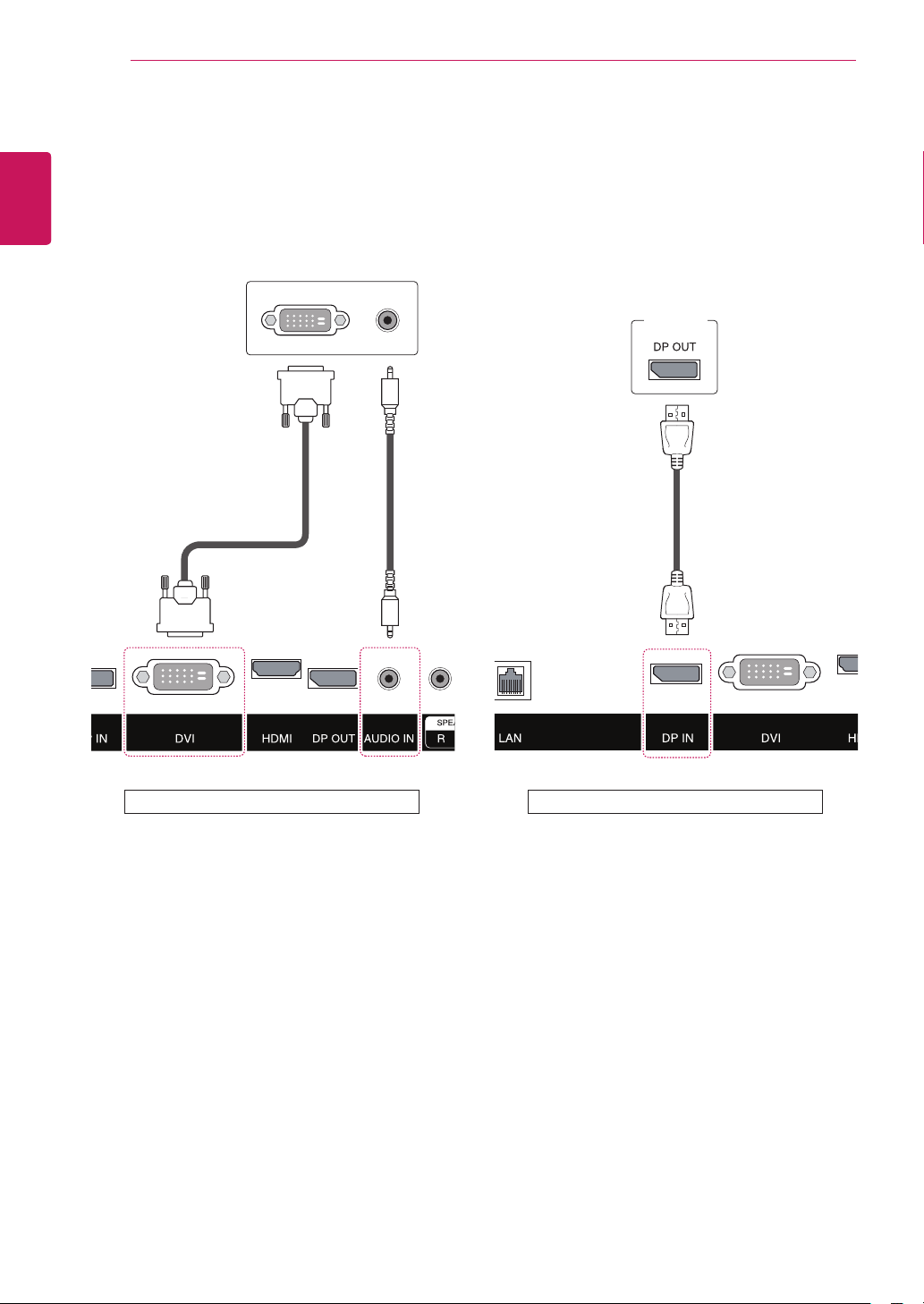
DVI connection
ENGLISH
ENG
Transmits digital video signals to the monitor. Connect the monitor using the DVI cable as illustrated
below. Select the DVI input after connecting. To
transmit an audio signal, connect additional audio
cables.
Display Port connection
Transmits the digital video and audio signals from
your PC to the Monitor. Connect the PC and the
Monitor with the Display Port cable as shown in
the following illustrations.
PC
(not included) (not included)
Back of the Product Back of the Product
Page 13
USING THE MONITOR
13
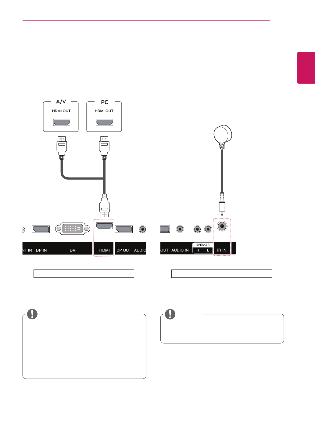
HDMI connection
Transmits the digital video and audio signals from
your PC and A/V devices to the monitor. Connect
your PC and AV device to the monitor with the
HDMI cable as illustrated below.
(not included) (not included)
IR Receiver connection
Allows the use of a wired remote or IR receiver
extension.
ENGLISH
ENG
Back of the Product
NOTE
Use a High Speed HDMI™ cable.
y
High Speed HDMI™ cables transmit an HD
y
signal up to 1080p and higher.
Please check your PC settings if you cannot
y
hear any sound in HDMI mode. Some PCs
require you to manually change the default
audio output to HDMI.
Back of the Product
NOTE
Make sure the power cable is disconnected.
y
Page 14

14
Network
LAN connection
ENGLISH
ENG
A
USING THE MONITOR
Using a router(Switch)
LAN
Monitor
Using the Internet.
B
LAN
Monitor
Switch
PC
PC
Page 15

USING THE MONITOR
15
Daisy Chain Monitors
This function displays digital video signals from your PC on multiple monitors.
Connect a signal input cable (DVI cable) to the DVI IN port of Monitor 1.
1
Connect the other end of the signal input cable to your PC.
2
Connect one end of another signal input cable to the DIV OUT port of Monitor 1 and the other end to the
3
DIV IN of Monitor 2.
DP Cable
Cable
DP
(not included)
Monitor 1 Monitor 2 Monitor 3 Monitor 4
ENGLISH
ENG
NOTE
The number of monitors that can be connected to one output may vary depending on signal
y
strength and signal loss. If you want to connect more than this number of monitors, it is recommended
to use a distributor.
It is also recommended to use lossless cables when linking multiple monitors through the in/out
y
ports.
Use DP version 1.1 (Menu>Settings>DP1.2>Off) when linking multiple monitors through the in/out
y
ports.
Up to 40 monitors can be connected in the DP mode. (When using the Display Port cable provided
y
by LG Electronics.)
Page 16

USING THE MONITOR
16
ENGLISH
ENG
Using additional options
Adjusting aspect ratio
Resize the image to view the image at its optimal size by pressing ARC while you are watching content.
CAUTION
If a fixed image displays on the screen for a long period of time, it will be imprinted and become a
y
permanent disfigurement on the screen. This is “image burn” or “burn-in” and not covered by the
warranty.
To prevent image sticking, do not play a still image for more than two hours.
y
If the aspect ratio is set to Origianl or 1:1 for a long period of time, image burn may occur on the
y
letterboxed area of the screen.
NOTE
You can also change the image size by accessing the main menus.
y
Page 17

ENTERTAINMENT
17
ENTERTAINMENT
Connecting to a wired network
(Depending on model)
Connect the display to a local area network (LAN)
via the LAN port as shown on the following illustration and set up the network settings.
This monitor only supports a wired network connection.
After making a physical connection, a small
number of home networks may require the display
network settings to be adjusted. For most home
networks, the display will connect to automatically
without any adjustments.
For detail information, contact your internet provider or router manual.
ENGLISH
ENG
To set up the network seetings: (Even if your display has already connected automatically, running
setup again will not harm anything),
1 Press MENU to access the main menus.
2 Press the Navigation buttons to scroll to NET-
WORK and press OK.
3 Press the Navigation buttons to select Net-
work Setting and press OK. If Interface Select
is set to RS-232C, change the Interface Select
setting to LAN.
4 Select DHCP or Customer Setting.
- If selecting Customer Setting, press the
Navigation and Number buttons. IP addresses will need to be input manually.
-Press OK and use Up, Down, Number keys to
change the values. Press OK again to finish
changing values.
- DHCP: Select this if there is a DHCP server
(Router) on the local area network (LAN) via
wired connection, the display will automatically be allocated an IP address. If you’re using
a broadband router or broadband modem that
has a DHCP (Dynamic Host Configuration
Protocol) server function. The IP address will
automatically be determined.
Internet
CAUTION
y Do not connect a modular phone cable to the
LAN port.
y Since there are various connection meth-
ods, please follow the specifications of your
telecommunication carrier or internet service
provider.
5 When you are finished, press EXIT.
CAUTION
y Network setting menu will not be available
until the display is connected to physical
network.
y Since there are various connection meth-
ods, please follow the specifications of your
telecommunication carrier or internet service
provider.
Page 18

ENTERTAINMENT
18
ENGLISH
NOTE
y If you want to access the Internet directly on
your display, the internet connection should
always be on.
y If you cannot access the Internet, check
the network conditions from a PC on your
network.
y When you use Network Setting, check the
LAN cable or check if DHCP in the router is
turned on.
y If you do not complete the network settings,
the network may not work properly.
Tips for Network setting
y Use a standard LAN cable with this display. Cat5
or better with a RJ45 connector.
y Many network connection problems during set
up can often be fixed by re-setting the router
or modem. After connecting the display to the
home network, quickly power off and/or disconnect the power cable of the home network router
or cable modem. Then power on and/or connect
the power cable again.
y Depending on the internet service provider
(ISP), the number of devices that can receive
internet service may be limited by the applicable
terms of service. For details, contact your ISP.
y LG is not responsible for any malfunction of the
display and/or the internet connection feature
due to communication errors/malfunctions associated with your internet connection, or other
connected equipment.
y LG is not responsible for problems within your
internet connection.
y You may experience undesired results if the
network connection speed does not meet the
requirements of the content being accessed.
y Some internet connection operations may not
be possible due to certain restrictions set by the
Internet service provider (ISP) supplying your
Internet connection.
y Any fees charged by an ISP including, without
limitation, connection charges are your responsibility.
y A 10 Base-T or 100 Base-TX LAN port is
required when using a wired connection to this
display. If your internet service does not allow for
such a connection, you will not be able to connect the display.
y A DSL modem is required to use DSL service
and a cable modem is required to use cable
modem service. Depending on the access
method of and subscriber agreement with your
ISP, you may not be able to use the internet
connection feature contained in this display or
you may be limited to the number of devices you
can connect at the same time. (If your ISP limits
sub-scription to one device, this display may
not be allowed to connect when a PC is already
connected.)
y The use of a “Router” may not be allowed or its
usage may be limited depending on the policies
and restrictions of your ISP. For details, contact
your ISP directly.
Page 19

CUSTOMIZING SETTINGS
19
CUSTOMIZING SETTINGS
Menu Settings
To view the Menu OSD, press the Menu button at the bottom of the monitor.
1
Use the < or > buttons to set the options.
2
Select button to exit the OSD menu.
3
100 70 30 DVI Wide
Brightness
Contrast Volume Input Ratio Func. PIP
전전
Picture Color Settings
Time Network
ENGLISH
ENG
Reset Exit
Each option is described below.
Menu Description
Brightness
Contrast
Volume Adjusts the volume.
Adjusts the brightness and contrast of the screen.
NOTE
Selecting the Menu button in the Volume menu will enable/disable the
y
Mute function.
Input Selects the current input mode.
Ratio Adjusts the screen ratio.
Func.
PIP Displays the screens of two input modes on one monitor.
Picture Adjusts the sharpness, black level,, and response time of the screen.
Color Adjusts the gamma, color temperature, and color balance of the screen.
Settings Sets the Language, PC/AV mode, Main Audio,TileMode, ISM Method, Key Lock, Set ID, DPM
Time Sets the On/Off timer, Auto off, 4 Hours Off, and Sleep Timer.
Network Sets the RS-232C and LAN.
Reset Resets to the default settings as of the day of purchase. Press the <, > buttons to reset immedi-
Exit Exits the OSD menu.
Adjusts ECO, and picture mode.
Select, Information, and OSD Lock. (Tile mode may not work depending on the model.)
ately.
Page 20

20
Ratio Settings
ENGLISH
ENG
1
2
3
4
5
Sub Menu
Each option is described below.
CUSTOMIZING SETTINGS
To view the Menu OSD, press the Menu ( ) button at the bottom of the monitor.
Press < or > to go to Ratio.
Press OK to select Ratio.
Use the < or > buttons to set the options.
Select to exit the OSD menu.
Wide Original 1:1Cinema1 Cinema2 Back Exit
Ratio
Menu > Ratio Description
Wide Displays the video in wide-screen, regardless of the video signal input.
Cinema1 Enlarges the screen with an aspect ratio of 21:9. (at 1080p)
Cinema2 Enlarges the screen with an aspect ratio of 21:9 including the black box area at the bottom for
Original Displays a video according to the input video signal aspect ratio.
1:1
Back
Exit
subtitles. (at 1080p)
The aspect ratio is not adjusted from the original.
Moves to the previous OSD screen.
Exits the OSD menu.
NOTE
The display may look the same for Wide, Original and 1:1 options at the recommended resolution
y
(2560 x 1080).
The ratio is disabled in the interlaced signal.
y
Page 21

CUSTOMIZING SETTINGS
Func. Settings
To view the Menu OSD, press the Menu ( ) button at the bottom of the monitor.
1
Press < or > to go to Func.
2
Press OK to select Func.
3
Use the < or > buttons to set the options.
4
Select to exit the OSD menu.
5
Sub Menu
21
ENGLISH
ENG
Func.
Off Off
ECO Picture
Func.
Reset Back Exit
Mode
Each option is described below.
Menu > Func. Description
ECO On Enables the ECO function, which allows you to save energy according to the ECO
Off Disables the ECO function.
Reset Resets the ECO data.
Picture Mode Changes depending on the value of PC/AV Mode in Menu > Settings.
PC Mode
Custom Allows the user to adjust each element. The color mode of the main menu can be ad-
Text Optimizes the screen for document processing.
Photo Optimizes the screen to view photos.
Cinema Optimizes the screen to improve the visual effects of a video.
Game Optimizes the screen for gameplay.
AV Mode
Custom Allows the user to adjust each element. The color mode of the main menu can be
Standard Optimizes the screen to display normal picture quality.
VIVID 1 Optimizes the screen for vivid visual effects.
VIVID 2 Optimizes the screen for more vivid visual effects.
Cinema Optimizes the screen to improve the visual effects of a video.
Reset Func. Resets the monitor to its original factory settings.
Back Moves to the previous OSD screen.
Exit Exits the OSD menu.
efficiency level.
justed.
adjusted.
Page 22

22
PIP settings
ENGLISH
ENG
1
2
3
4
5
Sub Menu
CUSTOMIZING SETTINGS
To view the Menu OSD, press the Menu ( ) button at the bottom of the monitor.
Press < or > to go to PIP.
Press OK to select PIP.
Use the < or > buttons to set the options.
Select to exit the OSD menu.
PIP
BalancedOff Bottom R
PIP Size Position
PIP
Reset Back Exit
Each option is described below.
Menu > PIP Description
PIP Displays the screens of two input modes on one monitor.
Size Adjusts the size of the secondary screen.
Position Adjusts the position of the secondary screen.
Reset Resets the PIP function to the default settings.
Back Moves to the previous OSD screen.
Exit Exits the OSD menu.
(DVI+DP, HDMI1+DP, HDMI2+DP, DP+DVI, DP+HDMI1, DP+HDMI2)
Balanced Uses a balanced size for the secondary screen.
Small
Medium Shows the secondary screen in a normal size display.
Large
16:9VS5:9
5:9VS16:9
The default value is Bottom Right.
Bottom
Right
Bottom Left Shows the secondary screen in the bottom left of the display.
Top Left Shows the secondary screen in the top left of the display.
Top Right Shows the secondary screen in the top right of the display.
Shows the secondary screen in a small size display.
Shows the secondary screen in a large size display.
Shows 16:9 widescreen on the Main screen.
Shows 5:9 widescreen on the Subscreen.
Shows 5:9 widescreen on the Main screen.
Shows 16:9 widescreen on the Subscreen.
Shows the secondary screen in the bottom right of the display.
NOTE
If the PIP mode is off, Position is disabled.
y
If Size is set to Balance, Position is disabled.
y
Page 23

PIP/PBP
Displays videos or photos stored in the USB device
on a single monitor by dividing it into the main and
sub screens.
Mode
*PIP(Picture In Picture): Displays the Sub screen
in the main screen.
*PBP (Picture by Picture): Splits the display into
the main screen and a sub screen.
CUSTOMIZING SETTINGS
23
ENGLISH
ENG
Main
screen
PIP
Sub
screen
PBP
Position
Adjusts the position of the subscreen (top left,
bottom left, top right, bottom right)
top left top right
bottom left bottom right
Size
Adjusts the size of the subscreen.
10 : 960x540
PIP
0 :
480x270
Page 24

CUSTOMIZING SETTINGS
24
ENGLISH
Picture
ENG
1
2
3
4
5
Sub Menu
Sharpness Black Level Response
Each option is described below.
To view the Menu OSD, press the Menu button at the bottom of the monitor.
Press < or > to go to Picture.
Press OK to select Picture.
Use the < or > buttons to set the options.
Select to exit the OSD menu.
Low5 Middle
Time
Menu > Picture Description
Sharpness Adjusts the sharpness of the screen.
Black Level Sets the offset level (for HDMI only).
Offset: as a reference for a video signal, this is the darkest color the monitor can display.
High
Low The picture of the screen gets darker.
Response Time Sets a response time for displayed pictures based on the speed of the screen. For a normal en-
vironment, it is recommended that you use Normal. For a fast-moving picture, it is recommended
that you use High.
Setting to High may cause image sticking.
High Sets the response time to High.
Middle Sets the response time to Middle.
Low Sets the response time to Low.
Reset Resets the Picture function to the default settings.
Back Moves to the previous OSD screen.
Exit Exits the OSD menu.
Picture
Reset Back Exit
The picture of the screen gets brighter.
Picture
Page 25

CUSTOMIZING SETTINGS
25
Color
To view the Menu OSD, press the Menu button at the bottom of the monitor.
1
Press < or >to go to Color.
2
Press OK to select Color.
3
Use the < or > buttons to set the options.
4
Select to exit the OSD menu.
5
To return to the upper menu or set other menu items, use the Menu button.
Sub Menu
CustomGamma 1 50 50 50
Gamma
Color Temp
Red Green Blue
Six Color
Each option is described below.
Menu > Color Description
Gamma Custom gamma setting: When using the gamma 0, gamma 1, and gamma 2 monitor settings,
Color Temp Custom
Six Color Meets the user requirements for colors through adjusting the color and saturation of the six colors
Reset Returns the color settings to the default settings.
Back Moves to the previous OSD screen.
Exit Exits the OSD menu.
higher gamma settings mean a brighter image is displayed and vice versa.
Red
Green
Blue
Selects the factory default picture color.
Warm: Sets the screen color to a reddish tone.
Medium: Sets the screen color between a red and blue tone.
Cool: Sets the screen color to a bluish tone.
(red, green, blue, cyan, magenta, yellow) and saving the settings.
Hue Adjusts tone of the screen.
Saturation
You can customize the picture color using Red, Green, and Blue colors.
Adjusts the saturation of the screen colors. The lower the value, less saturated and
bright the colors become. The higher the value, the more saturated and dark the colors
become.
Color
Reset Back Exit
Color
ENGLISH
ENG
Page 26

CUSTOMIZING SETTINGS
26
ENGLISH
Settings
ENG
1
2
3
4
5
Sub Menu
Language
Each option is described below.
To view the Menu OSD, press the Menu button at the bottom of the monitor.
Press < or > to go to Settings.
Press OK to select Settings.
Use the < or > buttons to set the options.
Select to exit the OSD menu.
AV
PC/AV
Mode
Audio-In
Main Audio
Tile
Mode
Off
ISM Method
On
DPM Select
Off
Key Lock
Set ID
Off
OSD Lock
Informa-
Settings
Settings
Reset
Back Exit
tion
Menu > Settings Description
Language Sets the menu screen to the desired language.
PC/AV Mode Enabled in HDMI mode only.
Main Audio The sound coming through the Audio In port of the digital input signal (HDMI, HDMI2/MHL, Display
Tile Mode Sets the Tile Mode, Tile ID, and Natural Mode. (It may not work depending on the model.)
ISM Method Sets the functionality of preventing afterimage on the screen.
Key Lock Turns the local key function on or off. If this function is enabled, the local key does not work.
DPM Select A user can choose to turn the power saving mode on / off.
Set ID You can assign a unique Set ID NO (name assignment) to each product when several products
OSD Lock Prevents incorrect key input.
Port) can be heard through the monitor's speakers. Audio port is converted into the main audio
port when the input is changed.
are connected for display. Specify the number (1 to 255) using the button and exit. Use the
assigned Set ID to individually control each product using the Product Control Program.
On Key input is disabled.
Off Key input is enabled.
NOTE
All functions except for the OSD Lock mode and the Exit button for Brightness, Contrast,
Volume, Input, and Settings are disabled.
Information See the serial number, S/W version, IP address, and MAC address.
Reset Resets the settings to default.
Back Moves to the previous OSD screen.
Exit Exits the OSD menu.
Page 27

Tile Mode
This monitor can be tiled with additional monitors to create a large tiled display.
CUSTOMIZING SETTINGS
27
ENGLISH
ENG
Off
When the Tile Mode
option is disabled
1X2
When using 2 monitors
Tile
ID 1
ID 2
2X2
When using 4 monitors
ID 1
ID 3
ID 2
ID 4
Tile Mode - Natural mode
When active, the part of the image that would normally be displayed in the gap between the monitors is
omitted.
Before After
Page 28

CUSTOMIZING SETTINGS
28
ENGLISH
Time
ENG
1
2
3
4
5
Sub Menu
Each option is described below.
To view the Menu OSD, press the Menu button at the bottom of the monitor.
Press < or > to go to Settings.
Press OK to select Settings.
Use the < or > buttons to set the options.
Select to exit the OSD menu.
Off
Clock Off timerOn Timer Auto off
Setting Description
Clock Sets the time feature.
Off/On Time Sets the time to turn on or off the Monitor.
Auto off If Auto off is active and there is no input signal, the set switches to off mode automatically after 15
minutes.
4 Hours Off If you do not use the monitor for more than 4 hours, it will be in off mode automatically.
Sleep Timer Sets the length of time until the Monitor to turns off. When you turn the Monitor off and turn
it on again, the Sleep Timer will be set to off.
Off Off
4 Hours Off
Off
Sleep Timer
Reset
Time
Back
Exit
NOTE
Off/On Time can be saved for up to seven schedules; the Monitor is turned on or off at the preset time in the
y
schedule list. If multiple preset times are stored in the schedule list, this function works at the nearest time from the
current time.
The scheduled power-off function works properly only when the device time is set correctly.
y
When the scheduled power-on and power-off times are the same, the power-off time has priority over the power-
y
on time if the set is turned on, and vice versa if the set is turned off.
"The ""Automatic Standby"" and ""Auto off"" functions may not be available in some countries."
y
Page 29

CUSTOMIZING SETTINGS
29
Network
To view the Menu OSD, press the Menu button at the bottom of the monitor.
1
Press < or > to go to Settings.
2
Press OK to select Settings.
3
Use the < or > buttons to set the options.
4
Select to exit the OSD menu.
5
Sub Menu
Interface
Select
Each option is described below.
Menu > Settings Description
Interface Select Sets communication with Media Player and the connected PC.
Network Setting Configure the network settings.
Back Moves to the previous OSD screen.
Exit Exits the OSD menu.
Network
Setting
RS-232C Communicates with the connected PC in serial mode.
LAN Communicates with Media Player.
Back Exit
ENGLISH
ENG
Network
Page 30

TROUBLESHOOTING
30
ENGLISH
TROUBLESHOOTING
ENG
No image is displayed
Problem Resolution
Is the product power cord
connected?
Does the 'Out of range'
message appear?
Does the 'Check signal cable'
message appear?
'Unknown Product' message appears when the product is connected.
Problem Resolution
Did you install the driver? y Install the product driver, which is provided with the product, or
y See if the power cord is properly connected to the outlet.
y The signal from the PC (video card) is out of the vertical or horizontal
frequency range of the product. Adjust the frequency range by
referring to the Specifications in this manual.
* Maximum resolution
HDMI/DVI: 2560 x 1080(60Hz)
y The signal cable between PC and product is not connected. Check
the signal cable.
y Press the 'INPUT' menu in the remote Control to check the input
signal.
download it from the web site. (http://www.lg.com)
y See if the plug&play function is supported by referring to the video
card user manual.
'Key Lock On' message appears.
Problem Resolution
The 'Key Lock On' message
appears when pressing the
Menu button.
The screen image looks abnormal.
Problem Resolution
Is the screen position wrong? ySee if the video card resolution and frequency are supported by the
The screen is displayed
abnormally.
After-image appears on the product.
Problem Resolution
After-image appears when the
product is turned off.
The Lock function prevents the OSD settings from being changed
inadvertently. To release the lock, go to Menu and Option and disable
the Key Lock option.
product. If the frequency is out of range, set to the recommended
resolution in the Control Panel "Display" Setting menu.
y The proper input signal is not connected to the signal port. Connect
the signal cable that matches with the source input signal.
yIf you use a fixed image for a long time, the pixels may be damaged
quickly. Use the screen-saver function.
Page 31

The audio function does not work.
Problem Resolution
No sound? ySee if the audio cable is connected properly.
yAdjust the volume.
y See if the sound is set properly.
Sound is too low. y Adjust the volume.
Screen color is abnormal.
Problem Resolution
Screen has poor color resolution
(16 colors).
Screen color is unstable or
mono-colored.
Do black spots appear on the
screen?
y Set the number of colors to more than 24 bits (true color) Select
Control Panel - Display - Settings - Color Table menu in Windows.
yCheck the connection status of the signal cable. Or, re-insert the PC
video card.
y Several pixels (red, green, white or black color) may appear on the
screen, which can be attributable to the unique characteristics of the
LCD panel. It is not a malfunction of the LCD.
TROUBLESHOOTING
31
ENGLISH
ENG
The operation does not work normally.
Problem Resolution
The power suddenly turned off. yIs the sleep timer set?
y Check the power control settings. Power interrupted
Page 32

SPECIFICATIONS
32
ENGLISH
SPECIFICATIONS
ENG
LCD Panel Screen Type 1064.67 mm Wide (29 inch) TFT (Thin Film Transistor)
LCD (Liquid Crystal Display) Panel.
Visible diagonal size : 1064.67 mm
Pixel Pitch 0.4833 mm (H) x 0.4833 mm (V)
Video Signa Max. Resolution 2560 x 1080 @ 60 Hz
- It may not be supported depending on the OS or video card type.
Recommended Resolution 2560 x 1080 @ 60 Hz
- It may not be supported depending on the OS or video card type.
Horizontal Frequency 30 kHz to 90 kHz
Vertical Frequency 56 Hz to 75 Hz
Synchronization Type Separate Sync, Composite Sync, Digital
Input Connector HDMI(Digital), RS-232C, LAN, DVI, DP, Audio, Speaker,
IR Receiver
Power Rated Voltage AC 100-240 V~ 50/60 Hz 0.6 A
Power Consumption On Mode : 53 W Typ.
Sleep Mode : ≤ 1.2 W
Off Mode : ≤ 0.5 W
Environmental
conditions
Dimensions
(Width x Height x
Depth) / Weight
Operating Temperature
Operating Humidity
Storage Temperature
Storage Humidity
10 °C to 35 °C
10 % to 80 %
-20 °C to 60 °C
5 % to 90 %
H
W
697.2 mm x 313.2 mm x 50.9 mm / 7.2 kg
* Applicable only for models that support the speakers
Audio RMS Audio Output 10 W + 10 W (R + L)
Input Sensitivity 0.7 Vrms
Speaker Impedance 8 Ω
Product specifications shown above may be changed without prior notice due to upgrade of product
functions.
D
Page 33

Dimensions
The illustrations in this manual may differ from the actual product and accessories.
Please see the "Mounting on a wall" section for sizes of screws. (See p.8)
697.2 48.95
SPECIFICATIONS
313.2
33
ENGLISH
ENG
(Unit : mm)
248.4 200
M4 X L10 (wall mounting screw)/
Product specifications shown above may be changed without prior notice due to upgrade of product
functions.
29
Depth 11mm (maximum)
200
50.9
Page 34

SPECIFICATIONS
34
ENGLISH
ENG
DVI/Display Port/HDMI(PC) supported mode.
Resolution
720 x 400
640 x 480
640 x 480
800 x 600
800 x 600
1024 x 768
1024 x 768
1152 x 864
1280 x 720
1280 x 1024
1280 x 1024
1680 x 1050
1920 x 1080
2560 x 1080
Horizontal
Frequency(kHz)
31.468 70.08
31.469 59.94
37.5 75
37.879 60.317
46.875 75.0
48.363 60.0
60.123 75.029
67.5 75
45 60
63.981 60.02
79.976 75.025
65.29 59.954
67.5 60
66.7 60
Vertical
Frequency(Hz)
AV Mode
Resolution HDMI
480i x
576i x
480p o
576p o
720p o
1080i o
1080p o
NOTE
PC resolutions available for the Input Label
y
option in HDMI/DVI input modes: 640 x
480/60 Hz, 1280 x 720/60 Hz, 1920 x
1080/60 Hz; 480p, 720p and 1080p DTV
resolutions.
NOTE
Vertical frequency: To enable the user to
y
watch the product display, screen image
should be changed tens of times every
second like a fluorescent lamp. The vertical
frequency or refresh rate is the times of
image display per second. The unit is Hz.
Horizontal frequency: The horizontal interval
y
is the time to display one vertical line. When
1 is divided by the horizontal interval, the
number of horizontal lines displayed every
second can be tabulated as the horizontal
frequency. The unit is kHz.
Page 35

CONTROLLING THE MULTIPLE PRODUCT
35
CONTROLLING THE MULTIPLE PRODUCT
Use this method to connect several products to a single PC. You can control several products at a
y
time by connecting them to a single PC.
In the Option menu, Set ID must be between 1 and 99 without being duplicated.
y
Connecting the cable
Connect the RS-232C cable as shown in the picture.
The RS-232C protocol is used for communication between the PC and product. You can turn the
y
product on/off, select an input source or adjust the OSD menu from your PC.
RS-232C Cable
(not included)
PC
Monitor 1 Monitor 2 Monitor 3 Monitor 4
ENGLISH
ENG
RS-232C Configurations
7-Wire Configurations (Standard RS-232C cable)
PC Set
D-Sub 9 D-Sub 9
(Female) (Female)
Communication Parameter
Baud Rate : 9600 BPS
y
Data Length : 8 bit
y
Parity Bit : None
y
Stop Bit : 1bit
y
Flow Control : None
y
Communication Code : ASCII code
y
Use a crossed (reverse) cable
y
3-Wire Configurations (Not Standard)
PC Set
D-Sub 9 D-Sub 9
(Female) (Female)
Page 36

CONTROLLING THE MULTIPLE PRODUCT
36
ENGLISH
Command Reference List
ENG
Some commands are not supported depending on the model.
y
COMMAND
1 2
01
Power
02
Input Select
03
Ratio
04
Picture Mode
05
Contrast k g 00H to 64H
06
Brightness
07
Sharpness
08
Color Temp
09
MUTE
10
Volume
11
Clock 1 (year/month/day)
12
Clock 2 (hour/minute/second)
13
Off Timer (repeat mode/time)
14
On Timer (repeat mode/time)
15
On Timer Input
16
Sleep Timer
17
Auto Off
18
Language
19
ISM Method
20
DPM Select
21
Reset
22
Tile Mode
23
Tile ID
24 Natural Mode (in Tile Mode) d j
25
OSD Menu
26
Time elapsed
27
Product serial number
28
SW Version
29
Automatic Standby
k a
x b
k c
d x
k h
k k
x u
k e
k f
f a
f x
f e
f d
f u
f f
f g
f i
j p
f j
f k
d d
d i
k L
d L
f Y
f Z
m N
00H to 01H
See '02. Input Select'
See '03. Ratio'
See '04. Picture Mode'
00H to 64H
00H to 0AH
00H to 03H
00H to 01H
00H to 64H
See '11. Clock 1'
See '12. Clock 2'
See '13. Off Timer'
See '14. On Timer'
See '15. On Timer Input'
00H to 08H
00H to 01H
02H to 14H
See '19. ISM Method'
00H to 01H
00H to 03H
See '22. Tile Mode'
See '23. Tile ID'
00H to 01H
00H to 01H
FFH
FFH
FFH
00H to 01H
DATA
(Hexadecimal)
Page 37

CONTROLLING THE MULTIPLE PRODUCT
37
Transmission / Receiving Protocol
Transmission
[Command1][Command2][ ][Set ID][ ][Data][Cr]
* [Command1] : Identifies between the factory setting and the user setting modes.
* [Command2] : Controls monitor sets.
* [Set ID] : Used for selecting a set you want to control. A unique set ID can be assigned to each set ranging
from 1 to 255 (01H to FFH) in Setting on the OSD menu.
Selecting '00H' for set ID allows the simultaneous control of all connected monitor sets.
* [Data] : Transmits command data.
* [Cr] : Carriage Return. Corresponds to '0x0D' in ASCII code.
* [ ] : White Space. Corresponds to '0x20' in ASCII code.
Acknowledgement
[a][ ][Set ID][ ][OK/NG][Data][x]
* When the product receives data normally, it sends an acknowledgement (ACK) in the format above. At this
time, if the data is Data Read Mode, it indicates present status data to read. If the data is Data Write Mode,
it returns the data sent from your computer.
* Note: Acknowledgement may not be received or receiving may be delayed until monitor booting is
complete.
* If a command is sent with Set ID '00' (=0x00), the data is reflected to all monitor sets and they do not send
any acknowledgement (ACK).
ENGLISH
ENG
Page 38

CONTROLLING THE MULTIPLE PRODUCT
38
01. Power (Command: k a)
ENGLISH
ENG
02. Input Select (Command: x b)
* Controls switching the set on/off.
Transmission
[k][a][ ][Set ID][ ][Data][Cr]
Data 00: Power off
01: Power on
Acknowledgement
[a][ ][Set ID][ ][OK/NG][Data][x]
* Shows the status of power on/off.
Transmission
[k][a][ ][Set ID][ ][FF][Cr]
Acknowledgement
[a][ ][Set ID][ ][OK][Data][x]
Data 00: Power off
01: Power on
* Selects an input signal.
Transmission
[x][b][ ][Set ID][ ][Data][Cr]
Data 70: DVI-D (PC)
90: HDMI (DTV)
A0: HDMI (PC)
D0: Display Port (PC)
Acknowledgement
[b][ ][Set ID][ ][OK/NG][Data][x]
* This feature may not be available depending on
your model.
04. Picture Mode (Command: d x)
* Selects a picture mode.
Transmission
[d][x][ ][Set ID][ ][Data][Cr]
DVI, DP, HDMI input in PC MODE
Data 00: Picture
01: Document
02: Game
05: Custom
06: Cinema
HDMI input in AV MODE
00: Vivid 1
01: Standard
02: Cinema
05: Custom
06: Vivid 2
Acknowledgement
[x][ ][Set ID][ ][OK/NG][Data][x]
05. Contrast (Command: k g)
* Adjusts the screen contrast.
Transmission
[k][g][ ][Set ID][ ][Data][Cr]
Data 00-64: Contrast 0-100
Acknowledgement
[g][ ][Set ID][ ][OK/NG][Data][x]
03. Ratio (Command: k c)
* Adjusts the aspect ratio.
Transmission
[k][c][ ][Set ID][ ][Data][Cr]
Data 02: Wide Screen (16:9)
09: Original
10: Cinema Zoom 1
11: Cinema Zoom 2
0A: 1:1 screen
Acknowledgement
[c][ ][Set ID][ ][OK/NG][Data][x]
06. Brightness (Command: k h)
* Adjusts the screen brightness.
Transmission
[k][h][ ][Set ID][ ][Data][Cr]
Data 00-64: Brightness 0-100
Acknowledgement
[h][ ][Set ID][ ][OK/NG][Data][x]
07. Sharpness (Command: k k)
* Adjusts the screen sharpness.
Transmission
[k][k][ ][Set ID][ ][Data][Cr]
Data 00-0A: Sharpness 0-10
Acknowledgement
[k][ ][Set ID][ ][OK/NG][Data][x]
Page 39

CONTROLLING THE MULTIPLE PRODUCT
39
08. Color Temp (Command: x u)
* Adjusts the screen color temperature.
Transmission
[x][u][ ][Set ID][ ][Data][Cr]
Data 00: Cool
01: Standard
02: Warm
03: Custom
Acknowledgement
[u][ ][Set ID][ ][OK/NG][Data][x]
09. MUTE (Command: k e)
* Mutes/unmutes the volume (sound).
Transmission
[k][e][ ][Set ID][ ][Data][Cr]
Data 00: Mute
01: Unmute
Acknowledgement
[e][ ][Set ID][ ][OK/NG][Data][x]
12. Clock 2 (hour/minute/second) (Command: f x)
* Sets the Clock 2 (hour/minute/second) value.
Transmission
[f][x][ ][Set ID][ ][Data1][ ][Data2][ ][Data3][Cr]
Data1 00-17: 00-23 hours
Data2 00-3B: 00-59 minutes
Data3 00-3B: 00-59 seconds
* Enter "fx [Set ID] ff" to view the Clock 2 settings.
** This function is available only when Clock 1 is set.
Acknowledgement
[x][ ][Set ID][ ][OK/NG][Data1][Data2][Data3][x]
13. Off Timer (repeat mode/time) (Command: f e)
* Sets Off Timer (repeat mode/time).
Transmission
[f][d][ ][Set ID][ ][Data1][ ][Data2][ ][Data3][Cr]
1. f1h to f4h (Read data)
Data1
F1: Reads the 1st Off Timer data
F2: Reads the 2nd Off Timer data
F3: Reads the 3rd Off Timer data
F4: Reads the 4th Off Timer data
Data2 FF
Data3 FF
ENGLISH
ENG
10. Volume (Command: k f)
* Adjusts the volume (sound).
Transmission
[k][f][ ][Set ID][ ][Data][Cr]
Data 00-64: Volume 0-100
Acknowledgement
[f][ ][Set ID][ ][OK/NG][Data][x]
11. Clock 1 (year/month/day) (Command: f a)
* Sets the Clock 1 (year/month/day) value.
Transmission
[f][a][ ][Set ID][ ][Data1][ ][Data2][ ][Data3][Cr]
Data1 0D-63: Year 2013-2099
Data2 01-0C: January-December
Data3 01-1F: 1st-31st
* Enter "fa [Set ID] ff" to view the Clock 1 settings.
Acknowledgement
[a][ ][Set ID][ ][OK/NG][Data1][Data2][Data3][x]
* Checks Off Timer (repeat mode/hour/minute).
Transmission
[f][e][ ][Set ID][ ][Data][ ][f][f][ ][f][f][Cr]
Data f1-f4: First to fourth index number in the Off
Timer list
Acknowledgement
[e][ ][Set ID][ ][OK/NG][Data1][Data2][Data3][Data4]
[x]
Data1 f1-f4: First to fourth index number in the Off
Timer list
Data2 00: Repeat off
02. Daily
03: Mon. - Fri.
04: Mon. - Sat.
05: Sat. - Sun.
06. Every Sunday
07. Every Monday
08. Every Tuesday
09. Every Wednesday
0A. Every Thursday
0B. Every Friday
0C. Every Saturday
Data3 00-17: 00-23 hours
Data4 00-3B: 00-59 minutes
2. e1h-e4h (delete one index), e0h (delete all
indexes)
Data1
E0: Erase all Off Timer settings
E1: Erase the first Off Timer setting
Page 40

CONTROLLING THE MULTIPLE PRODUCT
40
ENGLISH
ENG
14. On Timer (repeat mode/time) (Command: f d)
E2: Erase the second Off Timer setting
E3: Erase the third Off Timer setting
E4: Erase the fourth Off Timer setting
Data2 FF
Data3 FF
* To read or delete the Off Timer list you set, [Data2]
[Data3] must be set to FFH.
3. 02h to 0Ch (Sets weekday for Off Timer)
Data1 00: Repeat off
02. Daily
03: Mon. - Fri.
04: Mon. - Sat.
05: Sat. - Sun.
06. Every Sunday
07. Every Monday
08. Every Tuesday
09. Every Wednesday
0A. Every Thursday
0B. Every Friday
0C. Every Saturday
Data2 00-17: 00-23 hours
Data3 00-3B: 00-59 minutes
** This function is available only when Clock 1 and
Clock 2 are set.
Example 1: fe 01 f1 ff ff – Reads the 1st index data in
Off Timer.
Example 2: fe 01 e1 ff ff – Erases the 1st index data
in Off Timer.
Example3: fe 01 04 02 03 - Sets Off Timer to 02:03
for Monday-Saturday.
* This function is available only when Clock 1 (year/
month/day) and Clock 2 (hour/minute/second) are
set.
Acknowledgement
[e][ ][Set ID][ ][OK/NG][Data1][Data2][Data3][x]
* Sets the On Timer (repeat mode/time).
Transmission
[f][d][ ][Set ID][ ][Data1][ ][Data2][ ][Data3][Cr]
Data1
1. f1h to f4h (Read data)
F1: Reads the first On Timer data
F2: Reads the second On Timer data
F3: Reads the third On Timer data
F4: Reads the fourth On Timer data
Data2 FF
Data3 FF
* Checks On Timer (repeat mode/hour/minute).
Transmission
[f][d][ ][Set ID][ ][Data][ ][f][f][ ][f][f][Cr]
Data f1-f4: First to fourth index number in the On
Timer list
Acknowledgement
[d][ ][Set ID][ ][OK/NG][Data1][Data2][Data3][Data4]
[x]
Data1 f1-f4: First to fourth index number in the On
Timer list
Data2 00: Repeat off
02. Daily
03: Mon. - Fri.
04: Mon. - Sat.
05: Sat. - Sun.
06. Every Sunday
07. Every Monday
08. Every Tuesday
09. Every Wednesday
0A. Every Thursday
0B. Every Friday
0C. Every Saturday
Data3 00-17: 00-23 hours
Data4 00-3B: 00-59 minutes
2. e1h-e4h (delete one index), e0h (delete all
indexes)
Data1
E0: Erase all On Timer settings
E1: Erase the first On Timer setting
E2: Erase the second On Timer setting
E3: Erase the third On Timer setting
E4: Erase the fourth On Timer setting
Data2 FF
Data3 FF
3. 01h to 0Ch (sets weekday for On Timer)
Data1 00: Repeat off
02. Daily
03: Mon. - Fri.
04: Mon. - Sat.
05: Sat. - Sun.
06. Every Sunday
07. Every Monday
08. Every Tuesday
09. Every Wednesday
0A. Every Thursday
0B. Every Friday
0C. Every Saturday
Data2 00-17: 00-23 hours
Data3 00-3B: 00-59 minutes
* To read or delete an On Timer list you have set,
[Data2][Data3] must be set to FFH.
Example 1: fd 01 f1 ff ff - Reads the first index data in
On Timer.
Example 2: fd 01 e1 ff ff - Erases the second index
data in On Timer.
Example 3: fd 01 04 02 03 - Sets On Timer to 02:03
for Monday-Saturday.
* This function is available only when Clock 1 (year/
month/day) and Clock 2 (hour/minute/second) are
set.
* To ensure the On Timer schedule is set correctly,
you must execute the On Timer Input command after
executing this command.
Acknowledgement
[d][ ][Set ID][ ][OK/NG][Data1][Data2][Data3][x]
15. On Timer Input (Command: f u)
Page 41

CONTROLLING THE MULTIPLE PRODUCT
41
* Selects the video input for using On Timer.
Transmission
[f][u][ ][Set ID][ ][Data][Cr]
Data 70: DVI-D (PC)
90: HDMI (DTV)
A0: HDMI (PC)
D0: Display Port (PC)
* This function is only available when Clock 1, Clock
2 and On Timer (repeat mode/time) are set.
* To set the On Timer schedule correctly, the On
Timer (repeat mode/time) command must be
executed prior to this command.
Acknowledgement
[u][ ][Set ID][ ][OK/NG][Data][x]
* Checks the On Timer Input settings.
Transmission
[f][u][ ][Set ID][ ][Data][ ][f][f][Cr]
Data f1-f4: First to fourth index number in the On
Timer Input list
Acknowledgement
[u][ ][Set ID][ ][OK/NG][Data1][Data2][x]
Data1 f1-f4: First to fourth index number in the On
Timer Input list
Data2 70: DVI (PC)
90: HDMI (DTV)
A0: HDMI (PC)
D0: Display Port (PC)
* Sets Auto Off.
Transmission
[f][g][ ][Set ID][ ][Data][Cr]
Data 00: Off (Auto Off disabled)
01: 15 minutes
(The set turns off if there is no signal for 15 minutes.)
Acknowledgement
[g][ ][Set ID][ ][OK/NG][Data][x]
18. Language (Command: f i)
* Sets the language for OSD.
Transmission
[f][i][ ][Set ID][ ][Data][Cr]
Data 02: German
03: English
04: Spanish (Europe)
05: Greek
06: French
07: Italian
0A: Portuguese
0B: Portuguese (Brazil)
0C: Russian
0D: Finnish
0E: Swedish
0F: Korean
10: Chinese
11: Japanese
13: Polish
14: Ukrainian
Acknowledgement
[i][ ][Set ID][ ][OK/NG][Data][x]
ENGLISH
ENG
16. Sleep Timer (Command: f f)
* Sets the sleep timer.
Transmission
[f][f][ ][Set ID][ ][Data][Cr]
Data 00: Off
01: 10 minutes
02: 20 minutes
03: 30 minutes
04: 60 minutes
05: 90 minutes
06: 120 minutes
07: 180 minutes
08: 240 minutes
Acknowledgement
[f][ ][Set ID][ ][OK/NG][Data][x]
17. Auto Off (Command: f g)
19. ISM Method (Command: j p)
* Selects an ISM Method option.
Transmission
[j][p][ ][Set ID][ ][Data][Cr]
Data 02: On
08: Off
Acknowledgement
[p][ ][Set ID][ ][OK/NG][Data][x]
20. DPM Select (Command: f j)
Page 42

CONTROLLING THE MULTIPLE PRODUCT
42
ENGLISH
ENG
21. Reset (Command: f k)
* Sets the DPM mode.
Transmission
[f][j][ ][Set ID][ ][Data][Cr]
Data 00: Off
01: On
Acknowledgement
[j][ ][Set ID][ ][OK/NG][Data][x]
* Returns to the factory settings.
Transmission
[f][k][ ][Set ID][ ][Data][Cr]
Data 02. Factory Reset
Acknowledgement
[k][ ][Set ID][ ][OK/NG][Data][x]
* Sets the Tile ID value of the product.
Transmission
[d][i][ ][Set ID][ ][Data][Cr]
Data 01-a: Tile ID 1-10
FF: Check Tile ID
** The Data value must not exceed the column x row
value.
Acknowledgement
[i][ ][Set ID][ ][OK/NG][Data][x]
24. Natural Mode (in Tile mode) (Command: d j)
* Areas corresponding to the gap between each tile
are removed to give the screen image a more natural
look.
This function is only available when Tile Mode is
enabled.
Transmission
[d][j][ ][Set ID][ ][Data][Cr]
Data 00: Natural Mode off
01: Natural Mode on
Acknowledgement
[j][ ][Set ID][ ][OK/NG][Data][x]
22. Tile Mode (Command: d d)
* Sets the Tile Mode.
Transmission
[d][d][ ][Set ID][ ][Data][Cr]
Data The first byte - Tile column
The second byte - Tile row
Data Description
00 Tile Mode disabled
12 1 x 2 mode (columns x lows)
21 2 X 1 mode
22 2 X 2 mode
31 3 X 1 mode
32 3 X 2 mode
41 4 X 1 mode
42 4 X 2 mode
51 5 X 1 mode
52 5 X 2 mode
Acknowledgement
[d][ ][Set ID][ ][OK/NG][Data][x]
25. OSD Menu (Command: k l)
* Turns the OSD menu on/off.
Transmission
[k][l][ ][Set ID][ ][Data][Cr]
Data 00: OSD off
01: OSD on
Acknowledgement
[l][ ][Set ID][ ][OK/NG][Data][x]
26. Time elapsed (Command: d l)
* Checks the use time of the product.
Transmission
[d][l][ ][Set ID][ ][Data][Cr]
Data FF: Read status
Acknowledgement
[l][ ][Set ID][ ][OK/NG][Data][x]
* The data value received is shown in hexadecimal.
23. Tile ID (Command: d i)
27. Serial No. Check (Command: f y)
Page 43

* Checks the serial number of the product.
Transmission
[f][y][ ][Set ID][ ][Data][Cr]
Data FF: Check product serial number
Acknowledgement
[y][ ][Set ID][ ][OK/NG][Data][x]
* Data is ASCII code.
28. SW Version (Command: f z)
* Checks the software version of the product.
Transmission
[f][z][ ][Set ID][ ][Data][Cr]
Data FF: Check software version
Acknowledgement
[z][ ][Set ID][ ][OK/NG][Data][x]
* The data value received is shown in hexadecimal.
CONTROLLING THE MULTIPLE PRODUCT
43
ENGLISH
ENG
29. Automatic Standby (Command: m n)
Enables the Automatic Standby function (the set
turns off after 4 hours).
Transmission
[m][n][ ][Set ID][ ][Data][Cr]
Data
00: Off
01: On
Acknowledgement
[n][ ][Set ID][ ][OK/NG][Data][x]
Page 44

Make sure to read the Safety Precautions
before using the product.
Keep the Owner's Manual(CD) in an
accessible place for future reference.
The model and serial number of the SET is
located on the back and one side of the SET.
Record it below should you ever need service.
To obtain the source code under GPL, LGPL,
MPL and other open source licenses, that is
contained in this product, please visit http://
opensource.lge.com.
In addition to the source code, all referred
license terms, warranty disclaimers and
copyright notices are available for download.
LG Electronics will also provide open source
code to you on CD-ROM for a charge covering
the cost of performing such distribution (such
as the cost of media, shipping and handling)
upon email request to opensource@lge.com.
This offer is valid for three (3) years from the
date on which you purchased the product.
MODEL
SERIAL
Temporary noise is normal when powering ON or
OFF this device.
 Loading...