

lg 29SA1RL, 29SA1RL-T1, 29SA1RL-Z1 Service Manual
COLOR TV
SERVICE MANUAL
CAUTION
BEFORE SERVICING THE CHASSIS,
READ THE SAFETY PRECAUTIONS IN THIS MANUAL.
CHASSIS : CW62C
MODEL : 29SA1RL
MODEL :
29SA1RL-T1/Z1
North/ Latin America http://aic.lgservice.com
Europe/Africa http://eic.lgservice.com
Asia/Oceania http://biz.lgservice.com
Jun., 2009
Printed in China
P/NO : MFL37794459
Internal Use Only

- 2 -
CONTENTS
Contents...................................................................................................................2
Safety Precautions..............................................................................................3
Specifications........................................................................................................4
Adjustment Instructions .................................................................................5
Trouble Shooting.................................................................................................13
Printed circuit board.........................................................................................17
Block Diagram ......................................................................................................19
Exploded View.....................................................................................................21
SVC. Sheet..................................................................................................................
Copyright©2009 LG Electronics.Inc. All right reserved.
Only for training and service purposes.
LGE Internal Use Only
- 3 -
SAFETY PRECAUTIONS
Many electrical and mechanical parts in this chassis have special safety-related characteristics. These parts are identified by in
the Schematic Diagram and Replacement Parts List.
It is essential that these special safety parts should be replaced with the same components as recommended in this manual to
prevent X-RADIATION, Shock, Fire, or other Hazards.
Do not modify the original design without permission of manufacturer.
General Guidance
An isolation Transformer should always be used during
the servicing of a receiver whose chassis is not isolated from
the AC power line. Use a transformer of adequate power rating
as this protects the technician from accidents resulting in
personal injury from electrical shocks.
It will also protect the receiver and it's components from being
damaged by accidental shorts of the circuitry that may be
inadvertently introduced during the service operation.
If any fuse (or Fusible Resistor) in this TV receiver is blown,
replace it with the specified.
When replacing a high wattage resistor (Oxide Metal Film
Resistor, over 1W), keep the resistor 10mm away from PCB.
Keep wires away from high voltage or high temperature parts.
Due to high vacuum and large surface area of picture tube,
extreme care should be used in handling the Picture Tube.
Do not lift the Picture tube by it's Neck.
X-RAY Radiation
Warning:
To determine the presence of high voltage, use an accurate
high impedance HV meter.
Adjust brightness, color, contrast controls to minimum.
Measure the high voltage.
The meter reading should indicate
23.5 ± 1.5KV: 14-19 inch, 26 ± 1.5KV: 19-21 inch,
29.0 ± 1.5KV: 25-29 inch, 30.0 ± 1.5KV: 32 inch
If the meter indication is out of tolerance, immediate service
and correction is required to prevent the possibility of
premature component failure.
Before returning the receiver to the customer,
always perform an AC leakage current check on the exposed
metallic parts of the cabinet, such as antennas, terminals, etc.,
to be sure the set is safe to operate without damage of
electrical shock.
Leakage Current Cold Check(Antenna Cold Check)
With the instrument AC plug removed from AC source,
connect an electrical jumper across the two AC plug prongs.
Place the AC switch in the on position, connect one lead of
ohm-meter to the AC plug prongs tied together and touch other
ohm-meter lead in turn to each exposed metallic parts such as
antenna terminals, phone jacks, etc.
If the exposed metallic part has a return path to the chassis, the
measured resistance should be between 1MΩ and 5.2MΩ.
When the exposed metal has no return path to the chassis the
reading must be infinite.
An other abnormality exists that must be corrected before the
receiver is returned to the customer.
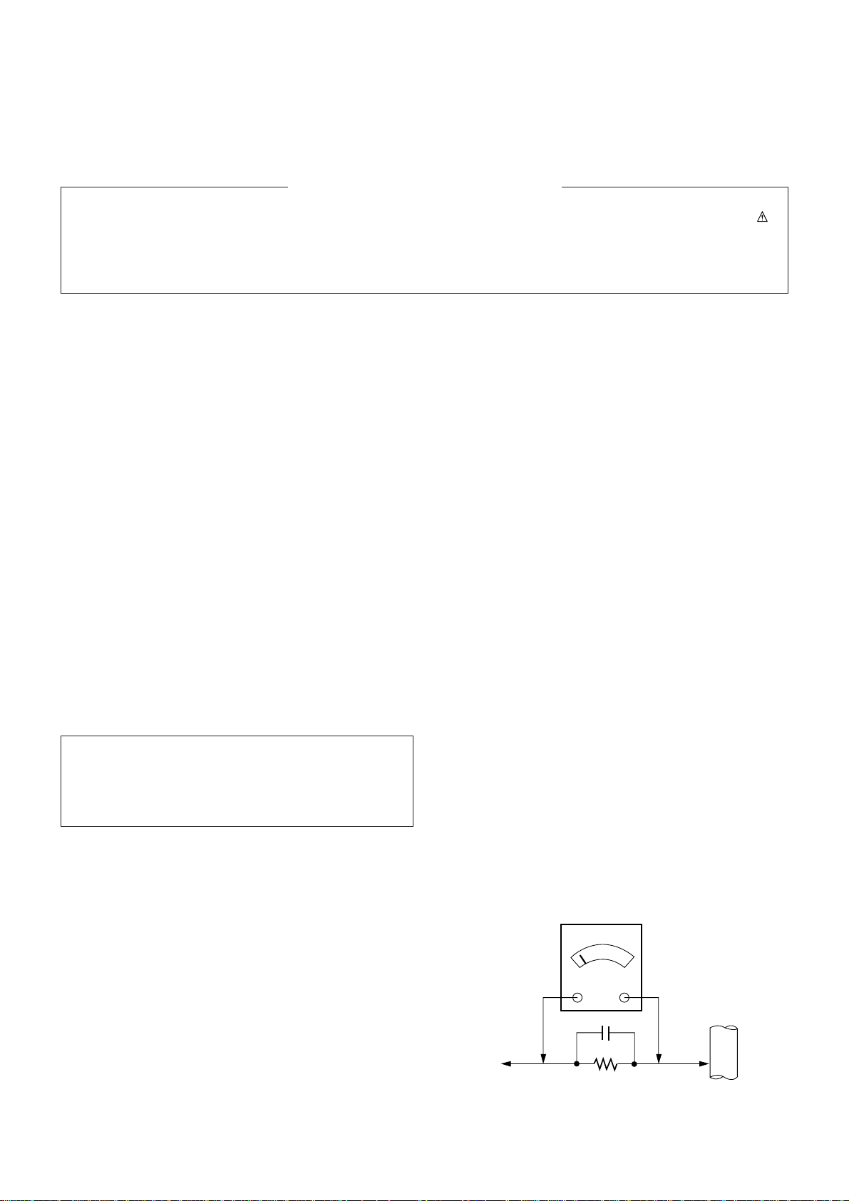
Leakage Current Hot Check (See below Figure)
Plug the AC cord directly into the AC outlet.
Do not use a line Isolation Transformer during this check.
Connect 1.5K/10watt resistor in parallel with a 0.15uF capacitor
between a known good earth ground (Water Pipe, Conduit, etc.)
and the exposed metallic parts.
Measure the AC voltage across the resistor using AC
voltmeter with 1000 ohms/volt or more sensitivity.
Reverse plug the AC cord into the AC outlet and repeat AC
voltage measurements for each exposed metallic part. Any
voltage measured must not exceed 0.75 volt RMS which is
corresponds to 0.5mA.
In case any measurement is out of the limits specified, there is
possibility of shock hazard and the set must be checked and
repaired before it is returned to the customer.
Leakage Current Hot Check circuit
The source of X-RAY RADIATION in this TV receiver is the
High Voltage Section and the Picture Tube.
For continued X-RAY RADIATION protection, the
replacement tube must be the same type tube as specified in
the Replacement Parts List.
IMPORTANT SAFETY NOTICE
0.15uF
Copyright©2009 LG Electronics.Inc. All right reserved.
Only for training and service purposes.
LGE Internal Use Only
To Instrument’s
exposed
METALLIC PARTS
AC Volt-meter
Good Earth Ground
such as WATER PIPE,
CONDUIT etc.
1.5 Kohm/10W
- 4 -
SPECIFICATIONS
Note : Specification and others are subject to change without notice for improvement.
V Scope
This specification can be applied to all the television related to
CW62C Chassis.
V Test and Inspection Method
1) Capability: It follows the TV QC Standard of LGE.
2) Standards of Etc. requirement
- Safety: IEC60065
-EMC : CE standard(EN55020,EN55013)
V Test Condition
Conduct the test as mentioned below.
2.1 Temperature : 25 ± 5°C ( CST 40±5°C)
2.2 Relative Humidity : 65
± 10%
2.3 Power Voltage :
2.4 Follow each drawing or spec for spec and performance of
parts, based upon P/N of B.O.M.
2.5 Warm up TV set for more than 20min. before the
measurement (If no problem in capability,this allow omitted)
No
1
2
3
4
5
6
7
Item
Receiving System
Receiving Channel
Input Voltage
Market
Picture inch
Tuning System
Operating Environment
Storage Environment
Remark
Korea,Japan,Taiwan,North
America,Middle South American
EU /Non EU MODEL
OPTION
Korea,Taiwan,North America.
Middle south American
Japan
1)EU/Non EU Model
2)NTSC-M
(Multi-model NTSC-M)
Korea
Middle south America
North America
Japan
Taiwan
NON-EU
EU
NTSC MODEL
PAL MODEL
200 PR(W/O TXT )
Specification
1) NTSC M
2) NTSC M/ PAL M/N
1) PAL,SECAM BG
2) PAL/SECAM DK
3) PAL-I/I
4) NTSC M
5) NTSC 4.43(AV)
6) SECAM L/L
7) NTSC M/PAL M/N
1) VHF : 02~13
UHF : 14~69
CATV : 02~125
2) VHF/UHF : 1~62CH
CATV : C13~C38CH
TOTAL 88CH
3) VHF : E2 ~ E12
UHF : E21 ~ E69
CATV : S1 ~ S20
HYPER : S21 ~ S41
4) VHF : 02 ~ 13
UHF : 14 ~69
CATV : 02 ~ 71
AC 220V, 60Hz
AC 100 ~ 240V, 50/60Hz
AC 120V, 60Hz
AC 100V, 50/60Hz
AC 110V, 60Hz
AC 110 ~ 240 V/50Hz, 60Hz
AC 230 V 50/60 Hz
Korea, Japan, Taiwan, North
America. Middle South
American ,Filipine, China,
Middle Asia, Asia, EU, CIS
FLAT 29”
FS
FVS 100 program
1)Temp : 0 ~ 45 deg
2)Humidity : under 85 %
1)Temp : -20 ~ 60 deg
2)Humidity : under 85 %
V General Specification
Market Place
Miesast/Africa
EU/CIS
Band
LG
LG
Standard input Voltage
110 ~240 V 50/60Hz
230V 50Hz
Remark
Initial
Copyright©2009 LG Electronics.Inc. All right reserved.
Only for training and service purposes.
LGE Internal Use Only
1. Application Object
This specification can be applied to all the television related to
CW62C Chassis
2. Notes
(1) Because this is a cold chassis, it is not necessary to use
an isolation transformer. However,operating it using a
transformer between the power supply line and chassis
input to prevent electric shock and to protect the test
instrument.
(2)All adjustments must be done in correct sequence.
However, for better productivity, it can be changed in a prepermitted range.
(3) Environment conditions: If not specified, it must be done in
following conditions.
1) Temperature: 25±5°C
2) Humidity : 65±10%
(4) AC Voltage 220V ±10%
(5) If not specified, the receiver must be operated for more
than 20 minutes prior to the adjustment.
(6) Signal: Received the standard color signal. (65dB±1dBuV)
PAL/SECAM: LG standard signal means the digital
pattern PAL_EU 05CH
3. Adjust Item
3.1.1. Preparation for Adjustment.
- Receive PAL-B/G 07ch.(Cross hatch pattern) likes fig.1.
- Select the Picture mode to Standard or clear.
3.1.2. Adjustment.1
Adjust FOCUS VOLUME(the top volume of FBT)
¨and
make the FOCUS of vertical line on the quarter of
screen(red area in fig.1) achieve the best state.
3.2. Purity and Convergence adjustment
Following direction is a case using of None-ITC CPT for CPT
manufacture factory.
This adjustment should be done as below direction.
3.2.1. Purity adjustment
a. Do degauss CPT and Cabinet
b. Receive Red Raster signal. (Gumi PG50ch.)
c. Unfasten fixing Screw of DY, close DY to CPT Funnel DY
as possible as you can.
d. Make R-Land be centered as cross Purity Magnet
That time,4th 6th magnet should keep free gauss status.
e. Make uniform RED Raster as moving DY,
Check there is purity problem or not on R/G/B, white
Raster.Then, Fix screw of DY.
(At this time, be careful about inclination and DY should be
fixed keeping horizontality)
f. Check the TV in direction of EAST, WEST, SOUTH,
NORTH,. Adjust with supporting MAGNET when
adjustment is not operated ..
3.2.2. Adjustment for Convergence
This adjustment should be operated at the best condition of
FOCUS after finishing the PURITY adjustment.
1) BACK RASTER receives black CROSS HATCH signal.
2) Adjust Brightness so that there are 9-12 dots.
3) Widen two tabs of 4pole Magnet with equal angles and
accord red, blue vertical lines at the center of screen.
4) With keeping angle of "c. clause", rotate tab and accord
red/blue, green vertical lines at the center of screen.
- 5 -
ADJUSTMENT INSTRUCTIONS
A
B
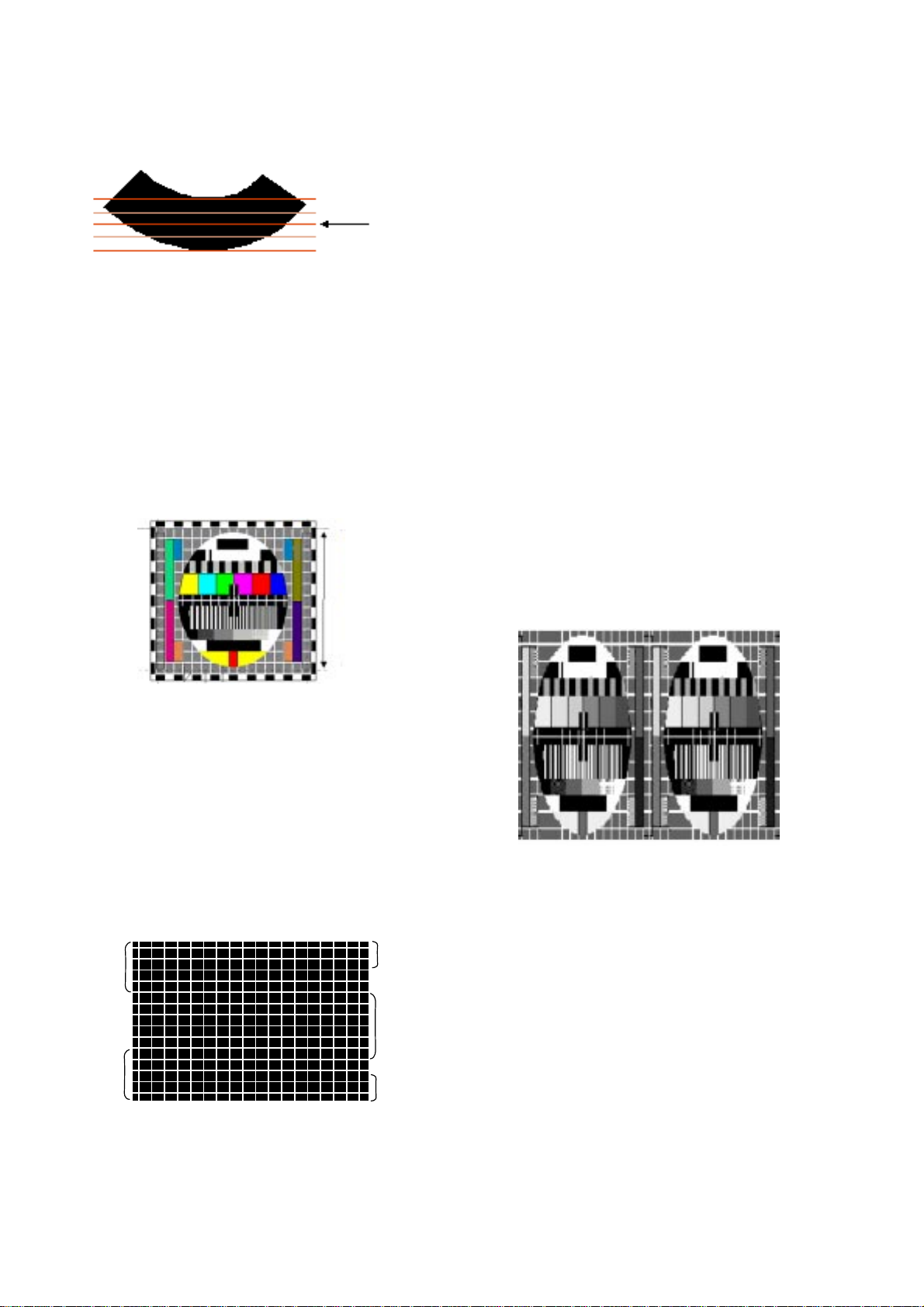
<Fig 1. Cross-Hatch Pattern(NTSC:US 09CH, PAL:E-7 CH)
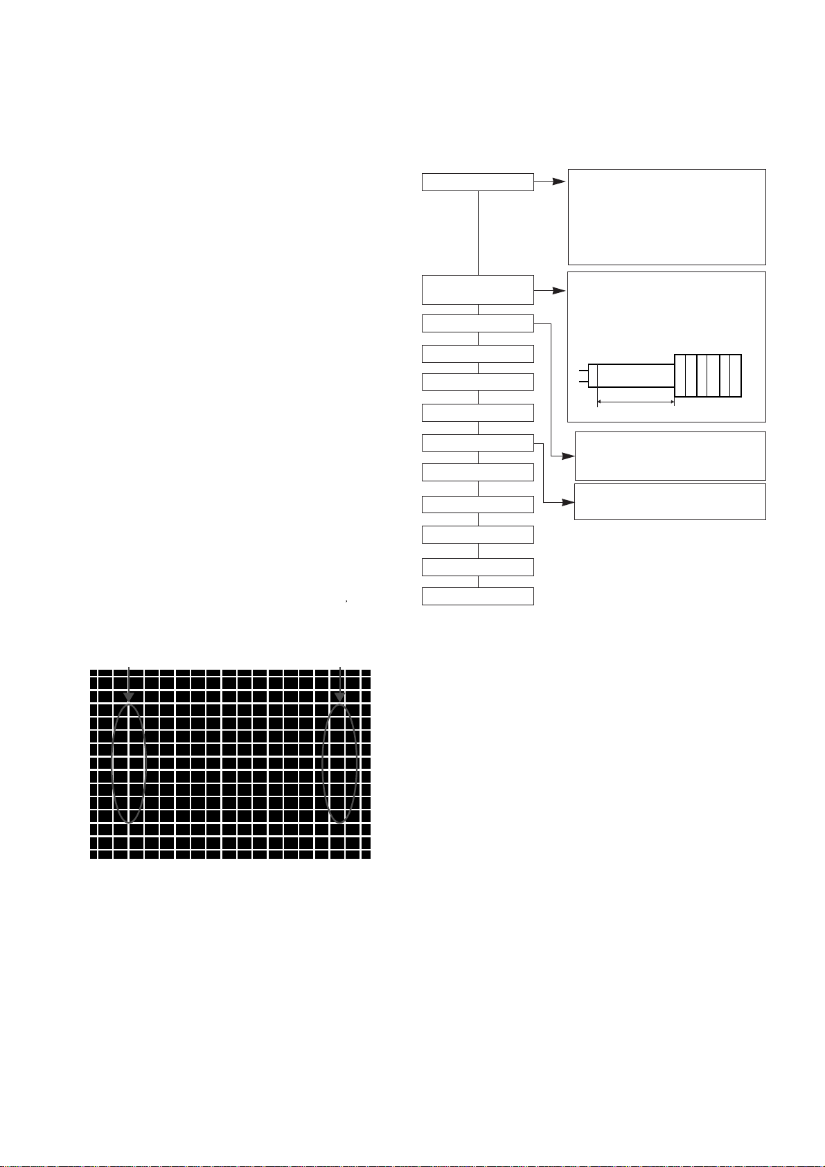
Integrate DY and
Magnet into CPT
CPT Assembly
As preparatory operations before
assembling CPT, wind cotton Tape for
protecting to CPT NECK and DY, CPT
connection parts. At this moment, end
of tape should be over-lapped and
wound in direct route to the NECK.
It needs minimum 15 minutes for
heat run under "standard" picture
condition.
DY FIXED Torque 9~11 kg f.cm
Fix the Magnet to the position as
shown picture below. Be careful not to
make CPT neck shadow while
adjusting DY.
HEAT RUN
Degaussing
STC Pre-Adjustment
Purity adjustment
DY Fixing
SCREEN Voltage adj.
W/B Fix
FOCUS adjustment
STC adujustment
DYC adujustment
Fig.2 Adjustment Sequence
Copyright©2009 LG Electronics.Inc. All right reserved.
Only for training and service purposes.
LGE Internal Use Only
Convergence Magnet
15 ~ 20mm
6Pole
4
2
5) Widen two tabs of 6pole Magnet with equal angles and
accord red, blue vertical lines at the center of screen.
6) With keeping angle of "e. clause", repeat the adjustment
from c to e keeping in mind the movement of red, blue,
green when the horizontal lines are twisted.
7) Move DY up, down, left, right and make the convergence to
be optimal condition and stick rubber
wedge to CPT so that the DY not to move.
3.3 SCREEN & WHITE BALANCE Adjusting
3.3.1. Manual Adjustment Method (use remoncon
for adjusting)
1) Adjust in on RF signal condition or no signal condition.
2) Press ADJ KEY of SVC T/X and select 2.SCREEN ADJ key
for adjustment and generate horizontal line.
Turn the Screen Volume so that horizontal line not to be
shown and then change oppositely to finish the adjustment
at the showing place.
3.3.2. WHITE BALANCE Manual Adjustment.( INSTART ->
SERVICE1)
1) TV set receive 100% White Pattern signal
2) In the state of default setting,adjust BLO-R(R CUT), BLOG(G CUT)
3) In default setting Data
BG(B-DRIVE) is 32,adjust RG(R-
DRIVE), GG(G-DRIVE)
X,Y coordinate satisfy color coordinate below,adjust HIGH
LIGHT(35FL)°
Adjust repeatedly until HIGH LIGHT, LOW LIGHT match.
W/B setting default data refers to W/B TABLE based on
different MODEL.
1. IC
2. White balance IIC Parameter (Address)
3.Color coordinate
3.4 Deflection Setting Data Adjustment
3.4.1. Adjustment Preparation
(1) TV set receive Digital pattern (PAL: E5ch.)
(2) Deflection setting data adjustment can be done only with
remote control.
(3) Press the “INSTART” Key on the factory remote control
continuously to enter Deflection Adjustment mode.
(4) Press the CH
D ,E Key to select adjustment item.
(5) Press the
F ,G Key to change the data.
3.4.2. Adjustment
1.Deflection Setting Data Adjustment,adjust in N50Hz (PAL) mode
firstly,
In USB applied models,PAL Mullti regions,N60Hz(Digtal Pattern)
needs defleetion data adjustment.(07.09.11)
then separately adjust N60Hz(NTSC), Z60Hz, N50Hz, W50Hz,
Z50Hz.(Model with ARC function)
(In N60Hz adjustment, data more than N60Hz can auto transfer
accordingly to N60Hz compensate value, please pay attention to it.)
2. Korea Model adjust only in N60Hz.
3. Middle/south America Model first adjust in N60HZ,then in N50(PAL-N ).
4. After finishing deflection setting data adjustment, press ENTER
KEY,then save it and escape adjustment Mode.
Deflection Setting ITEM
1. V SLOPE
CPT center line aim at black background !
2. V SHIFT (VS)
Keep accord with vertical center line of received picture and
CPT
3. V LINEAR (VL)
Adjust the top & bottom size of inner circle to be equal on PAL
E05 CH.
Program
Sub Add
Start Bit
Stop Bit
Offset
Polarity
EP_Rom_S
B(R)_Amp
Win31_wb TWB
20
5
0
0
1
36
B(R)_Cut
Win31_wb TWB
17
5
0
0
1
33
G_Amp
Win31_wb TWB
21
5
0
0
0
37
- 6 -
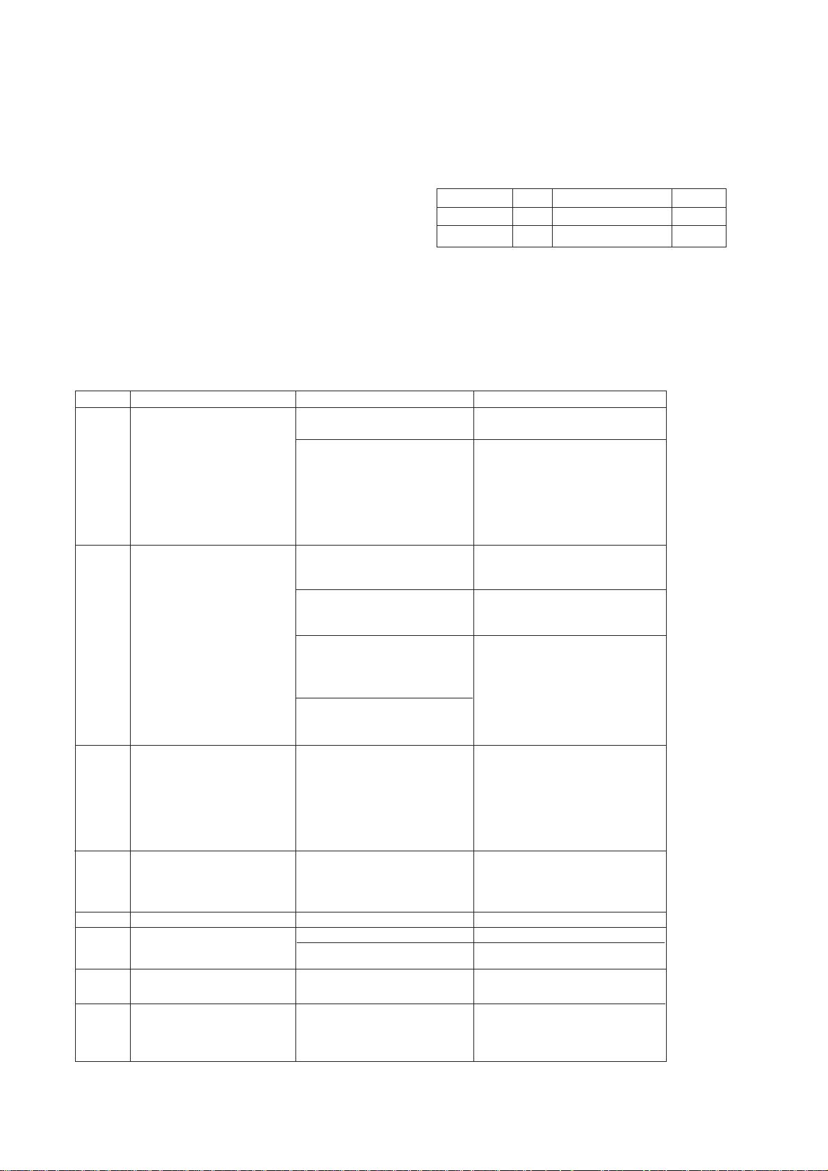
Item
X
Y
Color
Temperature
288
295
9000
degree
268
273
1300
degree
267
276
1300
degree
282
288
10000
degree
266
282
13000
degree
EU
N-EU
KOREA
/Taiwan
Middle/South
America
Philippines
<Table 1> WHITE BALANCE Color Coordinate
Item
BLO-R(R CUT)
BLO-G(G CUT)
RG(R DRIVE)
GG(G DRIVE)
BG (B DRIVE)
LOW
LIGHT
HIGH
LIGHT
0 ~ 63
0 ~ 63
0 ~ 63
0 ~ 63
0 ~ 63
32
32
32
32
32
PAL
fixed
Range
default setting data
remarks
<Table 2> WHITE BALANCE default setting data
<Table 3>W/B auto adjust machine setting Table
VCD IC
EP_ROM
Name
Maker
NOTE
Program
Vcd Slave
Win31_wb
TWB
8A
Eeprom_Slave
Win31_wb
TWB
A0
Speed1Delay
30
SPEED/PLUS
2
22
2
G_Cut
Win31_wb TWB
18
5
0
0
0
34
Mode
High
Light
Low
Light
0 0 0 0
Algorithm
Copyright©2009 LG Electronics.Inc. All right reserved.
Only for training and service purposes.
LGE Internal Use Only
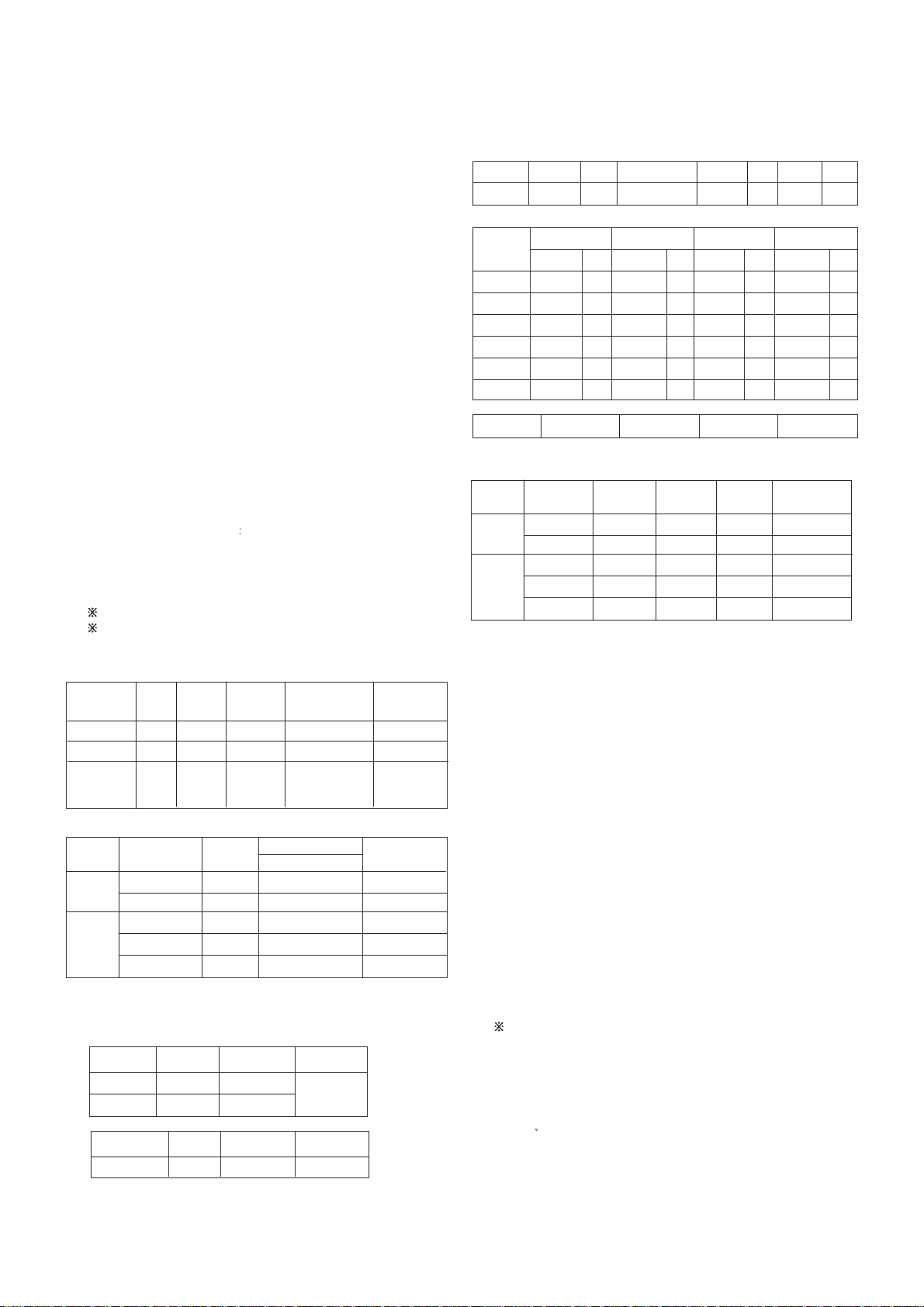
4. V AMPLIT (V AMPITUDE)
PAL signal: Adjust upper and lower part of circle from the effective
screen of the CPT to be distance of 6~7mm .
5. H SHIFT (HS)
Adjust the vertical center line of a digital circle pattern is in accord
with geometric vertical center of the CPT.
6. EW WIDTH (EW)
Adjust outer line of the left/right outer lattice to be united with
effective boundary surface of CPT.
Adjust of [Fig 4] 0~25% scope on external lattice from PAL
adjustment.
7. EW PARAB (EW PARABOLA)
Adjust so that middle portion of the outer most left and
right vertical line looks like parallel with vertical lines of the
CPT.
8. EW TRAPE (EW TRAPEZOID)
Keep accord with the top and the undersurface horizontal scope.
(When picture distorts,adjust until it is the square.)
9. EW UPCOR & EW LOCORR
Adjust so that corner vertical line of upper-left ,upper-right, lower-
left and lower-right to be optimization.
10. H BOW
Adjust until distortion scope of the edge part in the top and the
undersurface of the picture are the same.
11. H PARALL (ANGLE)
In angle adjustment, adjust until inclination of center vertical line
should be vertical precisely.
12. SCORRECT (S CORRECTION)
Adjust so that the lattice scopes of top, center, bottom of received
pattern are the same.
Use the default setting data (Initial data) of CPT owing to using DY
data of CPT.
13. V SCROLL
Keep accord with the geometry vertical center line of received
picture and the vertical center of CPT.
14. V ZOOM
VERTICAL ZOOM
15. WBR
16. WBF
17. PIP_ H (PIP H Position) Adjustment* - option
In PAL Channel (E5 CH), when adjust PIP_H position, it will
automatic convert into Double Window Mode.
PIP H Position adjust stand-by picture state, use VOL+, - KEY to
move H-Position or V-Position of sub-picture.
When PIP picture and main picture connect, press VOL+ KEY to
adjust.
3.5 Deflection setting default
- P A L
[Table 4] Deflection setting default based on different model
(SERVICE 2)
- 7 -
[Fig.5] Cross-Hatch Pattern (PAL:E-7 CH)
CRNU
CRNL
CRNU6
EP
CRNL6
Adjusting Point
Actual picture size
[fig.4] PAL Digital Pattern (EU05CH)
[Fig.5] PIP H Position Adjust Picture
Copyright©2009 LG Electronics.Inc. All right reserved.
Only for training and service purposes.
LGE Internal Use Only
 Loading...