

LG 29LN450B, 29LN450U, 29LN457B, 29LN457U, 29LN4503 Service manual
...
Internal Use Only
North/Latin America http://aic.lgservice.com
Europe/Africa http://eic.lgservice.com
Asia/Oceania http://biz.lgservice.com
LED TV
SERVICE MANUAL
CHASSIS : LA31R / LD31S
MODEL : 29LN45** 29LN45**-Z*
CAUTION
BEFORE SERVICING THE CHASSIS,
READ THE SAFETY PRECAUTIONS IN THIS MANUAL.
Printed in KoreaP/NO : MFL67862501 (1304-REV00)

CONTENTS
CONTENTS .............................................................................................. 2
SAFETY PRECAUTIONS ........................................................................ 3
SERVICING PRECAUTIONS ................................................................... 4
SPECIFICATION ...................................................................................... 6
ADJUSTMENT INSTRUCTION ............................................................... 9
TROUBLE SHOOTING .......................................................................... 15
BLOCK DIAGRAM ................................................................................. 19
EXPLODED VIEW .................................................................................. 20
SCHEMATIC CIRCUIT DIAGRAM ..............................................................
Only for training and service purposes
- 2 -
LGE Internal Use OnlyCopyright © LG Electronics. Inc. All rights reserved.
SAFETY PRECAUTIONS
IMPORTANT SAFETY NOTICE
Many electrical and mechanical parts in this chassis have special safety-related characteristics. These parts are identified by in the
Schematic Diagram and Exploded View.
It is essential that these special safety parts should be replaced with the same components as recommended in this manual to prevent
Shock, Fire, or other Hazards.
Do not modify the original design without permission of manufacturer.
General Guidance
An isolation Transformer should always be used during the
servicing of a receiver whose chassis is not isolated from the AC
power line. Use a transformer of adequate power rating as this
protects the technician from accidents resulting in personal injury
from electrical shocks.
It will also protect the receiver and it's components from being
damaged by accidental shorts of th e cir cuitry that may be
inadvertently introduced during the service operation.
If any fuse (or Fusible Resistor) in this TV receiver is blown,
replace it with the specified.
When replacing a high wattage resistor (Oxide Metal Film Resistor,
over 1 W), keep the resistor 10 mm away from PCB.
Keep wires away from high voltage or high temperature parts.
Before returning the receiver to the customer,
always perform an AC leakage current check on the exposed
metallic parts of the cabinet, such as antennas, terminals, etc., to
be sure the set is safe to operate without damage of electrical
shock.
Leakage Current Cold Check(Antenna Cold Check)
With the instrument AC plug removed from AC source, connect an
electrical jumper across the two AC plug prongs. Place the AC
switch in the on position, connect one lead of ohm-meter to the AC
plug prongs tied together and touch other ohm-meter lead in turn to
each exposed metallic parts such as antenna terminals, phone
jacks, etc.
If the exposed metallic part has a return path to the chassis, the
measured resistance should be between 1 MΩ and 5.2 MΩ.
When the exposed metal has no return path to the chassis the
reading must be infinite.
An other abnormality exists that must be corrected before the
receiver is returned to the customer.
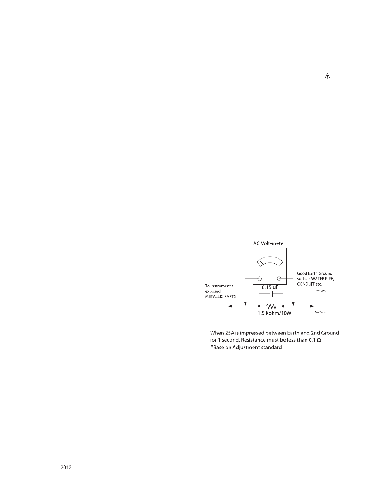
Leakage Current Hot Check (See below Figure)
Plug the AC cord directly into the AC outlet.
Do not use a line Isolation Transformer during this check.
Connect 1.5 K / 10 watt resistor in parallel with a 0.15 uF capacitor
between a known good earth ground (Water Pipe, Conduit, etc.)
and the exposed metallic parts.
Measure the AC voltage across the resistor using AC voltmeter
with 1000 ohms/volt or more sensitivity.
Reverse plug the AC cord into the AC outlet and repeat AC voltage
measurements for each exp ose d metallic par t. Any voltage
measured must not exceed 0.75 volt RMS which is corresponds to
0.5 mA.
In case any measurement is out of the limits specified, there is
possibility of shock hazard and the set must be checked and
repaired before it is returned to the customer.
Leakage Current Hot Check circuit
Only for training and service purposes
- 3 -
LGE Internal Use OnlyCopyright © LG Electronics. Inc. All rights reserved.

SERVICING PRECAUTIONS
CAUTION: Before servicing receivers covered by this service
manual and its supplements and addenda, read and follow the
SAFETY PRECAUTIONS on page 3 of this publication.
NOTE: If unforeseen circumstances create conict between the
following servicing precautions and any of the safety precautions
on page 3 of this publication, always follow the safety precautions. Remember: Safety First.
General Servicing Precautions
1. Always unplug the receiver AC power cord from the AC power
source before;
a. Removing or reinstalling any component, circuit board
module or any other receiver assembly.
b. Disconnecting or reconnecting any receiver electrical plug
or other electrical connection.
c. Connecting a test substitute in parallel with an electrolytic
capacitor in the receiver.
CAUTION: A wrong part substitution or incorrect polarity
installation of electrolytic capacitors may result in an explosion hazard.
2. Test high voltage only by measuring it with an appropriate
high voltage meter or other voltage measuring device (DVM,
FETVOM, etc) equipped with a suitable high voltage probe.
Do not test high voltage by "drawing an arc".
3. Do not spray chemicals on or near this receiver or any of its
assemblies.
4. Unless specied otherwise in this service manual, clean
electrical contacts only by applying the following mixture to the
contacts with a pipe cleaner, cotton-tipped stick or comparable
non-abrasive applicator; 10 % (by volume) Acetone and 90 %
(by volume) isopropyl alcohol (90 % - 99 % strength)
CAUTION: This is a ammable mixture.
Unless specied otherwise in this service manual, lubrication
of contacts in not required.
5. Do not defeat any plug/socket B+ voltage interlocks with which
receivers covered by this service manual might be equipped.
6. Do not apply AC power to this instrument and/or any of its
electrical assemblies unless all solid-state device heat sinks
are correctly installed.
7. Always connect the test receiver ground lead to the receiver
chassis ground before connecting the test receiver positive
lead.
Always remove the test receiver ground lead last.
8. Use with this receiver only the test xtures specied in this
service manual.
CAUTION: Do not connect the test xture ground strap to any
heat sink in this receiver.
Electrostatically Sensitive (ES) Devices
Some semiconductor (solid-state) devices can be damaged easily by static electricity. Such components commonly are called
Electrostatically Sensitive (ES) Devices. Examples of typical ES
devices are integrated circuits and some eld-effect transistors
and semiconductor “chip” components. The following techniques
should be used to help reduce the incidence of component damage caused by static by static electricity.
1. Immediately before handling any semiconductor component or
semiconductor-equipped assembly, drain off any electrostatic
charge on your body by touching a known earth ground. Alternatively, obtain and wear a commercially available discharging wrist strap device, which should be removed to prevent
potential shock reasons prior to applying power to the unit
under test.
2. After removing an electrical assembly equipped with ES
devices, place the assembly on a conductive surface such as
aluminum foil, to prevent electrostatic charge buildup or exposure of the assembly.
3. Use only a grounded-tip soldering iron to solder or unsolder
ES devices.
4. Use only an anti-static type solder removal device. Some solder removal devices not classied as “anti-static” can generate
electrical charges sufcient to damage ES devices.
5. Do not use freon-propelled chemicals. These can generate
electrical charges sufcient to damage ES devices.
6. Do not remove a replacement ES device from its protective
package until immediately before you are ready to install it.
(Most replacement ES devices are packaged with leads electrically shorted together by conductive foam, aluminum foil or
comparable conductive material).
7. Immediately before removing the protective material from the
leads of a replacement ES device, touch the protective material to the chassis or circuit assembly into which the device will
be installed.
CAUTION: Be sure no power is applied to the chassis or circuit, and observe all other safety precautions.
8. Minimize bodily motions when handling unpackaged replacement ES devices. (Otherwise harmless motion such as the
brushing together of your clothes fabric or the lifting of your
foot from a carpeted oor can generate static electricity sufcient to damage an ES device.)
General Soldering Guidelines
1. Use a grounded-tip, low-wattage soldering iron and appropriate tip size and shape that will maintain tip temperature within
the range or 500 °F to 600 °F.
2. Use an appropriate gauge of RMA resin-core solder composed
of 60 parts tin/40 parts lead.
3. Keep the soldering iron tip clean and well tinned.
4. Thoroughly clean the surfaces to be soldered. Use a mall wirebristle (0.5 inch, or 1.25 cm) brush with a metal handle.
Do not use freon-propelled spray-on cleaners.
5. Use the following unsoldering technique
a. Allow the soldering iron tip to reach normal temperature.
(500 °F to 600 °F)
b. Heat the component lead until the solder melts.
c. Quickly draw the melted solder with an anti-static, suction-
type solder removal device or with solder braid.
CAUTION: Work quickly to avoid overheating the circuit
board printed foil.
6. Use the following soldering technique.
a. Allow the soldering iron tip to reach a normal temperature
(500 °F to 600 °F)
b. First, hold the soldering iron tip and solder the strand
against the component lead until the solder melts.
c. Quickly move the soldering iron tip to the junction of the
component lead and the printed circuit foil, and hold it there
only until the solder ows onto and around both the component lead and the foil.
CAUTION: Work quickly to avoid overheating the circuit
board printed foil.
d. Closely inspect the solder area and remove any excess or
splashed solder with a small wire-bristle brush.
Only for training and service purposes
- 4 -
LGE Internal Use OnlyCopyright © LG Electronics. Inc. All rights reserved.

IC Remove/Replacement
Some chassis circuit boards have slotted holes (oblong) through
which the IC leads are inserted and then bent at against the circuit foil. When holes are the slotted type, the following technique
should be used to remove and replace the IC. When working with
boards using the familiar round hole, use the standard technique
as outlined in paragraphs 5 and 6 above.
Removal
1. Desolder and straighten each IC lead in one operation by
gently prying up on the lead with the soldering iron tip as the
solder melts.
2. Draw away the melted solder with an anti-static suction-type
solder removal device (or with solder braid) before removing
the IC.
Replacement
1. Carefully insert the replacement IC in the circuit board.
2. Carefully bend each IC lead against the circuit foil pad and
solder it.
3. Clean the soldered areas with a small wire-bristle brush.
(It is not necessary to reapply acrylic coating to the areas).
"Small-Signal" Discrete Transistor
Removal/Replacement
1. Remove the defective transistor by clipping its leads as close
as possible to the component body.
2. Bend into a "U" shape the end of each of three leads remaining on the circuit board.
3. Bend into a "U" shape the replacement transistor leads.
4. Connect the replacement transistor leads to the corresponding
leads extending from the circuit board and crimp the "U" with
long nose pliers to insure metal to metal contact then solder
each connection.
Power Output, Transistor Device
Removal/Replacement
1. Heat and remove all solder from around the transistor leads.
2. Remove the heat sink mounting screw (if so equipped).
3. Carefully remove the transistor from the heat sink of the circuit
board.
4. Insert new transistor in the circuit board.
5. Solder each transistor lead, and clip off excess lead.
6. Replace heat sink.
Diode Removal/Replacement
1. Remove defective diode by clipping its leads as close as possible to diode body.
2. Bend the two remaining leads perpendicular y to the circuit
board.
3. Observing diode polarity, wrap each lead of the new diode
around the corresponding lead on the circuit board.
4. Securely crimp each connection and solder it.
5. Inspect (on the circuit board copper side) the solder joints of
the two "original" leads. If they are not shiny, reheat them and
if necessary, apply additional solder.
3. Solder the connections.
CAUTION: Maintain original spacing between the replaced
component and adjacent components and the circuit board to
prevent excessive component temperatures.
Circuit Board Foil Repair
Excessive heat applied to the copper foil of any printed circuit
board will weaken the adhesive that bonds the foil to the circuit
board causing the foil to separate from or "lift-off" the board. The
following guidelines and procedures should be followed whenever this condition is encountered.
At IC Connections
To repair a defective copper pattern at IC connections use the
following procedure to install a jumper wire on the copper pattern
side of the circuit board. (Use this technique only on IC connections).
1. Carefully remove the damaged copper pattern with a sharp
knife. (Remove only as much copper as absolutely necessary).
2. carefully scratch away the solder resist and acrylic coating (if
used) from the end of the remaining copper pattern.
3. Bend a small "U" in one end of a small gauge jumper wire and
carefully crimp it around the IC pin. Solder the IC connection.
4. Route the jumper wire along the path of the out-away copper
pattern and let it overlap the previously scraped end of the
good copper pattern. Solder the overlapped area and clip off
any excess jumper wire.
At Other Connections
Use the following technique to repair the defective copper pattern
at connections other than IC Pins. This technique involves the
installation of a jumper wire on the component side of the circuit
board.
1. Remove the defective copper pattern with a sharp knife.
Remove at least 1/4 inch of copper, to ensure that a hazardous
condition will not exist if the jumper wire opens.
2. Trace along the copper pattern from both sides of the pattern
break and locate the nearest component that is directly connected to the affected copper pattern.
3. Connect insulated 20-gauge jumper wire from the lead of the
nearest component on one side of the pattern break to the
lead of the nearest component on the other side.
Carefully crimp and solder the connections.
CAUTION: Be sure the insulated jumper wire is dressed so the
it does not touch components or sharp edges.
Fuse and Conventional Resistor
Removal/Replacement
1. Clip each fuse or resistor lead at top of the circuit board hollow
stake.
2. Securely crimp the leads of replacement component around
notch at stake top.
Only for training and service purposes
- 5 -
LGE Internal Use OnlyCopyright © LG Electronics. Inc. All rights reserved.
SPECIFICATION
NOTE : Specifications and others are subject to change without notice for improvement
.
1. Application range
This specification is applied to the LED TV used LA31R /
LD31S chassis.
2. Requirement for Test
Each part is tested as below without special appointment.
1) Temperature: 25 °C ± 5 °C(77 °F ± 9 °F), CST: 40 °C ± 5 °C
2) Relative Humidity: 65 % ± 10 %
3) Power Voltage
: Standard input voltage (AC 100-240 V~, 50/60 Hz)
* Standard Voltage of each products is marked by models.
4) Specification and performance of each parts are followed
ea ch drawing and s pe cificatio n b y p art number in
accordance with BOM.
5) The receiver must be operated for about 5 minutes prior to
the adjustment.
3. Test method
1) Performance: LGE TV test method followed
2) Demanded other specification
- Safety : CE, IEC specification
- EMC : CE, IEC
4. Model General Specification
No. Item Specication Remarks
DTV & Analog (Total 37 countries)
DTV (MPEG2/4, DVB-T) :37 countries
UK/Italy/Germany/France/Spain/Sweden/Finland/Netherlands/
Belgium/Luxemburg/ Greece/Denmark/Czech/Austria/Hungary
/Swiss/Croatia/Turkey/Norway/Slovenia/Poland/Ukraine/Portugal/Ireland/Morocco/Latvia/Estonia/Lithania/Rumania/Bulgaria/
Russia/SlovakiaBosnia/Serbia/Albania/Kazakhstan/Belarus
*4 Country, Nordic option(EU model only)
- Denmark , Finland, Norway, Sweden
1 Market EU/CIS(PAL Market-37 Countries)
DTV (MPEG2/4, DVB-T2): 8 countries
UK/Denmark/Sweden/Finland/Norway/Ireland/Ukraine/Kazakhstan
DTV (MPEG2/4, DVB-C): 37 countries
UK/Italy/Germany/France/Spain/Sweden/Finland/Netherlands/
Belgium/Luxemburg/ Greece/Denmark/Czech/Austria /Hungary/Swiss/Croatia/Turkey/Norway/Slovenia/Poland/Ukraine/
Portugal/Ireland/Morocco/Latvia/Estonia/Lithania/Rumania/
Bulgaria/Russia/Slovakia/Bosnia/Serbia/Albania/Kazakhstan/
Belarus
DTV (MPEG2/4,DVB-S): 29 countries
Italy/Germany/France/Spain/Netherlands/ Belgium/Luxemburg/
Greece/ Czech/Austria /Hungary/Swiss/Croatia/Turkey/Slovenia/Poland/Portugal/ Morocco/Latvia/Estonia/Lithuania/Rumania/Bulgaria/Russia/SlovakiaBosnia/Serbia/Albania/ Belarus
Supported satellite : 22 satellites
HISPASAT 1C/1D, ATLANTIC BIRD 2, NILESAT 101/102,
ATLANTIC BIRD 3, AMOS 2/3, THOR 5/6, IRIUS 4, EUTELSAT-W3A, EUROBIRD 9A, EUTELSAT-W2A, HOTBIRD 6/8/9,
EUTELSAT-SESAT, ASTRA 1L/H/M/KR, ASTRA 3A/3B, BADR
4/6, ASTRA 2D, EUROBIRD 3, EUTELSAT-W7, HELLASSAT
2, EXPRESS AM1, TURKSAT 2A/3A, INTERSAT10
Only for training and service purposes
- 6 -
LGE Internal Use OnlyCopyright © LG Electronics. Inc. All rights reserved.
No. Item Specication Remarks
Analogue TV
1) PAL-BG
2) PAL-DK
3) PAL-I/I’
4) SECAM-BG
5) SECAM-DK
2 Broadcasting system
3 Receiving system
4 Scart Jack (1EA) PAL, SECAM Scart 1 Jack is Full scart and support RF-OUT(analog).
5 Component Input (1EA) Y/Pb/Pr
6 CVBS Input (1EA) PAL, SECAM, NTSC
7 RGB Input RGB-PC Analog(D-SUB 15PIN)
8 HDMI Input (1EA) HDMI
9 Audio Input (3EA)
10 Headphone out (1EA) Antenna, AV, Component, RGB, HDMI Side 1EA
11 USB (1EA) Picture, Music, Movie, SVC Software Update + Picture + Music + Movie
12 DVB
13 Local Key (Touch)
14 LAN JACK Modular Only UK model
6) SECAM L/L’
Digital TV
1) DVB-T/C/T2
Satellite Digital TV
1) DVB-T/C/S/S2
Analog : Upper Heterodyne
Digital : COFDM, QAM
RGB/DVI Audio
Component & CVBS
SCART
DVB-T
DVB-C
Analogue TV : (RF) VHF: E2 to E12, UHF : E21 to E69
(CATV) S1 to S20, HYPER: S21 to S47
Digital TV : VHF, UHF
Satellite TV : VHF, UHF,
C-Band, Ku-Band
* DVB-T2 ( T2 model only support )
* DVB-S/S2 (Satellite model only support )
► DVB-T
- Guard Interval(Bitrate_Mbit/s)B : 1/4, 1/8, 1/16, 1/32
- Modulation : Code Rate
QPSK : 1/2, 2/3, 3/4, 5/6, 7/8
16-QAM : 1/2, 2/3, 3/4, 5/6, 7/8
64-QAM : 1/2, 2/3, 3/4, 5/6, 7/8
► DVB-T2
- Guard Interval(Bitrate_Mbit/s)
1/4, 1/8, 1/16, 1/32, 1/128, 19/128, 19/256,
- Modulation : Code Rate
QPSK : 1/2, 2/5, 2/3, 3/4, 5/6
16-QAM : 1/2, 2/5, 2/3, 3/4, 5/6
64-QAM : 1/2, 2/5, 2/3, 3/4, 5/6
256-QAM : 1/2, 2/5, 2/3, 3/4, 5/6
► DVB-C
- Symbolrate : 4.0Msymbols/s to 7.2Msymbols/s
- Modulation : 16QAM, 64-QAM, 128-QAM and 256-QAM
► DVB-S/S2
- symbolrate
DVB-S2 (8PSK / QPSK) : 2 ~ 45 Msymbol/s
DVB-S (QPSK) : 2 ~ 45 Msymbol/s
- viterbi
DVB-S mode : 1/2, 2/3, 3/4, 5/6, 7/8
DVB-S2 mode : 1/2, 2/3, 3/4, 3/5, 4/5, 5/6, 8/9, 9/10
4 System(Rear) : PAL, SECAM, NTSC, PAL60
CVBS Video input is used by common port with Component.
Rear1EA / HDMI version 1.4/ support PC
Support HDCP/HDMI : MHL Support
L/R Input
CVBS Audio input is used by common port with Component.
CI : UK, Finland, Denmark, Norway, Sweden, Russia, Spain,
Ireland, Luxemburg, Belgium, Netherland
CI+ : France(Canal+), Italy(DGTVi)
CI : Switzerland, Austria, Slovenia, Hungary, Bulgaria
CI+: Switzerland(UPC,Cablecom), Netherland(Ziggo),
Germany(KDG,CWB), Finland(labwise)
Only for training and service purposes
- 7 -
LGE Internal Use OnlyCopyright © LG Electronics. Inc. All rights reserved.
5. Timing
5.1. RGB/HDMI (PC)
No.
1. 720*400 31.468 70.080 28.321
2. 640*480 31.469 59.940 25.175
3. 640*480 37.500 75.000 31.500
4. 800*600 37.879 60.317 40.000
5. 800*600 46.875 75.000 49.500
6. 1024*768 48.363 60.004 65.000
7. 1024*768 60.023 75.029 78.750
8. 1280*800 49.702 59.810 83.500
9. 1366*768 47.717 59.79 85.5
Resolution H-freq(kHz) V-freq.(Hz) Pixel clock(MHz)
5.2. HDMI (DTV)
Specication
Remark
No.
1. 720*480
2. 720*576 31.250 50.000 27.864 SDTV 576P
3. 1280*720 37.500 50.000 74.250 HDTV 720P
4. 1280*720
5. 1920*1080
6. 1920*1080 28.125 50.000 74.250 HDTV 1080I
7. 1920*1080 27.000 24.000 74.250 HDTV 1080P
8. 1920*1080 33.750 30.000 74.250 HDTV 1080P
9. 1920*1080 56.250 50.000 148.500 HDTV 1080P
10. 1920*1080
Resolution H-freq(kHz) V-freq.(Hz) Pixel clock(MHz)
31.469
31.5000
44.960
45.000
33.720
33.750
67.430
67.500
Specication
59.940
60.000
59.940
60.000
59.940
60.000
59.940
60.000
27.000
27.030
74.170
74.250
74.170
74.250
148.350
148.500
Remark
SDTV 480P
HDTV 720P
HDTV 1080I
HDTV 1080P
Only for training and service purposes
- 8 -
LGE Internal Use OnlyCopyright © LG Electronics. Inc. All rights reserved.
5.3. Component
No.
1. 720*480 15.730 59.940 13.500 SDTV, DVD 480I(525I)
2. 720*480 15.750 60.000 13.514 SDTV, DVD 480I(525I)
3. 720*576 15.625 50.000 13.500 SDTV, DVD 576I(625I) 50Hz
4. 720*480 31.470 59.940 27.000 SDTV 480P
5. 720*480 31.500 60.000 27.027 SDTV 480P
6. 720*576 31.250 50.000 27.000 SDTV 576P 50Hz
7. 1280*720 44.960 59.940 74.176 HDTV 720P
8. 1280*720 45.000 60.000 74.250 HDTV 720P
9. 1280*720 37.500 50.000 74.250 HDTV 720P 50Hz
10. 1920*1080 33.720 59.940 74.176 HDTV 1080I
11. 1920*1080 33.750 60.000 74.250 HDTV 1080I
12. 1920*1080 28.125 50.000 74.250 HDTV 1080I 50Hz,
13. 1920*1080 56.250 50.000 148.500 HDTV 1080P
14. 1920*1080 67.432 59.940 148.350 HDTV 1080P
15. 1920*1080 67.500 60.000 148.500 HDTV 1080P
Resolution H-freq(kHz) V-freq.(Hz) Pixel clock(MHz)
Specication
Remark
Only for training and service purposes
- 9 -
LGE Internal Use OnlyCopyright © LG Electronics. Inc. All rights reserved.
ADJUSTMENT INSTRUCTION
(2)
(6)
1. Application Range
This document is applied to LA31R / LD31S chassis LED TV
which is manufactu red in TV( or Mo nit or) Factory or is
produced on the basis of this data.
2. Designation
(1) Th e ad justm ent is accord ing to the order whic h is
designated and which must be followed, according to the
plan which can be changed only on agreeing.
(2) Power adjustment : Free Voltage.
(3) Magnetic Field Condition: Nil.
(4) Input signal Unit: Product Specification Standard.
(5) Reserve after operation: Above 5 Minutes (Heat Run)
Temperature : at 25 °C ± 5 °C
Relative humidity : 65 % ± 10 %
Input voltage : 110-240 V, 50/60 Hz
(6) Adjustment equipments: Color Analyzer(CA-210 or CA-110),
DDC Adjustment Jig equipment, Service remote control.
(7) Push The "IN STOP KEY" – For memory initialization
Case1 : Software version up
1. After downloading S/W by USB , TV set will reboot
automatically.
2. Push “In-stop” key.
3. Push “Power on” key.
4. Function inspection
5. After function inspection, Push “In-stop” key.
Case2 : Function check at the assembly line
1. When TV set is entering on the assembly line, Push
“In-stop” key at rst.
2. Push “Power on” key for turning it on.
→ If you push “Power on” key, TV set will recover
channel information by itself.
3. After function inspection, Push “In-stop” key.
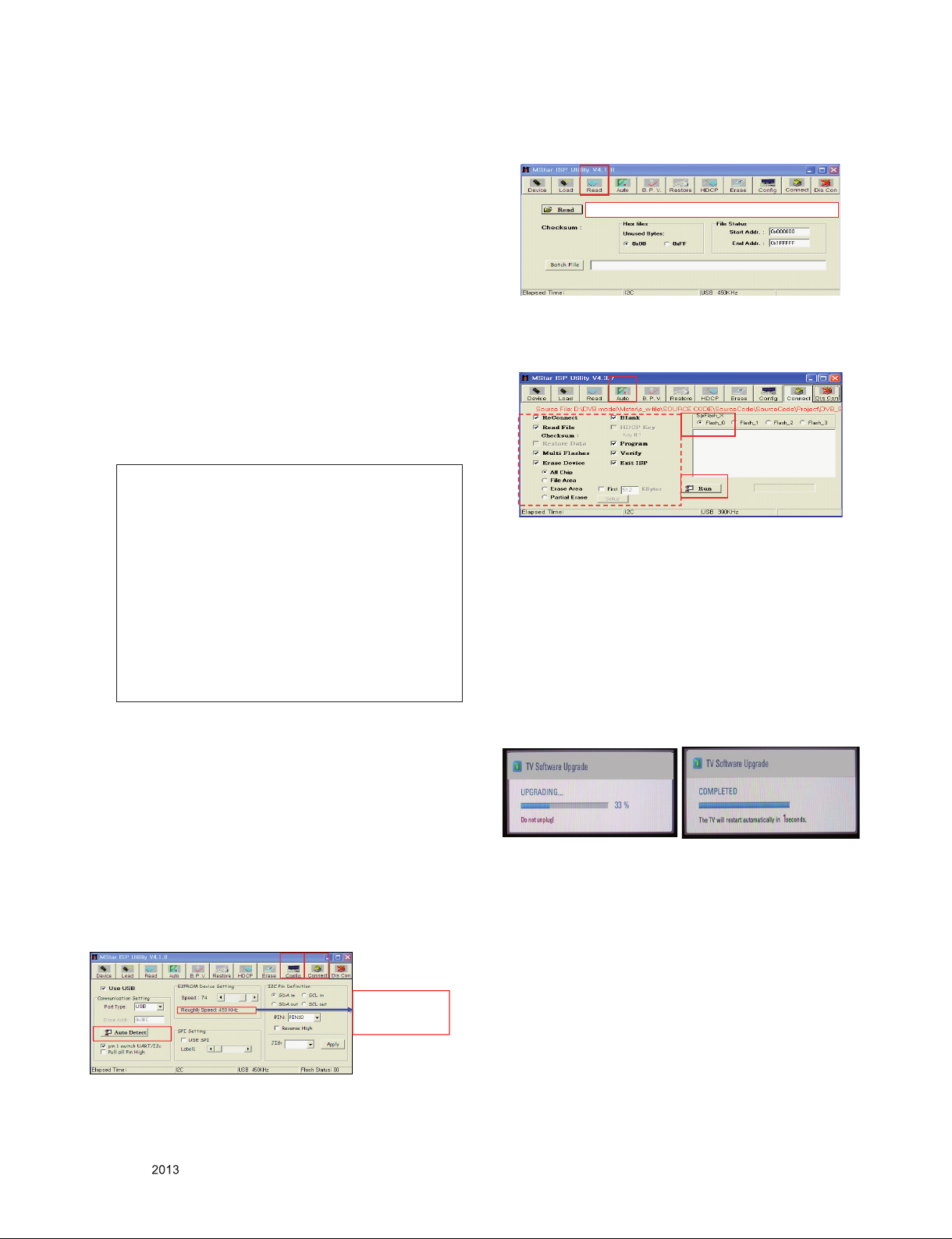
(4) Click “Read” tab, and then load download file(XXXX.bin)
by clicking “Read”.
(4)
filexxx.bin
(5) Click “Auto” tab and set as below
(6) Click “Run”.
(7) After downloading, check “OK” message.
(5)
(5)
(7) ……….OK
* USB DOWNLOAD(*.epk file download)
(1) Make New folder named “LG_DTV” and put ISP file(*.epk)
in the folder.
(2) Put the USB Stick to the USB socket.
(3) Automatically detecting update file in USB Stick
- If your downloaded program version in USB Stick is Low,
it didn’t work.
- Bu t your downloaded version is High, USB data is
automatically detecting
(4) Show the message "Copying files from memory"
(5) Updating is starting.
3. Main PCB check process
* APC - After Manual-Insult, executing APC
* Boot le Download
(1) Execute ISP program “Mstar ISP Utility” and then click
“Config” tab.
(2) Set as below, and then click “Auto Detect” and check “OK”
message. If display “Error”, Check connect computer, jig,
and set.
(3) Click “Connect” tab. If display “Can’t”, Check connect
computer, jig, and set.
(1) (3)
Please Check the Speed :
Use the speed under
OK
Only for training and service purposes
200KHz.
- 10 -
(6) Updating C om pl et ed , T he Multi-vi si on will r es ta rt
automatically.
(7) If your TV is turned on, check your updated version and
Tool option. (explain the Tool option, next stage)
* If downloading version is more high than your TV have,
TV can lost all channel data. In this case, you have to
channel recover. if all channel data is cleared, you didn’t
have a DTV/ATV test on production line.
* After downloading, have to adjust TOOL OPTION again.
(1) Push "ADJ" key in service remote control.
(2) Select "Tool Option 1" and push "OK" key.
(3) Punch in the number. (Each model has their number.)
(4) Completed selecting Tool option.
LGE Internal Use OnlyCopyright © LG Electronics. Inc. All rights reserved.
3.1. EDID Process
3.1.1. EDID download
(1) Press "Power only" key of service remote control.
(2) Press the ADJ KEY on R/C and enter EZ ADJUST
(3) Enter EDID D/L mode by pushing "►" key at "11. EDID D/L".
(4) EDID download is executed automatically.
(5) Press EXIT key on service remote control.
<Caution>
- Never connect HDMI & D-sub Cable when download EDID.
- Download HDMI
* Edid data and Model option download (USB)
NO Item CMD 1 CMD 2 Data 0
Enter download
MODE
EDID data and
Model option
download
3.1.2. RGB EDID Data
(1) All models without 29MN33D(Product ID: 22984/HEXA: 59C8)
EZ ADJUST
0. Tool Option1
1. Tool Option2
2. Tool Option3
3. Tool Option4
4. Tool Option5
5. Tool Option6
6. Country Group
7. Area Option
8. ADC Calibration
9. White Balance
10. 10 Point WB
11. Test Pattern
12. EDID D/L ►
14. Touch Sensitivity Setting
15. Ext. Input Adjust
16. SPK Lipsync Adjust
17.SPDIF Lipsync Adjust
Download
‘Mode In’
Download A E 00 10 Automatically download
A A 0 0 When transfer the ‘Mode
EDID D/L
HDMI OK
RGB OK
Reset
Start
In’, Carry the command.
(The use of a internal Data)
3.2. Function Check
3.2.1. Check display and sound
*Check Input and Signal items. (cf. work instructions)
(1) TV
(2) AV (SCART/CVBS)
(3) COMPONENT (480i)
(4) RGB(PC : 1366 x 768 @ 60Hz)
(5) HDMI(PC : 1366 x 768 @ 60Hz)
(6) PC Audio In
* Display and Sound check is executed by Remote control
<Caution> Not to push the INSTOP key after completion if the
function inspection.
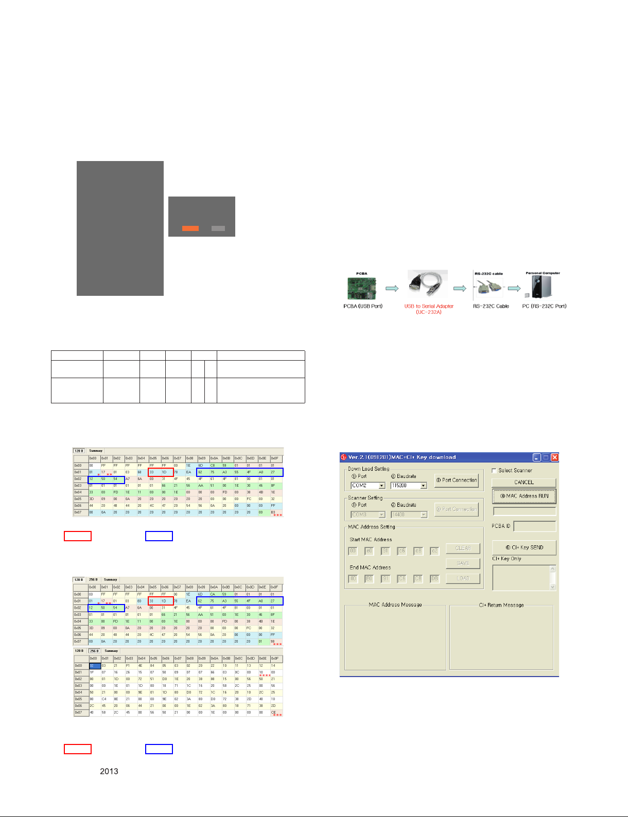
3.3. CI+ key writing process. (Device CN)
3.3.1. Communication Port Connection
Connection : PCBA (USB Port) → USB to Serial Adapter
(UC-232A) → RS-232C cable → PC(RS-232C port)
* Caution: LD31Q/LD31 A chassis sup port only UC-23 2A
driver. (only use this one)
3.3.2. CI+ Key Download
(1) Set CI+ Key path Directory at Start Mac & CI+ Download
Programme.
(2) Set COM 1,2,3,4 / 115200(Baudrate) (1)/(2)
(3) Click port connection button(1)
(4) Start CI+ Key Download, Push the button(4)
(5) Check OK or NG
*(week), **(year), ***(Check sum) : Adjustable Data
: Screen size, : Color Characteristics
3.1.3. HDMI EDID Data
(1) All models(Product ID: 22986/HEXA:59CA)
*(week), **(year), ***(Check sum) : Adjustable Data
**** (physical address): (HDMI : 10), ****(Check sum): (HDMI : CE)
: Screen size, : Color Characteristics
Only for training and service purposes
- 11 -
(6) After completing download, CI + key values are increase
by one automatically. To write CI+ key next SET, click CI+
key writing button(5) directly.
(7) Check whether the key was downloaded or not at ‘In Start’
menu. (Refer to below).
LGE Internal Use OnlyCopyright © LG Electronics. Inc. All rights reserved.
 Loading...