How it Works
Log In / Sign Up
Buy Points
How it Works
FAQ
Contact Us
Questions and Suggestions
Users
LG
Loading...
#
26LG40
31
26LG4000
17
26LG4000-ZA
3
26LG40 Series
26LG40-UA
3
26LG40UG
4
26LG5
26LH1DC1
3
26LH1DC1-UB
2
26LH1DC3
26LH1DC3 - - 26"" LCD TV
26LH1DC3-UA
26LH1DC4
3
26LH1DC4-UB
26LH1DC5
3
26LH1DC5-UC
26LH2
5
26LH20
36
26LH2000
15
26LH2000-ZA
26LH200C
7
26LH200C-TA
26LH200CUA
26LH200H
7
26LH200H-ZA
26LH200H-ZB
26LH2010
3
26LH2010-ZB
26LH201C
5
26LH2020
2
26LH2020-ZC
26LH20 - - 26"" LCD TV
26LH20D
26LH20R
18
26LH20R-LA/TA
26LH20R-MA
2
26LH20 Series
2
26LH20-UA
4
26LH210C
4
26LH210C-TA
26LH220C-TA
26LH250C
10
26LH250C-ZA
26LH250C-ZB
26LH2 Series
6
26LJ620H
2
26LK3
2
26LK310
9
26LK310-TA
2
26LK310Y
4
26LK310Y-TA
26LK310Z
2
26LK311
8
26LK311C
2
26LK311-TB
3
26LK313
26LK33
2
26LK330
31
26LK330A
26LK330A-ZB
26LK330N
2
26LK330N-ZB
26LK330U
2
26LK330UB
26LK330UH
26LK330U-ZB
26LK330-ZB
26LK3310Y-TA
26LK331-ZA
26LK332
26LK33,42LK43,32LK45
26LK335C
4
26LK335C-ZB
26LK336C
3
26LK33 Series
4
26LK3 Series
26LN4100
26LN4130
4
26LN4130-TD
2
26LN4140
26LN45
26LN4500
9
26LN4500UAAUSHLJM
26LN4500-ZA
2
26LN4503
4
26LN4503-ZB
26LN4505
3
26LN4505-ZB
26LN450B
22
26LN450B-ZB
2
26LN450R-ZB
2
26LN450U
6
26LN450U-ZB
2
26LN4573
26LN4573-ZI
26LN4575
26LN4575-ZI
26LN457B
7
26LN457B-ZI
26LN457R-ZI
Loading...
Loading...
Nothing found
26LK310Y
Service Manual
28 pgs
2.22 Mb
0
Service Manual
28 pgs
2.26 Mb
0
User guide
106 pgs
23.03 Mb
0
User guide [he]
106 pgs
23.02 Mb
0
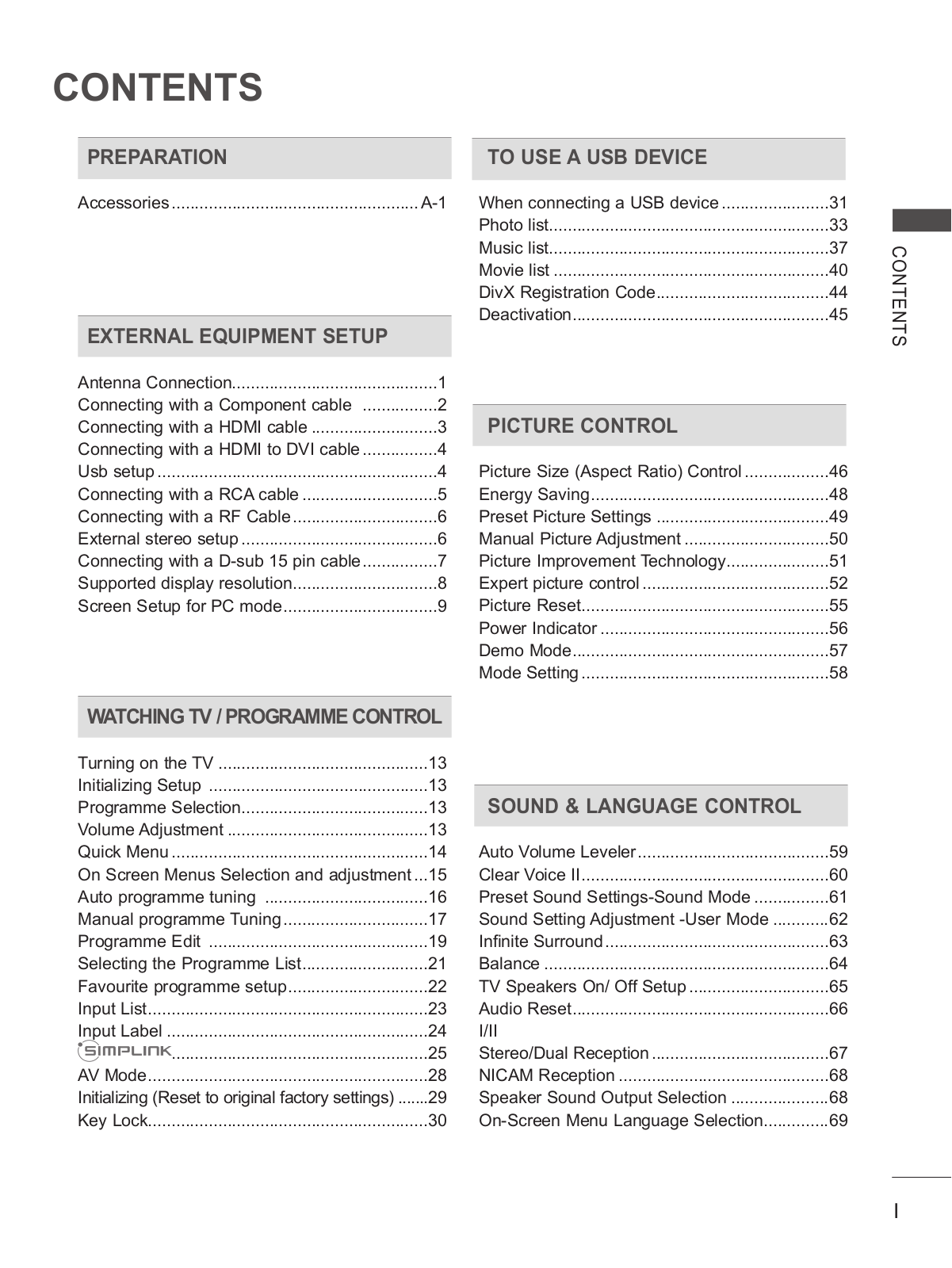
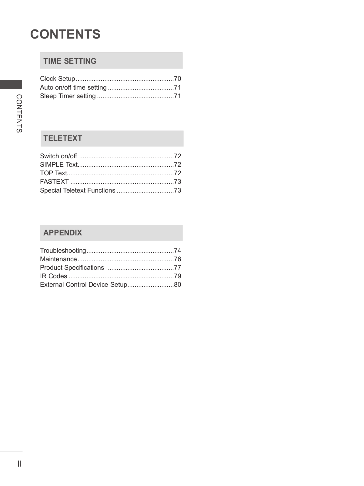
Table of contents
Loading...
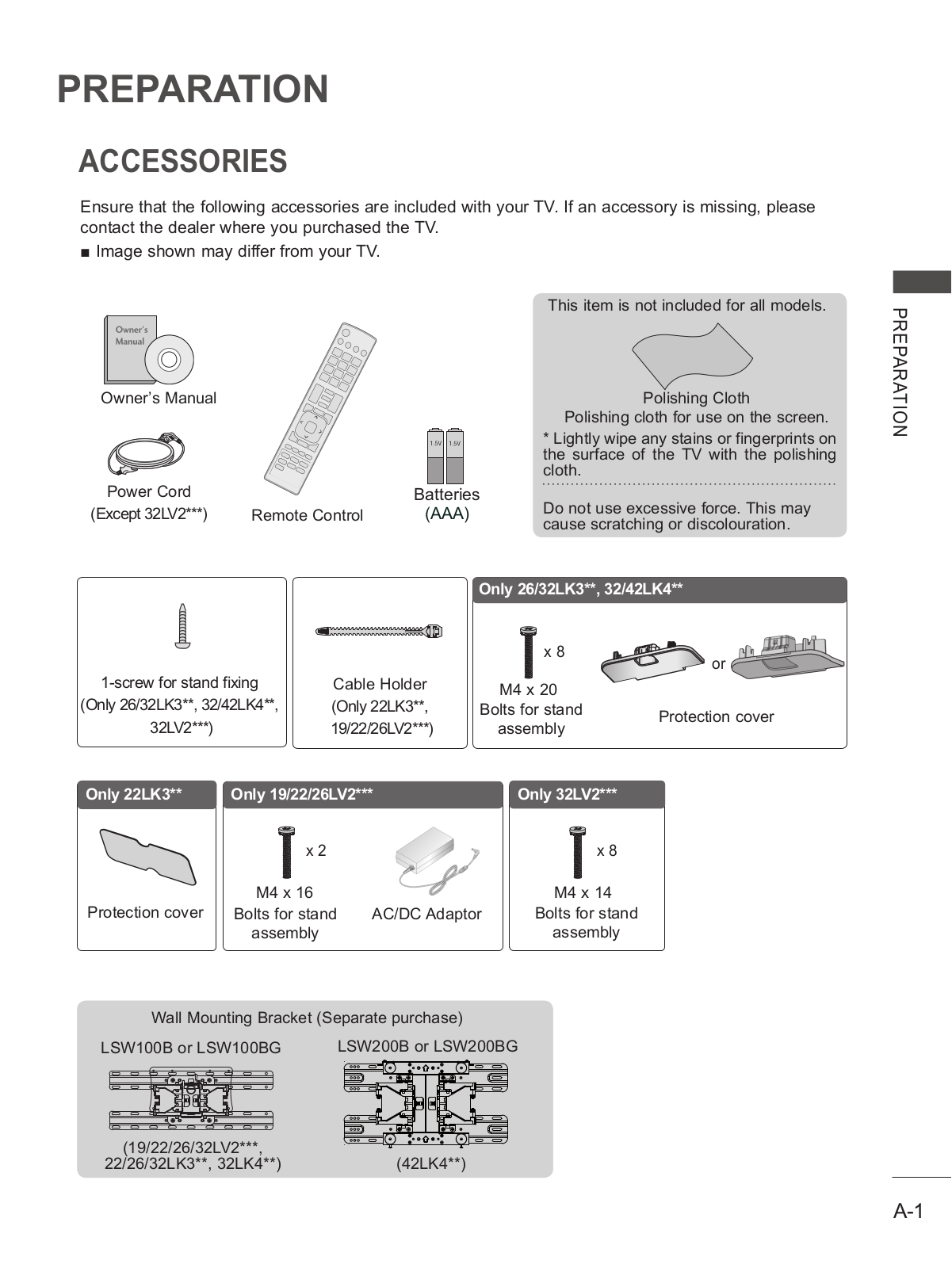
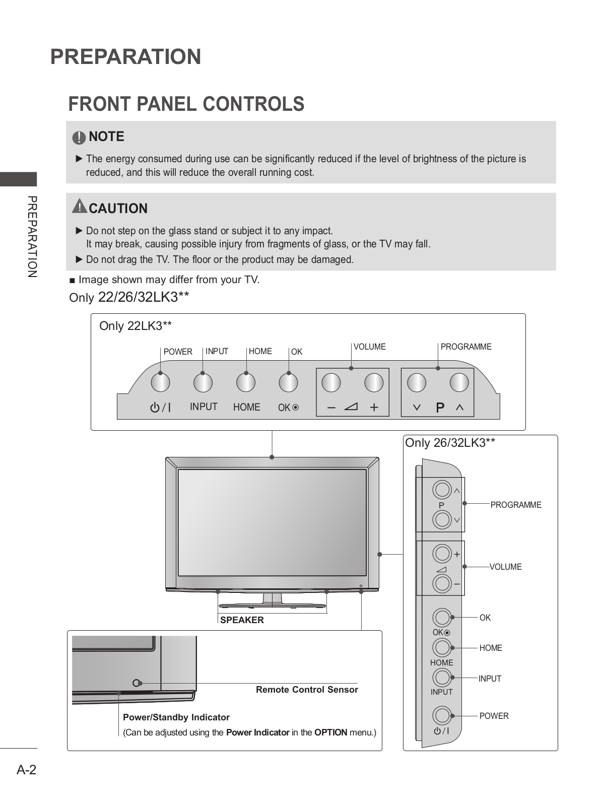
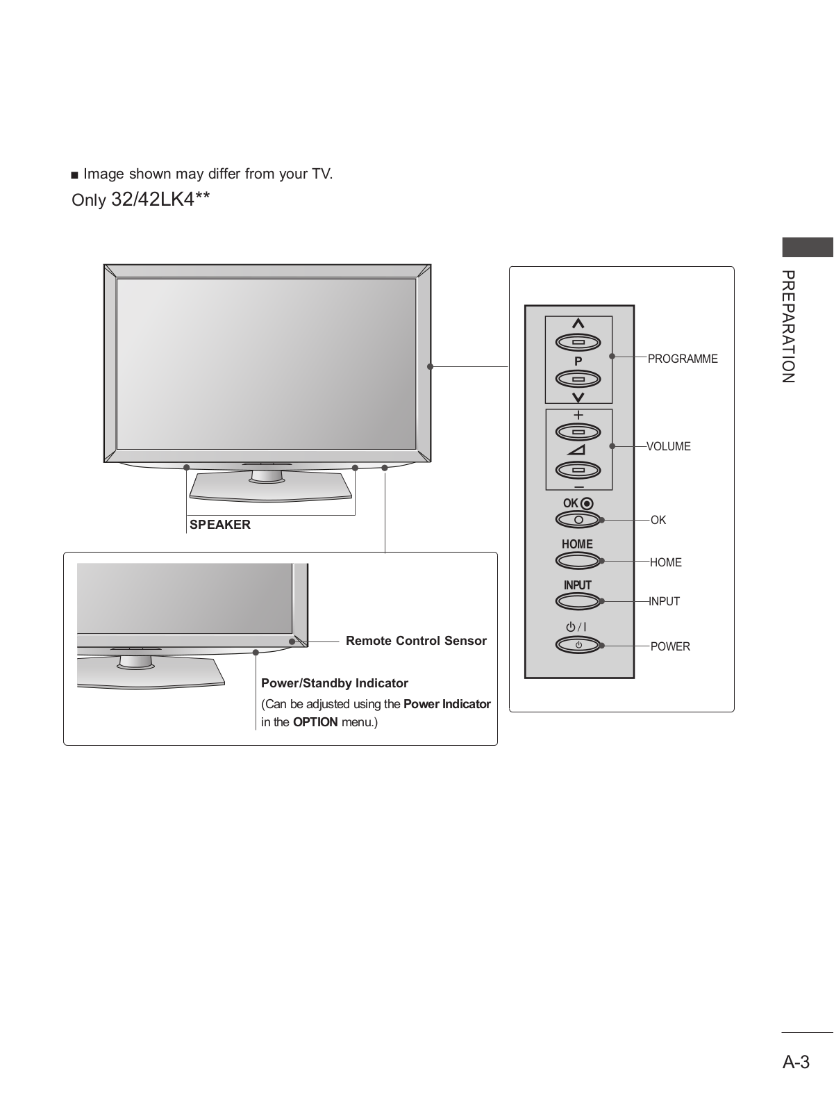
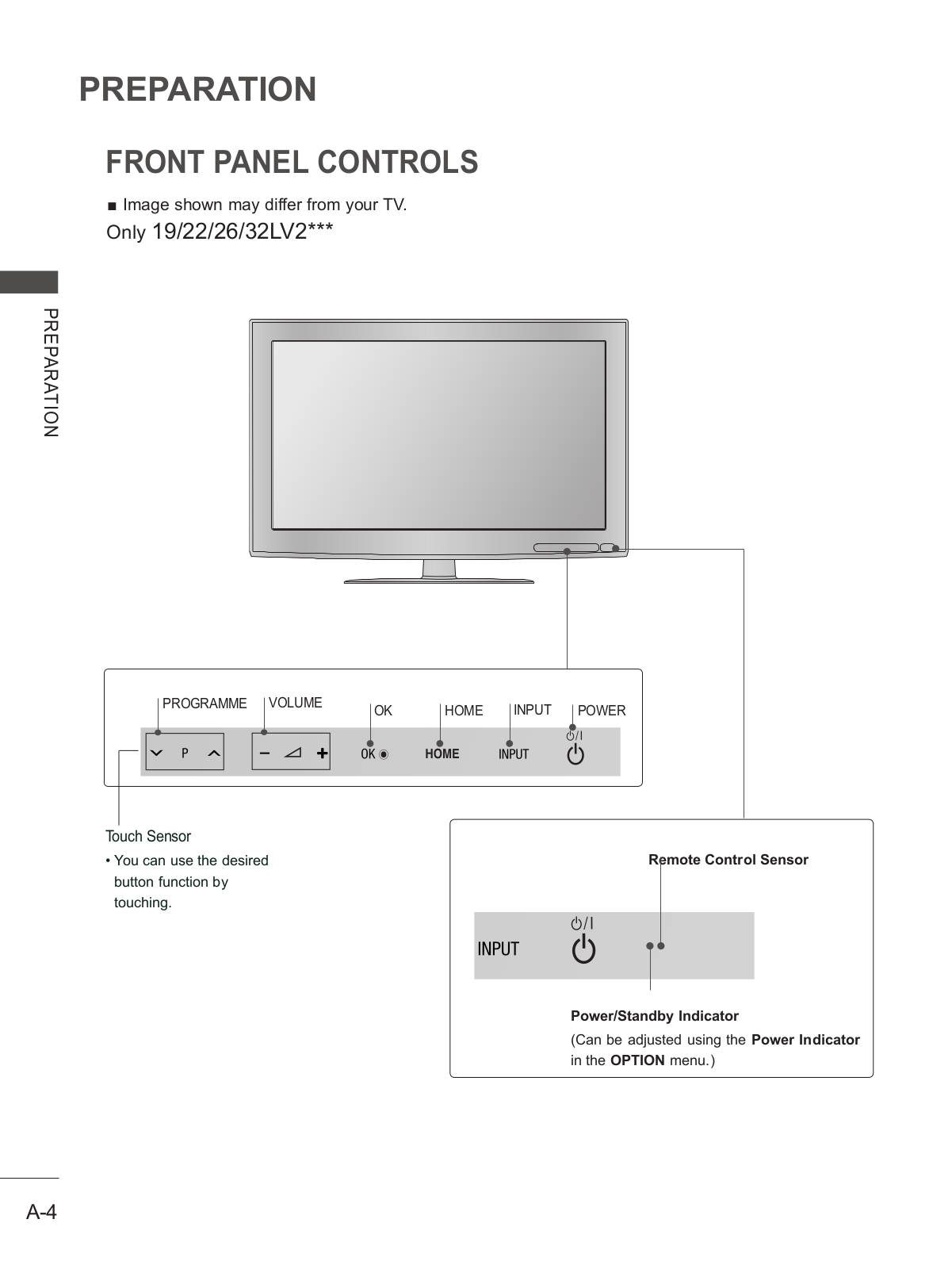
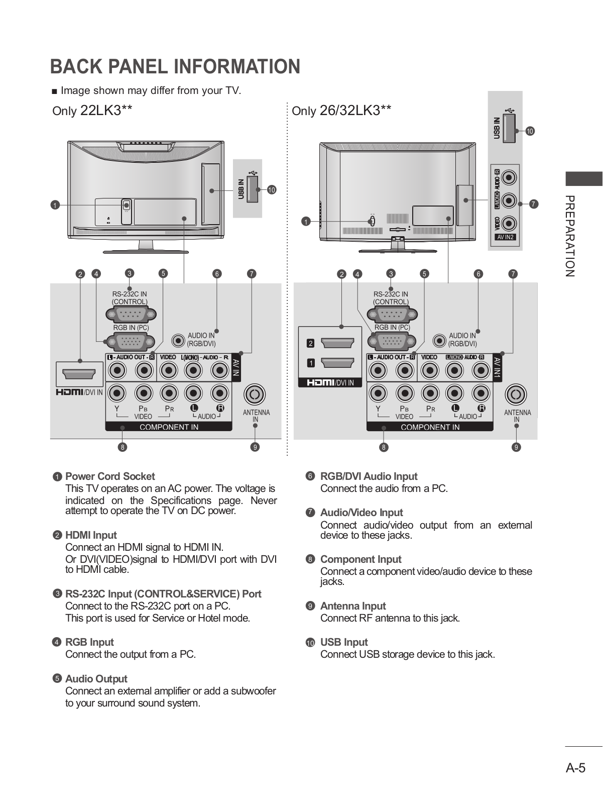
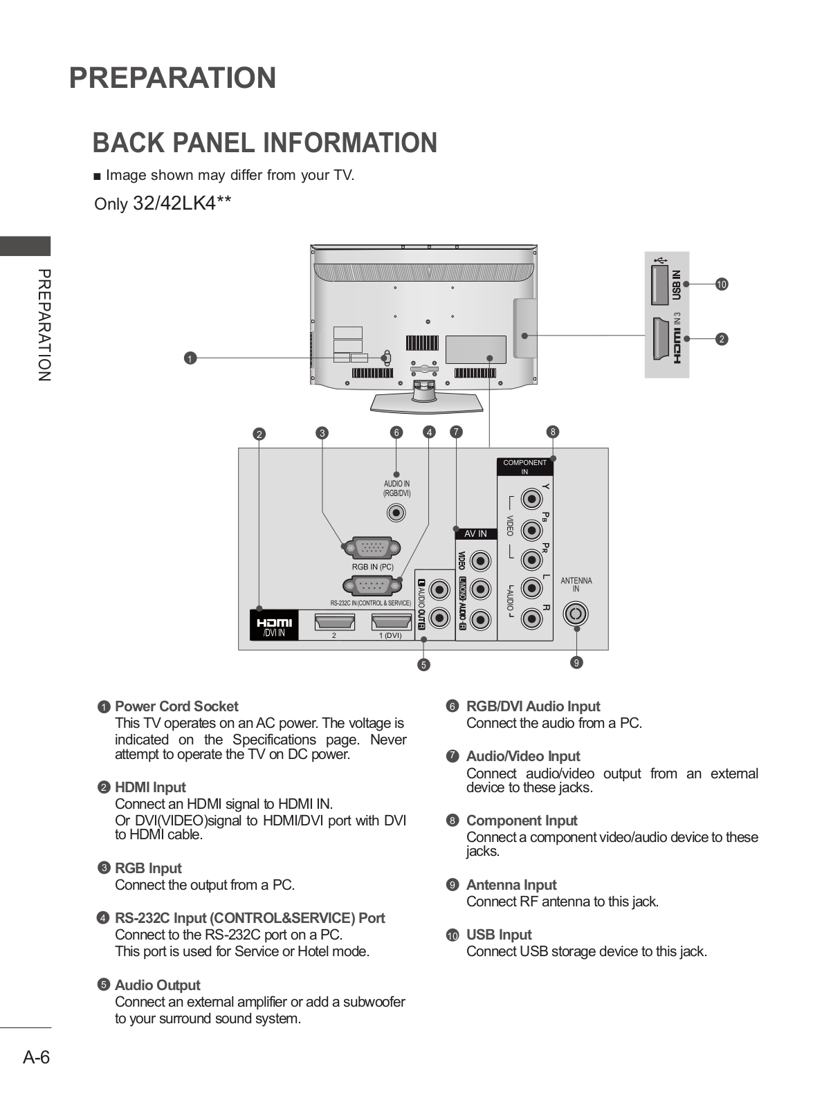
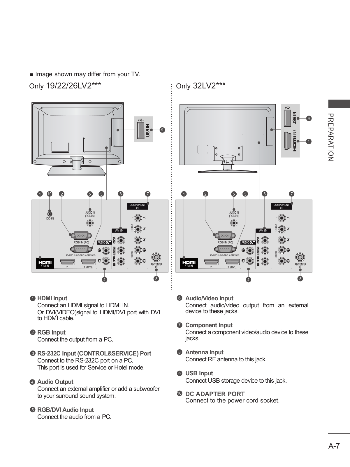
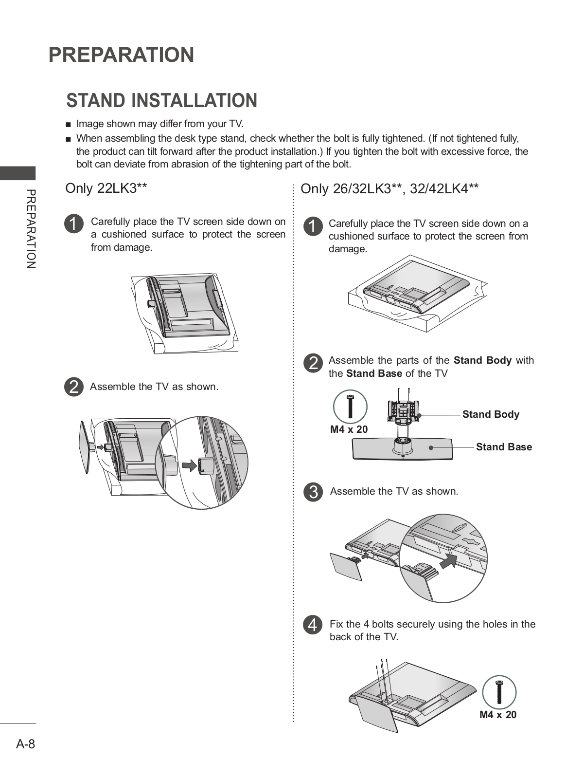
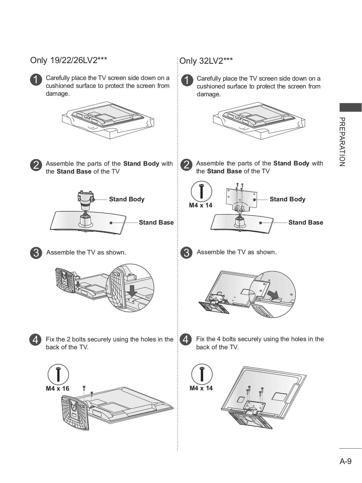
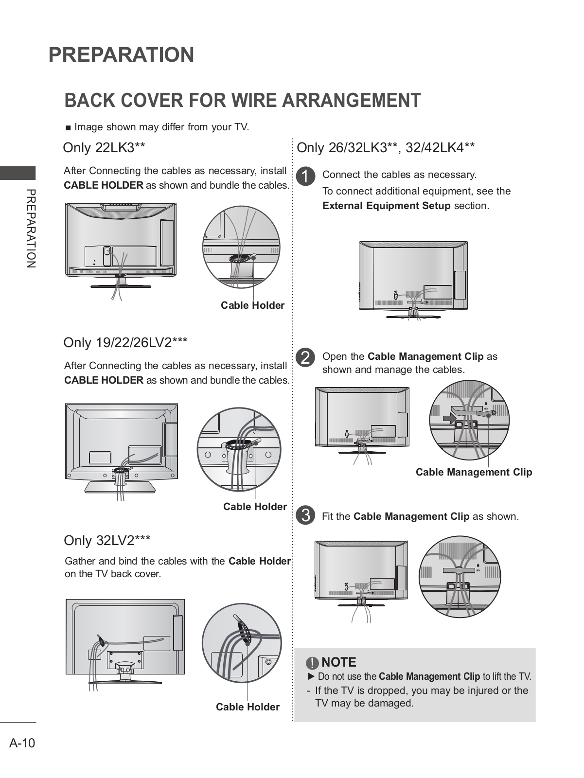
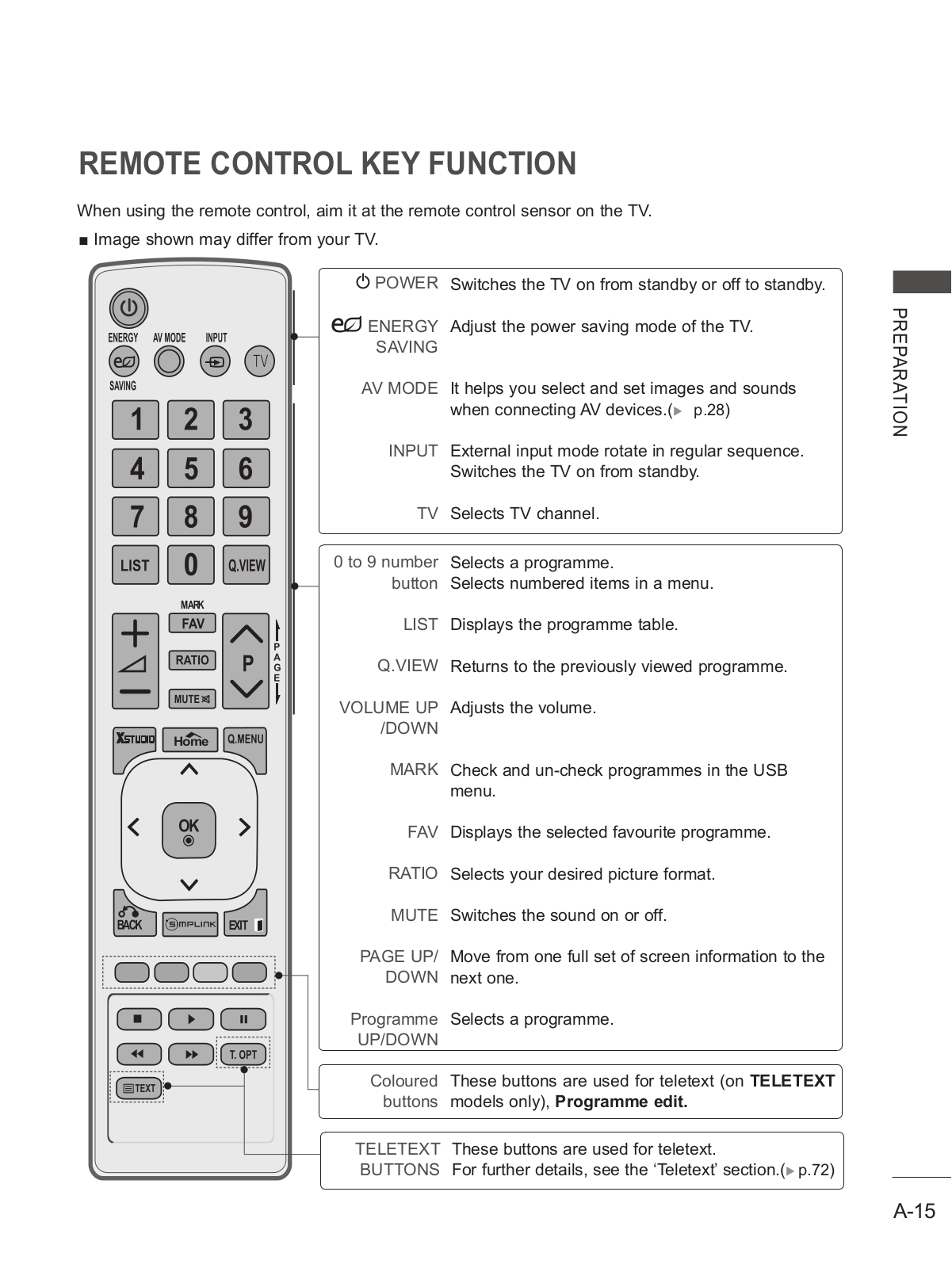
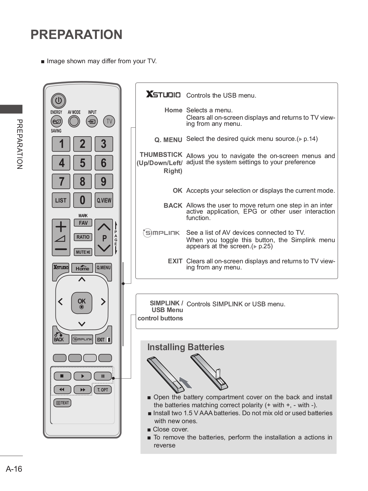
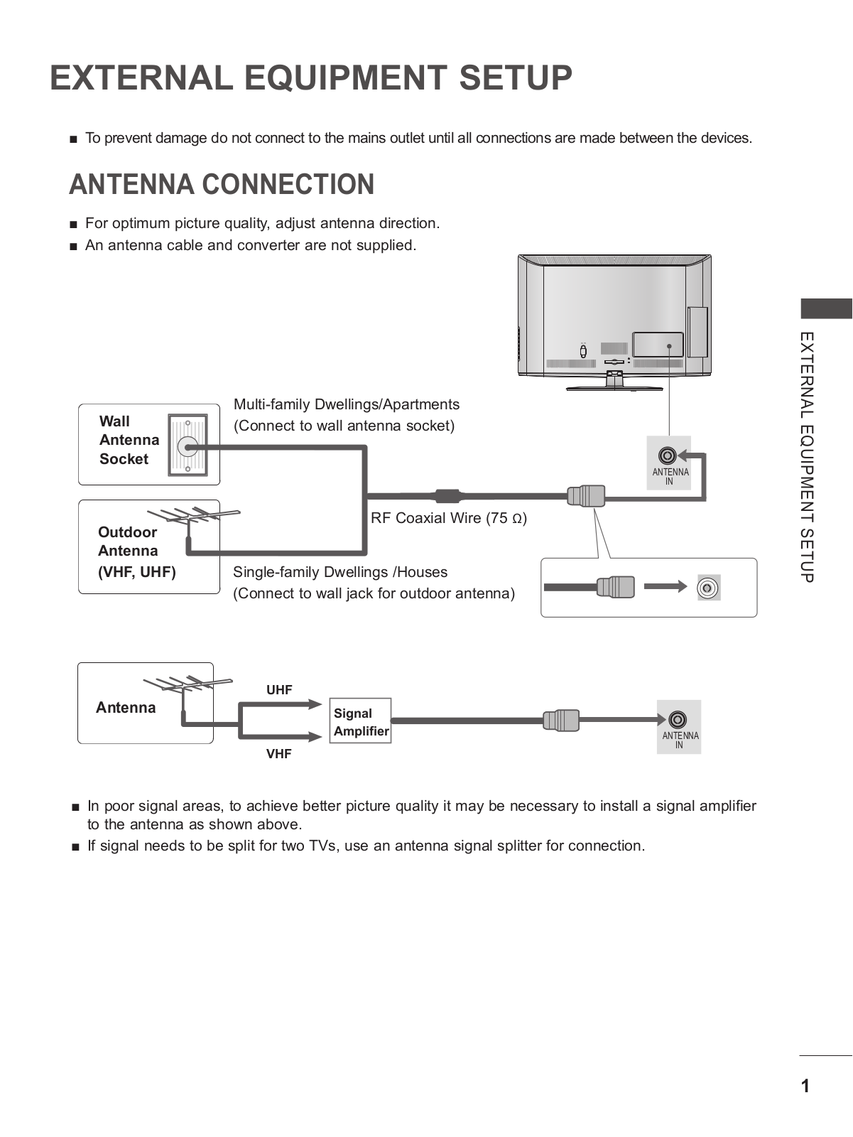
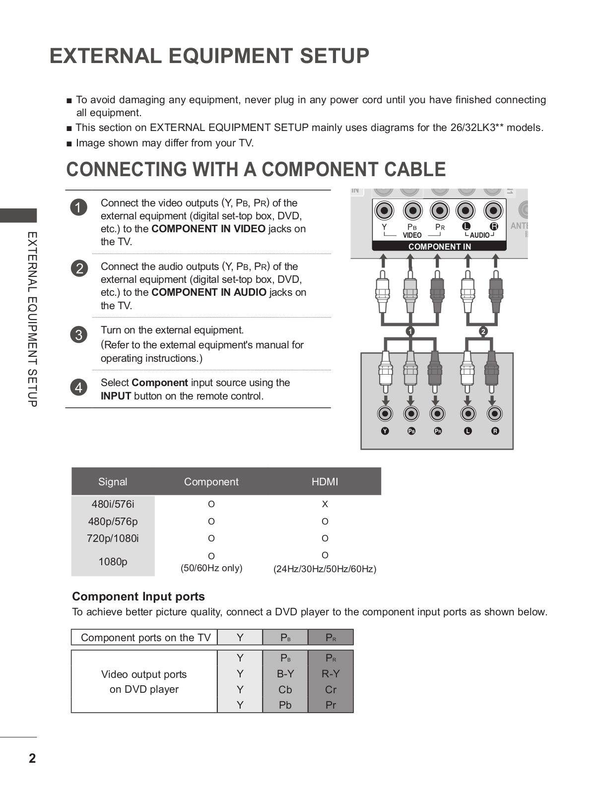
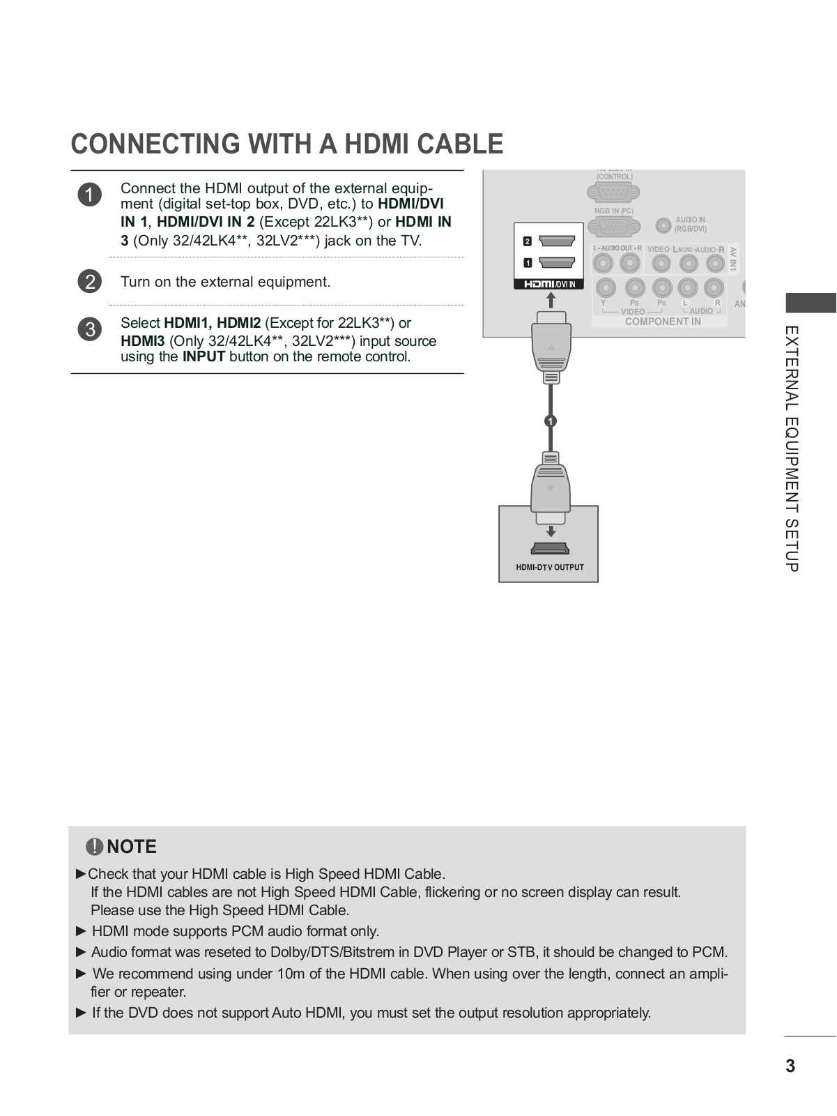
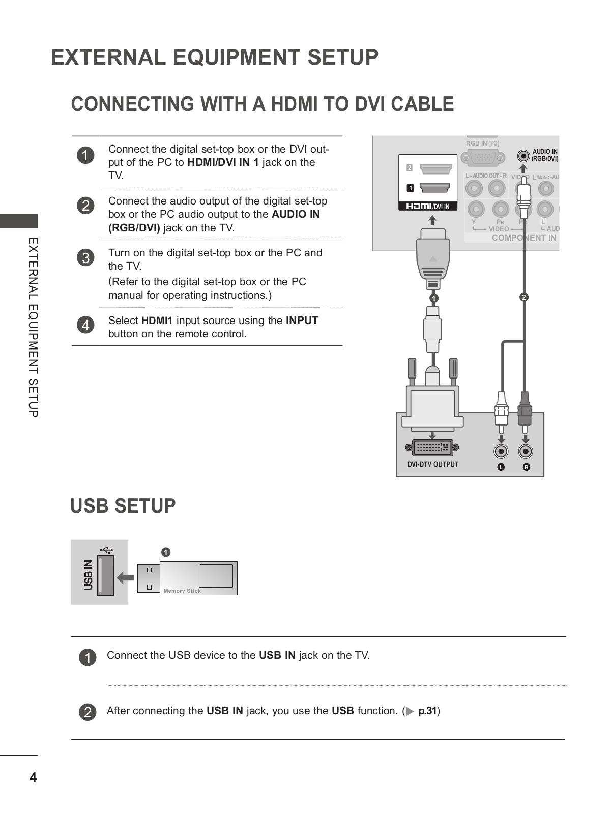
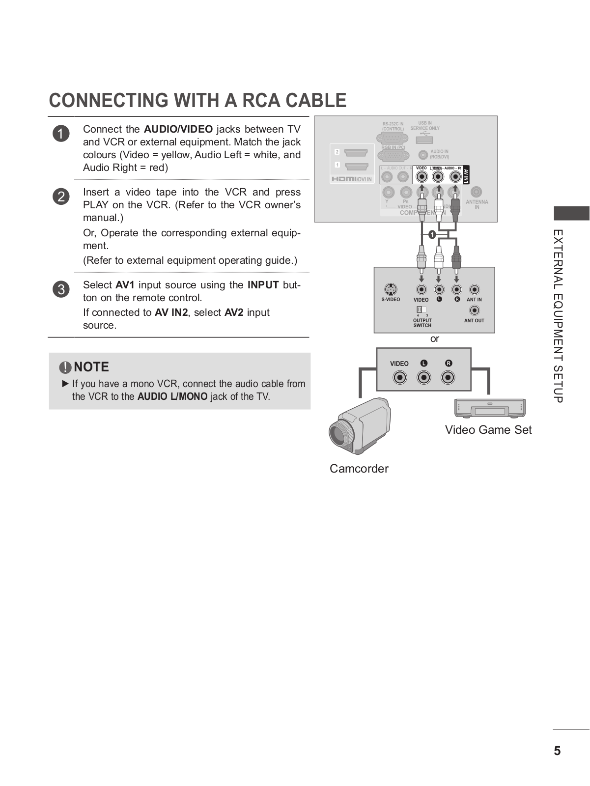
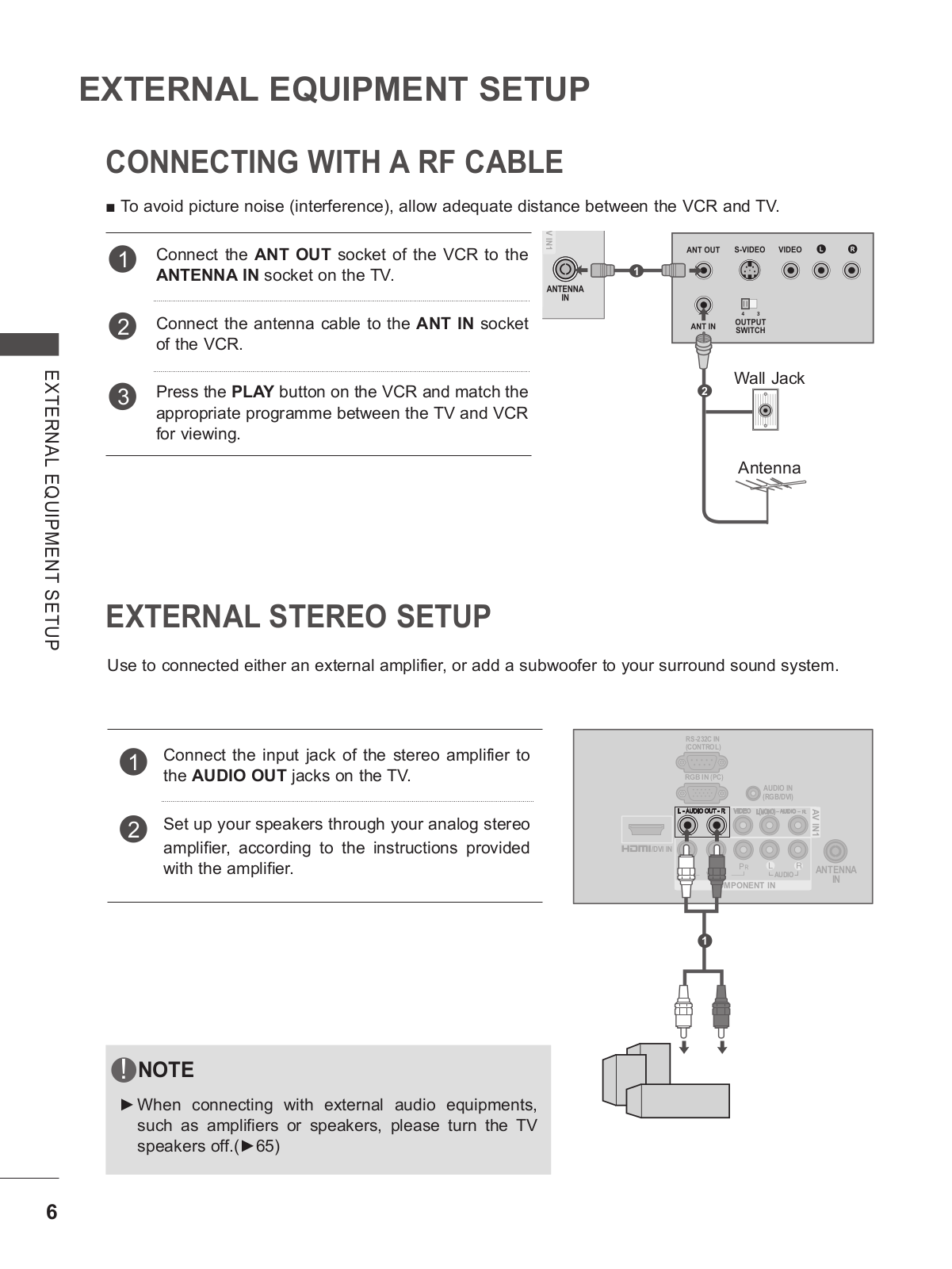
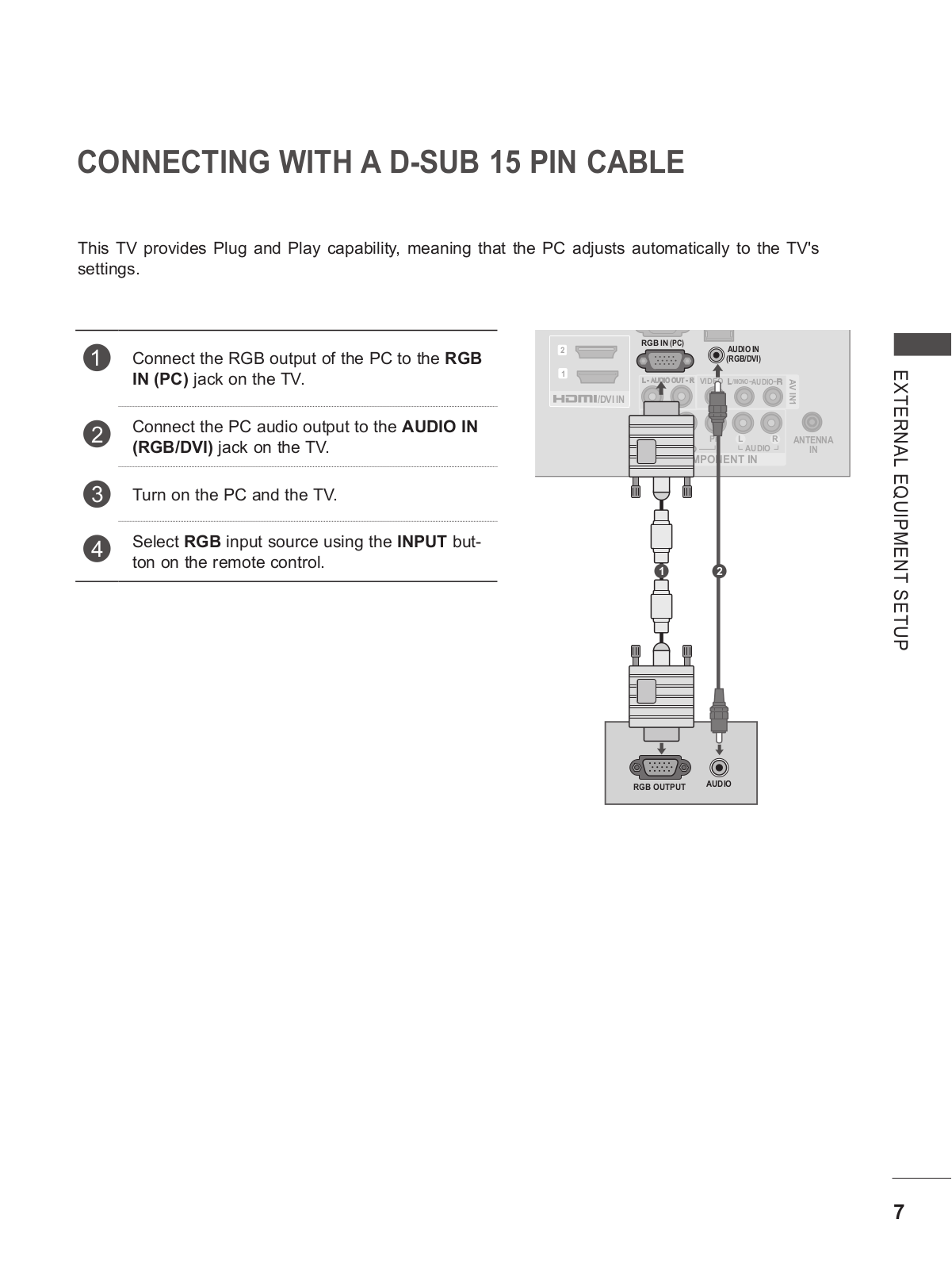
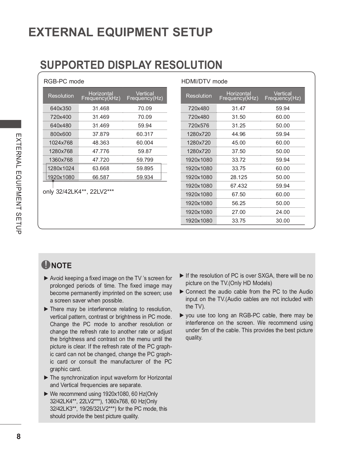
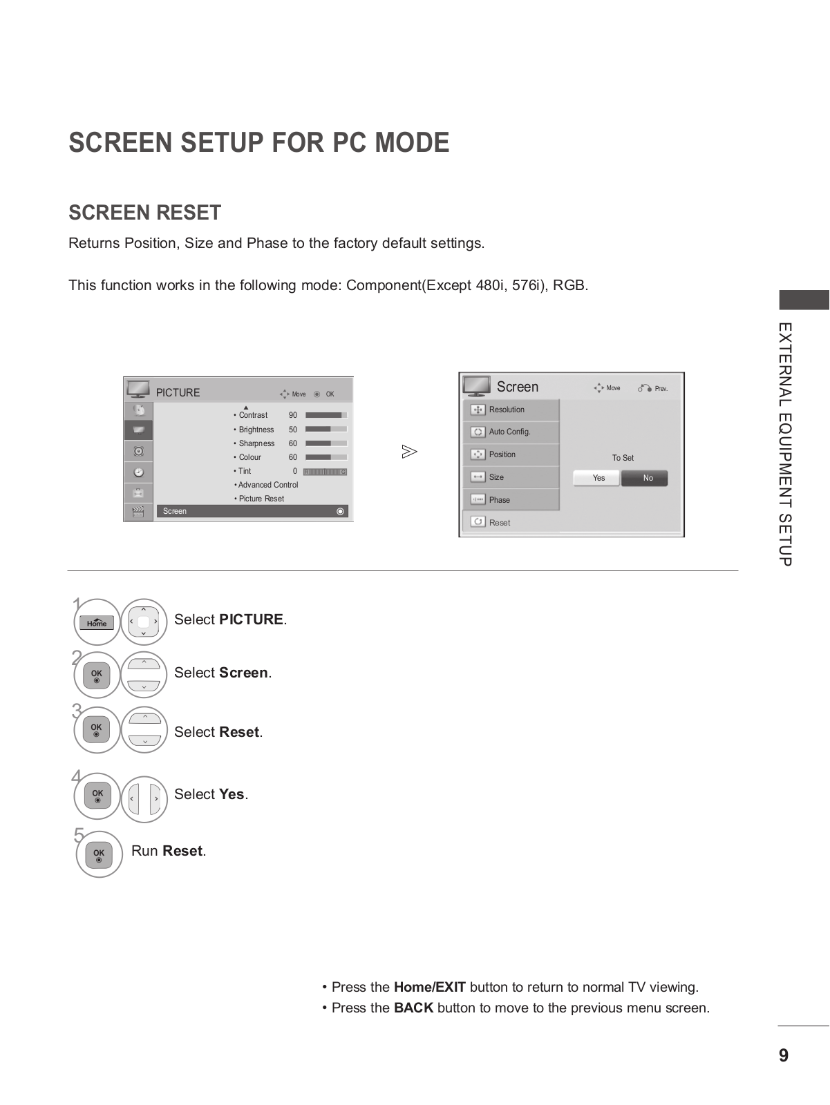
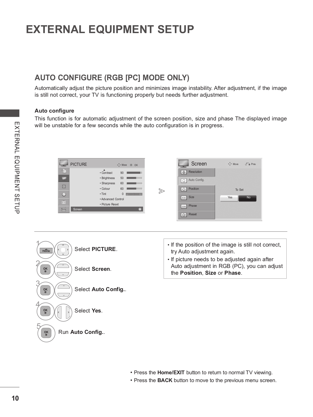
LG 26LK310Y User guide
...
LG User guide
Download
Specifications and Main Features
Frequently Asked Questions
User Manual
Download
Loading...
+
76
hidden pages
Unhide
You need points to download manuals.
1 point = 1 manual.
You can buy points or you can get point for every manual you upload.
Buy points
Upload your manuals
 Loading...