

LG 26LH1DC3 - - 26"" LCD TV, 26LH1DC4, 26LH1DC5 Installation And Operating Manual
Installation and
Operating Guide
26LH1 DC3
26LH1 DC4
26LH1 DCS
Please read this manual carefully before operating
your set.
Retain it for future reference.
Record model number and serial number of the set.
See the label attached on the back cover and quote
this information to your dealer when you require
service.
WARNING TmON
This reminder is provided to call the CATV system installer's
attention to Article 820-40 of the National Electric Code
(U.S.A.). The code provides guidelines for proper
grounding and, in particular, specifies that the cable ground
shall be connected to the grounding system of the building,
as close to the point of the cable entry as practical.
2
IT IS FORBIDDEN TO CONNECT THIS TV
TO ANY TELECOMMUNICATION
NETWORK / TELEPHONE.
This equipment has been tested and found to comply
with the limits for a Class B digital device, pursuant to
Part 15 of the FCC Rules.
These limits are designed to provide reasonable
protection against harmful interference when the
equipment is operated in a residential installation. This
equipment generates, uses and can radiate radio
frequency energy and, if not installed and used in
accordance with the instruction manual, may cause
harmful interference to radio communications. However,
there is no guarantee that interference will not occur in a
particular installation. If this equipment does cause
harmful interference to radio or television reception,
which can be determined by turning the equipment off
and on, the user is encouraged to try to correct the
interference by one or more of the following measures:
, Reorient or relocate the receiving antenna.
, Increase the separation between the equipment and
receiver.
o Connect the equipment into an outlet on a circuit
different from that to which the receiver is
connected.
o Consult the dealer or an experienced radio/TV
technician for help.
Changes or modifications not expressly approved by the
party responsible for compliance could void the user's
authority to operate the equipment.
THE PARTY RESPONSIBLE FOR PRODUCT
COMPLIANCE
(LG Electronics U.S.A., Inc.,)
(2000 Millbrook Drive)
(TELEPHONE NO:I-847-941 -8000)
Donotattempttomodifythisproductinanyway
withoutwrittenauthorizationfromLGElectronics
Corporation.
Unauthorizedmodificationcouldvoidtheuser's
authoritytooperatethisproduct.
Apparatusshallnotbeexposedto drippingor
splashingandnoobjectsfilledwithliquids,suchas
vases,shallnotbeplacedontheapparatus.
THESESERVICINGINSTRUCTIONSAREFORUSEBY
QUALIFIEDSERVICEPERSONNELONLY.TOREDUCE
THERISKOFELECTRICSHOCK,DONOTPERFORM
ANYSERVICINGOTHERTHANTHATCONTAINED
INTHEOPERATINGINSTRUCTIONSUNLESSYOU
AREQUALIFIEDTODOSO.
WhenusedoutsideoftheU.S.,it maybeusedHAR
cordwithfittingofanapprovedagencyisemployed.
(Whenusedoutsideof U.S.,otherpowersupplycords
maybeusedifthecordisapprovedbythelocal
regulatingagency.)
Cleantheexteriorofthistelevisionbyremovingdust
withalint-freecloth.
CAUTION:Toavoiddamagetothesurfaceof the
television,donotuseabrasiveorchemicalcleaning
agents.
YOURPRODUCTHASBEENMANUFACTUREDANDTESTEDWITHYOURSAFETYINMIND.HOWEVER,
IMPROPERUSECANRESULTINPOTENTIALELECTRICALSHOCKORFIREHAZARDS.TOAVOIDDEFEATING
THESAFEGUARDSTHATHAVEBEENBUILTINTOYOURNEWPRODUCT,PLEASEREADANDOBSERVETHE
FOLLOWINGSAFETYPOINTSWHENINSTALLINGANDUSINGYOURNEWPRODUCT,ANDSAVETHEMFOR
FUTUREREFERENCE.OBSERVINGTHESIMPLEPRECAUTIONSDISCUSSEDINTHISMANUALCANHELPYOU
GETMANYYEARSOFENJOYMENTANDSAFEOPERATIONTHATAREBUILTINTOYOURNEWPRODUCT.
3
SAFETY [NST S
IMPORTANT SAFETYINSTRUCTIONS
1. Read these instructions.
2. Keep these instructions.
3. Heed all warnings.
4. Follow all instructions.
5. Do not use this apparatus near water.
6. Clean only with dry cloth.
Z Do not block any ventilation openings. Install in accordance with the manufacturer's instructions.
8. Do not install near any heat sources such as radiators, heat registers, stoves, or other apparatus (including
amplifiers) that produce heat.
9. Do not defeat the safety purpose of the polarized or grounding-type plug. A polarized plug has two blades with
one wider than the other. A grounding type plug has two blades and a third grounding prong. The wide blade or
the third prong is provided for your safety. If the provided plug does not fit into your outlet, consult an
electrician for replacement of the obsolete outlet.
10. Protect the power cord from being walked on or pinched particularly at plugs, convenience receptacles, and the
point where they exit from the apparatus.
11. Only use attachments/accessories specified by the manufacturer.
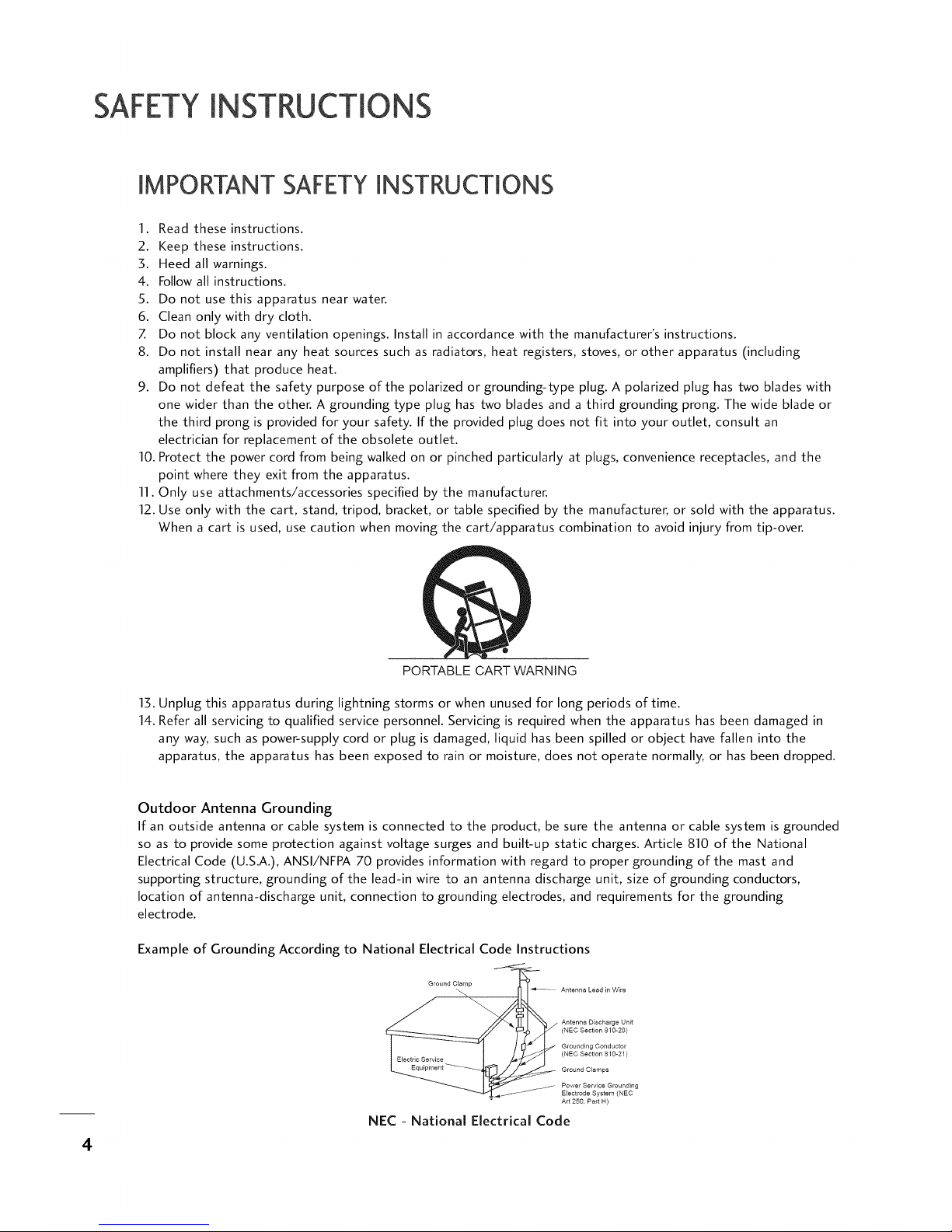
12. Use only with the cart, stand, tripod, bracket, or table specified by the manufacturer, or sold with the apparatus.
When a cart is used, use caution when moving the cart/apparatus combination to avoid injury from tip-over.
PORTABLE CART WARNING
13. Unplug this apparatus during lightning storms or when unused for long periods of time.
14. Refer all servicing to qualified service personnel. Servicing is required when the apparatus has been damaged in
any way, such as power-supply cord or plug is damaged, liquid has been spilled or object have fallen into the
apparatus, the apparatus has been exposed to rain or moisture, does not operate normally, or has been dropped.
4
Outdoor Antenna Grounding
If an outside antenna or cable system is connected to the product, be sure the antenna or cable system is grounded
so as to provide some protection against voltage surges and built-up static charges. Article 810 of the National
Electrical Code (U.S.A.), ANSI/NFPA 70 provides information with regard to proper grounding of the mast and
supporting structure, grounding of the lead-in wire to an antenna discharge unit, size of grounding conductors,
location of antenna-discharge unit, connection to grounding electrodes, and requirements for the grounding
electrode.
Example of Grounding According to National Electrical Code Instructions
Ground Clamp __
Antenna Lead in Wire
Antenna Discharge Unit
(NEC Section 810-20)
Grounding Conductor
(NEC Section 810-21)
Ground Clamps
Power Service Grounding
- _I _I_ _- Electrode System (NEC
Art 250. Part H)
NEC - National Electrical Code
CONTENTS
WARNING / CAUTION ........................... 2
SAFETY INSTRUCTIONS ........................ 4
CONTENTS ............................................ S
Accessories ................................................. 6
Set Password & Lock System ........................... 3S
Movie & TV Ratings ...................................... 37
Front Panel Information ............................... 7
Back Panel Information ................................ 8
VESA Wall Mounting .................................... 9
Antenna or Cable Connection ...................... 10
HD Receiver Setup ...................................... 11
DVD Setup ............................................... 14
VCR Setup ................................................ 16
Other A/V Source Setup .............................. 18
Digital Audio Output ................................. 18
PC Setup ................................................. 19
Screen Setup for PC mode .......................... 21
DVI Hookup To RiP or DVD Player ............... 22
Computer PC Hookup ............................... 22
User Remote Control Button Functions ......... 23
Caption / Text .......................................... 41
Preset Sound Settings .......................... 43
Sound Setting Adjustment-user Mode ..... 43
Sound Balance Setup ........................... 44
Digital Audio Output Settings ............. 44
Aautomatic Volume Control Settings .... 4S
Analog Audio Settings ......................... 4S
Digital Audio Language Settings ............ 46
Using External Speakers ...................... 46
Menu Language .................................. 47
Menu Transparency Settings .................. 48
Set ID .............................................. 48
Preset Picture Settings .............................. 49
Screen Format Adjustments ................. SO
Noise Reduction ................................. $1
Film Mode Options ............................ $1
Installer Remote Control Button Functions .... 24
On-Screen Menus Selection .......................... 2S
Channel Search .......................................... 26
Clock Setting ............................................ 30
Daylight Saving ................................... 32
Time Zone Settings .............................. 32
TV Activation Time Settings ................... 33
TV Deactivation Time Settings ............... 33
Auto Off ........................................... 34
Installer Overview ....................................... $2
Commercial Mode Setup ............................. $3
Cloning Connections/Learning Setup ............. $4
Clone Programmer/Learning Setup ............... SS
Cloning Connections/Teaching Setup ............. $6
Installer Menu ........................................... $8
Peference .................................................. 63
Troubleshooting ........................................ 69
Cloning Procedure Troubleshooting ............... 71
Clone Troubleshooting Flow Chart ................ 73
TV Operating Check .................................. 74
Glossary of Terms ...................................... 7S
Installer Quick Setup Guide ......................... 76
5
ACCESSORIES
"D
m
©
z
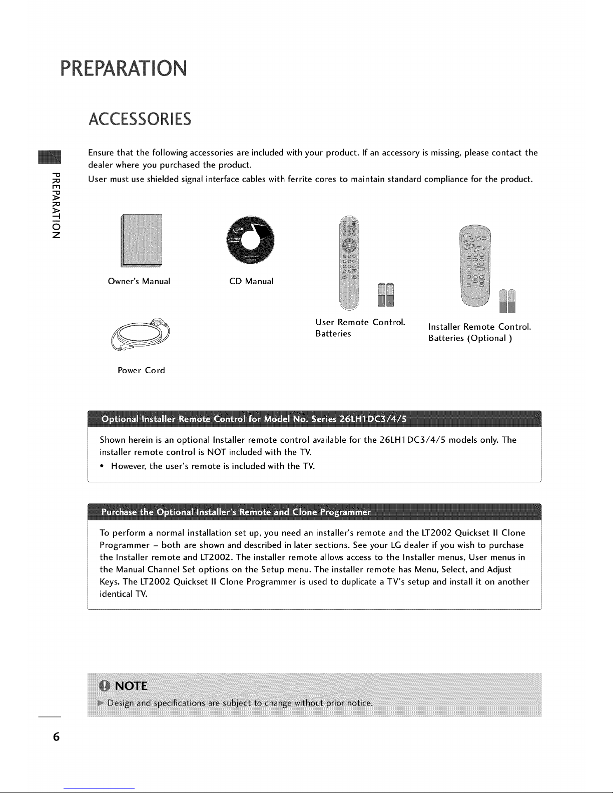
Ensure that the following accessories are included with your product. If an accessory is missing, please contact the
dealer where you purchased the product.
User must use shielded signal interface cables with ferrite cores to maintain standard compliance for the product.
Owner's Manual CD Manual
Power Cord
User Remote Control.
Batteries
Installer Remote Control.
Batteries (Optional)
Shown herein is an optional Installer remote control available for the 26LH1 DC3/4/5 models only. The
installer remote control is NOT included with the TV.
• However, the user's remote is included with the TV.
To perform a normal installation set up, you need an installer's remote and the LT2002 Quickset II Clone
Programmer - both are shown and described in later sections. See your LG dealer if you wish to purchase
the Installer remote and LT2002. The installer remote allows access to the Installer menus, User menus in
the Manual Channel Set options on the Setup menu. The installer remote has Menu, Select, and Adjust
Keys. The LT2002 Quickset II Clone Programmer is used to duplicate a TV's setup and install it on another
identical TV.
6
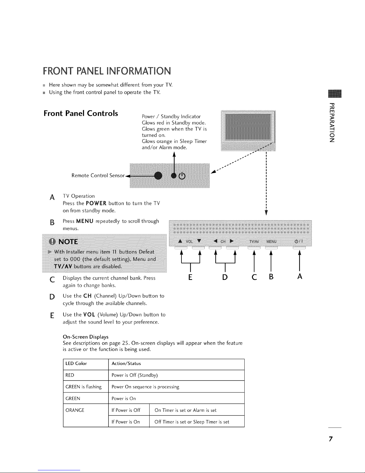
FRONT PANELINFORMATION
_ Here shown may be somewhat different from your TV.
Using the front control panel to operate the TV.
Front Panel Controls
Power / Standby Indicator
Glows red in Standby mode.
Glows green when the TV is
turned on.
Glows orange in Sleep Timer
and/or Alarm mode.
Remote Control
_1_ _
rT1
0
z
A TV Operation
Press the POWER button to turn the TV
on from standby mode.
B Press MENU repeatedly to scroll through
menus.
V
C
D
E
Displays the current channel bank. Press
again to change banks.
Use the CH (Channel) Up/Down button to
cycle through the available channels.
Use the VO/ (Volume) Up/Down button to
adjust the sound level to your preference.
LiJ LlJ
D
C
On-Screen Displays
See descriptions on page 25. On-screen displays will appear when the feature
is active or the function is being used.
LED Color
RED
GREEN is flashing
GREEN
ORANGE
Action/Status
Power is Off (Standby)
Power On sequence is processing
Power is On
If Power is Off On Timer is set or Alarm is set
If Power is On Off Timer is set or Sleep Timer is set
7
PREPARATION
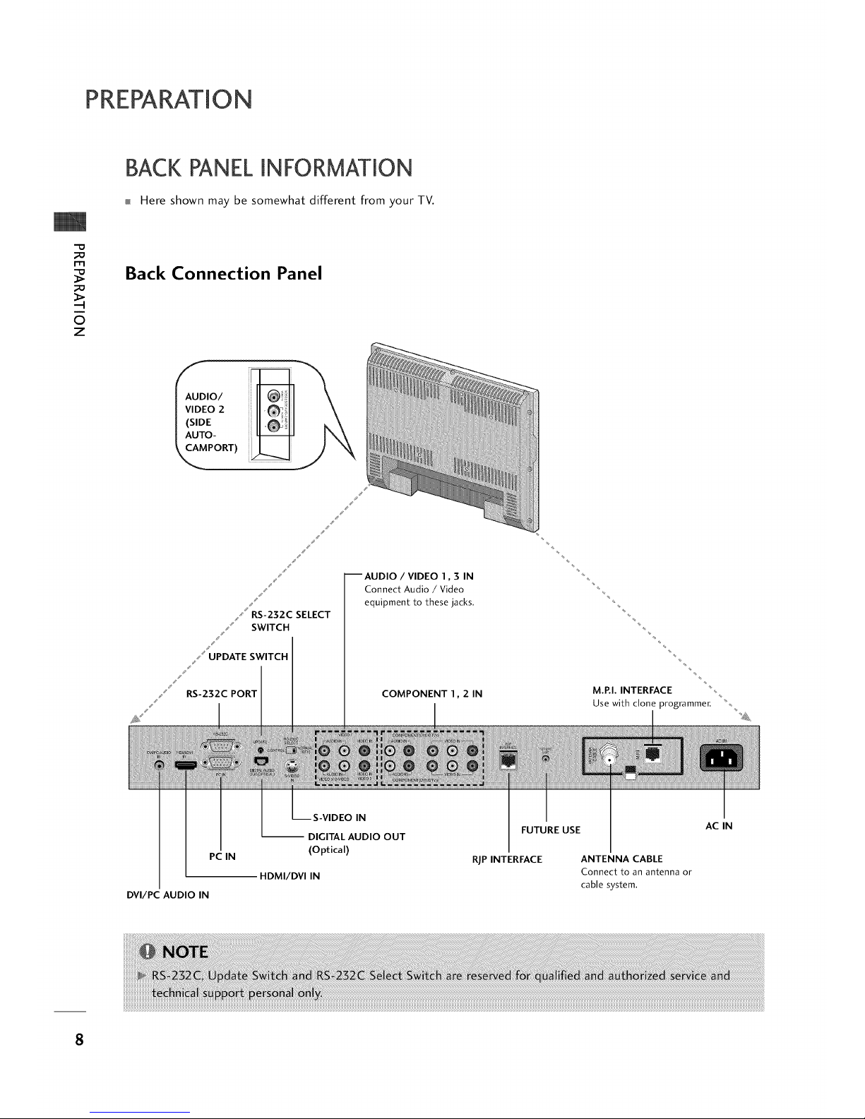
BACK PANELINFORMATION
Here shown may be somewhat different from your TV.
m
©
z
Back Connection Panel
j,'
--AUDIO / VIDEO 1,3 IN
Connect Audio / Video
equipment to these jacks.
COMPONENT 1,2 IN
M.P.I. INTERFACE
Use with clone programmer.
iiiiiiiiiiiiiliii!i!iiiii!!!!!
PC IN
DVI/PC AUDIO IN
IN
-- DIGITAL AUDIO OUT
(Optical)
HDMI/DVI IN
FUTURE USE
RIP INTERFACE ANTENNA CABLE
Connect to an antenna or
cable system.
AC IN
8

VESAWALLMAUNTING
Here shown may be somewhat different from your TV.
There are several Vesa standard
mounts available that can be used
with this TV. The mount shown to the
right would be installed on the TV
back using required bolts in the four
pre-threaded holes provided.
Follow any instructions supplied with
the Vesa mount if one is to be used
for the TV installation.
Vesa Standard
Mounting Holes
-D
m
0
z
TV Swivel Stand
Swivel Stand
- The TV can be conveniently
swiveled on its stand 30 ° to
the left or right to provide
optimum viewing angles.
9
EXTERNALEQUIPMENT SETUP
ANTENNA OR CABLECONNECTION
rT1
x
-4
rT1
z
r--
_D
c
-O
rT1
z
-4
rT1
-4
C
•
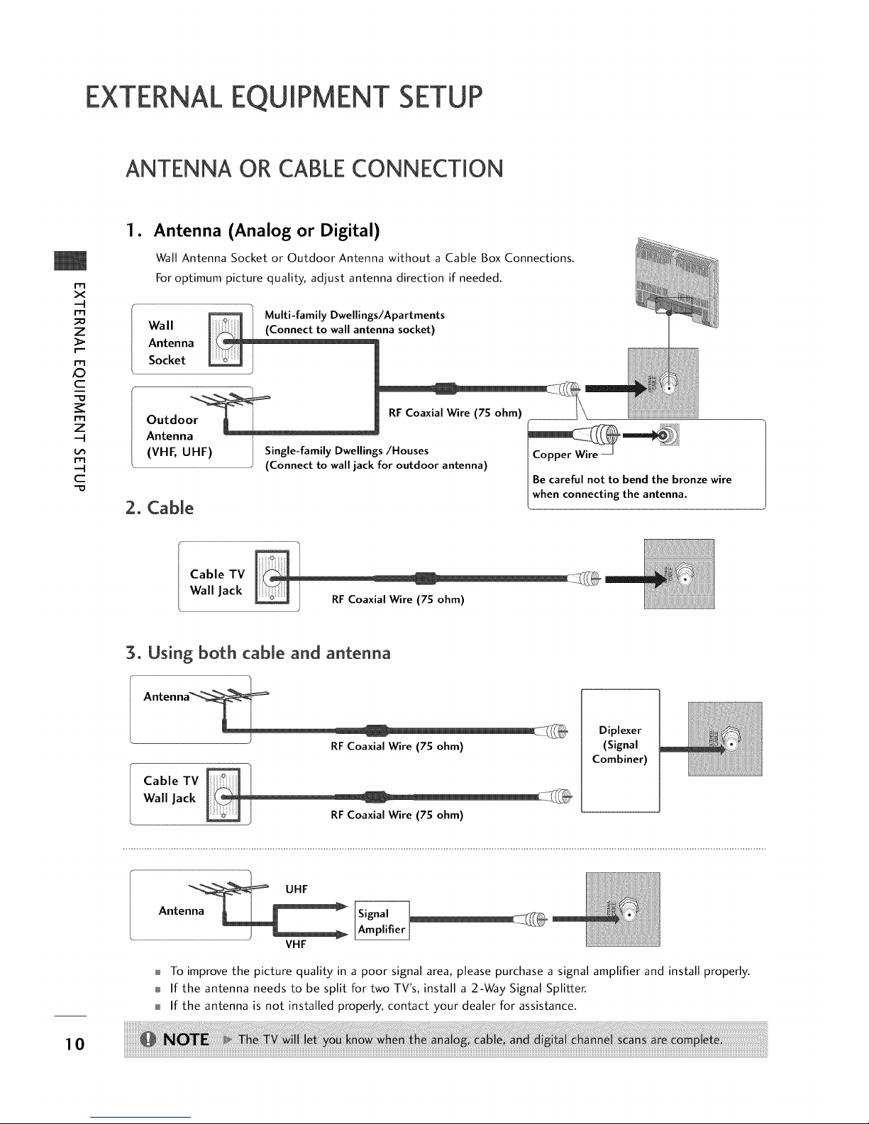
Antenna (Analog or Digital)
Wall Antenna Socket or Outdoor Antenna without a Cable Box Connections.
For optimum picture quality, adjust antenna direction if needed.
Wall
Antenna
Socket
Multi-family Dwellings/Apartments
nna socket)
2. Cable
Be careful not to bend the bronze wire
when connecting the antenna.
Cable TV _ I
Wall Jack
RF Coaxial Wire (7S ohm)
3. Using both cable and antenna
Antenna_
RFCoaxial Wire (7S ohm)
Cable TV _ I
Wall Jack
RFCoaxial Wire (7S ohm)
Diplexer
(Signal
Combiner)
UHF
Antenna _
VHF
To improve the picture quality in a poor signal area, please purchase a signal amplifier and install properly.
If the antenna needs to be split for two TV's, install a 2-Way Signal Splitter.
If the antenna is not installed properly, contact your dealer for assistance.
10
To prevent the equipment damage, never plug in any power cords until you have finished connecting all
equipment.
HD RECEIVERSETUP
This TV can receive Digital Over-the-air/Cable signals without an external digital set-top box. However, if you do
receive digital signals from a digital set-top box or other digital external device, refer to the figure as shown below.
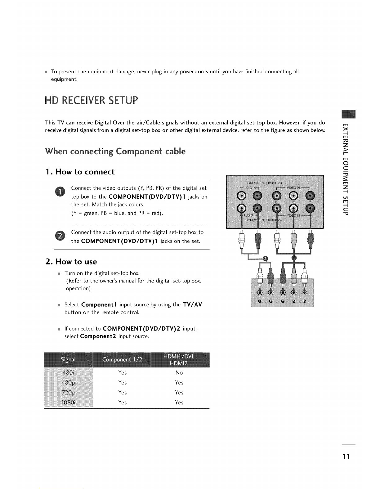
When connecting Component cable
1. How to connect
Connect the video outputs (Y, PB, PR) of the digital set
top box to the COMPONENT(DVD/DTV)I jacks on
the set. Match the jack colors
(Y = green, PB = blue, and PR = red).
Connect the audio output of the digital set-top box to
the COMPONENT(DVD/DTV)I jacks on the set.
m
x
-q
m
z
m
_D
c
-D
m
z
-q
m
-q
c
-D
2. How to use
Turn on the digital set-top box.
(Refer to the owner's manual for the digital set-top box.
operation)
Select Component1 input source by using the TV/AV
button on the remote control.
If connected to COMPONENT(DVD/DTV)2 input,
select Component2 input source.
iiiiiiiiiiiiiiiiiiiiiiiiiiiiiiiiiiiiiiiiiiiiiiiiiiiiiiil¸i!iiiiiiiiiiiiiiiiiiiiiiiiiiiiiiiiiiiiiiiiiiii_!i!_ii!6_i_!i!i!i!i!ii_ii_ii_ii_ii_ii_ii_ii_ii_ii_ii_ii_ii_ii_ii_ii_ii_ii_ii_ii_ii_ii_ii_ii_ii_ii_ii_ii_ii_ii_ii_iii!i!i!ii_i!_i!_ii!i!iiii
..............................ii Uiiiii¸iii ¸i!i!iii!ii!iii!ii
iiiiiiiiiiiiiiiiiiiiiiiiiiiii_ii_iii_i!_!!!!!!_!!!!!!!!!!!!!!!!!!!!!!!!!!!!!!!!!!!!!!!!!!!!!!!!!!!!!!!_i_'''
iiiiiiiiiiiiiiiiiiiiiiiiiiiiiiiiiiiiiiiiiiiii_i!!_!!_!!_!!_!!_!!_!!_!!_!!_!!_!!_!!_!!_!!_!!_!!_!!_!!_!!_!!_!!_!!_!!_!!_!!_!!_!!_!!_!!_!!_!!_!!_!!_!!_!!_!_!_!!,'¸_J¸_
Yes No
Yes Yes
Yes Yes
Yes Yes
11
EXTERNALEQUIPMENT SETUP
m
x
-4
m
_o
z
m
/O
c
-O
m
z
-4
m
-4
C
-O
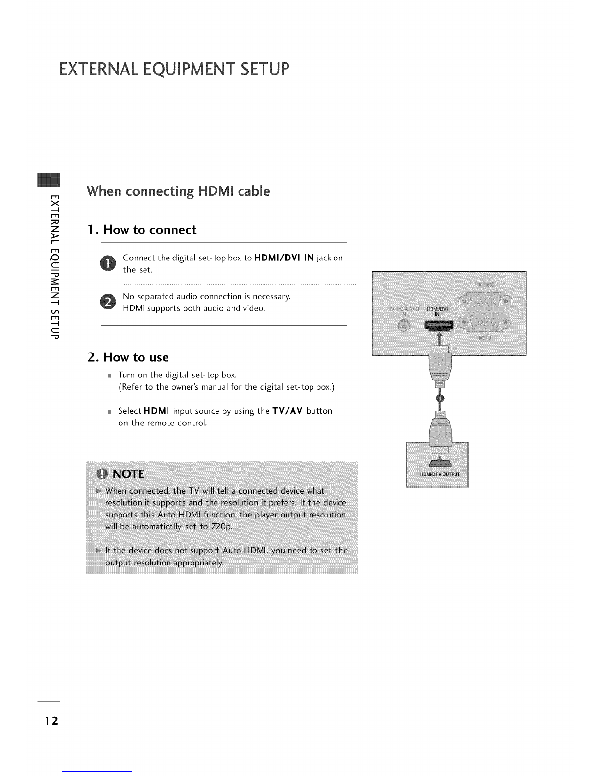
When connecting HDMJ cabJe
1. How to connect
O onnect the digital set-top box to HDMI/DVI IN jack on
the set.
No separated audio connection is necessary.
HDMI supports both audio and video.
2. How to use
Turn on the digital set-top box.
(Refer to the owner's manual for the digital set-top box.)
Select HDMI input source by using the TV/AV button
on the remote control.
12
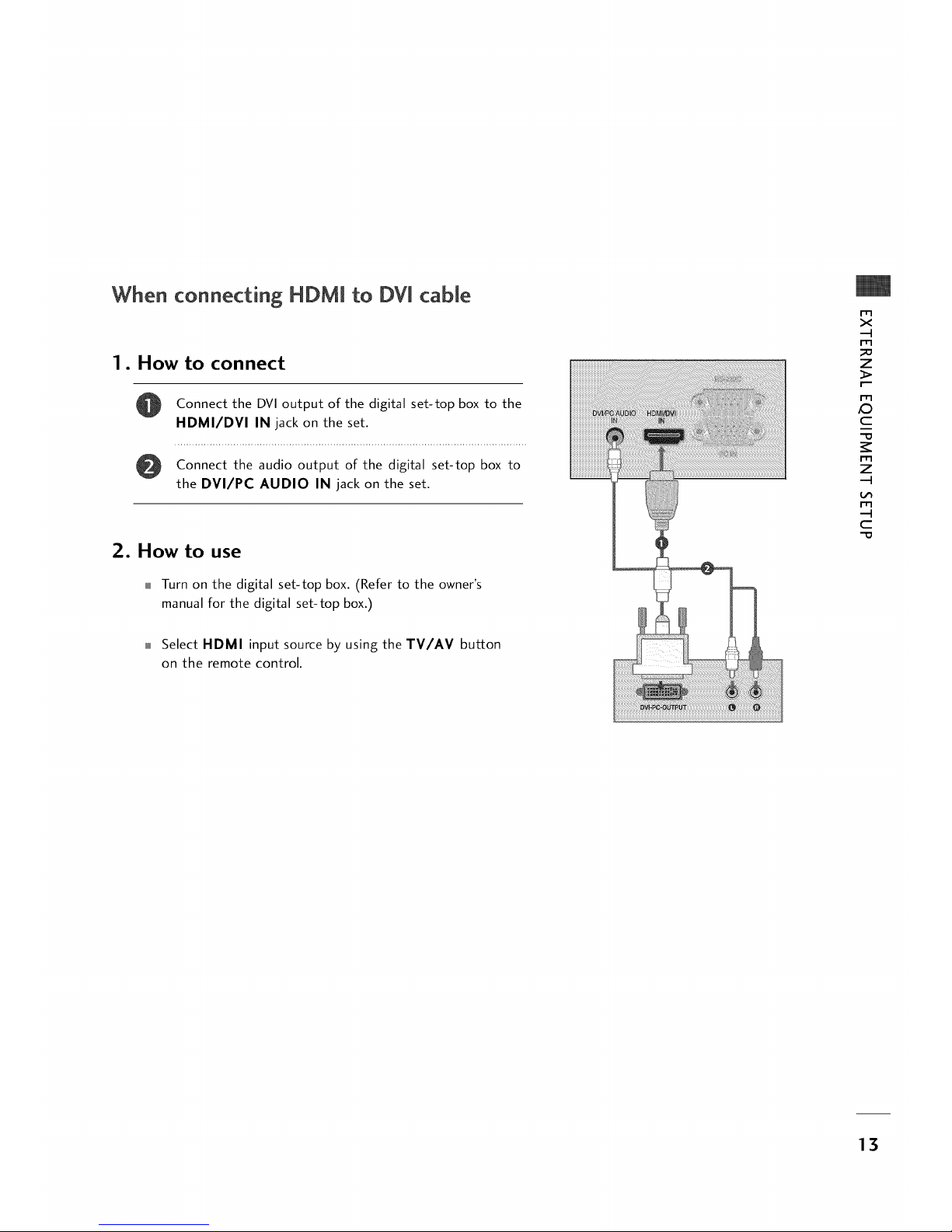
When connecting HDMI to DVl cable
1. How to connect
0
Connect the DVI output of the digital set-top box to the
HDMI/DVI IN jack on the set.
Connect the audio output of the digital set-top box to
the DVI/PC AUDIO IN jack on the set.
2. How to use
Turn on the digital set-top box. (Refer to the owner's
manual for the digital set-top box.)
Select HDMI input source by using the TV/AV button
on the remote control.
m
x
-4
m
_o
z
I_-
m
_D
c
m
z
-4
m
-4
c
13
EXTERNALEQUIPMENT SETUP
DVD SETUP
rT1
x
-4
rT1
_o
z
m
_D
c
rT1
z
-4
m
-4
C
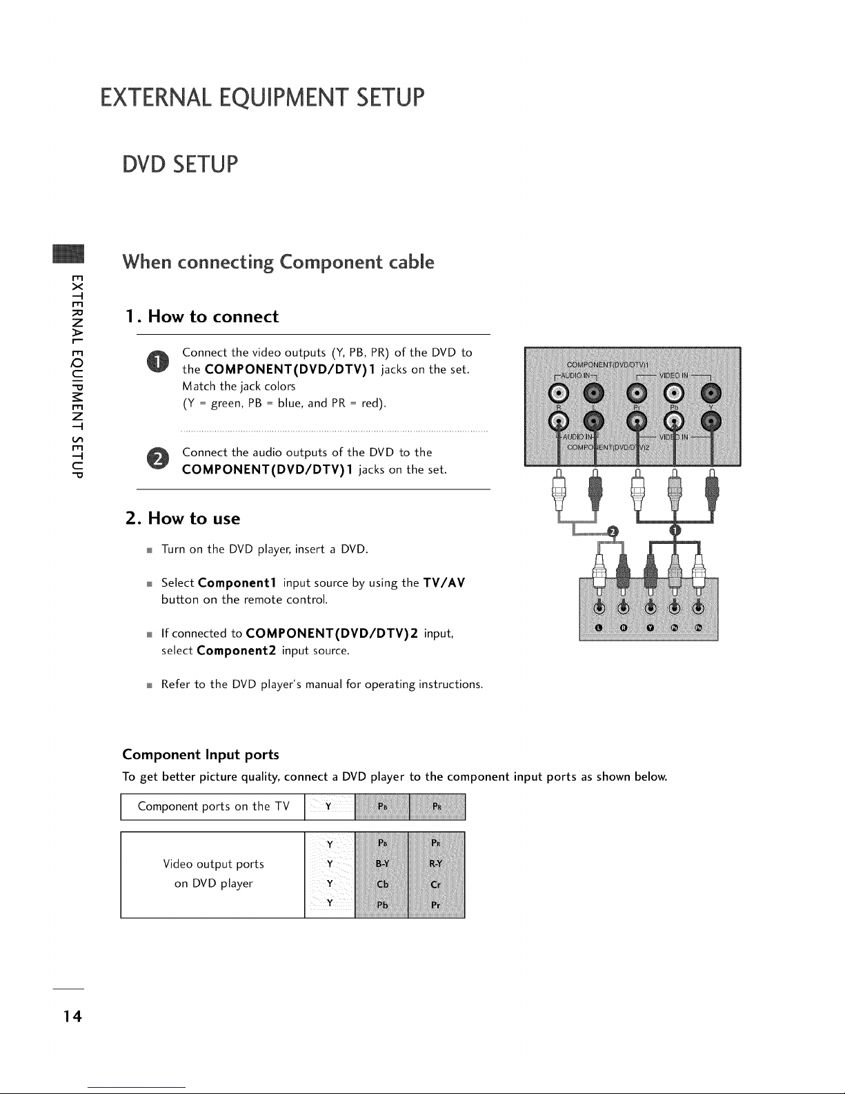
When connecting Component cable
1. How to connect
Connect the video outputs (Y,PB, PR) of the DVD to
the COMPONENT(DVD/DTV)I jacks on the set.
Match the jack colors
(¥ = green, PB = blue, and PR= red).
Connect the audio outputs of the DVD to the
COMPONENT(DVD/DTV)I jacks on the set.
2. How to use
Turn on the DVD player, insert a DVD.
Select Component1 input source by using the TV/AV
button on the remote control.
If connected to COMPONENT(DVD/DTV)2 input,
select Component2 input source.
Refer to the DVD player's manual for operating instructions.
Component Input ports
To get better picture quality, connect a DVD player to the component input ports as shown below.
Component ports on
the TV
Video output ports
on DVD player
14
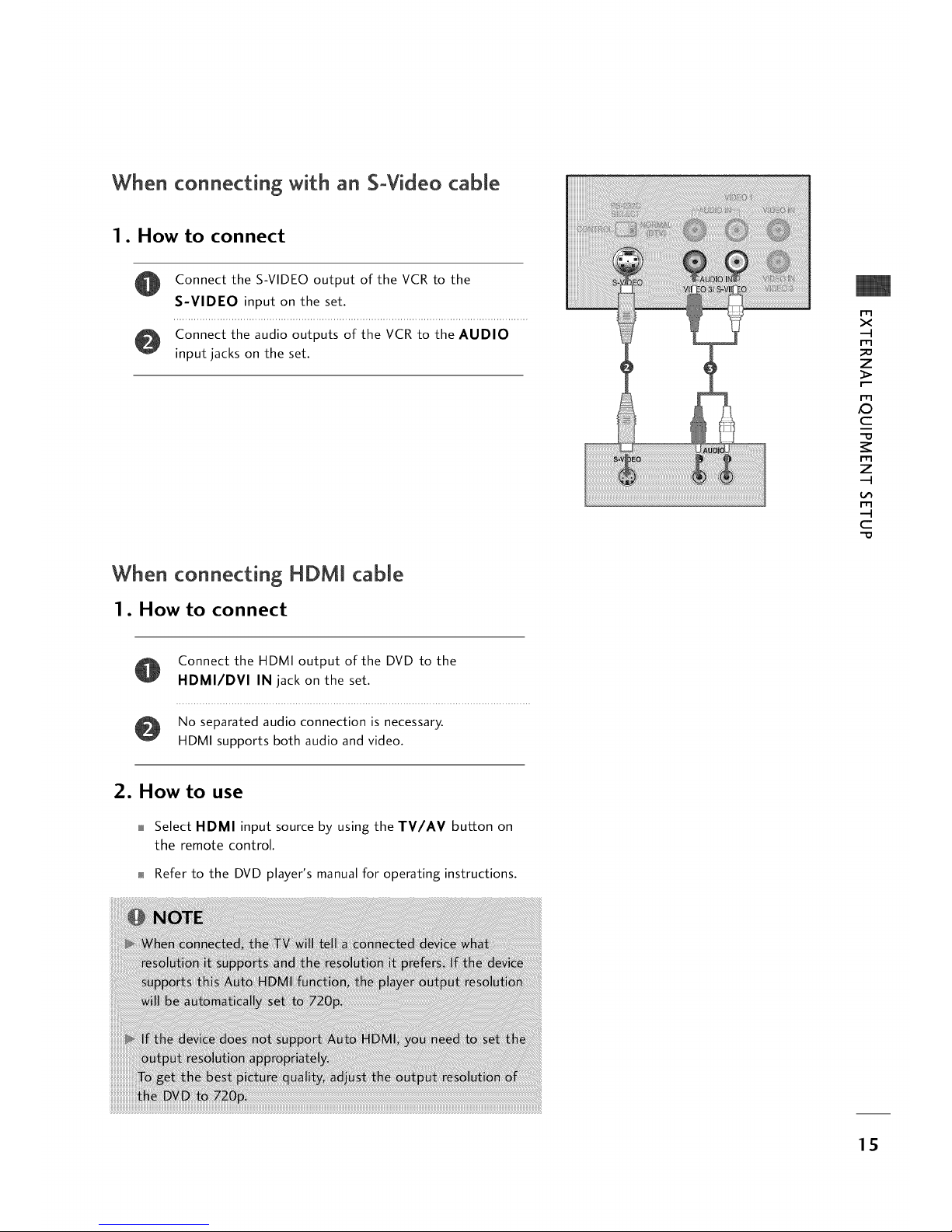
When connecting with an SoVideo cable
1. How to connect
@
Connect the S-VIDEO output of the VCR to the
S-VIDEO input on the set.
Connect the audio outputs of the VCR to the AUDIO
input jacks on the set.
I iiiiiiiiiiiiii!i!
ii!iii!!ii!iii!ilili!iiiiiiii
iiiiiiii!iiiiiii iiiiiiiiiiiiiiiiiiiiiiiiiiiiiiiiiiiiiiiiiiiiiiiiiiiiiiiiiiiiiiiiiiiiiiiiiiiiiiiiiiiiiiii!i!
_:__i_i_i_iiiiiii_i_i_i_iiiiiiiiiiiiiiiiiiii_ii_ii_iiiiiiiiiiii_iiiiiiiiiiiiiiiiiiiiii_i_i_i_i!i!i!iiiiiiiiiiiiiiiiiiiiiiiiiiiiiiiiiiiiilili!i!i!iiiiiiiiiii
_!_ili!i¸ _i_i_i_iiiilililiiiii!i!!i!i_ !i!i
i!iiiiiiiiiiiiiiiiiiiiiiiiiiiiiiiii!i!iiiiiiiii!ii!i!i
iiiiiiiiiiiiiiiiiiiiiii!_!ii_i
ii!ii!ii!ii!ii!i!i!ii!ii!
i!iiiii!ii!iiiiiiiiiiiiiiiiii!i!!!!!ii!iiiii!i!iii!i!ii_!_!_i_!_!!i!i_!!i!!!!!!i!ii_ii!ii!ii!ii!ii!ii!ii!ii!ii!ii!ii!ii!ii!ii!ii!iiiiiiiiiiiiiiiiiii!iii_ii!i!iiiiii_i_i
_i!i!_!_!_i!_i!_i!_i!_!_i!_i!ii!_!_ii_i_i!_!_i!iii!_i!_i!_i!_i!_i!_i_i _
_ _= _ _zzz_ ¸
m
x
-4
m
_o
z
m
X_
c
m
z
-4
m
-4
c
When connecting HDM[ cable
1. How to connect
Connect the HDMI output of the DVD to the
HDMI/DVI IN jack on the set.
No separated audio connection is necessary.
HDMI supports both audio and video.
2. How to use
Select HDMI input source by using the TV/AV button on
the remote control.
Refer to the DVD player's manual for operating instructions.
15
EXTERNALEQUIPMENT SETUP
VCR SETUP
m
x
-4
m
z
m
c
m
z
-4
m
--4
C
To avoid picture noise (interference), leave an adequate distance between the VCR and TV.
If the 4:3 picture format is used; the fixed images on the sides of the screen may remain visible on the screen.
This phenomenon is common to all manufactures and in consequence the manufactures warranty does not cover
the product bearing this phenomenon.
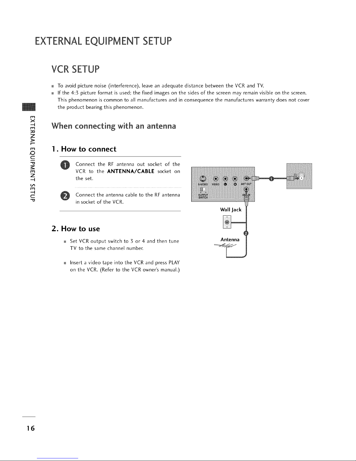
When connecting with an antenna
1. How to connect
o
Connect the RF antenna out socket of the
VCR to the ANTENNA/CABLE socket on
the set.
Connect the antenna cable to the RF antenna
in socket of the VCR.
How to use
Set VCR output switch to 3 or 4 and then tune
TV to the same channel number.
Wall Jack
Antenna
Insert a video tape into the VCR and press PLAY
on the VCR. (Refer to the VCR owner's manual.)
16
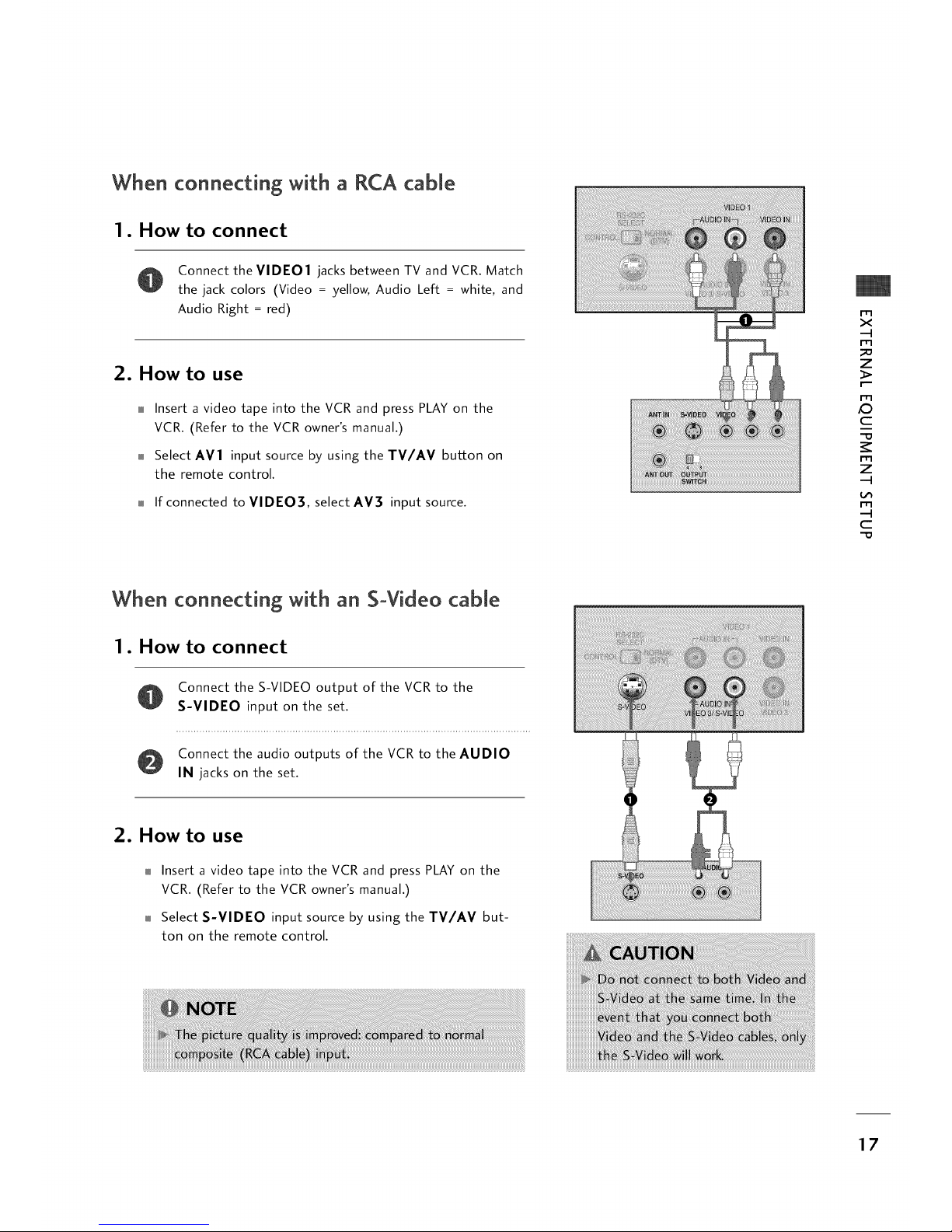
When connecting with a RCA cable
1. How to connect
Connect the VIDE01 jacks between TV and VCR. Match
the jack colors (Video = yellow, Audio Left = white, and
Audio Right = red)
2. How to use
Insert a video tape into the VCR and press PLAY on the
VCR. (Refer to the VCR owner's manual.)
Select AV1 input source by using the TV/AV button on
the remote control.
If connected to VIDEO], select AV3 input source.
m
x
-4
m
_o
z
m
/O
c
-O
m
z
-4
m
-4
C
When connecting with an SoVkteo cable
1. How to connect
Connect the S-VIDEO output of the VCR to the
S-VIDEO input on the set.
Connect the audio outputs of the VCR to the AUDIO
IN jacks on the set.
2. How to use
Insert a video tape into the VCR and press PLAY on the
VCR. (Refer to the VCR owner's manual.)
Select S-VIDEO input source by using the TV/AV but-
ton on the remote control.
17
EXTERNALEQUIPMENT SETUP
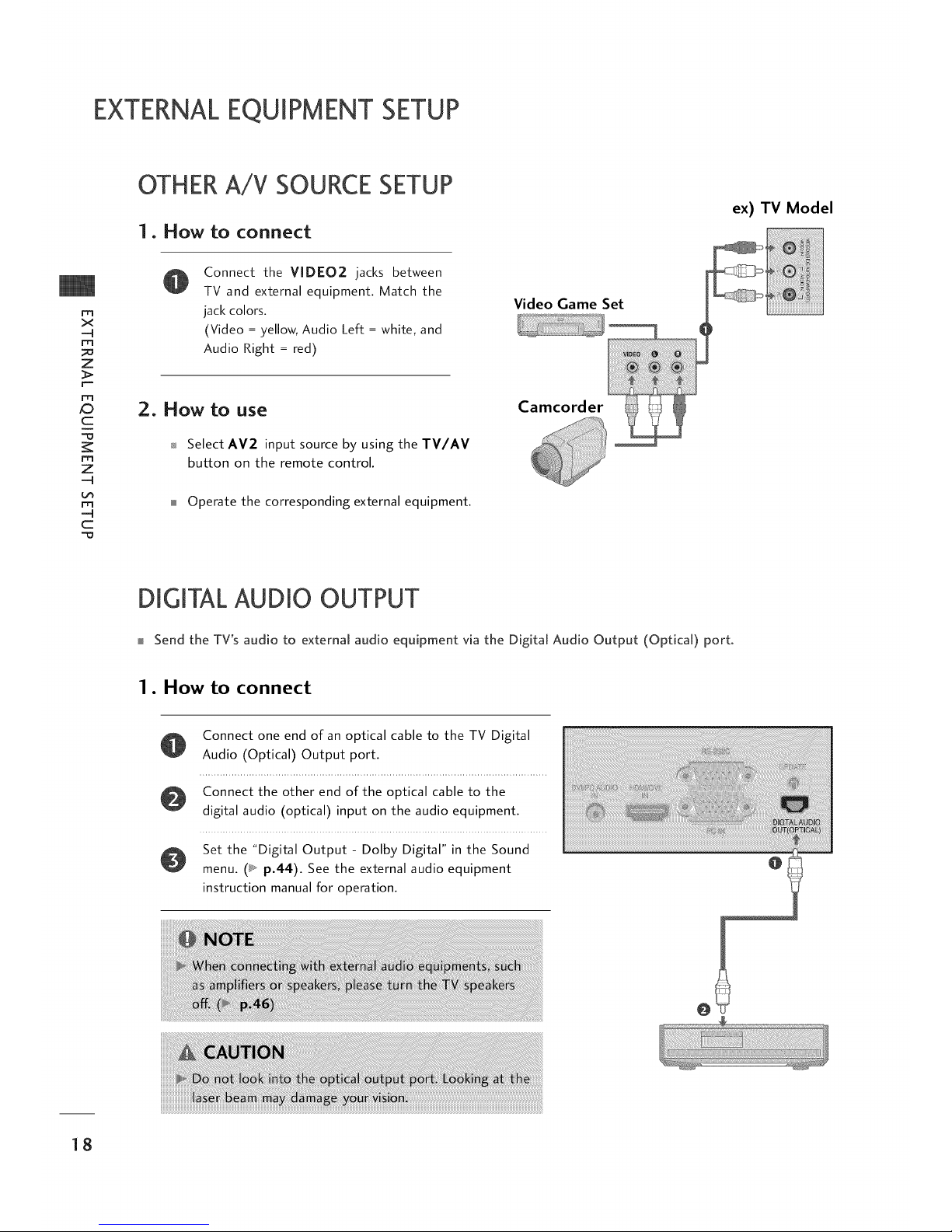
OTHERA/V SOURCESETUP
1. How to connect
ex) TV Model
m
x
-4
m
_o
z
r==
r_3
_D
c
-o
m
z
-4
L_
m
-4
C
-O
Connect the VIDEO2 jacks between
TV and external equipment. Match the
jack colors.
(Video = yellow, Audio Left = white, and
Audio Right = red)
Video Game Set
2. HOW tO use Camcorder
_ Select AV2 input source by using the TV/AV
button on the remote control.
Operate the corresponding external equipment.
DIGITALAUDIO OUTPUT
Send the TV's audio to external audio equipment via the Digital Audio Output (Optical) port.
1. How to connect
@
Connect one end of an optical cable to the TV Digital
Audio (Optical) Output port.
Connect the other end of the optical cable to the
digital audio (optical) input on the audio equipment.
Set the "Digital Output - Dolby Digital" in the Sound
menu. (_, p,44). See the external audio equipment
instruction manual for operation.
18
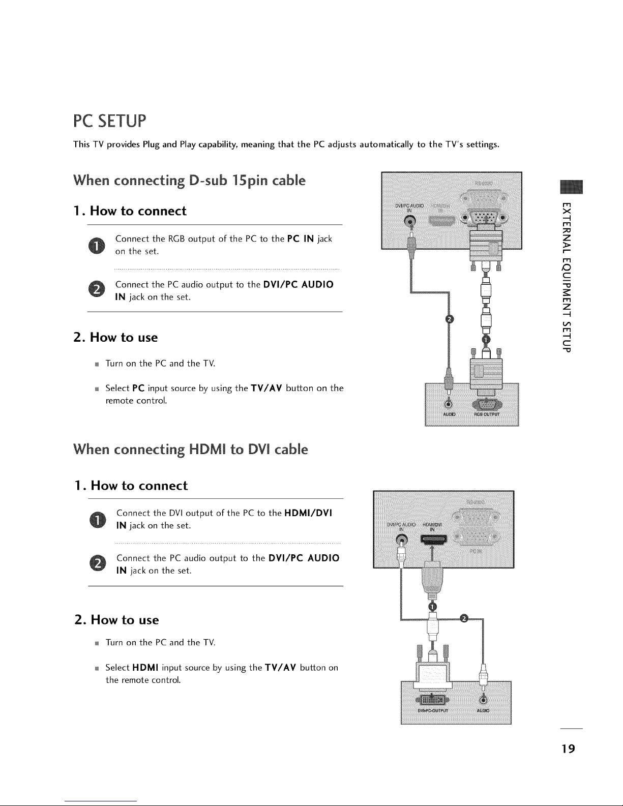
PC SETUP
This TV provides Plug and Play capability, meaning that the PC adjusts automatically to the TV's settings.
When connecting D-sub 1Spin cable
1. How to connect
Connect the RGB output of the PC to the PC IN jack
on the set.
Connect the PC audio output to the DVI/PC AUDIO
IN jack on the set.
2. How to use
Turn on the PC and the TV.
Select PC input source by using the TV/AV button on the
remote control.
m
x
-4
m
_o
z
m
_D
c
-O
m
z
-4
m
-4
C
-O
When connecting HDMi to DVi cable
1. How to connect
Connect the DVI output of the PC to the HDMI/DVI
IN jack on the set.
Connect the PC audio output to the DVI/PC AUDIO
IN jack on the set.
2. How to use
Turn on the PC and the TV.
Select HDMI input source by using the TV/AV button on
the remote control.
19
EXTERNALEQUIPMENT SETUP
m
X
-4
m
_o
z
m
_D
C
-O
m
z
-4
m
-4
C
-O
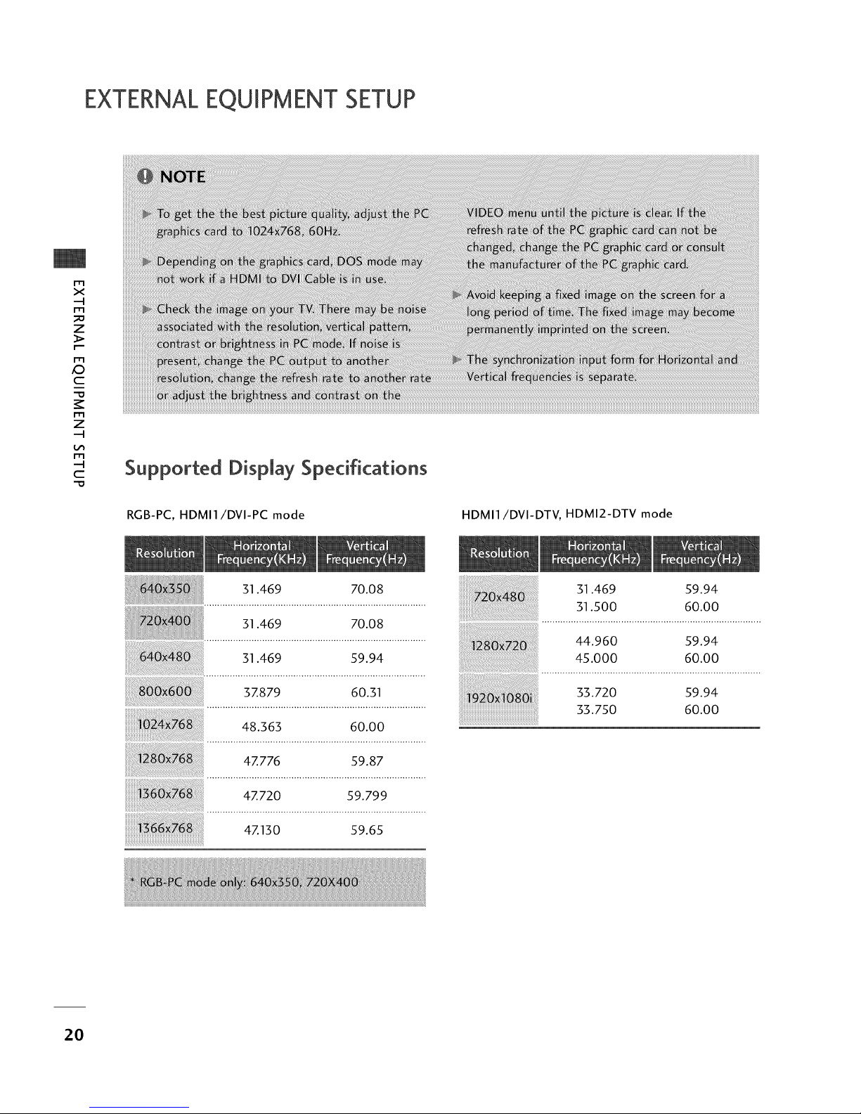
Supported Display Specifications
RGB-PC, HDMI1/DVI-PC mode HDMI1/DVI-DTV, HDMI2-DTV mode
31.469 70.08
31.469 70.08
31.469 59.94
37.879 60.31
48.363 60.00
iiiiii
4Z776 59.87
4Z720 59.799
4Z130 59.65
31.469 59.94
31.500 60.00
44.960 59.94
45.000 60.00
33.720 59.94
33.750 60.00
2O
SCREENSETUPFORPCMODE
Overview
When the RGB input of the set is connected to a PC output,
select the RGB-PC as the main input mode.
When HDMI/DVl connect to PC output and select HDMI/DVl
input, this function is used.
After connecting RGB-PC or HDMI/DVl to PC input and
checking the screen quality.
When you change the resolution, select the proper resolution
in pre-sent input to see the best picture appearance.
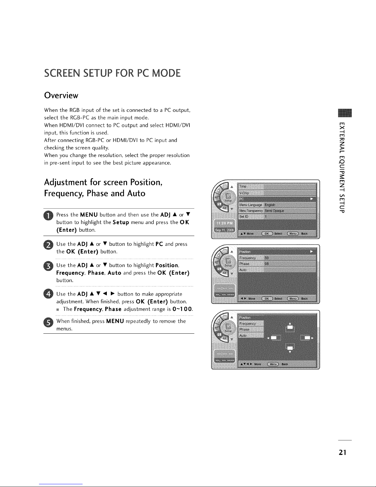
Adjustment for screen Position,
Frequency, Phase and Auto
Press the MENU button and then use the ADJ • or •
button to highlight the Setup menu and press the OK
(Enter) button.
O
Use the ADJ • or • button to highlight PC and press
the OK (Enter) button.
Use the ADJ • or • button to highlight Position,
Frequency, Phase, Auto and press the OK (Enter)
button.
O Use the ADJ button to make appropriate
adjustment. When finished, press OK (Enter) button.
The Frequency, Phase adjustment range is 0~100.
O hen finished, press MENU repeatedly to remove the
menus.
m
x
-q
m
z
I"
m
iO
c
J
-O
m
z
-q
m
-q
c
"O
21
EXTERNALEQUIPMENT SETUP
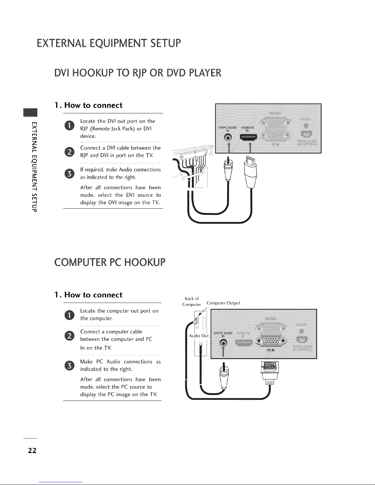
DVl HOOKUP TO RiP OR DVD PLAYER
m
X
-4
m
Z
m
_D
C
m
Z
-4
rT1
-4
C
1. How to connect
@
Locate the DVI out port on the
RiP (Remote Jack Pack) or DVl
device.
Connect a DVI cable between the
RiP and DVI in port on the TV.
If required, make Audio connections
as indicated to the right.
After all connections have been
made, select the DVI source to
display the DVI image on the TV.
COMPUTERPCHOOKUP
1. How to connect
@
Locate the computer out port on
the computer.
Connect a computer cable
between the computer and PC
In on the TV.
Make PC Audio connections as
indicated to the right.
After all connections have been
made, select the PC source to
display the PC image on the TV.
Backof
Computer
Audic
Computer Output
22
TV / CHANNEL CON
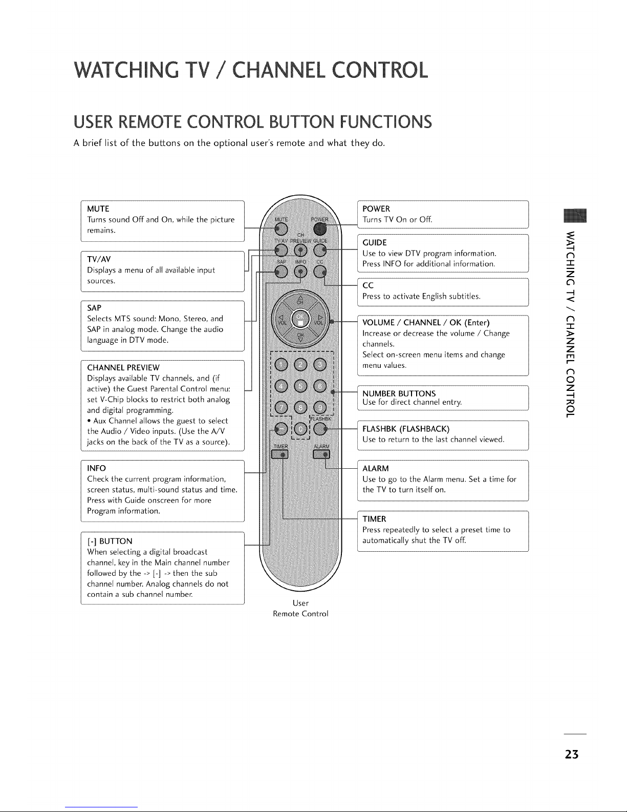
USERREMOTECONTROL BUTTON FUNCTIONS
A brief list of the buttons on the optional user's remote and what they do.
MUTE
Turns sound Off and On, while the picture
remains.
TV/AV
Displays a menu of all available input
sources.
SAP
Selects MTS sound: Mono, Stereo, and
SAP in analog mode. Change the audio
language in DTV mode.
CHANNEL PREVIEW
Displays available TV channels, and (if
active) the Guest Parental Control menu:
set V-Chip blocks to restrict both analog
and digital programming.
• Aux Channel allows the guest to select
the Audio / Video inputs. (Use the A/V
jacks on the back of the TV as a source).
INFO
Check the current program information,
screen status, multi-sound status and time.
Press with Guide onscreen for more
Program information.
[-] BUTTON
When selecting a digital broadcast
channel, key in the Main channel number
followed by the -> [-] -> then the sub
channel number. Analog channels do not
contain a sub channel number.
User
Remote Control
POWER
Turns TV On or Off.
GUIDE
Use to view DTV program information.
Press INFO for additional information.
cc
Pressto activate Englishsubtitles.
VOLUME / CHANNEL / OK (Enter)
Increase or decrease the volume / Change
channels.
Select on-screen menu items and change
menu values.
NUMBER BUTTONS
Use for direct channel entry.
FLASHBK (FLASHBACK)
Use to return to the last channel viewed.
ALARM
Use to go to the Alarm menu. Set a time for
the TV to turn itself on.
TIMER
Press repeatedly to select a preset time to
automatically shut the TV off.
N
-1-
Z
C_
--I
N
-r
Z
Z
rrl
r"""
N
O
Z
--I
O
r"""
23

"CHING
/ CHANNEL CONTROL
INSTALLERREMOTECONTROL BUTTON FUNCTIONS
A brief list of the buttons on the optional installer's remote and what they do.
N
"1"
Z
C_
--I
N
-r
Z
Z
rrl
r"""
N
0
Z
--I
0
r"""
POWER
Turns TV On or Off.
CC (Closed Captioning)
Press to access closed captions.
TV/FM
Not application
VOLUME (-/+)
Decreases/increases sound level.
NUMBER KEYPAD
When selecting a digital broadcast
channel, key in the Main channel
number followed by the -> [-] ->
then the sub channel number.
Analog channels do not contain a
sub channel number.
TIMER
Press repeatedly to select a preset
time to automatically shut the TV
off.
MENU/SELECT/ADJ (Adjust)
Press to display the main on-screen
menu.
Use SELECT to choose an option
and ADJ (adjust) Left/Right to
change the selected option.
FLASHBK (Flashback)
Returns to the previous channel
viewed.
MUTE
Turns sound Off and On, while the
picture remains.
CHANNEL (-/+)
Tunes to next available channel.
ENTER (OK)
Press to view the Channel/Time
display or to remove any on-screen
display or menu.
ALARM
Use to go to the Alarm menu. Set a
time for the TV to turn itself on.
CHANNEL PREVIEW
Displays available TV channels, and
(if active) the Guest Parental Control
menu: set V-Chip blocks to restrict
both analog and digital programming.
• Aux Channel allows the guest to
select the Audio / Video inputs.
(Use the A/V jacks on the back of
the TV as a source).
Installer
Remote Control
24
 Loading...