

LG 26LG40-UA User Manual
Please read this manual carefully before operating
your set and retain it for future reference.
Write the model number and serial number from the
label on the back cabinet on the front or back of
this manual.
LCD TV / DVD Combo
OWNER’S MANUAL
26LG40
32LG40
P/NO : SAC31712401 (0807-REV05)
www.lgusa.com / www.lg.ca
As an ENERGY STAR
Partner LG Electronics USA,
Inc. has determined that
this product meets the
ENERGY STAR guidelines
for energy efficiency.
CAUTION - CLASS 1M VISIBLE
AND INVISIBLE LASER RADIATION
WHEN OPEN DO NOT VIEW DIRECTLY
WITH OPTICAL INSTRUMENTS
ENERGY STAR is a set of power-saving
guidelines issued by the U.S.
Environmental Protection Agency (EPA).
A
WARNING / CAUTION
WARNING / CAUTION
To prevent fire or shock hazards, do not expose
this product to rain or moisture.
FCC NOTICE
Class B digital device
This equipment has been tested and found to comply
with the limits for a Class B digital device, pursuant to
Part 15 of the FCC Rules. These limits are designed
to provide reasonable protection against harmful
interference in a residential installation. This equipment
generates, uses and can radiate radio frequency energy
and, if not installed and used in accordance with the
instructions, may cause harmful interference to radio
communications. However, there is no guarantee that
interference will not occur in a particular installation.
If this equipment does cause harmful interference to
radio or television reception, which can be determined
by turning the equipment off and on, the user is
encouraged to try to correct the interference by one
or more of the following measures:
- Reorient or relocate the receiving antenna.
- Increase the separation between the equipment and
receiver.
- Connect the equipment to an outlet on a circuit
different from that to which the receiver is connected.
- Consult the dealer or an experienced radio/TV
technician for help.
Any changes or modifications not expressly approved
by the party responsible for compliance could void
the user’s authority to operate the equipment.
CAUTION
Do not attempt to modify this product in any way
without written authorization from LG Electronics.
Unauthorized modification could void the user’s
authority to operate this product
The lightning flash with arrowhead
symbol, within an equilateral triangle, is
intended to alert the user to the presence
of uninsulated “dangerous voltage” within the
product’s enclosure that may be of sufficient
magnitude to constitute a risk of electric shock to
persons.
The exclamation point within an equilateral
triangle is intended to alert the user to
the presence of important operating and
maintenance (servicing) instructions in the literature accompanying the appliance.
TO REDUCE THE RISK OF ELECTRIC SHOCK
DO NOT REMOVE COVER (OR BACK). NO
USER SERVICEABLE PARTS INSIDE. REFER TO
QUALIFIED SERVICE PERSONNEL.
WARNING/CAUTION
TO REDUCE THE RISK OF FIRE AND ELECTRIC
SHOCK, DO NOT EXPOSE THIS PRODUCT TO
RAIN OR MOISTURE.
NOTE TO CABLE/TV INSTALLER
This reminder is provided to call the CATV system
installer’s attention to Article 820-40 of the National
Electric Code (U.S.A.). The code provides guidelines for
proper grounding and, in particular, specifies that the
cable ground shall be connected to the grounding system
of the building, as close to the point of the cable entry
as practical.
1
IMPORTANT SAFETY INSTRUCTIONS
SAFETY INSTRUCTIONS
Read these instructions.
Keep these instructions.
Heed all warnings.
Follow all instructions.
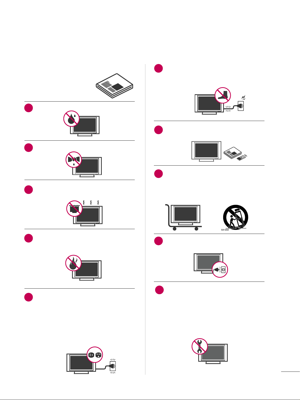
Do not use this apparatus near water.
Clean only with dry cloth.
Do not block any ventilation openings. Install in
accordance with the manufacturer’s instructions.
Do not install near any heat sources such as
radiators, heat registers, stoves, or other
apparatus (including amplifiers)that produce
heat.
Do not defeat the safety purpose of the polarized
or grounding-type plug. A polarized plug has
two blades with one wider than the other. A
grounding type plug has two blades and a
third grounding prong, The wide blade or the
third prong are provided for your safety. If the
provided plug does not fit into your outlet,
consult an electrician for replacement of the
obsolete outlet.
Protect the power cord from being walked on
or pinched particularly at plugs, convenience
receptacles, and the point where they exit from
the apparatus.
Only use attachments/accessories specified by
the manufacturer.
Use only with the cart, stand, tripod, bracket,
or table specified by the manufacturer, or sold
with the apparatus. When a cart is used, use
caution when moving the cart/apparatus combination to avoid injury from tip-over.
Unplug this apparatus during lighting storms
or when unused for long periods of time.
Refer all servicing to qualified service personnel.
Servicing is required when the apparatus has
been damaged in any way, such as powersupply cord or plug is damaged, liquid has
been spilled or objects have fallen into the
apparatus, the apparatus has been exposed to
rain or moisture, does not operate normally, or
has been dropped.
1
2
3
4
5
7
8
6
9
10
2
SAFETY INSTRUCTIONS
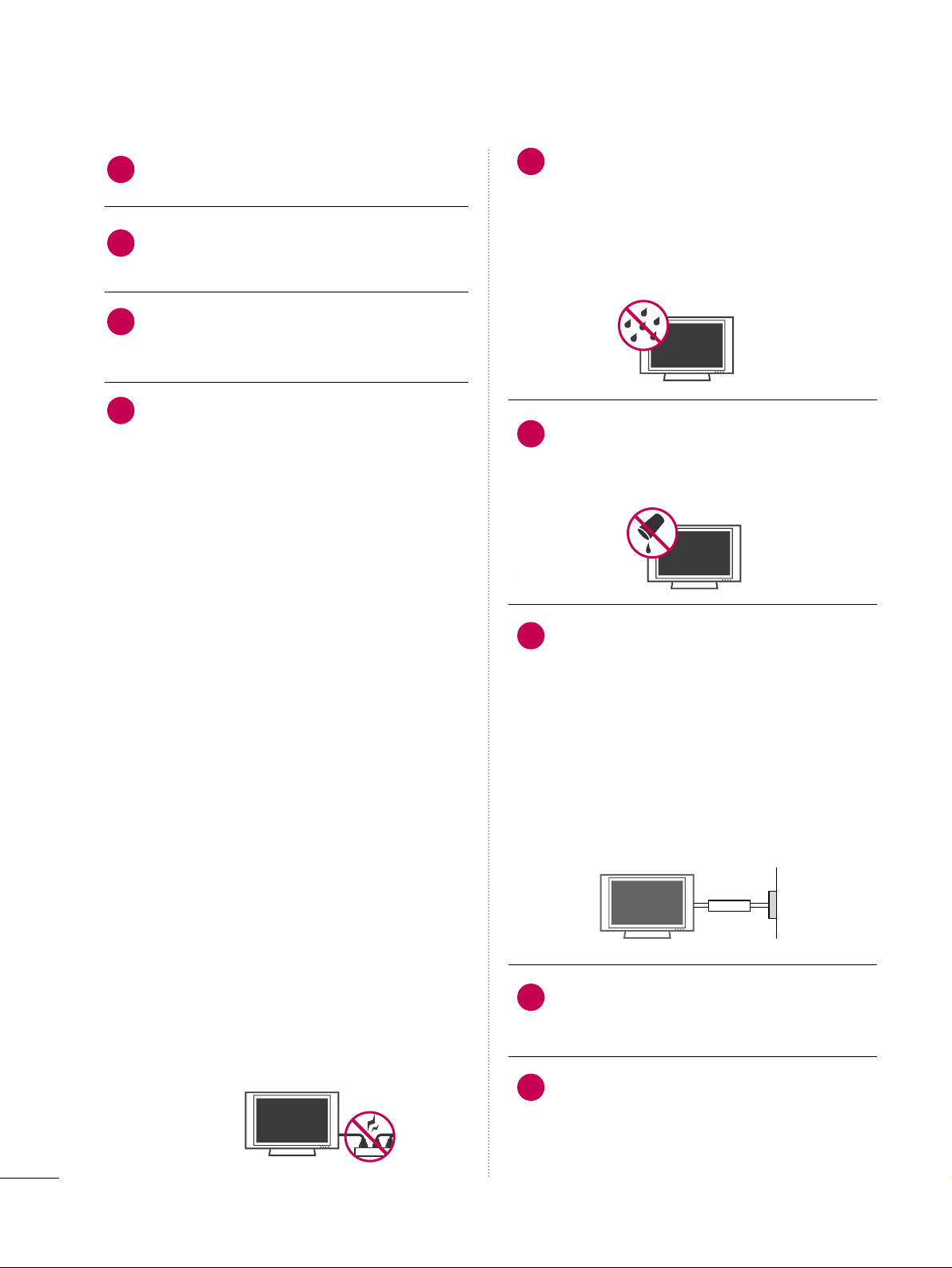
Never touch this apparatus or antenna during
a thunder or lighting storm.
When mounting a TV on the wall, make sure
not to install the TV by the hanging power and
signal cables on the back of the TV.
Do not allow an impact shock or any objects to
fall into the product, and do not drop onto the
screen with something.
CAUTION concerning the Power Cord:
It is recommend that appliances be placed
upon a dedicated circuit; that is, a single
outlet circuit which powers only that appliance
and has no additional outlets or branch
circuits. Check the specification page of this
owner's manual to be certain.
Do not connect too many appliances to the
same AC power outlet as this could result in
fire or electric shock.
Do not overload wall outlets. Overloaded wall
outlets, loose or damaged wall outlets, extension
cords, frayed power cords, or damaged or
cracked wire insulation are dangerous. Any of
these conditions could result in electric shock
or fire. Periodically examine the cord of your
appliance, and if its appearance indicates damage
or deterioration, unplug it, discontinue use of
the appliance, and have the cord replaced with
an exact replacement part by an authorized
servicer. Protect the power cord from physical
or mechanical abuse, such as being twisted,
kinked, pinched, closed in a door, or walked
upon. Pay particular attention to plugs, wall
outlets, and the point where the cord exits the
appliance.
Do not make the TV with the power cord
plugged in. Do not use a damaged or loose
power cord. Be sure do grasp the plug when
unplugging the power cord. Do not pull on the
power cord to unplug the TV.
WARNING - To reduce the risk of fire or electrical
shock, do not expose this product to rain,
moisture or other liquids. Do not touch the TV
with wet hands. Do not install this product
near flammable objects such as gasoline or
candles or expose the TV to direct air
conditioning.
Do not expose to dripping or splashing and do
not place objects filled with liquids, such as
vases, cups, etc. on or over the apparatus (e.g.
on shelves above the unit).
GGRROOUUNNDDII NNGG
Ensure that you connect the earth ground wire
to prevent possible electric shock (i.e. a TV
with a three-prong grounded AC plug must be
connected to a three-prong grounded AC outlet). If grounding methods are not possible,
have a qualified electrician install a separate
circuit breaker.
Do not try to ground the unit by connecting it
to telephone wires, lightening rods, or gas
pipes.
DDIISSCCOONNNNEECCTTIINNGG DDEEVVIICCEE FFRROOMM MMAAIINNSS
Mains plug is the disconnecting device. The
plug must remain readily operable.
Keep the product away from direct sunlight.
12
11
14
13
16
17
18
19
Power
Supply
Short-circuit
Breaker
15
3
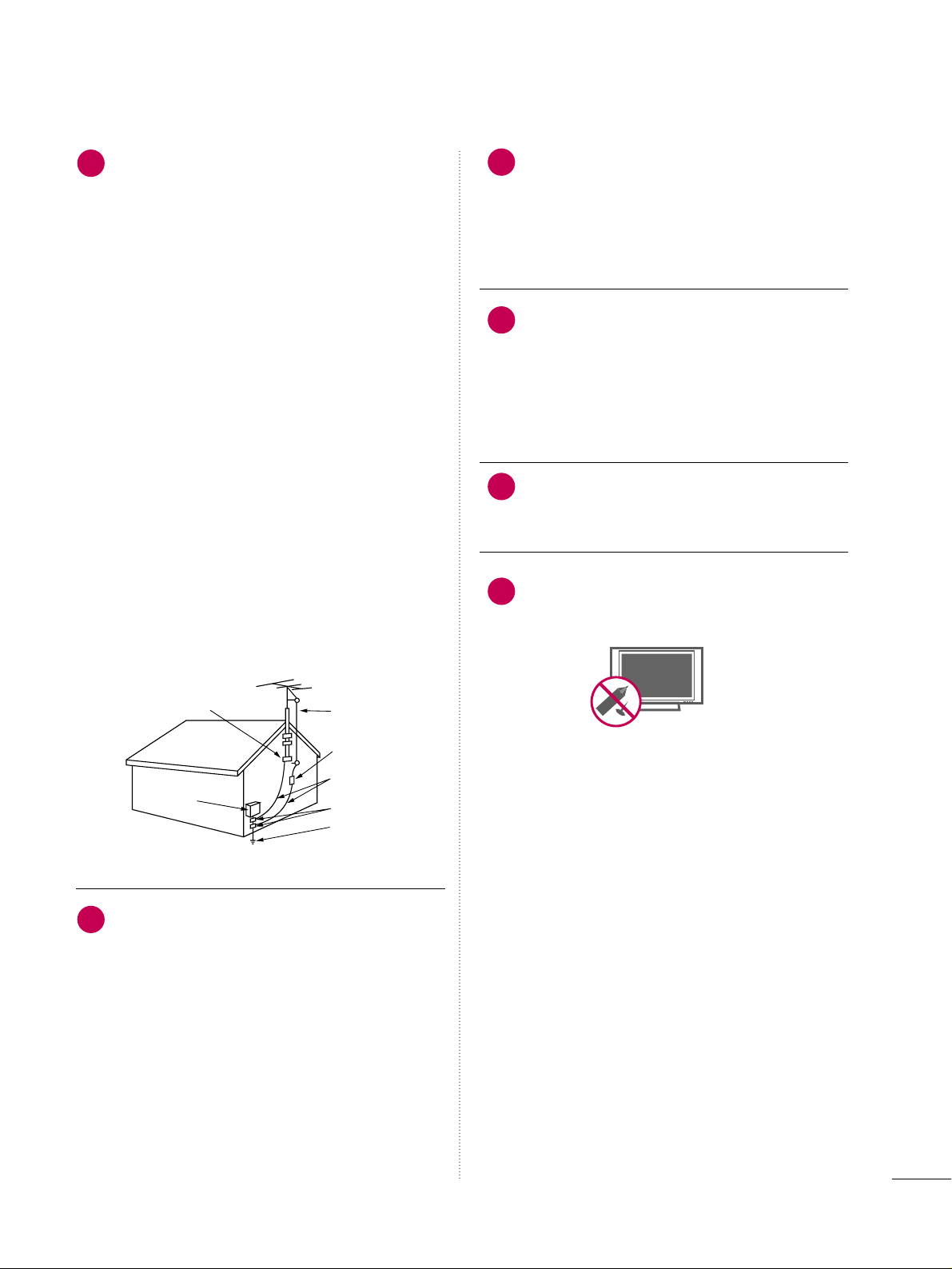
AANN TTEENNNNAASS
OOuuttddoooorr aanntteennnnaa ggrroouunnddiinngg
If an outdoor antenna is installed, follow the
precautions below. An outdoor antenna system
should not be located in the vicinity of overhead power lines or other electric light or
power circuits, or where it can come in contact
with such power lines or circuits as death or
serious injury can occur.
Be sure the antenna system is grounded so as
to provide some protection against voltage
surges and built-up static charges.
Section 810 of the National Electrical Code
(NEC) in the U.S.A. provides information with
respect to proper grounding of the mast and
supporting structure, grounding of the lead-in
wire to an antenna discharge unit, size of
grounding conductors, location of antenna discharge unit, connection to grounding electrodes and requirements for the grounding
electrode.
AAnntteennnnaa ggrroouunnddiinngg aaccccoorrddiinngg ttoo tthhee
NNaattiioonnaall EElleeccttrriiccaall CCooddee,, AANNSSII//NNFFPPAA 7700
CClleeaa nniinngg
When cleaning, unplug the power cord and
scrub gently with a soft cloth to prevent
scratching. Do not spray water or other liquids
directly on the TV as electric shock may occur.
Do not clean with chemicals such as alcohol,
thinners or benzene.
MMoovviinngg
Make sure the product is turned off,
unplugged and all cables have been removed. It
may take 2 or more people to carry larger TVs.
Do not press against or put stress on the front
panel of the TV.
VVeennttiillaattiioonn
Install your TV where there is proper ventila-
tion. Do not install in a confined space such as
a bookcase. Do not cover the product with
cloth or other materials (e.g.) plastic while
plugged in. Do not install in excessively dusty
places.
If you smell smoke or other odors coming from
the TV or hear strange sounds, unplug the power
cord contact an authorized service center.
Do not press strongly upon the panel with
hand or sharp object such as nail, pencil or
pen, or make a scratch on it.
22
20
23
24
25
21
Antenna Lead in Wire
Antenna Discharge Unit
(NEC Section 810-20)
Grounding Conductor
(NEC Section 810-21)
Ground Clamps
Power Service Grounding
Electrode System (NEC
Art 250, Part H)
Ground Clamp
Electric Service
Equipment
NEC: National Electrical Code

4
CONTENTS
WARNING / CAUTION
. . . . . . . . . . . . . . . . . . . . . . . . . . . . A
SAFETY INSTRUCTIONS
. . . . . . . . . . . . . . . . . . . . . . . . . . 1
PREPARATION
Accessories
. . . . . . . . . . . . . . . . . . . . . . . . . . . . . . . . . . . . . . . . . . . . . . . . . . . . . . 7
Front Panel Information
. . . . . . . . . . . . . . . . . . . . . . . . . . . . . . . . . . . . .8
Back Panel Information
. . . . . . . . . . . . . . . . . . . . . . . . . . . . . . . . . . . . . .
9
Stand Instruction
. . . . . . . . . . . . . . . . . . . . . . . . . . . . . . . . . . . . . . . . . . . . . 10
Cable Management
. . . . . . . . . . . . . . . . . . . . . . . . . . . . . . . . . . . . . . . . . .
11
Desktop Pedestal Installation
. . . . . . . . . . . . . . . . . . . . . . . . . . . .12
Swivel Stand
. . . . . . . . . . . . . . . . . . . . . . . . . . . . . . . . . . . . . . . . . . . . . . . . . . . . 12
Attaching the TV to a Desk
. . . . . . . . . . . . . . . . . . . . . . . . . . . . . .
12
VESA Wall Mounting
. . . . . . . . . . . . . . . . . . . . . . . . . . . . . . . . . . . . . . . . 13
Securing the TV to the wall to prevent falling when
the TV is used on a stand
. . . . . . . . . . . . . . . . . . . . . . . . . . . . . . . . 14
Antenna or Cable Connection
. . . . . . . . . . . . . . . . . . . . . . . . . .
15
EXTERNAL EQUIPMENT SETUP
HD Receiver Setup
. . . . . . . . . . . . . . . . . . . . . . . . . . . . . . . . . . . . . . . . . 16
DVD Setup . . . . . . . . . . . . . . . . . . . . . . . . . . . . . . . . . . . . . . . . . . . . . . . . . . . . . .19
VCR Setup
. . . . . . . . . . . . . . . . . . . . . . . . . . . . . . . . . . . . . . . . . . . . . . . . . . . . .
21
Other A/V Source Setup . . . . . . . . . . . . . . . . . . . . . . . . . . . . . . . . . 23
Audio out Connection
. . . . . . . . . . . . . . . . . . . . . . . . . . . . . . . . . . . . .
24
PC Setup
. . . . . . . . . . . . . . . . . . . . . . . . . . . . . . . . . . . . . . . . . . . . . . . . . . . . . . . .
25
WATCHING TV / CHANNEL CONTROL
Remote Control Functions
. . . . . . . . . . . . . . . . . . . . . . . . . . . . . . . 32
Turning On TV
. . . . . . . . . . . . . . . . . . . . . . . . . . . . . . . . . . . . . . . . . . . . . . . . 34
Channel Selection
. . . . . . . . . . . . . . . . . . . . . . . . . . . . . . . . . . . . . . . . . . . 34
Volume Adjustment
. . . . . . . . . . . . . . . . . . . . . . . . . . . . . . . . . . . . . . . . .
34
Quick Menu
. . . . . . . . . . . . . . . . . . . . . . . . . . . . . . . . . . . . . . . . . . . . . . . . . . . . 35
Initial Setting . . . . . . . . . . . . . . . . . . . . . . . . . . . . . . . . . . . . . . . . . . . . . . . . . .
36
On-Screen Menus Selection
. . . . . . . . . . . . . . . . . . . . . . . . . . . . .
37
Channel Setup
- Auto Scan (Auto Tuning)
. . . . . . . . . . . . . . . . . . . . . . . . . . .
38
- Add / Delete Channel (Manual Tuning)
. . . . . .
39
- Channel Editing
. . . . . . . . . . . . . . . . . . . . . . . . . . . . . . . . . . . . . . . . 40
Input List
. . . . . . . . . . . . . . . . . . . . . . . . . . . . . . . . . . . . . . . . . . . . . . . . . . . . . . . .
41
Input Label
. . . . . . . . . . . . . . . . . . . . . . . . . . . . . . . . . . . . . . . . . . . . . . . . . . . . . 42
AV Mode
. . . . . . . . . . . . . . . . . . . . . . . . . . . . . . . . . . . . . . . . . . . . . . . . . . . . . . . . 43
SIMPLINK
. . . . . . . . . . . . . . . . . . . . . . . . . . . . . . . . . . . . . . . . . . . . . . . . . . . . . . .
44
DVD OPERATION
Notes on Discs
. . . . . . . . . . . . . . . . . . . . . . . . . . . . . . . . . . . . . . . . . . . . . . . 46
Selecting Language
- Selecting Audio Language
. . . . . . . . . . . . . . . . . . . . . . . . . 48
- Selecting Subtitle Language
. . . . . . . . . . . . . . . . . . . . . . 49
- Selecting Disc OSD Language
. . . . . . . . . . . . . . . . . . .
50
Parental Control / Ratings
- Parental Control Setup
. . . . . . . . . . . . . . . . . . . . . . . . . . . . . . 51
- Changing the password
. . . . . . . . . . . . . . . . . . . . . . . . . . . . . 52
Picture Size Control
. . . . . . . . . . . . . . . . . . . . . . . . . . . . . . . . . . . . . . . . 53
Digital Audio Output
. . . . . . . . . . . . . . . . . . . . . . . . . . . . . . . . . . . . . . .
54
Dynamic Range Compression (DRC)
. . . . . . . . . . . . . . . . 55
Playing a DVD or Video CD
. . . . . . . . . . . . . . . . . . . . . . . . . . . . . 56
MP3 Operation
. . . . . . . . . . . . . . . . . . . . . . . . . . . . . . . . . . . . . . . . . . . . . . . 59
Audio CD Operation
. . . . . . . . . . . . . . . . . . . . . . . . . . . . . . . . . . . . . . .
60
JPG File Viewing Options
. . . . . . . . . . . . . . . . . . . . . . . . . . . . . . . . . . 61
PICTURE CONTROL
Picture Size (Aspect Ratio) Control
. . . . . . . . . . . . . . . . . .
62
Preset Picture Settings
- Picture Mode - Preset
. . . . . . . . . . . . . . . . . . . . . . . . . . . . . . . 64
- Color Tone - Preset
. . . . . . . . . . . . . . . . . . . . . . . . . . . . . . . . . .
65
Manual Picture Adjustment
- Picture Mode - User Mode
. . . . . . . . . . . . . . . . . . . . . . . .
66
- Picture Mode - Expert Control
. . . . . . . . . . . . . . . . . .
67
Picture Improvement Technology
. . . . . . . . . . . . . . . . . . . . .
68
Advanced Control - Black (Darkness) Level
. . . . . . .
69
Advanced Control - Eye Care
. . . . . . . . . . . . . . . . . . . . . . . . . . . 70
Advanced Control - Real Cinema
. . . . . . . . . . . . . . . . . . . . . . 71
Picture Reset
. . . . . . . . . . . . . . . . . . . . . . . . . . . . . . . . . . . . . . . . . . . . . . . . . 72
Power Indicator
. . . . . . . . . . . . . . . . . . . . . . . . . . . . . . . . . . . . . . . . . . . . . .
73

5
SOUND & LANGUAGE CONTROL
Auto Volume Leveler (Auto Volume) . . . . . . . . . . . . . . . . . 74
Clear Voice
. . . . . . . . . . . . . . . . . . . . . . . . . . . . . . . . . . . . . . . . . . . . . . . . . . . . . 75
Preset Sound Setting (Sound Mode)
. . . . . . . . . . . . . . . . 76
Sound Setting Adjustment - User Mode
. . . . . . . . . . . 77
Balance
. . . . . . . . . . . . . . . . . . . . . . . . . . . . . . . . . . . . . . . . . . . . . . . . . . . . . . . . . .
78
TV Speakers On/Off Setup
. . . . . . . . . . . . . . . . . . . . . . . . . . . . .
79
Audio Reset
. . . . . . . . . . . . . . . . . . . . . . . . . . . . . . . . . . . . . . . . . . . . . . . . . . .80
Stereo/SAP Broadcasts Setup
. . . . . . . . . . . . . . . . . . . . . . . . . . 81
Audio Language
. . . . . . . . . . . . . . . . . . . . . . . . . . . . . . . . . . . . . . . . . . . . . .82
On-Screen Menus Language Selection
. . . . . . . . . . . . . .83
Caption Mode
- Analog Broadcasting System Captions
. . . . . . .
84
- Digital Broadcasting System Captions
. . . . . . . .
85
- Caption Option
. . . . . . . . . . . . . . . . . . . . . . . . . . . . . . . . . . . . . . . 86
TIME SETTING
Clock Setting
- Auto Clock Setup
. . . . . . . . . . . . . . . . . . . . . . . . . . . . . . . . . . . .
87
- Manual Clock Setup
. . . . . . . . . . . . . . . . . . . . . . . . . . . . . . . . . 88
Auto On/Off Time Setting . . . . . . . . . . . . . . . . . . . . . . . . . . . . . .
89
Sleep Timer Setting
. . . . . . . . . . . . . . . . . . . . . . . . . . . . . . . . . . . . . . . . .
90
Auto Shut-off Setting . . . . . . . . . . . . . . . . . . . . . . . . . . . . . . . . . . . . . . .91
PARENTAL CONTROL / RATINGS
Set Password & Lock System
. . . . . . . . . . . . . . . . . . . . . . . . . . .
92
Channel Blocking
. . . . . . . . . . . . . . . . . . . . . . . . . . . . . . . . . . . . . . . . . . . . 95
Movie & TV Rating
. . . . . . . . . . . . . . . . . . . . . . . . . . . . . . . . . . . . . . . . .
96
Downloadable Rating
. . . . . . . . . . . . . . . . . . . . . . . . . . . . . . . . . . . . .
101
External Input Blocking
. . . . . . . . . . . . . . . . . . . . . . . . . . . . . . . . . .
10 2
Key Lock . . . . . . . . . . . . . . . . . . . . . . . . . . . . . . . . . . . . . . . . . . . . . . . . . . . . . . .
10 3
APPENDIX
Troubleshooting
. . . . . . . . . . . . . . . . . . . . . . . . . . . . . . . . . . . . . . . . . . . . 10 4
Maintenance
. . . . . . . . . . . . . . . . . . . . . . . . . . . . . . . . . . . . . . . . . . . . . . . . . 10 6
Product Specifications . . . . . . . . . . . . . . . . . . . . . . . . . . . . . . . . . . .
10 7
Programing the Remote Control
. . . . . . . . . . . . . . . . . . . . . 10 8
IR Code
. . . . . . . . . . . . . . . . . . . . . . . . . . . . . . . . . . . . . . . . . . . . . . . . . . . . . . . . .
111
External Control Through RS-232C
. . . . . . . . . . . . . . . . .113
Open Source License
. . . . . . . . . . . . . . . . . . . . . . . . . . . . . . . . . . . . . .12 0
6
■
If the TV feels cold to the touch, there may be a small “flicker” when it is turned on. This is normal, there is
nothing wrong with TV.
■
Some minute dot defects may be visible on the screen, appearing as tiny red, green, or blue spots. However, they
have no adverse effect on the monitor's performance.
■
Avoid touching the LCD screen or holding your finger(s) against it for long periods of time. Doing so may produce
some temporary distortion effects on the screen.
On Disposal
The fluorescent lamp used in this product contains a small amount of mercury. Do not dispose of this product with
general household waste. Disposal of this product must be carried out in accordance to the regulations of your local
authority.
Manufactured under license from Dolby Laboratories. “
Dolby
“and the double-D symbol are trademarks of Dolby Laboratories.
is a trademark of DVD format/Logo Licensing Corporation.
This product incorporates copy protection technology that is protected by U.S. and foreign patents, including patent numbers 5,315,448
and 6,836,549, and other intellectual property rights. The use of Macrovision's copy protection technology in the product must be authorized by Macrovision. Reverse engineering or disassembly is prohibited."
is a trademark of SRS Labs, Inc.
TruSurround XT technology is incorporated under license from SRS Labs, Inc.
PREPARATION
7
PREPARATION
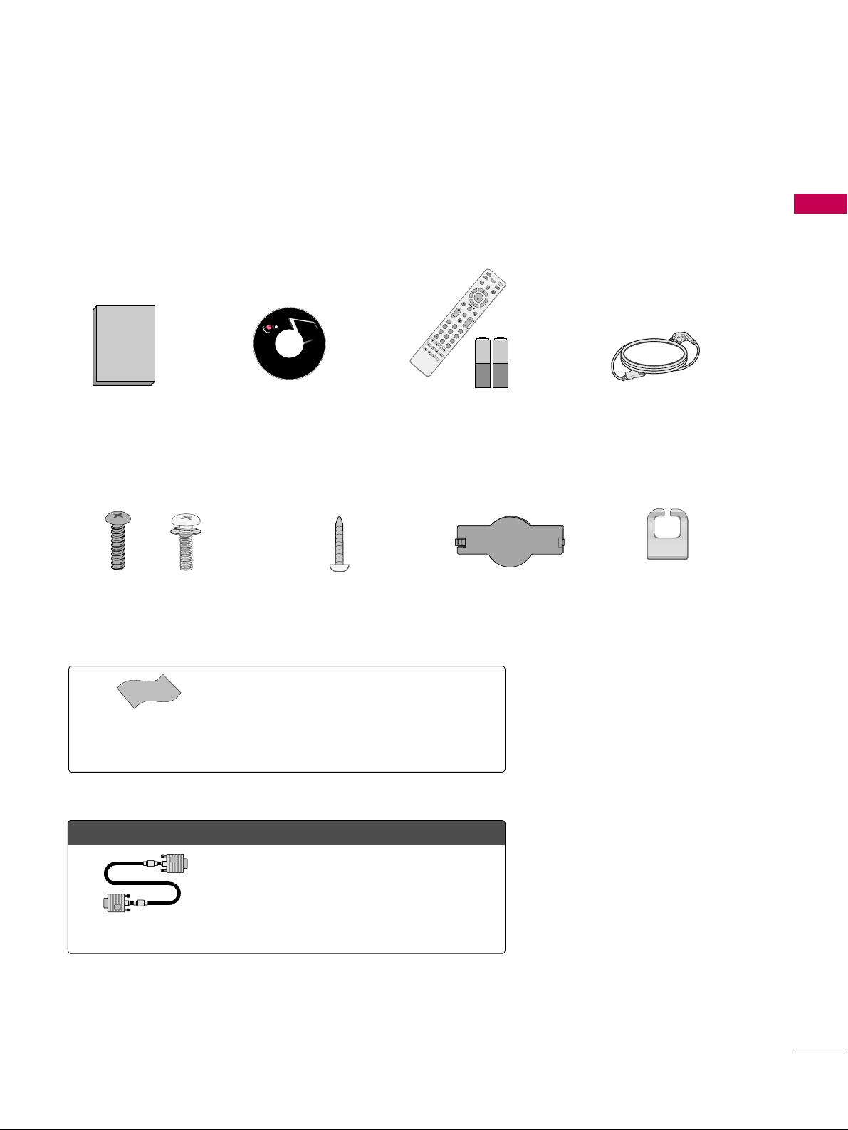
ACCESSORIES
Ensure that the following accessories are included with your TV. If an accessory is missing, please contact the
dealer where you purchased the TV.
The accessories included may differ from the images below.
Copyright© 2007 LGE,
All Rights Reserved.
1.5V 1.5V
Owner’s Manual Power Cord
Remote Control,
Batteries
FAV
M
U
T
E
D
I
S
P
L
A
Y
Z
O
O
M
S
U
B
T
I
T
L
E
S
K
I
P
+
A
U
D
I
O
A
N
G
L
E
R
E
T
U
R
N
R
E
P
E
A
T
A
-
B
T
I
T
L
E
M
E
N
U
A
V
M
O
D
E
R
E
T
U
R
N
NTER
V
O
L
C
H
123
456
0
9
F
L
A
S
H
B
K
P
A
G
E
R
O
T
A
T
E
+
IN
P
U
T
FAV
M
U
T
E
D
I
S
P
L
A
Y
Z
O
O
M
S
U
B
T
I
T
L
E
S
K
I
P
-
S
L
O
W
-
S
K
I
P
+
E
J
E
C
T
S
L
O
W
+
A
U
D
I
O
A
N
G
L
E
P
B
C
R
E
T
U
R
N
R
E
P
E
A
T
A
B
T
I
T
L
E
M
E
N
U
T
V
S
T
B
PO
W
ER
Q
.
M
E
N
U
B
U
IL
T
-I
N
M
E
N
U
/
S
E
T
U
P
A
V
M
O
D
E
R
E
T
U
R
N
ENTER
V
O
L
C
H
123
456
78
0
9
F
L
A
S
H
B
K
P
A
G
E
D
V
D
V
C
R
R
O
T
A
T
E
+
R
O
T
A
T
E
-
D
I
S
C
M
E
N
U
CD Manual
OOppttiioonn EExxttrraass
* Wipe spots on the exterior only with the
polishing cloth.
* Do not wipe roughly when removing stains.
Excessive pressure may cause scratches or
discoloration.
Polishing Cloth
(This feature is not available
for all models.)
D-sub 15 pin Cable
When using the VGA (D-sub 15 pin cable)
PC connection, the user must use shielded
signal interface cables with ferrite cores to
maintain standards compliance.
Bolts for stand assembly
(Refer to P.10)
Screw for stand fixing
(Refer to P.12)
Protection Cover
x 4 x 4
Cable Management
Clip
PREPARATION
8
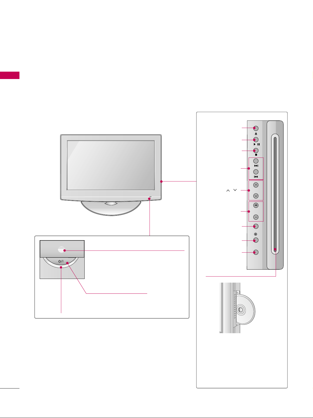
FRONT PANEL INFORMATION
PREPARATION
■
Image shown may differ from your TV.
■
NOTE: If your TV has a protection tape attached, remove the tape.
And then wipe the TV with a cloth (If a polishing cloth is included with your TV, use it).
POWER Button
Power/Standby Indicator
Illuminates red in standby mode.
Illuminates blue when the TV is switched on.
(Can be adjusted. Refer to
PPoowweerr
IInnddiiccaattoorr
in the OPTION menu.
GG
pp..7733
)
CHANNEL ( , )
Buttons
VOLUME (+, -)
Buttons
ENTER Button
EJECT Button
PLAY/PAUSE Button
STOP Button
SKIP Button
MENU Button
INPUT Button
DDiiss cc SS lloott::
Insert discs with the label facing
towards the front of the TV. Press
the disc partially into the slot and
the loader will pull the disc from
your hand. Do not force the disc
into the slot.
Remote Control Sensor
/
CH
VOL
ENTER
MENU
INPUT
PREPARATION
9
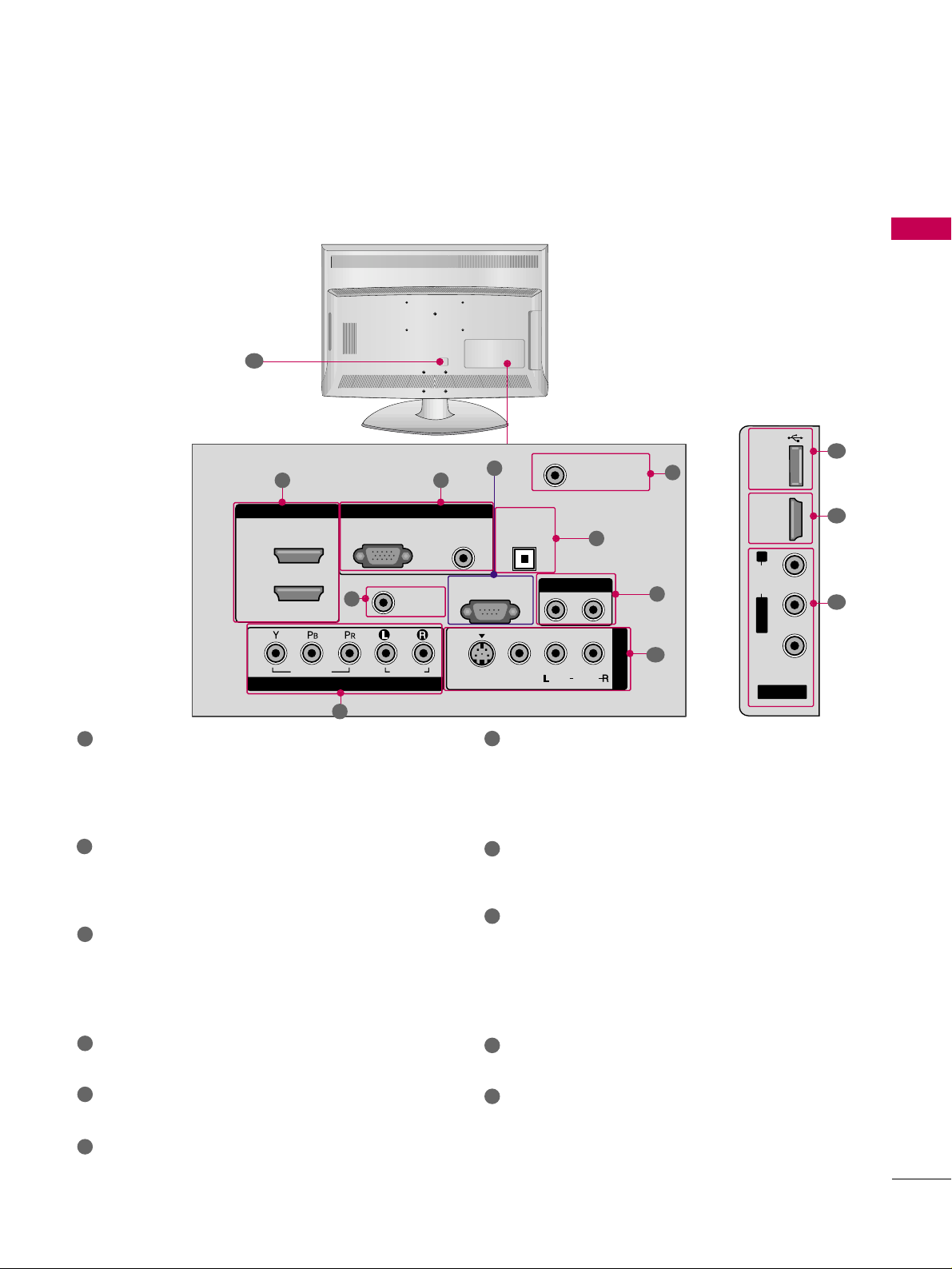
BACK PANEL INFORMATION
■
Image shown may differ from your TV.
R
R
31
4
6
7
8
2
9
5
AV IN 2
L/ MONO
R
AUDIO
VIDEO
USB
SERVUCE ONLY
HDMI IN 3
9
10
1
11
HDMI/DVI IN, HDMI IN
Digital Connection. Supports HD video and Digital
audio. Doesn’t support 480i.
Accepts DVI video using an adapter or HDMI to
DVI cable (not included).
COMPONENT IN
Analog Connection. Supports HD.
Uses a red, green, and blue cable for video & red
and white for audio.
RGB (PC)
Analog PC Connection. Uses a D-sub 15 pin cable
(VGA cable).
AUDIO (RGB/DVI)
1/8” headphone jack for analog PC audio input.
REMOTE CONTROL IN PORT
For a wired remote control.
RS-232C IN (CONTROL & SERVICE)
Used by third party devices.
ANTENNA/CABLE IN
Connect over-the air signals to this jack.
Connect cable signals to this jack.
DIGITAL AUDIO OUT OPTICAL
Digital audio output for use with amps and home
theater systems.
Includes an optical connection.
Note: In standby mode, these ports do not work.
AUDIO OUT
Analog audio output for use with amps and home
theater systems.
AV (Audio/Video) IN
Analog composite connection. Supports standard
definition video only (480i).
S-VIDEO
Better quality than standard composition.
Supports standard definition video only (480i).
USB SERVICE ONLY
Used for software updates.
Power Cord Socket
For operation with AC power.
Caution: Never attempt to operate the TV on DC
power.
1
2
3
4
5
6
9
10
11
7
8
ANTENNA/
CABLE IN
HDMI/DVI IN
RGB(PC)
2
1
VIDEO
COMPONENT IN
RGB IN
REMOTE
CONTROL IN
AUDIO
AUDIO
(RGB/DVI)
AUDIO OUT
OPTICAL
RS-232C IN
(CONTROL & SERVICE)
S-VIDEO
DIGITAL
VIDEO
AUDIO OUT
( )
MONO
AUDIO
AV IN 1
PREPARATION
10
PREPARATION
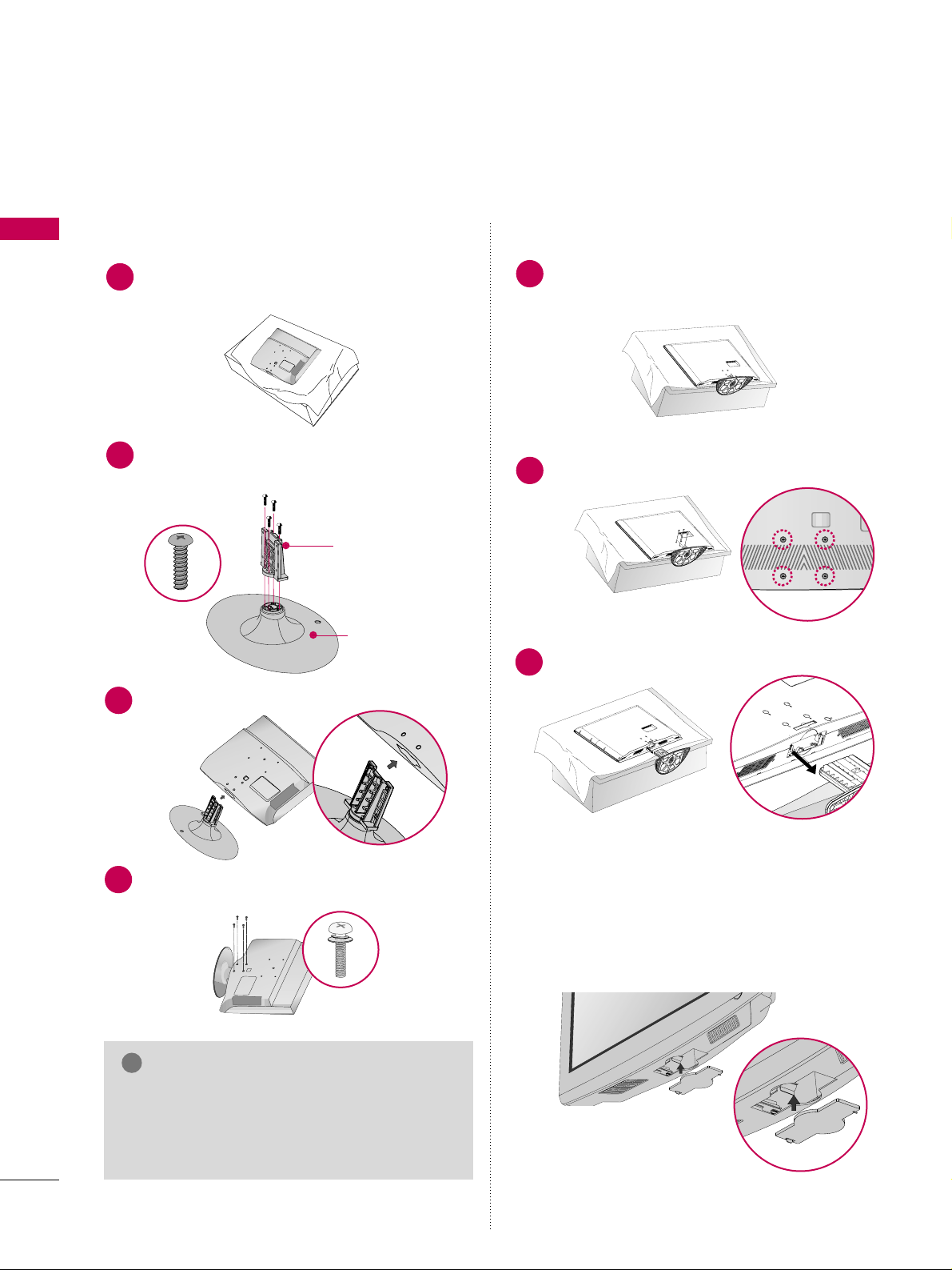
STAND INSTRUCTION
■
Image shown may differ from your TV.
Assemble the parts of the
SS TTAANNDD BBOODDYY
with
CCOOVVEERR BBAASSEE
of the TV.
2
Assemble the TV as shown.
3
Fix the 4 bolts securely using the holes in the
back of the TV.
4
SS TTAANNDD BBOO DDYY
CCOOVVEERR BBAASSEE
Carefully place the TV screen side down on a
cushioned surface to protect the screen from
damage.
1
INSTALLATION DETACHMENT
Carefully place the TV screen side down on a
cushioned surface to protect the screen from
damage.
1
Loose the bolts from TV.
2
Detach the stand from TV.
3
After removing the stand, install the included
pprrootteecctt iioonn ccoovveerr
over the hole for the stand.
Press the
PPRROOTTEECCTTIIOONN CCOOVVEE RR
into the TV
until you hear it click. And push the tab aside.
PROTECTION COVER
GG
When assembling the desk type stand, make sure
the bolt is fully tightened (If not tightened fully,
the TV can tilt forward after the product installation). Do not over tighten.
NOTE
!
PREPARATION
11
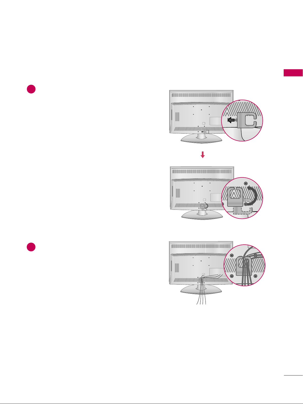
CABLE MANAGEMENT
■
Image shown may differ from your TV.
Align the hole with the tab on the
CCAABBLLEE
MMAANNAAGGEEMMEENNTT CCLLIIPP
.
Turn the
CCAABBLLEE MMAANNAAGGEEMMEENNTT CCLLIIPP
as
shown.
Note: This cable management clip can be bro-
ken by excessive pressure.
Connect the cables as necessary.
To connect additional equipment, see the
EXTERNAL EQUIPMENT SETUP section.
1
2
PREPARATION
12
DESKTOP PEDESTAL INSTALLATION
PREPARATION
GG
Ensure adequate ventilation by following the clearance recommendations.
GG
Do not mount near or above any type of heat source.
CAUTION
4 inches
4 inches
4 inches
4 inches
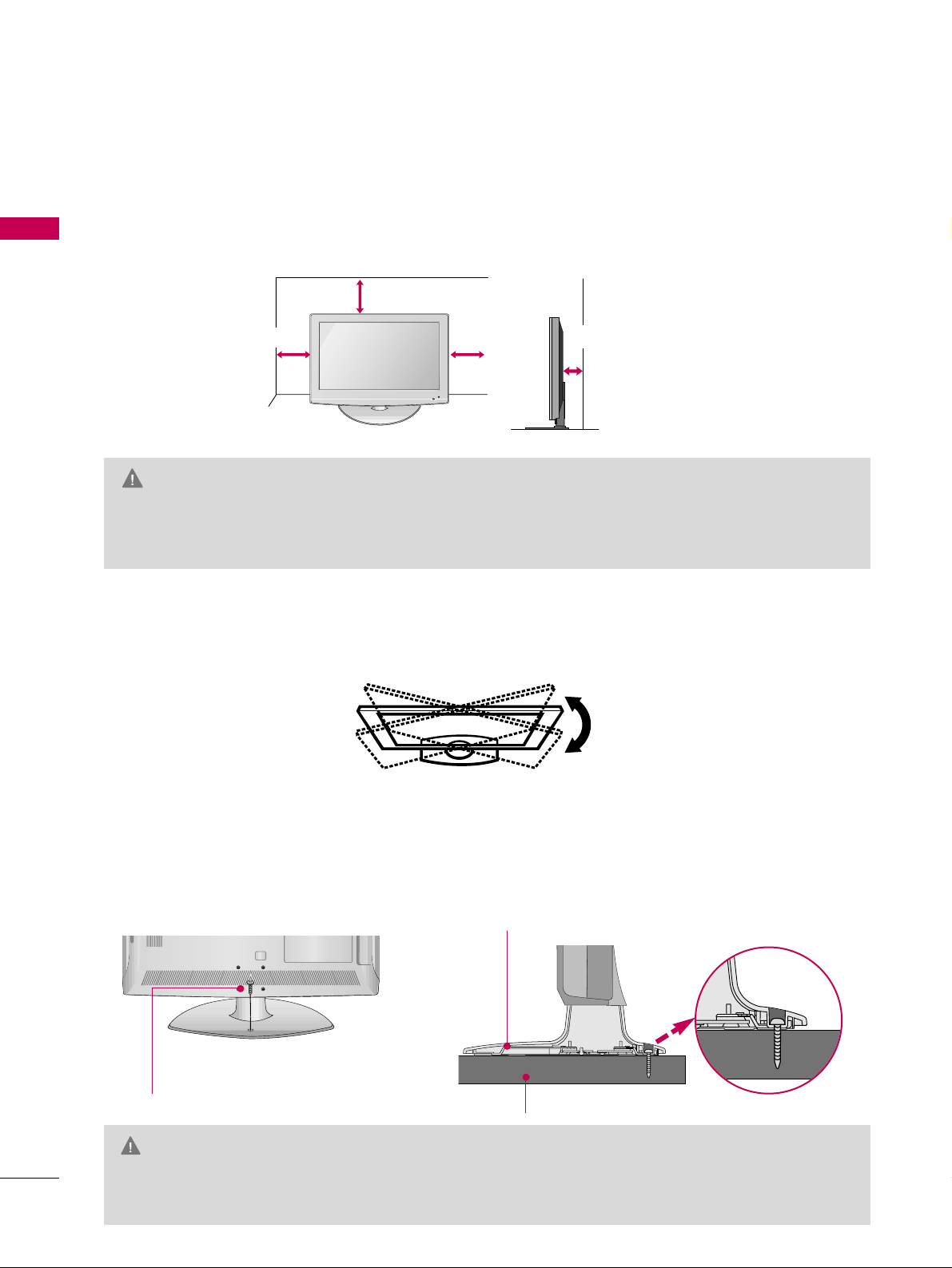
For proper ventilation, allow a clearance of 4 inches on all four sides from the wall.
■
Image shown may differ from your TV.
SWIVEL STAND
ATTACHING THE TV TO A DESK
After installing the TV, you can adjust the TV set manually to the left or right direction by 20 degrees to suit
your viewing position.
The TV should be attached to a desk so it cannot be pulled in a forward/backward direction, potentially causing injury or damaging the TV.
GG
To prevent TV from falling over, the TV should be securely attached to the floor/wall per installation
instructions. Tipping, shaking, or rocking the machine may cause injury.
WARNING
1-Screw
(provided as parts of the product)
Desk
Stand
PREPARATION
13
VESA WALL MOUNTING
Install your wall mount on a solid wall perpendicular to the floor. When attaching to other building materials, please
contact your nearest dealer.
If installed on a ceiling or slanted wall, it may fall and result in severe personal injury.
We recommend that you use an LG brand wall mount when mounting the TV to a wall.
LG recommends that wall mounting be performed by a qualified professional installer.
GG
Do not install your wall mount kit while your TV is turned on. It may result in personal injury due to electric
shock.
CAUTION
GG
Screw length needed depends on the wall mount
used. For further information, refer to the instructions included with the mount.
GG
Standard dimensions for wall mount kits are shown
in the table.
GG
When purchasing our wall mount kit, a detailed
installation manual and all parts necessary for
assembly are provided.
GG
Do not use screws longer then the standard dimension, as they may cause damage to the inside to
the TV.
GG
For wall mounts that do not comply with the VESA
standard screw specifications, the length of the
screws may differ depending on their specifications.
GG
Do not use screws that do not comply with the
VESA standard screw specifications.
Do not use fasten the screws too strongly, this may
damage the TV or cause the TV to a fall, leading to
personal injury. LG is not liable for these kinds of
accidents.
GG
LG is not liable for TV damage or personal injury
when a non-VESA or non specified wall mount is
used or the consumer fails to follow the TV installation instructions.
NOTE
!
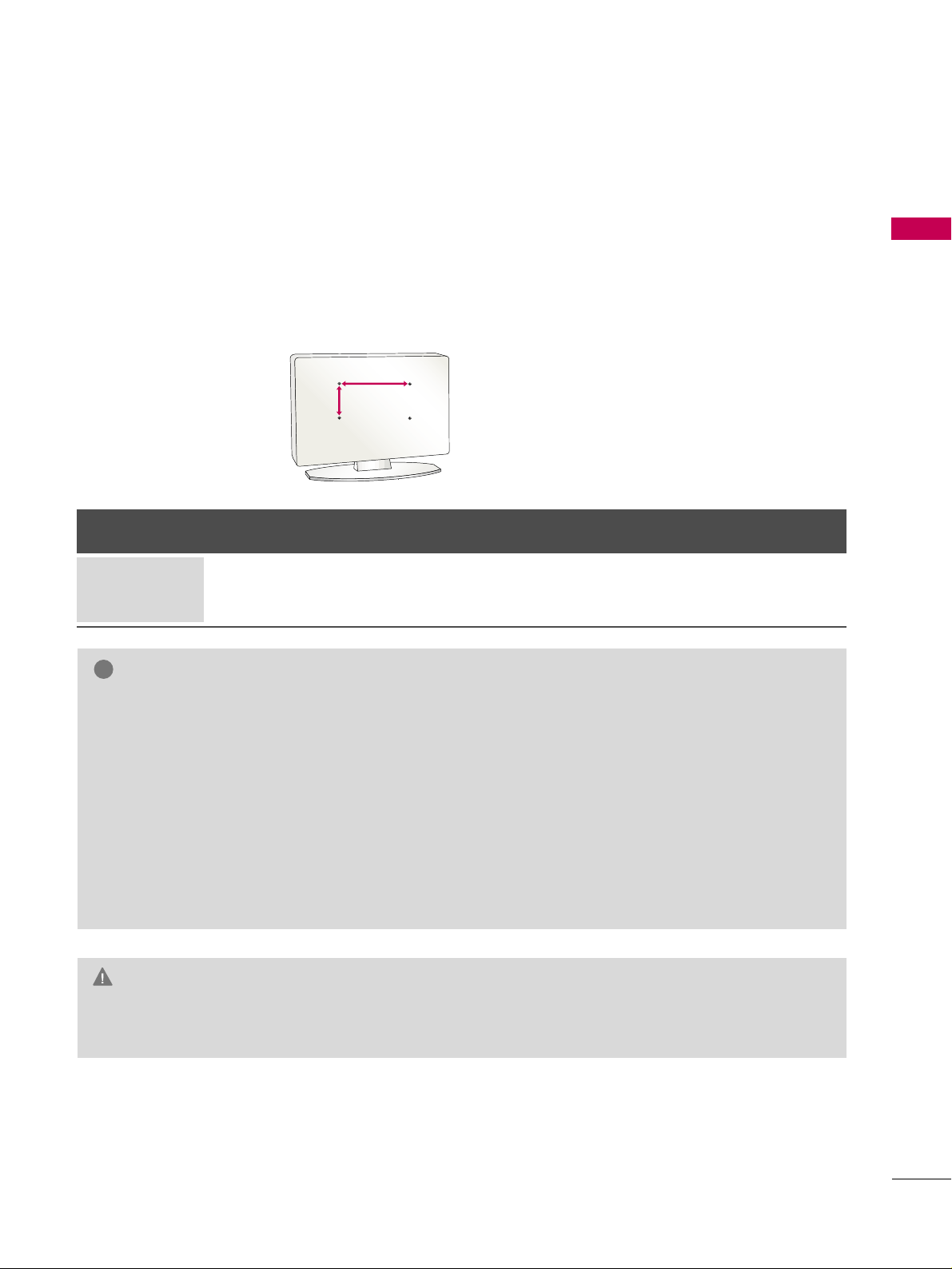
AA
BB
Product Model
VESA
(A *B)
Standard Screw Quantity
26LG40, 32LG40 200* 10 0 M 4 4
LCD TV
PREPARATION
14
SECURING THE TV TO THE WALL TO PREVENT FALLING WHEN THE TV IS USED ON A STAND
PREPARATION
We recommend that you set up the TV close to a wall so it cannot fall over if pushed backwards.
Additionally, we recommend that the TV be attached to a wall so it cannot be pulled in a forward direction,
potentially causing injury or damaging the product.
Caution: Please make sure that children don’t climb on or hang from the TV.
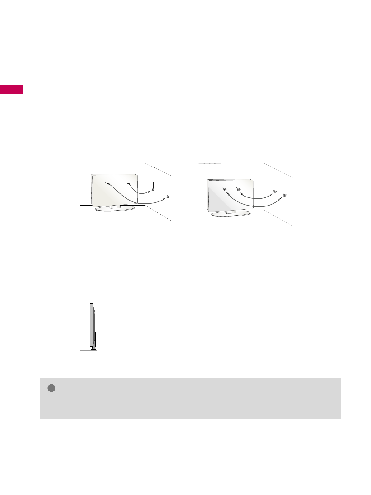
■
Insert the eye-bolts (or TV brackets and bolts) to tighten the product to the wall as shown in the picture.
*If your product has the bolts in the eye-bolts position before inserting the eye-bolts, loosen the bolts.
* Insert the eye-bolts or TV brackets/bolts and tighten them securely in the upper holes.
Secure the wall brackets with the bolts (sold separately) to the wall. Match the height of the bracket that is
mounted on the wall to the holes in the product.
Ensure the eye-bolts or brackets are tightened securely.
■
Use a sturdy rope (sold separately) to tie the product. It is safer to tie
the rope so it becomes horizontal between the wall and the product.
■
You should purchase necessary components to prevent TV from falling off of the stand.
■
Image shown may differ from your TV.
GG
Use a platform or cabinet strong enough and large enough to support the size and weight of the TV.
GG
To use the TV safely make sure that the height of the bracket on the wall and the one on the TV are the same.
NOTE
!
PREPARATION
15
ANTENNA OR CABLE CONNECTION
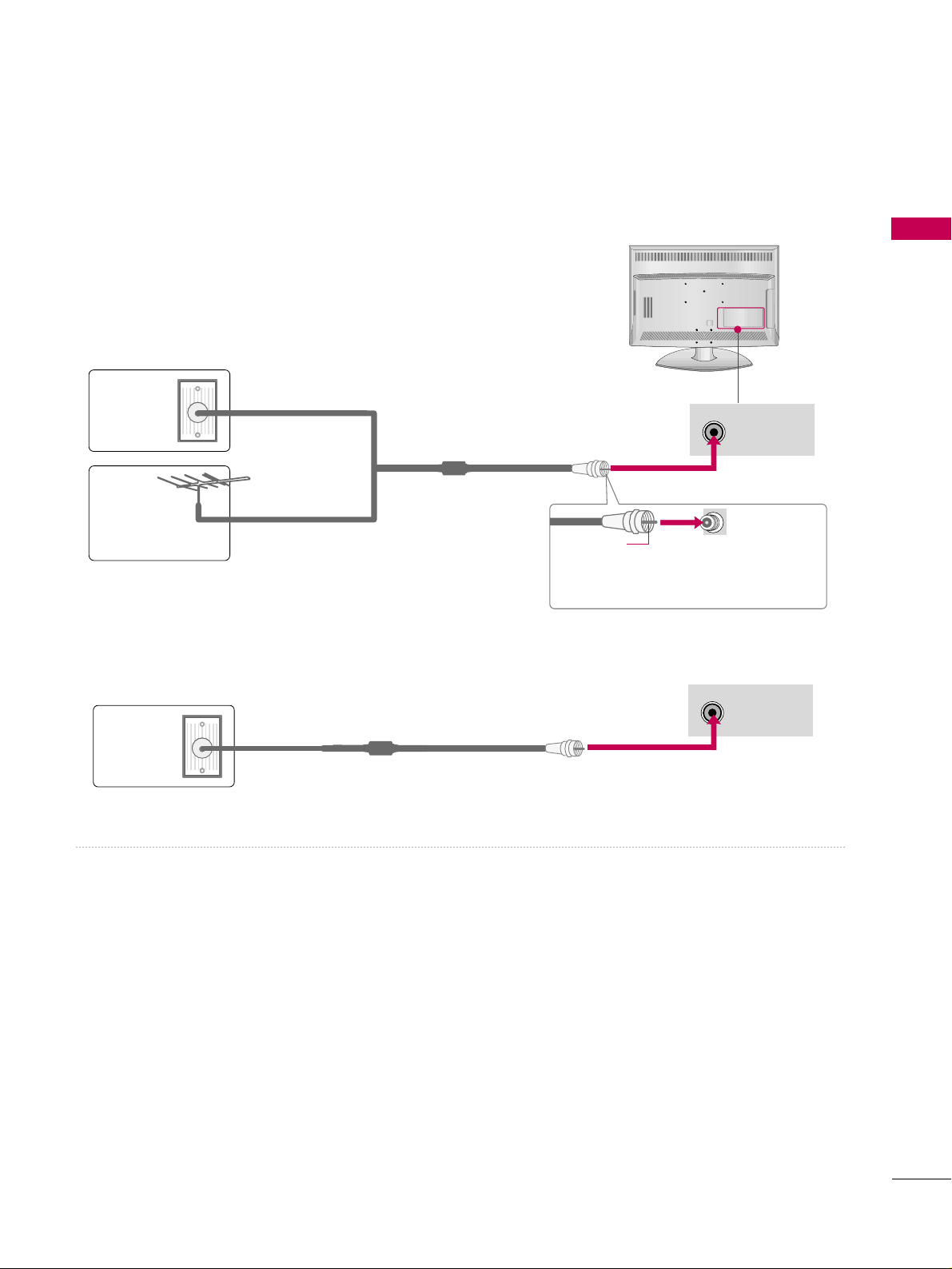
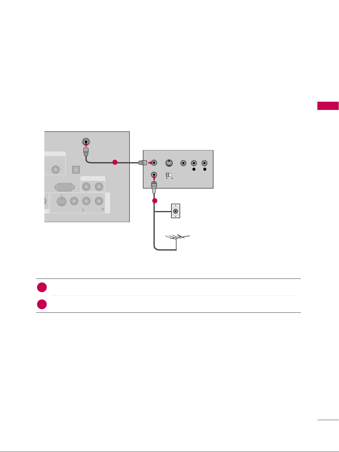
1. Antenna (Analog or Digital)
Wall Antenna Socket or Outdoor Antenna without a Cable Box
Connections.
For optimum picture quality, adjust the antenna direction if needed.
2. Cable
Wa ll
Antenna
Socket
Outdoor
Antenna
(VHF, UHF)
Cable TV
Wall Jack
Multi-family Dwellings/Apartments
(Connect to wall antenna socket)
RF Coaxial Wire (75 ohm)
RF Coaxial Wire (75 ohm)
Single-family Dwellings /Houses
(Connect to wall jack for outdoor antenna)
Be careful not to bend the copper wire
when connecting the antenna.
Copper Wire
■
To improve the picture quality in a poor signal area, please purchase a signal amplifier and install properly.
■
If the antenna needs to be split for two TV’s, install a 2-Way Signal Splitter.
■
If the antenna is not installed properly, contact your dealer for assistance.
ANTENNA/
CABLE IN
R
ANTENNA/
CABLE IN
R
R
■
To prevent damage do not connect to the power outlet until all connections are made between the devices.
EXTERNAL EQUIPMENT SETUP
16
EXTERNAL EQUIPMENT SETUP
HD RECEIVER SETUP
This TV can receive digital over-the-air or digital cable signals without an external digital set-top box. However, if
you do receive digital signals from a digital set-top box or other digital external device, refer to the figure as
shown below.
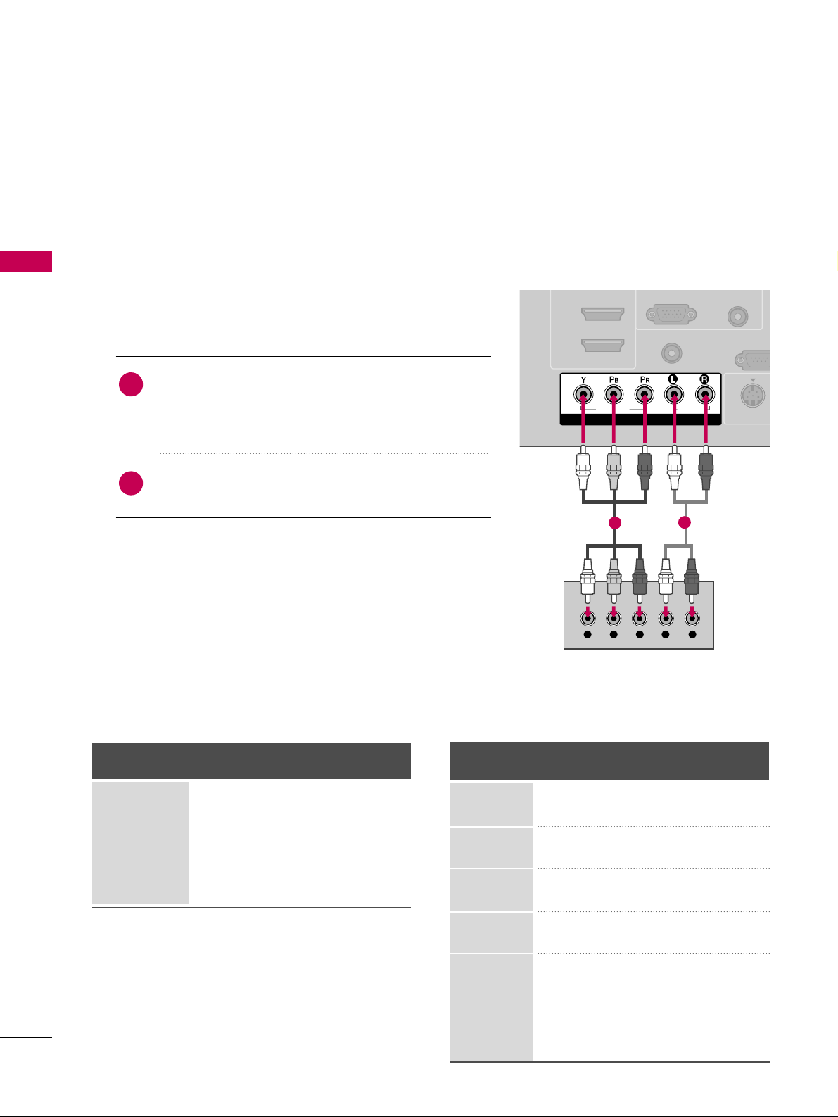
Component Connection
1. How to connect
Connect the video outputs (Y, P
B
, PR
)
of the digital set-
top box to the
CCOOMMPPOONNEENNTT II NN VVII DDEEOO
jacks on
the TV. Match the jack colors (Y = green, P
B
= blue, and
P
R
= red).
Connect the audio output of the digital set-top box to
the
CCOOMMPPOONNEENNTT IINN AAUUDDIIOO
jacks on the TV.
2
1
2. How to use
■
Turn on the digital set-top box.
(
Refer to the owner’s manual for the digital set-top box. operation
)
■
Select the
CCoommppoonneenntt
input source on the TV using the
IINNPPUU TT
button on the remote control.
■
To prevent the equipment damage, never plug in any power cords until you have finished connecting all equipment.
COMPONENT IN
AUDIO
(RGB/DVI)
RGB(PC)
REMOTE
CONTROL IN
RS-232C
(CONTROL & S
A
( )
S-VIDEO
2
1
VIDEO
AUDIO
( )
Y L RPB PR
1
2
Y, C
B/
PB
, CR/
PR
Horizontal Vertical
Frequency(KHz)Frequency(Hz
)
15.73 59.94
15.73 60.00
31.47 59.94
31.50 60.00
44.96 59.94
45.00 60.00
33.72 59.94
33.75 60.00
26.97 23.94
27.00 24.00
33.71 29.97
33.75 30.00
67.43 59.94
67.50 60.00
Resolution
720x480i
720x480p
1280x720p
1920x1080i
1920x1080p
Signal
480i
480p
720p
10 8 0 i
10 8 0 p
Component
Yes
Yes
Yes
Yes
Yes
HDMI
No
Yes
Yes
Yes
Yes
Supported Resolutions
EXTERNAL EQUIPMENT SETUP
17
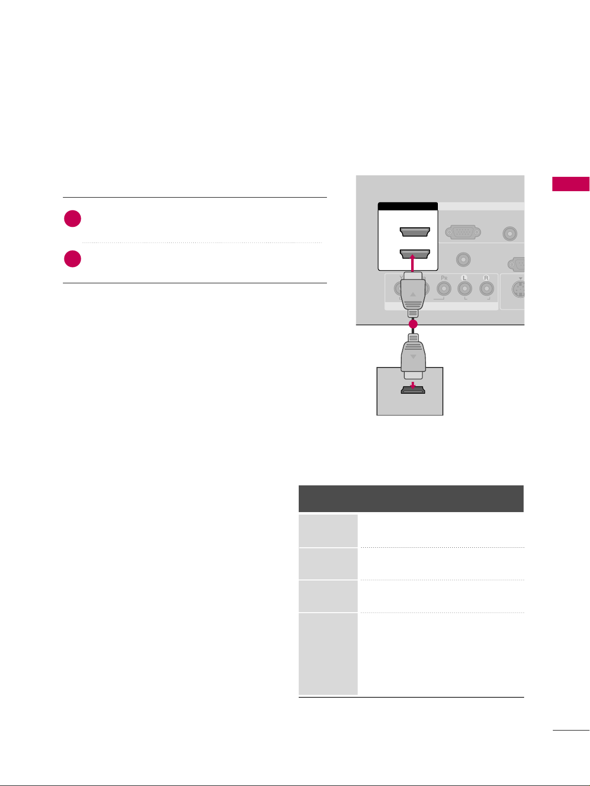
Connect the digital set-top box to
HHDDMMII //DDVVII IINN11
,
22
, or
33
jack on the TV.
No separate audio connection is necessary.
HDMI supports both audio and video.
1. How to connect
2. How to use
■
Turn on the digital set-top box.
(
Refer to the owner’s manual for the digital set-top box.
)
■
Select the
HHDDMMII11, HHDDMMII22
, or
HHDDMMII33
input source on the
TV using the
IINNPPUUTT
button on the remote control.
2
1
HDMI-DTV
Horizontal Vertical
Frequency(KHz)Frequency(Hz
)
31.47 59.94
31.50 60.00
44.96 59.94
45.00 60.00
33.72 59.94
33.75 60.00
26.97 23.976
27.00 24.00
33.71 29.97
33.75 30.00
67.432 59.939
67.50 60.00
Resolution
720x480p
1280x720p
1920x1080i
1920x1080p
HDMI Connection
COMPONENT IN
AUDIO
(RGB/DVI)
RGB(PC)
REMOTE
CONTROL IN
RS-23
(CONTROL
VIDEO
AUDIO
( )
S-VID
RGB IN
2
1
HDMI/DVI IN
HDMI-DTV OUTPUT
1
EXTERNAL EQUIPMENT SETUP
18
EXTERNAL EQUIPMENT SETUP
DVI to HDMI Connection
( )
( )
COMPONENT IN
AUDIO
(RGB/DVI)
RGB(PC)
REMOTE
CONTROL IN
RS-232C IN
(CONTROL & SERVICE)
VIDEO
AUDIO
DIGITAL
AUDIO OU
OPTICA
VIDEO
( )
S-VIDEO
RGB IN
2
1
HDMI/DVI IN
L R
DVI-DTV OUTPUT
1
2
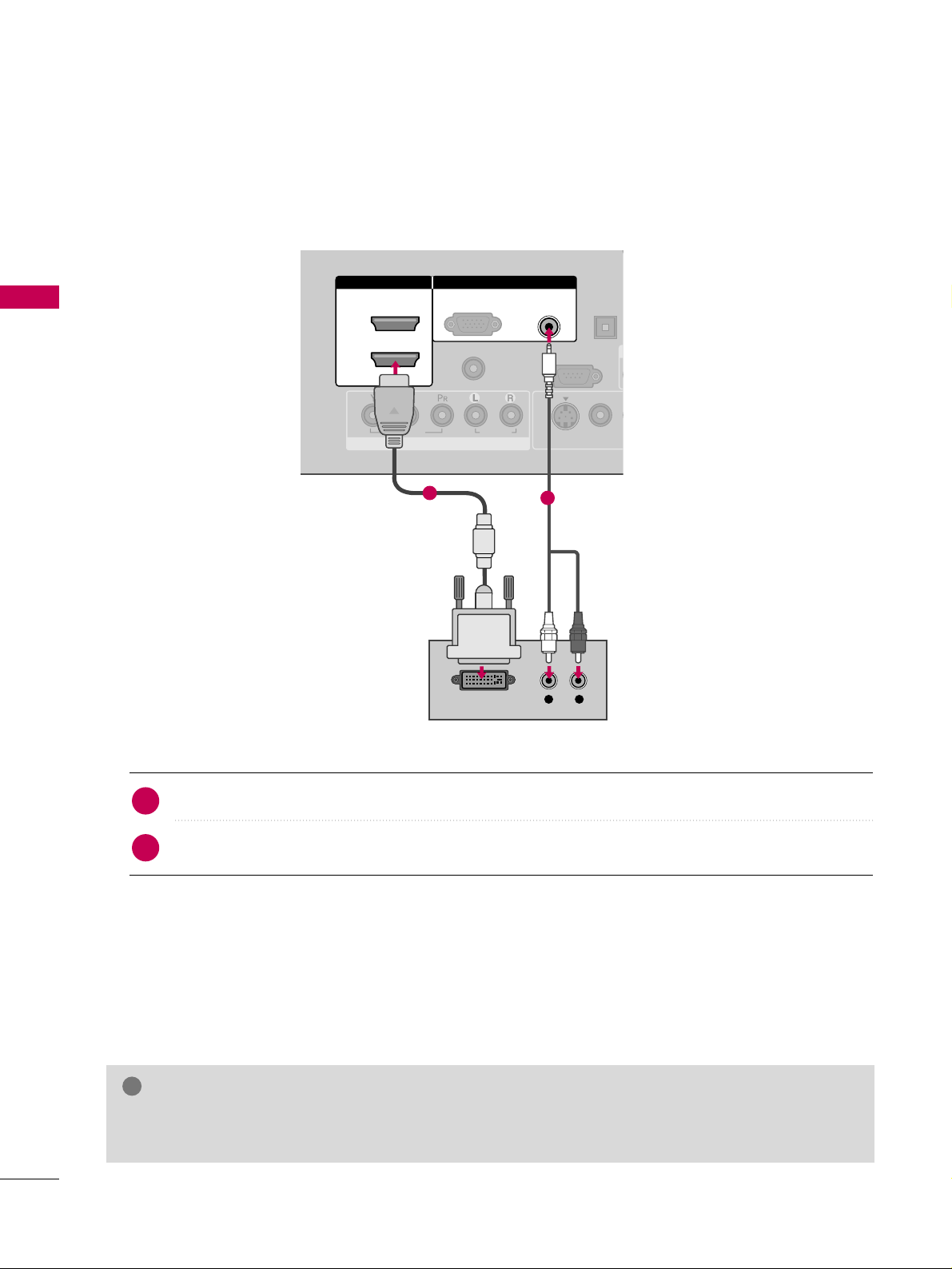
Connect the DVI output of the digital set-top box to the
HHDDMMII//DDVVII IINN11, 22
, or 33jack on the TV.
Connect the PC audio output to the
AAUUDDIIOO ((RRGGBB//DDVVII))
jack on the TV.
1. How to connect
2. How to use
■
Turn on the digital set-top box.
(
Refer to the owner’s manual for the digital set-top box.
)
■
Select the
HHDDMMII 11, HHDDMMII 22 orHHDDMMII 33
input source on the TV using the
IINNPPUUTT
button on the remote
control.
2
1
GG
A DVI to HDMI cable or adapter is required for this connection. DVI doesn't support audio, so a separate
audio connection is necessary.
NOTE
!
EXTERNAL EQUIPMENT SETUP
19
DVD SETUP
Component Connection
Component Input ports
To get better picture quality, connect a DVD player to the component input ports as shown below.
Component ports on the TV
YPBP
R
Video output ports
on DVD player
Y
Y
Y
Y
P
B
B-Y
Cb
Pb
P
R
R-Y
Cr
Pr
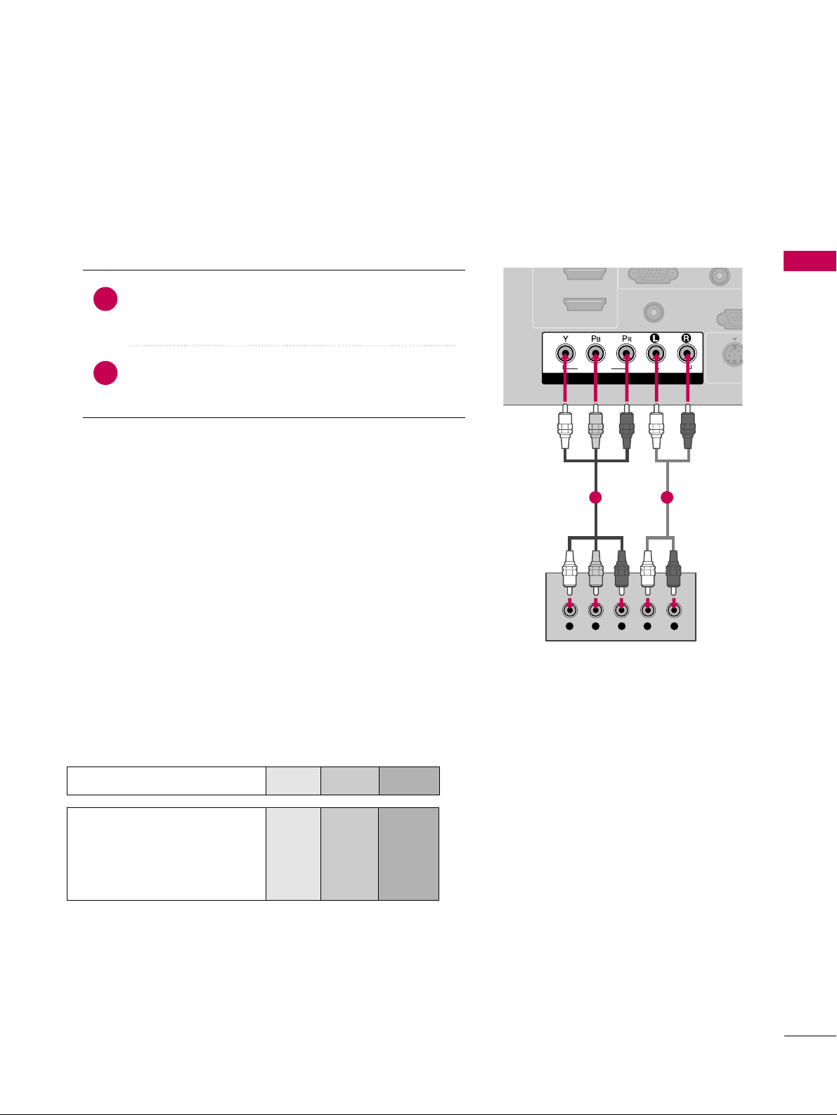
Connect the video outputs (Y, P
B, P
R
)
of the DVD to the
CCOOMM PPOONNEENNTT IINN VVIIDDEEOO
jacks on the TV. Match the
jack colors (Y = green, P
B = blue, and P
R = red
)
.
Connect the audio outputs of the DVD to the
CCOO MMPPOO--
NNEE NNTT IINN AAUUDDIIOO
jacks on the TV.
1. How to connect
2. How to use
■
Turn on the DVD player, insert a DVD.
■
Select
CCoommppoonneenntt
input source by using the
IINNPPUU TT
button on the remote control.
■
Refer to the DVD player's manual for operating instructions.
2
1
COMPONENT IN
REMOTE
CONTROL IN
RS-23
(CONTROL &
( )
S-VIDE
2
1
VIDEO
AUDIO
Y L RPB PR
1 2
EXTERNAL EQUIPMENT SETUP
20
EXTERNAL EQUIPMENT SETUP
S-Video Connection
( )
AUDIO
(RGB/DVI)
REMOTE
CONTROL IN
ANTENNA/
CABLE IN
RS-232C IN
(CONTROL & SERVICE)
AUDIO
DIGITAL
AUDIO OUT
OPTICAL
AUDIO OUT
VIDEO
MONO
( )
AUDIO
S-VIDEO
RGB IN
AV IN 1
S-VIDEO
L R
S-VIDEO
AUDIO
1
2
HDMI Connection
COMPONENT IN
AUDIO
(RGB/DVI)
RGB(PC)
REMOTE
CONTROL IN
RS-23
(CONTROL
VIDEO
AUDIO
( )
S-VID
RGB IN
2
1
HDMI/DVI IN
HDMI-DVD OUTPUT
1
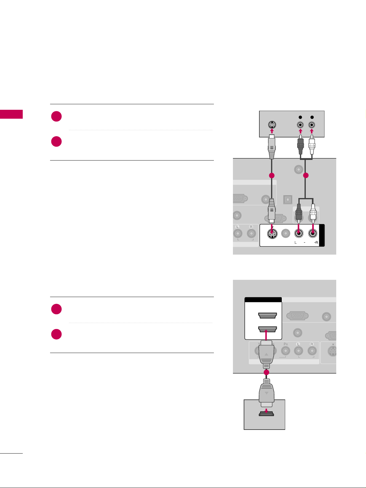
1. How to connect
Connect the S-VIDEO output of the DVD to the
SS --
VVIIDDEEOO
input on the TV.
Connect the audio outputs of the DVD to the
AAUUDDIIOO
input jacks on the TV.
2
1
2. How to use
■
Turn on the DVD player, insert a DVD.
■
Select the
AAVV11
input source on the TV using the
IINNPPUU TT
button on the remote control.
■
Refer to the DVD player's manual for operating instructions.
1. How to connect
Connect the HDMI output of the DVD to the
HHDDMMII//DDVVII IINN 11, 22
, or
33
jack on the TV.
No separated audio connection is necessary.
HDMI supports both audio and video.
2
1
2. How to use
■
Select the
HHDDMMII 11, 22
, or 33input source on the TV using
the
IINNPPUU TT
button on the remote control.
■
Refer to the DVD player's manual for operating instructions.
EXTERNAL EQUIPMENT SETUP
21
VCR SETUP
Antenna Connection
■
To avoid picture noise (interference), leave an adequate distance between the VCR and TV.
■
If the 4:3 picture format is used; the fixed images on the sides of the screen may remain visible on the screen.
This phenomenon is common to all TVs and is not covered by warranty.
Connect the RF antenna out socket of the VCR to the
AANN TTEENNNNAA//CCAABBLLEE IINN
socket on the TV.
Connect the antenna cable to the RF antenna in socket of the VCR.
1. How to connect
■
Set VCR output switch to 3 or 4 and then tune TV to the same channel number.
■
Insert a video tape into the VCR and press PLAY on the VCR. (Refer to the VCR owner’s manual.
)
2. How to use
2
1
AUDIO
(RGB/DVI)
ANTENNA/
CABLE IN
RS-232C IN
(CONTROL & SERVICE)
DIGITAL
AUDIO OUT
OPTICAL
AUDIO OUT
AV IN 1
VIDEO
MONO
( )
AUDIO
S-VIDEO
L R
S-VIDEO VIDEO
OUTPUT
SWITCH
ANT IN
ANT OUT
( )
Wall Jack
Antenna
1
2
EXTERNAL EQUIPMENT SETUP
22
EXTERNAL EQUIPMENT SETUP
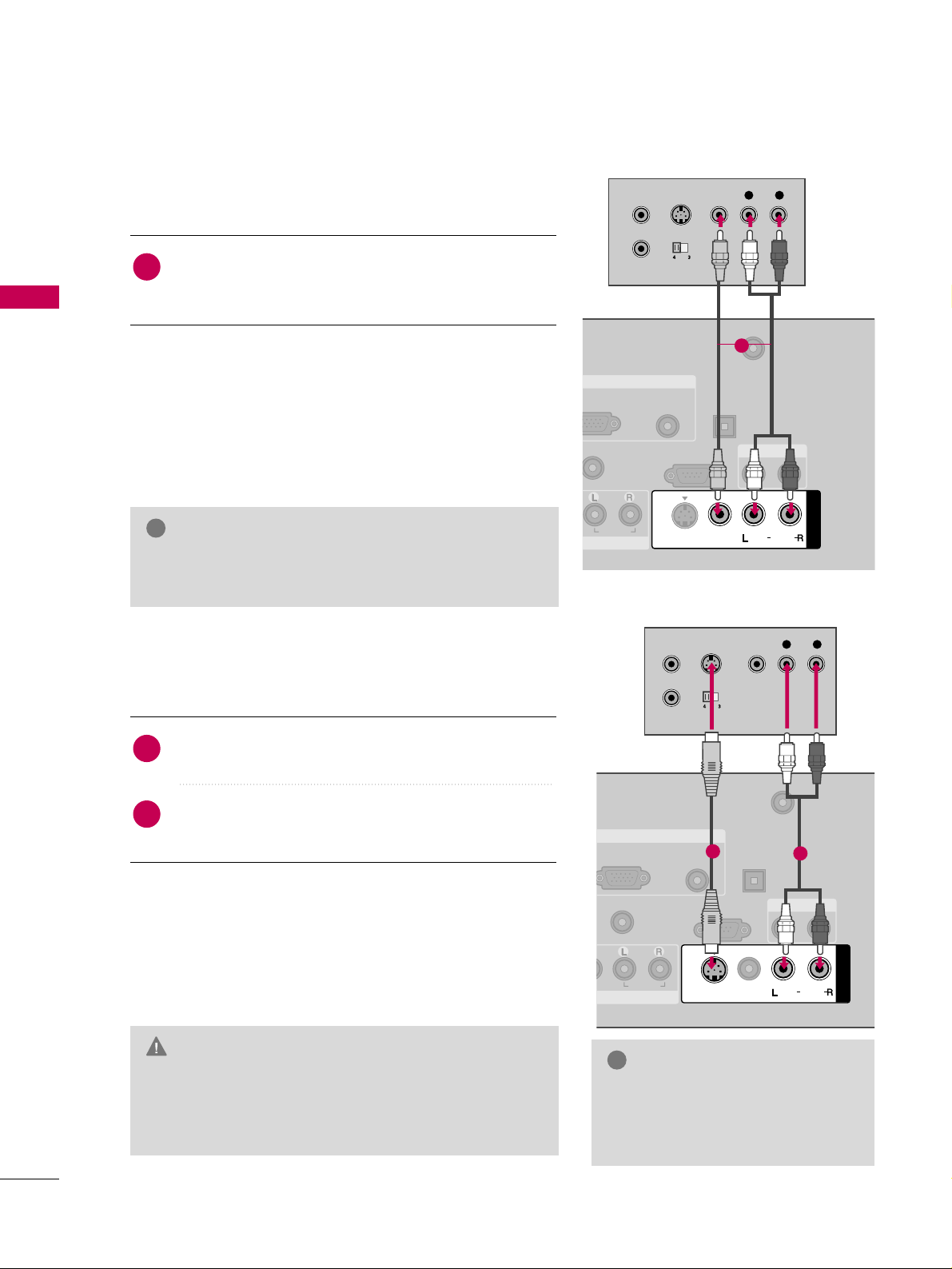
Composite (RCA) Connection
GG
If you have a mono VCR, connect the audio cable from
the VCR to the
AAUUDDIIOO LL // MMOONNOO
jack of the TV.
NOTE
!
GG
Do not connect to both Video and S-Video at the same
time. In the event that you connect both Video and the
S-Video cables, only the S-Video will work.
CAUTION
GG
The picture quality is improved:
compared to normal composite
(RCA cable) input.
NOTE
!
AUDIO
(RGB/DVI)
REMOTE
CONTROL IN
ANTENNA/
CABLE IN
RS-232C IN
(CONTROL & SERVICE)
AUDIO
DIGITAL
AUDIO OUT
OPTICAL
AUDIO OUT
MONO
( )
AUDIO
S-VIDEO
RGB IN
AV IN 1
VIDEO
L R
S-VIDEO VIDEO
OUTPUT
SWITCH
ANT IN
ANT OUT
1
1. How to connect
Connect the
AAUUDDIIOO/VVIIDDEEOO
jacks between TV and
VCR. Match the jack colors (Video = yellow, Audio Left
= white, and Audio Right = red)
1
2. How to use
■
Insert a video tape into the VCR and press PLAY on the
VCR. (Refer to the VCR owner’s manual.
)
■
Select the
AAVV11
input source on the TV using the
IINNPPUU TT
button on the remote control.
■
If connected to
AAVV IINN22
, select
AAVV22
input source on the TV.
S-Video Connection
( )
AUDIO
(RGB/DVI)
RGB(PC)
REMOTE
CONTROL IN
ANTENNA/
CABLE IN
RS-232C IN
(CONTROL & SERVICE)
AUDIO
DIGITAL
AUDIO OUT
OPTICAL
AUDIO OUT
VIDEO
MONO
( )
AUDIO
S-VIDEO
RGB IN
AV IN 1
L R
S-VIDEO VIDEO
OUTPUT
SWITCH
ANT IN
ANT OUT
( )
1
2
1. How to connect
Connect the S-VIDEO output of the VCR to the
SS --
VVIIDDEEOO
input on the TV.
Connect the audio outputs of the VCR to the
AAUUDDIIOO
input jacks on the TV.
2
1
2. How to use
■
Insert a video tape into the VCR and press PLAY on the
VCR. (Refer to the VCR owner’s manual.
)
■
Select the
AAVV11
input source on the TV using the
IINNPPUU TT
button on the remote control.
EXTERNAL EQUIPMENT SETUP
23
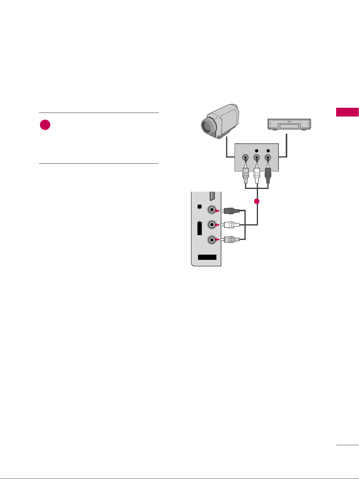
OTHER A/V SOURCE SETUP
AV IN 2
L/ MONO
R
AUDIO
VIDEO
HDMI IN 3 USB IN
L R
VIDEO
Camcorder
Video Game Set
Connect the
AAUUDDIIOO/VVIIDDEEOO
jacks
between TV and external equipment.
Match the jack colors
.
(
Video = yellow, Audio Left = white, and
Audio Right = red
)
1. How to connect
2. How to use
■
Select the
AAVV22
input source on the TV using
the
IINNPPUU TT
button on the remote control.
■
If connected to
AAVV IINN11
input, select the
AAVV11
input source on the TV.
■
Operate the corresponding external equipment.
1
1
EXTERNAL EQUIPMENT SETUP
24
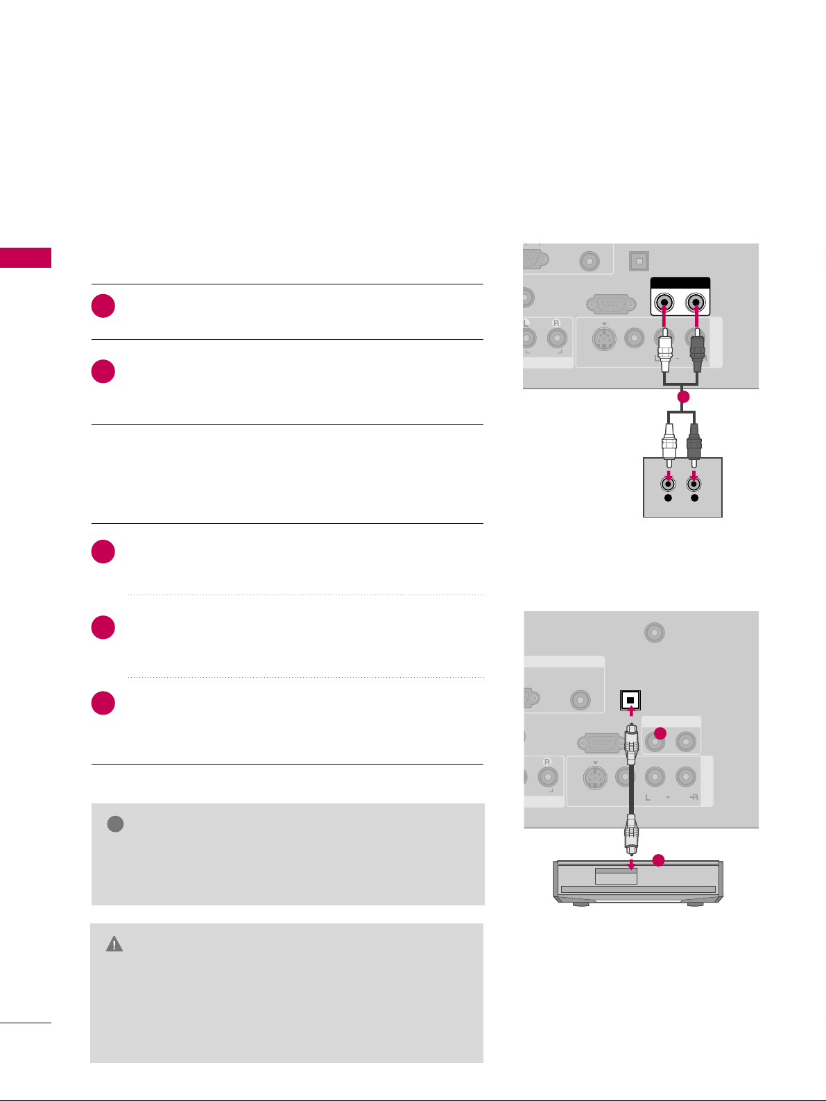
AUDIO OUT CONNECTION
EXTERNAL EQUIPMENT SETUP
Send the TV’s audio to external audio equipment via the Audio Output port.
(RGB/DVI)
(C)
REMOTE
CONTROL IN
RS-232C IN
(CONTROL & SERVICE)
AUDIO
OPTICAL
AUDIO OUT
AV IN 1
VIDEO
MONO
( )
AUDIO
S-VIDEO
L R
AUDIO
1
AUDIO
(RGB/DVI)
REMOTE
CONTROL IN
ANTENNA/
CABLE IN
RS-232C IN
(CONTROL & SERVICE)
DIGITAL
AUDIO OUT
OPTICAL
AUDIO OUT
AV IN 1
VIDEO
MONO
( )
AUDIO
S-VIDEO
GB IN
( )
1
2
GG
When connecting with external audio equipments, such as
amplifiers or speakers, you can turn the TV speakers off in
the menu. (
GG
pp..7799
)
NOTE
!
G
Do not look into the optical output port. Looking at the
laser beam may damage your vision.
GG
Composite audio out (the red and white jacks) only works
with composite inputs. Use optical audio output for any
type of DTV signal.
CAUTION
Connect one end of the optical cable to the TV’s
OOPPTT II--
CCAALL
port of
DDIIGGIITTAALL AAUUDDIIOO OOUUTT
.
Connect the other end of the optical cable to the digital
audio input on the audio equipment.
Set the “TV Speaker option - Off” in the AUDIO menu. (
GG
pp..7799
). See the external audio equipment instruction manu-
al for operation.
1. How to connect
2
3
1
Connect audio outputs to the TV’s
AAUUDDIIOO OOUUTT
jacks.
Set the “TV Speaker option - Off” in the AUDIO menu.
(
GG
pp..7799
). See the external audio equipment instruction
manual for operation.
1. How to connect
2
1
Analog
Digital
EXTERNAL EQUIPMENT SETUP
25
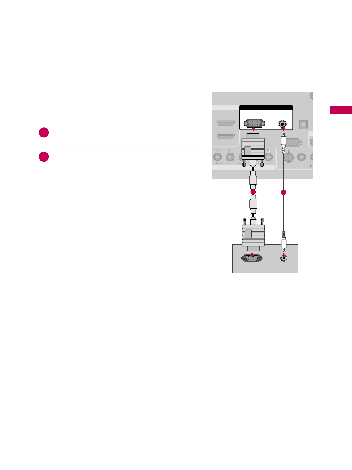
PC SETUP
This TV provides Plug and Play capability, no display driver is needed.
VGA (D-Sub 15 pin) Connection
COMPONENT IN
REMOTE
CONTROL IN
VIDEO
AUDIO
DIGITAL
AUDIO OUT
OPTICAL
A
VIDEO
M
( )
S-VIDEO
RGB IN
RS-232C IN
(CONTROL & SERVICE)
AUDIO
(RGB/DVI)
RGB(PC)
RGB OUTPUT
AUDIO
1
2
1. How to connect
Connect the VGA output of the PC to the
RRGGBB
((
PPCC
))
jack on the TV.
Connect the PC audio output to the
AAUUDD IIOO
((
RRGGBB//DDVVII
))
jack on the TV.
2
1
2. How to use
■
Turn on the PC and the TV.
■
Select the
RRGGBB--PPCC
input source on the TV using the
IINNPPUU TT
button on the remote control.
EXTERNAL EQUIPMENT SETUP
26
EXTERNAL EQUIPMENT SETUP
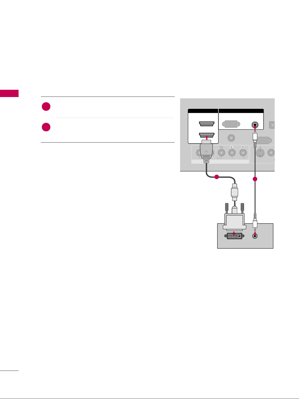
1. How to connect
Connect the DVI output of the PC to the
HHDDMMII//DDVVII
IINN11, 22
, or
33
jack on the TV.
Connect the PC audio output to the
AAUU DD II OO
((RRGGBB//DDVVII))
jack on the TV.
2
1
2. How to use
■
Turn on the PC and the TV.
■
Select the
HHDDMMII 11, HHDDMMII 22 orHHDDMMII 33
input source on the
TV using the
IINNPPUU TT
button on the remote control.
DVI to HDMI Connection
( )
COMPONENT IN
AUDIO
(RGB/DVI)
RGB(PC)
REMOTE
CONTROL IN
RS-232C IN
(CONTROL & SERVICE)
VIDEO
AUDIO
DIGIT
AUDIO
OPTIC
VIDEO
( )
S-VIDEO
RGB IN
2
1
HDMI/DVI IN
DVI-PC OUTPUT
AUDIO
1
2
EXTERNAL EQUIPMENT SETUP
27
GG
To get the the best picture quality, adjust the PC
graphics card to 1360x768.
GG
Depending on the graphics card, DOS mode may
not work if a HDMI to DVI Cable is in use.
GG
In PC mode, there may be noise associated with
the resolution, vertical pattern, contrast or brightness. If noise is present, run Auto Config. in the
Screen (RGB-PC) menu. You may also try changing
the PC output to another resolution, change the
refresh rate to another rate or adjust the bright-
ness and contrast on the PICTURE menu until the
picture is clear.
GG
Avoid keeping a fixed image on the screen for a
long period of time. The fixed image may become
permanently imprinted on the screen.
GG
The synchronization input form for Horizontal and
Vertical frequencies is separate.
NOTES
!
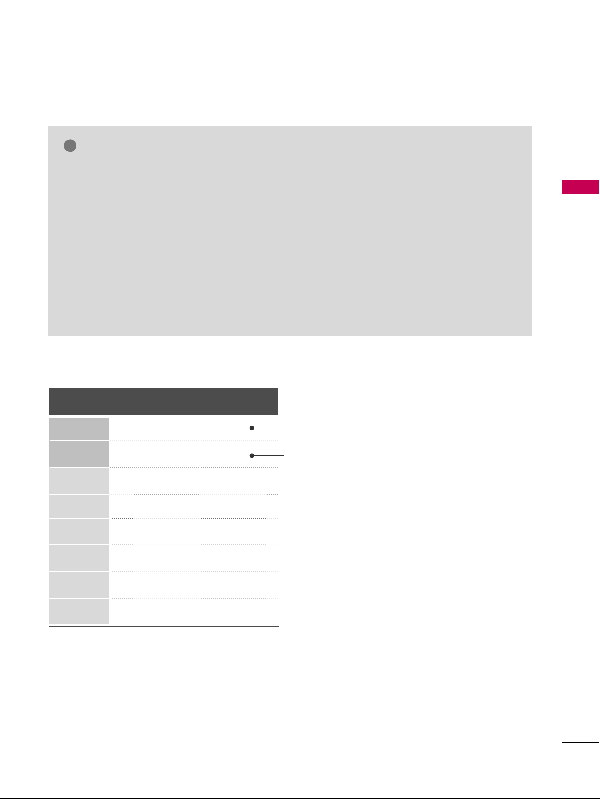
Supported Display Specifications (RGB-PC, HDMI-PC)
Horizontal Vertical
Frequency(KHz)Frequency(Hz
)
31.469 70.08
31.469 70.08
31.469 59.94
37.879 60.31
48.363 60.00
47.776 59.87
47.720 59.799
47.130 59.65
Resolution
720x400
1360x768
640x350
640x480
800x600
1024x768
1280x768
1366x768
* Only RGB-PC mode
EXTERNAL EQUIPMENT SETUP
28
EXTERNAL EQUIPMENT SETUP
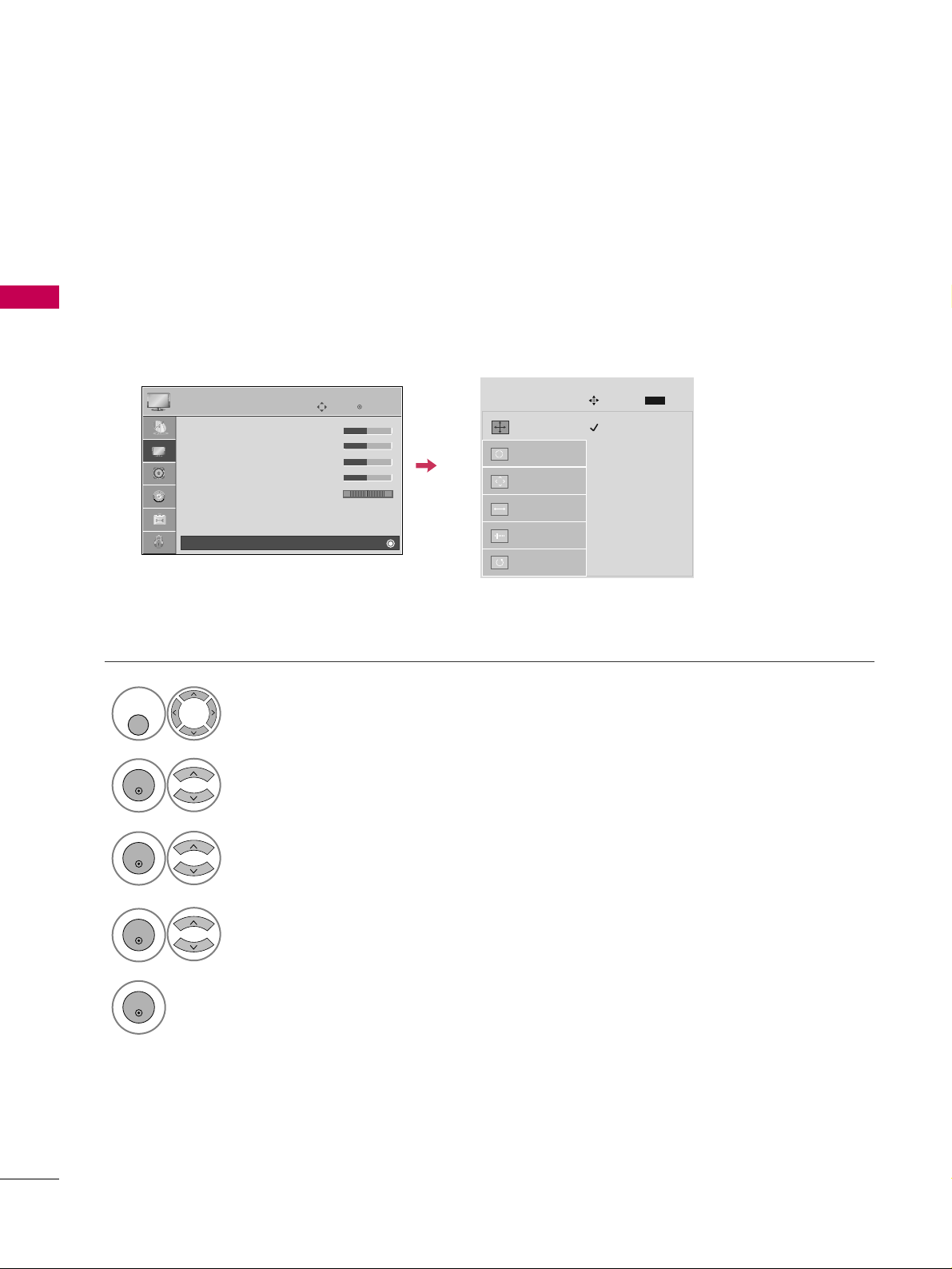
Screen Setup for PC mode
Selecting Resolution
You can choose the resolution in RGB-PC mode.
The
PPoossiittiioonn, PPhhaassee
, and
SSiizzee
can also be adjusted.
Select
PPIICCTTUURREE
.
Select
SS cc rreeeenn ((RRGGBB--PPCC))
.
Select
RReessoolluuttiioo nn
.
Select the desired resolution.
1024 x 768
1280 x 768
1360 x 768
1366 x 768
Auto config.
Resolution
G
Position
Size
Phase
Reset
SCREEN
Move
Prev.
MENU
1
MENU/
SET UP
3
4
2
ENTER
ENTER
ENTER
5
ENTER
Enter
Move
PICTURE
• Contrast 50
• Brightness 50
• Sharpness 50
• Color 50
• Tint 0
• Advanced Control
• Reset
Screen (RGB-PC)
RG
E
 Loading...