

LG 26LG3RC Owner’s Manual

LCD TV
OWNER’S MANUAL
LCD TV MODELS
26LG3
***
32LG3
***
37LG3
***
42LG3
***
47LG3
***
Please read this manual carefully before operating your set.
Retain it for future reference.
Record model number and serial number of the set.
Refer to the label on the back cover and quote this
information.
To your dealer when requiring service.
ENGLISH
PP//NNOO:: MMFFLL4411441100111100 ((00881100--RREEVV0022))
PPrriinntteedd iinn KKoorreeaa

1
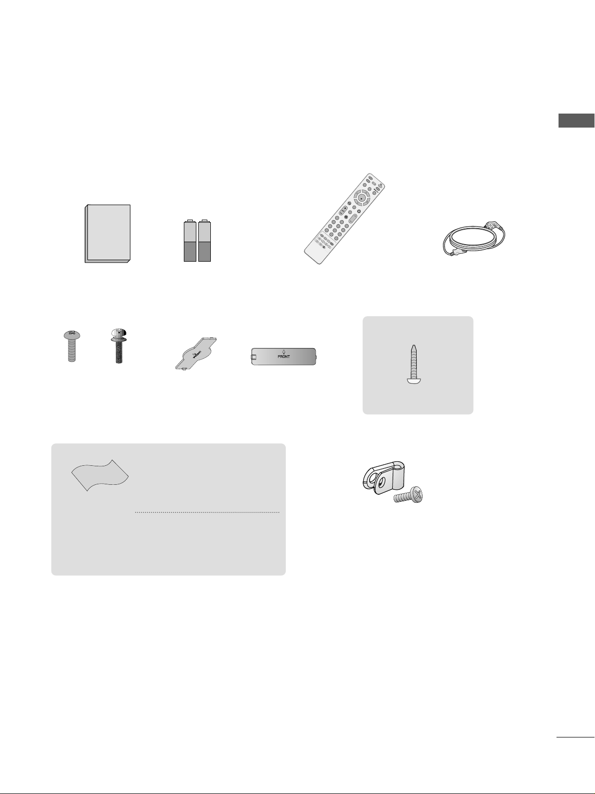
ACCESSORIES
Ensure that the following accessories are included with your TV. If an accessory is missing, please contact the
dealer where you purchased the product.
Owner's
Manual
Owner’s Manual Batteries
M
U
T
E
P
I
P
A
V
M
O
D
E
FAV
TV
IN
P
U
T
STB
P
O
W
E
R
Q. M
EN
U
M
E
N
U
O
K
123
456
78
0
9
LIST
Q
.VIE
W
DVD
T
I
M
E
S
I
Z
E
U
P
D
A
T
E
REVEAL
I
N
D
E
X
H
O
L
D
T
E
X
T
R
E
T
U
R
N
P
Remote Control Power Cord
Polishing Cloth
Polishing cloth for use
on the screen
This feature is not
available
for all models.
*
Lightly wipe any stains or
fingerprints on the surface
of the TV with the polishing
cloth.
Do not use excessive force.
This may cause scratching or
discolouration.
Bolts for stand assembly
(Refer to p.6)
(Only 26/32/37/42LG3
***
)
x 4 x 4
((OOnn llyy
22 66//3322 // 3377//4422LLGG33
******
))
Screw for stand fixing
(Refer to P. 9)
ACCESSORIES
protection cover
or
Protective Bracket and
Bolt for Power Cord
(Refer to P.8)
PICTURE CONTROL
Watching PIP(Picture-in-Picture) .............................47
Picture Size (Aspect Ratio)Control.........................48
Preset Picture Settings
- Picture Mode-Preset............................................50
- Auto Colour Tone Control(Cool/Medium/Warm)
51
Manual Picture Adjustment
- Picture Mode-User Option................................52
- Colour Tone - User Option...............................53
-
Picture Improvement Technology
...................54
Advanced - Gamma......................................................55
Advanced - Film Mode ................................................56
Advanced - Black(Darkness) Level...........................57
Advanced - Eye Care ...................................................58
Picture Reset..................................................................59
Power Indicator .............................................................60
Factory Reset.................................................................61
WATCHING TV /PROGRAMME CONTROL
Remote Control Key Functions..................................30
Turning on the TV ....................................................... 32
Programme Selection ................................................. 32
Volume Adjustment......................................................32
Quick Menu................................................................... 33
On Screen Menus Selection and Adjustment ......34
PICTURE CONTROL
WATCHING TV / PROGRAMME CONTROL
AACCCCEESSSSOORRIIEESS
.....................................................1
2
CONTENTS
CONTENTS
PREPARATION
Front Panel Controls................................................... 4
Back Panel Information .............................................. 5
Stand Installation ........................................................ 6
Please set it up carefully so the product
does not fall over.
. . . . . . . . . . . . . . . . . . . . . . . . . .7
Back Cover for Wire Arrangement........................... 8
Swivel Stand ................................................................. 9
Desktop Pedestal Installation................................. 10
Wall Mount: Horizontal installation....................... 11
Not using the desk-type stand................................11
Antenna Connection ................................................ 12
PREPARATION
EXTERNAL EQUIPMENT SETUP
HD Receiver Setup .......................................................13
DVD Setup..................................................................... 16
VCR Setup ..................................................................... 19
Other A/V Source Setup .......................................... 22
PC Setup.........................................................................23
- Screen Setup for PC Mode................................26
Auto Programme Tuning............................................ 35
Manual Programme Tuning ....................................... 36
Fine Tuning .....................................................................37
Assigning a Station Name ..........................................38
Booster............................................................................39
Programme Edit ........................................................... 40
Favourite Programme .................................................. 41
Selecting the Programme List .................................. 42
.................................................................. 43
Key lock.......................................................................... 45
AV Mode.........................................................................46

SOUND & LANGUAGE CONTROL
Auto Volume Leveler....................................................62
Preset Sound Settings - Sound Mode ....................63
Sound Setting Adjustment - User Mode ...............64
Balance............................................................................65
TV Speakers On/Off Setup .......................................66
I/II
- Stereo/Dual Reception....................................... 67
- NICAM Reception ....................................................... 68
- Speaker Sound Output Selection.................... 68
On-Screen Menu Language Selection
...................... 69
3
CONTENTS
APPENDIX
Troubleshooting............................................................77
Maintenance .................................................................79
Product Specifications................................................80
Programming the Remote Control ......................... 81
IR Codes ....................................................................... 83
External Control Through RS-232C ..................... 85
TIME SETTING
Clock Setup......................................................................70
Auto On/Off Timer Setting .........................................71
Sleep Timer Setting........................................................72
Auto Shut-off Setting...................................................73
TELETEXT
Switch On/Off ..............................................................74
SIMPLE Text....................................................................74
TOP Text .........................................................................75
FASTEXT .........................................................................75
Special Teletext Functions..........................................76
4
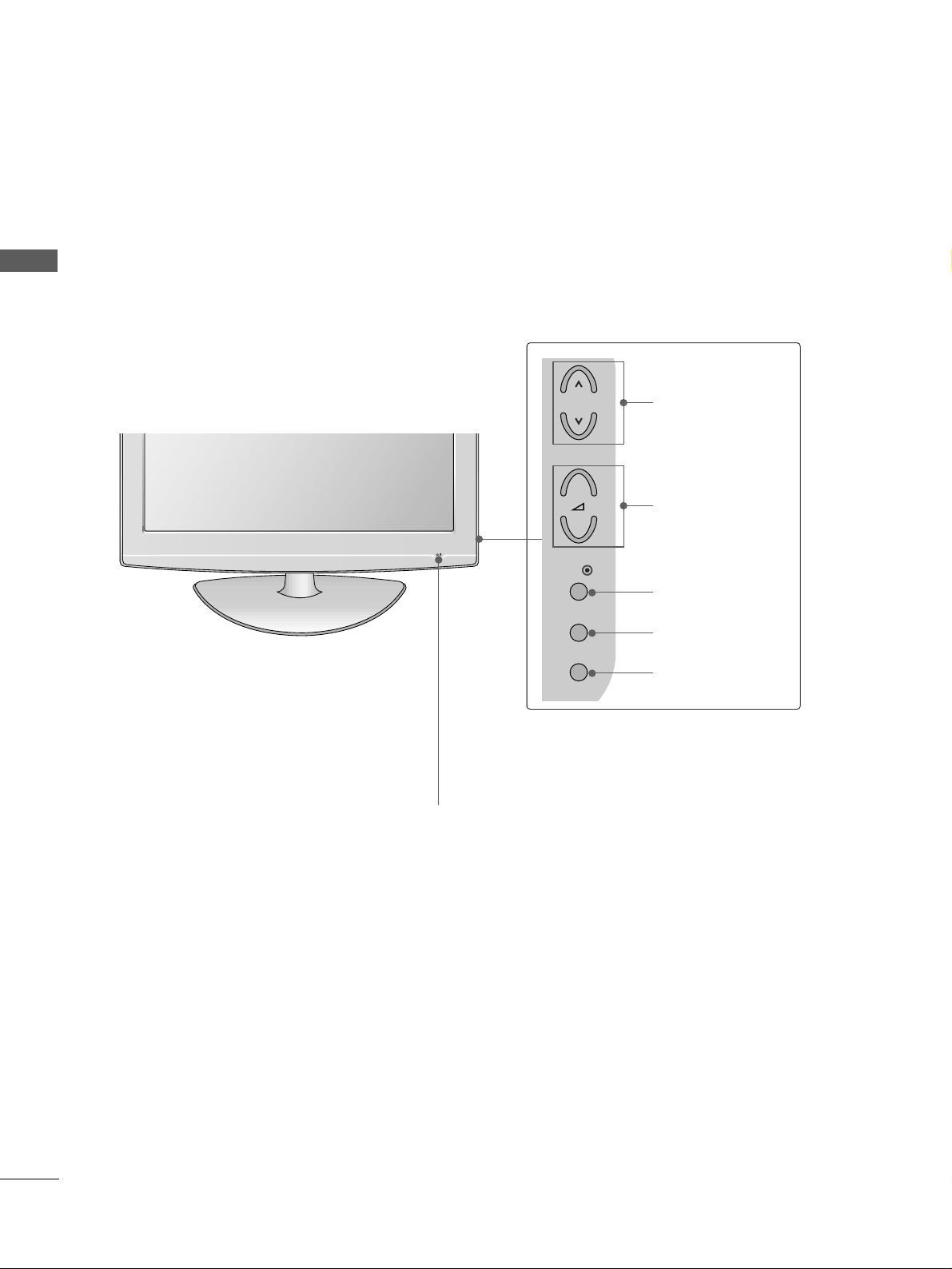
FRONT PANEL CONTROLS
PREPARATION
PREPARATION
■
This is a simplified representation of the front panel. Image shown may differ from your TV.
■
If your product has a protection film attached, remove the film and then wipe the product with a polishing
cloth.
POWER
Remote Control Sensor
Power/Standby Indicator
• illuminates red in standby mode.
• illuminates blue when the TV is switched on.
Note:
You can adjust
PPoowweerr IInnddiiccaattoorr
in
the Option menu.
P
MENU
INPUT
OK
+
-
PROGRAMME
VOLUME
OK
MENU
INPUT
5
PREPARATION
1
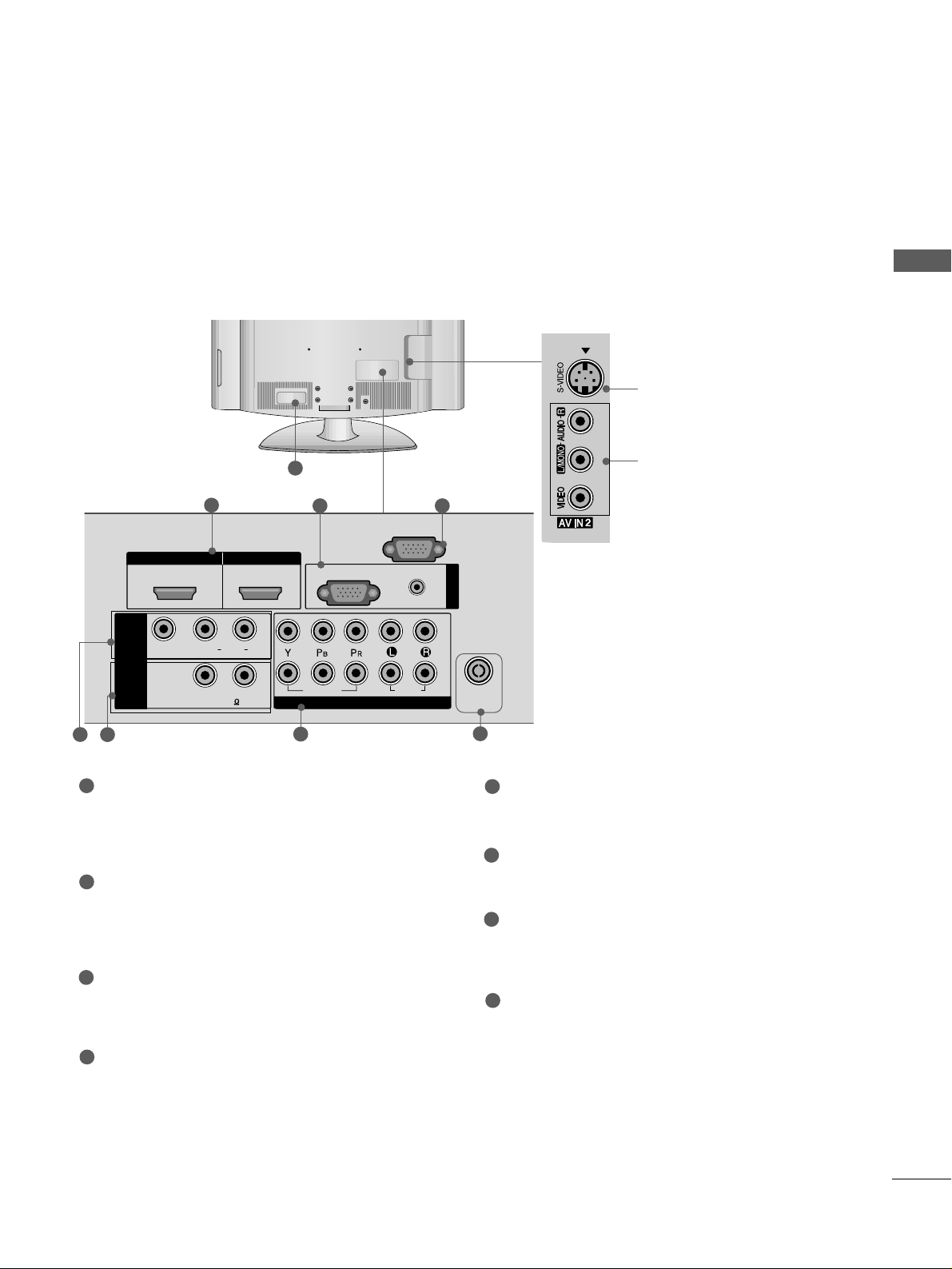
S-Video Input
Connect S-Video out from
an S-VIDEO device.
Audio/Video Input
Connect audio/video output from an external
device to these jacks.
HDMI IN HDMI IN HDMI/DVI IN HDMI/DVI IN
1
1
2
2
AUDIO
RGB
(PC)
RGB INRGB IN
COMPONENT INCOMPONENT IN
AUDIO
VIDEO
L( MONO)
R
AUDIOAUDIO
ANTENNA
IN
(RGB/DVI)
VIDEOVIDEO
RS-232C IN
(CONTROL)
-
+
MONO(8 )MONO(8 )
AV IN 1
SPEAKER
OUT
3 4
2
7
5
Power Cord Socket
This TV operates on an AC power. The voltage is
indicated on the Specifications page. Never
attempt to operate the TV on DC power.
HDMI Input
Connect a HDMI signal to HDMI IN.
Or DVI(VIDEO)signal to HDMI/DVI port with DVI
to HDMI cable.
RGB/Audio Input
Connect the monitor output from a PC to the
appropriate input port.
RS-232C Input
(CONTROL) Port
Connect the serial port of the control devices to
the RS-232C jack.
(This feature is not available for all models.)
Audio/Video Input (AV IN 1)
Connect audio/video output from an external
device to these jacks.
SPEAKER OUTPUT
Audio out for a external speaker system.
Component Input
Connect a component video/audio device to
these jacks.
Antenna Input
Connect RF antenna to this jack.
1
2
3
4
5
6
7
8
6
8
BACK PANEL INFORMATION
A
Image shown may differ from your TV.
6
PREPARATION
PREPARATION
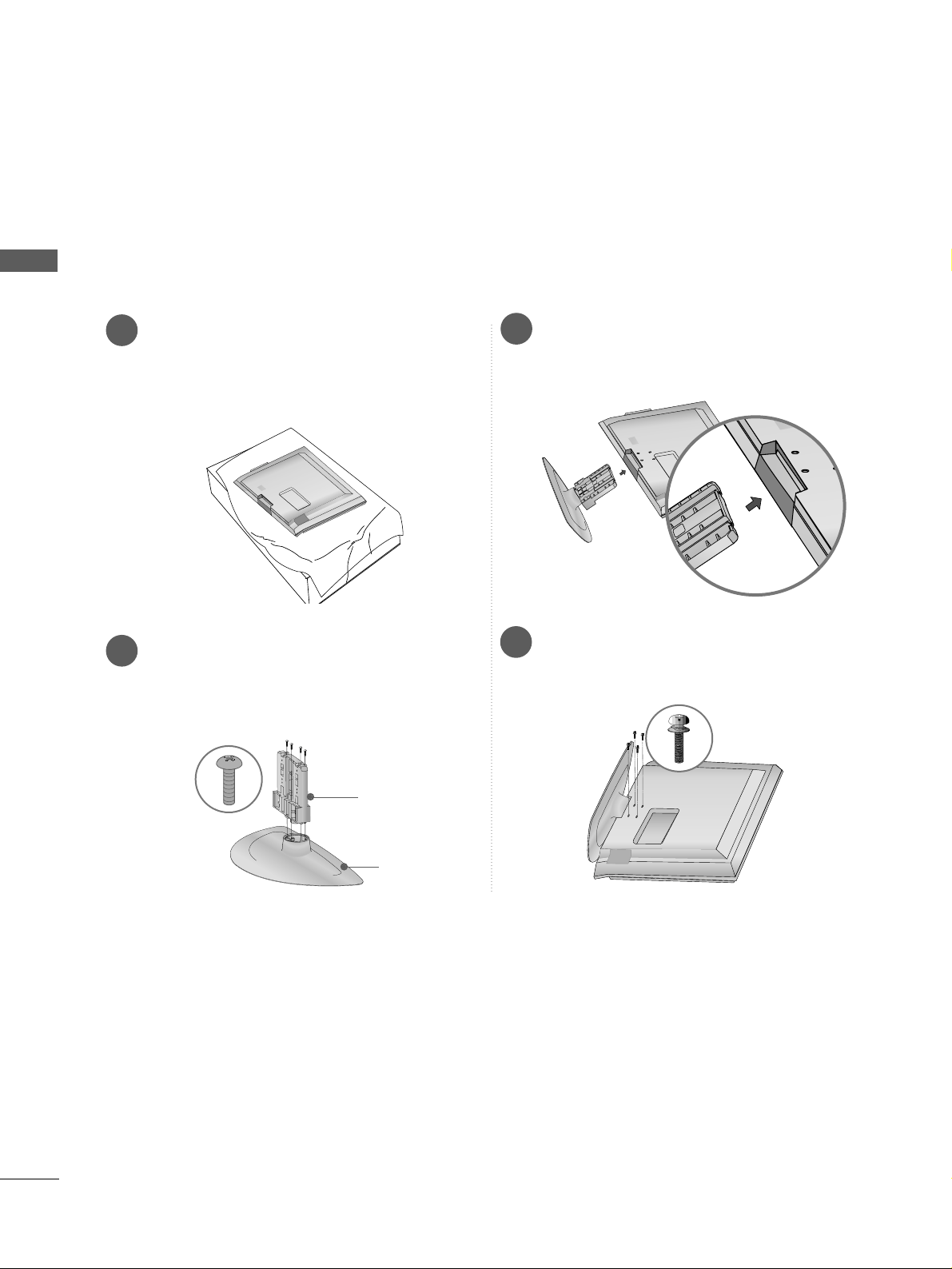
1
3
4
Carefully place the TV screen side down on a
cushioned surface to protect the screen from
damage.
2
Assemble the parts of the
SS ttaann dd BBooddyy
with
the
CCoovv eerr BBaassee
of the TV.
Assemble the TV as shown.
Fix the 4 bolts securely using the holes in the
back of the TV.
Stand Body
Cover Base
STAND INSTALLATION
26/32/37/42LG3
***
■
Image shown may differ from your TV
■
When assembling the desk type stand, check whether the bolt is fully tightened. (If not tightened fully, thep
roduct can tilt forward after the product installation.) If you tighten the bolt with excessive force, the boltcan
deviate from abrasion of the tightening part of the bolt.
7
PREPARATION
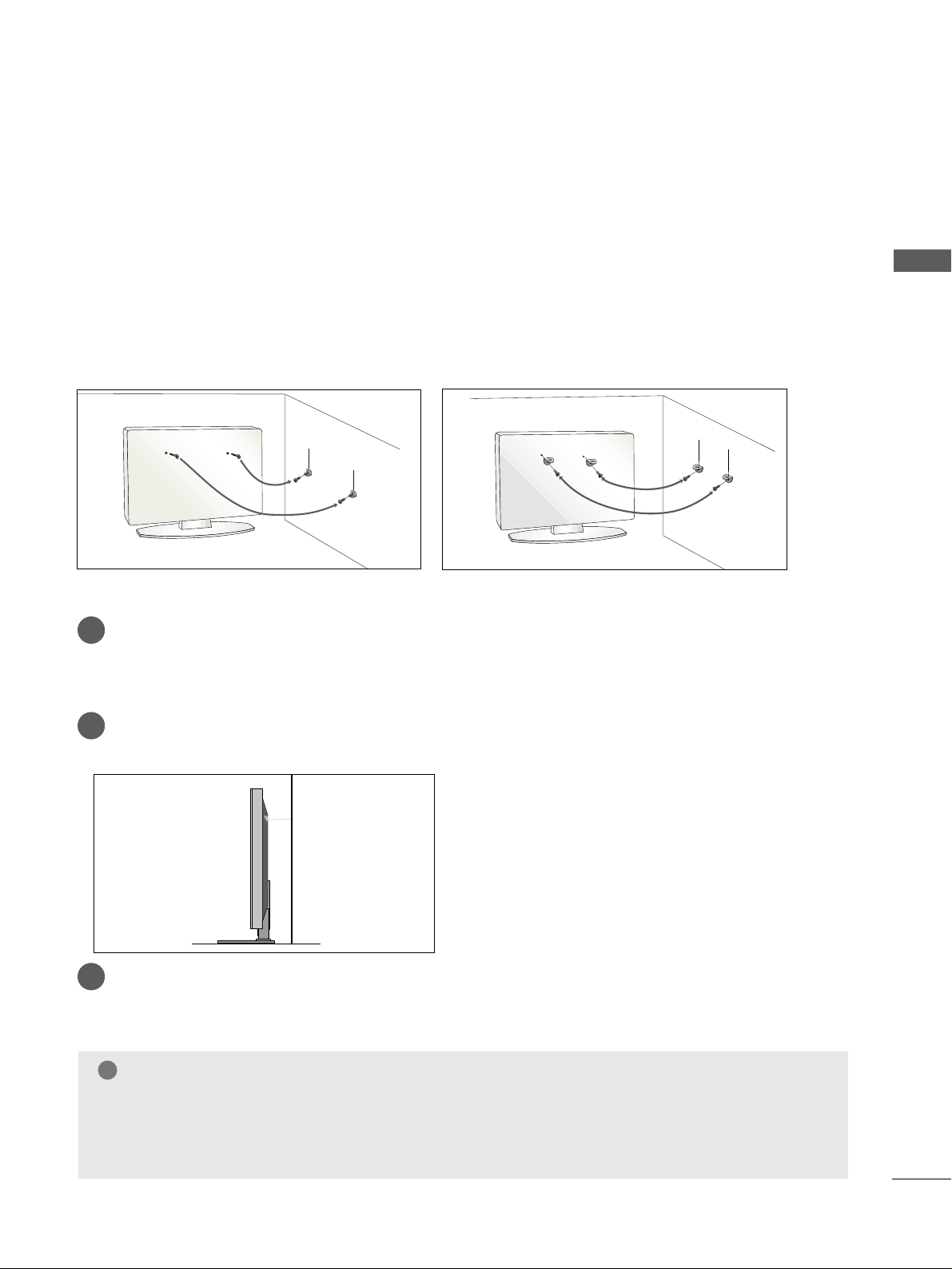
PLEASE SET IT UP CAREFULLY SO THE PRODUCT DOES NOT
FALL OVER.
A
You should purchase necessary components to fix the TV to the wall on the market.
A
Position the TV close to the wall to avoid the possibility of it falling when pushed.
A
The instructions shown below are a safer way to
set up the TV, which is to fix it to the wall, avoiding the
possibility of it falling forwards if pulled. This will prevent the TV from falling forward and causing injury.
This will also prevent the TV from damage. Ensure that children do not climb or hang from the TV.
NOTE
!
G
When moving the TV undo the cords first.
G
Use a platform or cabinet string and large enough to support the size and weight of the TV.
G
To use the TV safely make sure that the height of the bracket on the wall and on the TV is the same.
3
1
2
Use the eye-bolts or TV brackets/bolts to fix the product to the wall as shown in the picture.
(If your TV has bolts in the eyebolts, loosen then bolts.)
* Insert the eye-bolts or TV brackets/bolts and tighten them securely in the upper holes.
Secure the wall brackets with bolts to the wall.
Ensure that both brackets are even.
3
Use a strong cord to secure the TV.
Secure the cord in such a way that it becomes taught when the TV is in position.
2
1
2
1

8
PREPARATION
PREPARATION
BACK COVER FOR WIRE ARRANGEMENT
Connect the cables as necessary.
To connect additional equipment, see the
External Equipment Setup section of the
manual.
Secure the power cable with the PROTECTIVE
BRACKET and the screw as shown. It will help
prevent the power cable from being removed
by accident.
1
Open the
CCAABBLLEE MMAANNAAGGEEMMEENNTT CCLLIIPP
as
shown and manage the cables.
2
CABLE MANAGEMENT CLIP
Fit the
CCAABBLLEE MMAANNAAGGEEMMEENNTT CCLLIIPP
as
shown.
3
NOTE
!
GG
Do not use the CABLE MANAGEMENT CLIP to lift the TV.
- If the TV is dropped, you may be injured or the TV may be damaged.
PROTECTIVE BRACKET
9
PREPARATION
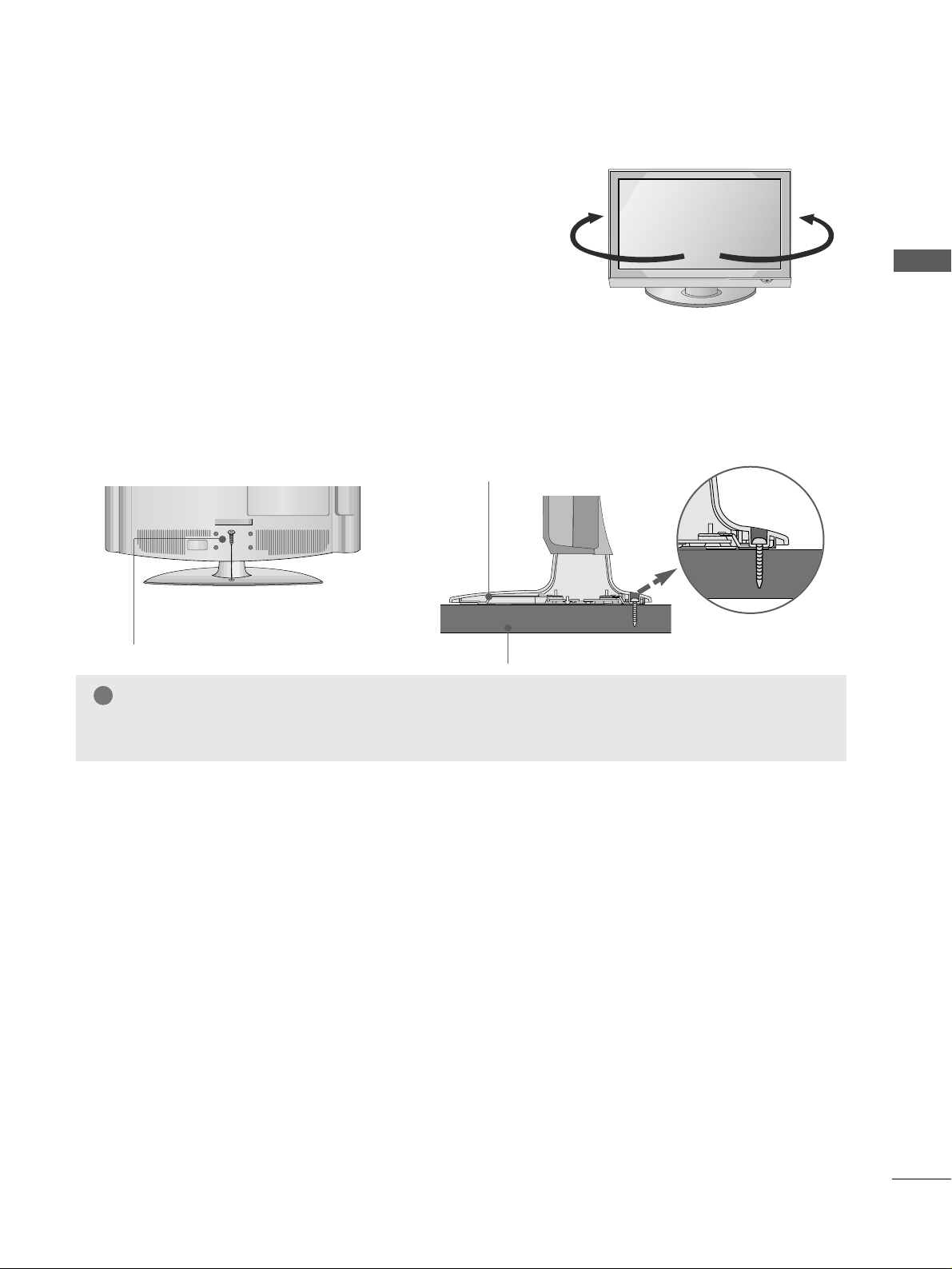
SWIVEL STAND
This feature is not available for all models.
After installing the TV, you can adjust the TV manually
to the left or right direction by 20 degrees to suit your
viewing position.
Attaching the TV to a desk
(Only 26/32/37/42LG3***)
The TV must be attached to desk so it cannot be pulled in a forward/backward direction, potentially causing
injury or damaging the product. Use only an attached screw.
1-Screw
(provided as parts of the product)
Desk
Stand
WARNING
!
GG
To prevent TV from falling over, the TV should be securely attached to the floor/wall per installation
instructions. Tipping, shaking, or rocking the machine may cause injury.
10
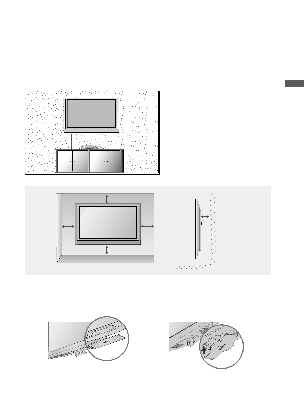
■
The TV can be installed in various ways such as on a wall, or on a desktop etc.
■
The TV is designed to be mounted horizontally.
PREPARATION
PREPARATION
PREPARATION
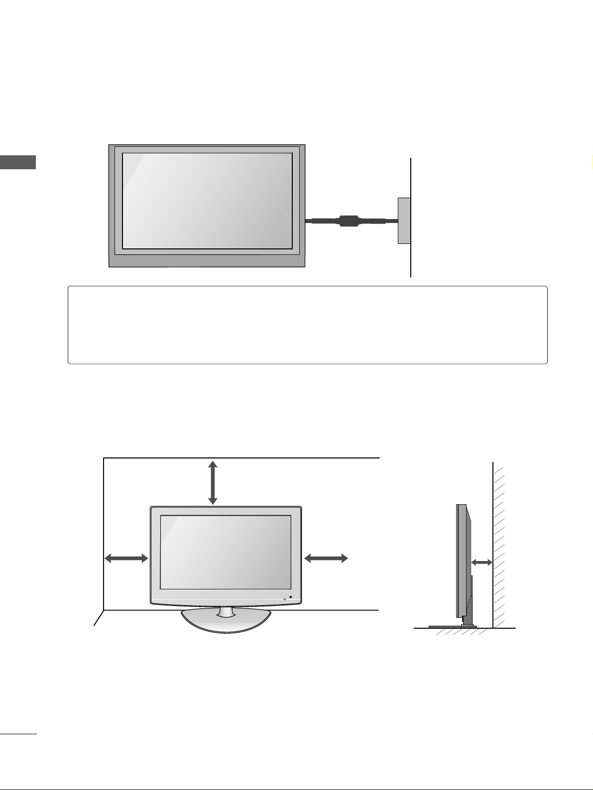
DESKTOP PEDESTAL INSTALLATION
For adequate ventilation allow a clearance of 4” (10cm) all around the TV .
4 inches
4 inches
4 inches
4 inches
Power Supply
Circuit breaker
EARTHING
Ensure that you connect the earth wire to prevent possible electric shock. If grounding methods are not
possible, have a qualified electrician install a separate circuit breaker.
Do not try to earth the TV by connecting it to telephone wires, lightening rods or gas pipes.
11
PREPARATION
WALL MOUNT: HORIZONTAL INSTALLATION
For adequate ventilation allow a clearance of 4” (10cm) all around the TV. We recommend that you use a wall
mounting bracket of LG brand when mounting the TV to a wall.
4 inches
4 inches
4 inches
4 inches
4 inches
When installing the wall-mounted unit, use the protection cover for desk-type stand installation.
NOT USING THE DESK-TYPE STAND
or
RGB IN
ANTENNA
IN
12
PREPARATION
PREPARATION
PREPARATION
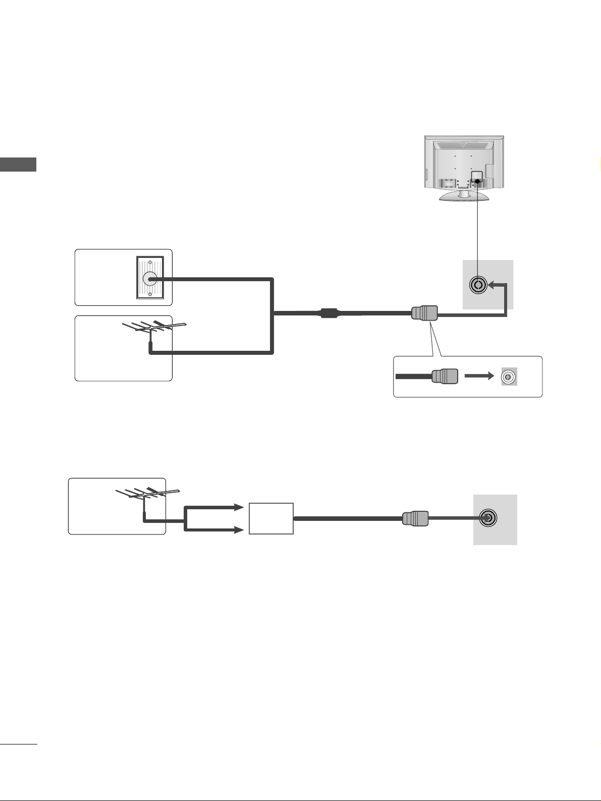
ANTENNA CONNECTION
■
For optimum picture quality, adjust antenna direction.
■
An antenna cable and converter are not supplied.
■
To prevent damage do not connect to the mains outlet until all connections are made between the devices.
RGB IN
ANTENNA
IN
Multi-family Dwellings/Apartments
(Connect to wall antenna socket)
Single-family Dwellings /Houses
(Connect to wall jack for outdoor antenna)
Outdoor
Antenna
Wall
Antenna
Socket
RF Coaxial Wire (75 ohm)
Antenna
UHF
Signal
Amplifier
VHF
■
In poor signal areas, to achieve better picture quality it may be necessary to install a signal amplifier to the
antenna as shown above.
■
If signal needs to be split for two TVs,use an antenna signal splitter for connection.
13
EXTERNAL EQUIPMENT SETUP
EXTERNAL EQUIPMENT SETUP
■
To avoid damaging any equipment, never plug in any power cords until you have finished connecting all equipment.
■
Image shown may differ from your TV.
VIDEO
MONO(8 )
1
2
COMPONENT IN
AUDIO
VIDEO
HDMI/DVI IN
HDMI IN HDMI/DVI IN
1
1
2
2
RGB IN
COMPONENT IN
AUDIO
VIDEO
MONO(8 )
HDMI IN HDMI/DVI IN
1
1
2
2
RGB IN
COMPONENT IN
AUDIO
VIDEO
MONO(8 )
1 2
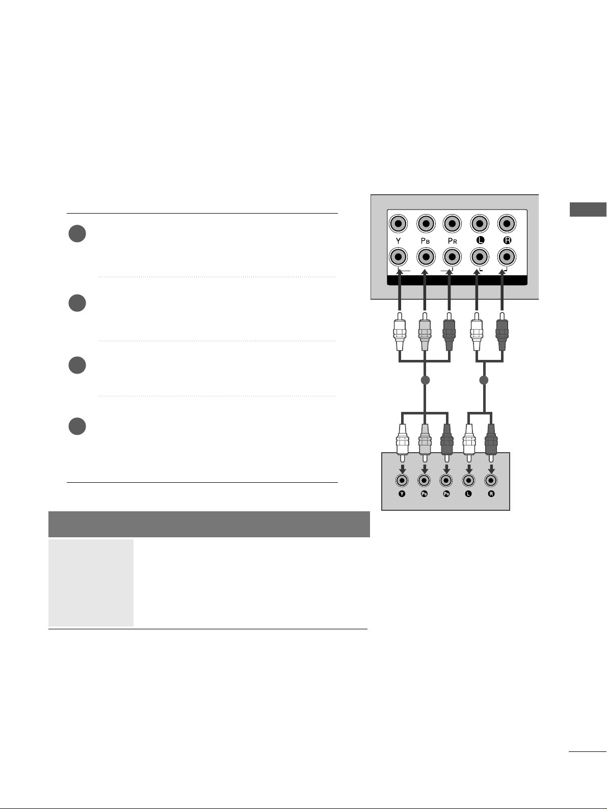
HD RECEIVER SETUP
Connecting with a component cable
Connect the video outputs (Y, P
B, PR
)
of the digital TV
top box to the
CCOOMMPP OONNEE NNTT IINN VVII DDEEOO
jacks on the
TV.
Connect the audio output of the digital set-top box to
the
CCOOMMPP OONNEE NNTT IINN AAUU DDIIOO
jacks on the TV.
Turn on the digital set-top box.
(
Refer to the owner’s manual for the digital set-top box.
)
Select
CCoommppoo nneenntt11
input source using the
IINNPP UUTT
button on the remote control.
If connected to
CCOOMMPP OONNEE NNTT IINN22
, select
CCoommppoo nneenntt22
input source.
2
3
4
1
Signal
480i/576i
480p/576p
720p/1080i
1080p
Component
Yes
Yes
Yes
Yes
(Only 50Hz, 60Hz)
HDMI1/DVI, HDMI2
No
Yes
Yes
Yes
(24Hz, 30Hz, 50Hz, 60Hz)
14
EXTERNAL EQUIPMENT SETUP
EXTERNAL EQUIPMENT SETUP
COMCOMPONENT IN
VIDEO
L( MONO)
R
AUDIOAUDIO
VIDEOVIDEO
-
+
MONO(8 )MONO(8 )
IN 1
UT
HDMI IN HDMI DVI IN
HDMI/DVI IN HDMI/DVI IN
1
COMPONENT IN
AUDIO
VIDEO
MONO(8 )
1
2
HDMI IN HDMI DVI IN
HDMI/DVI IN
1
HDMI IN HDMI/DVI IN
1
1
2
2
RGB IN
COMPONENT IN
AUDIO
VIDEO
MONO(8 )
COMPONENT IN
1
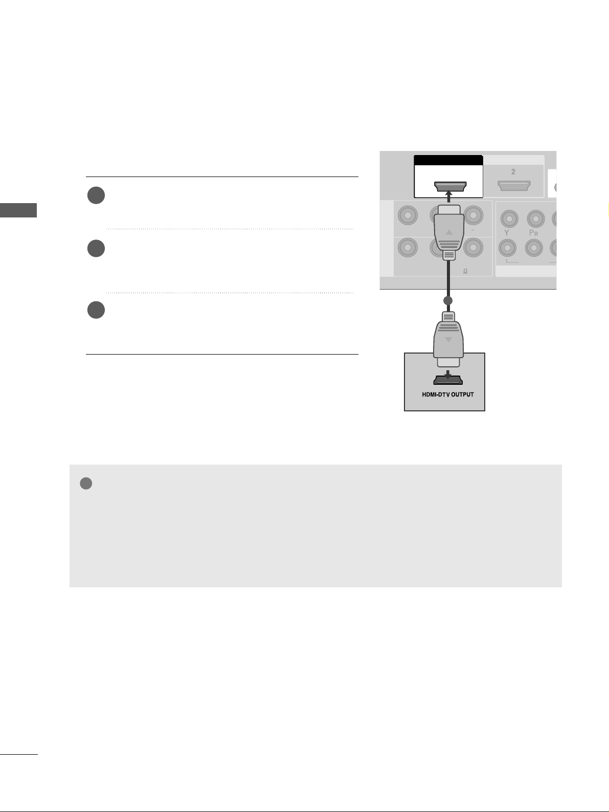
Connecting a set-top box with a HDMI cable
Connect the HDMI output of the digital set-top box to
the
HHDDMMII//DD VVII IINN 11
or
HHDDMMII IINN 22
jack on the TV.
Select
HHDDMMII11// DDVV II
or
HHDDMM II22
input source using the
IINNPP UUTT
button on the remote control.
Turn on the digital set-top box.
(
Refer to the owner’s manual for the digital set-top box.
)
2
3
1
GG
TV can receive the video and audio signal simultaneously with using a HDMI cable.
GG
If the digital set-top box supports Auto HDMI function, the output resolution of the source device will
be automatically TV to 1280x720p.
GG
If the digital set-top box player does not support Auto HDMI, you need to TV the output resolution
appropriately.
To get the best picture quality, adjust the output resolution of the source device to 1280x720p.
NOTE
!
15
EXTERNAL EQUIPMENT SETUP
1
2
COMPONENT INCOMPONENT IN
AUDIO
VIDEO
L( MONO)
R
AUDIOAUDIO
VIDEOVIDEO
-
+
MONO(8 )MONO(8 )
AV IN 1
SPEAKER
OUT
HDMI IN HDMI DVI IN
HDMI/DVI IN HDMI/DVI IN
1
RGB
(PC)
RGB IN
RS-232C IN
(CONTROL)
AUDIO
(RGB/DVI)
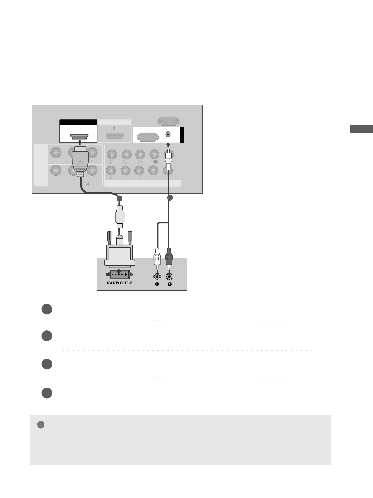
1
2
Connect the DVI output of the digital set-top box to the
HHDDMMII//DD VVII IINN 11
jack on the TV.
Connect the audio output of the digital set-top box to the
AAUUDDIIOO((RRGGBB // DDVVII))
jack on the TV.
Turn on the digital set-top box. (Refer to the owner’s manual for the digital set-top box.
)
Select
HHDDMMII11//DD VVII
input source using the
IINNPP UUTT
button on the remote control.
2
3
4
1
Connecting with a HDMI to DVI cable
GG
HDMI2 source does not support DVI source.
GG
If the Set-Top Box has a DVI output and no HDMI output, a separated audio connection is necessary.
GG
If the Set-Top Box does not support Auto DVI, you need to set the output resolution appropriately.
NOTE
!
16
EXTERNAL EQUIPMENT SETUP
EXTERNAL EQUIPMENT SETUP
1
2
COMPONENT IN
AUDIO
VIDEO
1 2
DVD SETUP
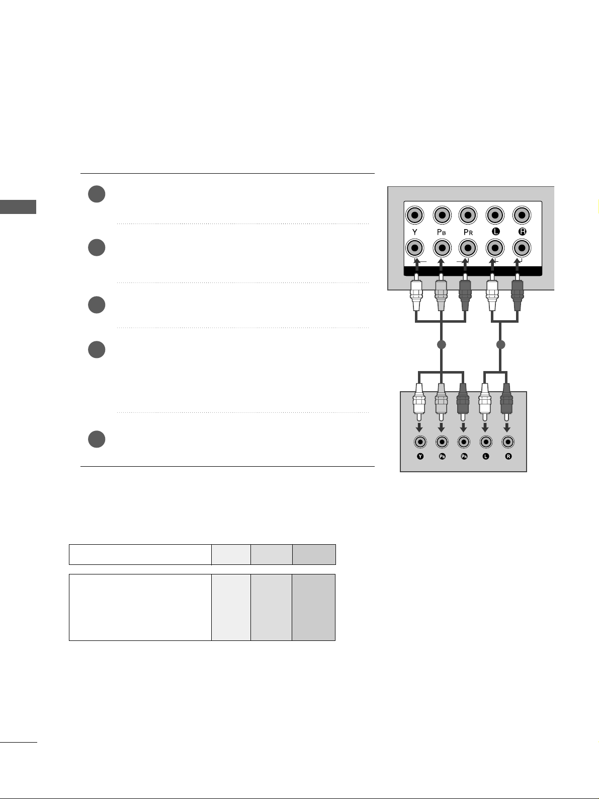
Connecting with a component cable
Component Input ports
To achieve better picture quality, connect a DVD player to the component input ports as shown below.
Component ports on the TV
YPB PR
Video output ports
on DVD player
Y
Y
Y
Y
PB
B-Y
Cb
Pb
P
R
R-Y
Cr
Pr
Connect the video outputs (Y, P
B, PR
)
of the DVD to the
CCOOMMPP OONNEE NNTT IINN VVII DDEEOO
jacks on the TV.
Connect the audio outputs of the DVD to the
CCOOMMPP OONNEE NNTT IINN AAUU DDIIOO
jacks on the TV.
Turn on the DVD player, insert a DVD.
Select
CCoommppoonneenntt11
input source using the
IINNPP UUTT
button
on the remote control.
If connected to
CCOOMMPP OONNEE NNTT IINN22
, select
CCoommppoo nneenntt 22
input source.
Refer to the DVD player's manual for operating instructions.
2
3
4
5
1
17
EXTERNAL EQUIPMENT SETUP
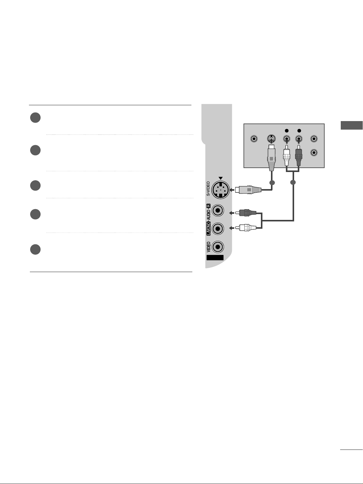
Connecting with a S-Video cable
Connect the S-VIDEO output of the DVD to the
SS --VVIIDDEE OO
input on the TV.
Connect the audio outputs of the DVD to the
AAUUDDIIOO
input jacks on the TV.
Turn on the DVD player, insert a DVD.
Select
AAVV 22
input source using the
IINNPP UUTT
button on
the remote control.
Refer to the DVD player's manual for operating
instructions.
2
3
4
5
1
AV IN 2
L R
S-VIDEOVIDEO
OUTPUT
SWITCH
ANT IN
ANT OUT
1
2
18
EXTERNAL EQUIPMENT SETUP
EXTERNAL EQUIPMENT SETUP
COMPCOMPONENT IN
VIDEO
L( MONO)
R
AUDIOAUDIO
VIDEOVIDEO
-
+
MONO(8 )MONO(8 )
1
HDMI IN HDMI DVI IN
HDMI/DVI IN HDMI/DVI IN
1
1
2
COMPONENT IN
HDMI IN HDMI DVI IN
AV IN 2
L/ MONO
R
AUDIO
VIDEO
1
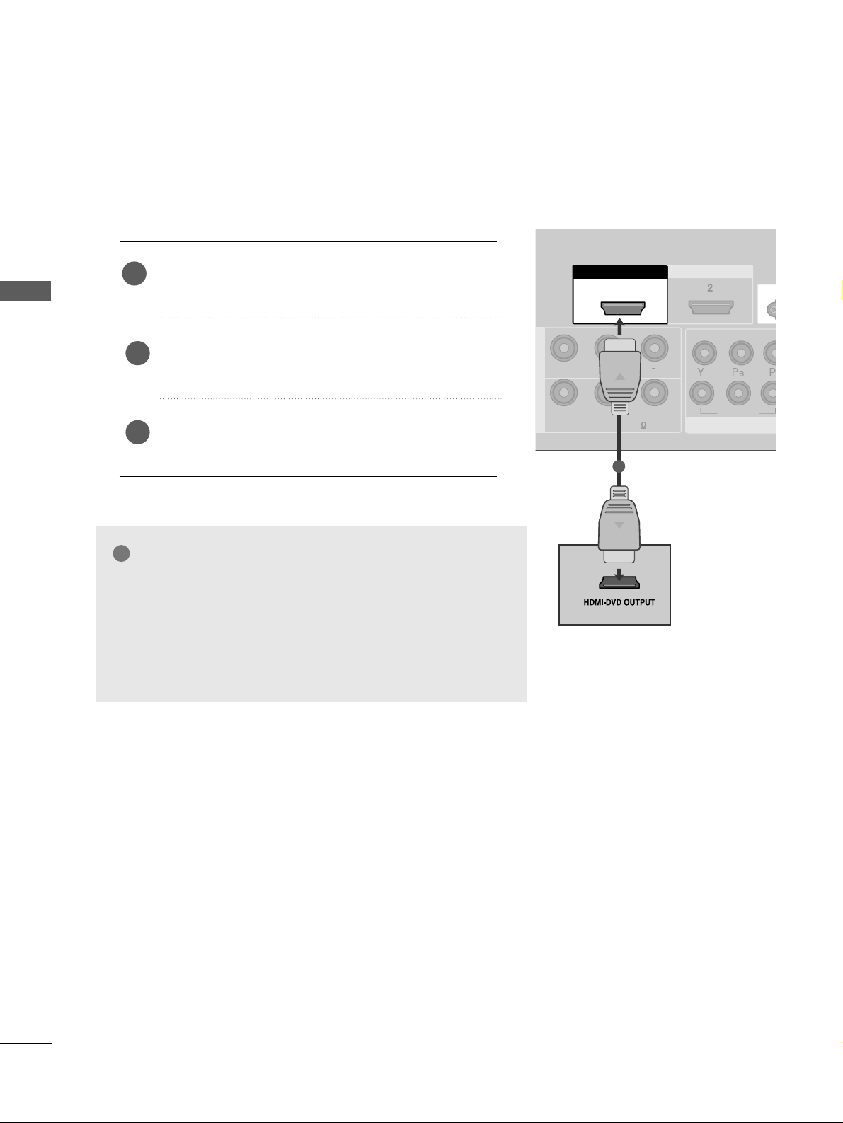
Connecting with a HDMI cable
Connect the HDMI output of the DVD to the
HHDDMMII//DD VVII IINN 11
or
HHDDMMII IINN 22
jack on the TV.
Select
HHDDMMII11// DDVV II
or
HHDDMM II22
input source using the
IINNPP UUTT
button on the remote control.
Refer to the DVD player's manual for operating instructions.
1
GG
The TV can receive video and audio signals simultaneously
when using a HDMI cable.
GG
If the DVD player supports Auto HDMI function, the output resolution of the source device will be automatically TV to 1280x720p.
GG
If the DVD player does not support Auto HDMI, you must TV
the output resolution appropriately.
To get the best picture quality, adjust the output resolution of
the source device to 1280x720p.
NOTE
!
2
3
19
EXTERNAL EQUIPMENT SETUP
ANTENNA
IN
OUTPUT
SWITCH
ANT IN
R
S-VIDEO VIDEO
ANT OUT
L
1
2
COMPONENT INCOMPONENT IN
AUDIO
VIDEO
HDMI IN HDMI DVI IN
Wall Jack
Antenna
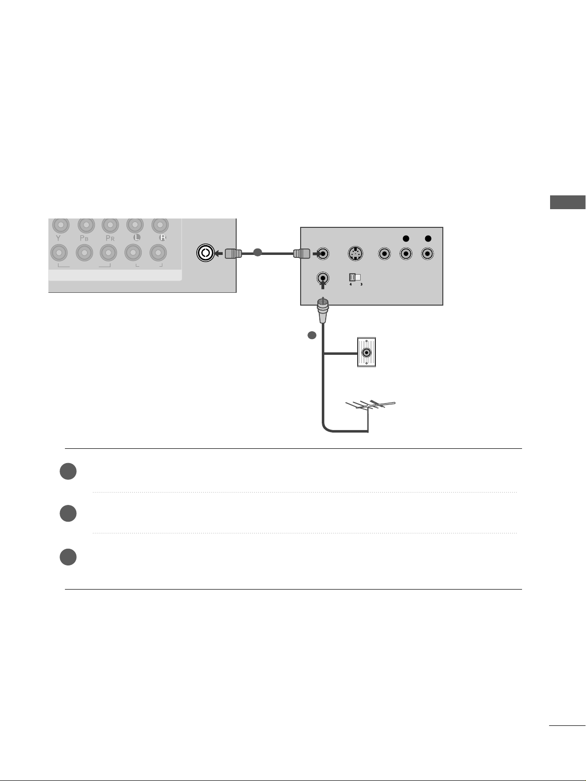
VCR SETUP
Connecting with a RF cable
■
To avoid picture noise (interference), allow adequate distance between the VCR and TV.
■
Typically a frozen still picture from a VCR. If 4:3 picture format is used for an extended period the fixed
images on the sides of the screen may remain visible.
Connect the
AANNTT OOUU TT
socket of the VCR to the
AANNTTEE NNNNAA IINN
socket on the TV.
Connect the antenna cable to the
AANNTT IINN
socket of the VCR.
Press the
PPLLAA YY
button on the VCR and match the appropriate programme between the TV and VCR for
viewing.
1
2
2
3
1
20
EXTERNAL EQUIPMENT SETUP
EXTERNAL EQUIPMENT SETUP
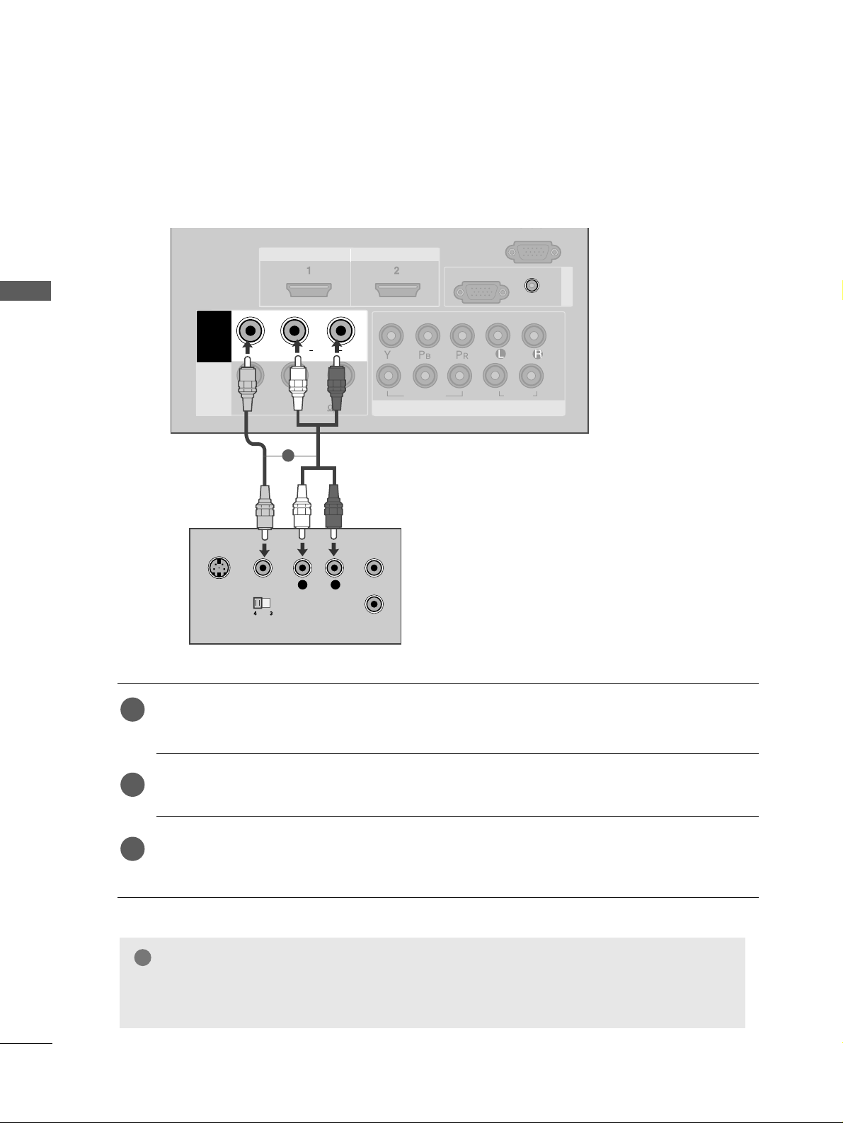
Connecting with a RCA cable
1
2
COMPONENT INCOMPONENT IN
AUDIO
VIDEO
L( MONO)
R
AUDIOAUDIO
VIDEOVIDEO
-
+
MONO(8 )MONO(8 )
AV IN 1
SPEAKER
OUT
HDMI IN
HDMI/DVI IN HDMI/DVI IN
RGB
(PC)
RGB IN
RS 232C IN
(CONTROL)
AUDIO
(RGB/DVI)
L
R
S-VIDEO
VIDEO
OUTPUT
SWITCH
ANT IN
ANT OUT
COMPONENT IN
AUDIO
VIDEO
MONO(8 )
HDMI IN HDMI DVI IN
HDMI/DVI IN
1
Connect the
AAUUDD IIOO/VVIIDDEE OO
jacks between TV and VCR. Match the jack colours (Video = yellow,
Audio Left = white, and Audio Right = red)
Insert a video tape into the VCR and press PLAY on the VCR. (Refer to the VCR owner’s manual.
)
Select
AAVV 11
input source using the
IINNPP UUTT
button on the remote control.
If connected to
AAVV IINN22
, select
AAVV 22
input source.
1
2
3
GG
If you have a mono VCR, connect the audio cable from the VCR to the
AAUUDD II OO LL// MMOONNOO
jack
of the TV.
NOTE
!
1
21
EXTERNAL EQUIPMENT SETUP
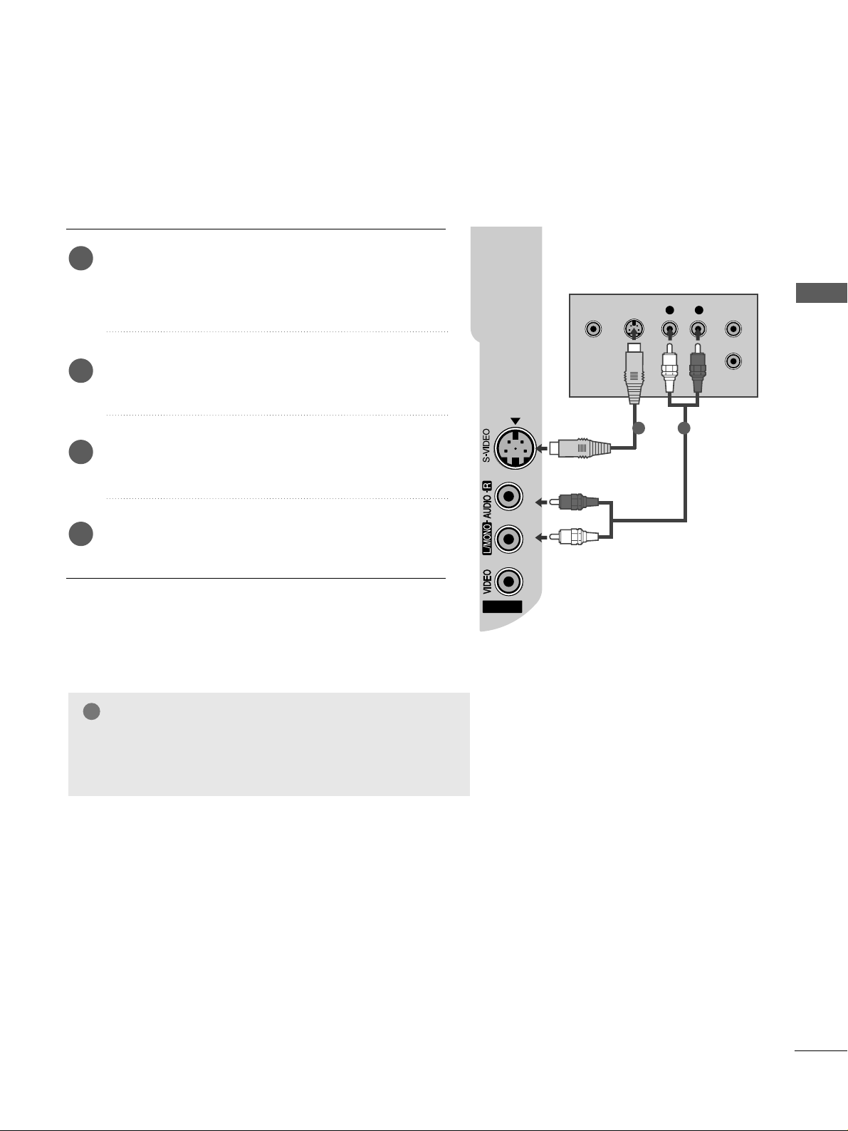
GG
If both S-VIDEO and VIDEO sockets have been conneced to
the S-VHS VCR simultaneously, only the S-VIDEO can be
received.
NOTE
!
AV IN 2
L R
S-VIDEOVIDEO
OUTPUT
SWITCH
ANT IN
ANT OUT
Connecting with a S-Video cable
Connect the S-VIDEO output of the VCR to the
SS --VV IIDDEEOO
input on the TV. The picture quality is
improved; compared to normal composite (RCA cable)
input.
Connect the audio outputs of the VCR to the
AAUUDD IIOO
input jacks on the TV.
Insert a video tape into the VCR and press PLAY on
the VCR. (Refer to the VCR owner’s manual.)
Select
AA VV 22
input source using the
IINNPP UUTT
button on
the remote control.
2
3
4
1
1 2
22
EXTERNAL EQUIPMENT SETUP
EXTERNAL EQUIPMENT SETUP
AV IN 2
L R
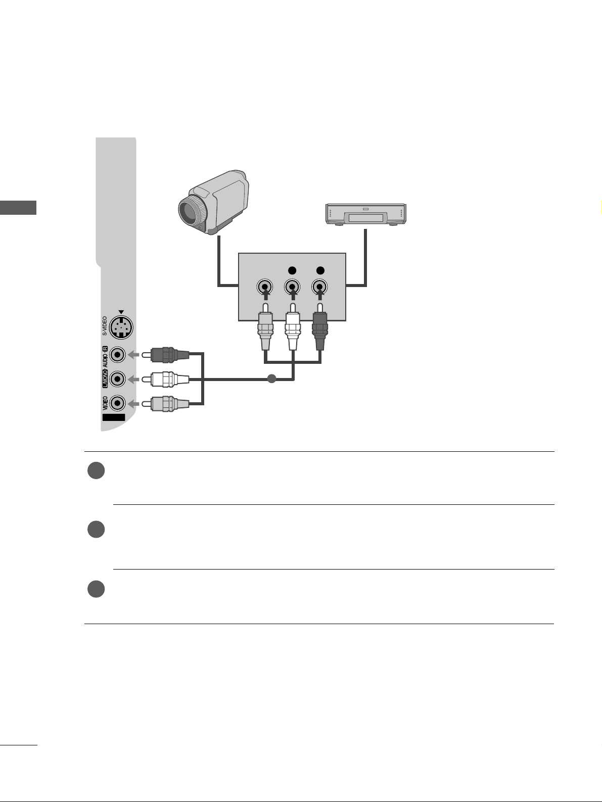
VIDEO
Camcorder
Video Game Set
1
OTHER A/V SOURCE SETUP
Connect the
AAUUDD IIOO/VVIIDDEE OO
jacks between TV and external equipment. Match the jack colours
.
(
Video = yellow, Audio Left = white, and Audio Right = red
)
Select
AAVV 22
input source using the
IINNPP UUTT
button on the remote control.
If connected to
AAVV IINN11
, select
AAVV 11
input source.
Operate the corresponding external equipment.
Refer to external equipment operating guide.
1
2
3
23
EXTERNAL EQUIPMENT SETUP
COMPONENT IN
AUDIO
VIDEO
MONO(8 )
HDMI IN HDMI DVI IN
HDMI/DVI IN
1
1
2
COMPONENT INCOMPONENT IN
AUDIO
VIDEO
L( MONO)
R
AUDIOAUDIO
VIDEOVIDEO
-
+
MONO(8 )MONO(8 )
IN 1
HDMI IN HDMI DVI IN
RGB
(PC)
RGB IN
AUDIO
(RGB/DVI)
RGB OUTPUT
AUDIO
1
2
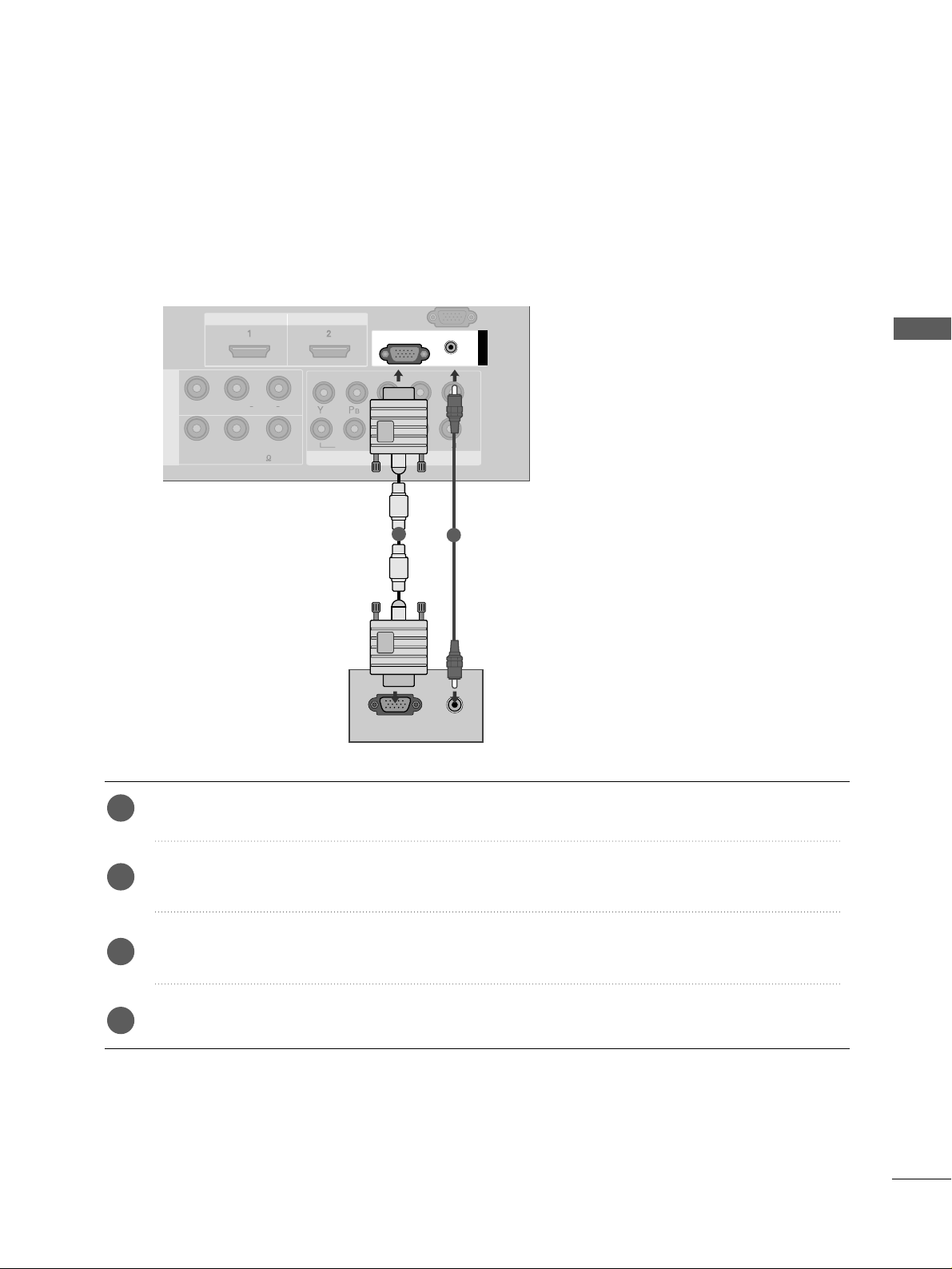
PC SETUP
This TV provides Plug and Play capability, meaning that the PC adjusts automatically to the TV's settings.
Connecting with a D-sub 15 pin cable
Connect the RGB output of the PC to the
RRGG BB((PP CC
))
jack on the TV.
Connect the PC audio output to the
AAUUDDIIOO((RRGGBB // DDVVII))
jack on the TV.
Turn on the PC and the TV.
Select
RRGGBB PPCC
input source using the
IINNPPUUTT
button on the remote control.
2
3
4
1

24
EXTERNAL EQUIPMENT SETUP
EXTERNAL EQUIPMENT SETUP
NOTE
!
GG
To enjoy vivid picture and sound, connect the PC
to the TV.
GG
Avoid keeping a fixed image on the TV ’s screen
for prolonged periods of time.The fixed image
may become permanently imprinted on the
screen;use a screen saver when possible.
GG
Connect the PC to the RGB (PC) port of the TV;
change the resolution output of PC accordingly.
GG
There may be interference relating to resolution,
vertical pattern, contrast or brightness in PC
mode. Change the PC mode to another resolution or change the refresh rate to another rate
or adjust the brightness and contrast on the
menu until the picture is clear. If the refresh rate
of the PC graphic card can not be changed,
change the PC graphic card or consult the manufacturer of the PC graphic card.
GG
The synchronization input waveform for
Horizontal and Vertical frequencies are separate.
GG
If the resolution of PC is over SXGA, there will
be no picture on the TV.(Only HD Models)
GG
Connect the audio cable from the PC to the
Audio input on the TV.(Audio cables are not
included with the TV).
GG
If you use too long an RGB-PC cable, there may
be interference on the screen. We recommend
using under 5m of the cable. This provides the
best picture quality.
25
EXTERNAL EQUIPMENT SETUP
Supported Display Resolution
31.47 59.94
31.50 60.00
31.25 50.00
44.96 59.94
45.00 60.00
37.50 50.00
33.72 59.94
33.75 60.00
28.125 50.00
67.432 59. 94
67.5 60
56.25 50
27 24
33.75 30
Resolution
720x480
720x576
1280x720
1920x1080i
1920x1080p
HDMI-DTV mode
Horizontal Vertical
Frequency(kHz) Frequency(Hz)
Resolution
RGB-PC mode
31.468 70.09
31.469 70.09
31.469 59.94
37.879 60.317
48.363 60.004
47.776 59.87
47.720 59. 799
47.70 0 60 .0 0
Horizontal Vertical
Frequency(kHz) Frequency(Hz)
640x350
720x400
640x480
800x600
1024x768
1280x768
1360x768
1366x768
26
EXTERNAL EQUIPMENT SETUP
EXTERNAL EQUIPMENT SETUP
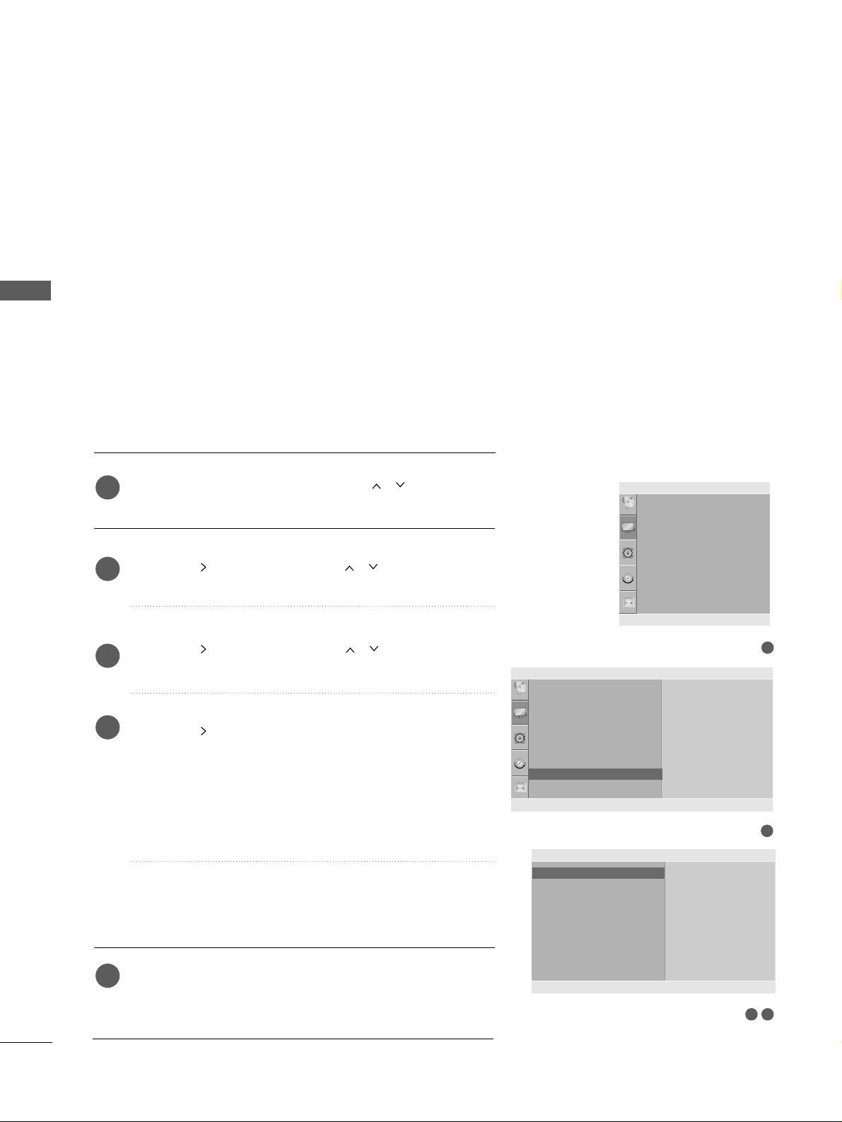
Press the
MMEE NNUU
button and then use
//
button to
select the
PPiiccttuurree
menu.
Press the button and then use
//
button to select
SS ccrreeee nn
.
Press the button and then use
//
button to select
AAuuttoo CC oonn ffiigg ..
.
Press the button to start
AAuuttoo CC oonn ffiigg
..
• When Auto config. has finished, OK will be shown on
screen.
• If the position of the image is still not correct, try Auto
adjustment again.
• If picture needs to be adjusted again after Auto adjustment in RGB (PC), you can adjust the
MMaa nnuuaall CCoonn ffiigg..
.
Press the
MMEENNUU
button to return to normal TV viewing.
Press the
RREETTUURRNN
button to move to the previous menu
screen.
Automatically adjusts picture position and minimizes image
instability. After adjustment, if the image is still not correct,
your TV is functioning properly but needs further adjustment.
AA uuttoo ccoo nn ffiigguu rr ee
This function is for automatic adjustment of the screen position, clock, and phase. The displayed image will be unstable for
a few seconds while the auto configuration is in progress.
1
2
3
4
5
1
3 4
Screen Setup for PC mode
Auto Configure (RGB [PC] mode only)
Picture Mode
Colour Temperature
XD
Advanced
Aspect Ratio
Picture Reset
Screen
Picture
Screen
Auto config.
Manual Config.
XGA Mode
Reset
To Set
Auto Config. G
DE F G
OK RETURN
2
Picture
Picture Mode
Colour Temperature
XD
Advanced
Aspect Ratio
Picture Reset
Screen
To Set
Screen G
DE F G
OK RETURN
DE F G
OK RETURN
27
EXTERNAL EQUIPMENT SETUP
If the picture is not clear after auto adjustment and especially if
characters are still trembling, adjust the picture phase manually.
It’s not available to use Phase, Clock function in COMPONENT
(480i/480p/576i/576p/720p/1080i/1080p), HDMI
(480p/576p/720p/1080i/1080p).
CClloocckk
This function is to minimize any vertical bars or stripes
visible on the screen background the horizontal screen
size will also change.
PP hh aa ssee
This function allows you to remove any horizontal noise
and clear or sharpen the image of characters.
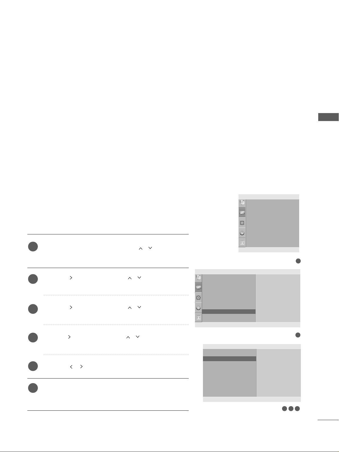
Press the
MMEE NNUU
button and then use
//
button to
select the
PPiiccttuurree
menu.
Press the button and then use
//
button to select
SS ccrreeee nn
.
Press the button and then use
//
button to select
MMaa nnuuaall CCoonn ffiigg..
.
Press the button and then use
//
button to select
PPhh aa ssee, CCll oocc kk, HH--PPoo ssiittiioo nn
or
VV--PPooss iittiioonn
.
Press the
//
button to make appropriate adjustments.
Press the
MMEENNUU
button to return to normal TV viewing.
Press the
RREETTUURRNN
button to move to the previous menu
screen.
1
2
3
4
5
6
Manual Configure (Adjustment for screen Phase, Clock, Position)
(RGB [PC] mode only)
3 4 5
1
Picture Mode
Colour Temperature
XD
Advanced
Aspect Ratio
Picture Reset
Screen
Picture
DE F G
OK RETURN
2
Picture
Picture Mode
Colour Temperature
XD
Advanced
Aspect Ratio
Picture Reset
Screen
To Set
Screen G
DE F G
OK RETURN
Screen
Auto config.
Manual Config.
XGA Mode
Reset
Phase 51
Clock 50
H-Position 50
V-Position 50
Manual Config. G
DE F G
OK RETURN
 Loading...