

LG Electronics 32LG3DDH, 26LG3DCH, 22LG3DCH, 32LG3DCH, 26LG3DDH User Manual
...
22LG3DCH 26LG3DCH 32LG3DCH
22LG3DDH 26LG3DDH 32LG3DDH
Hospital TVs
Commercial Mode Setup Guide
Note: Selected features shown within this guide may not be available on all models.
EXPERIENCED INSTALLER
Commercial Mode Setup
pages 14 – 15
© Copyright 2011, LG Electronics U.S.A., Inc.
Express Script
pages 16 – 17
Cloning Information
pages 30 – 35
P/N: 206-4096 (Rev G)
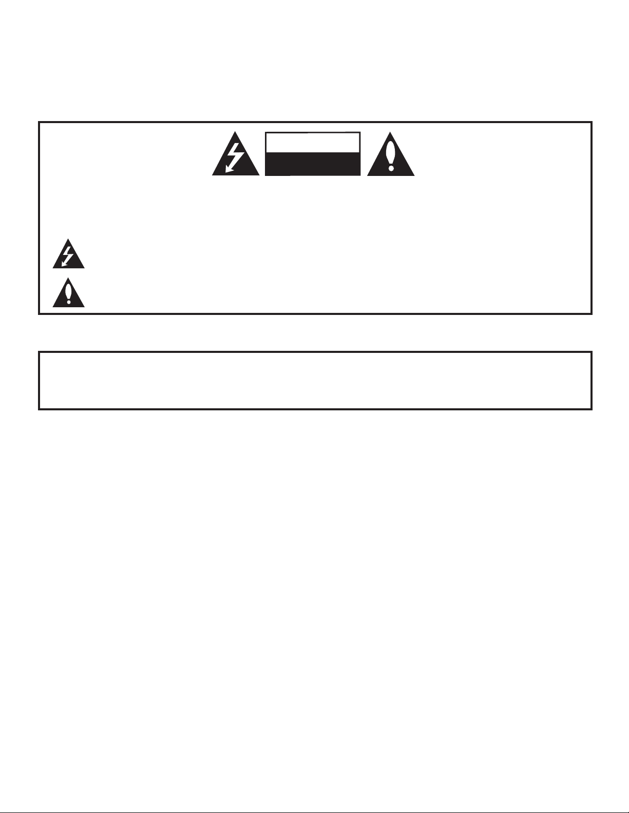
WARNING
RISK OF ELECTRIC SHOCK
DO NOT OPEN
For Customer Support/Service, please call:
1-888-865-3026
The latest product information and documentation is
available online at:
www.LGsolutions.com/products
MODEL and SERIAL NUMBER
The model and serial numbers of this TV are located on the
back of the cabinet. For future reference, LG suggests that
you record those numbers here:
Model No._________________Serial No. _______________
WARNING:
TO REDUCE THE RISK OF ELECTRIC SHOCK DO NOT REMOVE COVER (OR BACK). NO USERSERVICEABLE PARTS INSIDE. REFER TO QUALIFIED SERVICE PERSONNEL.
The lightning flash with arrowhead symbol, within an equilateral triangle, is intended to alert the user to
the presence of uninsulated “dangerous voltage” within the product’s enclosure that may be of sufficient
magnitude to constitute a risk of electric shock to persons.
The exclamation point within an equilateral triangle is intended to alert the user to the presence of important
operating and maintenance (servicing) instructions in the literature accompanying the appliance.
WARNING:
TO PREVENT FIRE OR SHOCK HAZARDS, DO NOT EXPOSE THIS PRODUCT TO RAIN OR MOISTURE.
POWER CORD POLARIZATION:
This product is equipped with a 3-wire grounding-type alternating current power plug. This plug will fit into the power
outlet only one way. This is a safety feature. If you are unable to insert the plug fully into the outlet, contact your electrician to replace your obsolete outlet. Do not defeat the safety purpose of the 3-wire grounding-type plug.
NOTE TO CABLE/TV INSTALLER:
This reminder is provided to call the cable TV system installer’s attention to Article 820-40 of the National Electric
Code (U.S.A.). The code provides guidelines for proper grounding and, in particular, specifies that the cable ground
shall be connected to the grounding system of the building, as close to the point of the cable entry as practical.
REGULATORY INFORMATION:
This equipment has been tested and found to comply with the limits for a Class B digital device, pursuant to Part 15 of
the FCC Rules. These limits are designed to provide reasonable protection against harmful interference when the
equipment is operated in a residential installation. This equipment generates, uses and can radiate radio frequency
energy and, if not installed and used in accordance with the instruction manual, may cause harmful interference to radio
communications. However, there is no guarantee that interference will not occur in a particular installation. If this equipment does cause harmful interference to radio or television reception, which can be determined by turning the equipment off and on, the user is encouraged to try to correct the interference by one or more of the following measures:
• Reorient or relocate the receiving antenna.
• Increase the separation between the equipment and receiver.
• Connect the equipment to an outlet on a circuit different from that to which the receiver is connected.
• Consult the dealer or an experienced radio/TV technician for help.
CAUTION:
Do not attempt to modify this product in any way without written authorization from LG Electronics U.S.A., Inc.
Unauthorized modification could void the user’s authority to operate this product.
COMPLIANCE:
The responsible party for this product’s compliance is: LG Electronics U.S.A., Inc.
1000 Sylvan Avenue, Englewood Cliffs, NJ 07632, USA • Phone: 1-201-816-2000
Marketed and Distributed in the United States by LG Electronics U.S.A., Inc.
1000 Sylvan Avenue, Englewood Cliffs, NJ 07632
2
© Copyright 2011, LG Electronics U.S.A., Inc.
206-4096
IMPORTANT SAFETY INSTRUCTIONS
1. Read these instructions.
2. Keep these instructions.
3. Heed all warnings.
4. Follow all instructions.
5. Do not use this apparatus near water.
6. Clean only with dry cloth.
7. Do not block any ventilation openings. Install in
accordance with the manufacturer’s instructions.
8. Do not install near any heat sources, such as radiators, heat registers, stoves, or other apparatus
(including amplifiers) that produce heat.
9. Do not defeat the safety purpose of the polarized
or grounding-type plug. A polarized plug has two
blades with one wider than the other. A groundingtype plug has two blades and a third grounding
prong. The wide blade or the third prong are provided for your safety. If the provided plug does not
fit into your outlet, consult an electrician for
replacement of the obsolete outlet.
10. Protect the power cord from being walked on or
pinched, particularly at plugs, convenience receptacles, and the point where it exits from the apparatus.
11. Only use attachments/accessories specified by the
manufacturer.
12. Use only with the cart, stand, tripod, bracket, or
table specified by the manufacturer or sold with
the apparatus. When a cart is used, use caution
when moving the cart/apparatus combination in
order to avoid injury from tip-over.
PORTABLE CART WARNING
13.
Refer all servicing to qualifi ed service personnel.
Servicing is required when the apparatus has been
damaged in any way, such as power-supply cord
or plug is damaged, liquid has been spilled or
objects have fallen into the apparatus, the apparatus has been exposed to rain or moisture, does
not operate normally, or has been dropped.
14. Never touch this apparatus or antenna during a thun-
der or lighting storm.
15. When mounting a TV on the wall, make sure not to
install the TV by the hanging power and signal cables
on the back of the TV.
16. Do not allow an impact shock or any objects to fall into
the product, and do not drop objects onto the screen.
17. Power Cord
Caution: It is recommended that appliances be
placed upon a dedicated circuit; that is, a single
outlet circuit which powers only that appliance and
has no additional outlets or branch circuits. Check
the specification page of the Owner’s Manual to be
certain.
Periodically examine the cord of your appliance, and
if its appearance indicates damage or deterioration,
unplug it, discontinue use of the appliance, and have
the cord replaced with an exact replacement part by an
authorized servicer. Protect the power cord from physical or mechanical abuse, such as twisting, kinking, or
pinching or being closed in a door or walked upon. Pay
particular attention to plugs, wall outlets, and the point
where the cord exits the appliance.
Do not use a damaged or loose power cord. Be sure
to grasp the plug when unplugging the power cord. Do
not pull on the power cord to unplug the TV.
18. Overloading
Do not connect too many appliances to the same AC
power outlet as this could result in fire or electric shock.
Do not overload wall outlets. Overloaded wall outlets,
loose or damaged wall outlets, extension cords, frayed
power cords, or damaged or cracked wire insulation
are dangerous. Any of these conditions could result in
fi re or electric shock.
19. Outdoor Use/Wet Location
Warning: To reduce the risk of fi re or elec-
trical shock, do not expose this product to
rain, moisture or other liquids.
Do not touch the TV with wet hands. Do not install this
product near fl ammable objects such as gasoline or
candles or expose the TV to direct air conditioning.
Do not expose to dripping or splashing and do not place
objects fi lled with liquids, such as vases, cups, etc., on
or over the apparatus (e.g., on shelves above the unit).
206-4096
(Continued on next page)
3

IMPORTANT SAFETY INSTRUCTIONS
(Continued from previous page)
20. Grounding
Ensure that you connect the earth ground wire to pre-
vent possible electric shock (i.e., a TV with a threeprong grounded AC plug must be connected to a
three-prong grounded AC outlet). If grounding methods
are not possible, have a qualified electrician install a
separate circuit breaker. Do not try to ground the unit
by connecting it to telephone wires, lightening rods, or
gas pipes.
21. Disconnect Device
The mains plug is the disconnecting device. The plug
must remain readily operable.
As long as this unit is connected to the AC wall outlet,
it is not disconnected from the AC power source even
if you turn off this unit by SWITCH.
22. Outdoor Antenna Grounding
If an outside antenna or cable system is connected to
the product, follow the precautions below.
An outdoor antenna system should not be located in
the vicinity of overhead power lines or other electric
light or power circuits or where it can come into contact with such power lines or circuits as death or serious injury can occur.
Be sure the antenna system is grounded so as to pro-
vide some protection against voltage surges and builtup static charges.
Article 810 of the National Electrical Code (NEC) in the
U.S.A. provides information with respect to proper
grounding of the mast and supporting structure,
grounding of the lead-in wire to an antenna-discharge
unit, size of grounding conductors, location of
antenna-discharge unit, connection to grounding electrodes, and requirements for the grounding electrode.
Antenna Grounding According to NEC, ANSI/NFPA 70
23. Cleaning
When cleaning, unplug the power cord and rub gently
with a soft cloth to prevent scratching. Do not spray
water or other liquids directly on the TV as electric
shock may occur. Do not clean with chemicals such as
alcohol, thinners or benzene.
24. Transporting Product
Make sure the product is turned Off and unplugged
and that all cables have been removed. It may take
two or more people to carry larger TVs. Do not press
against or put stress on the front panel of the TV.
25. Ventilation
Install the TV where there is proper ventilation. Do not
install in a confined space such as a bookcase. Do not
cover the product with cloth or other materials (e.g.,
plastic) while it is plugged in. Do not install in excessively dusty places.
26. Do not touch the ventilation openings, as they may
become hot while the TV is operating.
27. If you smell smoke or other odors coming from the TV
or hear strange sounds, unplug the power cord, and
contact an authorized service center.
28. Do not press strongly on the panel with a hand or
sharp object (e.g., a nail, pencil, or pen) or make a
scratch on it.
29. Keep the product away from direct sunlight.
30. For LCD TV
If the TV feels cold to the touch, there may be a small
“flicker” when it is turned On. This is normal; there is
nothing wrong with TV. Some minute dot defects may
be visible on the screen, appearing as tiny red, green,
or blue spots. However, they have no adverse effect
on the monitor’s performance. Avoid touching the LCD
screen or holding your finger(s) against it for long periods of time. Doing so may produce some temporary
distortion effects on the screen.
4
Ground Clamp
Electric Service
Equipment
Antenna Lead in Wire
Antenna Discharge Unit
(NEC Section 810-20)
Grounding Conductor
(NEC Section 810-21)
Ground Clamps
Power Service Grounding
Electrode System (NEC
Art 250, Part H)
206-4096

Table of Contents
Safety Warnings. . . . . . . . . . . . . . . . . . . . . . . . . . . . . . . 2
Important Safety Instructions . . . . . . . . . . . . . . . . . . . 3 – 4
Table of Contents. . . . . . . . . . . . . . . . . . . . . . . . . . . . . . 5
TV Overview / Setup Checklist. . . . . . . . . . . . . . . . . . . . 6
VESA Standard TV Mounts . . . . . . . . . . . . . . . . . . . . . . 7
Rear Connections Panel . . . . . . . . . . . . . . . . . . . . . . . . 8
Side Connections Panel / RF Antenna & MPI
Connections . . . . . . . . . . . . . . . . . . . . . . . . . . . . . . . . . . 9
MPI Card Slot. . . . . . . . . . . . . . . . . . . . . . . . . . . . . . . . 10
Pillow Speaker Setup . . . . . . . . . . . . . . . . . . . . . . . . . . 11
Installer Overview. . . . . . . . . . . . . . . . . . . . . . . . . . . . . 12
Installer Remote Control Typical Key Functions . . . . . 13
Commercial Mode Setup for Master TV. . . . . . . . . 14 – 15
Express Script Installer Menu Wizard . . . . . . . . . . 16 – 17
Installer Menu. . . . . . . . . . . . . . . . . . . . . . . . . . . . . 18 – 23
TV Setup Menus Overview . . . . . . . . . . . . . . . . . . . . . 24
Adding Channel Icons / Custom Channel Labels
(2-5-4 + MENU Mode) . . . . . . . . . . . . . . . . . . . . . . . . . 25
Channel Banks Overview. . . . . . . . . . . . . . . . . . . . . . . 26
Channel Banks Setup. . . . . . . . . . . . . . . . . . . . . . . 27– 28
Channel Banks Worksheet. . . . . . . . . . . . . . . . . . . . . . 29
Cloning Overview / Clonable Menu Features . . . . . . . 30
Cloning Procedures . . . . . . . . . . . . . . . . . . . . . . . . 31
Learning / Teaching a Master TV Setup using
a USB Memory Device . . . . . . . . . . . . . . . . . . . . . . . 31
Learning / Teaching a Master TV Setup using
a TLL-1100A Clone Programmer . . . . . . . . . . . . 32 – 33
Learning / Teaching a Master TV Setup using
an LT2002 Clone Programmer . . . . . . . . . . . . . . 34 – 35
References
Upgrading TV/PTC Software using a USB Memory
Device. . . . . . . . . . . . . . . . . . . . . . . . . . . . . . . . . . . . . . 36
Power Consumption Settings. . . . . . . . . . . . . . . . . . . . 37
TV Camport Auto Sense Operation . . . . . . . . . . . . . . . 38
TV Aux Input Configuration . . . . . . . . . . . . . . . . . . . . . 39
Troubleshooting . . . . . . . . . . . . . . . . . . . . . . . . . . . 40
General Troubleshooting. . . . . . . . . . . . . . . . . . . . . . 40
Troubleshooting Flow Chart . . . . . . . . . . . . . . . . . . . 41
Commercial Mode Check . . . . . . . . . . . . . . . . . . . . . 42
Clone Programmer Troubleshooting. . . . . . . . . . . . . 43
Channel Banks Setup Troubleshooting. . . . . . . . . . . 44
Glossary of Terms . . . . . . . . . . . . . . . . . . . . . . . . . . . . 45
Document Revision History / Notes. . . . . . . . . . . . . . . 46
Back Cover. . . . . . . . . . . . . . . . . . . . . . . . . . . . . . . . . . 47
–
–
35
44
Notes
• Installer Menu content is intended for use primarily by qualifi ed TV electronics technicians.
• Refer to the Owner’s Manual for additional information on TV features, specifi cations, maintenance, and safety instructions.
• For additional information, contact your LG representative.
For Customer Support/Service, please call:
1-888-865-3026
www.LGsolutions.com
Note: Design and specifications subject to change without prior notice.
206-4096
5

TV Overview / Setup Checklist
TV Overview
Using the Hospital TV, the patient has available the following entertainment options:
• Pillow speaker control of TV.
• Auxiliary inputs on side connections panel, if enabled.
• Analog and digital programming entertainment as
provided by hospital: VHF, UHF, DTV, CATV, CADTV.
• 16:9 aspect ratio.
• SRS surround sound or infi nite sound.
Setup Checklist
• Digital captions.
• Tier programming as available through Channel
Banks setup, RF delivered programming content
options for premium as well as basic entertainment
packages.
• Headphone(s) output jack.
Installation and Setup Checklist
__ Unpack TV and all accessories.
__ Install batteries in remote control.
__ Install TV on VESA mount or stand.
Note: It may be advisable to make all cable
connections before installing on VESA mount or
stand, as appropriate.
Hardware Connections
__ Install any additional hardware as
appropriate to your institution, LAN, etc.
Cable Connections
__ Make all connections to rear jack panel and RF
antenna on MPI/PPV card.
Commercial Mode Setup
__ Complete Commercial Mode Setup or Express
Script (configure all relevant Installer Menu items as
required of your institution and configure display
features for the end user).
Software Installation
__ Install or configure any software, as applicable, for
example, PPV, etc.
6
206-4096

General Guidelines: Choosing a Location
for Installing a VESA Standard Mount
To the right are some examples of VESA
standard mounts. Since there are numerous
types of stands and mounts available, only
a few are shown here. Refer to the instructions provided with the TV stand that will be
used to mount the TV. Be sure the style of
stand selected is capable of supporting the
weight of the TV and is appropriate for the
application.
Wall Mounts
If the mount will be on a wall, a typical
wooden stud behind the wall board would be
the preferred choice for a location to attach
the wall mount. The wall mount location
chosen should be appropriate for drilling
holes and have available the required power
source as well as antenna/cable and any
other equipment leads as necessary.
VESA Standard TV Mounts
Typical Wall Stud Type Mount with
Swivel Bracket
Pedestal Mounts and Stands
A sturdy surface on a desk or other similar flat
table-like furniture would be the appropriate
location for mounting a pedestal-style TV
stand.
Most stands are designed so that the wiring
is threaded through the stand itself or a loopthrough style clamp so that the wiring is
neatly bunched and not strung in such a way
as to create a potential hazard to the user.
(Some stands are portable and can be
moved from one location to another.) Be
sure all safety considerations are followed.
206-4096
Typical Pedestal Type Mount with
Swivel Bracket
7
Rear Connections Panel
.....
....
HDMI/DVI IN
AV IN 1
COMPONENT
IN
USB IN
SERVICE ONLY
VIDEO
AUDIO
R-AUDIO-L (MONO)
VIDEO
R
L
RGB IN (PC)
RS-232C IN
(SERVICE ONLY)
UPDATE
RESET
AUDIO IN
(RGB/DVI)
REMOTE
CONTROL OUT
SPEAKER OUT
8
PB
Y
P
R
PILLOW
SPEAKER
PILLOW
SPEAKER
NORMAL
SPEAKER
SPEAKER SWITCH
S-VIDEO
ȍ
..........
.....
.....
.....
26/32LG3DCH
26/32LG3DDH
UPDATE
Not functional.
RESET
Not functional.
Restricted to service use only.
HDMI/DVI IN
Connection for
HDMI/DVI output
from external device.
AUDIO/VIDEO IN 1
Connection for compos-
ite audio/video output
from external device.
(S-VIDEO connector:
26/32LG3DCH only)
COMPONENT IN
Connection for component
output from external device.
* This stereo jack provides a mono speaker
fixed-level, 1 watt output (audio +, audio -,
w/ground shield). Do NOT plug in a mono
connector, as this may damage the TV.
USB IN
AUDIO IN (RGB/DVI)
Audio connection for
RGB or DVI device.
RGB IN (PC)
Connection for RGB
output from PC.
PILLOW SPEAKER INPUT
Connect pillow speaker here.
SPEAKER SWITCH
Set to NORMAL SPEAKER to
hear TV speakers sound. Set
to PILLOW SPEAKER to hear
pillow speaker sound and
have TV controllable with
pillow speaker.
SPEAKER OUT (8Ω) *
Connect to 8 ohm self-powered speaker input. Intended
for special applications, such
as a powered bathroom
speaker with volume control.
REMOTE CONTROL OUT
IR output for controlling an
auxiliary device.
RS-232C IN
Use for downloading
software updates, etc.
22LG3DCH
22LG3DDH
8
PILLOW SPEAKER INPUT
Connect pillow speaker here.
SPEAKER SWITCH
Set to NORMAL SPEAKER to
hear TV speakers sound. Set
to PILLOW SPEAKER to hear
pillow speaker sound and
have TV controllable with
pillow speaker.
Restricted to service
HDMI/DVI IN PORT
Connection for HDMI/DVI
output from external device.
PILLOW
SPEAKER
NORMAL
PILLOW
SPEAKER
SPEAKER
SPEAKER SWITCH
HDMI/DVI IN
(SERVICE ONLY)
USB IN
SERVICE ONLY
USB IN
use only.
..........
.....
....
RS-232C IN
REMOTE
CONTROL OUT
AUDIO/VIDEO IN
Connect to output jacks
on audio/video or device.
AV IN
DVI AUDIO IN
RESET
UPDATE
AUDIO
MONO( )
VIDEO
REMOTE CONTROL OUT
IR output for controlling an
auxiliary device.
RESET
Not functional.
UPDATE
Not functional.
RS-232C IN
Use for downloading
software updates, etc.
206-4096

Side Connections Panel / RF Antenna & MPI Connections
Side Connections Panel
Headphone Output
Connect headphone to
this port.
(Headphone Output
for 22LG3DCH and
22LG3DDH)
RF Antenna & MPI Connections
H/P
L/MONO-AUDIO-R
VIDEO
AV IN 2
A/V 2 Input
L/MONO-AUDIO-R IN
Connect to audio output jacks
from external device. For only
mono audio output, connect to
Left audio input.
VIDEO IN
Connect to video output port on
external device (see Reference
section, “TV Camport Auto Sense
Operation” for further information).
206-4096
Antenna
or CATV
ANTENNA IN
MP I
ANTENNA IN
Connect to
Antenna/CATV.
MPI
Enables an external MPI
control device (i.e., clone
programmer, PPV STB, etc.) to
control TV .
9
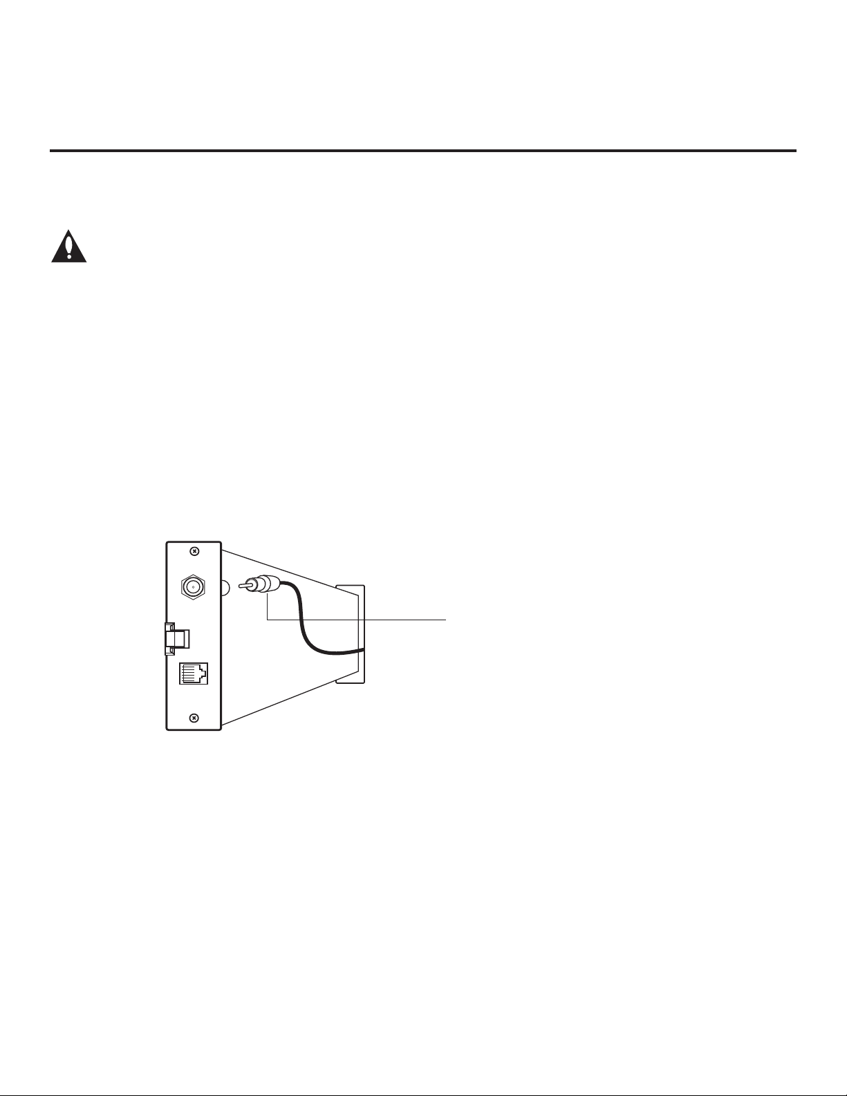
MPI Card Slot
The MPI card is equipped with an RF jack for antenna/cable signal source connection. The slot is also
available for installing a PPV card.
Note: (LG3DDH TVs only) Turn the TV On. If the Express Script Installer Menu Wizard is
present on the display (e.g., this is the first time the TV has been turned On), exit the
Express Script before inserting the PPV card.
MPI Card Removal / PPV Card Installation
1. Remove the two MPI card retainer screws.
2. Pull out the current MPI card far enough so that the RF cable can be detached from the old card.
3. Detach the RF cable.
4. Place the new PPV card into the slot and slide it in far enough to reconnect the RF cable.
5. Reconnect the RF cable.
6. Insert the card all the way into the slot making sure it is fully seated into the back plane connector.
7. Replace the two card retainer screws.
ANTENNA
/CABLE
MPI
RF CABLE
RF cable needs to be
disconnected to remove
current card.
10
206-4096

Pillow Speaker Setup
Set up pillow speaker after Commercial Mode Setup and Cloning procedures are complete.
Connect a Pillow Speaker to the LCD TV/Monitor
1. Connect the Pillow Speaker to the output jack on the
back of the TV.
2. Either:
• Slide the control switch to PILLOW SPEAKER on the
rear panel of the TV to control TV and hear audio on
pillow speaker.
• For TV speakers sound with pillow speaker control,
set the control switch to NORMAL SPEAKER.
Use a pillow speaker that is a UL recognized pendant
control bearing the warning: “Risk of fi re if used in oxygen
enriched atmosphere. Keep pendant control away from
oxygen equipment.”
Controlling the TV with Serial Data
The TV is capable of being controlled by a single-wire,
serial data signal. This is an LG patented technology and
is being implemented by certain brands of “smart” pillow
speakers.
Controlling the TV with Mechanical Switches
Pin 4 (common) is momentarily connected to pin 1, 3, or 6
via push-action switches to control Power On/Off and
Channel Up/Down. These pins are at +13 volts DC (when
measured from pin 4) with the switches open. Current
draw is 8 mA when a switch is closed. (This operation is
identical to previous models using the 5-wire interface,
except that only +7 volts DC was supplied and current
draw was only 2.5 mA.)
Pin No. Description
1 External TV On/Off switch.
2 (Not used)
3 External Channel Up switch or Data in.
4 Common connection for control, data, and audio
output. Impedance to earth ground is a 10-meg
resistor in parallel with a 1100 pf capacitor.
5 Isolated audio output. Nominal 14 ohm source
impedance with short circuit protection. Intended
for a pillow speaker with a low-impedance pad-type
volume control.
6 External Channel Down switch.
SPKR
TV
VOLUME CONTROL
TV
ON/OFF
4
5
6
1
2
PILLOW
SPEAKER
5
1
CHAN
DOWN
1
2
3
3
4
5
6
NORMAL
SPEAKER
PILLOW
SPEAKER
4
3
6
2
(MALE
PLUG)
CHAN
UP
TV ON/OFF
OPEN
CHAN UP/DATA IN
COMMON
AUDIO OUT
CHAN DOWN
SPEAKER SWITCH
206-4096
11
Installer Overview
This is the Commercial Mode Setup Guide only.
Installer Menu / Commercial Mode Setup
To set up a Master TV, you will need to know how to enter the TV
Installer Menu and make changes to the default values as required. If
necessary, familiarize yourself with the Installer Menu and how to make
and save changes. Refer to page 18 for information on accessing the
Installer Menu. Pages 18 to 23 describe Installer Menu items in detail.
Installer Remote
An LG Installer Remote similar to that shown to the right is required to
set up and operate the TV. See next page for typical key functions.
Cloning
Cloning refers to the process of capturing a Master TV Setup and transferring it to a Target TV. The Master TV’s clonable features need to be
configured as part of the Commercial Mode Setup. This is a critical step.
If the Master TV’s clonable features—channel icons or labels, digital font
options, etc.—are not set up correctly, the cloned TVs will all have problems. Pages 30 to 35 provide detailed information on cloning requirements and procedures.
HOSPITAL PTC INSTALLER MENU
000 INSTALLER SEQ 000
UPN 000-000-000-000 FPGA E0F1
PTC V1.00.000 CPU V3.06.00
Typical Installer Menu
CH
PREVIEW
INFO
POWER
GUIDE
CC
MUTE
BANK
SAP
AAA +
AAA +
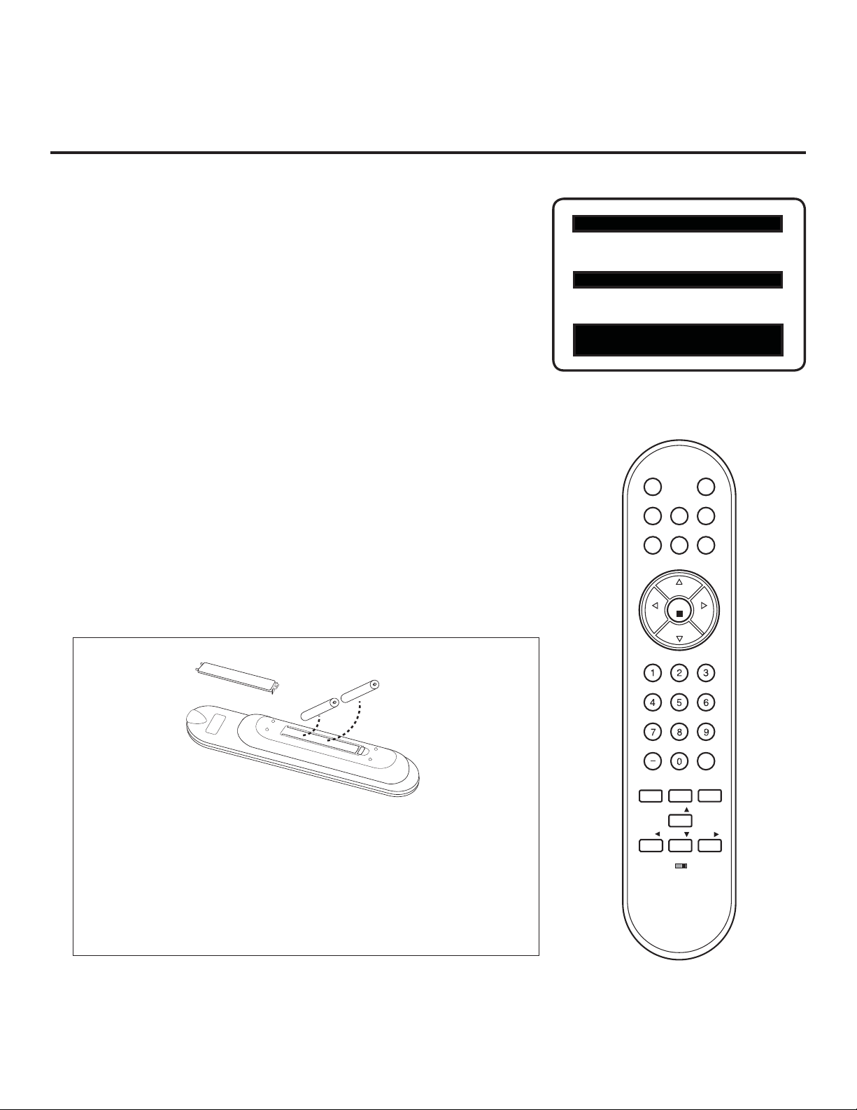
Installing Batteries in Installer
Remote
• Remove the battery compartment cover on the back side of the
remote by pressing the arrow tab forward and lifting.
• Install two high-quality alkaline 1.5V AAA batteries. Never mix old
or used batteries with new ones. Install batteries matching correct
polarity as shown (+ with + and - with -).
• Replace the battery compartment cover.
VOL
MENU
TIMER
ADJ
ADJ ADJ
BED1
CH
OK
CH
VOL
FLASHBK
ALARM
ADJ
BED2
12
206-4096
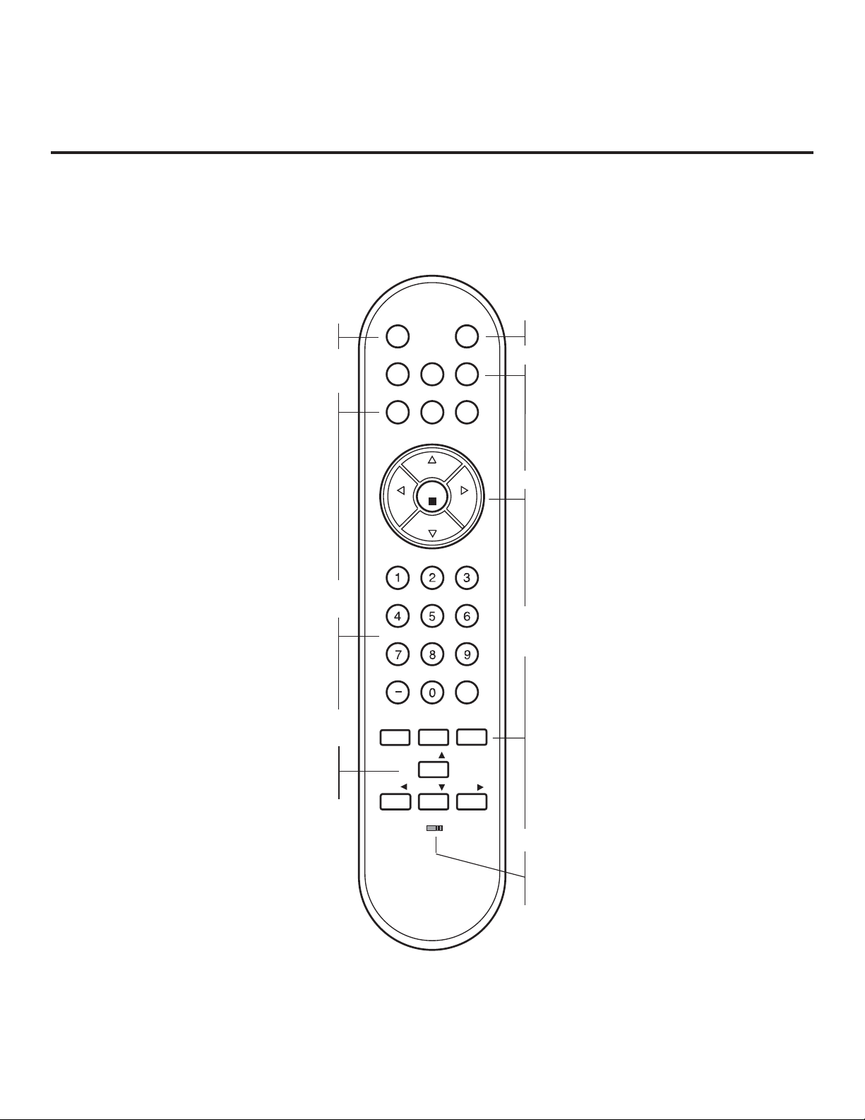
Installer Remote Control Typical Key Functions
To put the Installer Remote into TV operating mode, select TV with the MODE button.
The LG Installer Remote illustrated below and throughout this document shows typical remote control functions and is
provided for reference only. This Installer Remote may vary from your Installer Remote.
MUTE
Switches sound On or Off.
SAP *
Analog Mode: Selects MTS sound (Mono,
Stereo, or SAP). DTV Mode: Changes the audio
language, if additional languages are available.
INFO
Displays channel information. INFO feature is not
functional for Aux sources.
CC
Selects a closed caption option, unless the
Channel Banks Setup Menu is currently on the
screen, in which case this option displays the
Lock (V-Chip) Menu.
NUMBER Buttons (0 - 9) DASH
Use to enter a program number or channel. Dash
is used for sub-channel numbers such as 9-1,
9-2, etc.
FLASHBK
Returns to the previously tuned channel.
Up/Down/Left/Right Arrows
Tune to added channels in menu. Also, use to
navigate on-screen menus and adjust TV
settings.
MUTE
PREVIEW
BANK
INFO
SAP
CH
VOL
MENU
TIMER
ADJ
ADJ ADJ
BED1
CH
OK
CH
POWER
GUIDE
CC
VOL
FLASHBK
ALARM
ADJ
BED2
POWER
Turns the TV On or Off.
BANK
Selects Channel Bank 1, 2, 3, or 4.
CH PREVIEW
Displays and exits the Channel Banks Setup Menu.
GUIDE
Displays and removes the electronic program
guide.
CHANNEL UP/DOWN
Selects available channels found with Auto Tuning.
VOLUME UP/DOWN
Increases/decreases sound level.
OK (Enter)
Tunes in deleted channels in scan. Also, use to
adjust TV settings.
TIMER
Sets the amount of time before the TV
automatically turns itself Off.
MENU
Provides access to the TV setup menus on the
screen. Also, enters or exits the on-screen
menu system.
ALARM
Enables users to schedule a one-time “alarm”
event, in which the TV turns itself On at the
user-specified time.
SAP notes:
*
• SAP settings are retained with power Off/On for
individual analog channels.
• If SAP is selected and no SAP is provided, sound
may not be heard on channel.
• Each analog channel may have its own SAP setting.
• Digital channels will reset to default audio language
with a power Off/On.
206-4096
Bed Switch
Set to Bed 1 or Bed 2 as applicable (per
Installer Menu item 027 HOSPITAL MODE
setting).
13

Commercial Mode Setup for Master TV
CHANNEL
PICTURE
AUDIO
TIME
OPTION
LOCK
This section provides an overview of manual TV configuration. On LG3DDH TVs,
these steps are automated in an Express Setup Script (see pages 16 – 17).
This section describes how to set up a Master TV.
Note: It is recommended that you disconnect all Aux inputs. Under certain conditions, Auto Tuning
(Channel Search) is disabled if there is an Aux input active.
Note: If not disabled in the Installer Menu, Aux sources will appear in the channel scan between analog
and digital channels after the TV setup is transferred to the internal TV controller (Protocol Translator
Card [PTC]).
Note: If the Express Script Installer Menu Wizard is present on the display, exit the Express Script before
beginning/continuing this procedure.
1. Set Installer Menu items.
a) Use the Installer Remote to enter the TV Installer Menu: Press
MENU repeatedly until the on-screen menu locks up, and then
press 9-8-7-6 + OK (Enter). Refer to pages 18 to 23 for detailed
information on Installer Menu items.
b) Set Installer Menu item 117 FACT DEFAULT to 001 and press
OK (Enter) on the Installer Remote.
This clears all Installer Menu custom settings, channel labels/
icons, etc. and reloads the factory default settings. The value will
change back to 0 after the PTC has been restored to factory default condition. This step ensures that the TV Channel Memory will
be the active Channel List.
c) Set Installer Menu item 003 BAND/AFC, as appropriate, and
press OK (Enter).
• Broadcast: Set to 000.
• CATV: Set to 001 (default).
• HRC: Set to 002.
• IRC: Set to 003.
d) Set any other Installer Menu items that affect your TV programming
network to the required confi guration. For example, enable/disable
Aux sources, set a Start Channel, etc.
e) After you have adjusted all required Installer Menu item settings,
press OK (Enter) on the Installer Remote to exit the menu and
save your changes.
2. Set up TV features.
On-screen setup menus control the features of the TV (see page 24).
Press MENU on the Installer Remote to access the setup menus,
and then set Channel, Picture, Audio, etc. options to the desired
configurations. See also the Clonable Menu Features list on page 30.
Note: If desired, you can run Auto Tuning (see step 3) prior to
completing this step.
3. Run Auto Tuning (Channel Search).
a) Search for all available analog and digital channels: Go to the
Channel Menu, select the Auto Tuning option, and follow the
on-screen instructions.
HOSPITAL PTC INSTALLER MENU
000 INSTALLER SEQ 000
UPN 000-000-000-000 FPGA E0F1
PTC V1.00.000 CPU V3.06.00
Typical TV Installer Menu
Note: The Installer Menu header will vary
depending on the TV you are setting up.
117 FACT DEFAULT 001
003 BAND/AFC 00X
Adjust the settings for these
Installer Menu items.
Set the TV features to the desired
configuration for the end user.
(Continued on next page)
14
206-4096

Commercial Mode Setup for Master TV (Cont.)
CHANNEL
Auto Tuning
Manual Tuning
Channel Edit
Channel Label
Enter
Move
(Continued from previous page)
3. Run Auto Tuning (Channel Search). (continued)
b) Use the Channel Edit option in the Channel Menu to edit the channel
lineup, as necessary , to include free to guest channels only.
• Add/delete channels per your system requirements. Note that
physical channel numbers are used to identify virtual channels.
Also, channel numbers cannot be higher than 255.
• Use the Channel Label option in the Channel Menu to add familiar
channel trademarks/logos such as ABC, CBS, NBC, etc. to the
Channel-Time on-screen display. Identifi able labels (logos) should
enable the end user to readily know what common networks are
available. (You can add the channel labels in this step, or you can
add channel logos or labels for channels without icons in step 5.)
4. Transfer the TV Setup to the internal TV Controller (PTC):
2-5-5 + MENU Mode
After the TV channel lineup has been edited and channel label icons
added, enter the Installer Menu. Once in the Installer Menu, press
2-5-5 + MENU on the Installer Remote to initiate the transfer of the
Master TV Setup to the PTC. Once the transfer is complete, the TV
will exit the Installer Menu.
Note: The maximum number of active channels and Aux sources that
can be transferred is 141. Total channels numbering more than 141 will
result in erratic TV operation.
Note: Scan Mode is not functional until the TV setup is transferred.
5. Add Custom Channel and Aux Source Labels for Analog
Channels: 2-5-4 + MENU Mode
Enter the Installer Menu, and press 2-5-4 + MENU on the Installer
Remote. Add/edit custom text labels to channel on-screen displays.
Note that digital channels often have a broadcaster generated label
(see 2-5-4 + MENU procedural information on page 25). When you
are finished, press MENU to exit 2-5-4 + MENU Mode.
6. Verify the TV setup.
At this point, verify that the channel lineup, channel icons, and custom labels
are correct. Make sure the TV features are set per your requirements.
7. Set up channel banks.
Set up channel banks, as desired (see pages 26 to 29).
Note: When you lock the channel lineup (see next step), the Channel Banks
Setup Menu is no longer accessible via the Installer Remote. If you wish to set
up channel banks at a later time, you will need to set Installer Menu item 028
CH. OVERIDE to 001 to enable access to the Channel Banks Setup Menu.
8. (Recommended) Lock the channel lineup.
Enter the Installer Menu, and set item 028 CH. OVERIDE to 000 to lock the
channel lineup and restrict access to the TV setup menus.* Press OK (Enter)
to exit the Installer Menu and save your changes.
The Master TV Setup is now ready to be copied to a clone programmer (see
cloning information in this document).
Run Auto Tuning, edit channels, and select
familiar channel trademarks/logos using
Channel Menu options.
DIGITAL 19-3
STEREO SAP
MONO
WXYZ
Custom Text Label “WXYZ” created in
2-5-4 + MENU (Add Channel Label) Mode.
028 CH. OVERIDE 000
After verifying the TV Setup, set Installer
Menu item 028 CH. OVERIDE to 000.*
* This step prevents end users from access-
ing channel settings (i.e., the Channel Menu
will be inaccessible/grayed out).
206-4096
15
 Loading...