

LG 26LG3000, 22LG3000, 22LG3010, 19LG3000, 19LG3010 Owner's Manual
LCD TV
OWNER’S MANUAL
ENGLISH
Trade Mark of the DVB Digital Video
Broadcasting Project (1991 to 1996)
ID Number(s): 5661 : 19LG3000-ZA
5662 : 22LG3000-ZA
5663 : 26LG3000-ZA
5724 : 19LG3010-ZB
5745 : 22LG3010-ZB
LCD TV MODELS
19LG30**
22LG30**
26LG30**
Please read this manual carefully before operating
your TV.
Retain it for future reference.
Record model number and serial number of the
TV.
Refer to the label on the back cover and quote this
information to your dealer when requiring service.
1

ACCESSORIES
x3
x4
Ensure that the following accessories are included with your TV. If an accessory is missing, please contact the
dealer where you purchased the TV.
■
Images shown may differ from your TV
Owner’s Manual
Protection Cover
(19/22LG30**)
Only 19/22LG30**
Remote Control
or
Protection Cover
(26LG30**)
Batteries
Power Cord
This feature is not available for all models
Polishing Cloth
Polishing cloth for use on the screen.
Lightly wipe any stains or ngerprints on the surface of
the TV with the polishing cloth.
Do not use excessive force. This may cause
scratching or discolouration.
2
Cable management clip
Only 26LG30**
Bolts for stand assembly
(Refer to p.9)
1-screw for stand xing
(Refer to p.6)

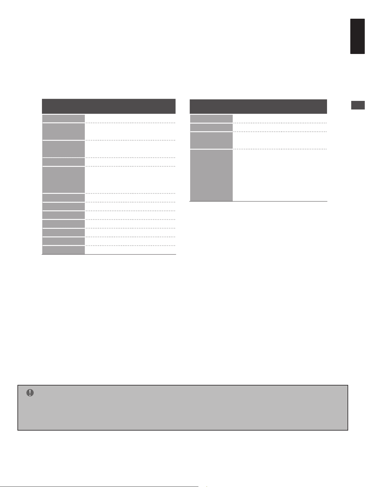
Contents
3
ENGLISH
ACCESSORIES....................................................2
SAFETY INSTRUCTIONS/WARNING .................5
PREPARATION
Front Panel Controls.............................................6
Back Panel Information ........................................8
Setting Up Your TV .............................................10
Positioning Your Display .....................................12
Kensington Security System...............................12
Antenna Connection ...........................................15
EXTERNAL EQUIPMENT SETUP
HD Receiver Setup .............................................16
Digital Audio Out Setup ......................................17
DVD Setup..........................................................18
VCR Setup..........................................................20
Insertion Of CI Module .......................................23
PC Setup ............................................................23
Connecting with a HDMI to DVI cable ............24
Auto Congure (RGB [PC] mode only) ...........26
Adjustment for screen Position, Size, Phase .27
Selecting Resolution .......................................28
WATCHING TV / PROGRAMME
CONTROL
Remote Control Key Functions ..........................29
Turning On The TV .............................................31
Programme Selection .........................................31
Volume Adjustment .............................................31
Menus Selection And Adjustment .......................32
Auto Programme Tuning.....................................33
Language Selection (In Digital Mode Only) ........34
Manual Programme Tuning (In Digital Mode) .....36
Manual Programme Tuning (In Analog Mode) ....37
Programme Skip .................................................38
Programme Swap ...............................................39
Assigning Programme Fine Tune (In Analog Mode)
40
Input List .............................................................42
EPG (Electronic Programme Guide) (In Digital Mode)
43
Switch on/off EPG ..............................................43
Select a programme ...........................................43
Button Function in Guide Mode ..........................44
PICTURE CONTROL
Picture Size (Aspect Ratio) Control ....................45
Preset Picture Settings .......................................47
Picture Mode-Preset .......................................47
Colour Temperature (Medium/Warm/Cool) .....48
Manual Picture Adjustment .................................49
Picture Mode-User option ...............................49
Picture Improvement Technology .......................50
AV Mode .............................................................51
SOUND CONTROL
Sound Setting Adjustment -User Mode ..............52
Preset Sound Settings-Audio Mode ...................53
Balance...............................................................54
Virtual Surround ..................................................55
Auto Volume Leveler ..........................................56
Selecting Digital Audio Out .................................57
TV Speakers On/ Off Setup ................................58
Type ....................................................................59
OPTION CONTROL
Menu Language Selection ..................................60
Time Zone Setup ................................................61
Clock Setup ........................................................62
Auto On/Off Timer Setting ..................................63
Sleep Timer Setting ............................................64
Subtitle................................................................65
Teletext Language ..............................................66
Diagnostics .........................................................67
CI (Common Interface) Information ....................68
Contents

PARENTAL CONTROL / RATINGS
4
Set Password & Lock System ............................69
Block Programme ...............................................70
Parental Guidence ..............................................71
Key Lock .............................................................72
TELETEXT
Switch On/Off .....................................................73
Contents
Simple Text .........................................................73
Top Text ..............................................................73
Special Teletext Functions ..................................74
DIGITAL TELETEXT
Teletext Within Digital Service ............................75
Teletext In Digital Service ...................................75
APPENDIX
Initializing (Reset to original factory settings) .....76
Troubleshooting ..................................................77
Maintenance .......................................................79
Product Specications ........................................80

SAFETY INSTRUCTIONS/WARNING
- Apparatus shall not be exposed to dripping or splashing and no objects lled with liquids, such
as vases, shall be placed on the apparatus.
- The Class I apparatus shall be connected to a mains socket outlet with a protective earthing
connection.
ENGLISH
- The mains plug or appliance coupler is used as the disconnect device, the disconnect device
shall remain readily operable.
- Excessive sound pressure from earphones and headphones can cause hearing loss. Adjustment of the equalizer to maximum increases the earphones and headphones output voltage and
therefore the sound pressure level.
- A certied power supply cord has to be used with this equipment. The relevant national installa-
tion and/or equipment regulations shall be considered. A certied power supply cord not lighter
than ordinary polyvinyl chloride exible cord according to IEC 60227 (designation H05VV-F 3G
0.75mm2 or H05VVH2-F2 3G 0.75mm2) shall be used. Alternative a exible cord be of synthetic
rubber according to IEC 60245 (designation H05RR-F 3G 0.75mm2) shall be used.
- The LCD TV Monitor is for entertainment use only and visual display tasks are excluded
SAFETY INSTRUCTIONS/WARNING
5
PREPARATION
6
PREPARATION
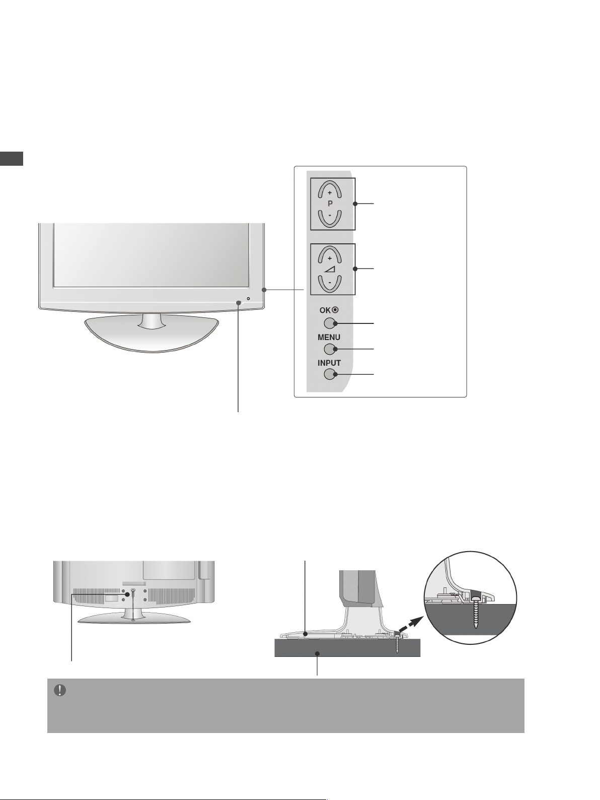
Front Panel Controls
■
Image shown may differ from your TV.
■
If your TV has a protection lm attached, remove the lm and then wipe the TV with a polishing cloth.
LCD TV Models : (Only 26LG30**)
PROGRAMME
VOLUME
OK
MENU
POWER
Remote Control Sensor
Power/Standby Indicator
Illuminates red in standby mode.
Illuminates blue when the TV is switched on.
INPUT
Attaching the TV to a desk (Only 26LG30**)
The TV must be attached to desk so it cannot be pulled in a forward/backward direction, potentially causing injury or
damaging the product. Use only an attached screw.
Stand
1-Screw
(provided as parts of the product)
Desk
WARNING
To prevent TV from falling over, the TV should be securely attached to the oor/wall per installation
►
instructions. Tipping, shaking, or rocking the machine may cause injury.

LCD TV Models : (Only 19/22LG30**)
INPUT MENU OK - + - +
PROGRAMMEVOLUME
MENU
OK
INPUT
7
ENGLISH
PREPARATION
POWER
Remote Control Sensor
Power/Standby Indicator
Illuminates red in standby mode.
Illuminates blue when the TV is switched on.

PREPARATION
RGB IN
(PC)
OPTICAL
DIGITAL
AUDIOOUT
AV 1 AV 2
ANTENNA IN
RS-232C IN
(SERVICE ONLY)
AUDIO IN
(RGB/DVI)
HDMI IN 1
(DVI)
COMPONEN T IN
VIDEO
AUDIO
AV IN 3
H/P
S-VIDEO
HDMI IN 2 PCMCIA CARD SLOT
R L
AUDIO
VIDEO
10
11
12
5
4
1
2 3
5 6 7 8 9
8
PREPARATION
Back Panel Information
1Power Cord Socket
This TV operates on an AC power. The voltage is
indicated on the Specications page. Never attempt
to operate the TV on DC power.
2RGB/DVI Audio Input
Connect the audio from a PC or DVI.
3DIGITAL AUDIO OUT OPTICAL
Connect digital audio from various types of equipment.
Note: In standby mode, this port does not work.
4Euro Scart Socket (AV1/AV2)
Connect scart socket input or output from an external
device to these jacks.
5HDMI Input
Connect a HDMI signal to HDMI IN. Or DVI (VIDEO)
signal to HDMI/DVI port with DVI to HDMI cable.
6RGB Input
Connect the output from a PC.
7RS-232C IN (SERVICE ONLY) PORT
8Component Input
Connect a component video/audio device to
these jacks.
9Antenna Input
Connect RF antenna to this jack.
PCMCIA (Personal Computer Memory Card
International Association) Card Slot
(This feature is not available in all countries.)
Audio/Video Input
Connect audio/video output from an external
device to these jacks.
S-Video Input
Connect S-Video out from an S-Video device.
Headphone Socket
Connect the headphone plug to this socket.
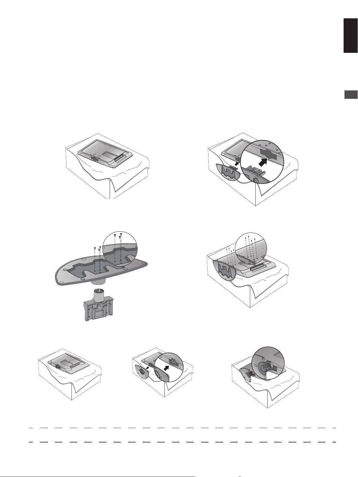
Stand Installation
9
ENGLISH
PREPARATION
When assembling the desk type stand, check whether the bolt is fully tightened. (If not tightened fully, the product
can tilt forward after the product installation.) If you tighten the bolt with excessive force, the bolt can deviate from
abrasion of the tightening part of the bolt.
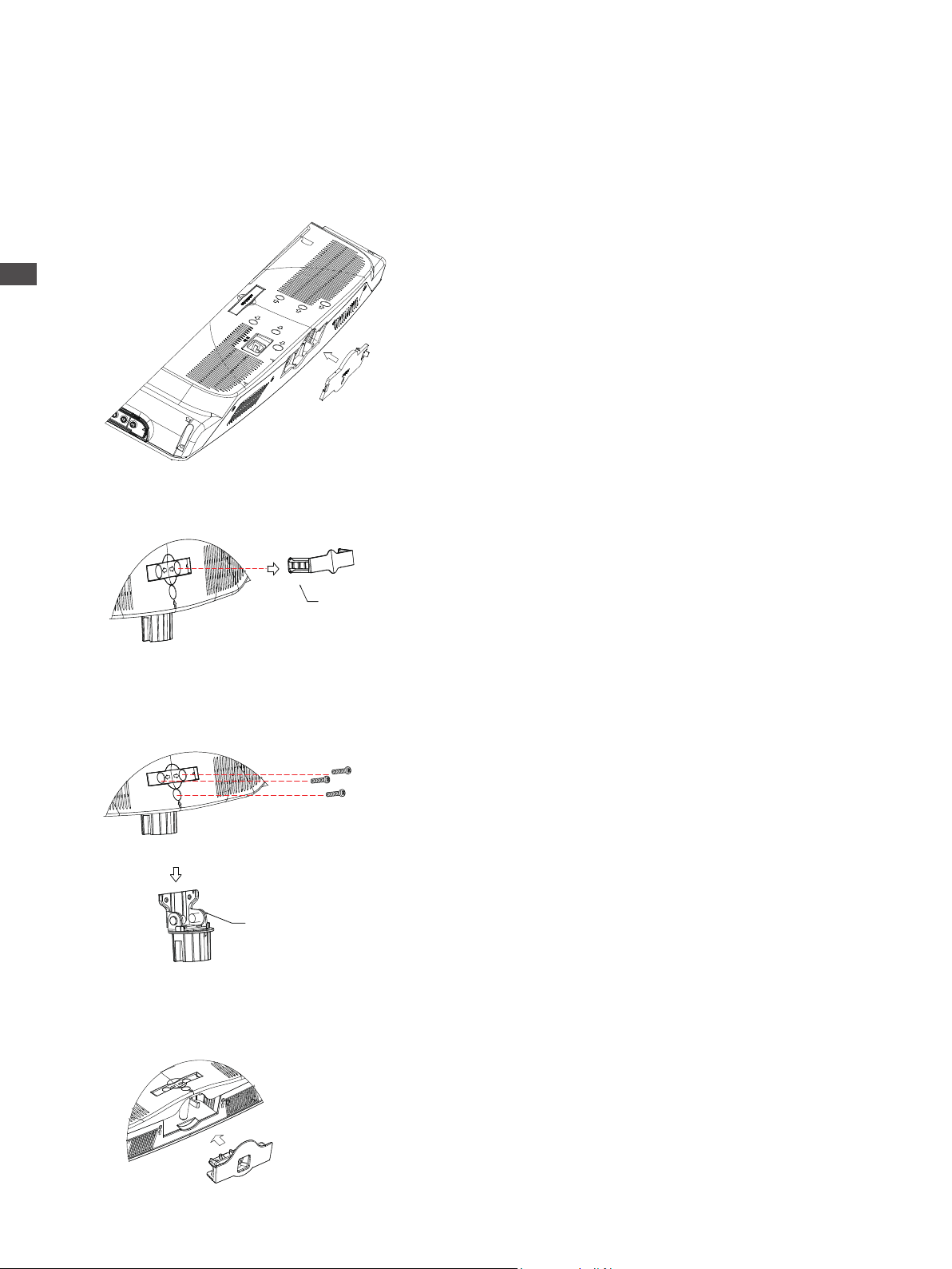
(Only 26LG30**)
Carefully place the TV screen side down on a
cushioned surface to protect the screen from
damage.
Assemble the parts of the Stand Body with
the Cover Base of the TV.
Cover Base
Assemble the TV as shown.
Fix the 4 bolts securely using the holes in
the back of the TV.
(Only 19/22LG30**)
Carefully place the TV screen side down on a cushioned surface to protect the screen from damage.
Assemble the TV as shown.
Stand Body

PREPARATION
10
PREPARATION
Setting Up Your TV
Please set it up carefully so the product does not fall over.
■ You should purchase necessary components to x the TV to the wall.
■ Position the TV close to the wall to avoid the possibility of falling.
■ The instructions shown below are a safer way to set up the TV, which is to x it to the wall, avoiding the possibility
of it falling forwards if pulled. This will prevent the TV from falling forward and causing injury. This will also prevent
the TV from damage. Ensure that children do not climb or hang from the TV.
Use the eye-bolts or TV brackets/bolts to x the TV to the wall as shown in the picture.
(If your TV has bolts in the holes, loosen these bolts.)
* Fix the eye-bolts or TV brackets/bolts and tighten them securely in the upper holes.
Secure the wall brackets with the bolts on the wall. Match the height of the bracket that is mounted on the
wall.
Use a sturdy rope to tie the TV. It is safer to tie the rope horizontally between the wall and the TV.
NOTE
When moving the TV, untied the rope rst.
Use a platform or cabinet strong and large enough to support the size and weight of the TV.
To set up TV safely, make sure that the height of the bracket on the wall and on the TV are the same.
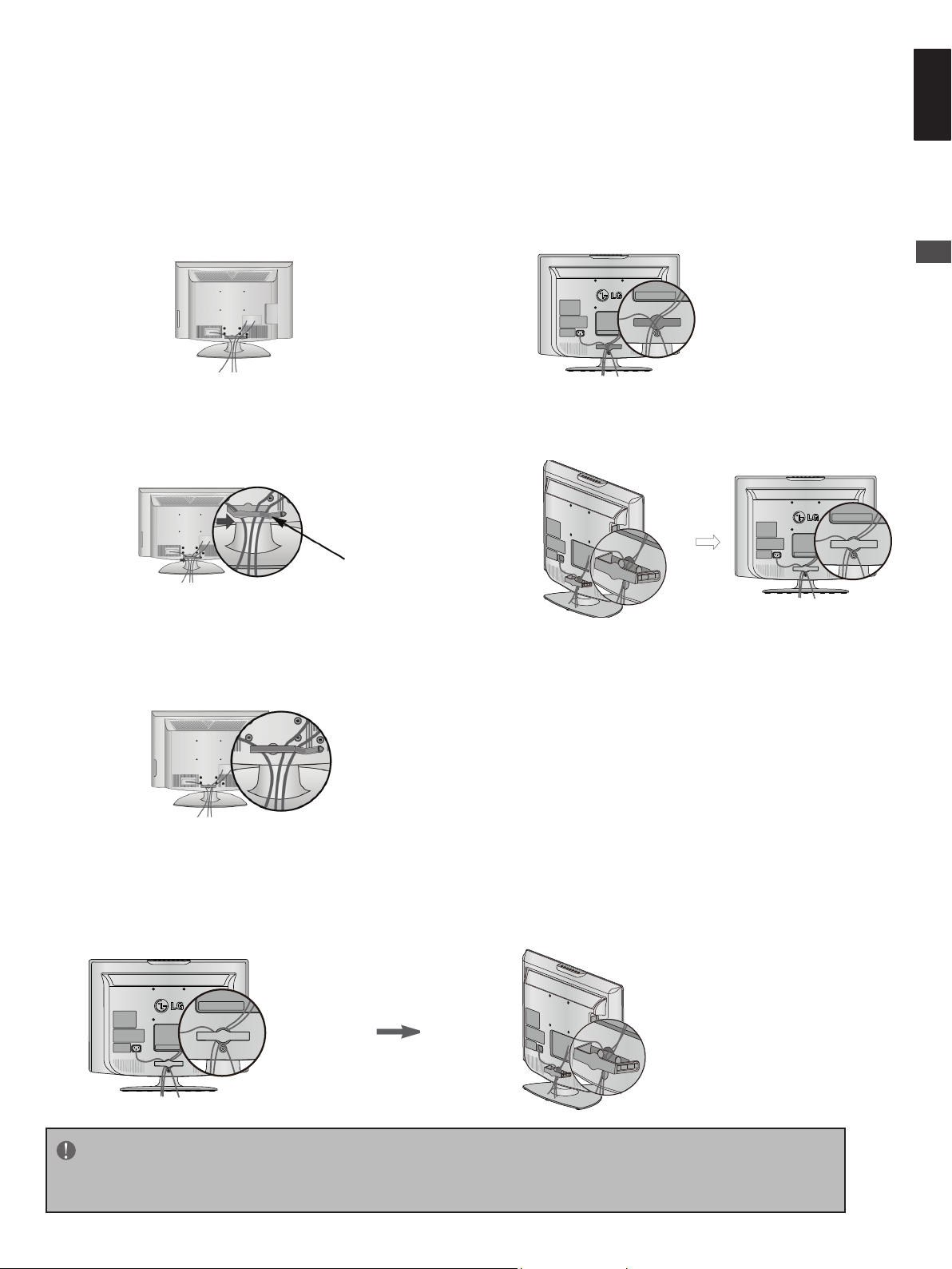
Back Cover for Wire Arrangement
11
ENGLISH
PREPARATION
26LG30** 19/22LG30**
Connect the cables as necessary.
Open the CABLE MANAGEMENT CLIP as
shown and manage the cables.
CABLE
MANAGEMENT
CLIP
Fit the CABLE MANAGEMENT CLIP as
shown.
Connect the cables as necessary.
To connect additional equipment, see the External
Equipment Setup section.
Install the CABLE MANAGEMENT CLIP as shown.
How to remove the cable management clip (for 19/22LG30**)
First, press the cable management. Hold the CABLE MANAGEMENT CLIP with both hands and pull it backward.
NOTE
Do not use the CABLE MANAGEMENT CLIP to lift the TV.
- If the TV is dropped, you may be injured or the TV may be damaged.
PREPARATION
12
PREPARATION
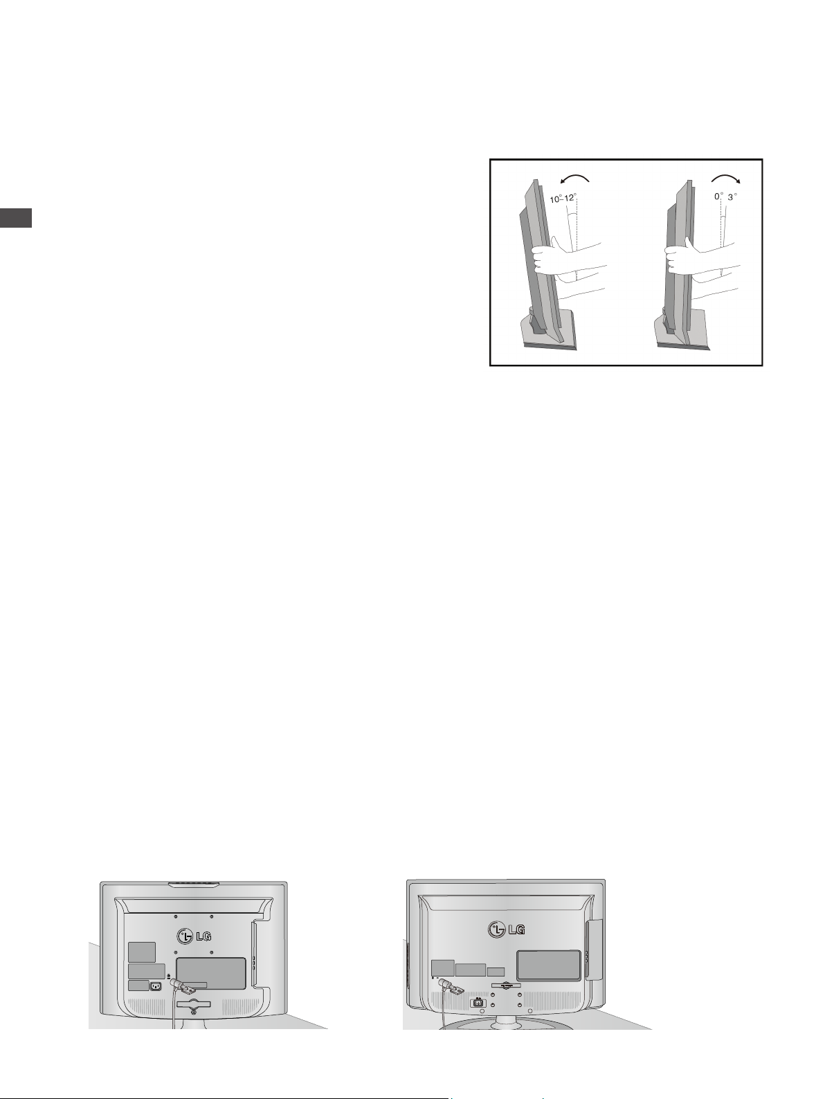
Positioning Your Display
(Only 19/22LG30**)
■
Image shown may differ from your TV.
■
Adjust the position of the panel in various ways for maximum
comfort.
• Tilt range
Location
Position your TV so that no bright light or sunlight falls directly onto the screen. Care should be taken not to expose
the TV to any unnecessary vibration, moisture, dust or heat. Also ensure that the TV is placed in a position to allow a
free ow of air. Do not cover the ventilation openings on the back cover.
If you intend to mount the TV to a wall, attach VESA standard mounting interface (optional parts) to the back of the
TV.
When you install the TV to use the wall mounting bracket (optional parts), x it carefully so as not to drop.
(Only 19/22LG30**)
Kensington Security System
The TV is equipped with a Kensington Security System connector on the back panel. Connect the Kensington
Security System cable as shown below.
For the detailed installation and use of the Kensington Security System, refer to the user’s guide provided with the
Kensington Security System.
For further information, contact http://www.kensington.com, the internet homepage of the Kensington company.
Kensington sells security systems for expensive electronic equipment such as notebook, PCs and LCD projectors.
NOTE
- The Kensington Security System is an optional accessory.
NOTES
a. It is normal if you turned on the TV with small “icker” on the screen under the low temperature.
b. Some small dots may be visible on the screen, appearing as tiny red, green, or blue spots. However, they have no
adverse effect on the monitor’s performance.
c. Avoid touching the LCD screen or holding your nger(s) against it for long periods of time.
Doing so may cauce some temporary distortion effects on the screen.
Only 19/22LG30**
Only 26LG30**

EARTHING
4 inches
4 inches
4 inches
4 inches
4 inches
4 inches
4 inches
4 inches
4 inches
13
ENGLISH
PREPARATION
Ensure that you connect the earth wire to prevent possible electric
shock. If grounding methods are not possible, have a qualied
electrician install a separate circuit breaker.
Do not try to earth the TV by connecting it to telephone wires,
lightening rods or gas pipes.
Desktop Pedestal Installation
For adequate ventilation, allow a clearance of 4” (10cm) all around the TV.
Power Supply
Circuit
breaker
Wall Mount: Horizontal Installation
For adequate ventilation, allow a clearance of 4” (10cm) all around the TV. Detailed installation
instructions are available from your dealer, see the optional Tilt Wall Mounting Bracket Installation and
Setup Guide.
WARNING
Wall mounting of the TV should only be performed by qualied installers. Only use
the supplied components to secure the VESA-compatible wall bracket to your TV. The
supplied components are designed to match the weight of your TV.
- Information for wall mount (especially screw size)
To attach a wall mount bracket to your TV:
1. Remove the four M4 screws holding your TV to the stand.
2. Secure the wall mount bracket to the back of your TV using four M4 screws.
PREPARATION
14
When not using the desk-type stand.
(26LG30**)
When installing the wall-mounted unit, use the protection cover for desk-type stand installation.
Insert the PROTECTION COVER into the TV until clicking sound is produced.
EXTERNAL EQUIPMENT SETUP
(Only 19/22LG30**)
When installing the wall-mounted unit, please follow the installation steps as in the pictures below.
CABLE MANAGEMENT
HINGE ASSEMBLY
Step 1: Pull out the CABLE MANAGEMENT.
Step 2: Unscrew these 3 screws.
Step 3: Take out the HINGE ASSEMBLY.
Step 4: Insert the PROTECTION COVER into the TV.

ANTENNA IN
ANTENNA IN
Step 5: Attach the 3 screws that were removed in step 2.
15
ENGLISH
■ To prevent damages, do not connect to the mains outlet until all connections are made between the devices.
Antenna Connection
■ For optimum picture quality, adjust antenna direction.
■ An antenna cable and converter are not supplied.
PREPARATION
Multi-family Dwellings/Apartments
Wall
(Connect to wall antenna socket)
Antenna
Socket
RF Coaxial Wire (75 ohm)
Outdoor
Antenna
(VHF, UHF)
Single-family Dwellings /Houses
(Connect to wall jack for outdoor antenna)
UHF
Antenna
Signal
Amplier
VHF
■ In poor signal areas, to achieve better picture quality, it may be necessary to install a signal amplier to the antenna
as shown above.
■ If signal needs to be split for two TVs, use an antenna signal splitter for connection.
EXTERNAL EQUIPMENT SETUP
COMPON ENT IN
VIDEO
AUDIO
HDMI IN 1
(DVI)
16
EXTERNAL EQUIPMENT SETUP
■ To avoid damaging any equipment, never plug in any power cords until you have nished connecting all equipment.
HD Receiver Setup
■ This TV can receive Digital RF/Cable signals without an external digital set-top box. However, if you do receive
digital signals from a digital set-top box or other digital external device, refer to the diagram as shown below.
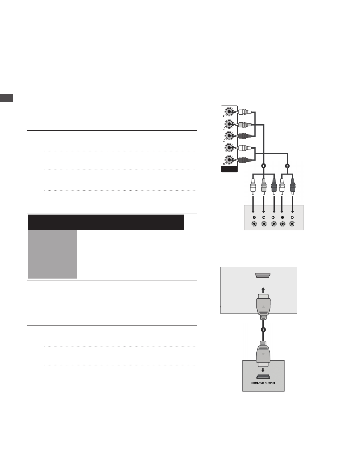
Connecting with a component cable
Connect the video outputs (Y, PB, PR) of the digital set-top
box to the COMPONENT IN VIDEO jacks on the TV.
Connect the audio output of the digital set-top box to the
COMPONENT IN AUDIO jacks on the TV.
Turn on the digital set-top box.
(Refer to the owner’s manual for the digital set-top box.)
Select Component input source using the INPUT button on
the remote control.
Signal Component HDMI
480i Yes No
576i Yes Yes
480p/576p Yes Yes
720p/1080i Yes Yes
1080p Yes Yes
Connecting a set-top box with an HDMI cable
Connect the HDMI output of the digital set-top box to the
HDMI IN1(DVI) or HDMI IN 2 jack on the TV.
Turn on the digital set-top box.
(Refer to the owner’s manual for the digital set-top box.)
Select HDMI1 or HDMI2 input source using the INPUT
button on the remote control.
EXTERNAL EQUIPMENT SETUP
AUDIO IN
(RGB/DVI)
HDMI IN 1
(DVI)
RGB IN
(PC)
AV 1 AV 2
RS-232C IN
(SERVICE ONLY)
AUDIO IN
(RGB/DVI)
COMPONENT IN
VIDEO
AUDIO
OPTICAL
DIGITAL
AUDIOOUT
1
17
ENGLISH
EXTERNAL EQUIPMENT SETUP
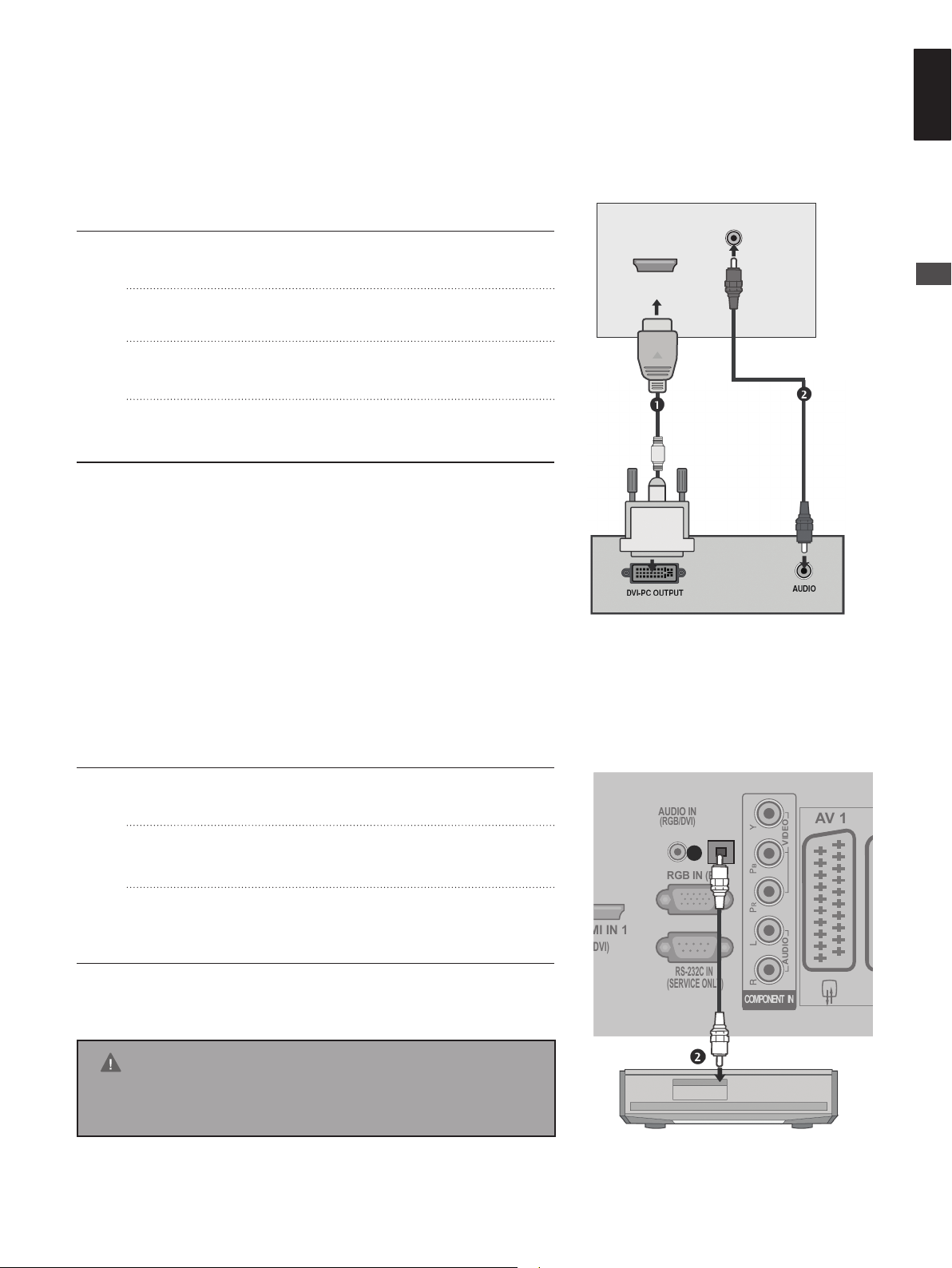
Connecting with a HDMI to DVI cable
Connect the digital set-top box to HDMI IN 1(DVI) jack on
the TV.
Connect the audio output of the digital set-top box to the
AUDIO IN (RGB/DVI) jack on the TV.
Turn on the digital set-top box. (Refer to the owner’s manual
for the digital set-top box.)
Select HDMI1 input source using the INPUT button on the
remote control.
Digital Audio Out Setup
- Sending the TV’s audio signal to external audio equipment via the Digital Audio Output (Optical) port.
Connect one end of an optical cable to the TV Digital Audio
(Optical) Output port.
Connect the other end of the optical cable to the digital
audio (optical) input on the audio equipment.
Set the “ TV Speaker option - Off ” in the AUDIO menu.
(► p.58) Refer to the external audio equipment instruction
manual for operation.
CAUTION
Do not look into the optical output port. Looking at the laser
beam may damage your vision.

DVD Setup
COMPO NENT IN
VIDEO
AUDIO
18
EXTERNAL EQUIPMENT SETUP
When connecting with a component cable
Component Input ports
To achieve better picture quality, connect a DVD player to the component input ports as shown
below.
Component ports on the TV Y Pb Pr
Video output ports on DVD
Connect the video outputs (Y, Pb, Pr) of the DVD to the
COMPONENT IN VIDEO jacks on the TV.
Connect the audio outputs of the DVD to the
COMPONENT IN AUDIO jacks on the TV.
Turn on the DVD player, insert a DVD.
Select Component input source using the INPUT button
on the remote control.
Refer to the DVD player’s manual for operating
instructions.
player
Y Pb Pr
Y B-Y R-Y
Y Cb Cr
Y Pb Pr
Connecting with a Euro Scart cable
Connect the Euro scart socket of the DVD to the AV1 Euro
scart socket on the TV.
Turn on the DVD player, insert a DVD.
Select AV1 input source using the INPUT button on the
remote control.
If connected to AV2 Euro scart socket, select AV2 input
source.
Refer to the DVD player’s manual for operating
instructions.
NOTE
Any Euro scart cable used must be signal shielded.
EXTERNAL EQUIPMENT SETUP
AV IN 3
H/P
S-VIDEO
HDMI IN 2 PCMCIA CARD SLOT
VIDEO
R L
AUDIO
HDMI IN 1
(DVI)
19
ENGLISH
EXTERNAL EQUIPMENT SETUP
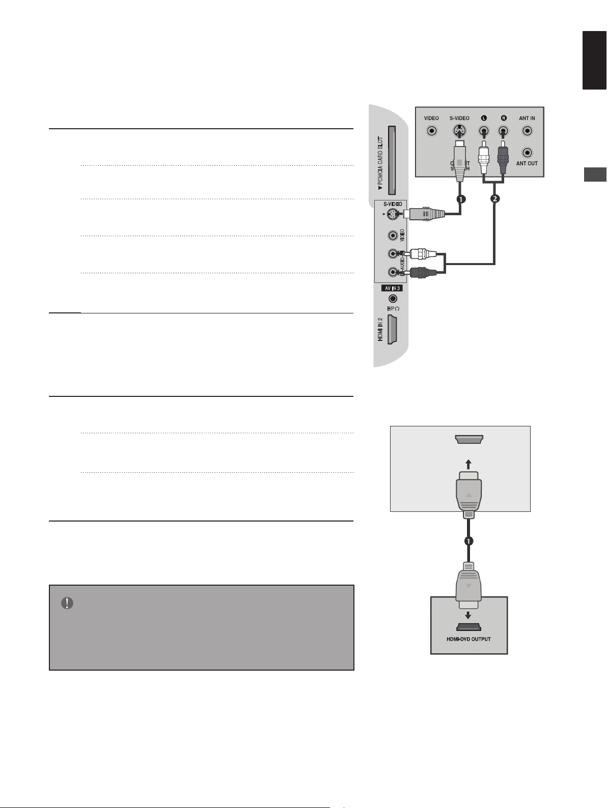
Connecting with a S-Video cable
Connect the S-VIDEO output of the DVD to the S-VIDEO
input on the TV.
Connect the audio outputs of the DVD to the AUDIO input
jacks on the TV.
Turn on the DVD player, insert a DVD.
Select AV3 (S-Video) input source using the INPUT button
on the remote control.
Refer to the DVD player’s manual for operating
Instructions.
Connecting the HDMI cable
Connect the HDMI output of the DVD to the HDMI IN
1(DVI) or HDMI IN 2 jack on the TV.
Select HDMI1 or HDMI2 input source using the INPUT
button on the remote control.
Refer to the DVD player’s manual for operating
instructions.
NOTE
The TV can receive video and audio signals simultaneously
when using a HDMI cable.
If the DVD does not support Auto HDMI, you must set the
output resolution appropriately.
VCR Setup
ANTENNA IN
20
EXTERNAL EQUIPMENT SETUP
■ To avoid picture noise (interference), allow adequate distance between the VCR and TV.
■ If 4:3 picture format is used for an extended period, the xed images on the sides of the screen may remain visible.
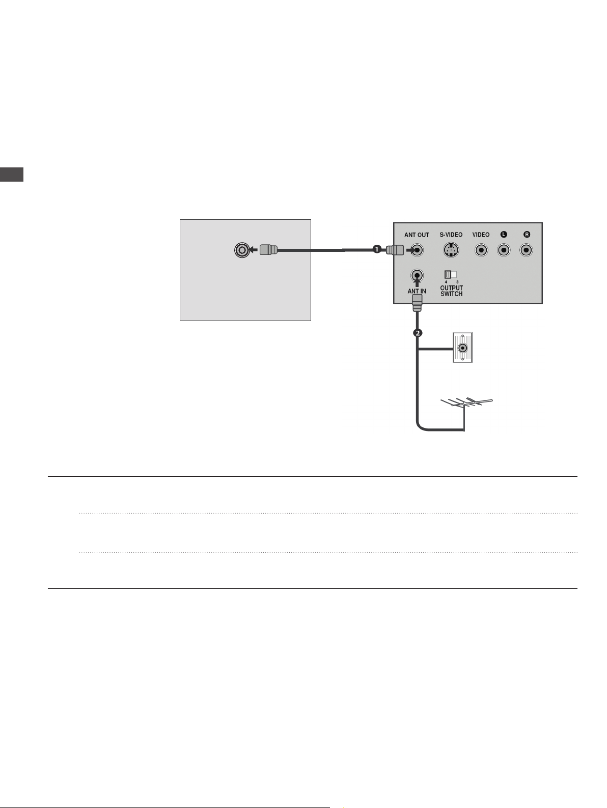
Connecting with a RF cable
Wall Jack
Antenna
Connect the ANT OUT socket of the VCR to the ANTENNA IN socket on the TV.
Connect the antenna cable to the ANT IN socket of the VCR.
Press the PLAY button on the VCR and match the appropriate channel between the TV and VCR for viewing.

EXTERNAL EQUIPMENT SETUP
AV IN 3
H/P
S-VIDEO
HDMI IN 2 PCMCIA CARD SLOT
VIDEO
R L
AUDIO
21
ENGLISH
EXTERNAL EQUIPMENT SETUP
Connecting with a Euro Scart cable
Connect the Euro scart socket of the VCR to the AV1 Euro
scart socket on the TV.
Insert a video tape into the VCR and press PLAY on the
VCR. (Refer to the VCR owner’s manual.)
Select AV1 input source using the INPUT button on the
remote control.
If connected to AV2 Euro scart socket, select AV2 input
source.
NOTE
Any Euro scart cable used must be signal shielded.
Connecting with a RCA cable
Connect the AUDIO/VIDEO jacks between TV and VCR.
Match the jack colours (Video = yellow, Audio Left = white,
and Audio Right = red)
Insert a video tape into the VCR and press PLAY on the
VCR. (Refer to the VCR owner’s manual.)
Select AV3 (CVBS) input source using the INPUT button on
the remote control.
Connecting with a S-Video cable
AV IN 3
H/P
S-VIDEO
HDMI IN 2 PCMCIA CARD SLOT
VIDEO
R L
AUDIO
AV IN 3
H/P
S-VIDEO
HDMI IN 2 PCMCIA CARD SLOT
VIDEO
R L
AUDIO
22
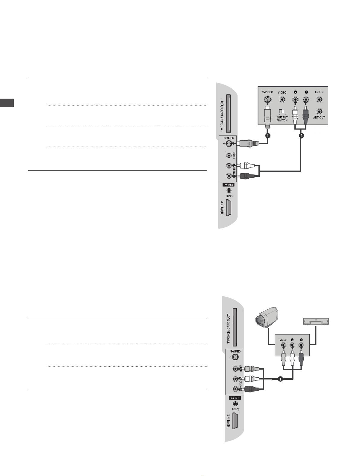
EXTERNAL EQUIPMENT SETUP
Connect the S-VIDEO output of the VCR to the S - VIDEO
input on the TV. The picture quality is improved; compared
to normal composite (RCA cable) input.
Connect the audio outputs of the VCR to the AUDIO input
jacks on the TV.
Insert a video tape into the VCR and press PLAY on the
VCR. (Refer to the VCR owner’s manual.)
Select AV3 (S-Video) input source using the INPUT button
on the remote control.
Other A/V Source Setup
Camcorder
Video Game Set
Connect the AUDIO/VIDEO jacks between TV and external
equipment. Match the jack colours. (Video = yellow, Audio
Left = white, and Audio Right = red)
Select AV3 (CVBS) input source using the INPUT button on
the remote control.
Operate the corresponding external equipment. Refer to
external equipment operating guide.
EXTERNAL EQUIPMENT SETUP
PCMCIA CARD SLOT
1
RGB IN
(PC)
AUDIO IN
(RGB/DVI)
23
ENGLISH
EXTERNAL EQUIPMENT SETUP
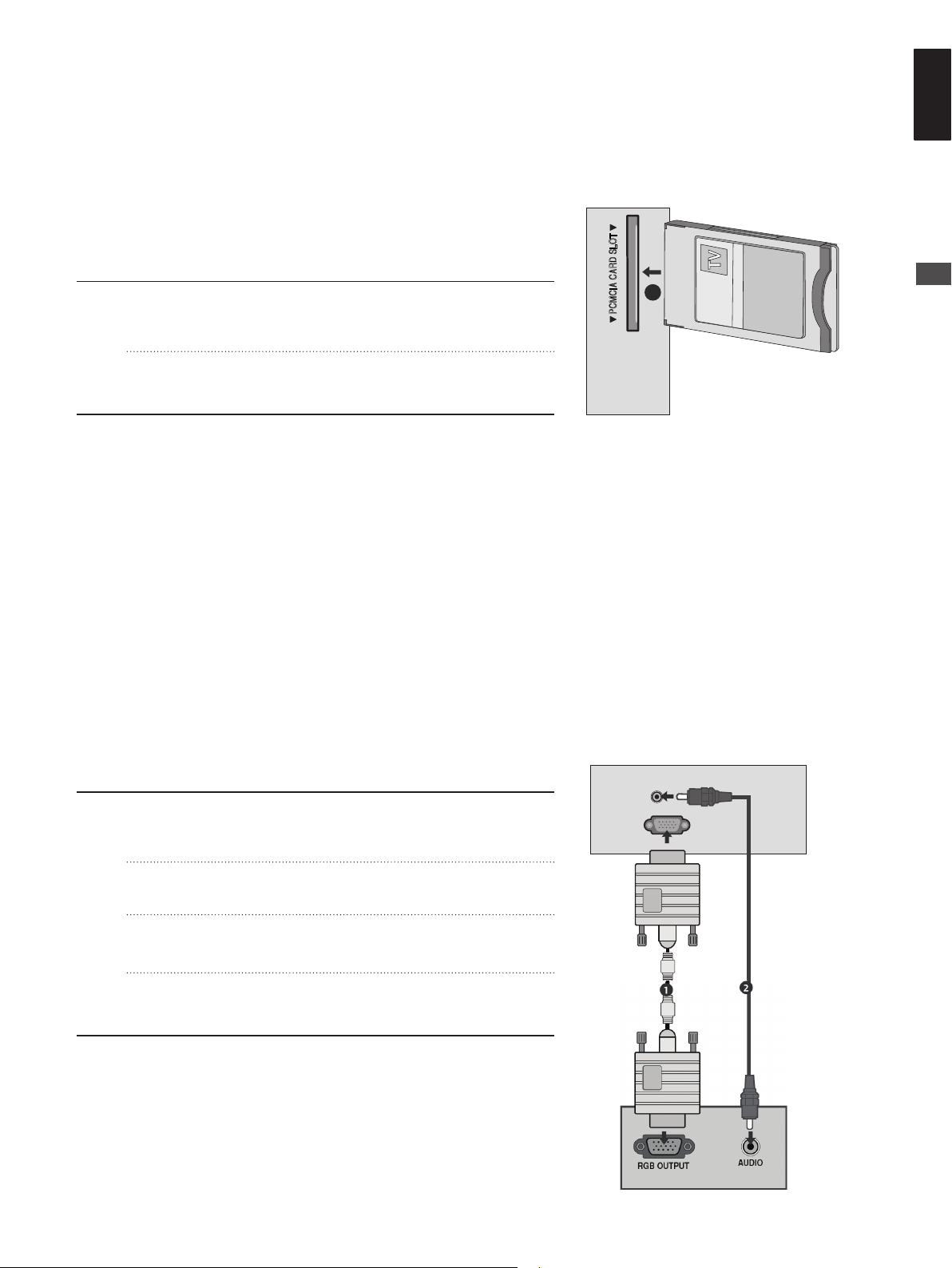
Insertion Of CI Module
- To view the encrypted (pay) services in digital TV mode.
- This feature is not available in all countries.
Insert the CI Module to PCMCIA (Personal Computer
Memory Card International Association) CARD SLOT of
TV as shown.
For further information, see p.67.
PC Setup
This TV provides Plug and Play capability, meaning that the PC adjusts automatically to the TV’s settings.
Connecting with a D-sub 15 pin cable
Connect the RGB output of the PC to the RGB IN
(PC) jack on the TV.
Connect the PC audio output to the AUDIO IN
(RGB/DVI) jack on the TV.
Turn on the PC and the TV
Select RGB input source using the INPUT button on
the remote control.

Connecting with a HDMI to DVI cable
AUDIO IN
(RGB/DVI)
HDMI IN 1
(DVI)
24
EXTERNAL EQUIPMENT SETUP
To enjoy vivid picture and sound, connect a PC to
the TV.
Avoid keeping a xed image on the TV’s screen for
prolonged periods of time. The xed image may
become permanently imprinted on the screen; use a
screen saver when possible.
Connect the PC to the RGB (PC) or HDMI IN (or
HDMI/DVI IN) port of the TV; change the resolution.
There may be interference relating to resolution,
vertical pattern, contrast or brightness in PC mode.
Change the PC mode to another resolution or change
the refresh rate to another rate or until the picture
is clear. If the refresh rate of the PC graphic card
can not be changed, change the PC graphic card or
consult the manufacturer of the PC graphic card.
The synchronization input waveform for Horizontal
and Vertical frequencies are separate.
Connect the signal cable from the monitor output
port of the PC to the RGB (PC) port of the TV or the
signal cable from the HDMI output port of the PC to
the HDMI IN (or HDMI/DVI IN) port on the TV.
Connect the audio cable from the PC to the Audio
input on the TV. (Audio cables are not included with
the TV).
If using a sound card, adjust PC sound as required.
Connect the DVI output of the PC to the HDMI IN 1(DVI) jack
on the TV.
Connect the PC audio output to the AUDIO IN (RGB/DVI) jack
on the TV.
Turn on the PC and the TV.
Select HDMI1 input source using the INPUT button on the
remote control.
NOTE
This TV uses a VESA Plug and Play Solution. The
TV provides EDID data to the PC system with a DDC
protocol. The PC adjusts automatically when using
this TV.
DDC protocol is preset for RGB (Analog RGB), HDMI
(Digital RGB) mode.
If required, adjust the settings for Plug and Play
functionality.
If the graphic card on the PC does not output analogue
and digital RGB simultaneously, connect only one of
either RGB or HDMI IN (or HDMI/DVI IN) to display
the PC output on the TV.
If the graphic card on the PC does output analogue
and digital RGB simultaneously, switch the TV to
either RGB or HDMI; (the other mode is set to Plug
and Play automatically by the TV.)
DOS mode may not work depending on the video card
if you use a HDMI to DVI cable.
For best picture quality, using an RGB-PC cable under
5m is recommended.
EXTERNAL EQUIPMENT SETUP
25
ENGLISH
EXTERNAL EQUIPMENT SETUP
Supported Display Resolution
RGB[PC], HDMI[PC] mode
Resolution
720x400 31.468 70.08
640x480
800x600
832x624 49.725 74.55
1024x768
1280x720 45.00 60.00
1280x800 62.795 75.00
1152x864 67.50 75.00
1366x768 47.56 59.60
1440x900 55.50 59.90
1680x1050 65.16 59.94
1280x1024 63.595 60.00
Horizontal
Frequency(kHz)
31.469 59.94
37.684 75.00
37.879 60.31
46.875 75.00
48.363 60.00
56.470 70.00
60.123 75.029
Frequency(Hz)
Vertical
HDMI[DTV] mode
Resolution
720x480 31.469 / 31.5 59.94 / 60
720x576 31.25 50
1280x720
1920x1080
Horizontal
Frequency(kHz)
37.500 50
44.96 / 45 59.94 / 60
33.72 / 33.75 59.94 / 60
28.125 50.00
26.97 / 27 23.97 / 24
33.716 / 33.75 26.976 / 30.00
56.250 50
67.43 / 67.5 59.94 / 60
Frequency(Hz)
Vertical
NOTE
19LG30** is supported to 1440x900 in RGB/HDMI[PC] mode.
22LG30** is supported to 1400x1050 and 1680x1050 in RGB/HDMI[PC] mode.
26LG30** is supported to 1366x768 in RGB/HDMI[PC] mode.
 Loading...