

LG 26LF15R Owner's Manual
LCD TV
OWNER’S MANUAL
22LG30R
22LG30RC
22LF15R
26LF15R
32LF15R
Please read this manual carefully before operating
your set and retain it for future reference.
Write the model number and serial number from the
label on the back cabinet on the front or back of
this manual.
Model:
Serial:
P/NO : MFL41469212 (0904-REV05)
Printed in Korea
www.lge.com

TO REDUCE THE RISK OF ELECTRIC SHOCK
DO NOT REMOVE COVER (OR BACK). NO
USER SERVICEABLE PARTS INSIDE. REFER TO
QUALIFIED SERVICE PERSONNEL.
The lightning flash with arrowhead
symbol, within an equilateral triangle, is
intended to alert the user to the presence
of uninsulated “dangerous voltage” within the
product’s enclosure that may be of sufficient
magnitude to constitute a risk of electric shock to
persons.
WARNING / CAUTION
The exclamation point within an equilateral
triangle is intended to alert the user to
the presence of important operating and
maintenance (servicing) instructions in the literature accompanying the appliance.
WARNING/CAUTION
TO REDUCE THE RISK OF FIRE AND ELECTRIC
SHOCK, DO NOT EXPOSE THIS PRODUCT TO
RAIN OR MOISTURE.
1
SAFETY INSTRUCTIONS
IMPORTANT SAFETY INSTRUCTIONS
Read these instructions.
Keep these instructions.
Heed all warnings.
Follow all instructions.
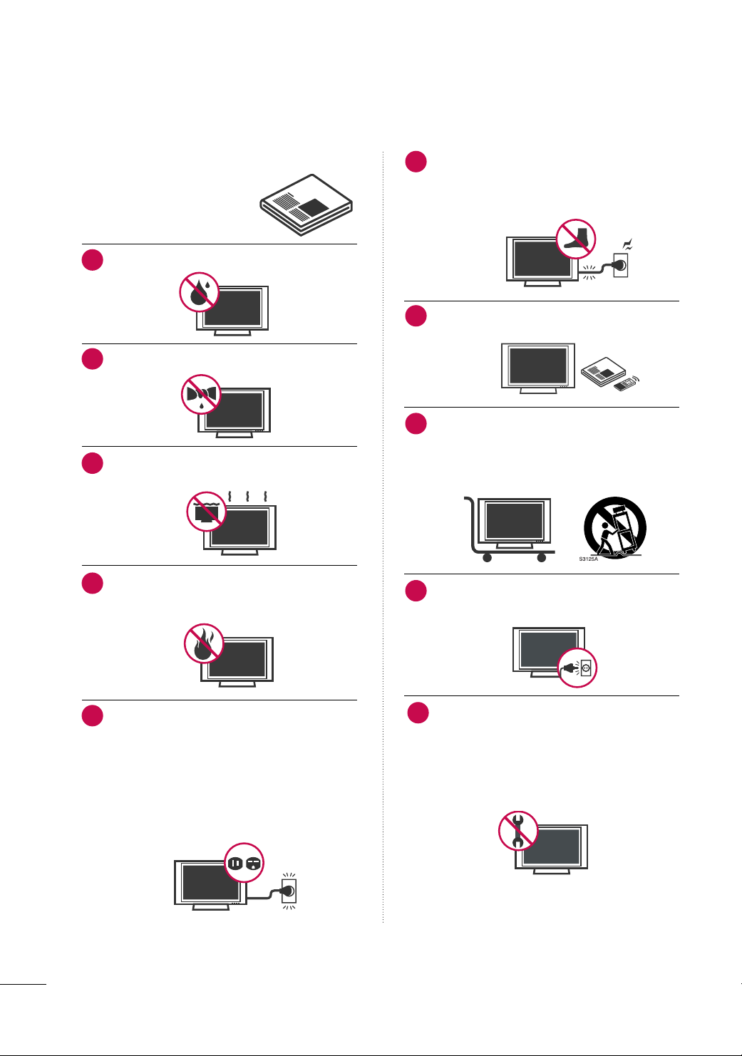
Do not use this apparatus near water.
1
Clean only with dry cloth.
2
Do not block any ventilation openings. Install in
3
accordance with the manufacturer’s instructions.
Protect the power cord from being walked on
6
or pinched particularly at plugs, convenience
receptacles, and the point where they exit from
the apparatus.
Only use attachments/accessories specified by
7
the manufacturer.
Use only with the cart, stand, tripod, bracket,
8
or table specified by the manufacturer, or sold
with the apparatus. When a cart is used, use
caution when moving the cart/apparatus
combination to avoid injury from tip-over.
Do not install near any heat sources such as
4
radiators, heat registers, stoves, or other apparatus
(including amplifiers)that produce heat.
Do not defeat the safety purpose of the polarized
5
or grounding-type plug. A polarized plug has
two blades with one wider than the other. A
grounding type plug has two blades and a third
grounding prong, The wide blade or the third
prong are provided for your safety. If the provided
plug does not fit into your outlet, consult an
electrician for replacement of the obsolete outlet.
Unplug this apparatus during lighting storms or
9
when unused for long periods of time.
Refer all servicing to qualified service personnel.
10
Servicing is required when the apparatus has been
damaged in any way, such as power-supply cord or
plug is damaged, liquid has been spilled or objects
have fallen into the apparatus, the apparatus has
been exposed to rain or moisture, does not operate
normally, or has been dropped.
2
Never touch this apparatus or antenna during a
11
thunder or lighting storm.
When mounting a TV on the wall, make sure not to
12
install the TV by the hanging power and signal
cables on the back of the TV.
Do not allow an impact shock or any objects to fall
13
into the product, and do not drop onto the screen
with something.
CAUTION concerning the Power Cord :
14
It is recommend that appliances be placed upon a
dedicated circuit; that is, a single outlet circuit which
powers only that appliance and has no additional
outlets or branch circuits. Check the specification
page of this owner's manual to be certain.
Do not connect too many appliances to the same
AC power outlet as this could result in fire or electric shock.
Do not overload wall outlets. Overloaded wall outlets, loose or damaged wall outlets, extension cords,
frayed power cords, or damaged or cracked wire
insulation are dangerous. Any of these conditions
could result in electric shock or fire. Periodically
examine the cord of your appliance, and if its
appearance indicates damage or deterioration,
unplug it, discontinue use of the appliance, and
have the cord replaced with an exact replacement
part by an authorized servicer. Protect the power
cord from physical or mechanical abuse, such as
being twisted, kinked, pinched, closed in a door, or
walked upon. Pay particular attention to plugs, wall
outlets, and the point where the cord exits the
appliance.
Do not make the TV with the power cord plugged
in. Do not use a damaged or loose power cord. Be
sure do grasp the plug when unplugging the power
cord. Do not pull on the power cord to unplug the
TV.
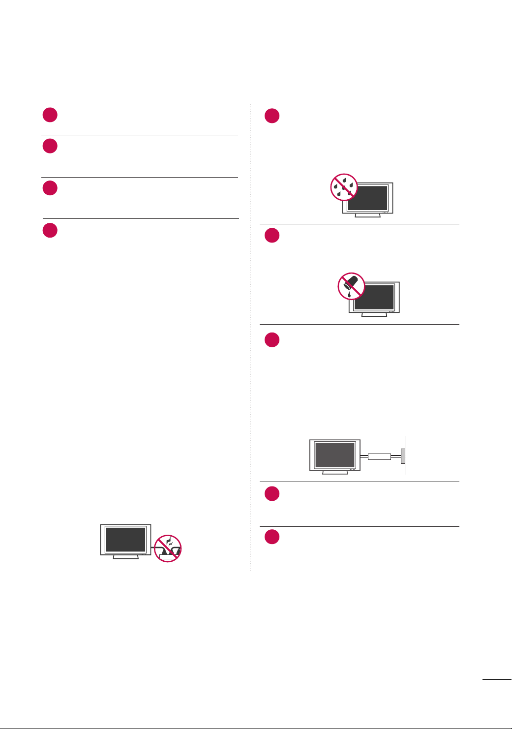
WARNING - To reduce the risk of fire or electrical
15
shock, do not expose this product to rain, moisture
or other liquids. Do not touch the TV with wet
hands. Do not install this product near flammable
objects such as gasoline or candles or expose the
TV to direct air conditioning.
Do not expose to dripping or splashing and do not
16
place objects filled with liquids, such as vases, cups,
etc. on or over the apparatus (e.g. on shelves above
the unit).
GGRROOUUNNDDIINNGG
17
Ensure that you connect the earth ground wire to
prevent possible electric shock. (i.e. a TV with a
three-prong grounded AC plug must be connected
to a three-prong grouned AC outlet) If grounding
methods are not possible, have a qualified electrician install a separate circuit breaker.
Do not try to ground the unit by connecting it to
telephone wires, lightening rods, or gas pipes.
Short-circuit
Breaker
DDIISSCCOONNNNEECCTTIINNGG DDEEVVIICCEE FFRROOMM MMAAIINNSS
18
Mains plug is the disconnecting device. The plug
must remain readily operable.
Power
Supply
Keep the product away from direct sunlight.
19
3
Cleaning
20
When cleaning, unplug the power cord and scrub
gently with a soft cloth to prevent scratching. Do not
spray water or other liquids directly on the TV as
electric shock may occur. Do not clean with chemicals such as alcohol, thinners or benzene.
Moving
21
Make sure the product is turned off, unplugged
and all cables have been removed. It may take 2 or
more people to carry larger TVs. Do not press
against or put stress on the front panel of the TV.
Ventilation
22
Install your TV where there is proper ventilation. Do
not install in a confined space such as a bookcase.
Do not cover the product with cloth or other materials (e.g.) plastic while plugged in. Do not install in
excessively dusty places.
If you smell smoke or other odors coming from the
23
TV or hear strange sounds, unplug the power cord
contact an authorized service center.
Do not press strongly upon the panel with a hand or
24
sharp object such as nail, pencil or pen, or make a
scratch on it.
4

CONTENTS
WARNING / CAUTION
SAFETY INSTRUCTIONS
. . . . . . . . . . . . . . . . . . . . . . . . . . . . 1
. . . . . . . . . . . . . . . . . . . . . . . . . . 2
PREPARATION
Accessories
Front Panel Information
Back Panel Information . . . . . . . . . . . . . . . . . . . . . . . . . . . . . . . . . . . . 10
Stand Installation
Cable Management . . . . . . . . . . . . . . . . . . . . . . . . . . . . . . . . . . . . . . . . . 14
Desktop Pedestal Installation . . . . . . . . . . . . . . . . . . . . . . . . . . . . 15
Wall Mount (Horizontal Installation)
Attaching the tv to a desk
Protection Cover
Positioning your Display
Kensington Security System
Swivel Stand . . . . . . . . . . . . . . . . . . . . . . . . . . . . . . . . . . . . . . . . . . . . . . . . . . . .18
Antenna or Cable Connection
. . . . . . . . . . . . . . . . . . . . . . . . . . . . . . . . . . . . . . . . . . . . . . . . . . . . . . 7
. . . . . . . . . . . . . . . . . . . . . . . . . . . . . . . . . . . . . 8
. . . . . . . . . . . . . . . . . . . . . . . . . . . . . . . . . . . . . . . . . . . . 12
. . . . . . . . . . . . . . . . . 15
. . . . . . . . . . . . . . . . . . . . . . . . . . . . . . . . 15
. . . . . . . . . . . . . . . . . . . . . . . . . . . . . . . . . . . . . . . . . . . . . 16
. . . . . . . . . . . . . . . . . . . . . . . . . . . . . . . . . . .18
. . . . . . . . . . . . . . . . . . . . . . . . . . . . . 18
. . . . . . . . . . . . . . . . . . . . . . . . . . 19
EXTERNAL EQUIPMENT SETUP
HD Receiver Setup
Headphone Setup
DVD Setup
VCR Setup
PC Setup
. . . . . . . . . . . . . . . . . . . . . . . . . . . . . . . . . . . . . . . . . . . . . . . . . . . . . . . .27
External Stereo Setup
AV Out Setup
Screen Setup For PC Mode
. . . . . . . . . . . . . . . . . . . . . . . . . . . . . . . . . . . . . . . . .20
. . . . . . . . . . . . . . . . . . . . . . . . . . . . . . . . . . . . . . . . . . . 22
. . . . . . . . . . . . . . . . . . . . . . . . . . . . . . . . . . . . . . . . . . . . . . . . . . . . . 23
. . . . . . . . . . . . . . . . . . . . . . . . . . . . . . . . . . . . . . . . . . . . . . . . . . . . . 25
. . . . . . . . . . . . . . . . . . . . . . . . . . . . . . . . . . . . . .29
. . . . . . . . . . . . . . . . . . . . . . . . . . . . . . . . . . . . . . . . . . . . . . . . . .30
. . . . . . . . . . . . . . . . . . . . . . . . . . . . . . .31
WATCHING TV / CHANNEL CONTROL
Remote Control Functions . . . . . . . . . . . . . . . . . . . . . . . . . . . . . . .34
Turning On TV
Channel Selection . . . . . . . . . . . . . . . . . . . . . . . . . . . . . . . . . . . . . . . . . . .36
Volume Adjustment
On-Screen Menus Selection . . . . . . . . . . . . . . . . . . . . . . . . . . . . .37
Channel Search
- Auto Tuning (Program Search)
- Manual Tuning (Additing/Deleting Channels) . .
. . . . . . . . . . . . . . . . . . . . . . . . . . . . . . . . . . . . . . . . . . . . . . . . . . . . . . . . . . . . . . . . . . . . . .
Fine Tuning Adjustment
Booster . . . . . . . . . . . . . . . . . . . . . . . . . . . . . . . . . . . . . . . . . . . . . . . . . . . . . . . . . . 41
Favorite Channels Setup
Key Lock
. . . . . . . . . . . . . . . . . . . . . . . . . . . . . . . . . . . . . . . . . . . . . . . .36
. . . . . . . . . . . . . . . . . . . . . . . . . . . . . . . . . . . . . . . . .36
. . . . . . . . . . . . . . . . . . . 38
39
. . . . . . . . . . . . . . . . . . . . . . . . . . . . . . . . . . .40
. . . . . . . . . . . . . . . . . . . . . . . . . . . . . . . . . .42
. . . . . . . . . . . . . . . . . . . . . . . . . . . . . . . . . . . . . . . . . . . . . . . . . . . . . . . . . 43
PICTURE CONTROL
Picture Size (Aspect Ratio) Control . . . . . . . . . . . . . . . . . . 44
Preset Picture Settings
- Picture Mode - Preset
- Auto Color Tone Control
. . . . . . . . . . . . . . . . . . . . . . . . . . . . . . . 45
. . . . . . . . . . . . . . . . . . . . . . . . . 46
Manual Picture Adjustment
- Picture Mode - User Mode
- Color Tone - User Mode
. . . . . . . . . . . . . . . . . . . . . . . .
. . . . . . . . . . . . . . . . . . . . . . . . . . .48
XD - Picture Improvement Technology
Advanced - Gamma
Advanced - Film Mode
Advanced - Black (Darkness) Level
Advanced - Eye care
Picture Reset
Power Indicator
Factory Reset
. . . . . . . . . . . . . . . . . . . . . . . . . . . . . . . . . . . . . . . . .50
. . . . . . . . . . . . . . . . . . . . . . . . . . . . . . . . . . . . . 51
. . . . . . . . . . . . . . . . . . . 52
. . . . . . . . . . . . . . . . . . . . . . . . . . . . . . . . . . . . . . . . 53
. . . . . . . . . . . . . . . . . . . . . . . . . . . . . . . . . . . . . . . . . . . . . . . . .54
. . . . . . . . . . . . . . . . . . . . . . . . . . . . . . . . . . . . . . . . . . . . . . . 55
. . . . . . . . . . . . . . . . . . . . . . . . . . . . . . . . . . . . . . . . . . . . . . . . .56
. . . . . . . . . . . . .49
47
SOUND & LANGUAGE CONTROL
Auto Volume Leveler (Auto Volume) . . . . . . . . . . . . . . . . . 57
Preset Sound Settings (Sound Mode)
Sound Setting Adjustment - User Mode
Balance
TV Speakers On/Off Setup
Selecting Audio Out
. . . . . . . . . . . . . . . . . . . . . . . . . . . . . . . . . . . . . . . . . . . . . . . . . . . . . . . . . .
. . . . . . . . . . . . . . . . . . . . . . . . . . . . . .
. . . . . . . . . . . . . . . . . . . . . . . . . . . . . . . . . . . . . . . . 62
On-Screen Menus Language Selection
Closed Captions
Stereo/SAP Broadcasts Setup
. . . . . . . . . . . . . . . . . . . . . . . . . . . . . . . . . . . . . . . . . . . . . 64
. . . . . . . . . . . . . . . . . . . . . . . . . . 65
. . . . . . . . . . . . . . 58
. . . . . . . . . . . 59
60
61
. . . . . . . . . . . . .63
TIME SETTING
Clock Setup . . . . . . . . . . . . . . . . . . . . . . . . . . . . . . . . . . . . . . . . . . . . . . . . . . . . 66
Auto On/Off Time Setting
Sleep Timer Setting
Auto Shut-Off Setting
. . . . . . . . . . . . . . . . . . . . . . . . . . . . . . . 67
. . . . . . . . . . . . . . . . . . . . . . . . . . . . . . . . . . . . . . . . .68
. . . . . . . . . . . . . . . . . . . . . . . . . . . . . . . . . . . . . . 69
APPENDIX
Troubleshooting . . . . . . . . . . . . . . . . . . . . . . . . . . . . . . . . . . . . . . . . . . . . . .70
Maintenance
Product Specifications . . . . . . . . . . . . . . . . . . . . . . . . . . . . . . . . . . . . . 73
External Control Through RS-232C
. . . . . . . . . . . . . . . . . . . . . . . . . . . . . . . . . . . . . . . . . . . . . . . . . . . 72
. . . . . . . . . . . . . . . . . .74
5

■
If the TV feels cold to the touch, there may be a small “flicker” when it is turned on. This is normal, there is
nothing wrong with TV.
■
Some minute dot defects may be visible on the screen, appearing as tiny red, green, or blue spots. However, they
have no adverse effect on the monitor's performance.
■
Avoid touching the LCD screen or holding your finger(s) against it for long periods of time. Doing so may produce
some temporary distortion effects on the screen.
On Disposal
a. The fluorescent lamp used in this product contains a small amount of mercury.
b. Do not dispose of this product with general household waste.
c. Disposal of this product must be carried out in accordance to the regulations of your local authority.
6
PREPARATION
1.5V 1.5V
123
456
78
0
9
VOL VOL
CH
CH
E
N
T
E
R
Q
.
V
IE
W
S
L
E
E
P
R
A
T
I
O
F
A
V
M
U
T
E
O
G
MEMORY/ERASE
C
A
P
T
I
O
N
I
N
P
U
T
123
456
78
0
9
VOL VOL
CH
CH
E
N
T
E
R
P
O
W
E
R
M
E
N
U
Q
.
V
I
E
W
S
L
E
E
P
R
A
T
I
O
M
T
S
F
A
V
M
U
T
E
A
.
P
R
O
G
CAPTION
T
V
IN
P
U
T
MEMORY/ER
ASE
S
O
U
N
D
P
I
C
T
U
R
E
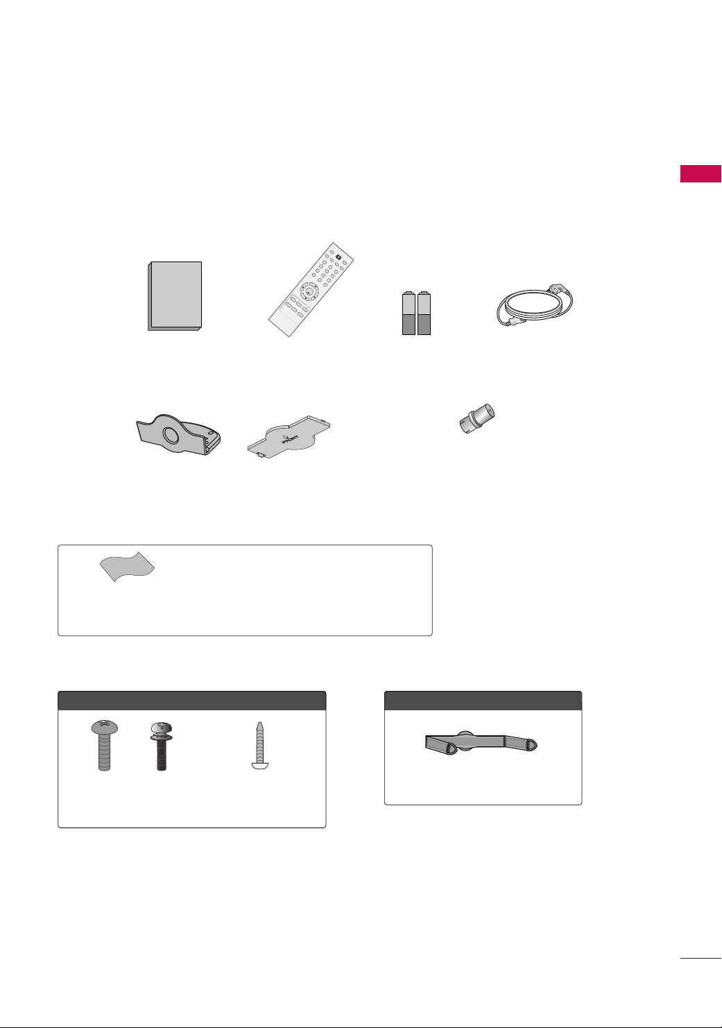
ACCESSORIES
Ensure that the following accessories are included with your TV. If an accessory is missing, please contact the
dealer where you purchased the TV.
The accessories included may differ from the images below.
PREPARATION
Owner’s Manual Power Cord
Polishing Cloth
(This feature is not available
for all models.)
For 26/32LF15R
x 4
Remote Control
or
Protection Cover
* Wipe spots on the exterior only with the polishing cloth.
* Do not wipe roughly when removing stain. Please be
cautions of that excessive pressure may cause scratch or
discoloration.
x 4
Batteries
RF Adapter (Some Models)
You must connect it to the antenna
wire after fixing in Antenna Input.
This adapter is only supplied in
Argentina.
For 22LG30R/C, 22LF15R
Screws for
stand assembly
(Refer to P.13)
Screw for stand fixing
(Refer to P.15)
Cable Management Clip
7
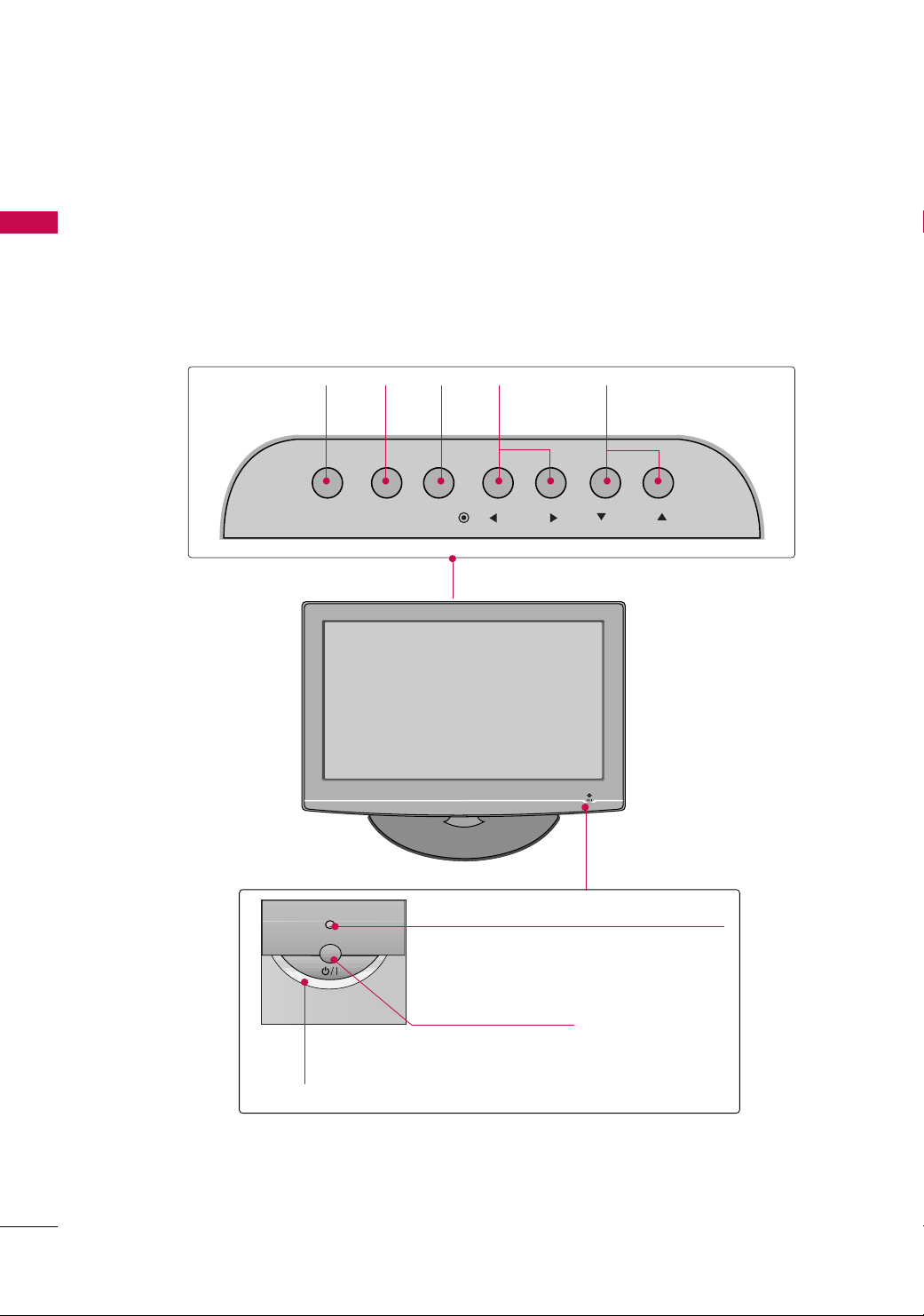
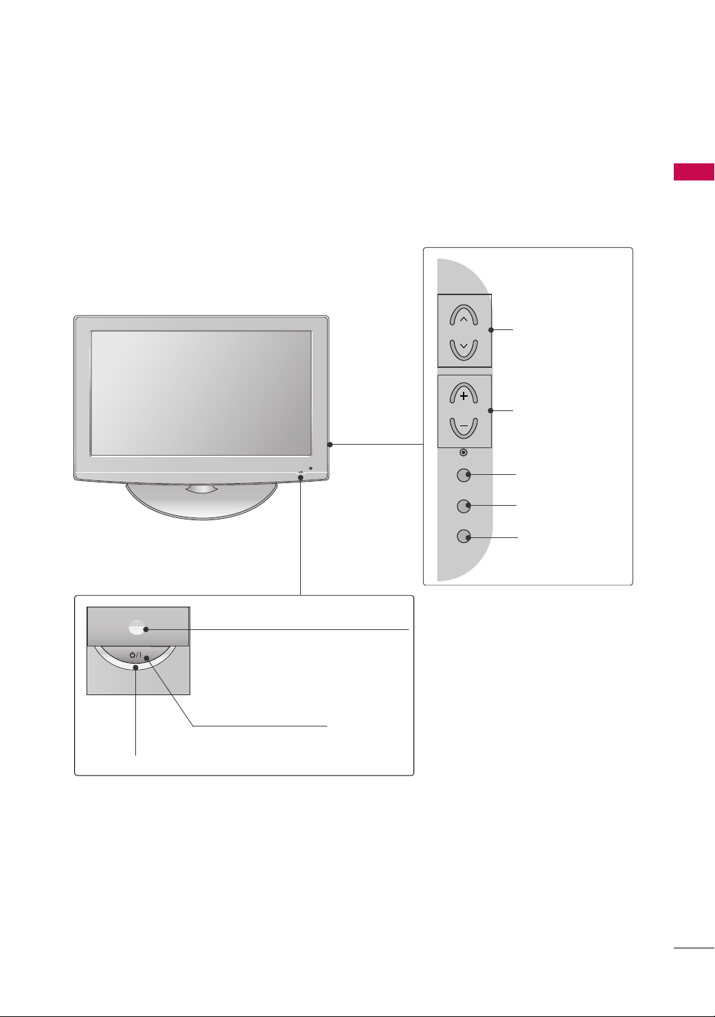
PREPARATION
FRONT PANEL INFORMATION
■
Image shown may differ from your TV.
PREPARATION
For 22LG30R/C, 22LF15R
INPUT
Button
INPUT
MENU
Button
MENU
ENTER
Button
ENTER
VOLUME
FF,GG
(
) Buttons
VOL CH
CHANNEL
EE,DD
(
) Buttons
Power/Standby Indicator
Illuminates red in standby mode.
Illuminates blue when the TV is switched on.
Remote Control Sensor
POWER Button
8
For 26/32LF15R
PREPARATION
Power/Standby Indicator
Illuminates red in standby mode.
Illuminates blue when the set is switched on.
(Can be adjusted
Option menu.)
POWER Button
PPoowweerr IInnddiiccaattoorr
Remote Control Sensor
in the
CH
VOL
ENTER
MENU
INPUT
CHANNEL
Buttons
VOLUME
Buttons
ENTER Button
MENU Button
INPUT Button
9
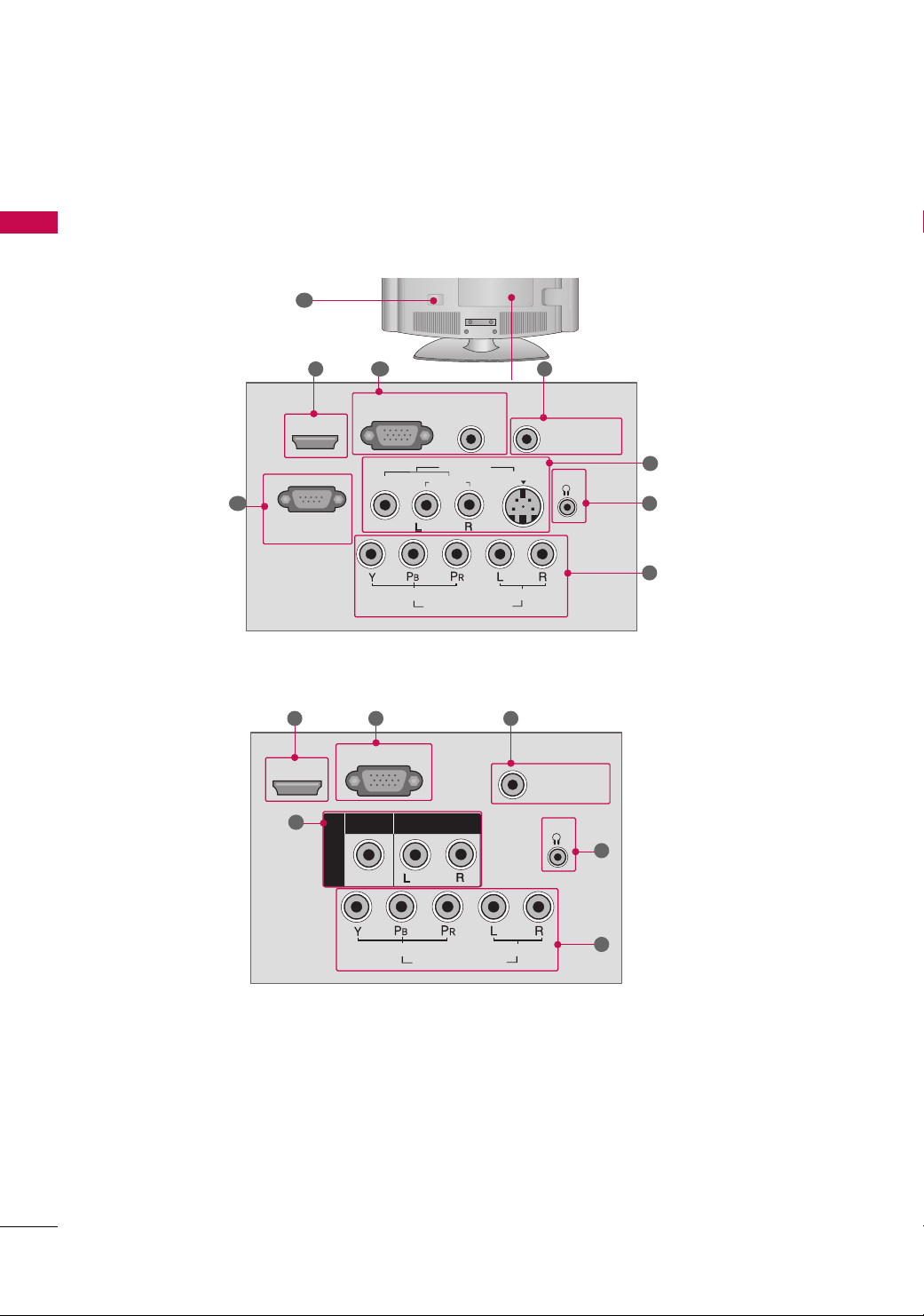
PREPARATION
ANTENNA IN
SERVICE ONLY
AUDIO
COMPONENT IN
VIDEO
MONO
( )
H/P
HDMI IN
( )
AV IN
VIDEO
AUDIO
ANTENNA IN
RGB(PC) IN
RS-232C IN
(CONTROL & SERVICE)
AUDIO
(RGB/DVI) IN
S-VIDEO
AUDIO
COMPONENT IN
VIDEO
VIDEO
AUDIO
MONO
( )
AV IN
H/P
HDMI/DVI IN
BACK PANEL INFORMATION
■
Image shown may differ from your TV.
PREPARATION
For 22LG30R/C
10
For 22LF15R
1 2
4
1
5
9
3
5
7
8
3
7
10
8
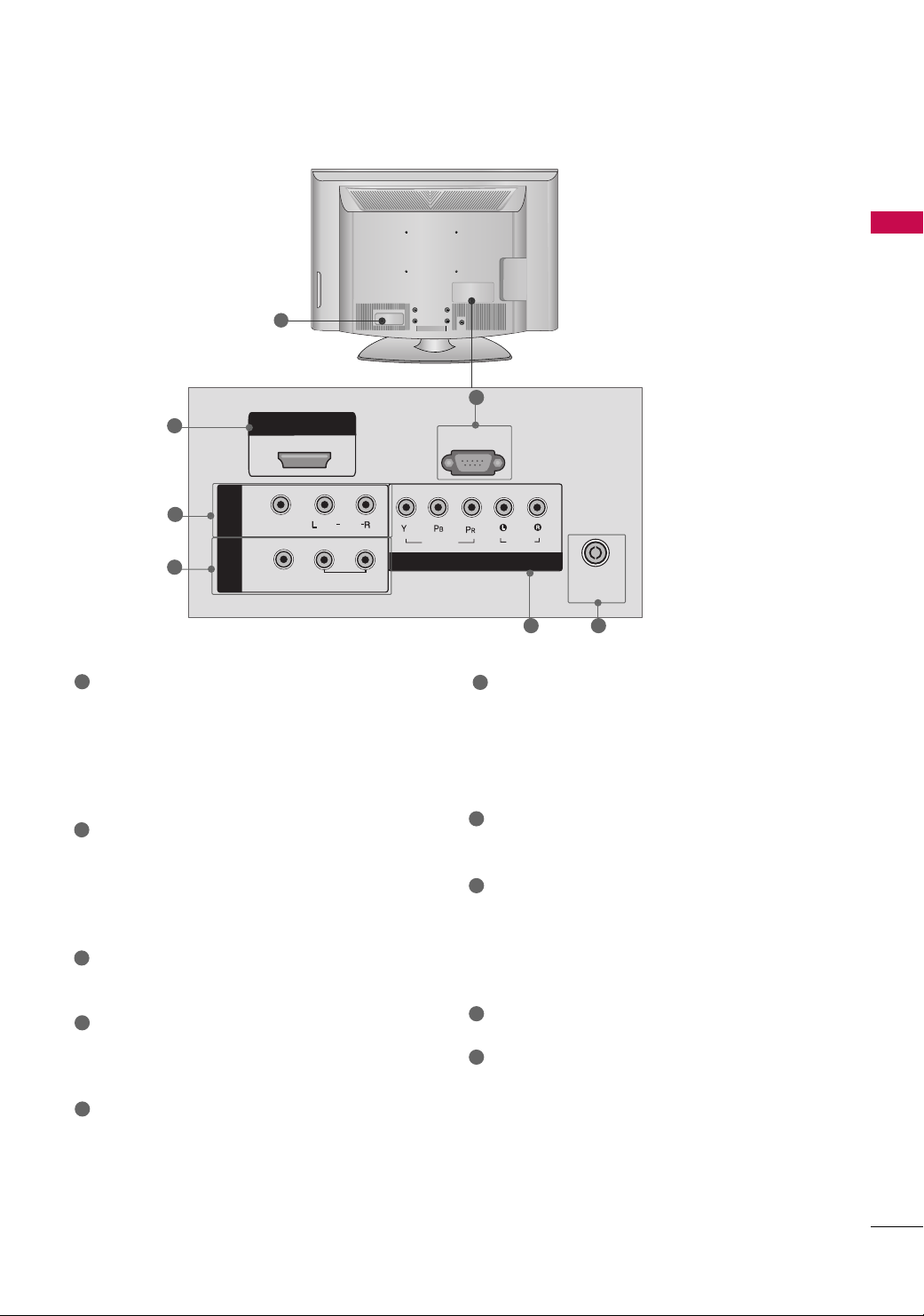
For 26/32LF15R
1
PREPARATION
10
9
HDMI IN
SERVICE ONLY
5
6
1
HDMI/DVI IN, HDMI IN
IN
AV
OUT
VIDEO
(
)
AUDIO
MONO
VARIABLE
AUDIO OUT
Digital Connection.
Supports HD video and Digital audio. Doesn’t
support 480i(For 22LG30R/C)/576i.
Accepts DVI video using an adapter or HDMI to
DVI cable (not included) (For 22LG30R/C).
2
RGB (PC) IN (For 22LG30R/C)
Analog PC Connection. Uses a D-sub 15 pin cable
(VGA cable).
AUDIO (RGB/DVI) IN
1/8" (0.32 cm) headphone jack for analog PC audio input.
ANTENNA IN
3
Connect over-the air signals to this jack.
4
RS-232C IN (CONTROL & SERVICE) PORT
(For 22LG30R/C)
Used by third party devices.
5
AV (Audio/Video) IN
Analog composite connection. Supports standard
definition video only (480i).
S-VIDEO (For 22LG30R/C)
Better quality than standard composition.
Supports standard definition video only (480i).
VIDEO
COMPONENT IN
6
7
8
9
10
AUDIO
ANTENNA
IN
8
3
AV OUT (For 26/32LF15R)
Connect second TV or monitor to the AV OUT
socket on the TV.
VARIABLE AUDIO OUT
Connect an external amplifier or add a subwoofer
to your surround sound system.
Headphone INPUT (Except 26/32LF15R)
Plug the headphone into the headphone socket.
COMPONENT IN
Analog Connection.
Supports HD.
Uses a red, green, and blue cable for video & red
and white for audio.
SERVICE ONLY (Except 22LG30R/C)
Power Cord Socket
For operation with AC power.
Caution: Never attempt to operate the TV on DC
power.
11
PREPARATION
STAND INSTALLATION
■
Image shown may differ from your TV
PREPARATION
For 22LG30R/C, 22LF15R
Carefully place the TV screen side down on a
1
cushioned surface to protect the screen from
damage.
Assemble the parts of the
2
CCOOVVEERR BBAASSEE
BBOO DD YY
into a
of the TV. Insert the
CCOOVVEERR BBAASSEE
SSTTAANNDD BBOODDYY
until clicking sound.
with
SSTTAANNDD
SSTTAANNDD BBOODDYY
CCOOVV EERR BBAASSEE
12
Assemble the TV as shown.
3
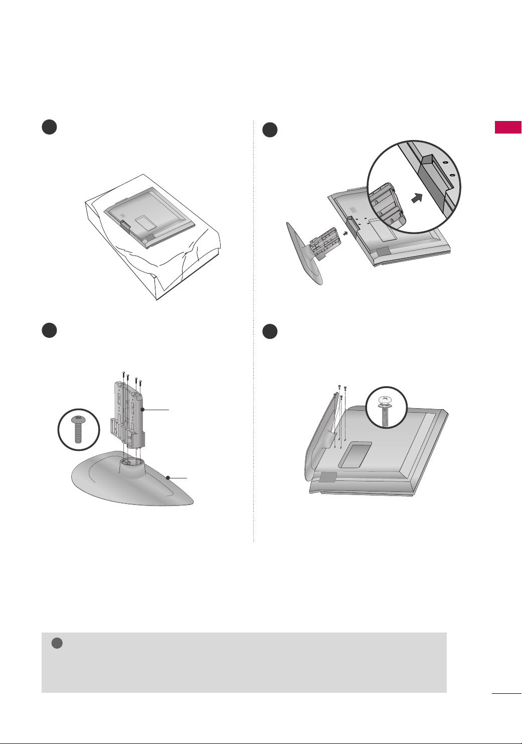
!
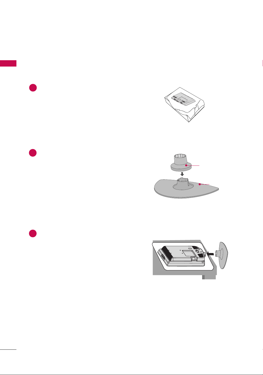
For 26/32LF15R
Carefully place the TV screen side down on a
1
cushioned surface to protect the screen from
damage.
Assemble the TV as shown.
3
PREPARATION
Assemble the parts of the
2
CCoovveerr BBaassee
the
of the TV.
SStt aanndd BBooddyy
SSTTAANNDD BBOODDYY
CCOOVV EERR BBAASSEE
with
Fix the 4 screws securely using the holes in the
4
back of the TV.
NOTE
When assembling the desk type stand, check whether the screw is fully tightened. (If not tightened
GG
fully, the product can tilt forward after the product installation). If you tighten the screw with excessive force, the screw can deviate from abrasion of the tightening part of the screw.
13
PREPARATION
!
PREPARATION
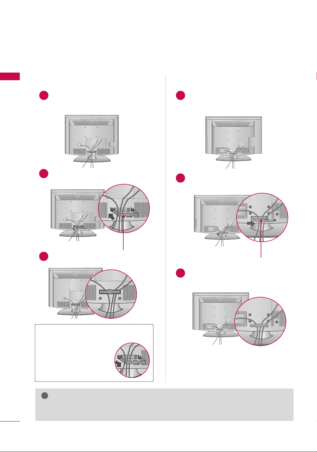
CABLE MANAGEMENT
■
Image shown may differ from your TV
For 22LG30R/C, 22LF15R
Connect the cables as necessary.
1
To connect additional equipment, see the
EXTERNAL EQUIPMENT SETUP section.
Install the CABLE MANAGEMENT CLIP as
2
shown.
For 22LG30R/C, 22/26/32LF15R
For 26/32LF15R
Connect the cables as necessary.
1
To connect additional equipment, see the
EXTERNAL EQUIPMENT SETUP section.
Install the CABLE MANAGEMENT CLIP as
2
shown.
CABLE MANAGEMENT CLIP
3
Fit the CABLE MANAGEMENT CLIP as shown.
Put the cables inside the CABLE MANAGEMENT
3
CLIP and snap it closed.
How to remove the
CABLE MANAGEMENT CLIP
Hold the CABLE MANAGE-
GG
MENT CLIP with both hands
and pull it backward.
NOTE
Do not hold the CABLE MANAGEMENT CLIP when moving the TV.
GG
- If the TV is dropped, you may be injured or the product may be broken.
CCAABBLLEE MMAANNAAGGEEMMEENNTT CCLL IIPP
14
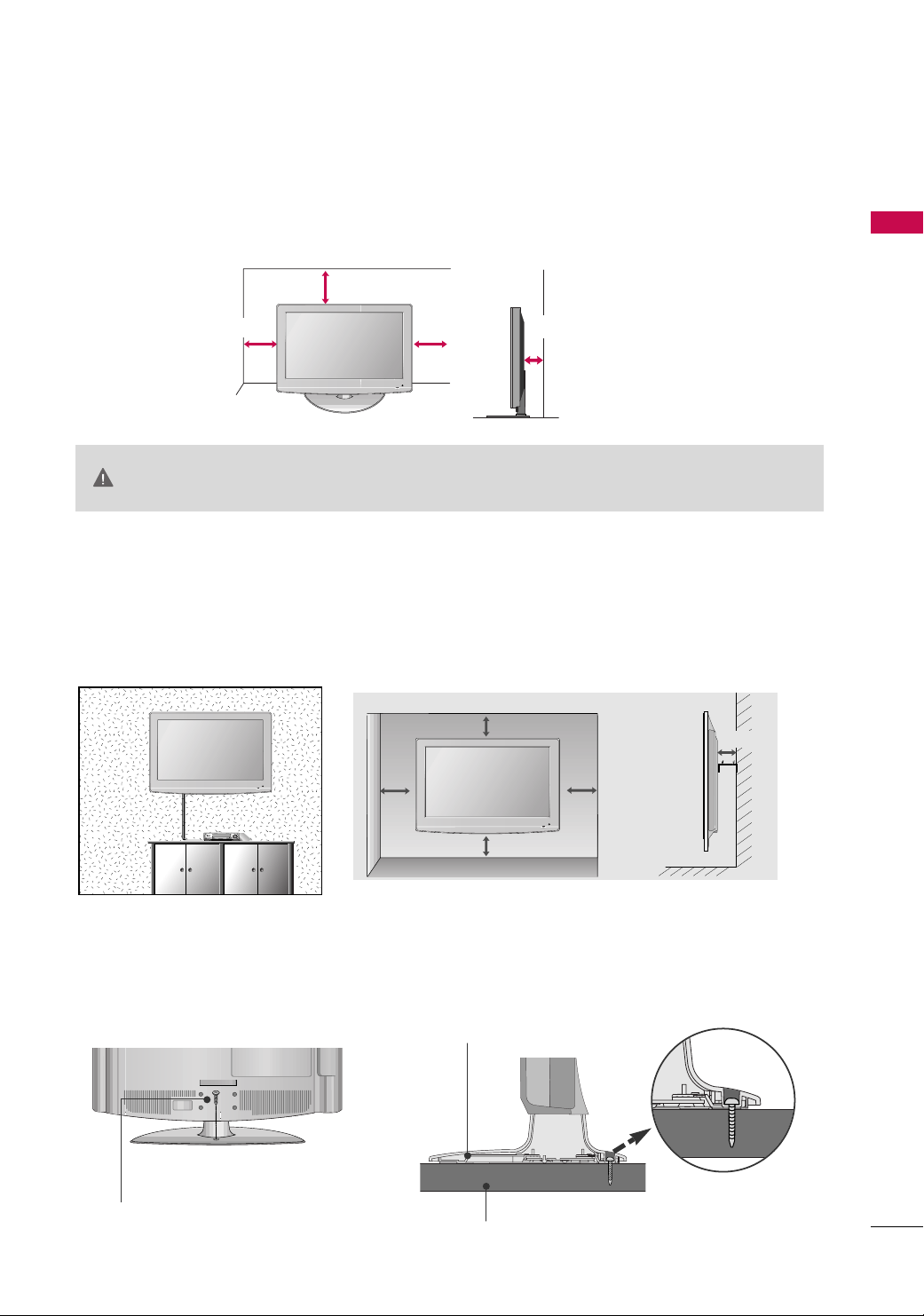
DESKTOP PEDESTAL INSTALLATION
■
Image shown may differ from your TV.
For proper ventilation, allow a clearance of 4 inches on all four sides from the wall.
4 inches
CAUTION
4 inches
Ensure adequate ventilation by following the clearance recommendations.
GG
Do not mount near or above any type of heat source.
GG
4 inches
4 inches
WALL MOUNT: HORIZONTAL INSTALLATION
For adequate ventilation allow a clearance of 4” (10cm) all around the TV. We recommend that you
use an LG brand wall mount when mounting the TV to a wall.
4 inches
4 inches
PREPARATION
4 inches
4 inches
ATTACHING THE TV TO A DESK
If you wish to attach the TV to a desk, it must be securely fastened to the desk using a metal screw (as shown
below). Failure to securely attach the TV may result in the TV falling: which may cause damage to the TV and
serious personal injury.
1-Screw
(provided as parts of the product)
For 26/32LF15R
Stand
Desk
4 inches
15
PREPARATION
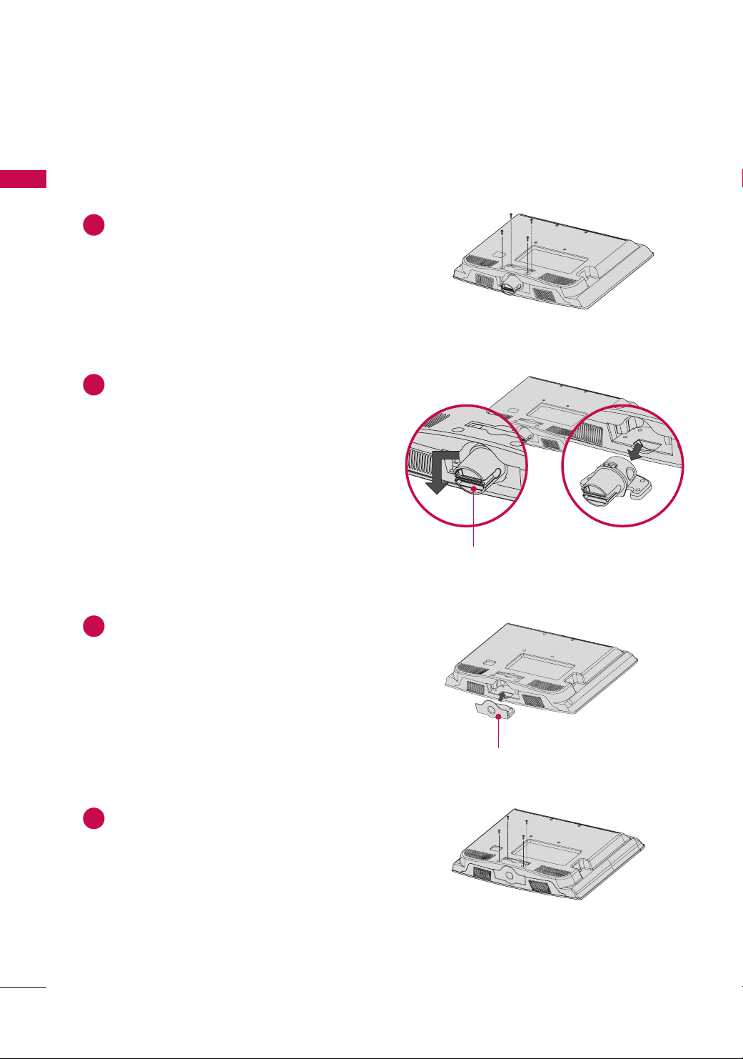
PROTECTION COVER
■
Image shown may differ from your TV.
PREPARATION
For 22LG30R/C, 22LF15R
Loose the screws from the TV.
1
2
Bend the
HHIINNGGEE BBOODDYY
and pull it backward.
HHIINNGGEE BBOODDYY
16
Insert the
3
Fix the 4 screws securely using the holes in the
4
back of the TV.
PPRROOTT EECCTTIIOONN CCOOVVEE RR
into the TV.
PPRROOTT EECCTTIIOONN CCOOVV EERR

For 26/32LF15R
PREPARATION
After removing the stand, install the included
Press the
PPRROOTTEECCTTIIOONN CCOOVVEERR
into the TV until you hear it click.
pp rroott eeccttiioonn ccoovvee rr
over the hole for the stand.
17
PREPARATION
12
0
3
0
PREPARATION
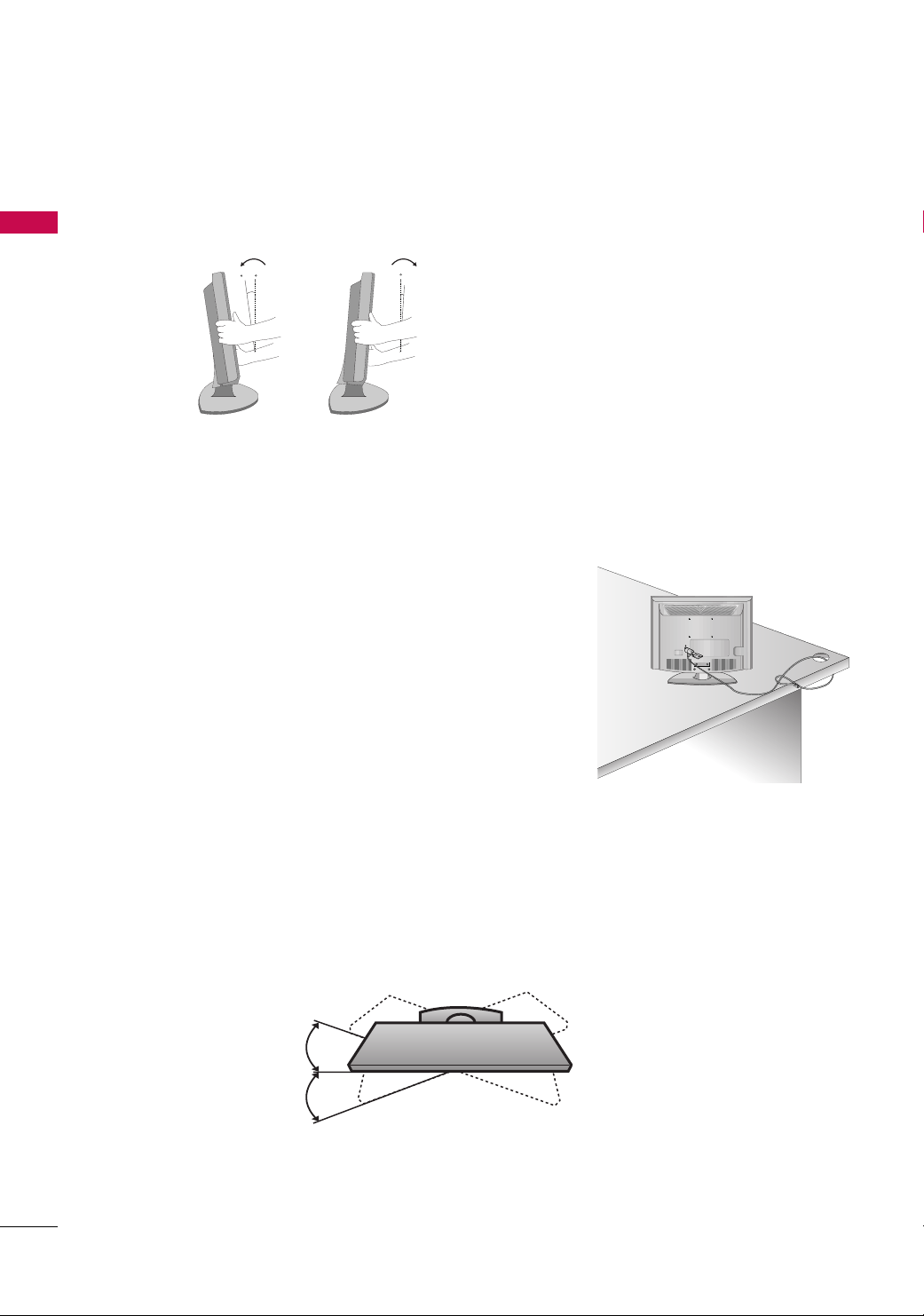
POSITIONING YOUR DISPLAY
■
Here shown may be somewhat different from your TV.
■
Adjust the position of the panel in various ways for maximum comfort.
• Tilt range
KENSINGTON SECURITY SYSTEM
- The TV is equipped with a Kensington Security System connector on
the back panel. Connect the Kensington Security System cable as
shown below.
- For the detailed installation and use of the Kensington Security
System, refer to the user’s guide provided with the Kensington
Security System.
For further information, contact
the internet homepage of the Kensington company. Kensington sells
security systems for expensive electronic equipment such as notebook PCs and LCD projectors.
hhtt ttpp :://// wwwwww ..kkee nn ssii nn ggttoonn..ccoomm
For 22LG30R/C, 22LF15R
For 22LG30R/C, 22LF15R
,
18
NOTE: The Kensington Security System is an optional accessory.
SWIVEL STAND
TThhiiss ff eeaattuurree iiss nnoott aavvaaiillaabbllee ffoorr aa ll ll mmooddeellss ..
After installing the TV, you can adjust the TV set manually to the left or right direction by 20 degrees to suit
your viewing position.
For 26/32LF15R
■
ANTENNA IN
ANTENNA IN
ANTENNA IN
To prevent damage do not connect to the power outlet until all connections are made between the devices.
■
Image shown may differ from your TV.
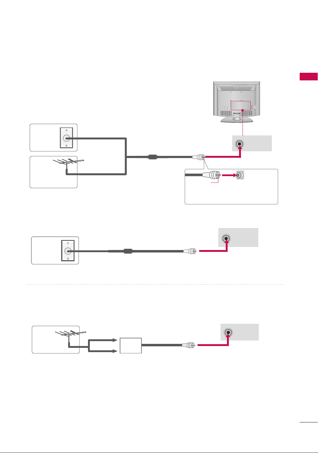
ANTENNA OR CABLE CONNECTION
1. Antenna (Analog)
Wall Antenna Socket or Outdoor Antenna without a Cable Box
Connections.
For optimum picture quality, adjust antenna direction if needed.
Wall
Multi-family Dwellings/Apartments
(Connect to wall antenna socket)
Antenna
Socket
Outdoor
RF Coaxial Wire (75 ohm)
Antenna
(VHF, UHF)
Single-family Dwellings /Houses
(Connect to wall jack for outdoor antenna)
2. Cable
Cable TV
Wall Jack
RF Coaxial Wire (75 ohm)
PREPARATION
Copper Wire
Be careful not to bend the bronze wire
when connecting the antenna.
■
To improve the picture quality in a poor signal area, please purchase a signal amplifier and install properly.
■
If the antenna needs to be split for two TV’s, install a 2-Way Signal Splitter.
■
If the antenna is not installed properly, contact your dealer for assistance.
UHF
Antenna
VHF
Signal
Amplifier
19
EXTERNAL EQUIPMENT SETUP
Y
P
B
P
R
L
R
ANTEN
RGB(PC) IN
IN
ERVICE)
AUDIO
(RGB/DVI) IN
AUDIO
COMPONENT IN
VIDEO
VIDEO
AUDIO
MONO
( )
AV IN
H/P
S-VIDEO
■
To prevent the equipment damage, never plug in any power cords until you have finished connecting all equipment.
■
This part of EXTERNAL EQUIPMENT SETUP mainly use picture for
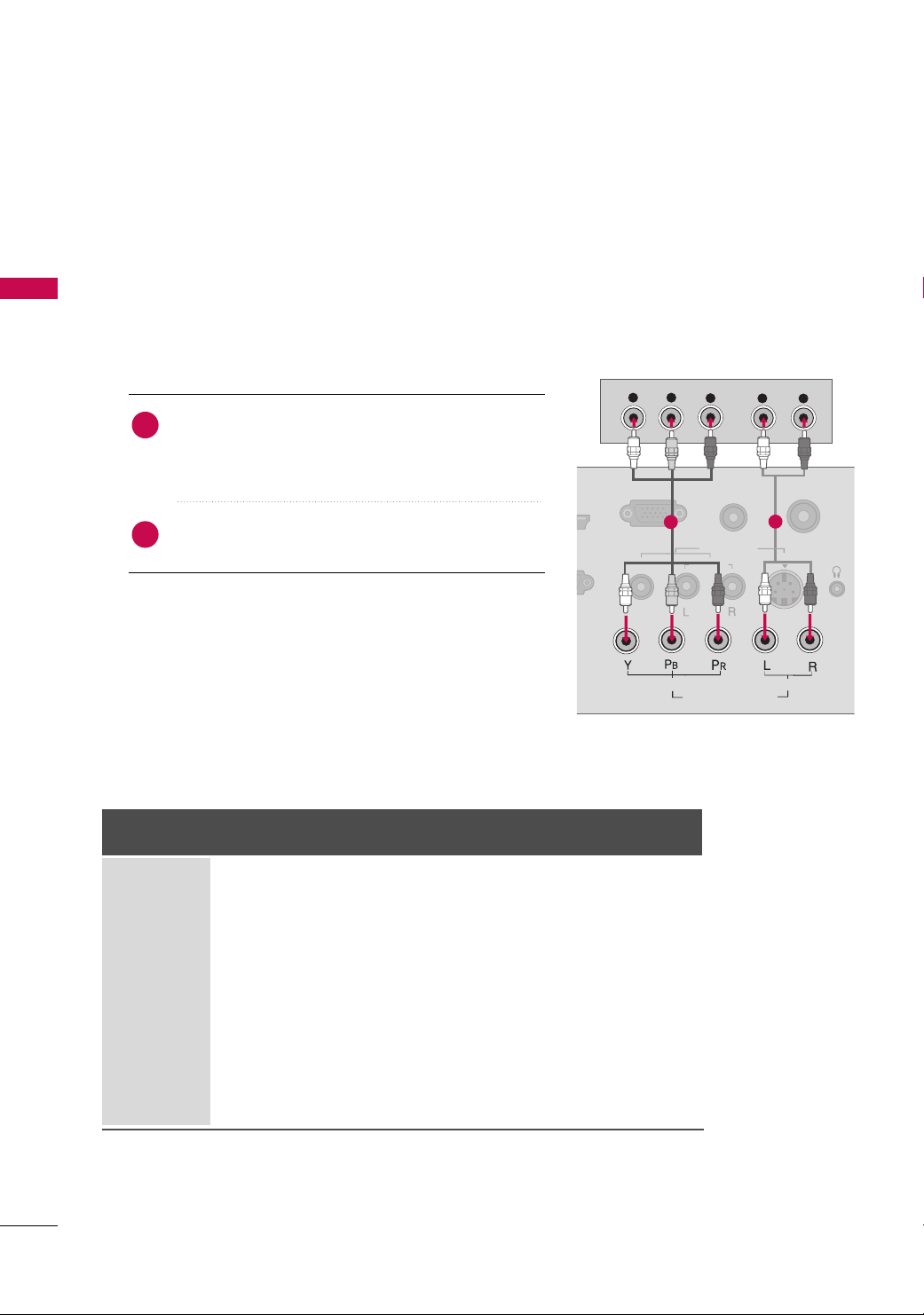
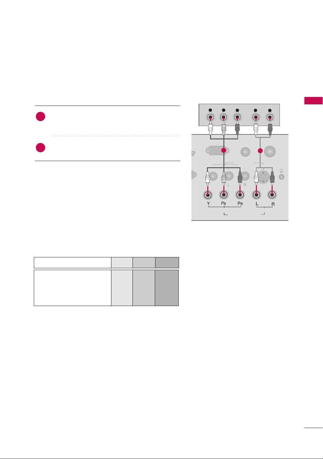
HD RECEIVER SETUP
This TV can receive Digital Over-the-air/Cable signals with an external digital set-top box. If you do receive digital signals from a digital set-top box or other digital external device, refer to the figure as shown below.
EXTERNAL EQUIPMENT SETUP
Component Connection
1. How to connect
)
Connect the video outputs (Y, P B, PR
1
top box to the
CCOOMMPPOONNEENNTT II NN VVIIDDEEOO
the TV. Match the jack colors (Y = green, P
R = red).
P
of the digital set-
jacks on
B = blue, and
the 22LG30R/C models.
Connect the audio output of the digital set-top box to
2
the
2. How to use
■
Turn on the digital set-top box.
(
Refer to the owner’s manual for the digital set-top box. operation
■
Select the
II NN PP UUTT
Signal
480i
576i
480p
576p
720 p
1080i
10 8 0 p
CCOOMMPPOONNEENNTT IINN AAUUDDIIOO
CCoommppoonneenntt
input source on the TV using the
button on the remote control.
Component
(For 22LG30R/C)
Yes
Yes
Yes
Yes
Yes
Yes
Yes
(Only 50Hz, 60Hz)
(Only 50Hz, 60Hz)
jacks on the TV.
HDMI/DVI
No
No
Yes
Yes
Yes
Yes
Yes
1
)
HDMI
(For 22/26/32LF15R)
No
No
Yes
Yes
Yes
Yes
Yes
(22LF15R - Only 50Hz, 60Hz)
(26/32LF15R - Only 24Hz,
30Hz, 50Hz, 60Hz)
2
20
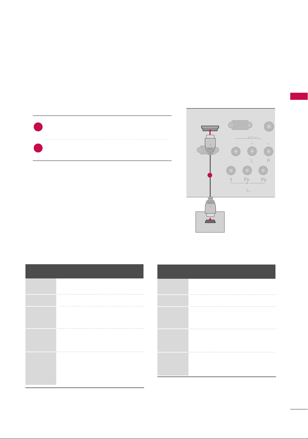
HDMI Connection
RGB(PC) IN
RS-232C IN
(CONTROL & SERVICE)
AUDIO
(RGB/DVI)
COMPONEN
VIDEO
VIDEO
AUDIO
MONO
( )
AV IN
HDMI/DVI IN
HDMI OUTPUT
1. How to connect
EXTERNAL EQUIPMENT SETUP
Connect the digital set-top box to
1
HHDDMMII IINN((FFoorr 2222//
No separate audio connection is necessary.
2
HDMI supports both audio and video.
2266//3322LLFF1155RR))
HHDDMMII//DDVVII IINN
jack on the TV.
2. How to use
■
Turn on the digital set-top box.
(
Refer to the owner’s manual for the digital set-top box.
■
Select the
input source on the TV using the
remote control.
2266//3322LLFF1155RR
FFoorr
Resolution
720x480
HHDDMMII//DDVVII
HHDDMMII((FFoorr 2222//
or
IINNPPUUTT
Horizontal Vertical
Frequency(kHz) Frequency(Hz)
31.47 59.94
31.50 60.00
2266//3322LLFF1155RR))
button on the
or
)
FFoorr
22LG30R/C, 22LF15R
Resolution
720x480p
1
Horizontal Vertical
Frequency(kHz) Frequency(Hz)
31.47 59.94
31.50 60.00
720x576
1280x720
1920x1080i
1920x1080p
31.25 50.00
44.96 59.94
45.00 60.00
37.50 50.00
33.72 59.94
33.75 60.00
28.125 50.00
67.432 59 .94
67.50 60.00
56.25 50.00
27.00 24.00
33.75 30.00
720x576p
1280x720p
1920x1080i
1920x1080p
31.25 50.00
44.96 59.94
45.00 60.00
37.50 50.00
33.72 59.94
33.75 60.00
28.125 50.00
67.432 59. 94
67.50 60.00
56.25 50.00
21
EXTERNAL EQUIPMENT SETUP
!
RGB(PC) IN
RS-232C IN
S-VIDE
AUD
COMPONENT IN
VIDEO
VIDEO
AUDIO
MONO
( )
AV IN
HDMI/DVI IN
L
R
DVI OUTPUT
AUDIO
(RGB/DVI) IN
ANTENNA IN
AUDIO
H/P
EXTERNAL EQUIPMENT SETUP
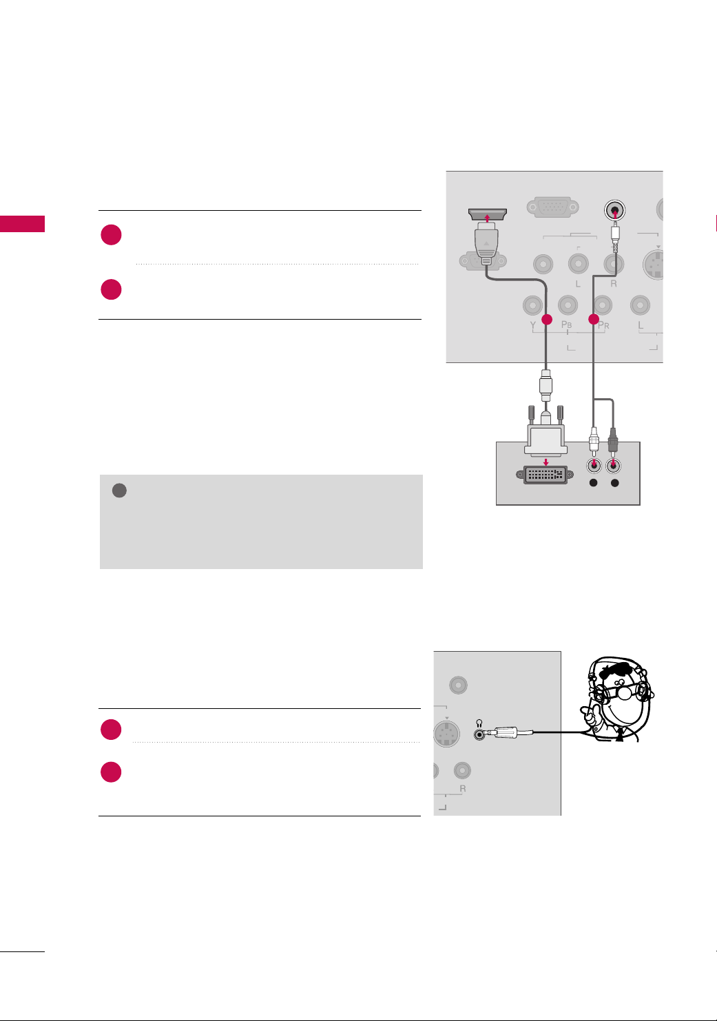
DVI to HDMI Connection
(Except 22/26/32LF15R)
1. How to connect
Connect the DVI output of the digital set-top box to the
1
HHDDMMII//DDVVII IINN
jack on the TV.
Connect the audio output of the digital set-top box to
2
AAUUDDIIOO ((RRGGBB//DDVVII )) IINN
the
jack on the TV.
2. How to use
■
Turn on the digital set-top box.
(
Refer to the owner’s manual for the digital set-top box. operation
■
Select the
II NN PP UUTT
GG
HHDDMMII //DDVV II
input source on the TV using the
button on the remote control.
NOTE
A DVI to HDMI cable or adapter is required for this
connection. DVI doesn't support audio, so a separate
audio connection is necessary.
1
2
)
22
HEADPHONE SETUP
Except 26/32LF15R
You can listen to the sound through the headphone.
1. How to connect
1
2
Plug the headphone into the headphone socket.
To adjust the headphone volume, press the
button. If you press the
GG
from the headphone is switched off.
MMUUTTEE
button, the sound
VVOOLL
FF
or
DVD SETUP
Y
P
B
P
R
L
R
ANTEN
RGB(PC) IN
AUDIO
(RGB/DVI) IN
AUDIO
COMPONENT IN
VIDEO
VIDEO
AUDIO
MONO
( )
AV IN
H/P
S-VIDEO
IN
Component Connection
1. How to connect
Connect the video outputs (Y, P
1
CCOOMMPPOONNEENNTT IINN VVIIDDEE OO
the
the jack colors (Y = green, P
)
of the DVD to
B, PR
jacks on the TV. Match
B = blue, and PR = red
EXTERNAL EQUIPMENT SETUP
)
.
Connect the audio outputs of the DVD to the
2
PPOONNEENNTT IINN AAUUDDIIOO
jacks on the TV.
CC OOMM--
1
2. How to use
■
Turn on the DVD player, insert a DVD.
■
Select the
II NN PP UUTT
■
Refer to the DVD player's manual for operating instructions.
Component Input ports
To get better picture quality, connect a DVD player to the component input ports as shown below.
Component ports on the TV
CCoommppoonneenntt
input source on the TV using the
button on the remote control.
Video output ports
on DVD player
YPB PR
Y
Y
Y
Y
PB
B-Y
Cb
Pb
R-Y
P
R
Cr
Pr
2
23
EXTERNAL EQUIPMENT SETUP
S-VIDEO
ANTENNA I
RGB(PC) IN
AUDIO
(RGB/DVI) IN
S-VIDEO
COMPONENT IN
VIDEO
VIDEO
AUDIO
MONO
( )
AV IN
H/P
AUDIO
L R
AUDIO
RGB(PC) IN
RS-232C IN
(CONTROL & SERVICE)
AUDIO
(RGB/DVI) IN
COMPONENT
VIDEO
VIDEO
AUDIO
MONO
( )
AV IN
HDMI/DVI IN
HDMI OUTPUT
EXTERNAL EQUIPMENT SETUP
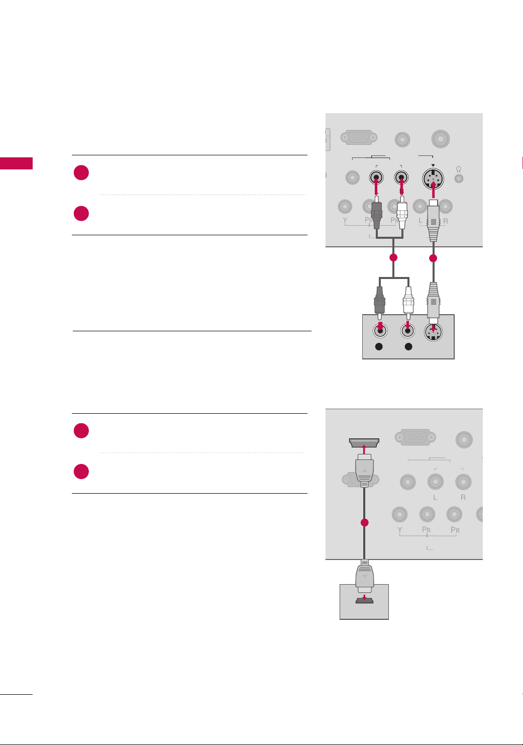
S-Video Connection
(Except 22/
26/32LF15R
1. How to connect
Connect the S-VIDEO output of the DVD to the
1
VVIIDDEE OO
input on the TV.
Connect the audio outputs of the DVD to the
2
input jacks on the TV.
2. How to use
■
Turn on the DVD player, insert a DVD.
■
Select the
AA VV
input source on the TV using the
button on the remote control.
■
Refer to the DVD player's manual for operating instructions.
HDMI Connection
1. How to connect
)
AAUUDDIIOO
II NN PP UUTT
SS --
2
1
24
2. How to use
Connect the HDMI output of the DVD to the
1
IINN orHHDDMMII IINN((FFoorr 2222//
26/32LF15R)
HHDDMMII//DDVVII
jack on the TV.
No separated audio connection is necessary.
2
HDMI supports both audio and video.
■
Select the
input source on the TV using the
remote control.
■
Refer to the DVD player's manual for operating instructions.
HHDDMMII //DDVV IIorHHDDMMII ((FFoorr 2222//
II NN PP UUTT
26/32LF15R)
button on the
1
 Loading...