

Page 1

OWNER’S MANUAL
LCD TV / LED LCD TV
Please read this manual carefully before operating
your set and retain it for future reference.
P/NO: MFL63724108(1005-REV00)
Printed in Thailand
www.lg.com
Page 2
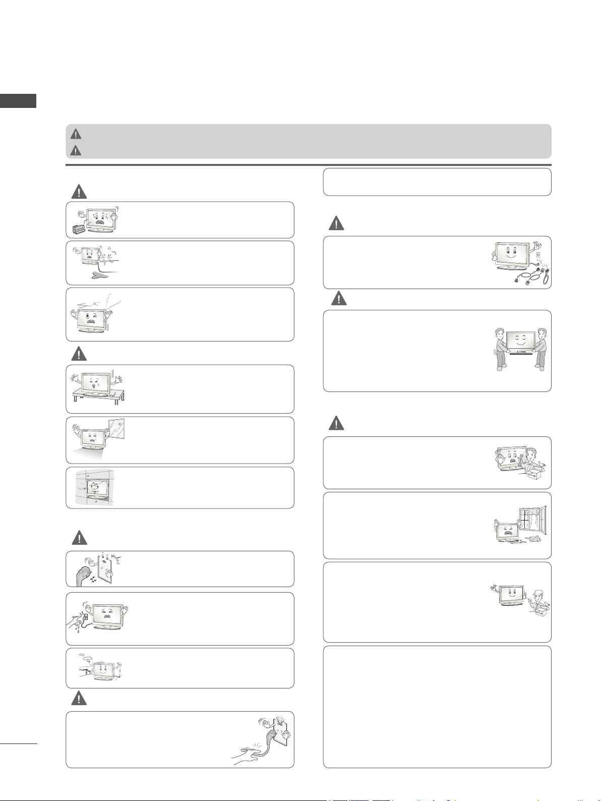
SAFETY INSTRUCTIONS
• Please read these safety precautions carefully before using the product.
ENGLISH
• In this manual, the illustration may be somewhat different from your product because it is just example to help the instruction.
WARNING
CAUTION
If you ignore the warning message, you may be seriously injured or there is a possibility of accident or death.
If you ignore the caution message, you may be slightly injured or the product may be damaged.
PRECAUTION IN INSTALLING THE PRODUCT
WARNING
Keep away from heat sources like electrical
heaters.
- Electrical shock, fire, malfunction or deformation may occur.
Do not use the product in damp place such as
a bathroom or any place where it is likely to get
wet.
- This may cause a fire or could give an electric
shock.
If you can smell smoke or other odors or hear
a strange sound unplug the power cord and
contact the service center.
- If you continue to use without taking proper
measures, electrical shock or fire can occur.
CAUTION
Install the product on a flat and stable place
that has no risk of dropping the product.
- If the product is dropped, you may be
injured or the product may be broken.
Keep the product away from direct sunlight.
- The product can be damaged.
Do not place the product in a built-in installation such as bookcase or rack.
- Ventilation required.
ELECTRICAL POWER RELATED PRECAUTIONS
WARNING
Make sure to connect the power cable to the
grounded current.
- You may be electrocuted or injured.
Do not touch the power plug with wet hands.
Additionally, it the cord pin is wet or covered
with dust, dry the power plug completely or
wipe dust off.
- You may be electrocuted due to excess
moisture.
During a thunder or lightning storm, unplug
the power cable or signal cable.
- You may be electrocuted or a fire can break
out.
CAUTION
Protect the power cord from physical or
mechanical abuse, such as being twisted,
kinked, pinched, closed in a door, or walked
upon. Pay particular attention to plugs, wall
outlets, and the point where the cord exits
the appliance.
2
As long as this unit is connected to the AC wall outlet, it is not
disconnected from the AC power source even if you turn off
this unit by SWITCH.
PRECAUTIONS IN MOVING THE PRODUCT
WARNING
Make sure to turn off the product.
Make sure to remove all cables before mov-
ing the product.
- You may be electrocuted or the product
can be damaged.
CAUTION
Do not shock the product when moving it.
- You may be electrocuted or the product
can be damaged.
Make the panel face forward and hold it
with both hands to move.
- If you drop the product, the damaged
product can cause electric shock or fire.
Contact with the service center for repair.
PRECAUTIONS IN USING THE PRODUCT
WARNING
Do not disassemble, repair or modify the
product at your own discretion.
- Fire or electric shock accident can occur.
- Contact the service center for check, calibration or repair.
To reduce the risk of fire or electric shock,
do not expose this apparatus to rain or
moisture.
Apparatus shall not be exposed to dripping
or splashing and no objects filled with liquids, such as vases, shall be placed on the
apparatus.
Refer all servicing to qualified service personnel. Servicing is required when the
apparatus has been damaged in any way,
such as power supply cord or plug is damaged, liquid has been spilled or objects
have fallen into the apparatus, the apparatus has been exposed to rain or moisture,
does not operate normally, or has been
dropped.
IMPORTANT INFORMATION TO PREVENT “IMAGE BURN /
BURN-IN” ON YOUR TELEVISION SCREEN
-
When a fixed image (e.g. logos, screen menus, video game,
computer display and teletext pages) is displayed on the television for an extended period it can become permanently imprinted on the screen. This phenomenon is known as “image burn” or
“burn-in”. Image burn is not covered under the manufacturer’s
warranty.
-
In order to prevent image burn, avoid displaying a fixed image on
your television’s screen for a prolonged period (2 or more hours
for LCD, 1 or more hours for Plasma).
-
Image burn can also occur on the letterboxed areas of your
television if you use the 4:3 aspect ratio setting for an extended
period.
Page 3
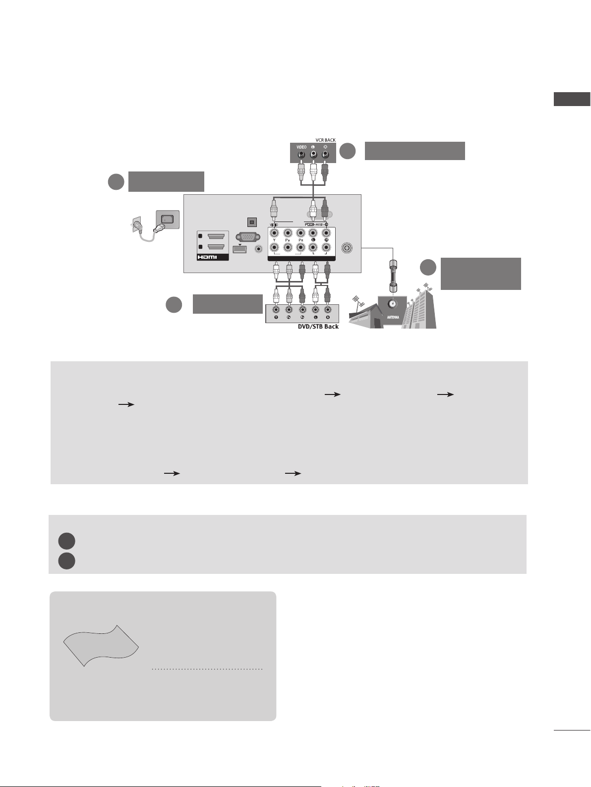
CONNECTING YOUR UNIT
■ Image shown may differ from your TV.
■ To connect an additional equipment, see the External equipment Setup section in CD Manual.
VCR Connection
2
Power Cord
3
RS-232C IN
AV IN1
VIDEO
COMPONENT IN
COMPONENT IN
(CONTROL & SERVICE)
R
AUDIO
L/MONO
AUDIO
2
1
ANTENNA /
CABLE IN
Antenna
1
Connection
OPTICAL
DIGITAL
AUDIO OUT
(PC)
AUDIO IN
(RGB/DVI)
VIDEO
/DVI IN
RGB IN
WIRELESS
CONTROL
2
1
ENGLISH
2
DVD/STB
TO VIEW THE USER'S GUIDE ON THE CD-ROM
To view the User's guide on the CD-ROM, Adobe Acrobat Reader must be installed on your PC.
The "ACRORD" folder on the CD-ROM contains the installation program for Acrobat Reader.
If you want to install Acrobat Reader, Open "My Computer" Open the folder "LG" Open the folder
"ACRORD" double-click your language.
To view the User's guide
The User's guide files are included in the supplied CD-ROM.
Load the supplied CD-ROM into the CD-ROM drive of your PC.
After a while, the web page of the CD-ROM will open automatically.(Windows users only)
If the web page does not appear automatically, open the User's guide file directly.
Open "My computer" Open the folder "LG" Double click the "index.htm" file.
TO VIEW THE SIMPLE MANUAL
You can easily and effectively access the TV information by viewing the simple manual on the TV.
Press the GREEN button, you can check the Simple manual menu.
1
Press the EXIT button to return to normal TV viewing.
2
This item is not included for all models.
* Lightly wipe any stains
or fingerprints on the
surface of the TV with
the polishing cloth.
Polishing Cloth
Polishing cloth for
use on the screen.
Do not use excessive
force. This may cause
scratching or discolouration.
3
Page 4
PREPARATION
LIGHT
ENGLISH
ACCESSORIES
Ensure that the following accessories are included with your TV. If an accessory is missing, please
contact the dealer where you purchased the TV.
ENERGY
SAVING
1 2 3
4 506
7 8 9
LIST
MENU
BACK
■ Image shown may differ from your TV.
Batteries
Owner’s Manual
AV MODE
INPUT
AV MODE
INPUT
Q.VIEW
MARK
FAV
RATIO
P
MUTE
GUIDE
Q.MENU
OK
EXIT
INFO i
SUBTITLE
ENERGY
SAVING
1 2 3
4 506
7 8 9
LIST
MENU
BACK
AD
TV/
RAD
Q.VIEW
MARK
FAV
RATIO
P
MUTE
GUIDE
Q.MENU
OK
EXIT
INFO i
SUBTITLE
TV/
RAD
or
P
A
G
E
AV MODE
ENERGY
SAVING
1 2 3
GHI
4 506
7 8 9
PQRS
LIST
or
P
A
G
E
MENU
BACK
INFO i
(AAA)
AV MODE
INPUT
INPUT
ABC
JKL
TUV
Q.VIEW
MARK
FAV
CHAR/NUM
RATIO
DELETE
MUTE
Q.MENU
OK
GUIDE
EXIT
SUBTITLE
ENERGY
SAVING
1 2 3
JKL
GHI
4 506
7 8 9
PQRS
LIST
MARK
FAV
CHAR/NUM
3D
DELETE
MUTE
MENU
OK
GUIDE
BACK
RATIO
INFO i
TV/
RAD
DEF
ABC
MNO
WXYZ
TUV
Q.VIEW
or
P
A
P
G
E
Q.MENU
EXIT
L/R SELECT
TV/
RAD
DEF
MNO
WXYZ
or
P
A
P
G
E
Remote Control
AV MODE
ENERGY
SAVING
1 2 3
JKL
GHI
4 506
7 8 9
PQRS
LIST
MARK
FAV
CHAR/NUM
3D
DELETE
MUTE
MENU
OK
GUIDE
BACK
RATIO
INFO i
1-screw for stand fixing
(Refer to p. 21)
LIGHT
INPUT
TV/
RAD
DEF
ABC
MNO
WXYZ
TUV
Q.VIEW
P
A
P
G
E
Q.MENU
(Only 26/32LD3**, 32/37/42LD4**,
32/42LD5**, 32/37/42LD6**, 32/42LE4***,
32LE5***)
(Except for
32/37/42/47/55/60LE5***,
EXIT
L/R SELECT
32/37/42/47/55LE7***,
42/47/55LE8***,
Power Cord
42/47/55LX6***, 47/55LX9***)
Only 22LD3**
Cable Holder
(Refer to p. 20)
Only 32/37/42/47LD4**
x 8
(M4 X 20)
Bolts for stand assembly
(Refer to p. 17)
Only 22/26LE53**
x 4
Protection Cover
(Refer to p. 22)
Protection Cover
(Refer to p. 22)
x 4
Only 26/32LD3**
x 8
(M4 X 20)
Bolts for stand assembly
(Refer to p. 17)
Only 32/42/46/52/60LD5**
x 8
(M4 X 20)
Bolts for stand assembly
(Refer to p. 17)
Protection Cover
(Refer to p. 22)
Protection Cover
(Refer to p. 22)
(Only 32/42/52LD56*)
Nero MediaHome
4 Essentials CD
(M4x14)
Bolts for stand assembly
4
(Refer to p. 18)
(M4x20)
(Only 26LE53**)
Cable Holder
(Refer to p. 21)
AC/DC Adaptor
(Refer to p. 23)
4-Ring spacers
(Only 26LE53**)
(Refer to p. 23)
Page 5
Only 32/37/42/47/55LE53
**
x 4
(M4x22)
(Only 32LE53**)
x 4
(M4x24)
(Only
37/42LE53**)
x 4
(M4x26)
(Only
47/55LE53**)
x 4
(M4x16)
Component gender cable,
AV gender cable
x 2
Bolts for stand assembly (Refer to p. 18)
Cable Holder
(Refer to p. 21)
Only 32/37/42/47/55LD6**
x 8
(M4x20)
Bolts for stand assembly
(Refer to p. 17)
Protection cover
(Refer to p. 22)
Nero MediaHome
4 Essentials CD
Only 32/37/42/47/55/60LE55**, 32/37/42/47/55LE7***, 42/47/55LE8***, 42/47/55LX6***, 47/55LX9***
(Only 32/37/42/47LE55**,
32/37/42/47LE7
42/47LX6***)
***,
x 8
(M4 x 16)
Bolts for stand assembly
(Only 42/47/55LE8
x 8
(M4 x 20)
(Refer to p. 19)
***
)
(Only 55LE55**,
55LE7
***,
55LX6***)
x 4x 4
(M4 x 16)(M4 x 24)
(Only 47/55LX9***)
x 4
M4x12
x 4
M4x22
Bolts for stand assembly
(Refer to p. 20)
ENGLISH
cleansing cloths(mitt)
(Only 32/37/42/47/55LE7
***
)
Slightly wipe stained spot on the exterior only with
the cleansing cloths(mitt) for the product exterior if
there is stain or fingerprint on surface of the exterior.
For cleaning front frame, please slowly wipe in one
direction after spraying water 1~2 times on cleansing
cloths. Please remove excessive moisture after cleaning.
Excessive moisture may cause water stains on the frame.
(Only 42/47/55LX6
***
)
(Only 47/55LX9***)
x 2
3D Glasses
3D Glasses
Stand Rear Cover
Cable Holder
(Refer to p. 21)
Nero MediaHome
4 Essentials CD
Component gender cable,
AV gender cable
x 2
5
Page 6
P
INPUT
MENU
OK
P
INPUT
MENU
OK
P
INPUT
MENU
OK
P
P
OK
MENU
INPUT
P
INPUT
MENU
PREPARATION
ENGLISH
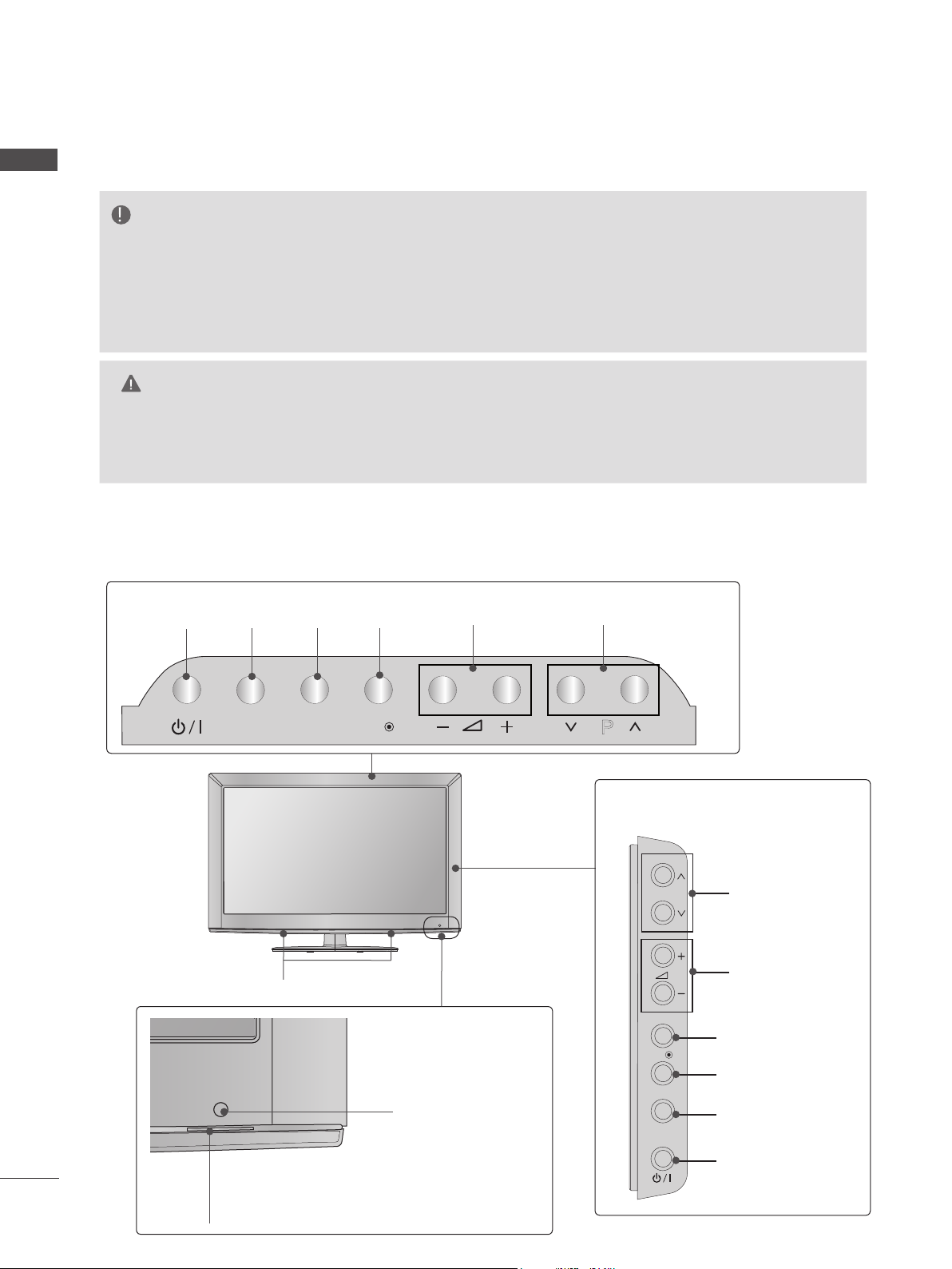
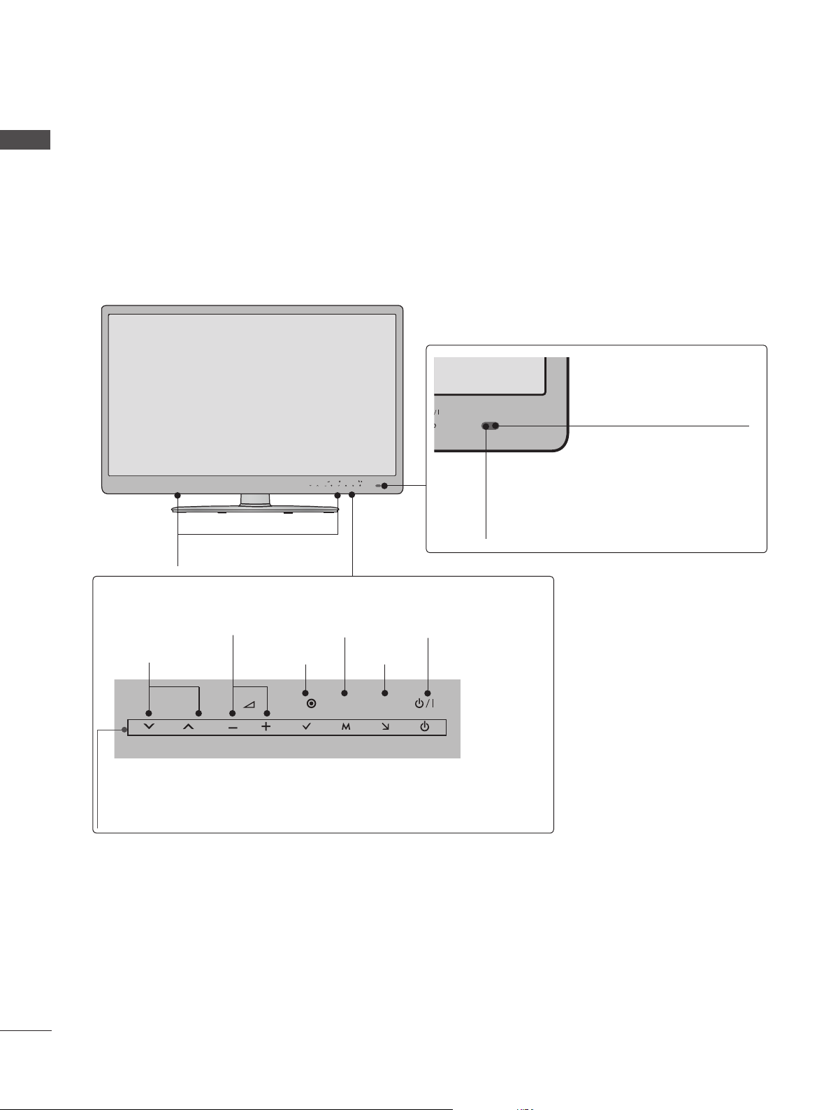
FRONT PANEL CONTROLS
■ Image shown may differ from your TV.
Only 22/26/32LD3**
NOTE
►
TV can be placed in standby mode in order to reduce the power consumption. And TV should
be switched off using the power switch on the TV if it will not be watched for some time, as this
will reduce energy consumption.
► The energy consumed during use can be significantly reduced if the level of brightness of the picture
is reduced, and this will reduce the overall running cost.
CAUTION
► Do not step on the glass stand or subject it to any impact. It may break, causing possible injury from frag-
ments of glass, or the TV may fall.
► Do not drag the TV. The floor or the product may be damaged.
Only 22LD3**
INPUTPOWER
OKMENU
PROGRAMMEVOLUME
INPUT
MENU
OK
P
Only 26/32LD3**
P
SPEAKER
Remote Control Sensor
OK
MENU
INPUT
Power/Standby Indicator
(Can be adjusted using the Power
6
Indicator in the OPTION menu.)
PROGRAMME
VOLUME
OK
MENU
INPUT
POWER
Page 7
OK
P
P
OK
P
MENU
INPUT
■ Image shown may differ from your TV.
OK
P
MENU
INPUT
Only 32/37/42/47LD4**
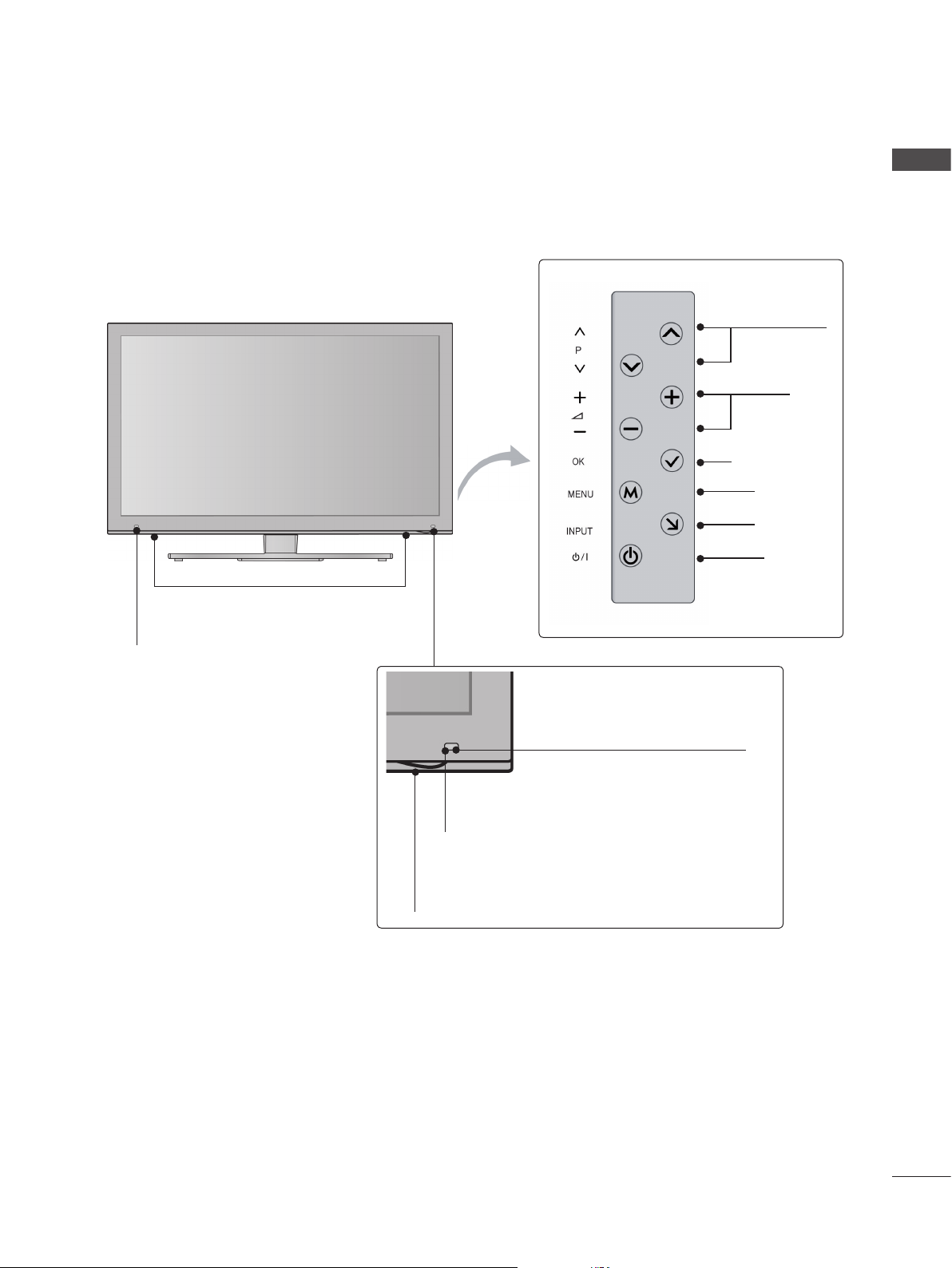
ENGLISH
SPEAKER
Power/Standby Indicator
(Can be adjusted using the Power
Indicator in the OPTION menu.)
Only 32/42/46/52/60LD5**
Remote Control Sensor
OK
MENU
INPUT
P
PROGRAMME
VOLUME
OK
MENU
INPUT
POWER
SPEAKER
Power/Standby Indicator
(Can be adjusted using the Power
Indicator in the OPTION menu.)
PROGRAMME
P
VOLUME
OK
MENU
INPUT
OK
MENU
INPUT
POWER
Remote Control Sensor
Intelligent Sensor
Adjusts picture according to
the surrounding conditions.
7
Page 8
PREPARATION
INPUT
MENU
OK
P
INPUT
MENU
OK
P
■ Image shown may differ from your TV.
ENGLISH
Only 32/37/42/47/55LD6**
SPEAKER
Power/Standby Indicator
(Can be adjusted using the Power Indicator in the
OPTION menu.)
Remote Control Sensor
Intelligent Sensor
Adjusts picture according to the surrounding conditions.
P
OK
MENU
INPUT
PROGRAMME
VOLUME
OK
MENU
INPUT
POWER
■ Image shown may differ from your TV.
Only 22/26LE53**
P
OK
SPEAKER
VOLUME MENU POWER
P
OK
MENU
INPUT
OKPROGRAMME
INPUT
Power/Standby Indicator
(Can be adjusted using the
Power Indicator in the
OPTION menu.)
MENU
INPUT
U
INPUT
Remote Control Sensor
8
Page 9
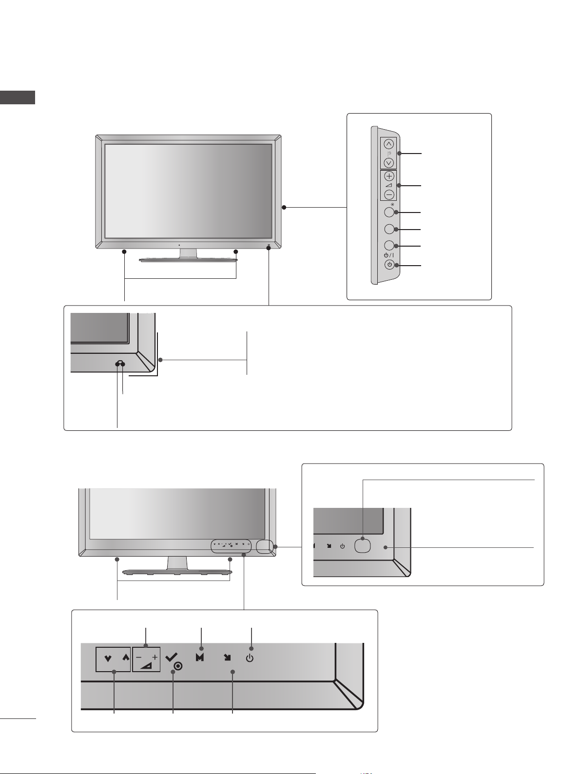
■ Image shown may differ from your TV.
Only 32/37/42/47/55/60LE5***, 32/37/42/47/55LE7***, 42/47/55LX6***
P
MENU
OK
INPUT
ENGLISH
Intelligent Sensor
Adjusts picture according to
the surrounding conditions.
SPEAKER
Emitter (Only 42/47/55LX6
***
)
It is the part equipped with the emitter
exchanging signal with 3D glasses.
Please be careful not to block
the screen with objects or people
while watching a 3D Video.
Touch Sensor
• You can use the desired button function by touching.
INPUTOK
P
PROGRAMME
VOLUME
OK
MENU
MENU
INPUT
POWER
Remote Control Sensor
Power/Standby Indicator
(Can be adjusted using the Power
Indicator in the OPTION menu.)
9
Page 10
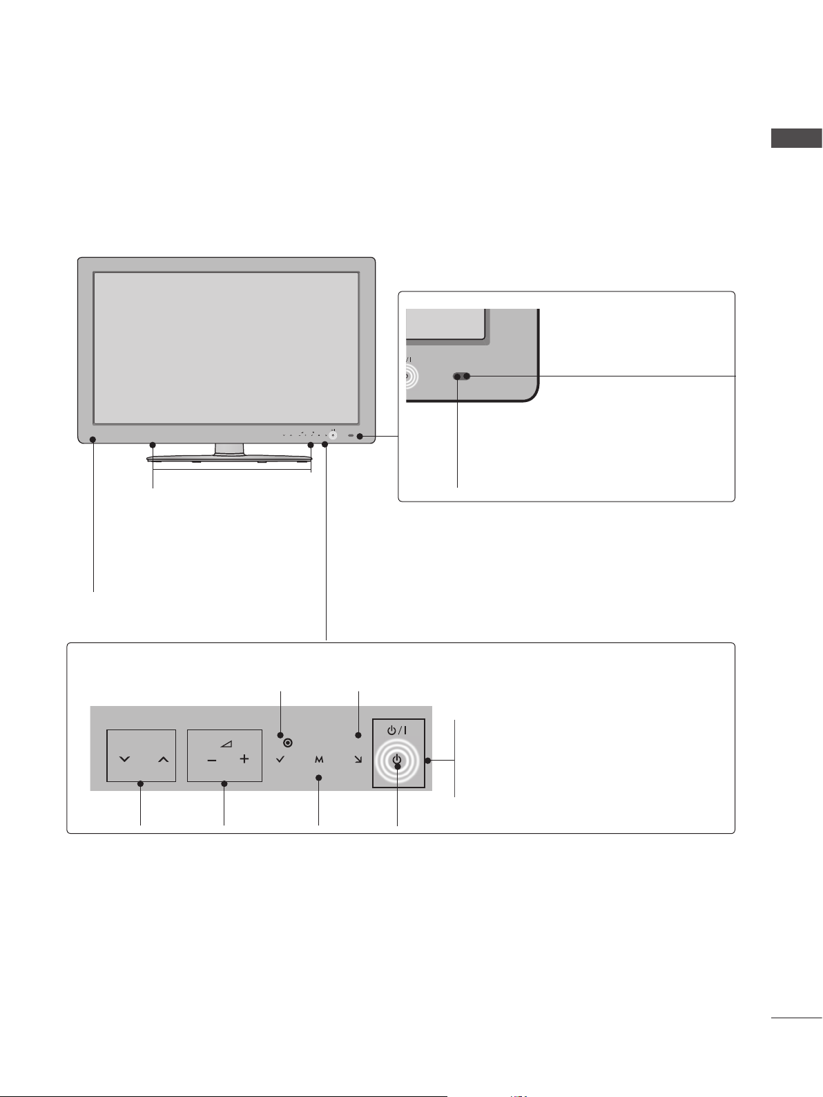
ENGLISH
Only 42/47/55LE8***
■ Image shown may differ from your TV.
MENU
P
OK
SPEAKER
Intelligent Sensor
Adjusts picture according to
the surrounding conditions.
INPUT
Remote Control Sensor
Touch Sensor
• You can use the desired button function by touching.
PROGRAMME
P
VOLUME
OK
MENU
MENU
POWER
INPUTOK
INPUT
Power/Standby Indicator
(Can be adjusted using the Power Indicator in the OPTION
menu.)
10
Page 11
■ Image shown may differ from your TV.
Only 47/55LX9***
SPEAKER
ENGLISH
PROGRAMME
VOLUME
OK
MENU
INPUT
POWER
Emitter
It is the part equipped with the
emitter exchanging signal with 3D
glasses.
Please be careful not to block
the screen with objects or
people while watching a 3D
Video.
Intelligent Sensor
Adjusts picture according to
the surrounding conditions.
Remote Control Sensor
Power/Standby Indicator
(Can be adjusted using the Power Indicator
in the OPTION menu.)
11
Page 12
PREPARATION
H/P
AV IN2
IN 2
SERVICE ONLY
K
AC-IN
H/P
SERVICE ONLY
ENGLISH
BACK PANEL INFORMATION
Only 22LD3**
Only 26/32LD3**
■ Image shown may differ from your TV.
2
/DVI IN
RGB IN
(PC)
2
1
3 4 5 6
(CONTROL & SERVICE)
OPTICAL
AUDIO IN
DIGITAL
AUDIO OUT
1
3 5
RGB IN
(RGB/DVI)
OPTICAL
DIGITAL
AUDIO OUT
(PC)
8
VIDEO
VIDEO
COMPONENT IN
AC IN
CABLE MANAGEMENT
VIDEO
RS-232C IN
AUDIO
L(MONO)
AUDIO
6
RS-232C IN
(CONTROL & SERVICE)
AV IN 1
L/MONO
R
AV IN
ANTENNA /
CABEL IN
10
IN 2
H/P
H/P
SERVICE ONLY
11
12
SERVICE ONLY
2
11
7
9
7
12
1
/DVI IN
1
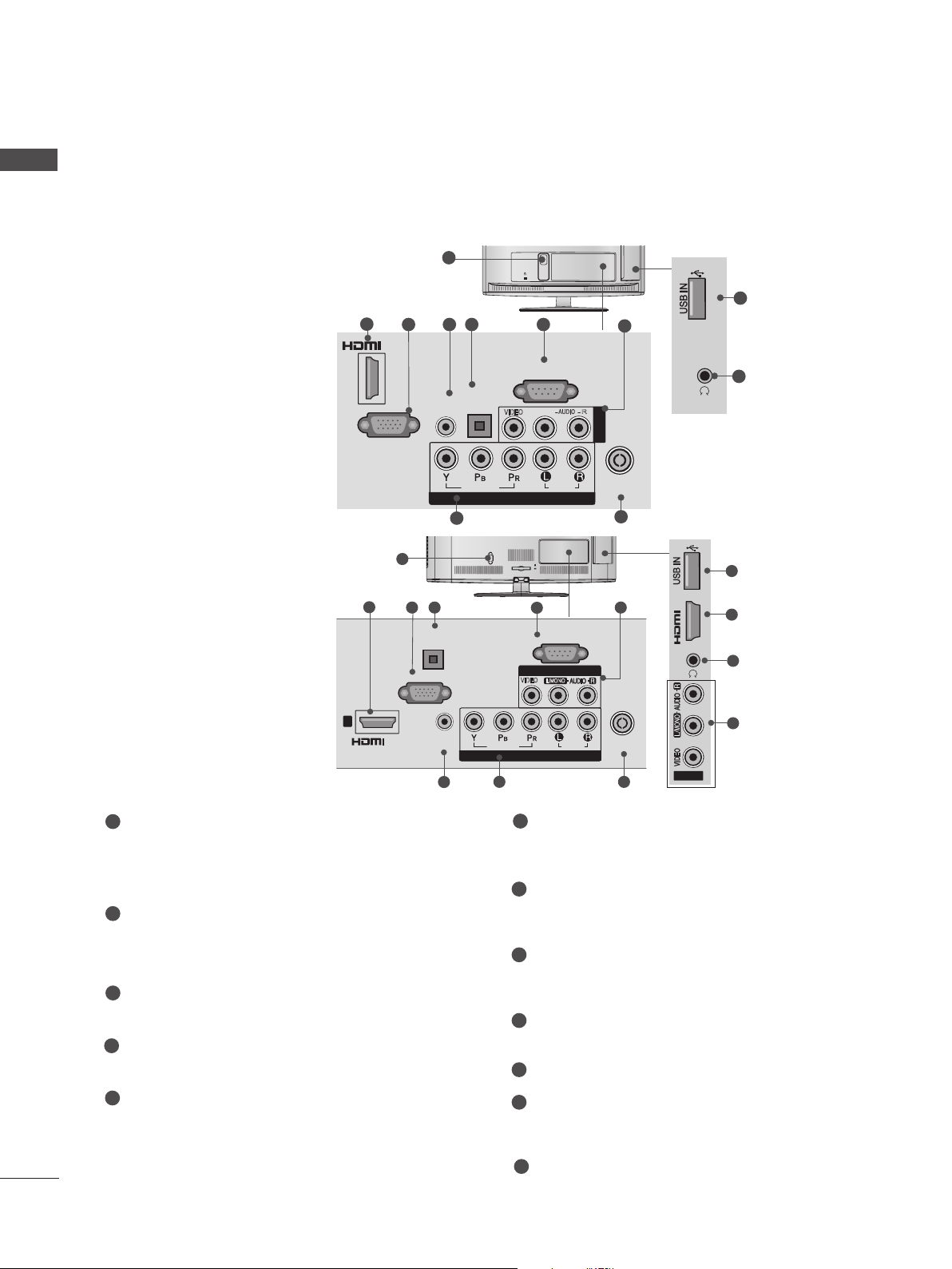
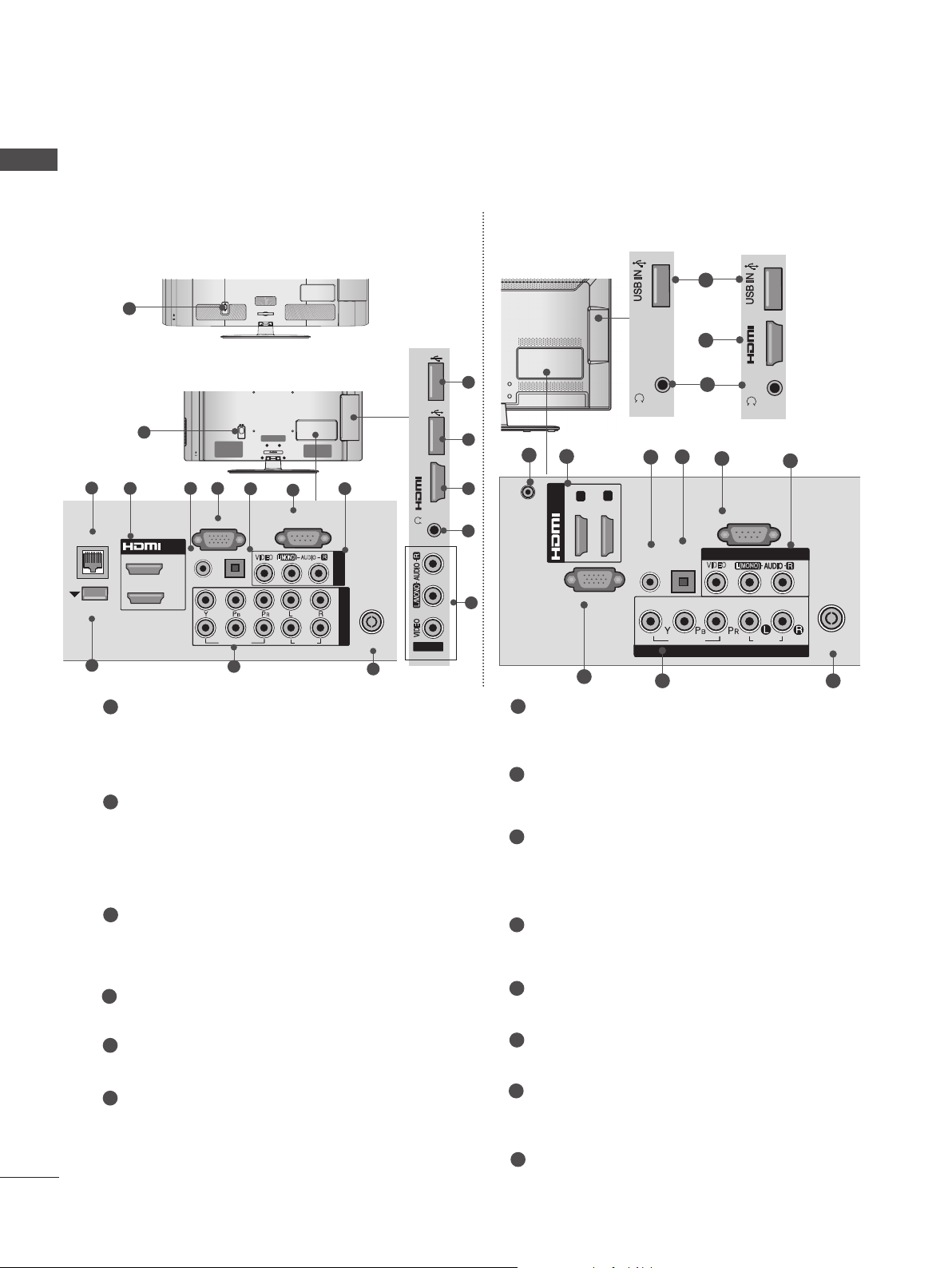
Power Cord Socket
This TV operates on an AC power. The voltage is indicated on the Specifications page.
Never attempt to operate the TV on DC
power.
2
HDMI/DVI IN Input
Connect an HDMI signal to HDMI IN. Or DVI
(VIDEO) signal to HDMI/DVI port with DVI to
HDMI cable.
3
RGB IN Input
Connect the output from a PC.
4
RGB/DVI Audio Input
Connect the audio from a PC or DTV.
5
OPTICAL DIGITAL AUDIO OUT
Connect digital audio to various types of
equipment.
AUDIO IN
(RGB/DVI)
4
ANTENNA /
VIDEO
COMPONENT IN
8
AUDIO
CABLE IN
9
6
RS-232C IN (CONTROL & SERVICE) PORT
AV IN2
Connect to the RS-232C port on a PC.
This port is used for Service or Hotel mode.
7
Audio/Video Input
Connect audio/video output from an external
device to these jacks.
8
Component Input
Connect a component video/audio device to
these jacks.
9
Antenna / Cable Input
Connect antenna or cable to this jack.
10
SERVICE ONLY PORT
11
Headphone Socket
Plug the headphone into the headphone
socket.
7
Connect to a Digital Audio Component.
Use an Optical audio cable.
12
USB Input
Connect USB storage device to this jack.
Page 13
■ Image shown may differ from your TV.
IN 3
H/P
R
AUDIO
HDMI IN 2 USB IN
H/P
H/P
AV IN2
IN 2
Only 32/37/42/47LD4**
ENGLISH
1
11
2
1
/DVI IN
Only 32/42/46/52/60LD55*
1
2
2
1
/DVI IN
1
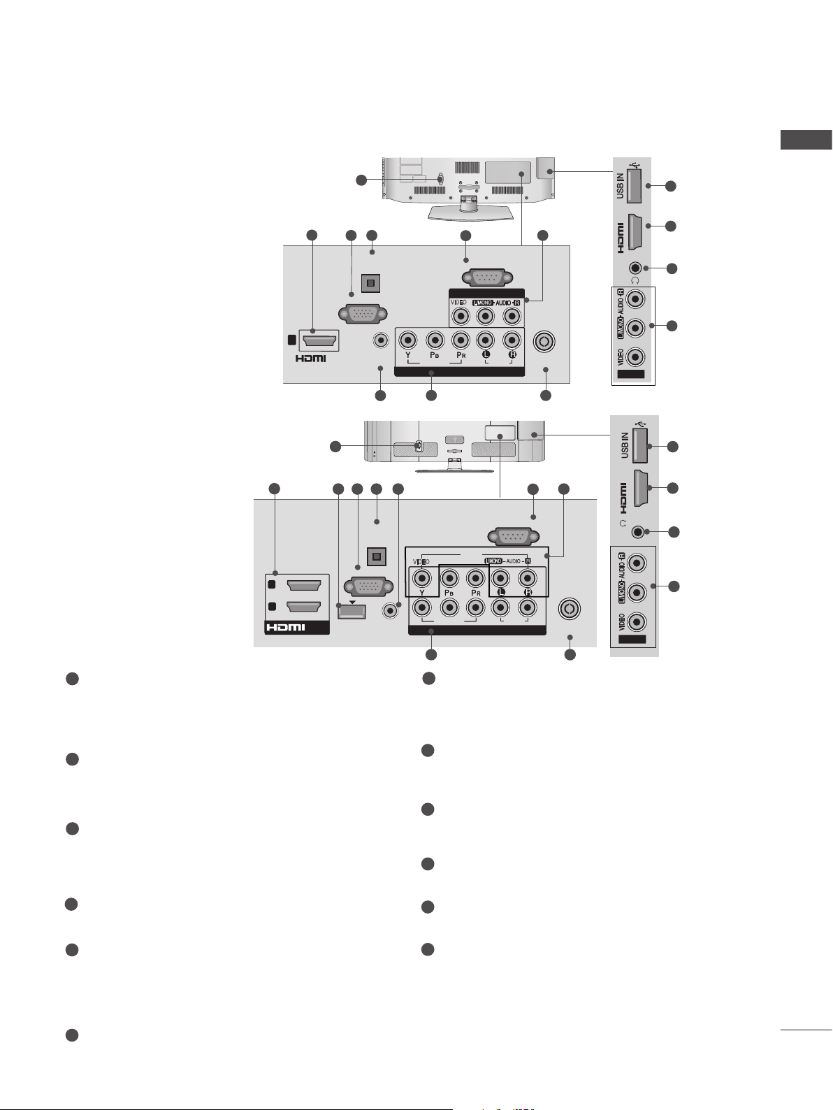
Power Cord Socket
This TV operates on an AC power. The voltage is indicated on the Specifications page.
Never attempt to operate the TV on DC
power.
2
HDMI/DVI IN Input
Connect an HDMI signal to HDMI IN. Or DVI
(VIDEO) signal to HDMI/DVI port with DVI to
HDMI cable.
3
WIRELESS Control
Connect the Wireless Dongle to the TV to
control the external input devices connected
to Media Box wirelessly.
4
RGB IN Input
Connect the output from a PC.
4 5
OPTICAL
DIGITAL
AUDIO OUT
RGB IN
(PC)
AUDIO IN
(RGB/DVI)
6
3 4 5 6
OPTICAL
DIGITAL
AUDIO OUT
RGB IN
(PC)
WIRELESS
AUDIO IN
CONTROL
(RGB/DVI)
IN 2
7
RS-232C IN
(CONTROL & SERVICE)
AV IN 1
VIDEO
L/MONO
VIDEO
COMPONENT IN
9
AC IN
VIDEO
VIDEO
9
7
RS-232C IN (CONTROL & SERVICE) PORT
AUDIO
CABLE MANAGEMENT
(CONTROL & SERVICE)
AV IN1
L/MONO
COMPONENT IN
COMPONENT IN
RS-232C IN
AUDIO
AUDIO
8
ANTENNA /
CABLE IN
10
7
R
2
1
8
ANTENNA /
CABLE IN
10
H/P
AV IN2
IN 3
H/P
AV IN2
Connect to the RS-232C port on a PC.
This port is used for Service or Hotel mode.
8
Audio/Video Input
Connect audio/video output from an external
device to these jacks.
9
Component Input
Connect a component video/audio device to
these jacks.
10
Antenna / Cable Input
Connect antenna or cable to this jack.
11
USB Input
Connect USB storage device to this jack.
2
12
8
11
2
12
8
5
OPTICAL DIGITAL AUDIO OUT
Connect digital audio to various types of
equipment.
Connect to a Digital Audio Component.
Use an Optical audio cable.
6
RGB/DVI Audio Input
Connect the audio from a PC or DTV.
12
Headphone Socket
Plug the headphone into the headphone
socket.
13
Page 14
PREPARATION
H/P
IN 3
H/P
IN 3
H/P
HDMI IN 3 USB IN 1
USB IN 2
h}GpuY
puGZ
H/P
USB IN 1
USB IN 2
ENGLISH
Only 32/42/52LD56*, 32/37/42/47/55LD6**
2
LAN
WIRELESS
CONTROL
9
1
2
3
■ Image shown may differ from your TV.
1
AC IN
CABLE MANAGEMENT
or
USB IN 2
RGB IN
(PC)
OPTICAL DIGITAL
AUDIO OUT
VIDEO
10
AC IN
6
VIDEO
CABLE MANAGEMENT
7
RS-232C IN
(CONTROL & SERVICE)
R
AUDIO
L(MONO)
AUDIO
AV IN 1
2
1
8
COMPONENT IN
ANTENNA /
CABLE IN
11
USB IN 1
puGZ
H/P
h}GpuY
1
3 54
/DVI IN
2
1
RGB/DVI
AUDIO IN
Power Cord Socket
This TV operates on an AC power. The voltage is indicated on the Specifications page.
Never attempt to operate the TV on DC
power.
LAN
Network connection for Weather info, Photo
Album, Movie Online, etc.
Also used for video, photo and music files on
a local network.
HDMI/DVI IN Input
Connect an HDMI signal to HDMI IN. Or DVI
(VIDEO) signal to HDMI/DVI port with DVI to
HDMI cable.
Only 22/26LE53**
12
12
14
3
13
8
DC-IN
7
RS-232C IN (CONTROL & SERVICE) PORT
Connect to the RS-232C port on a PC.
This port is used for Service or Hotel mode.
8
Audio/Video Input
Connect audio/video output from an external
device to these jacks.
9
WIRELESS Control
Connect the Wireless Dongle to the TV to
control the external input devices connected
to Media Box wirelessly.
10
Component Input
Connect a component video/audio device to
these jacks.
H/P
Only 22LE53**
/DVI IN
3
(DVI)
RGB IN
1
5
2
(PC)
4
AUDIO IN
(RGB/DVI)
12
2
13
IN 3
H/P
Only 26LE53**
6
7
RS-232C IN
(CONTROL & SERVICE)
OPTICAL
DIGITAL
VIDEO
AUDIO OUT
VIDEO
COMPONENT IN
10 11
L(MONO)
AV IN
AUDIO
8
ANTENNA /
CABLE IN
14
4
RGB/DVI Audio Input
Connect the audio from a PC or DTV.
5
RGB IN Input
Connect the output from a PC.
6
OPTICAL DIGITAL AUDIO OUT
Connect digital audio to various types of
equipment.
Connect to a Digital Audio Component.
Use an Optical audio cable.
11
Antenna / Cable Input
Connect antenna or cable to this jack.
12
USB Input
Connect USB storage device to this jack.
13
Headphone Socket
Plug the headphone into the headphone
socket.
14
DC ADAPTER PORT
Connect to the power cord socket.
Page 15
■ Image shown may differ from your TV.
H/P
USB IN
/ AUDIO
IN 4
Y PB PR
USB IN 2
USB IN 1
Only 32/37/42/47/55LE53**
1
ENGLISH
CAUTION
USB IN
2
12
IN 4
H/P
11
► Use a product with the follow-
ing thickness for optimal connection to HDMI cable(only
HDMI IN 4) / USB device.
*A 10 mm
2 43
OPTICAL
/DVI IN
3
2
1
(DVI)
1
Power Cord Socket
DIGITAL
AUDIO OUT
RGB IN
WIRELESS
CONTROL
7 9
(PC)
AUDIO IN
(RGB/DVI)
8
COMPONENT IN1
VIDEO
5
RS-232C IN
(CONTROL & SERVICE)
AV IN 1
L(MONO)
VIDEO
AUDIO
AUDIO
This TV operates on an AC power. The voltage is indicated on the Specifications page.
Never attempt to operate the TV on DC
power.
HDMI/DVI IN Input
2
Connect an HDMI signal to HDMI IN. Or DVI
(VIDEO) signal to HDMI/DVI port with DVI to
HDMI cable.
3
RGB IN Input
Connect the output from a PC.
OPTICAL DIGITAL AUDIO OUT
4
Connect digital audio to various types of
equipment.
Connect to a Digital Audio Component.
Use an Optical audio cable.
5
RS-232C IN (CONTROL & SERVICE) PORT
Connect to the RS-232C port on a PC.
This port is used for Service or Hotel mode.
R
6
9
ANTENNA /
CABLE IN
10
/ AUDIO
Y PB PR
COMPONENT IN2
7
WIRELESS Control
Connect the Wireless Dongle to the TV to
control the external input devices connected
to Media Box wirelessly.
8
RGB/DVI Audio Input
Connect the audio from a PC or DTV.
9
Component Input
Connect a component video/audio device to
these jacks.
10
Antenna / Cable Input
Connect antenna or cable to this jack.
11
USB Input
Connect USB storage device to this jack.
Headphone Socket
12
Plug the headphone into the headphone
socket.
AV IN2
VIDEO / AUDIO
6
6
Audio/Video Input
Connect audio/video output from an external
device to these jacks.
15
Page 16

PREPARATION
USB IN 2
USB IN 1
USB IN 2
USB IN 1
COMPONENT IN3
AUDIO / Y P
B
P
R
ENGLISH
Only 32/37/42/47/55/60LE55**, 32/37/42/47/55LE7***, 42/47/55LE8***,
42/47/55LX6***, 47/55LX9***
2
LAN
WIRELESS
CONTROL
9
■ Image shown may differ from your TV.
1
3 54
/DVI IN
3
2
1
RGB IN
(RGB/DVI)
AUDIO IN
2
1
(PC)
OPTICAL DIGITAL
AUDIO OUT
VIDEO
10
6
(CONTROL & SERVICE)
VIDEO
7
RS-232C IN
L(MONO)
AUDIO
AUDIO
R
8
AV IN 1
COMPONENT IN
ANTENNA/
CABLE IN
13
CAUTION
► Use a product with the follow-
ing thickness for optimal connection to HDMI cable(only
HDMI IN 4) / USB device.
11
USB IN 2
USB IN 1
B PR
10
COMPONENT IN3
AUDIO / Y P
12
3
H/P
IN 4
*A 10 mm
8
AV IN2
VIDEO / AUDIO
1
Power Cord Socket
This TV operates on an AC power. The voltage is indicated on the Specifications page.
Never attempt to operate the TV on DC
power.
2
LAN
Network connection for Weather info, Photo
Album, Movie Online, etc.
Also used for video, photo and music files on
a local network.
3
HDMI/DVI IN Input
Connect an HDMI signal to HDMI IN. Or DVI
(VIDEO) signal to HDMI/DVI port with DVI to
HDMI cable.
4
RGB/DVI Audio Input
Connect the audio from a PC or DTV.
5
RGB IN Input
Connect the output from a PC.
6
OPTICAL DIGITAL AUDIO OUT
Connect digital audio to various types of
equipment.
Connect to a Digital Audio Component.
Use an Optical audio cable.
7
RS-232C IN (CONTROL & SERVICE) PORT
Connect to the RS-232C port on a PC.
This port is used for Service or Hotel mode.
8
Audio/Video Input
Connect audio/video output from an external
device to these jacks.
9
WIRELESS Control
Connect the Wireless Dongle to the TV to
control the external input devices connected
to Media Box wirelessly.
10
Component Input
Connect a component video/audio device to
these jacks.
11
USB Input
Connect USB storage device to this jack.
12
Headphone Socket
Plug the headphone into the headphone
socket.
13
Antenna / Cable Input
Connect antenna or cable to this jack.
16
Page 17

M4X20
M4X20
M4X20
M4X20
M4X20
STAND INSTALLATION
■ Image shown may differ from your TV.
When assembling the desk type stand, check whether the bolt is fully tightened. (If not tightened fully,
the product can tilt forward after the product installation.) If you tighten the bolt with excessive force,
the bolt can deviate from abrasion of the tightening part of the bolt.
Only 22LD3**
Carefully place the TV screen side down
1
on a cushioned surface to protect the
screen from damage.
Assemble the TV as shown.
2
Only 26/32LD3**, 32/37/42/47LD4**,
32/42/46/52/60LD5**, 32/37/42/47/55LD6**
Carefully place the TV screen side down
1
on a cushioned surface to protect the
screen from damage.
Assemble the parts of the Stand Body with
2
the Stand Base of the TV.
Stand Body
ENGLISH
Assemble the TV as shown.
3
Fix the 4 bolts securely using the holes in
4
the back of the TV.
Stand Base
17
Page 18

PREPARATION
ENGLISH
■ Image shown may differ from your TV.
Only 22LE53**
Carefully place the TV screen side down
1
on a cushioned surface to protect the
screen from damage.
Assemble the parts of the Stand Body with
2
the Stand Base of the TV.
Stand Body
Stand Base
Only 26/32/37/42/47/55LE53**
Carefully place the TV screen side down
1
on a cushioned surface to protect the
screen from damage.
Assemble the parts of the Stand Body with
2
the Stand Base of the TV.
M4 X 22(Only 32LE53**)
M4 X 24 (Only 37/42LE53**)
M4 X 26 (Only 47/55LE53**)
M4 X 20
(Only 26LE53**)
Assemble the TV as shown.
3
Stand
Body
Stand
Base
Assemble the TV as shown.
3
Fix the 4 bolts securely using the holes in
4
the back of the TV.
M4 X 14
Assemble the parts of the Stand Rear
4
Cover with the TV.
Stand Rear
Cover
Fix the 4 bolts securely using the holes in
5
the back of the TV.
M4 X 14
(Only 26LE53**)
32/37/42/47/55LE53**)
M4 X 16 (Only
18
Page 19

■ Image shown may differ from your TV.
Only 32/37/42/47/55LE55**, 32/37/42/47/55LE7***, 42/47/55LE8***, 42/47/55LX6***
ENGLISH
Carefully place the TV screen side down
1
on a cushioned surface to protect the
screen from damage.
Assemble the parts of the Stand Body with
2
the Stand Base of the TV.
At this time, tighten the screws that hold the
Stand Body on.
M4 X 16
(Only 32/37/42/47LE55**,
32/37/42/47LE7
, 42/47LX6***)
***
M4 X 20
(Only 42/47/55LE8
***
Assemble the parts of the Stand Rear
4
Cover with the TV.
Stand Rear
Cover
Fix the 4 bolts securely using the holes in
5
the back of the TV.
)
M4 X 16
M4 X 20
M4 X 24
(Only 55LE55**,
55LE7***, 55LX6***)
Assemble the TV as shown.
3
Stand
Body
Stand
Base
(Only
32/37/42/47/55LE55**,
32/37/42/47/55LE7
42/47/55LX6***)
***
(Only 42/47/55LE8
,
***
)
19
Page 20

PREPARATION
K
AC-IN
AC IN
AC IN
AC IN
AC IN
Only 47/55LX9***
ENGLISH
1
2
3
Carefully place the TV screen side down
on a cushioned surface to protect the
screen from damage.
Assemble the parts of the Stand Body with
the Stand Base of the TV.
At this time, tighten the screws that hold the
Stand Body on.
Stand Body
M4 X 22
Stand Base
Fix the 4 bolts securely using the holes in
the back of the TV.
Only 26/32LD3**, 32/37/42/47LD4**,
32/37/42/47/55LD6**, 32/42/46/52/60LD5**
Connect the cables as necessary.
1
To connect additional equipment, see the
External equipment setup section.
AC IN
Open the Cable Management Clip as
2
shown and manage the cables.
AC IN
M4 X 12
Assemble the parts of the Stand Rear
4
Cover with the TV.
Stand Rear
Cover
BACK COVER FOR WIRE
ARRANGEMENT
■ Image shown may differ from your TV.
Only 22LD3**
After connecting the cables as necessary, install
Cable Holder as shown and bundle the cables.
Cable Management Clip
Fit the Cable management clip as shown.
3
AC IN
NOTE
►Do not use the CABLE MANAGEMENT CLIP
to lift the TV.
- If the TV is dropped, you may be injured or the
TV may be damaged.
AC-IN
K
20
Cable Holder
Page 21

■ Image shown may differ from your TV.
USB IN 2
USB IN 1
Only 22/26LE5***
After connecting the cables as necessary,
install Cable Holder as shown and bundle the
cables.
ATTACHING THE TV TO A
DESK
(Only 26/32LD3**, 32/37/42LD4**,
32/42LD5
32LE5***
■ Image shown may differ from your TV.
The TV must be attached to desk so it cannot be
pulled in a forward/backward direction, potentially causing injury or damaging the product. Use
only an attached screw.
**, 32/37/42LD6**, 32/42LE4***,
)
AC IN
CABLE MANAGEMENT
ENGLISH
Cable Holder
Only 32/37/42/47/55/60LE5***,
32/37/42/47/55LE7***, 42/47/55LE8***,
42/47/55LX6***, 47/55LX9***
Secure the power cord with the Cable
1
Holder on the TV back cover.
It will help prevent the power cable from
being removed by accident.
Cable Holder
After connecting the cables as necessary,
2
install Cable Holder as shown and bundle
the cables.
1-Screw ( provided as parts of the product)
Stand
Desk
WARNING
►To prevent TV from falling over, the TV
should be securely attached to the floor/wall
per installation instructions. Tipping, shaking,
or rocking the machine may cause injury.
Cable Holder
21
Page 22

PREPARATION
ENGLISH
NOT USING THE DESKTYPE STAND
When installing the wall-mounted unit, use the
protection cover.
Only 22LD3**
1
2
■ Image shown may differ from your TV.
Carefully place the TV screen side down
on a cushioned surface to protect the
screen from damage.
Loose the bolts from TV.
Only 26/32LD3**, 32/37/42/47LD4**,
32/42/46/52/60LD5**, 32/37/42/47/55LD6**
Insert the Protection cover into the TV until
clicking sound.
Protection cover
SWIVEL STAND
(Except for 22LD3**)
■ Image shown may differ from your TV.
After installing the TV, you can adjust the TV set
manually to the left or right direction by 20
degrees to suit your viewing position.
22
Detach the Stand from TV.
3
After removing the protection paper from
4
the protection cover, adhere it to the TV as
shown.
Protection Cover
POSITIONING YOUR
DISPLAY
(Only 22LD3**)
■ Image shown may differ from your TV.
Adjust the position of the panel in various ways
for maximum comfort.
• Tilt range
0
0
12
3
Page 23

CONNECTION OF TV
(Only 22/26LE5
■ Image shown may differ from your TV.
***
)
AC/DC Adaptor
< Only 26LE5
***
>
■ Image shown may differ from your TV.
4-Ring spacers
ENGLISH
Connect the antenna cable to the antenna
1
input port on the TV.
Connect the AC/DC adapter plug to the
2
power input jack on the TV.
Connect the power cord to the AC/DC
3
adapter first, then plug the power cord into
the wall power outlet.
CAUTION
► Please be sure to connect the TV to the DC
power adapter before connecting the TV's
power plug to a wall power outlet.
Separate purchase
Wall Mounting Bracket
LSW100B or
LSW100BG
LSW200B or
LSW200BG
Place the ring spacers on the set before
installing the wall mounting bracket so that
the inclination of the backside of the set can
be adjusted perpendicularly.
LSW200BX or
LSW200BXG
LSW400B or
LSW400BG
(22/26/32LD3**,
32LD4**, 32LD5**, 32LD6**,
22/26/32LE5
32LE7
***, 22/26LE6***,
32LE4***
***,
)
(37/42/47LD4**,
42/46LD5**, 37/42/47LD6**,
37/42/47LE5
42/47LE8
37/42/47LE7
***,
***, 42/47LE4***,
42/47LX6***
(47LX9***)
*** ,
)
(52/60LD5**, 55LD6**,
55/60LE5
55LE7
***,
55LE8
55LX6***, 55LX9***
***,
***, 55LE4***,
)
23
Page 24

PREPARATION
ENGLISH
CAREFUL INSTALLATION
ADVICE
1
2
■ You should purchase necessary components
to fix the TV safety and secure to the wall on
the market.
■ Position the TV close to the wall to avoid the
possibility of it falling when pushed.
■ The instructions shown below are a safer way
to set up the TV, by fixing it to the wall, avoiding the possibility of it falling forwards if pulled.
This will prevent the TV from falling forward
and causing injury. This will also prevent the
TV from damage. Ensure that children do not
climb or hang from the TV.
1
2
Use the eye-bolts or TV brackets/bolts to fix the
product to the wall as shown in the picture.
(If your TV has bolts in the eyebolts, loosen then
bolts.)
* Insert the eye-bolts or TV brackets/bolts and
tighten them securely in the upper holes.
Secure the wall brackets with the bolts on the
wall. Match the height of the bracket that is
mounted on the wall.
1
2
■ The TV can be installed in various ways such as
on a wall, or on a desktop etc.
■ The TV is designed to be mounted horizontally.
EARTHING
Ensure that you connect the earth wire to prevent
possible electric shock. If grounding methods are
not possible, have a qualified electrician install a
separate circuit breaker.
Do not try to earth the TV by connecting it to telephone wires, lightening rods or gas pipes.
Power
Supply
Circuit
breaker
DESKTOP PEDESTAL
INSTALLATION
For adequate ventilation allow a clearance of 10
cm all around the TV.
10 cm
10 cm
10 cm
10 cm
24
3
Use a sturdy rope to tie the product for alignment.
3
It is safer to tie the rope so it becomes horizontal
between the wall and the product.
NOTE
► When moving the TV undo the cords first.
► Use a platform or cabinet strong and large
enough to support the size and weight of the TV.
► To use the TV safely make sure that the height of
the bracket on the wall and on the TV is the
same.
Page 25

WALL MOUNT: HORIZONTAL
INSTALLATION
■ We recommend the use of a LG Brand wall
mounting bracket when mounting the TV to a
wall.
■ We recommend that you purchase a wall
mounting bracket which supports VESA standard.
■ LG recommends that wall mounting be performed by a qualified professional installer.
NOTE
►Should Install wall mount on a solid wall per-
pendicular to the floor.
►Should use a special wall mount, if you want
to install it to ceiling or slanted wall.
►The surface that wall mount is to be mount-
ed on should be of sufficient strength to support the weight of TV set; e.g. concrete, natural rock, brick and hollow block.
►Installing screw type and length depends on
the wall mount used. Further information,
refer to the instructions included with the
mount.
►LG is not liable for any accidents or damage
to property or TV due to incorrect installation:
- Where a non-compliant VESA wall mount
is used.
- Incorrect fastening of screws to surface
which may cause TV to fall and cause personal injury.
- Not following the recommended Installation
method.
Model
22LD3
**,
22/26LE5
26/32LD3
32LD4**,
32LD5
32LD6
**,
**,
32LE5***,
32LE7***
37/42/47LD4
42/46LD5
37/42/47LD6
37/42/47LE5
37/42/47LE7
42/47LE8
42/47LX6***,
47LX9***
52/60LD5
55LD6
**,
55/60LE5
55LE7
***,
55LE8
***,
55LX6***,
55LX9***
***
**,
**,
**,
**,
***,
***,
***,
**,
***,
AA
BB
VESA
(A
100
200
B)
*
*
*
Standard
Screw
Quantity
100 M4 4
100 M4 4
200 * 200 M6 4
400 * 400 M6 4
ENGLISH
10 cm
10 cm
10 cm
10 cm
10 cm
25
Page 26

NETWORK
ENGLISH
NETWORK SETUP
This feature is not available in all countries.
(Only 32/42/52LD56*, 32/37/42/47/55LD6**, 32/37/42/47/55/60LE55**, 32/37/42/47/55LE7***, 42/47/55LE8***,
42/47/55LX6***, 47/55LX9***)
Wired Network Connection
This TV can be connected to a local area network (LAN) via the LAN port. After making the physical
connection, the TV needs to be set up for network communication.
LAN
WIRELESS
CONTROL
VIDEO
RS-232C IN
(
CONTROL&SERVICE)
AUDIO
L(MONO)
AUDIO
AV IN 1
R
COMPONENT IN
/DVI IN
RGB IN (PC)
3
1
2
1
(RGB/DVI)
AUDIO IN
2
1
OPTICAL DIGITAL
AUDIO OUT
VIDEO
Broadband Modem
Broadband Service
Connect the LAN port of the Modem or Router to the LAN
1
port on the TV.
Select “Network Setting” in the NETWORK menu.
2
After connecting the LAN port, use the NetCast menu.
3
For more information about NETCAST setup and troubleshooting, visit http://lgknowledgebase.com. Search for
NetCast.
CAUTION
Router
Broadband Modem
Broadband Service
26
►Do not connect a modular phone cable to the LAN port.
►Since there are various connection methods, please follow the specifications of your
telecommunication carrier or internet service provider.
Page 27

Wired Network Setup
If wired and wireless networks are both available, wired is the preferred method.
After making a physical connection, a small number of home networks may require the TV network
settings to be adjusted.
For detail information, contact your internet provider or router manual.
If you already set
NETWORK
• Network Setting : Wired
• Network Setting : Wired
• Network Status : Internet is connected
• Legal Notice
Network Status
Setting Test Close
Move
Network connecting
OK
►
Network Type
Wired network is recommended
Wired
Wireless
Appeared when
wired and wireless
are simultaneously
connected.
Network Setting
Select the IP setting mode.
IP Mode
● IP Address 255 . 255 . 0 . 0
● Subnet Mask
● Gateway 255 . 255 . 0 . 0
● DNS Server 255 . 255 . 0 . 0
Previous
the Network Setting
Previous setting value exists. Do
you want to connect with the
previous setting?
ꔉ Next
IP Auto Setting
◄ IP Auto Setting ►
255 . 255 . 0 . 0
OK
Exit
OK
Resetting
Exit
IP Manual Setting
Network Setting
Insert the IP address.
IP Mode
● IP Address 255 . 255 . 0 . 0
● Subnet Mask
● Gateway 255 . 255 . 0 . 0
● DNS Server 255 . 255 . 0 . 0
◄ IP Manual Setting ►
255 . 255 . 0 . 0
OK
Previous
Exit
ENGLISH
1
2
3
4
5
6
Select NETWORK.
Select Network Setting.
Select Wired.
If you already set Network Setting: Select Resetting. The new connection settings
resets the current network settings.
Select IP Auto Setting or IP Manual Setting.
When Selecting IP Manual Setting:
IP addresses will need to be input manually.
Select OK.
27
Page 28

NETWORK
ENGLISH
■ This feature requires an always-on broadband internet connection.
■ You do not need to connect to a PC to use this function.
■ If Network Setting is not working, check your network conditions. Check the LAN cable and
make sure your router has DHCP turned on if you wish to use the Auto Setting.
■ If the Network Setting is not completed, network may not operate normally.
■ IP Auto Setting: Select it if there is a DHCP server on the local area network (LAN) via wired
connection, the TV will automatically be allocated an IP address. If you’re using a broadband
router or broadband modem that has a DHCP (Dynamic Host Configuration Protocol) server
function. The IP address will automatically be determined.
■ IP Manual Setting: Select it if there is no DHCP server on the network and you want to set the IP
address manually.
NOTE
► For more information about Netcast setup and
troubleshooting, visit http://lgknowledgebase.
com. Search for Netcast.
► Use a standard LAN cable with this TV. Cat5
or better with a RJ45 connector.
► Many network connection problems during
set up can often be fixed by re-setting the
router or modem. After connecting the player
to the home network, quickly power off and/or
disconnect the power cable of the home network router or cable modem. Then power on
and/or connect the power cable again.
► Depending on the internet service provider
(ISP), the number of devices that can
receive internet service may be limited by the
applicable terms of service. For details, contact your ISP.
► LG is not responsible for any malfunction of
the TV and/or the internet connection feature
due to communication errors/malfunctions
associated with your broadband internet connection, or other connected equipment.
► LG is not responsible for problems within your
internet connection.
► Some content available through the network
connection may not be compatible with the
TV. If you have questions about such content,
please contact the producer of the content.
► You may experience undesired results if the
network connection speed does not meet the
requirements of the content being accessed.
► Some internet connection operations may not
be possible due to certain restrictions set by
the Internet service provider (ISP) supplying
your broadband Internet connection.
► Any fees charged by an ISP including, without
limitation, connection charges are your
responsibility.
►
A 10 Base-T or 100 Base-TX LAN port is
required for connection to this TV. If your internet service does not allow for such a connection, you will not be able to connect the TV.
► A DSL modem is required to use DSL service
and a cable modem is required to use cable
modem service. Depending on the access
method of and subscriber agreement with
your ISP, you may not be able to use the
internet connection feature contained in this
TV or you may be limited to the number of
devices you can connect at the same time. (If
your ISP limits sub-scription to one device,
this TV may not be allowed to connect when
a PC is already connected.)
► The use of a “Router” may not be allowed or
its usage may be limited depending on the
policies and restrictions of your ISP. For
details, contact your ISP directly.
► The wireless network operates at 2.4 GHz
radio frequencies that are also used by other
household devices such as cordless telephone, Bluetooth® devices, microwave oven,
and can be affected by interference from
them.It can be interrupted by the device using
5 Ghz radio frequencies. It is same device
with LG wireless media box, cordless telephone, other Wi-Fi device.
► It may decrease the service speed using
Wireless network by surrounding wireless
condition.
28
Page 29

NOTE
► Please verify the security settings of AP SSID for
► Turn off all unused network equipment in your
local home network. Some devices may generate network traffic.
► In some instances, placing the access point
or wireless router higher up away from the
floor may improve the reception.
► The reception quality over wireless depends
on many factors such as type of the access
point, distance between the TV and access
point, and the location of the TV.
►When connecting internet through the wired/
wireless sharing machine, it may interrupt the
connection because of the use limitation and
confirmation of service company.
►To connect wireless AP, an AP that supports
the wireless connection is necessary, and the
wireless connection function of the AP needs
to be activated. Please enquire to the AP
supplier for the possibility of AP wireless connections.
wireless AP connection, and enquire to the AP
supplier for the AP SSID security settings.
► The TV can become slower or malfunction with
wrong settings of network equipments (wired/wireless router, hub, etc). Please install correctly by
referring to the manual of the equipment, and set
the network.
►When AP is set to include 802.11 n, and if
Encryption is designated as WEP(64/128bit)
or WPA(TKIP/AES), the connection may not
be possible. There may be different connection methods according to the AP manufacturers.
Wireless Network Connection
The LG Wireless LAN for Broadband/DLNA Adaptor, allows the TV to connect to a wireless lan
network.
The network configuration and connection method may vary depending on the equipment in use and
the network environment. Refer to the setup instructions supplied with your access point or wireless
router for detailed connection steps and network settings.
ENGLISH
IN 3
H/P
AV IN2
Connect the “LG Wireless LAN for Broadband/DLNA
1
Adaptor” to the USB IN 1 or USB IN 2 jack on the TV.
Select “Network Setting” in the NETWORK menu.
2
After connecting, you can use the NetCast menu.
NOTE
►For enjoying pictures, music, or video stored in the PC using the router, the use of wired port in
the router is recommended.
►When the wireless port of the router is used, there may be restrictions for some functions.
29
Page 30

NETWORK
ENGLISH
Wireless Network Setup
Setting up the AP (Access Point) or the wireless router is required before connecting the TV to the network.
NETWORK
• Network Setting : Wired
• Network Setting : Wired
• Network Status : Internet is connected
• Legal Notice
Network Setting
Select the IP setting mode.
IP Mode
● IP Address 255 . 255 . 0 . 0
● Subnet Mask
● Gateway 255 . 255 . 0 . 0
● DNS Server 255 . 255 . 0 . 0
Previous
Move
◄ IP Auto Setting ►
255 . 255 . 0 . 0
OK
Exit
OK
►
Network Type
Wired network is recommended
Wired
Wireless
Appeared when
wired and wireless
are simultaneously
connected.
If you already set the
Network Setting
Previous setting value exists. Do
you want to connect with the
previous setting?
ꔉ Next
If your AP is locked
Inserting the security key
Insert the security key of AP.
Insert 8~63 ASCII characters
OK
Cancel
Prev.
OK
Resetting
◄ ►
Exit
Exit
Select the wireless network setting type.
Select the wireless network setting type
Setting from the AP list
Simple setting (WPS-button mode)
Setting Ad-hoc network
Previous
Selecting AP
Select AP you want to connect.
Page 1/1
Input the new SSID
iptime
ASW
Network1
Connecting with PIN mode
Previous
ꔉ Next
Exit
Access Point
Search
ꔉ Next
Exit
30
1
2
3
4
5
Select NETWORK.
Select Network Setting.
Select Wireless.
If you already set Network Setting:
Select Resetting.
The new connection settings resets
the current network settings.
Select Setting from the AP list.
6
Scan the all available AP (Access
Point) or wireless routers within range
and display them as a list.
Select an AP (Access Point) or
7
wireless router on the list.
(If your AP is locked, insert the
security key of AP).
8
Input the security key of AP.
Repeat step 4-5 on P.27.
9
Page 31

When a security code is already set
PIN (Personal Identification Number)
If you want to connect the AP (Access Point) or router with PIN, use this feature.
Selecting AP
Select AP you want to connect.
Page 1/1
Input the new SSID
iptime
ASW
Network1
Connecting with PIN mode
Access Point
Search
ꔉ Next
Exit Previous
Connecting with PIN mode
Insert PIN number at the AP webpage and
press ‘Connect’ button.
PIN NUMBER : 12345670
Connect
For more information, check the AP manual.
ꔉ Next
Previous
Exit
ENGLISH
Repeat step 1-6 on P.30.
1
2
RED
3
Connect the access point with PIN
mode.
You can see the Network ID and Security Key
on your TV screen.
Enter the PIN number to your device.
4
Select Connect.
Repeat step 4-5 on P.27.
5
■ PIN number is the unique 8 digit number
of the dongle.
WPS (Wi-Fi Protected Setup)
If your access point or wireless router that supports PIN or WPS(Wi-Fi Protected Setup), it’s available
to use your access point or wireless router within 120 counts. You do not need to know the access
point name (SSID: Service Set Identifier) and security code of your access point or wireless router.
Select the wireless network setting type.
Select the wireless network setting type.
Setting from the AP list
Simple setting (WPS-button mode)
Setting Ad-hoc network
ꔉ Next
Previous
Exit
Simple setting (WPS-button mode)
Press PBC mode button of AP and press ‘Connect’ button.
Connect
Caution: Check if PBC mode button is available for your AP.
ꔉ Next
Previous
Exit
Repeat step 1-4 on P.30.
1
2
Select Simple setting (WPS-button mode).
3
Select Connect.
Repeat step 4-5 on P.27.
4
31
Page 32

NETWORK
Ad-hoc Mode
ENGLISH
This is the method of communicating directly with the machine to communicate without AP.
This is the same as connecting two PCs with a cross cable.
Select the wireless network setting type.
Select the wireless network setting type.
Setting from the AP list
Simple setting (WPS-button mode)
Setting Ad-hoc network
Previous
Network Status
TV
Gateway
Setting Test Close
Adhoc network is connected.
(LGTV10)
Signal Strength
Mac Address : 00:00:13:64:23:01
IP Address : 10.19.152.115
Subnet Mask : 255.255.254.0
Gateway : 10.19.152.1
ꔉ Next
Exit
Setting Ad-hoc network
Features using exiting network can be unavailable. Do you
want to change network connection?
OK Cancel
ꔉ Next
●
PC Setting
Previous
Network Setting
Insert the IP address.
IP Mode IP Manual Setting
● IP Address 192 . 168 . 0 . 10
● Subnet Mask
● Gateway 192 . 168 . 0 . 1
● DNS Server 255 . 255 . 0 . 0
Previous
Exit
255 . 255 . 255 . 0
OK
Exit
Internet Protocol(TCP/IP) of PC needs to be set
manually.
IP address, Subnet Mask, and default Gateway
can be set with your own discretion.
i.e) IP address: 192.168.0.1 / Subnet Mask:
255.255.255.0 / default Gateway: 192.168.0.10
●
TV Setting
Verify IP address and gateway of PC.
Input Gateway address of PC to IP Address, and
IP Address of PC to Gateway, and select OK.
i.e) IP address: 192.168.0.10 / Subnet Mask:
255.255.255.0 / default Gateway: 192.168.0.1
Setting Ad-hoc network
Insert the setting informatin into the device.
Network ID(SSID) : LGTV10
Security Key : 1111111111
Changing the setting information.
Connect
Previous
Setting Ad-hoc network
Insert the setting information into the device.
Network ID(SSID) : LGTV10
Security Key : 1111111111
Connecting the Ad-hoc network
Cancel
●
Example of the PC setting that
ꔉ Next
Exit
supports a wireless network
1. Find a wireless network device
in your PC.
2. Select LGTV10 that appears in
the list. (Select the same name
as the network ID that appears
on your TV screen.)
3. Type 1111111111 in the Inserting
the security key dialog.
(Type the security key that
appears on your TV screen.)
32
Repeat step 1-3 on P.30.
1
2
Select Setting Ad-hoc network.
3
Select Connect to connect Ad-hoc network.
You can see the Network ID and Security Key on
4
your TV screen.
Enter this Network ID and Security Key to your
device.
If a network may not operate, change the
setting information using the RED button.
Select OK.
5
6
Insert the IP address.
Network setting is completed.
Select Close.
Page 33

NETCAST
This feature is not available in all countries.
(Only 32/42/52LD56*, 32/37/42/47/55LD6**, 32/37/42/47/55/60LE55**, 32/37/42/47/55LE7***, 42/47/55LE8***,
42/47/55LX6***, 47/55LX9***)
NETCAST MENU
These services are provided by separate Content Provider.
Please visit the content providers web site for specific information on their services. (But, some content
manual maybe not provide depending on Content Provider).
NetCast menu source can differ by country.
ENGLISH
Weather
info
Movie
Online
Photo
Album
1
Select NETCAST menu option.
2
► The videos list searched from the TV may different with the list searched from a web browser on
► The settings of this TV do not affect the Movie Online’s playback quality.
► The playback videos may be paused, stopped or buffering occurring often depending on your
We recommend a minimum connection speed of 1.5 Mbps. For the best playback condition, a con-
Enjoy the Weather info, Photo Album or Movie
Online.
NOTE
PC.
broadband speed.
nection speed of 4.0 Mbps is required. Sometimes your broadband speed varies based on your
ISP’s network conditions. Contact your ISP if you have problems maintaining a fast connection that
is reliable, or if you want to increase your connection speed. Many ISPs offer a variety of broadband speed options.
►To view the owner’s manual that provided by the Content Provider, visit our website at http://
www.lg.com.
►For service that requires log in, join the applicable service on the website using the PC and log
in through the TV to enjoy various additional functionalities.
►When you set the city you want with Setup by pressing the red button, the background of
NetCast will be set to the weather of the selected city.
• Press the RED button to select Weather of area.
• Press the EXIT button to return to normal TV viewing.
33
Page 34

TO USE THE 3D VIDEO
(Only 42/47/55LX6***, 47/55LX9***)
ENGLISH
3D VIDEO
This TV can display 3D video when received from a compatible device. 3D video contains two pictures
for each video frame formatted for each eye. Therefore, special 3D glasses are required to view 3D
video.
►On initial power on after turning the power on, the may need a few seconds to calibrate with the
TV.
►It may take some time to see standard stereoscopic if you look at other places and stereoscopic
again while watching stereoscopic.
►It may flicker slightly on TV while watching stereoscopic under 3 wavelength lamp fluorescent
light(50 Hz~60 Hz) or around windows. If so, it is recommended to block the sun light with a cur-
tain and to turn lights low.
►When watching with other company’s 3D glasses, the 3D video may not work normally.
►If there is an obstacle between the emitter and the 3D glasses, 3D vision cannot be viewed nor-
mally.
►Use TV as far as possible from other electronic equipments and IR equipments.
Caution when viewing 3D video
►When viewing 3D video, watch the TV within effective viewing angle and distance.
- If you exceed the viewing angle or distance, you may not be able to view 3D video.
►If the receiving range is out of the specied range, the screen may not be viewable as 3D video.
When watching while lying down, the screen may not be visible.
►If you watch 3D video too closely for a long period of time, it may hurt you eyesight.
►Watching TV or game screen with 3D video glasses for a long period of time can cause drowsi-
ness or fatigue to your eyes.
- If you feel headache, fatigue or drowsiness, stop watching TV and take a rest.
►Pregnant woman, senior, person with heart problem or frequent drowsiness should refrain from
watching 3D video.
►Some 3D video may cause you to duck or dodge the image in the video. Do not watch 3D video
near fragile objects or any objects that can be knocked over easily.
►Please prevent children under the age of 5 from watching 3D video. It may cause problems to
normal vision development.
►Warning for photosensitization seizure
Specic image from the video game and light or specic pattern from the video can cause a sei-
zure to some individuals. If you or anybody from your family has a history of epilepsy or seizure,
please consult your doctor before watching 3D video.
Also the following symptoms can occur in unspecied conditions without any previous history.
- If you experience dizziness, visual transition, visual or facial instability, unconscious action, con-
vulsion, loss of conscience, confusion, loss of directional sense or nausea during or after watching
3D video, immediately stop watching 3D video and consult the doctor.
34
Risk of photosensitization seizure can be reduced with the following actions.
- Take 5-15 minutes of break for every 1 hour watched.
- For anyone that has a difference in the vision between the eyes, watch after taking vision correc-
tion measures.
- Watch at eye level with the 3D screen, directly in front of the screen.
- When you feel fatigued, dizzy or have a headache, stop watching and take a break.
- Do not watch 3D video when sleepy, tired or sick, and avoid watching 3D video for a long period
of time.
Page 35

CAUTION WHEN USING 3D GLASSES
►3D glasses is sold separately. Refer to the 3D glasses manual for operating instructions.
►Do not use the 3D glasses to replace the general glasses, sunglasses or protective goggles.
►Do not store the 3D glasses in hot or cold location.
►Do not drop objects onto the 3D glasses. Do not drop or bend the glasses.
►Since the lenses of the 3D glasses are easily scratched, make sure to clean only with a soft cloth. As
the product may be scratched if there is any foreign material on the cloth, shake off any dust before
using it.
3D VIDEO VIEWING RANGE
TV size, viewing angle & other circumstances may change the viewing distance and the angle of view.
ENGLISH
Viewing
Distance
Viewing
Angle
2 m - 7 m
120 º
(When the viewing distance is 2 m)
TV
◦
◦
60
2 m 2 m
60
7 m
35
Page 36

TO USE THE 3D VIDEO
3D
ENGLISH
WATCHING 3D VIDEO
1
Play the title produced in 3D video.
Refer to the following for 3D video input format supported.
Signal Resolution
Horizontal
Frequency
Vertical
Frequency
(kHz)
45 60 Top & Bottom, Side by Side
89.9/90 59.94/60
720p 1280x720
37.5
75
1080i 1920X1080
HDMI
Input
33.75 60
28.125 50
67.50 60 Top & Bottom, Side by Side,
56.250 50
1080p 1920X1080
27 24
53.95/54 23.98/24
33.75 30
(Hz)
50
Playable 3D video format
HDMI (V. 1.4 with 3D)
Frame Packing
Top & Bottom, Side by Side
HDMI (V. 1.4 with 3D)
Frame Packing
Top & Bottom, Side by Side
Checker Board,
Single Frame Sequential
Top & Bottom, Side by Side,
Checker Board
HDMI (V. 1.4 with 3D)
Frame Packing
Top & Bottom, Side by Side
Checker Board
USB Input
1080p 1920X1080 33.75 30
Top & Bottom, Side by Side
Checker Board
For 3D video feed that is input in the HDMI (V. 1.4 with 3D) Frame Packing format, it is automatically
switched to 3D.
Media contents and a player need to support HDMI (V. 1.4 with 3D) Frame Packing to play Frame Packing
format stereoscopic.
Video, which is input as HDMI (V. 1.4 with 3D) Frame Packing format, is switched into the stereoscopic
screen automatically.
2
After selecting the shape as shown in the screen
on TV, wear the 3D glasses.
To turn on 3D Mode, select this icon.
Frame
Sequential
►
►
Move
OK
Exit
36
Top & Bottom
Side by Side
Checker Board
Page 37

L/R SELECT
3
Put on 3D glasses.
Sit 2 meters from TV to enjoy the best
3D view.
(To select more comf ortabl e vie w for
you,
change to left/right image of
glasses with
button.)
OK
Setting Left/Right
3D
End 3D video
or
ENGLISH
Select Setting Left/Right.
4
Select Left/Right or Right/Left.
Select the screen with 3D video with better visibility.
Setting Left/Right
Left/Right
Right/Left
3D
End 3D video
Exit
• Press the 3D button to return to normal TV viewing.
NOTE
► Some menus may not work while watching 3D video.
►You can only choose→Standard → Movie → Game with the AV MODE button on remote control.
AV Mode is set as Standard while playing stereoscopic.
►3D video does not work during external input lock, external input transition, editing Input Label,
MY MEDIA menu and SIMPLINK.
►3D effect can be seen when 3D Mode is selected appropriately for the 3D input signal supplied
to the TV.
►Picture mode is set as Standard, Energy Saving Off if entering to 3D mode.
►While watching stereoscopic images, you cannot adjust video/audio settings using the menu.
► For *.mpo file (3D camera file), the stereoscopic mode is set to on automatically.
► DTV does not support 3D mode.
37
Page 38

WATCHING TV / PROGRAMME CONTROL
IN 3
H/P
IN 3
IN
H/P
■ To prevent damage do not connect to the mains outlet until all connections are made between the
ENGLISH
devices.
ANTENNA CONNECTION
■ For optimum picture quality, adjust antenna direction.
■ An antenna cable and converter are not supplied.
AC IN
CABLE MANAGEMENT
Wall
Antenna
Multi-family Dwellings/Apartments
(Connect to wall antenna socket)
Socket
ANTENNA IN
RF Coaxial Wire (75
Ω)
Outdoor
Antenna
(VHF, UHF)
Single-family Dwellings /Houses
(Connect to wall jack for outdoor antenna)
UHF
Antenna
Signal
Amplifier
ANTENNA
VHF
■ In poor signal areas, to achieve better picture quality it may be necessary to install a signal amplifier
to the antenna as shown above.
■ If signal needs to be split for two TVs,use an antenna signal splitter for connection.
38
Separate purchase
Optional extras can be changed or modified for quality improvement without any notification.
Contact your dealer for buying these items.
This device only works with compatible LG LED LCD TV or LCD TV.
Wireless Media Box
AV1 AV2
HDMI1 HDMI2
HDMI3
COM1 COM2 RGB WIRELESS
(Only 32/42/46/52/60LD5**,
32/37/42/47/55LD6**,
32/37/42/47/55LE53**,
32/37/42/47/55/60LE55**,
32/37/42/47/55LE7***, 42/47/55LE8***,
32/42LE45**, 42/47/55LX6***,
HDMI4
WIRELESS
OUT
CONTROL
47/55LX9***)
Wireless LAN for
Broadband/
DLNA Adaptor
(Only 32/42/52LD56*,
32/37/42/47/55LD6**,
32/37/42/47/55/60LE55**,
32/37/42/47/55LE7***,
42/47/55LE8***, 42/47/55LX6***,
47/55LX9***)
Page 39

REMOTE CONTROL KEY FUNCTIONS
LIGHT
When using the remote control, aim it at the remote control sensor on the TV.
In Analogue TV and some countries, some remote control keys may not work.
■ Image shown may differ from your TV.
1
Only 22/26/32LD3**,
32/37/42/47LD4**,
32/42/46/52/60LD55*,
22/26/32/37/42/47/55LE53**,
22/26LE6***,
32/42/47/55LE4***
1
AV MODE
ENERGY
SAVING
INPUT
TV/
RAD
5
1 2 3
4 506
7 8 9
LIST
2
MENU
3
4
MARK
FAV
RATIO
MUTE
GUIDE
OK
Q.VIEW
P
Q.MENU
6
P
A
G
7
E
8
Only 32/42/52LD56*,
32/37/42/47/55LD6**,
32/37/42/47/55/60LE55**,
32/37/42/47/55LE7***,
42/47/55LE8***
1
2
3
4
AV MODE
GHI
INPUT
ABC
JKL
TUV
MARK
FAV
CHAR/NUM
RATIO
DELETE
MUTE
OK
Q.MENU
ENERGY
SAVING
1 2 3
4 506
7 8 9
PQRS
LIST
MENU
Q.VIEW
TV/
RAD
DEF
MNO
WXYZ
P
5
6
P
A
G
7
E
8
POWER
Switches the TV on from standby or off to
standby.
2
VOLUME UP/DOWN
Adjusts the volume.
3
MENU
Selects a menu.
Clears all on-screen displays and returns to
TV viewing from any menu.
4
THUMBSTICK
(Up/Down/Left/Right)
Allows you to navigate the on-screen
menus and adjust the system settings to
your preference.
OK
Accepts your selection or displays the cur-Accepts your selection or displays the current mode.
5
INPUT
External input mode rotate in regular
sequence.
6
Q.VIEW
Returns to the previously viewed programme.
ENGLISH
INFO i
EXIT
BACK
Only 42/47/55LX6***
1
2
3
AV MODE
GHI
INPUT
ABC
JKL
TUV
MARK
FAV
CHAR/NUM
3D
DELETE
MUTE
OK
Q.MENU
ENERGY
SAVING
1 2 3
4 506
7 8 9
PQRS
LIST
MENU
Q.VIEW
4
GUIDE
BACK
EXIT
TV/
RAD
DEF
MNO
WXYZ
P
7
GUIDE
BACK
EXIT
Only 47/55LX9***
LIGHT
1
5
6
P
A
G
E
2
7
8
3
4
AV MODE
GHI
INPUT
ABC
JKL
TUV
MARK
FAV
CHAR/NUM
3D
DELETE
MUTE
OK
Q.MENU
ENERGY
SAVING
1 2 3
4 506
7 8 9
PQRS
LIST
MENU
TV/
RAD
DEF
MNO
WXYZ
Q.VIEW
P
5
6
P
A
G
7
E
8
Programme UP/DOWN
Selects a programme.
8
Q.MENU
Select the desired quick menu source.
Installing Batteries
■ Open the battery compartment cover on
the back and install the batteries matching
correct polarity (+with +,-with -).
■ Install two 1.5V AAA batteries. Do not mix
old or used batteries with new ones.
■ Close cover.
■ To remove the batteries, perform the
installation actions in reverse.
GUIDE
BACK
EXIT
39
Page 40

WATCHING TV / PROGRAMME CONTROL
ENGLISH
TURNING ON THE TV
When your TV is turned on, you will be able to use its features.
INITIALIZING SETUP
Firstly, connect the power cord correctly.
1
At this stage, the TV switches to standby mode.
In standby mode to turn TV on, press the / I, INPUT or P
2
the POWER, INPUT, P
switch on.
If the OSD (On Screen Display) is displayed on the screen after turning on the TV, you can
1
adjust the Language(Except for Australia, New Zealand, Singapore, South Africa), Mode
Setting,
Australia, New Zealand), Time Zone(Only Australia), Auto Tuning.
Note:
a. If you close without completing the initial setting, the Initial Setting menu can be displayed
again.
b. Press the BACK button to change the current OSD to the previous OSD.
c. For those countries without confirmed DTV broadcasting standards, some DTV features might
not work, depending on the DTV broadcasting environment.(Only DTV)
d. "Home Use” mode is the optimal setting for home environments, and is the TV's default mode.
e. "Store Demo" mode is the optimal setting for store environments. If a user modifies image quality
data, “Store Demo” mode initializes the product to the image quality set by us after a certain period
of time.
f. The mode (Home Use, Store Demo) can be changed by executing Mode Setting in the
OPTION menu.
Power Indicator(When you select Home Use from Mode Setting),
or NUMBER button on the remote control and the TV will
button on the TV or press
Country (Only
40
MAINTENANCE
Early malfunctions can be prevented. Careful and regular cleaning can prolong the life of your new TV.
Caution: Be sure to switch the power off and unplug the power cord before you begin any cleaning.
Cleaning the Screen
A good way to keep the dust off your screen for a while is to wet a soft cloth in a mixture of luke-
1
warm water and a little fabric softener or dish washing detergent. Wring the cloth until it is almost
dry, and then use it to wipe the screen.
Ensure there is no excess water on the screen. Allow any water or dampness to evaporate before
2
switching on.
Cleaning the Cabinet
■ To remove dirt or dust, wipe the cabinet with a soft, dry, lint-free cloth.
■ Do not to use a wet cloth.
Extended Absence
CAUTION
►If you expect to leave your TV dormant for prolonged periods (such as a holiday), unplug the
power cord to protect against possible damage from lightning or power surges.
Page 41

WHEN CONNECTING A USB DEVICE
It is not possible to use MY MEDIA menu in 22/26/32LD3*** models.
It is possible to use DLNA function in 32/42/52LD56*, 32/37/42/47/55LD6**, 32/37/42/47/55/60LE55**,
32/37/42/47/55LE7***, 42/47/55LE8***, 42/47/55LX6***, 47/55LX9*** models.
When you connect a USB device, this pop up menu is displayed, automatically.
“POP UP MENU” will not be displayed while the OSD including Menu, EPG or Schedule list is activat-
ed or while the Bluetooth Headset is connected.
When the Pop Up menu appears, you can select Music List, Photo List or Movie List in the MY MEDIA
menu.
In USB device, you can not add a new folder or delete the existing folder.
After choosing the desired type of media, choose a device to open files from. The options are: USB
device or DLNA.
Connect the USB device to the USB IN 1
1
or USB IN 2 jack on the TV.
or
• Only photo(JPEG), music (MP3) and movie(DAT,
MPG, MPEG, VOB, AVI, DIVX, MP4, MKV, TS,
TRP, TP, ASF, WMV) are supported.
When removing the USB device
ENGLISH
2
3
4
5
BLUE
IN 3
Select Movie List, Photo List or
Music List.
MY MEDIA
Movie List Music ListPhoto List
Press OK( ) to see photos from the USB.
Select the desired device.
Search other network device.
Please select the device.
Option
Select the USB Device menu before removing
the USB device.
1
Select USB Device.
2
Select Eject.
Exit
(Only 32/42/52LD56*,
32/37/42/47/55LD6**,
32/37/42/47/55/60LE55**,
32/37/42/47/55LE7***,
42/47/55LE8***
47/55LX9***)
, 42/47/55LX6***,
USB Label
USB Label
DLNA
Search
Device Selection
Previous
• Press the BACK button to move
to the previous menu screen.
41
Page 42

WATCHING TV / PROGRAMME CONTROL
ENGLISH
ON SCREEN MENUS SELECTION AND ADJUSTMENT
Your TV's OSD (On Screen Display) may differ slightly from that shown in this manual.
1
2
3
• Press the RED button, you can check the
Display each menu.
Customer Support menu.
• Press the GREEN button, you can check
Select a menu item.
the Simple Manual menu.
•
Press the MENU/EXIT button to return to
normal TV viewing.
Move to the pop up menu.
• Press the BACK button to move to the pre-
vious menu screen.
NOTE
►It is possible to use Country menu in Australia and New Zealand only.
►It is possible to use Hard of Hearing, Parental Guidance menu in DTV only.
42
SETUP
AUDIO
Move
SETUP
● Auto Tuning
● Manual Tuning
● Programme Edit
OK
AUDIO
● Auto Volume : Off
● Clear Voice II : Off 3
● Balance 0
● Sound Mode : Standard
• Infinite Sound : Off
• Treble 50
• Bass 50
• Reset
Move
OK
L R
PICTURE
TIME
PICTURE
● Aspect Ratio : 16:9
● Picture Wizard
● ꕊ Energy Saving : Off
● Picture Mode : Standard
• Backlight 70
• Contrast 100
• Brightness 50
• Sharpness 70
TIME
● Clock
● Off Time : Off
● On Time : Off
● Sleep Timer : Off
Move
OK
Move
OK
Page 43

ENGLISH
LOCK
NETWORK
LOCK
● Set Password
● Lock System : Off
● Block Programme
● Parental Guidance : Blocking Off
● Input Block
● Key Lock : Off
NETWORK
• Network Setting : Wired
• Network Status : Internet is connected
• Legal Notice
Move
Move
OK
(Only 32/42/52LD56*, 32/37/42/47/55LD6**,
32/37/42/47/55/60LE55**, 32/37/42/47/55LE7***,
42/47/55LE8***, 42/47/55LX6***, 47/55LX9***)
OK
OPTION
●
For further information, refer to the optional
OPTION
● Language(Language)
● Country : Australia
● Hard of Hearing (ꔞ) : Off
● Power Indicator
● Factory Reset
● Set ID : 1
● Mode Setting : Home Use
● IR Blaster : Off
Move
OK
“Wireless Media Box & Wireless
Dongle” manual for operating instructions.
Move
Exit
OK
BLUETOOTH
Bluetooth
Bluetooth on
Bluetooth is off.
Select 'Bluetooth On' on the left to turn on Bluetooth.
(Only 32/37/42/47/55/60LE55**,
32/37/42/47/55LE7***, 42/47/55LE8***,
42/47/55LX6***)
MY MEDIA
MY MEDIA
Movie List Music ListPhoto List
Press OK( ) to see photos from the USB.
(Except for 22/26/32LD3**)
■ Image shown may differ from your TV.
Input List
INPUT
Antenna USB
RGB
(Except for 22/26/32LD3**)
AV2 Component1 Component2
AV1
HDMI2 HDMI3HDMI1
Input Label
Option
Move
Exit
GAME
GAME
Exit
JUMP
SAVING CRYSTAL
HOLE IN ONE WHACK A MOLE
INVADER
URGENT SURVIVAL
SUDOKU
COOKING BURGER
Exit
(Only 32/42/52LD56*, 32/37/42/47/55LD6**,
32/37/42/47/55/60LE55**, 32/37/42/47/55LE7***,
42/47/55LE8***, 42/47/55LX6***, 47/55LX9***)
OK
43
Page 44

WATCHING TV / PROGRAMME CONTROL
ENGLISH
AUTO PROGRAMME TUNING
Use this to automatically find and store all available programmes.
When you start auto programming, all previously stored service information will be deleted.
SETUP
● Auto Tuning
● Auto Tuning
● Manual Tuning
● Programme Edit
Move
■ Image shown may differ from your TV.
Move
OK
►
►
SETUP
● Auto Tuning
● Auto Tuning
● Manual Tuning
● Programme Edit
OK
Antenna
Antenna
Check your antenna connection. The
previous channel information will be
updated during Auto Tuning.
Automatic Numbering
Start
Close
1
2
3
4
Select SETUP.
Select Auto Tuning.
Select Start.
Run Auto tuning.
• Use NUMBER buttons to input a 4-digit
password in Lock System ‘On’.
• If you wish to keep on auto tuning select
Start using the
ꕌꕍ
button. Then, press
the OK button. Otherwise select Close.
• Automatic Numbering: Decide whether
to use the programme numbers as sent
by broadcasting stations for tuning. (Only
DTV)
• Press the MENU/EXIT button to return to normal TV viewing.
• Press the BACK button to move to the previous menu screen.
44
Page 45

APPENDIX
TROUBLESHOOTING
The TV does not operate properly.
■ Check to see if there is any object between the TV and the remote con-
The remote control
does not work
Power is suddenly
turned off
The video function does not work.
No picture & No sound
Picture appears slowly
after switching on
No or poor colour
or poor picture
Horizontal/vertical bars
or picture shaking
Poor reception on
some channels
Lines or streaks
in pictures
No picture
when connecting
HDMI
trol causing an obstruction. Ensure you are pointing the remote control
directly at the TV.
■ Ensure that the batteries are installed with correct polarity (+ to +, - to -).
■ Install new batteries.
■ Is the sleep timer set?
■ Check the power control settings. Has the Power supply been interrupted.
■ If the TV is switched on and there is no input signal, it will switch off automatically after 15 minutes.
■ Check whether the TV is switched on.
■ Try another channel. The problem may be with the broadcast.
■ Is the power cord inserted correctly into the mains?
■ Check your antenna direction and/or location.
■ Test the mains outlet by plugging another TV into the same outlet.
■ This is normal, the image is muted during the TV startup process. Please contact
your service centre, if the picture has not appeared after five minutes.
■ Adjust Colour in menu option.
■ Allow a sufficient distance between the TV and the VCR.
■ Try another channel. The problem may be with the broadcast.
■ Are the video cables installed properly?
■ Activate any function to restore the brightness of the picture.
■ Check for local interference such as an electrical appliance or power tool.
■ Station or cable channel experiencing problems, tune to another station.
■ Station signal is weak, reposition the antenna to receive weaker stations.
■ Check for sources of possible interference.
■ Check antenna (Change the position of the antenna).
■ Check that your HDMI cable is High Speed HDMI Cable. If the HDMI cables are
not High Speed HDMI Cable, flickering or no screen display can result. Please
use the High Speed HDMI Cable.
ENGLISH
There is a problem with PICTURE settings.
When the user chang-
es the picture settings,
the TV automatically
converts back to the
initial settings after a
certain period of time.
■ It means that the TV is currently set to Store Demo mode.
To switch to Home use mode you should do the followings:
From the TV Menu, choose OPTION -> Choose Mode Setting -> Choose
Home use. Now, you have completed switching to the Home use mode.
45
Page 46

Page 47

Page 48

Extended Owner’s Manual that contains
advanced features of these LG TV-sets is
located on CD-ROM in electronic version.
To read it You need to open chosen files by
using Personal Computer (PC) equipped with
CD-ROM drive.
Record the model number and serial number of
the TV.
Refer to the label on the back cover and quote
this information to your dealer when requiring
any service.
Model :
Serial No. :
(Only DTV)
Trade Mark of the DVB Digital Video
Broadcasting Project (1991 to 1996)
 Loading...