

LG 37LH5000, 32LD320, 26LD320, 19LD320, 32LH3000 Owner's Manual

ENGLISH
OWNER’S MANUAL
LCD TV / LED LCD TV /
PLASMA TV
Please read this manual carefully before operating
your set and retain it for future reference.
www.lg.com
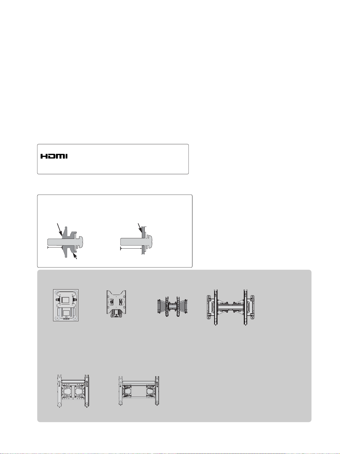
Wall Mounting Bracket(Separate purchase)
(19/22LU50
**
/19/22LU40
**
/19/22LH20
**
/19/22LD3
**
/19/22LG31**)
RW120
(26LG31**/26LU50
**
/32LF25**/32LG2
***
/32LG33
**
/26/32LH20
**
/26/32LD3**/
32LH3
***
/32LH40**/
32LH49**/32LH50
**
/32LH70**/32LF51**)
RW230
(32/37/42LF25
**
/32/37/42LG2
***
/32/37/42LG33
**
/32/37/42LH20
**
/32LD3
**
/32/37/42/47LH3
***
/32/37/42/47LH40
**
/32/37/42/47LH49
**
/32/37/42/47LH50
**
/32/37/42/47LH70
**
/42/47LH90
**
/32/42/47LF51**)
AW-47LG30M
(50PS70**/50PS80
**
/42/50PQ35
**
/42PQ65**/50PS65**)
AW-50PG60MS
(60PS70**/60PS80**)
AW-60PG60MS
12 mm
12 mm
Use screws 12 mm (+ 0.5/- 0.5) long on the SET assembly side.
(
Only 42/47LH70**)
Set assembly side
(without guide spacer)
Set assembly side
(with guide spacer)
Guide spacer
AW-55LH40M
(55LH50**)
HDMI, the HDMI logo and High-Definition
Multimedia Interface are trademarks or registered
trademarks of HDMI Licensing LLC.
1
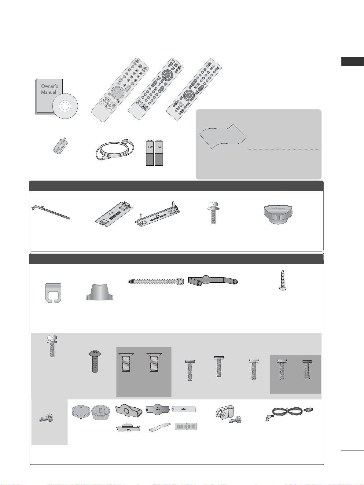
ACCESSORIES
ACCESSORIES
Ensure that the following accessories are included with your TV. If an accessory is missing, please contact
the dealer where you purchased the TV.
■
Image shown may differ from your TV.
Owner’s Manual
Batteries
Remote Control
Power Cord
Polishing Cloth
Polishing cloth for
use on the screen.
This item is not included for all models.
* Lightly wipe any stains or
fingerprints on the surface of the TV with the
polishing cloth.
Do not use excessive force.
This may cause scratching or
discolouration.
or
AV MODE
V MODE
ENERGY
ENERGY SA
SAVING
VING
RETURN / EXIT
MENU
Q.MENU INFO GUIDE
i
M
UTEMUTE
POWERPOWER
LIST
LIST
Q.VIEW
Q.VIEW
MARK
FAV
or
POWER
POWER
TV/RAD
TV/RAD
ON/OFF
ON/OFF
RA RATIO
AV MODEV MODE
MARK
MARK
FAV
Protection cover
(Refer to p.34)
PPLLAASSMMAA TTVV mmooddeellss
LLCCDD TTVV mmooddeellss // LLEEDD LLCCDD TTVV mmooddeellss
Cable management clip
(Only 32/37/42/47LH70**)
(Refer to p.33)
Stand rear cover
(Only 37/42/47LH70**)
(Refer to p.31)
Cable Holder
(Refer to p.33)
Bolts for stand assembly
(Only 50PS70**/50PS80**/
42/50PQ35**/42PQ65**/50PS65**)
(Refer to p.26)
x 4
x 2
Cable management clip
(Only 50/60PS70**,
50/60PS80**)
(Refer to p.33)
(Only 47LH70**)
x 7
Protection Cover
(Except for 19/22LU40**, 19/22/26LU50**)
(Refer to p.34)
or
or
Cable Holder
(Only 19/22LU40**,
19/22/26LU50**)
(Refer to p.32)
Cable management clip
(Only 19/22LH20
*
*,
19/22LD3
*
*,
19/22LG31**)
(Refer to p.32)
(Refer to p.30)
1-screw for stand fixing
(Only 26LG31**, 26LU50**, 32/37/42LF25**,
32/37/42LG2
***
, 32/37/42LG33**,
26/32/37/42LH20**, 26/32LD3**,
32/37/42LH3
***
, 32/37/42LH40**,
32/37/42LH49**, 32/37/42LH50**,
32/37LH70**, 42LH90
**
,
32/42LF51**)
x 8
Bolts for stand assembly
(Refer to p.
25 to28
)
(Only 32LH70**)
M4x20
M4x16
(Only 42LH70**)
x 3
M4x20
M4x16
x 4
(Only
19/22LU50**)
(Only
26LU50**)
x 2 x 3
or
Protective Bracket
and Bolt for Power Cord
(Only 32/37/42/47LH70
*
*
)
(Refer to p.33)
USB extension cable
(Only 32/37/42/47LH70
*
*
)
Make sure to use the provided
USB extension cable, Which is
specially designed for a slim fit.
x 8
M4x20
(Only 37LH70**)
Ferrite Core
(
This item is not included for
all models.
)
x 4
(Only 26LG31**,
32/37/42LF25**,
32/37/42LG2
***
,
32/37/42LG33
**
,
32/42LF51**)
x 4
(Only
19/22LU40**)
x 5
Stand Rear Body
Cap
(Only
19/22LU40**)
(Refer to p.28)
(Only 26LG31**,
32/37/42LF25**,
32/37/42LG2
***
,
32/37/42LG33**,
26/32/37/42LH20**,
26/32LD3**,
32/37/42/47LH3
***
,
32/37/42/47LH40**,
32/37/42/47LH49**,
32/37/42/47LH50**,
42/47LH90
**,
32/42LF51**)
CONTENTS
2
CONTENTS
ACCESSORIES
. . . . . . . . . . . . . . . . . . . . . . . . . . . . . . . . . . . . . . . . . . . .
1
PREPARATION
Front Panel Controls..................................................... 4
Back Panel Information .............................................. 16
Stand Installation ........................................................ 25
Detaching stand .......................................................29
Attaching the TV to a desk .....................................30
Desktop Pedestal Installation............................... 30
Positioning your display ........................................30
Kensington Security System .................................30
Careful installation advice ..................................... 31
Swivel Stand ..................................................................31
To use the stand rear cover ..................................................31
Back Cover for Wire Arrangement.......................... 32
Not Using the desk-type stand ................................34
Wall Mount: Horizontal Installation........................ 35
Antenna Connection.................................................. 36
EXTERNAL EQUIPMENT SETUP
HD Receiver Setup...................................................... 37
DVD Setup .................................................................... 39
VCR Setup..................................................................... 42
Insertion of CI Module .............................................. 44
Digital Audio Out Setup ........................................... 45
Headphone Setup....................................................... 45
Other A/V Source Setup .......................................... 46
Usb Setup...................................................................... 47
PC Setup........................................................................ 48
- Screen Setup for PC Mode................................52
WATCHING TV / PROGRAMME CONTROL
Remote Control Key Functions ............................... 56
Turning on the TV....................................................... 62
Programme Selection ................................................ 62
Volume Adjustment ................................................... 62
Quick Menu ................................................................. 63
On-Screen Menus Selection and Adjustment..... 64
Auto Programme Tuning............................................ 65
Manual Programme Tuning (In Digital Mode)..... 68
Manual Programme Tuning (In Analogue Mode)... 70
Programme Edit ........................................................... 72
Booster(In Digital Mode)...........................................74
Software Update.......................................................... 75
Diagnostics.................................................................... 76
CI Information.............................................................. 77
Selecting the Programme List .................................. 78
Favourite Programme Setup...................................... 79
Input List ....................................................................... 80
Data Service...............................................................81
Input Label .................................................................... 81
Simple Manual.............................................................. 82
................................................................. 83
AV Mode........................................................................ 86
Initializing (Reset to original factory settings) .....87
TO USE A BLUETOOTH
Precautions when using the Bluetooth ................. 88
Setting the Bluetooth ................................................ 89
Set TV PIN .....................................................................90
Bluetooth headset
- Connecting a new Bluetooth headset..............91
- Connecting to Bluetooth headset already
registered.................................................................. 91
-
Disconnecting the Bluetooth headset during use
....92
- When requesting to connect to TV from the
Bluetooth headset....................................................92
Managing Registered Bluetooth device ................ 93
My Bluetooth Information. ........................................94
Receiving Photos from external Bluetooth device.........
95
Listening to the Musics from external Bluetooth device......
95
TO USE A USB DEVICE
When connecting a USB device.............................. 96
Photo List ...................................................................... 97
Music List......................................................................101
Movie List.....................................................................104
DivX Registration Code............................................108
Deactivation.................................................................109

CONTENTS
3
EPG (ELECTRONIC PROGRAMME
GUIDE) (IN DIGITAL MODE)
Switch on/off EPG..................................................... 110
Select a Programme................................................... 110
Button Function in NOW/NEXT Guide Mode...... 110
Button Function in 8 Day Guide Mode.................111
Button Function in Date Change Mode............... 111
Button Function in Extended Description Box .......
112
Button Function in Record/Remind Setting Mode
........ 112
Button Function in Schedule List Mode.............. 112
PICTURE CONTROL
Picture Size (Aspect Ratio) Control ..................... 113
Picture Wizard ..............................................................115
Energy Saving ...............................................................116
Preset Picture Settings
- Picture Mode-Preset .......................................... 117
Manual Picture Adjustment
- Picture Mode-User option................................ 118
Picture Improvement Technology.......................... 119
Expert Picture Control............................................. 120
Picture Reset............................................................... 123
LED Local dimming ..................................................123
Power Indicator............................................................124
Image Sticking Minimization (ISM) Method...... 125
Demo Mode................................................................ 126
Mode Setting ...............................................................127
SOUND & LANGUAGE CONTROL
Auto Volume Leveler................................................. 128
Clear Voice II................................................................129
Preset Sound Settings - Sound Mode .............. 130
Sound Setting Adjustment -User Mode............131
SRS TruSurround XT............................................. 131
Balance .................................................................... 132
TV Speakers On/ Off Setup ................................132
DTV Audio setting (In Digital Mode only) . .133
Selecting Digital Audio Out.................................134
Audio Reset..............................................................135
Audio Description (In Digital Mode only)........136
I/II
- Stereo/Dual Reception (In Analogue Mode Only)
13 7
- NICAM Reception (In Analogue Mode Only) ... 138
- Speaker Sound Output Selection.................. 138
On-Screen Menu Language/Country Selection.... 139
Language Selection (In Digital Mode only)....... 140
TIME SETTING
Clock Setup................................................................. 141
Auto On/ Off Time Setting .................................... 142
Sleep Timer Setting .................................................. 143
PARENTAL CONTROL / RATINGS
Set Password & Lock System................................. 144
Block Programme....................................................... 145
Parental Control (In Digital Mode only)............. 146
External Input Blocking.............................................147
Key Lock ...................................................................... 148
TELETEXT
Switch on/off ............................................................. 149
SIMPLE Text................................................................ 149
TOP Text...................................................................... 149
FASTEXT...................................................................... 150
Special Teletext Functions ...................................... 150
DIGITAL TELETEXT
Teletext within Digital Service................................ 151
Teletext in Digital Service........................................ 151
APPENDIX
Troubleshooting......................................................... 152
Maintenance .............................................................. 154
Product Specifications............................................. 155
IR Codes...................................................................... 169
External Control Device Setup .............................. 170
4
PREPARATION
PREPARATION
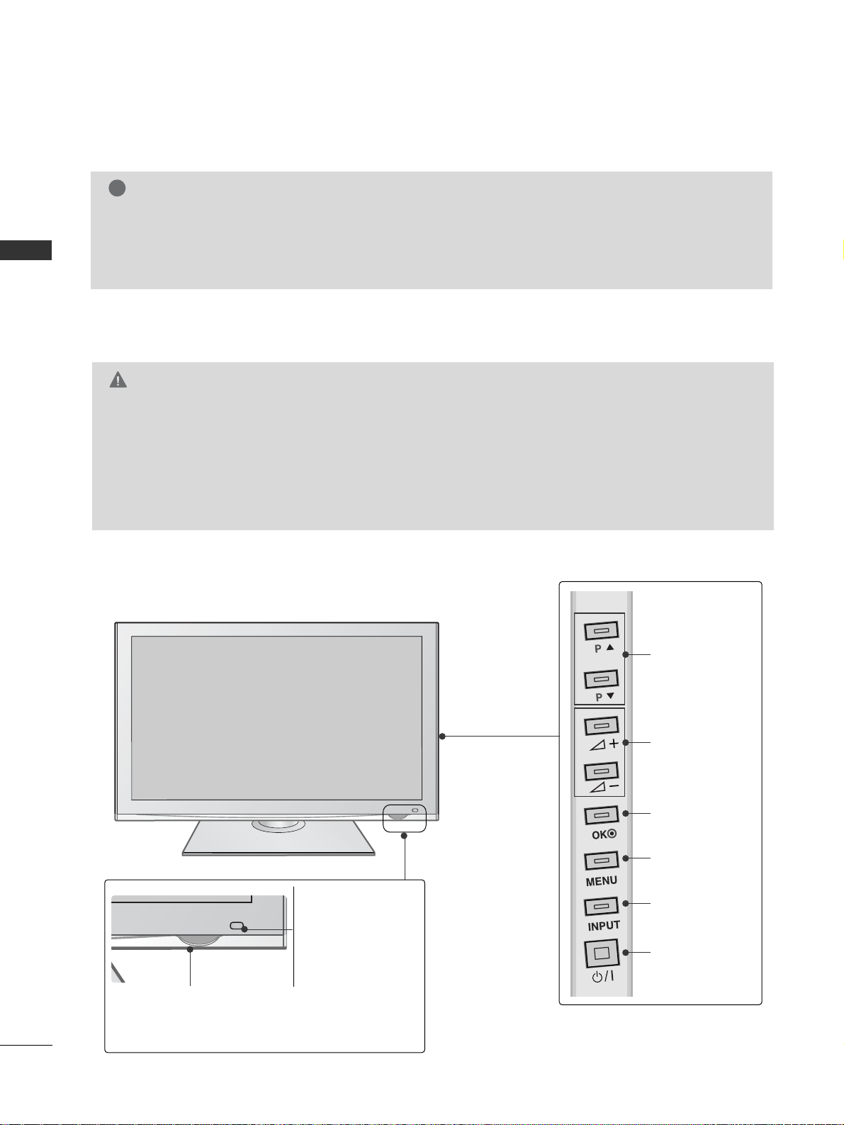
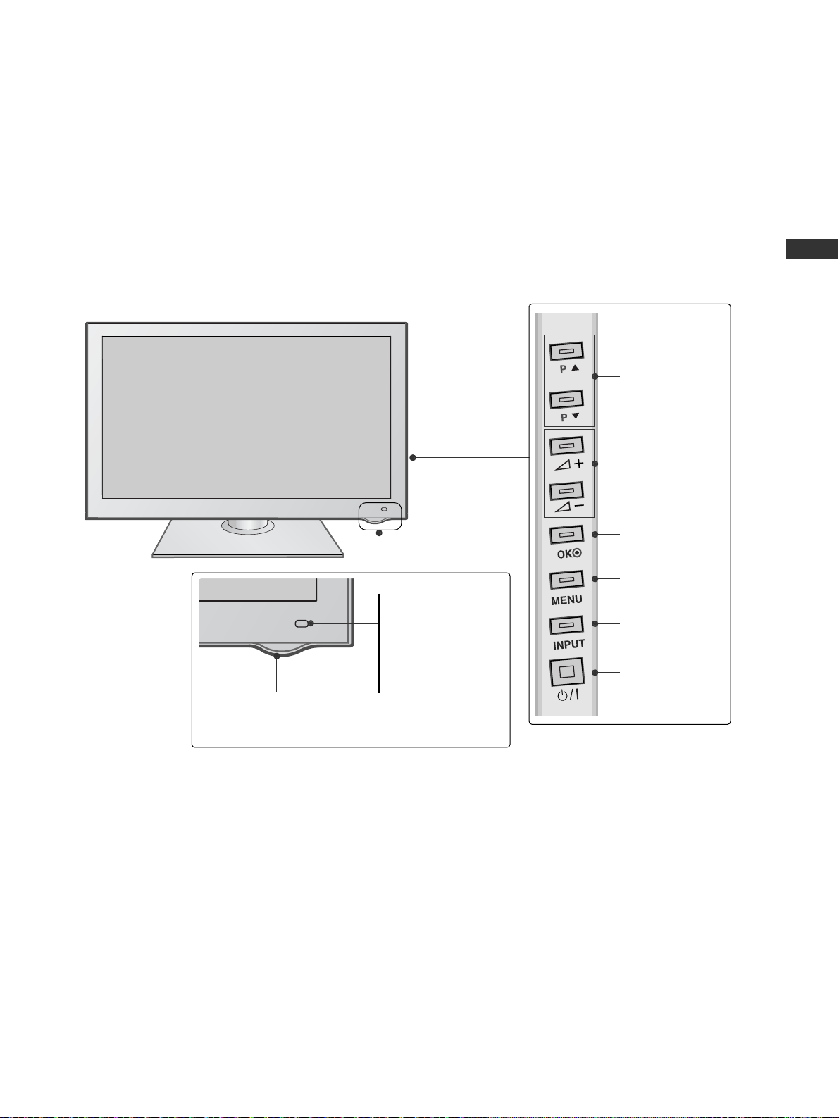
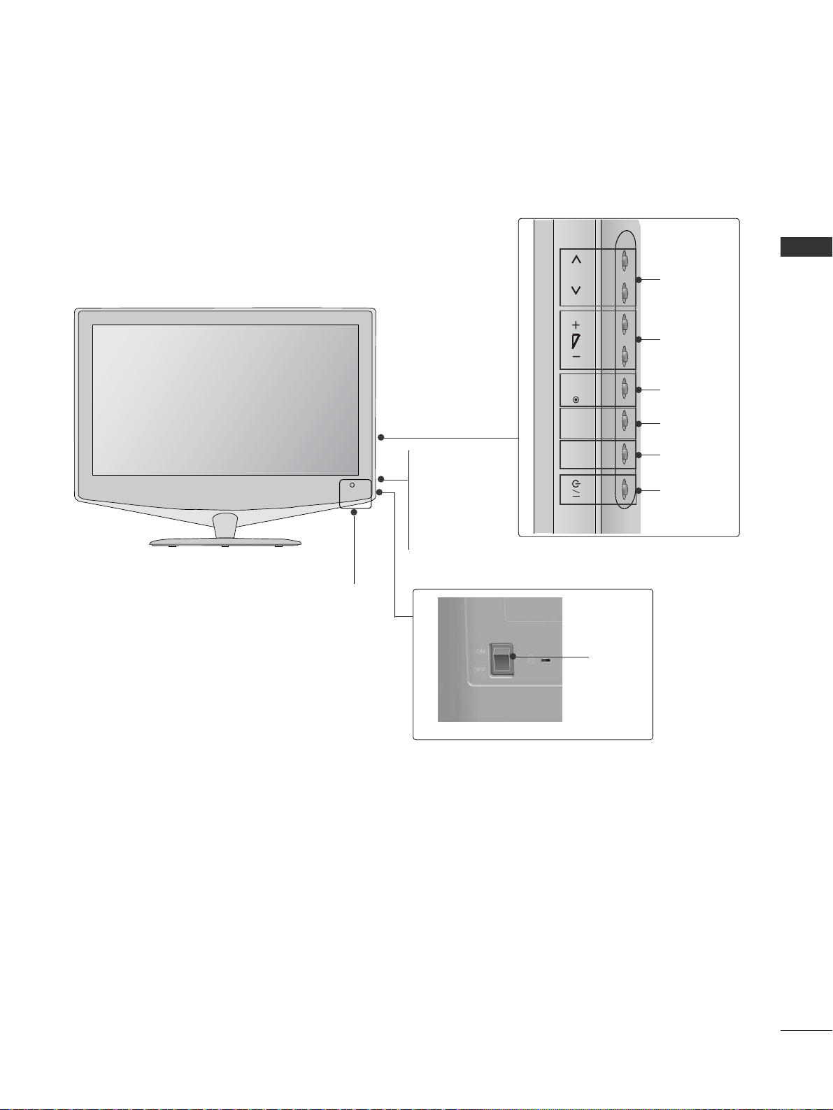
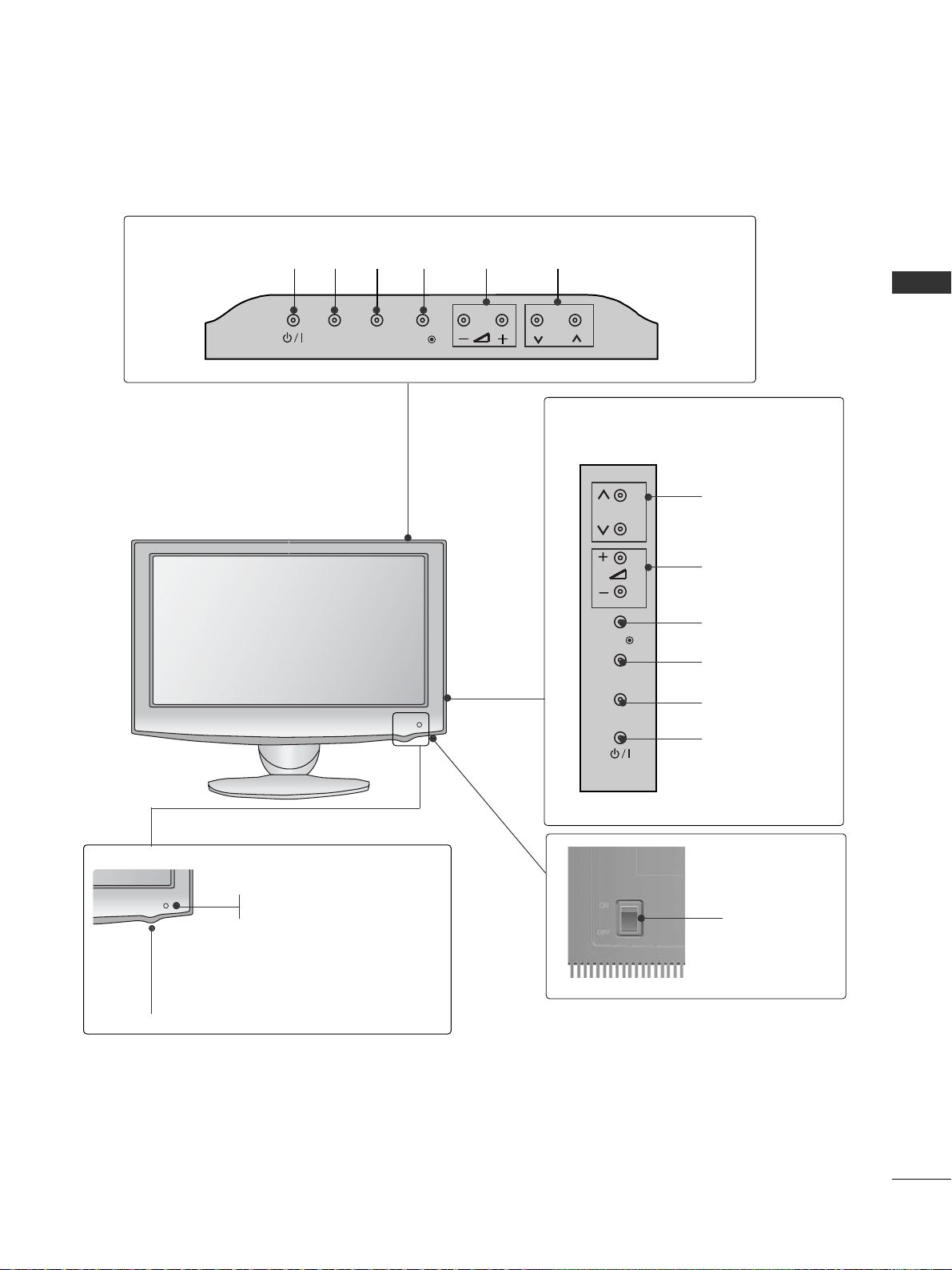
FRONT PANEL CONTROLS
■
Image shown may differ from your TV.
Plasma TV Models
PROGRAMME
VOLUME
OK
MENU
INPUT
POWER
G
When the TV cannot be turned on with the remote control, press the main power button on the TV.
(When the power is turned off with the main power button on the TV, it will not be turned on with the
remote control).
G
Do not step on the glass stand or subject it to any impact.
It may break, causing possible injury from fragments of glass, or the TV may fall.
G
Do not drag the TV. The floor or the product may be damaged.
CAUTION
Power/Standby Indicator
• Illuminates red in standby mode.
•
The LED is off while the TV remains on.
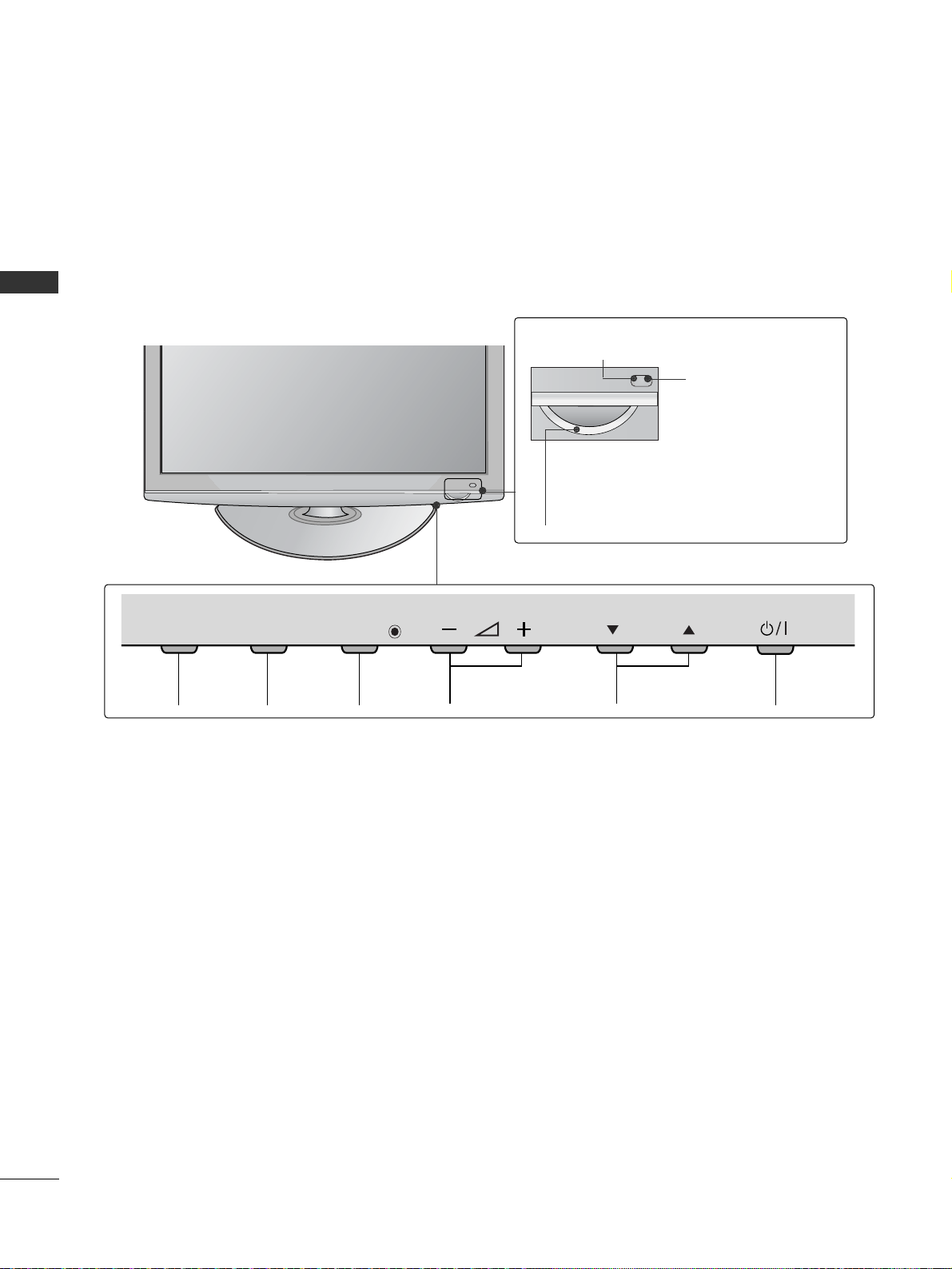
50/60PS70
**
IInn tteellll iiggeenn tt SSeennssoorr
Adjusts picture
according to the surrounding conditions.
RR ee mmoott ee CC oo nnttrrooll
SSeennss oorr
NOTE
!
G
TV can be placed in standby mode in order to reduce the power consumption. And TV should be
switched off using the power switch on the TV if it will not be watched for some time, as this will
reduce energy consumption.
The energy consumed during use can be significantly reduced if the level of brightness of the picture is
reduced, and this will reduce the overall running cost.
5
PREPARATION
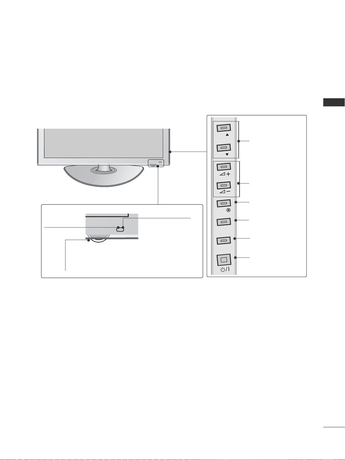
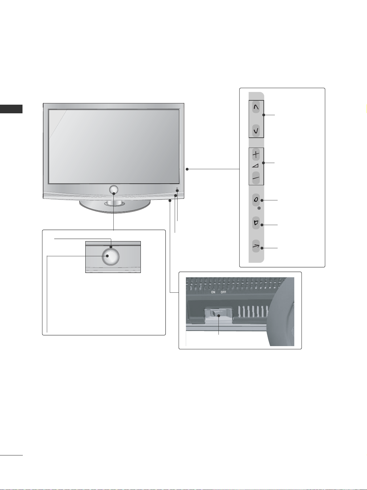
PROGRAMME
VOLUME
OK
MENU
INPUT
POWER
Power/Standby Indicator
• Illuminates red in standby mode.
•
The LED is off while the TV remains on.
50/60PS80
**
IInn tteellll iiggeenn tt SSeennssoorr
Adjusts picture
according to the surrounding conditions.
RR ee mmoott ee CC oo nnttrrooll
SSeennss oorr
6
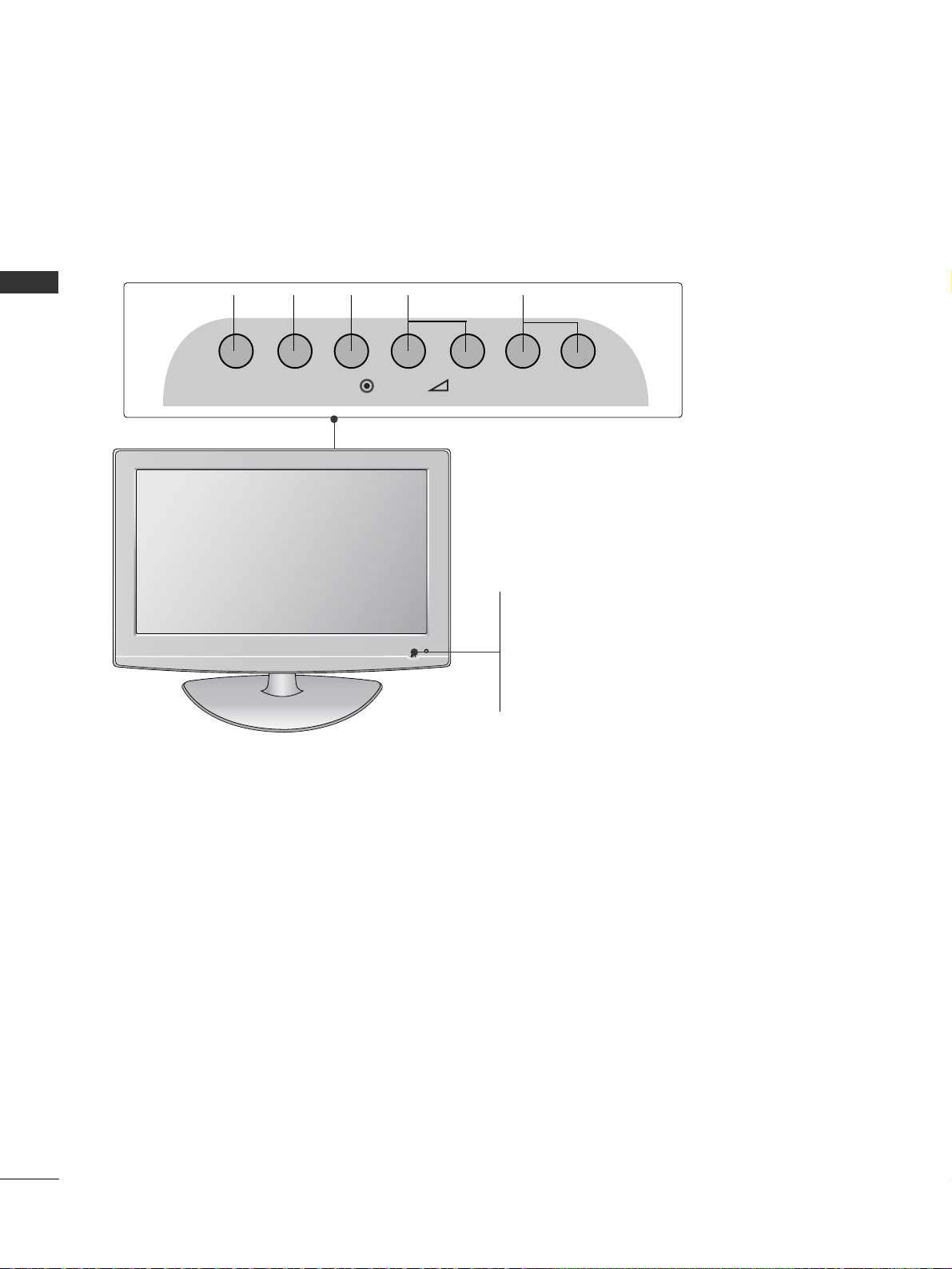
PREPARATION
PREPARATION
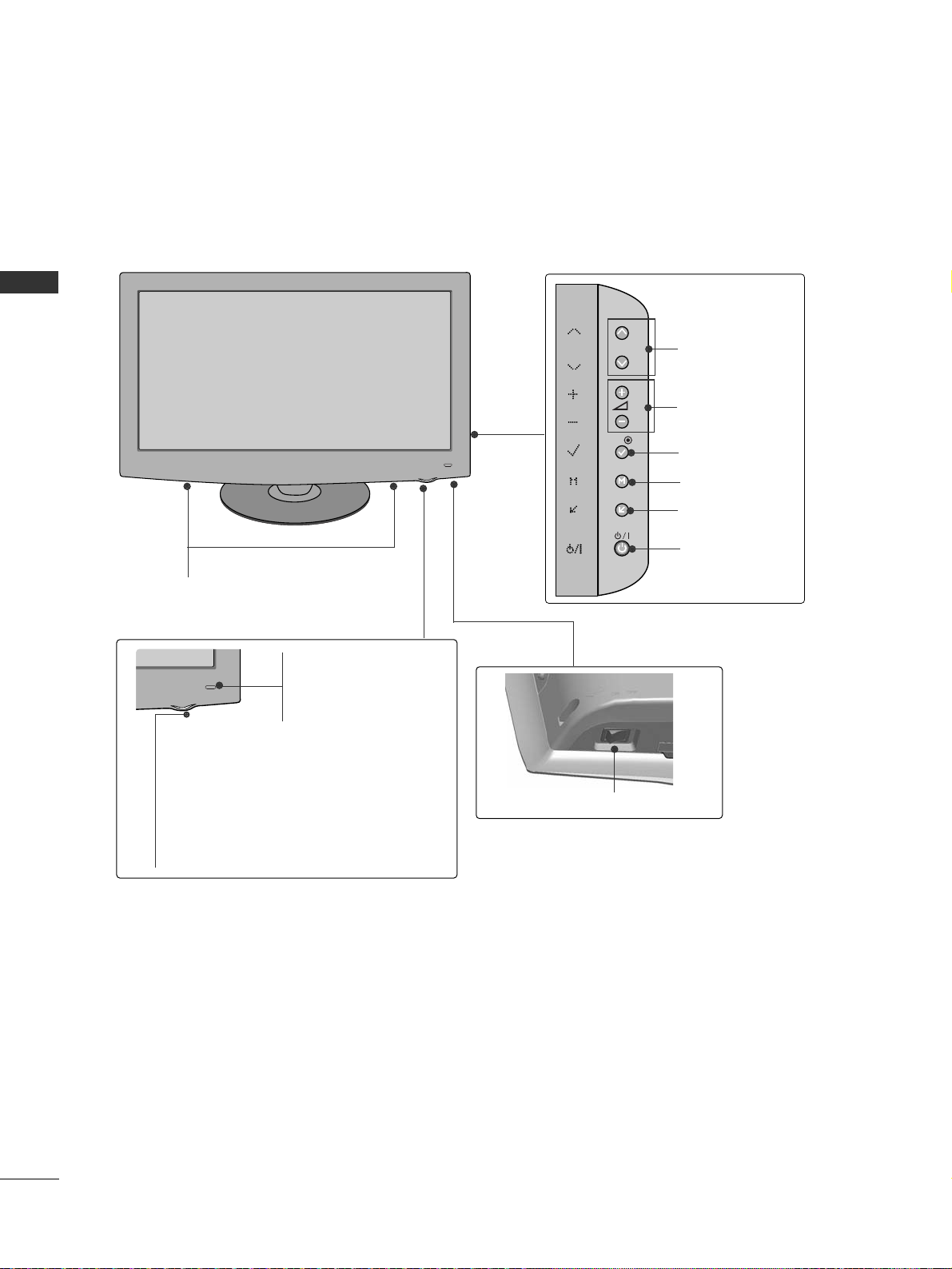
PROGRAMMEVOLUMEMENU OKINPUT POWER
P
MENU
INPUTINPUT
OK
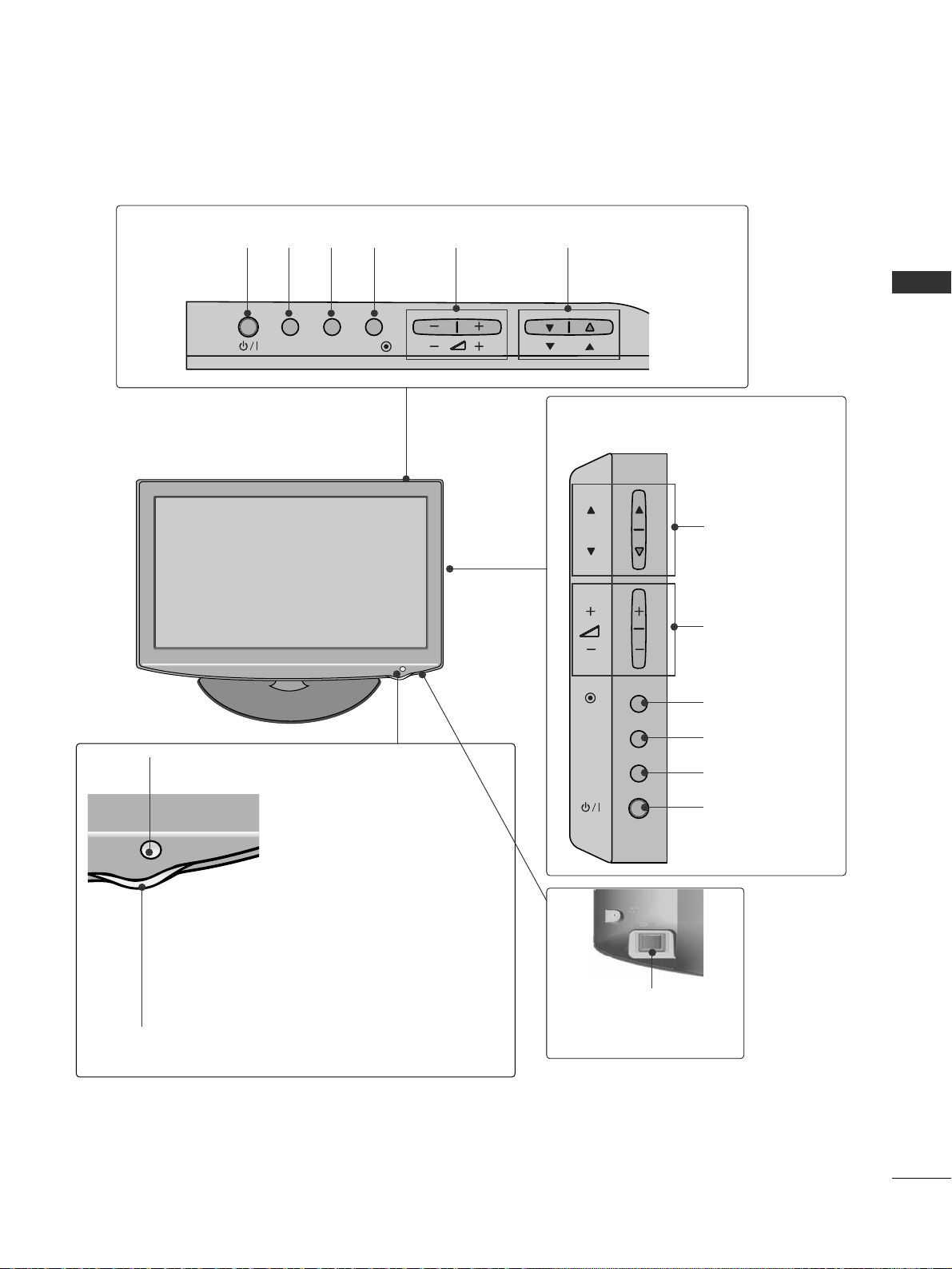
42/50PQ35
**
Intelligent Sensor
Adjusts picture according
to the surrounding
conditions.
Remote Control
Sensor
Power/Standby Indicator
•
Illuminates red in standby mode.
•
Illuminates blue when the TV is switched on.
7
PREPARATION
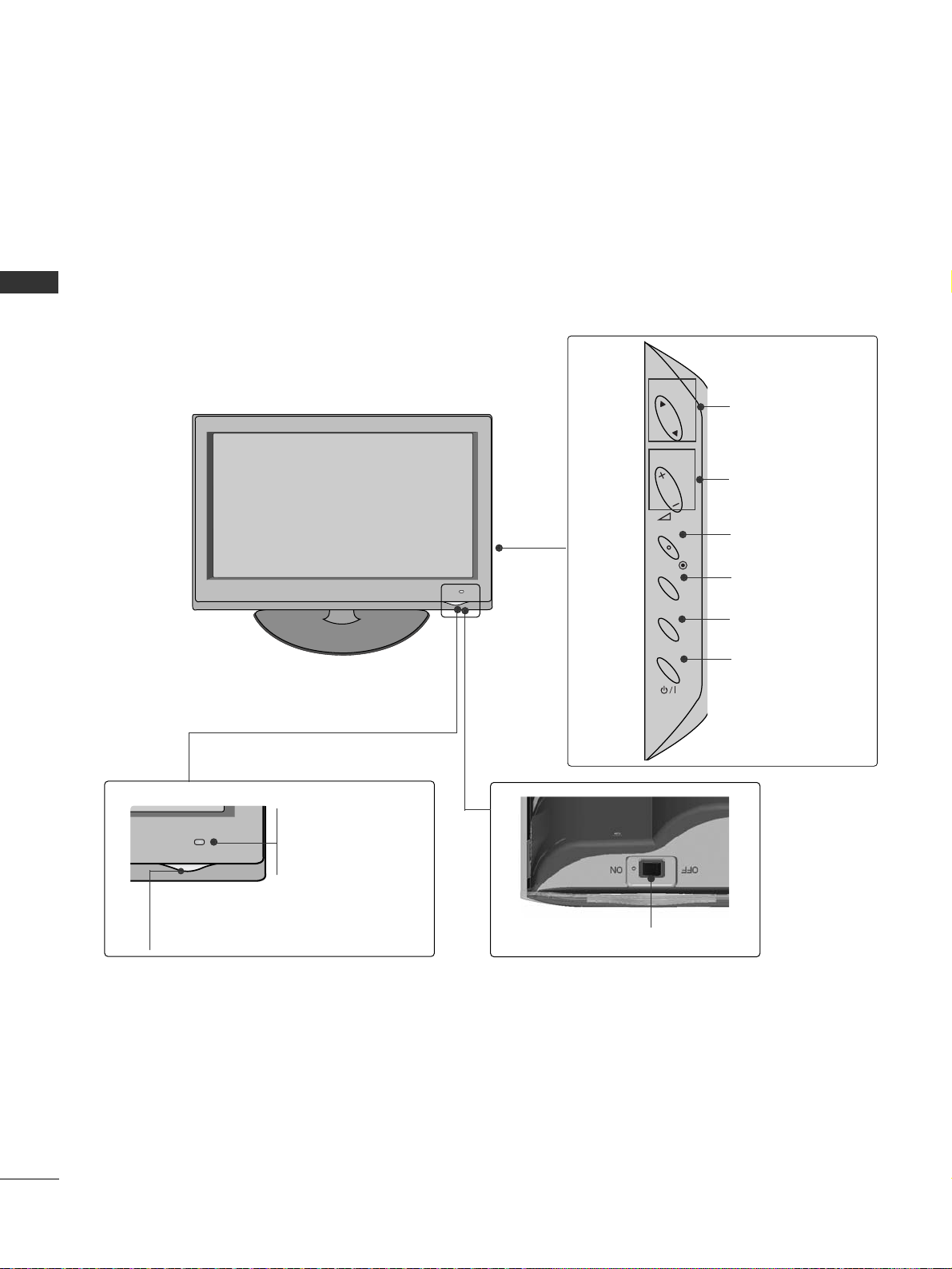
42PQ65**, 50PS65
**
Power/Standby Indicator
• Illuminates red in standby mode.
• The LED is off while the TV remains on.
Remote Control
Sensor
Intelligent Sensor
Adjusts picture according to the surrounding
conditions
MENU
INPUT
OK
P
P
PROGRAMME
VOLUME
OK
MENU
INPUT
POWER
8
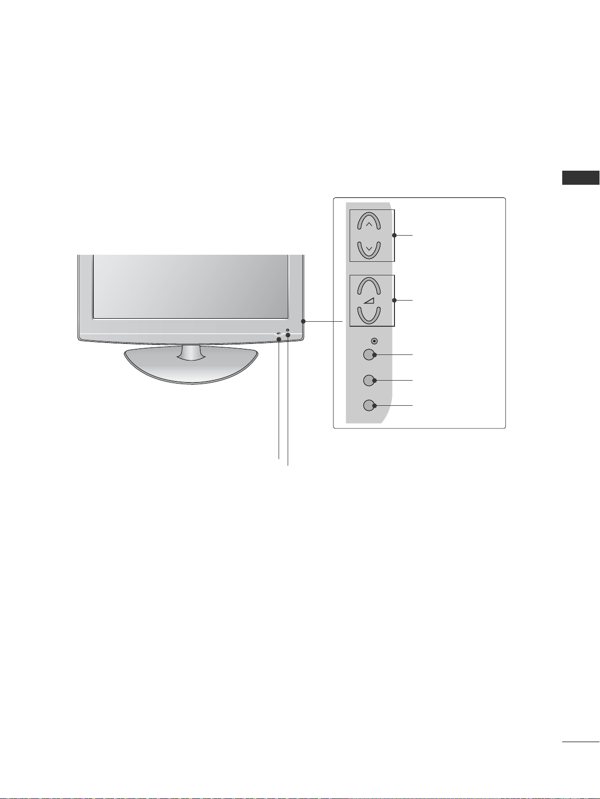
PREPARATION
PREPARATION
INPUT
MENU
OK
P
PROGRAMME
VOLUME
OK
MENU
INPUT
POWER
Remote Control Sensor
Intelligent Sensor
Adjusts picture according to
the surrounding conditions.
Power/Standby Indicator
•
Illuminates red in standby mode.
•
Illuminates white when the TV is switched on.
Note: You can turn the
PPoowweerr II nnddii ccaatt oo rr
on
or off in the OPTION menu.
SPEAKER
LED LCD TV Models : 42/47LH90
**
Main Power Switch
9
PREPARATION
LCD TV Models : 19/22LU40
**
Remote Control Sensor
Main
Power
Switch
INPUT
MENU
OK
P
PROGRAMME
VOLUME
OK
MENU
INPUT
POWER
Power/Standby
Indicator
• illuminates red in
standby mode.
•
The LED is off
while the TV
remains on.
10
PREPARATION
PREPARATION
LCD TV Models : 32/37/42/47LH70
**
P
P
OK
MENU
INPUT
P
PROGRAMME
VOLUME
OK
MENU
INPUT
Intelligent Sensor
Adjusts picture according to
the surrounding conditions
POWER(Touch Sensor)
Power/Standby Indicator
• Illuminates red in standby mode.
• Illuminates whitish when the TV is switched on.
Note: You can adjust
PPoowweerr II nnddii ccaatt oo rr
in the
OPTION menu.
Moving LED
Remote Control Sensor
Main Power Switch
11
PREPARATION
(Only 32/37/42LH20**, 32LD3**,
32/37/42/47LH3
***
)
INPUT MENUPOK
PROGRAMME
VOLUME
(Only 19/22/26LH20**,
19/22/26LD3**)
INPUT
MENU
OK
P
PROGRAMME
VOLUME
OK
MENU
INPUT
POWER
OK
INPUT
POWER
MENU
Main Power Switch
Remote Control Sensor
Power/Standby Indicator
Illuminates red in standby mode.
Illuminates blue when the TV is switched on.
LCD TV Models : 19/22/26/32/37/42LH20**, 19/22/26/32LD3**,
32/37/42/47LH3
***
(This feature is not
available for all models.)
12
PREPARATION
PREPARATION
LCD TV Models : 32/37/42/47LH40**, 32/37/42/47LH49**,
32/37/42/47/55LH50
**
INPUT
MENU
OK
P
PROGRAMME
VOLUME
OK
MENU
INPUT
POWER
Remote Control Sensor
Intelligent Sensor
Adjusts picture according to
the surrounding conditions.
Power/Standby Indicator
• Illuminates red in standby mode.
• Illuminates blue when the TV is switched on.
Main Power Switch
13
PREPARATION
P
INPUT
MENU
OK
P
PROGRAMME
VOLUME
OK
MENU
INPUT
POWER
INPUT
MENU
OK
P
(Only 19/22LU50**)
(Only 26LU50**)
LCD TV Models : 19/22/26LU50
**
VOLUME
POWER
INPUT MENU OK
PROGRAMME
Main
Power
Switch
P
Remote Control Sensor
Power/Standby Indicator
Illuminates red in standby mode.
Illuminates white when the TV is switched on.
14
PREPARATION
PREPARATION
INPUT MENU P-+-+OK
PROGRAMMEVOLUME
MENU
OK
INPUT
LCD TV Models : 19/22LG31
**
POWER
Remote Control Sensor
Power/Standby Indicator
• illuminates red in standby mode.
• illuminates blue when the TV is switched on.
15
PREPARATION
LCD TV Models : 32/37/42LF25
**,
32/37/42LG2
***,
32/37/42LG33
**,
26LG31
**,
32/42/47LF51
**
POWER
Remote Control Sensor
Power/Standby Indicator
• illuminates red in standby mode.
• illuminates blue when the TV is switched on.
P
MENU
INPUT
OK
+
-
PROGRAMME
VOLUME
OK
MENU
INPUT
Intelligent Sensor
Adjusts picture according to the surrounding
conditions. (32/42/47LF51**only)
16
PREPARATION
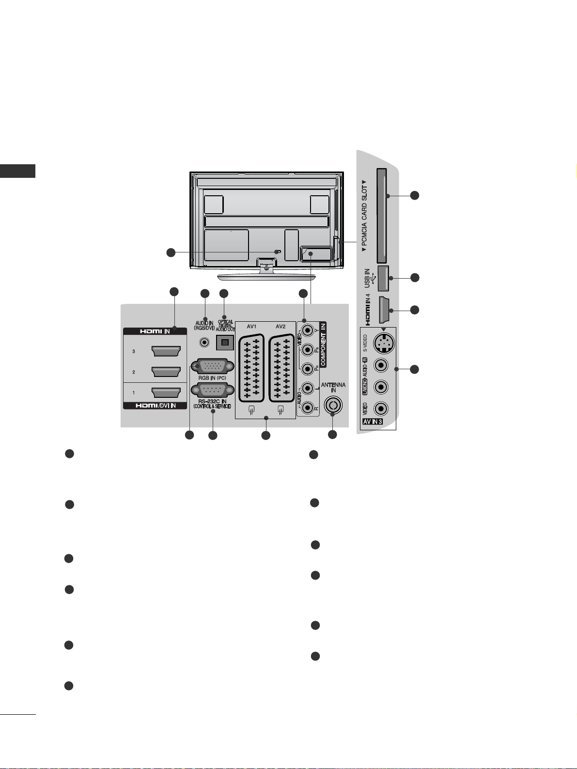
PREPARATION
BACK PANEL INFORMATION
A
Image shown may differ from your TV.
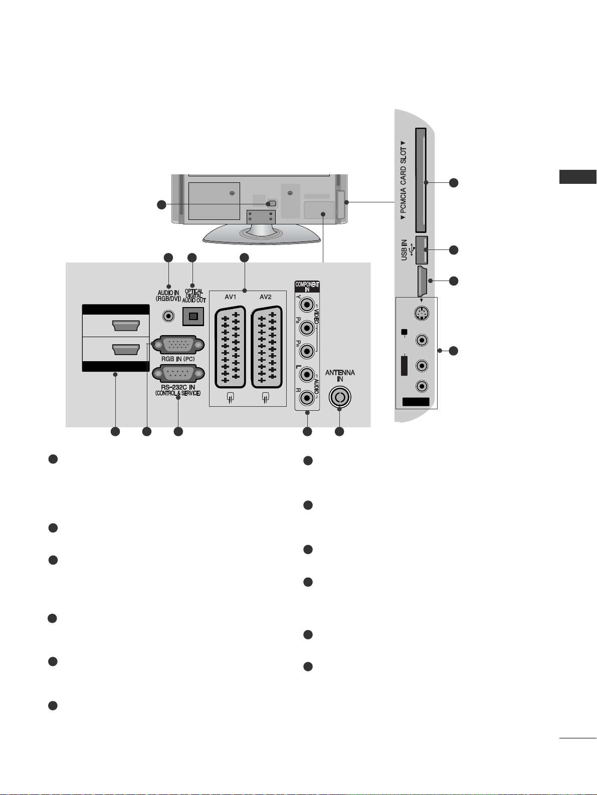
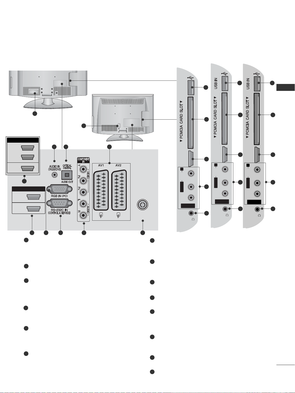
Power Cord Socket
This TV operates on an AC power. The voltage is
indicated on the Specifications page.(
GG
p.155 to
16 7
) Never attempt to operate the TV on DC power.
HDMI/DVI IN Input
Connect an HDMI signal to HDMI IN.
Or DVI(VIDEO)signal to HDMI/DVI port with DVI
to HDMI cable.
RGB/DVI Audio Input
Connect the audio from a PC or DTV.
OPTICAL DIGITAL AUDIO OUT
Connect digital audio to various types of equipment.
Connect to a Digital Audio Component.
Use an Optical audio cable.
Component Input
Connect a component video/audio device to
these jacks.
RGB IN Input
Connect the output from a PC.
RS-232C IN (CONTROL & SERVICE) PORT
Connect to the RS-232C port on a PC.
This port is used for Service or Hotel mode.
Euro Scart Socket (AV1/AV2)
Connect scart socket input or output from an
external device to these jacks.
Antenna Input
Connect antenna or cable to this jack.
PCMCIA (Personal Computer Memory Card
International Association) Card Slot
Insert the CI Module to
PPCCMMCCIIAA CCAA RR DD SSLL OOTT..
(This feature is not available in all countries.)
USB Input
Connect USB storage device to this jack.
S-Video Input
Connect S-Video out from an S-VIDEO device.
Audio/Video Input
Connect audio/video output from an external
device to these jacks.
1
2
3
4
7
8
9
10
11
12
1
5
6
2
3 4 5
6
7 8
9
Plasma TV Models : 50/60PS70**, 50/60PS80**
10
11
2
12
17
PREPARATION
Power Cord Socket
This TV operates on an AC power. The voltage is
indicated on the Specifications page. (
GG
p.155 to
16 7
) Never attempt to operate the TV on DC
power.
RGB/DVI Audio Input
Connect the audio from a PC or DTV.
OPTICAL DIGITAL AUDIO OUT
Connect digital audio to various types of equipment.
Connect to a Digital Audio Component.
Use an Optical audio cable.
Euro Scart Socket (AV1/AV2)
Connect scart socket input or output from an
external device to these jacks.
HDMI/DVI IN Input
Connect an HDMI signal to HDMI IN. Or DVI (VIDEO)
signal to HDMI/DVI port with DVI to HDMI cable.
RGB IN Input
Connect the output from a PC.
RS-232C IN (CONTROL & SERVICE) PORT
Connect to the RS-232C port on a PC.
This port is used for Service or Hotel mode.
Component Input
Connect a component video/audio device to
these jacks.
Antenna Input
Connect RF antenna to this jack.
PCMCIA (Personal Computer Memory Card
International Association) Card Slot
Insert the CI Module to
PPCCMMCCIIAA CCAA RR DD SSLLOOTT..
(This feature is not available in all countries.)
USB Input
Connect USB storage device to this jack.
S-Video Input
Connect S-Video out from an S-VIDEO device.
Audio/Video Input
Connect audio/video output from an external
device to these jacks.
1
2
3
4
5
6
7
8
9
10
11
12
R
1
HDMI IN
HDMI/DVI IN
2
1
AV IN 3
L/ MONO
R
AUDIO
VIDEO
S-VIDEO HDMI IN 3
AV IN 3
L/MONO
R
AUDIOAUDIO
VIDEOVIDEO
S-VIDEO HDMI IN 3
USB IN
SERVICE ONLY
10
11
5
243
95 6 7 8
12
Plasma TV Models : 42/50PQ35
**,
42PQ65
**,
50PS65
**
18
PREPARATION
PREPARATION
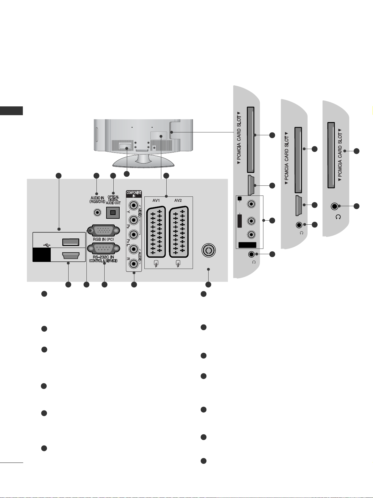
LCD TV Models : 32/37/42LF25**, 32/37/42LG2
***
, 32/37/42LG33**,
19/22/26LG31
**
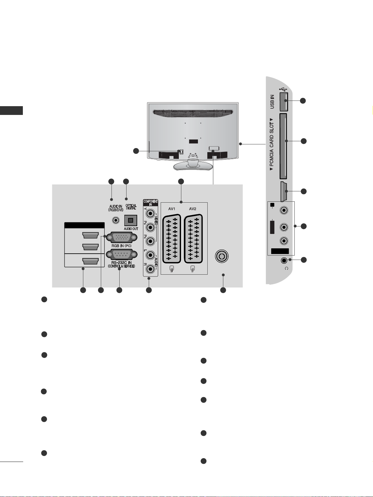
Power Cord Socket
This TV operates on an AC power. The voltage is
indicated on the Specifications page.(
GG
p.155 to
16 7
) Never attempt to operate the TV on DC power.
RGB/DVI Audio Input
Connect the audio from a PC or DTV.
OPTICAL DIGITAL AUDIO OUT
Connect digital audio to various types of equipment.
Connect to a Digital Audio Component.
Use an Optical audio cable.
Euro Scart Socket (AV1/AV2)
Connect scart socket input or output from an
external device to these jacks.
HDMI/DVI IN Input
Connect an HDMI signal to HDMI IN. Or DVI
(VIDEO) signal to HDMI/DVI port with DVI to HDMI
cable.
RGB IN Input
Connect the output from a PC.
RS-232C IN (CONTROL & SERVICE) PORT
Connect to the RS-232C port on a PC.
This port is used for Service or Hotel mode.
Component Input
Connect a component video/audio device to
these jacks.
Antenna Input
Connect antenna or cable to this jack.
PCMCIA (Personal Computer Memory Card
International Association) Card Slot
Insert the CI Module to
PPCCMMCCIIAA CCAA RR DD SSLLOOTT..
(This feature is not available in all countries.)
Audio/Video Input
Connect audio/video output from an external
device to these jacks.
Headphone Socket
Plug the headphone into the headphone socket.
SERVICE ONLY PORT
1
2
3
4
5
6
7
8
9
10
11
12
13
AV IN 3
L/MONO
R
AUDIOAUDIO
VIDEOVIDEO
HDMI
IN 2
H/P
10
5
11
12
AV IN 3
L/ MONO
R
AUDIO
VIDEO
HDMI
IN 2
1
ANTENNA IN
H/P
USB IN
SERVICE ONLY
HDMI
/ DVI IN
(RGB)
2
13
4
3
95 6 7 8
(Only 32/37/42LG2
***
,
32/37/42LG33**,
26LG 31**)
HDMI
IN 2
H/P
10
5
12
(Only 32/37/42LF25**)
1
H/P
12
10
(Only 19/22LG31**)
19
PREPARATION
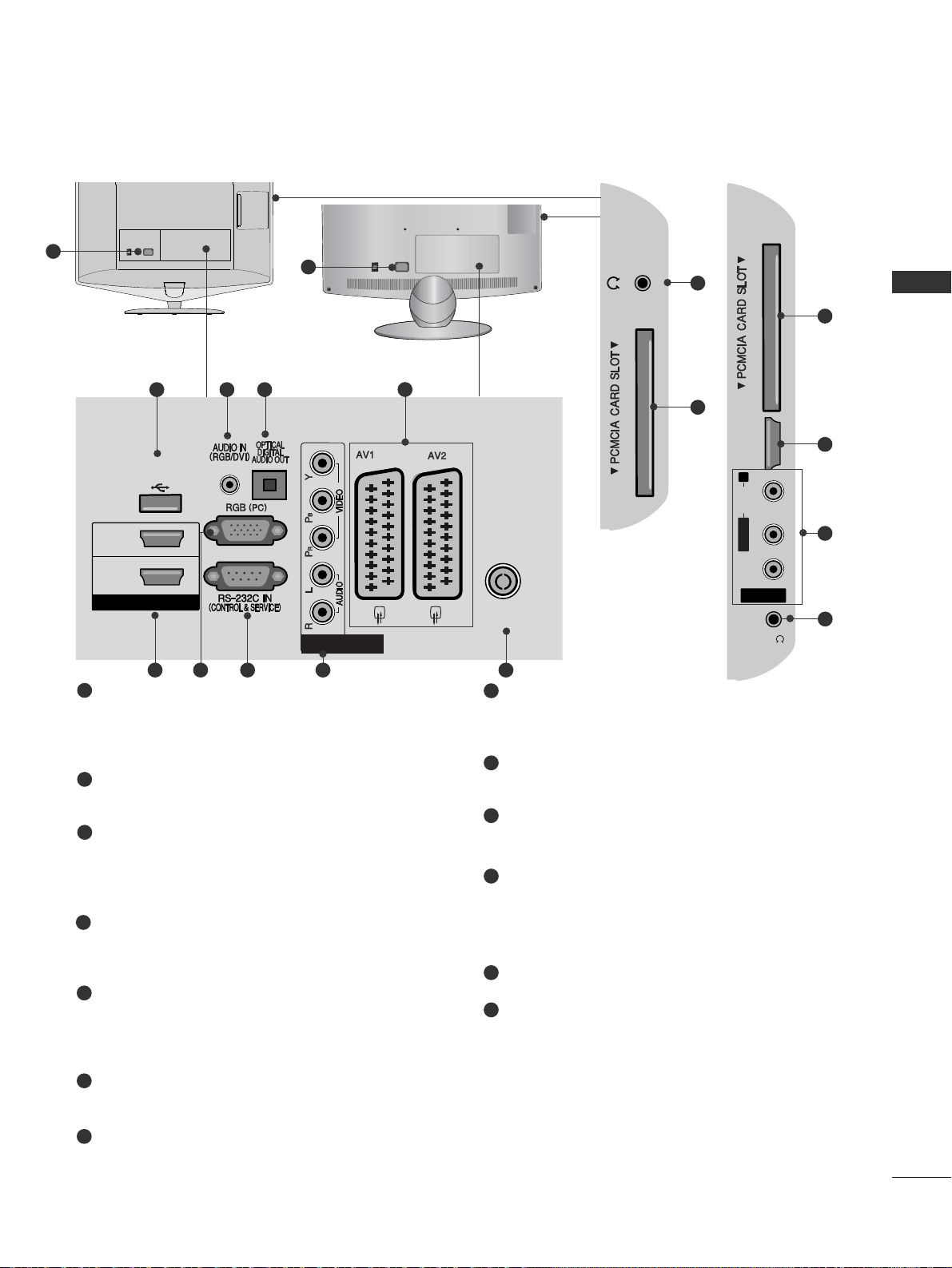
LCD TV Models : 19/22LU40**, 19/22/26LU50
**
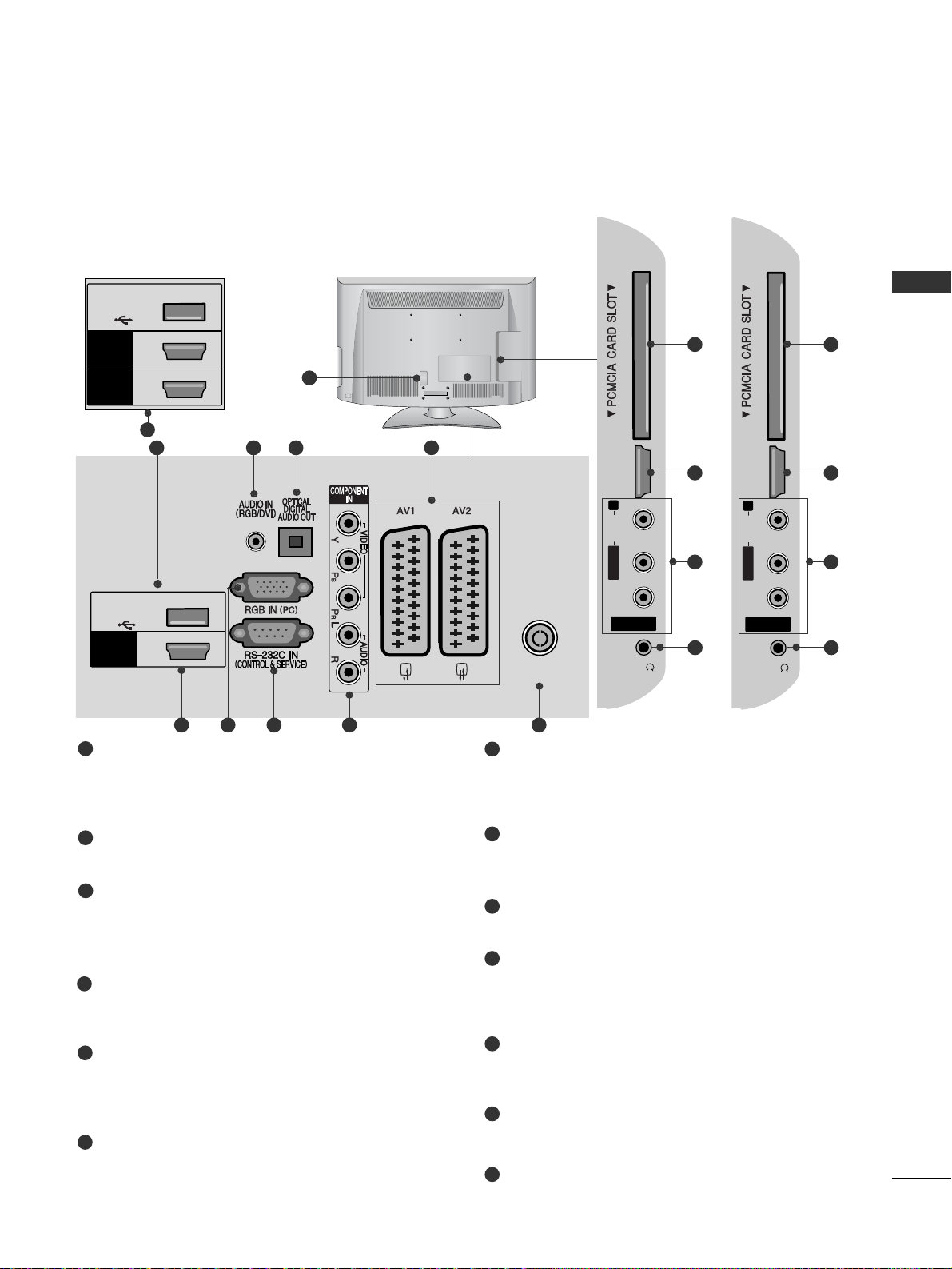
Power Cord Socket
This TV operates on an AC power. The voltage is
indicated on the Specifications page.(
GG
p.155 to
16 7
) Never attempt to operate the TV on DC power.
RGB/DVI Audio Input
Connect the audio from a PC or DTV.
OPTICAL DIGITAL AUDIO OUT
Connect digital audio to various types of equipment.
Connect to a Digital Audio Component.
Use an Optical audio cable.
Euro Scart Socket (AV1/AV2)
Connect scart socket input or output from an
external device to these jacks.
HDMI/DVI IN Input
Connect an HDMI signal to HDMI IN. Or DVI
(VIDEO) signal to HDMI/DVI port with DVI to HDMI
cable.
RGB Input
Connect the output from a PC.
RS-232C IN (CONTROL & SERVICE) PORT
Connect to the RS-232C port on a PC.
This port is used for Service or Hotel mode.
Component Input
Connect a component video/audio device to
these jacks.
Antenna Input
Connect antenna or cable to this jack.
Headphone Socket
Plug the headphone into the headphone socket.
PCMCIA (Personal Computer Memory Card
International Association) Card Slot
Insert the CI Module to
PPCCMMCCIIAA CCAA RR DD SSLLOOTT..
(This feature is not available in all countries.)
SERVICE ONLY PORT
Audio/Video Input
Connect audio/video output from an external
device to these jacks.
1
2
3
4
5
6
7
8
9
10
11
12
13
H/P
R
AUDIO
HDMI
IN 3
11
10
H/P
AV IN 3
L/MONO
R
AUDIO
VIDEO
HDMI
IN 3
H/P
ON
OFF
1
ON
OFF
1
HDMI / DVI IN
2
1(DVI)
ANTENNA IN
COMPONENT IN
USB IN
SERVICE ONLY
H/P
AV IN 3
L/ MONO
R
AUDIO
VIDEO
HDMI
IN 3
H/P
(RGB)
ON
OFF
2
12
4
3
95 6 7 8
AV IN 3
L/MONO
R
AUDIOAUDIO
VIDEOVIDEO
HDMI
IN 3
H/P
11
5
13
10
(Only 26LU50**)
(Only 19/22LU40**)
(Only 19/22/26LU50**)
20
PREPARATION
PREPARATION
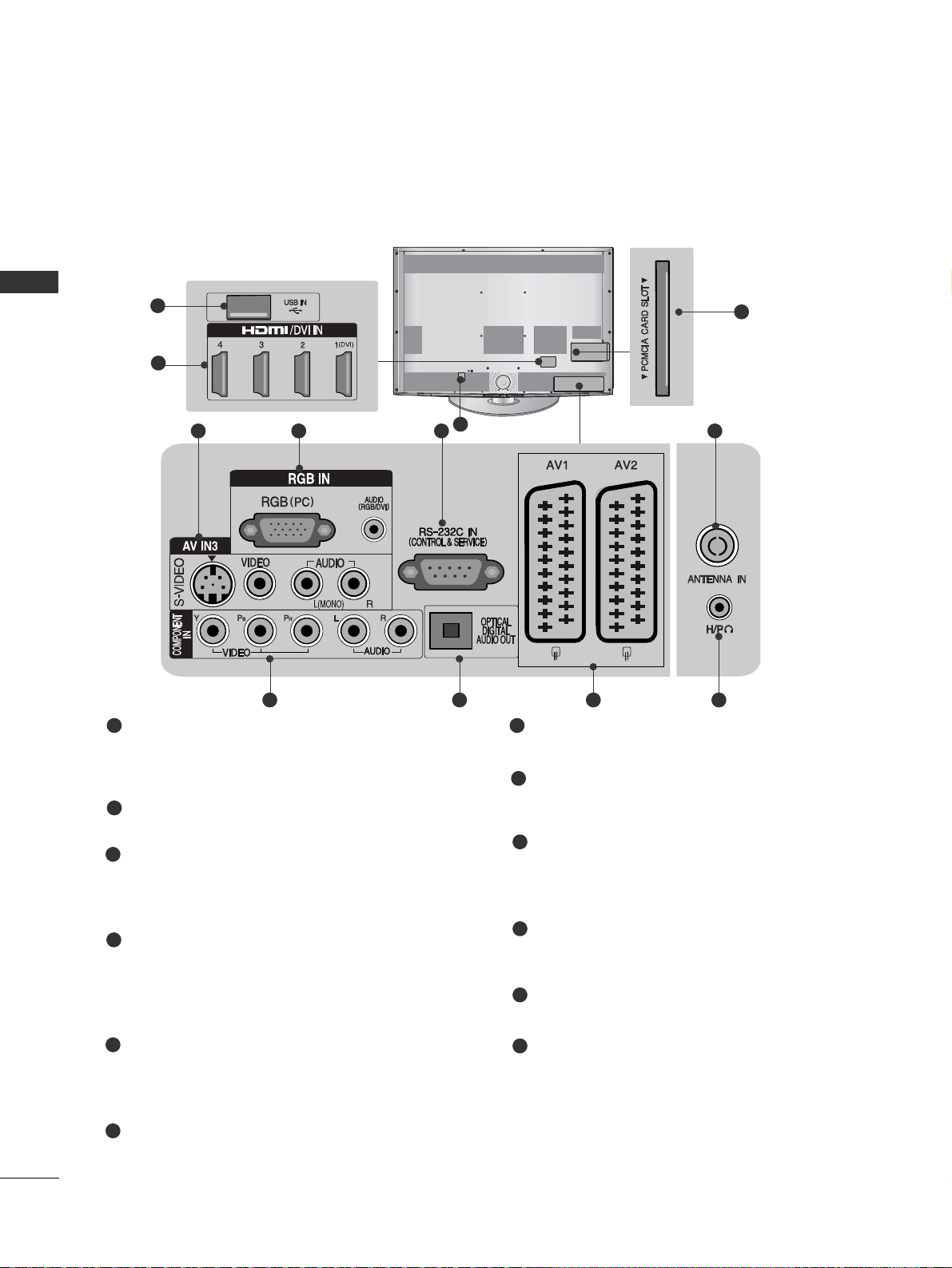
LCD TV Models : 32/37/42/47LH70
**
Power Cord Socket
This TV operates on an AC power. The voltage is
indicated on the Specifications page.(
GG
p.155 to
16 7
) Never attempt to operate the TV on DC power.
USB Input
Connect USB storage device to this jack.
HDMI/DVI IN Input
Connect an HDMI signal to HDMI IN.
Or DVI(VIDEO)signal to HDMI/DVI port with DVI
to HDMI cable.
S-Video Input
Connect S-Video out from an S-VIDEO device.
Audio/Video Input
Connect audio/video output from an external
device to these jacks.
RGB IN Input
Connect the output from a PC.
RGB/DVI Audio Input
Connect the audio from a PC or DTV.
RS-232C IN (CONTROL & SERVICE) PORT
Connect to the RS-232C port on a PC.
This port is used for Service or Hotel mode.
Antenna Input
Connect antenna or cable to this jack.
Component Input
Connect a component video/audio device to
these jacks.
OPTICAL DIGITAL AUDIO OUT
Connect digital audio to various types of equipment.
Connect to a Digital Audio Component.
Use an Optical audio cable.
Euro Scart Socket (AV1/AV2)
Connect scart socket input or output from an
external device to these jacks.
Headphone Socket
Plug the headphone into the headphone socket.
PCMCIA (Personal Computer Memory Card
International Association) Card Slot
Insert the CI Module to
PPCCMMCCIIAA CCAA RR DD SSLL OOTT..
(This feature is not available in all countries.)
1
2
3
4
7
8
9
10
11
12
5
6
(RGB)
1
5 764
10 118 9
12
2
3
21
PREPARATION
LCD TV Models : 32/37/42/47LH40**, 32/37/42/47LH49**,
32/37/42/47/
55LH50
**
,
32/42/47LF51
**
Power Cord Socket
This TV operates on an AC power. The voltage is
indicated on the Specifications page.(
GG
p.155 to
16 7
) Never attempt to operate the TV on DC power.
RGB/DVI Audio Input
Connect the audio from a PC or DTV.
OPTICAL DIGITAL AUDIO OUT
Connect digital audio to various types of equipment.
Connect to a Digital Audio Component.
Use an Optical audio cable.
Euro Scart Socket (AV1/AV2)
Connect scart socket input or output from an
external device to these jacks.
HDMI/DVI IN Input
Connect an HDMI signal to HDMI IN. Or DVI
(VIDEO) signal to HDMI/DVI port with DVI to HDMI
cable.
RGB IN Input
Connect the output from a PC.
RS-232C IN (CONTROL & SERVICE) PORT
Connect to the RS-232C port on a PC.
This port is used for Service or Hotel mode.
Component Input
Connect a component video/audio device to
these jacks.
Antenna Input
Connect antenna or cable to this jack.
USB Input
Connect USB storage device to this jack.
PCMCIA (Personal Computer Memory Card
International Association) Card Slot
Insert the CI Module to
PPCCMMCCIIAA CCAA RR DD SSLLOOTT..
(This feature is not available in all countries.)
Audio/Video Input
Connect audio/video output from an external
device to these jacks.
Headphone Socket
Plug the headphone into the headphone socket.
SERVICE ONLY PORT
1
2
3
4
5
6
8
7
9
10
11
12
13
14
AV IN 3AV IN 3
L/L/MONOMONO
R
AUDIOAUDIO
VIDEOVIDEO
HDMI HDMI
IN 3IN 3
H/PH/P
AV IN 3
L/MONO
R
AUDIO
VIDEO
HDMI
IN 3
H/P
11
10
5
12
13
AV IN 3AV IN 3
L/L/MONOMONO
R
AUDIOAUDIO
VIDEOVIDEO
HDMI HDMI
IN 3IN 3
H/PH/P
USB IN
SERVICE ONLY
11
14
5
12
13
AV IN 3
L/MONO
R
AUDIOAUDIO
VIDEOVIDEO
HDMI
IN 4
H/P
11
10
5
12
13
1
AV IN 3
L/MONO
R
AUDIO
VIDEO
HDMI
IN 3
HDMI / DVI IN
2
1(DVI)
ANTENNA IN
H/P
AV IN 3
L/MONO
R
AUDIO
VIDEO
HDMI
IN 3
H/P
(RGB)
243
95 6 7 8
HDMI / DVI IN
2
3
1(DVI)
AV IN 3
L/ MONO
R
AUDIO
VIDEO
HDMI
IN 4
H/P
(Only 32/37/42/47/55LH50**,
32/37/42/47LH49**)
5
(Only 32/37/42/47/55LH50**,
32/37/42/47LH49**)
1
(Only 32/42/47LF51**)
(Only 32/42/47LF51**)
(Only
32/37/42/47LH40**)
22
PREPARATION
PREPARATION
LED LCD TV Models : 42/47LH90
**
Power Cord Socket
This TV operates on an AC power. The voltage is
indicated on the Specifications page.(
GG
p.155 to
16 7
) Never attempt to operate the TV on DC power.
RGB/DVI Audio Input
Connect the audio from a PC or DTV.
OPTICAL DIGITAL AUDIO OUT
Connect digital audio to various types of equipment.
Connect to a Digital Audio Component.
Use an Optical audio cable.
Euro Scart Socket (AV1/AV2)
Connect scart socket input or output from an
external device to these jacks.
HDMI/DVI IN Input
Connect an HDMI signal to HDMI IN. Or DVI
(VIDEO) signal to HDMI/DVI port with DVI to HDMI
cable.
RGB IN Input
Connect the output from a PC.
RS-232C IN (CONTROL & SERVICE) PORT
Connect to the RS-232C port on a PC.
This port is used for Service or Hotel mode.
Component Input
Connect a component video/audio device to
these jacks.
Antenna Input
Connect antenna or cable to this jack.
USB Input
Connect USB storage device to this jack.
PCMCIA (Personal Computer Memory Card
International Association) Card Slot
Insert the CI Module to
PPCCMMCCIIAA CCAA RR DD SSLLOOTT..
(This feature is not available in all countries.)
Audio/Video Input
Connect audio/video output from an external
device to these jacks.
Headphone Socket
Plug the headphone into the headphone socket.
1
2
3
4
5
6
8
7
9
10
11
12
13
AV IN 3
L/MONO
R
AUDIOAUDIO
VIDEOVIDEO
HDMI
IN 4
H/P
11
10
5
12
13
1
HDMI / DVI IN
2
3
1(DVI)
ANTENNA IN
AV IN 3
L/ MONO
R
AUDIO
VIDEO
HDMI
IN 4
H/P
(RGB)
243
95 6 7 8
23
PREPARATION
LCD TV Models : 26/32/37/42LH20**, 26/32LD3**, 32/37/42/47LH3
***
Power Cord Socket
This TV operates on an AC power. The voltage is
indicated on the Specifications page.(
GG
p.155 to
16 7
) Never attempt to operate the TV on DC power.
RGB/DVI Audio Input
Connect the audio from a PC or DTV.
OPTICAL DIGITAL AUDIO OUT
Connect digital audio to various types of equipment.
Connect to a Digital Audio Component.
Use an Optical audio cable.
Euro Scart Socket (AV1/AV2)
Connect scart socket input or output from an
external device to these jacks.
HDMI/DVI IN Input
Connect an HDMI signal to HDMI IN. Or DVI
(VIDEO) signal to HDMI/DVI port with DVI to HDMI
cable.
RGB IN Input
Connect the output from a PC.
RS-232C IN (CONTROL & SERVICE) PORT
Connect to the RS-232C port on a PC.
This port is used for Service or Hotel mode.
Component Input
Connect a component video/audio device to
these jacks.
Antenna Input
Connect antenna or cable to this jack.
PCMCIA (Personal Computer Memory Card
International Association) Card Slot
Insert the CI Module to
PPCCMMCCIIAA CCAA RR DD SSLLOOTT..
(This feature is not available in all countries.)
Audio/Video Input
Connect audio/video output from an external
device to these jacks.
Headphone Socket
Plug the headphone into the headphone socket.
SERVICE ONLY PORT
1
2
3
4
5
6
7
8
9
10
11
12
13
AV IN 3
L/MONO
R
AUDIOAUDIO
VIDEOVIDEO
HDMI
IN 3
H/P
10
5
11
12
AV IN 3
L/MONO
R
AUDIOAUDIO
VIDEOVIDEO
HDMI
IN 2
H/P
10
5
11
12
1
AV IN 3
L/ MONO
R
AUDIO
VIDEO
HDMI
IN 2
1
ANTENNA IN
H/P
USB IN
SERVICE ONLY
HDMI
/ DVI IN
(RGB)
2
13
4
3
95 6 7 8
AV IN 3
L/ MONO
R
AUDIO
VIDEO
HDMI
IN 3
2
1
H/P
USB IN
SERVICE ONLY
HDMI
/ DVI IN
HDMI
(Only 32/37/42/47LH3
***
)
5
(Only 32/37/42/47LH3
***
)
(Only 26/32/37/42LH20**,
26/32LD3**)
24
PREPARATION
PREPARATION
LCD TV Models : 19/22LH20**, 19/22LD3
**
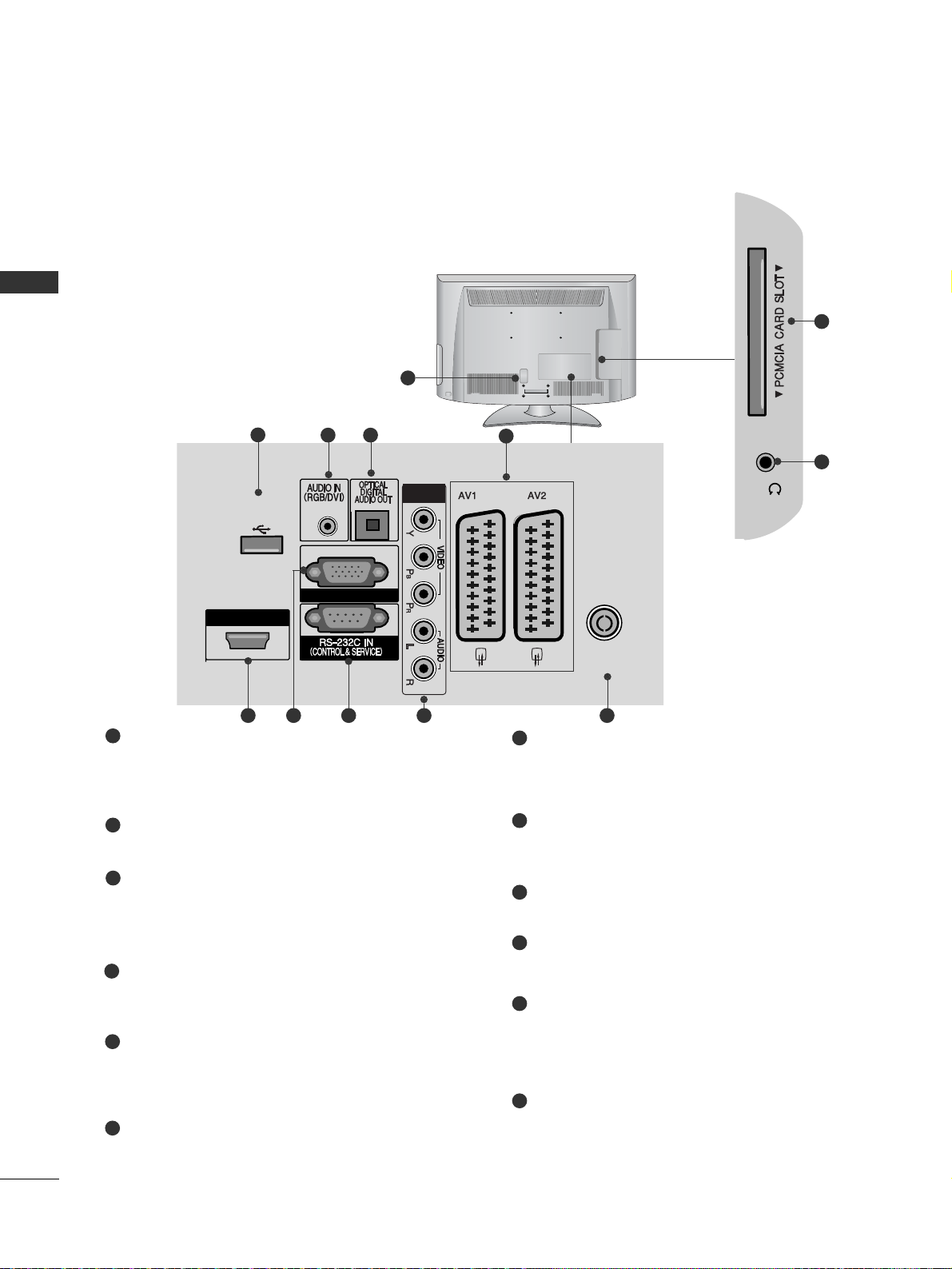
Power Cord Socket
This TV operates on an AC power. The voltage is
indicated on the Specifications page.(
GG
p.155 to
16 7
) Never attempt to operate the TV on DC power.
RGB/DVI Audio Input
Connect the audio from a PC or DTV.
OPTICAL DIGITAL AUDIO OUT
Connect digital audio to various types of equipment.
Connect to a Digital Audio Component.
Use an Optical audio cable.
Euro Scart Socket (AV1/AV2)
Connect scart socket input or output from an
external device to these jacks.
HDMI/DVI IN Input
Connect an HDMI signal to HDMI IN. Or DVI
(VIDEO) signal to HDMI/DVI port with DVI to HDMI
cable.
RGB IN Input
Connect the output from a PC.
RS-232C IN (CONTROL & SERVICE) PORT
Connect to the RS-232C port on a PC.
This port is used for Service or Hotel mode.
Component Input
Connect a component video/audio device to
these jacks.
Antenna Input
Connect antenna or cable to this jack.
Headphone Socket
Plug the headphone into the headphone socket.
PCMCIA (Personal Computer Memory Card
International Association) Card Slot
Insert the CI Module to
PPCCMMCCIIAA CCAA RR DD SSLLOOTT..
(This feature is not available in all countries.)
SERVICE ONLY PORT
1
2
3
4
5
6
7
8
9
10
11
12
H/P
10
11
1
HDMI / DVI IN
ANTENNA IN
COMPONENT IN
USB IN
SERVICE ONLY
H/P
RGB IN (PC)
(RGB)
2
12
4
3
95 6 7 8
25
PREPARATION
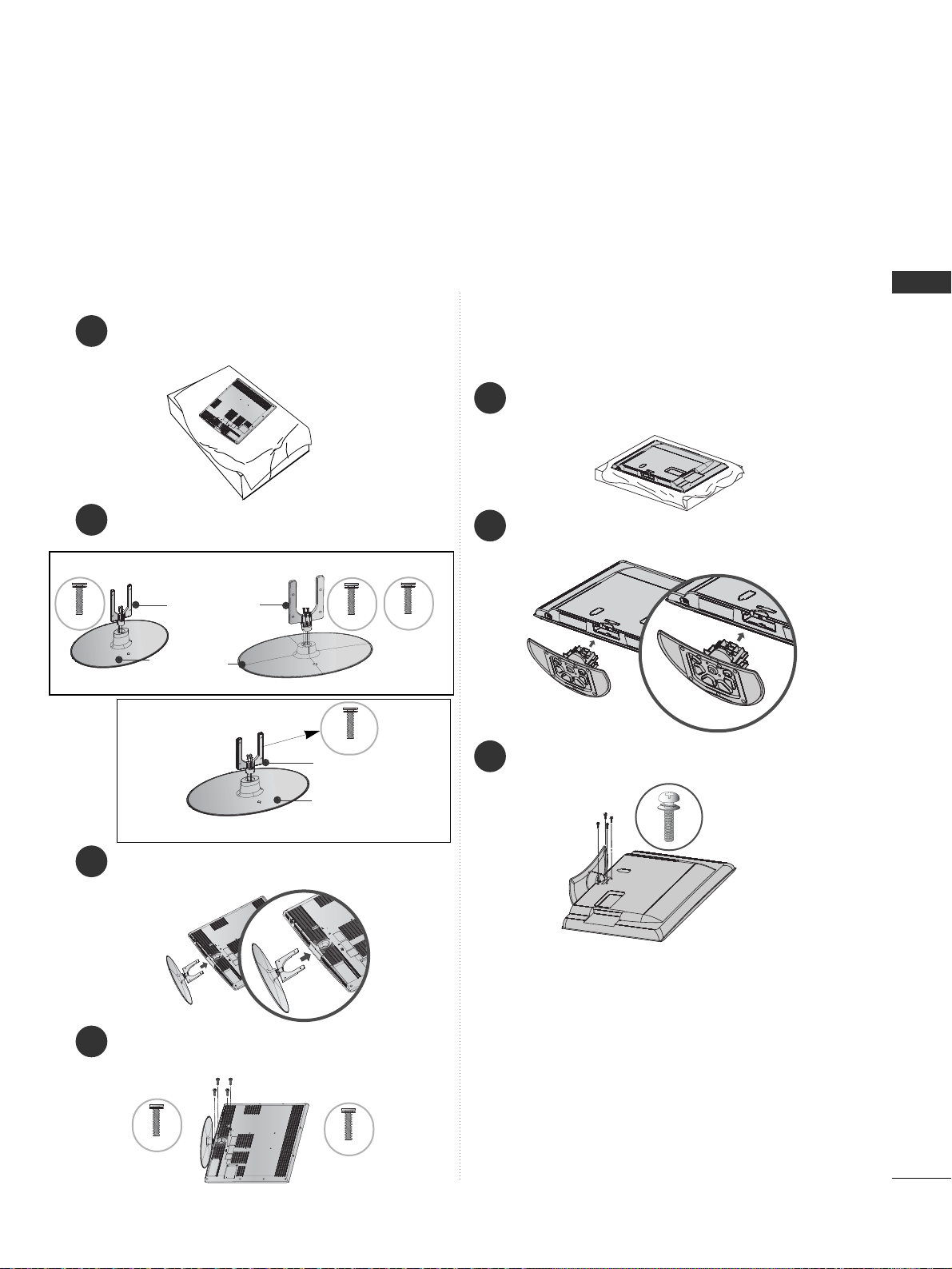
STAND INSTALLATION
1
3
4
Carefully place the TV screen side down on a cushioned surface to protect the screen from damage.
2
Assemble the parts of the
SSttaanndd BB oodd yy
with
the
SStt aanndd BB aassee
of the TV.
Assemble the TV as shown.
Fix the 4 bolts securely using the holes in the
back of the TV.
32LH70
**
Stand Body
Stand Base
42LH70
**
Only 32/37/42/47LH70
**
47 LH 70**37LH70
**
Stand Body
Stand Base
32/37LH70
**
M4x20
M4x20
M4x16
M4x20
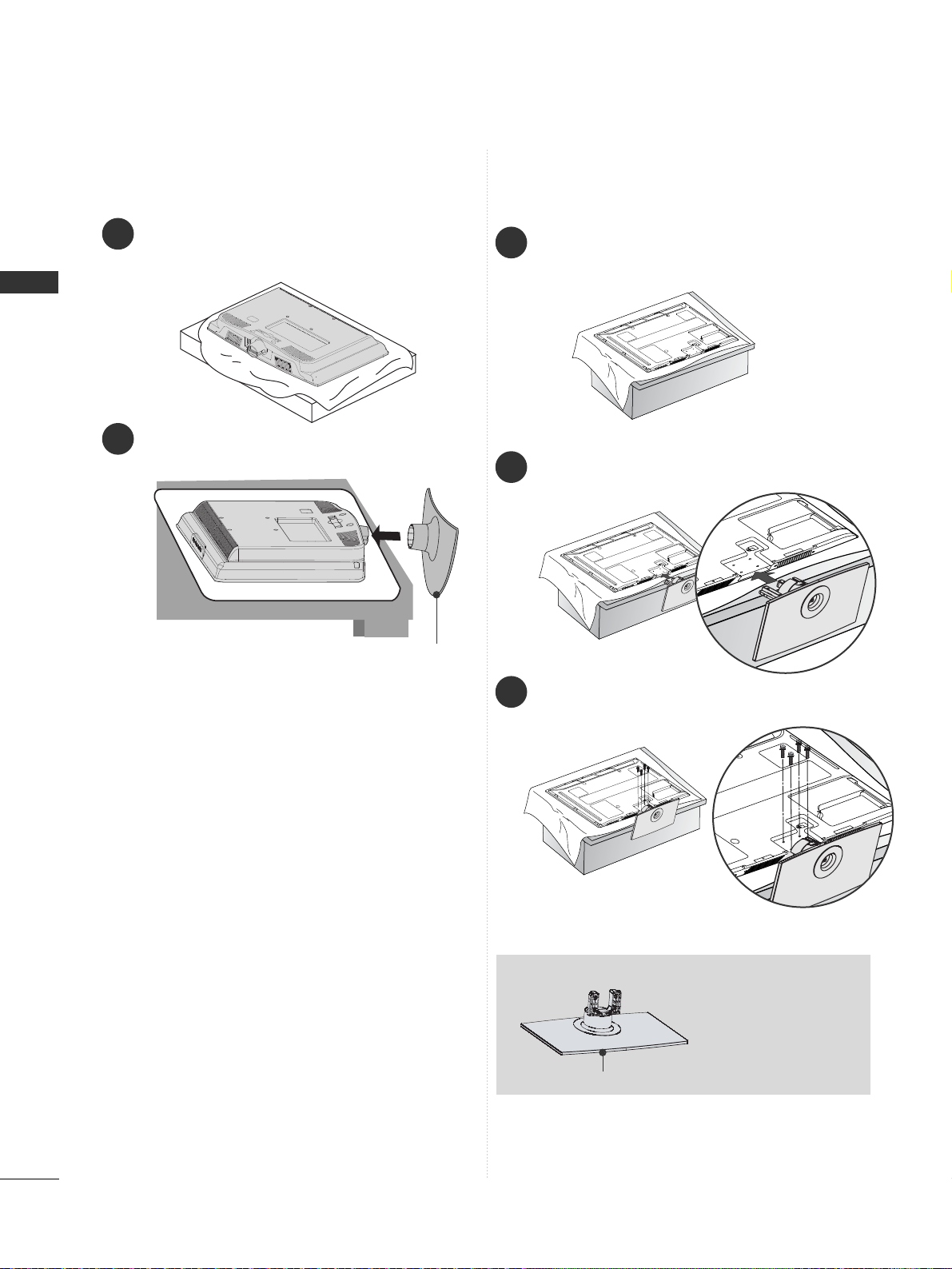
1
2
3
Carefully place the TV screen side down on a cushioned
surface to protect the screen from damage.
Assemble the TV as shown.
Fix the 4 bolts securely using the holes in the
back of the TV.
Only 26/32/37/42LH20**, 26/32LD3**,
32/37/42/47LH3
***
, 32/37/42/47LH40**,
32/37/42/47LH49**, 32/37/42/47LH50**,
42/47LH90
**
M4x20
42/47LH70
**
M4x16
■
Image shown may differ from your TV
When assembling the desk type stand, check whether the bolt is fully tightened. (If not tightened fully, the product can
tilt forward after the product installation.) If you tighten the bolt with excessive force, the bolt can deviate from abrasion
of the tightening part of the bolt.
26
PREPARATION
PREPARATION
Only 50PS70**/50PS80**/
42/50PQ35**/42PQ65**/50PS65
**
1
2
3
Carefully place the TV screen side down on a cushioned
surface to protect the screen from damage.
Assemble the TV as shown.
Fix the 4 bolts securely using the holes in the
back of the TV.
When assembling the
stand, make sure to
distinguish and
assemble the front
and rear side of the
stand correctly.
Front
1
Carefully place the TV screen side down on a cushioned surface to protect the screen from damage.
2
Assemble the TV as shown.
Only 19/22LH20**, 19/22LD3
**
Cover Base
27
PREPARATION
1
2
Carefully place the TV screen side down on a cushioned surface to protect the screen from damage.
Fix the 2 or 3 bolts securely using the holes.
Only 19/22/26LU50
**
(Only 26LU50**)
Only 19/22LG31
**
Stand Body
Cover Base
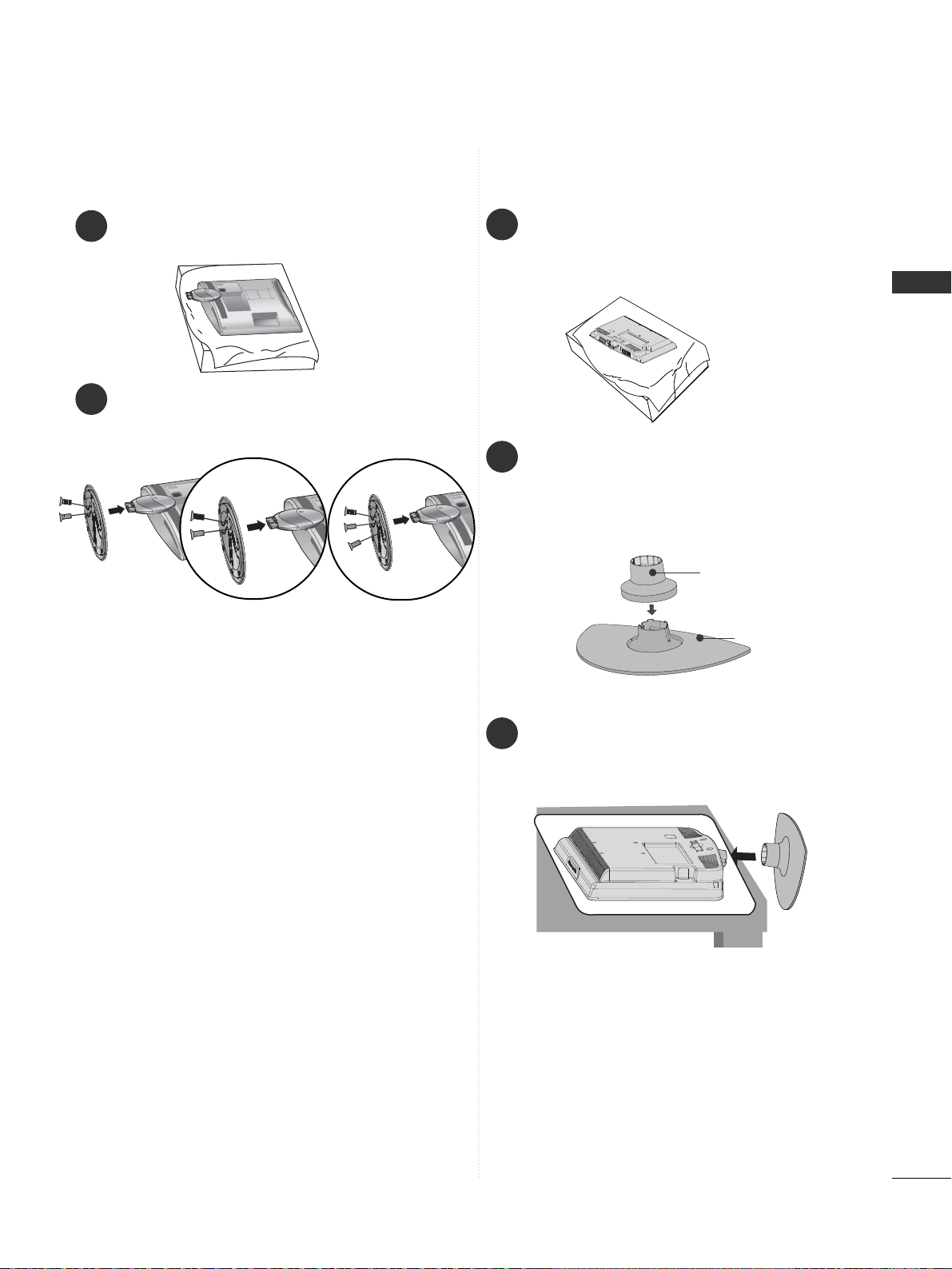
1
2
3
Carefully place the TV screen side down on a
cushioned surface to protect the screen from
damage.
Assemble the parts of the
SSttaanndd BB ooddyy
with
CC oovveerr BBaa ss ee
of the TV. Insert the
SSttaa nndd
BBooddyy
into a
CC oovveerr BBaassee
until clicking sound.
Assemble the TV as shown.
28
PREPARATION
PREPARATION
1
3
4
Carefully place the TV screen side down on a
cushioned surface to protect the screen from
damage.
2
Assemble the parts of the
SSttaanndd BB oodd yy
with
the
CC oovveerr BBaa ssee
of the TV.
Assemble the TV as shown.
Fix the 4 bolts securely using the holes in the
back of the TV.
Stand Body
Cover Base
Only 32/37/42LF25
**,
32/37/42LG2
***,
32/37/42LG33
**,
26LG31
**,
32/42LF51
**
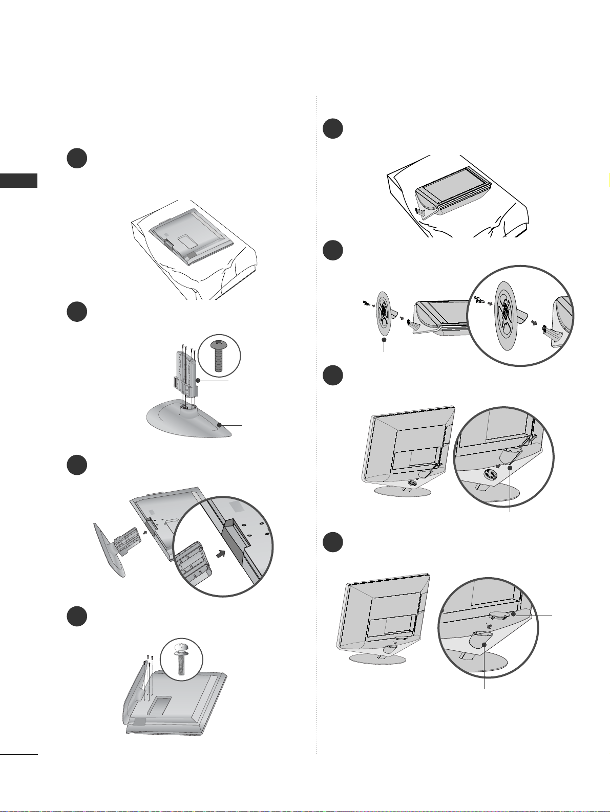
1
3
4
Carefully place the TV screen side down on a cushioned surface to protect the screen from damage.
2
Fix the 3 bolts securely using the holes in the
CC oovveerr BBaa ssee
.
Assemble the parts of the
SSttaanndd RRee aarr BBooddyy
with the TV.
Assemble the parts of the
CC aa pp
with the
SStt aanndd
RReeaarr BBoo ddyy
of the TV.
Only 19/22LU40
**
Stand Rear Body
Cover Base
Stand Rear Body
Cap
 Loading...