

LG 26LD310, 32LD310 Owner's Manual [es]

OWNER’S MANUAL
LCD TV
Please read this manual carefully before operating
your set and retain it for future reference.
22LD310
26LD310
32LD310
P/NO : MFL41469219 (1008-REV03)
www.lg.com
WARNING / CAUTION
TO REDUCE THE RISK OF ELECTRIC SHOCK
DO NOT REMOVE COVER (OR BACK). NO
USER SERVICEABLE PARTS INSIDE. REFER TO
QUALIFIED SERVICE PERSONNEL.
The lightning flash with arrowhead
symbol, within an equilateral triangle, is
intended to alert the user to the presence
of uninsulated “dangerous voltage” within the
product’s enclosure that may be of sufficient
magnitude to constitute a risk of electric shock to
persons.
The exclamation point within an equilateral
triangle is intended to alert the user to
the presence of important operating and
maintenance (servicing) instructions in the literature accompanying the appliance.
WARNING/CAUTION
TO REDUCE THE RISK OF FIRE AND ELECTRIC
SHOCK, DO NOT EXPOSE THIS PRODUCT TO
RAIN OR MOISTURE.
2
SAFETY INSTRUCTIONS
IMPORTANT SAFETY INSTRUCTIONS
Read these instructions.
Keep these instructions.
Heed all warnings.
Follow all instructions.
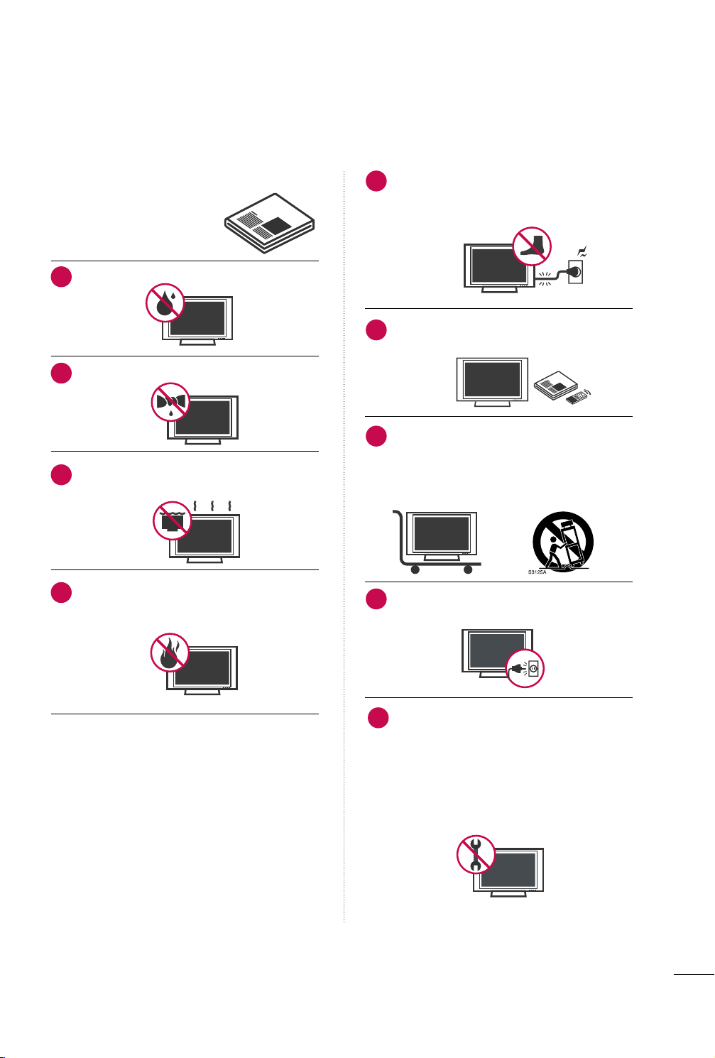
Do not use this apparatus near water.
1
Clean only with dry cloth.
2
Do not block any ventilation openings. Install in
3
accordance with the manufacturer’s instructions.
Do not install near any heat sources such as
4
radiators, heat registers, stoves, or other
apparatus (including amplifiers) that produce
heat.
Protect the power cord from being walked on
5
or pinched particularly at plugs, convenience
receptacles, and the point where they exit from
the apparatus.
Only use attachments/accessories specified by
6
the manufacturer.
Use only with the cart, stand, tripod, bracket,
7
or table specified by the manufacturer, or sold
with the apparatus. When a cart is used, use
caution when moving the cart/apparatus combination to avoid injury from tip-over.
Unplug this apparatus during lighting storms
8
or when unused for long periods of time.
Refer all servicing to qualified service personnel.
9
Servicing is required when the apparatus has
been damaged in any way, such as powersupply cord or plug is damaged, liquid has
been spilled or objects have fallen into the
apparatus, the apparatus has been exposed to
rain or moisture, does not operate normally, or
has been dropped.
3
SAFETY INSTRUCTIONS
Never touch this apparatus or antenna during
10
a thunder or lighting storm.
When mounting a TV on the wall, make sure
11
not to install the TV by the hanging power and
signal cables on the back of the TV.
Do not allow an impact shock or any objects to
12
fall into the product, and do not drop onto the
screen with something.
CAUTION concerning the Power Cord:
13
It is recommend that appliances be placed
upon a dedicated circuit; that is, a single
outlet circuit which powers only that appliance
and has no additional outlets or branch
circuits. Check the specification page of this
owner's manual to be certain.
Do not connect too many appliances to the
same AC power outlet as this could result in
fire or electric shock.
Do not overload wall outlets. Overloaded wall
outlets, loose or damaged wall outlets, extension
cords, frayed power cords, or damaged or
cracked wire insulation are dangerous. Any of
these conditions could result in electric shock
or fire. Periodically examine the cord of your
appliance, and if its appearance indicates damage
or deterioration, unplug it, discontinue use of
the appliance, and have the cord replaced with
an exact replacement part by an authorized
servicer. Protect the power cord from physical
or mechanical abuse, such as being twisted,
kinked, pinched, closed in a door, or walked
upon. Pay particular attention to plugs, wall
outlets, and the point where the cord exits the
appliance.
Do not make the TV with the power cord
plugged in. Do not use a damaged or loose
power cord. Be sure do grasp the plug when
unplugging the power cord. Do not pull on the
power cord to unplug the TV.
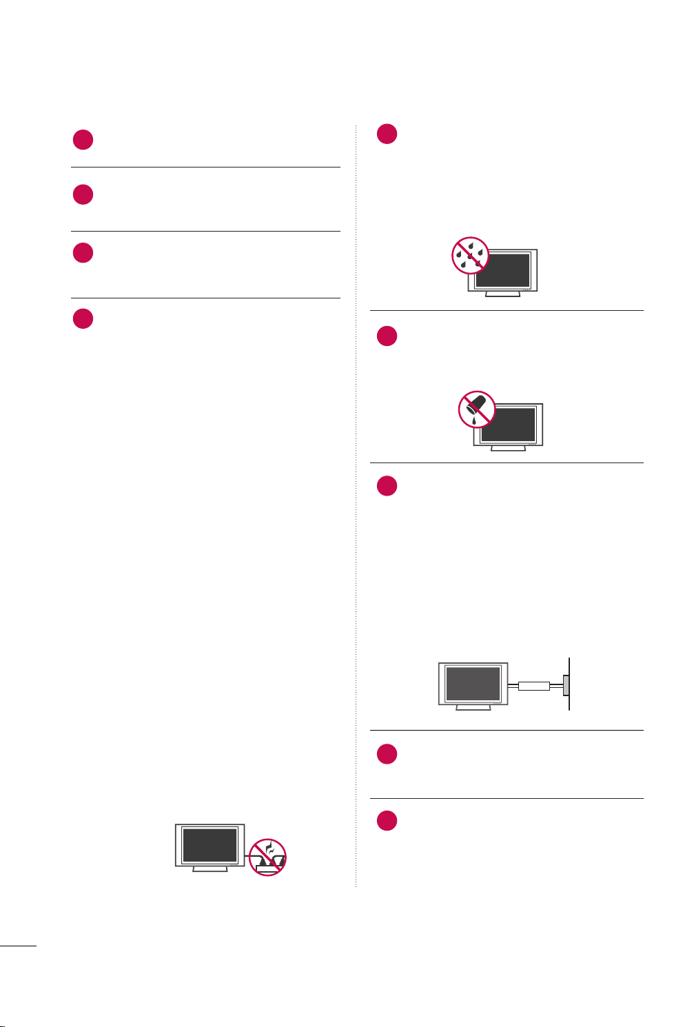
WARNING - To reduce the risk of fire or electrical
14
shock, do not expose this product to rain,
moisture or other liquids. Do not touch the TV
with wet hands. Do not install this product
near flammable objects such as gasoline or
candles or expose the TV to direct air
conditioning.
Do not expose to dripping or splashing and do
15
not place objects filled with liquids, such as
vases, cups, etc. on or over the apparatus (e.g.
on shelves above the unit).
GGRROOUUNN DDIINNGG
16
Ensure that you connect the earth ground wire
to prevent possible electric shock (i.e. a TV
with a three-prong grounded AC plug must be
connected to a three-prong grounded AC outlet). If grounding methods are not possible,
have a qualified electrician install a separate
circuit breaker.
Do not try to ground the unit by connecting it
to telephone wires, lightening rods, or gas
pipes.
Short-circuit
Breaker
DDIISSCCOONNNNEECCTTIINNGG DDEEVVIICCEE FFRROOMM MMAAIINNSS
17
Mains plug is the disconnecting device. The
plug must remain readily operable.
Power
Supply
As long as this unit is connected to the AC wall
18
outlet, it is not disconnected from the AC
power source even if you turn off this unit by
SWITCH.
4
CClleeaanniinngg
19
When cleaning, unplug the power cord and rub
gently with a soft cloth to prevent scratching.
Do not spray water or other liquids directly on
the TV as electric shock may occur. Do not
clean with chemicals such as alcohol, thinners
or benzene.
MMoovv iinngg
20
Make sure the product is turned off,
unplugged and all cables have been removed. It
may take 2 or more people to carry larger TVs.
Do not press against or put stress on the front
panel of the TV.
VVeennttiillaattiioo nn
21
Install your TV where there is proper ventilation. Do not install in a confined space such as
a bookcase. Do not cover the product with
cloth or other materials (e.g.) plastic while
plugged in. Do not install in excessively dusty
places.
Take care not to touch the ventilation open-
22
ings. When watching the TV for a long period,
the ventilation openings may become hot.
If you smell smoke or other odors coming from
23
the TV, unplug the power cord and contact an
authorized service center.
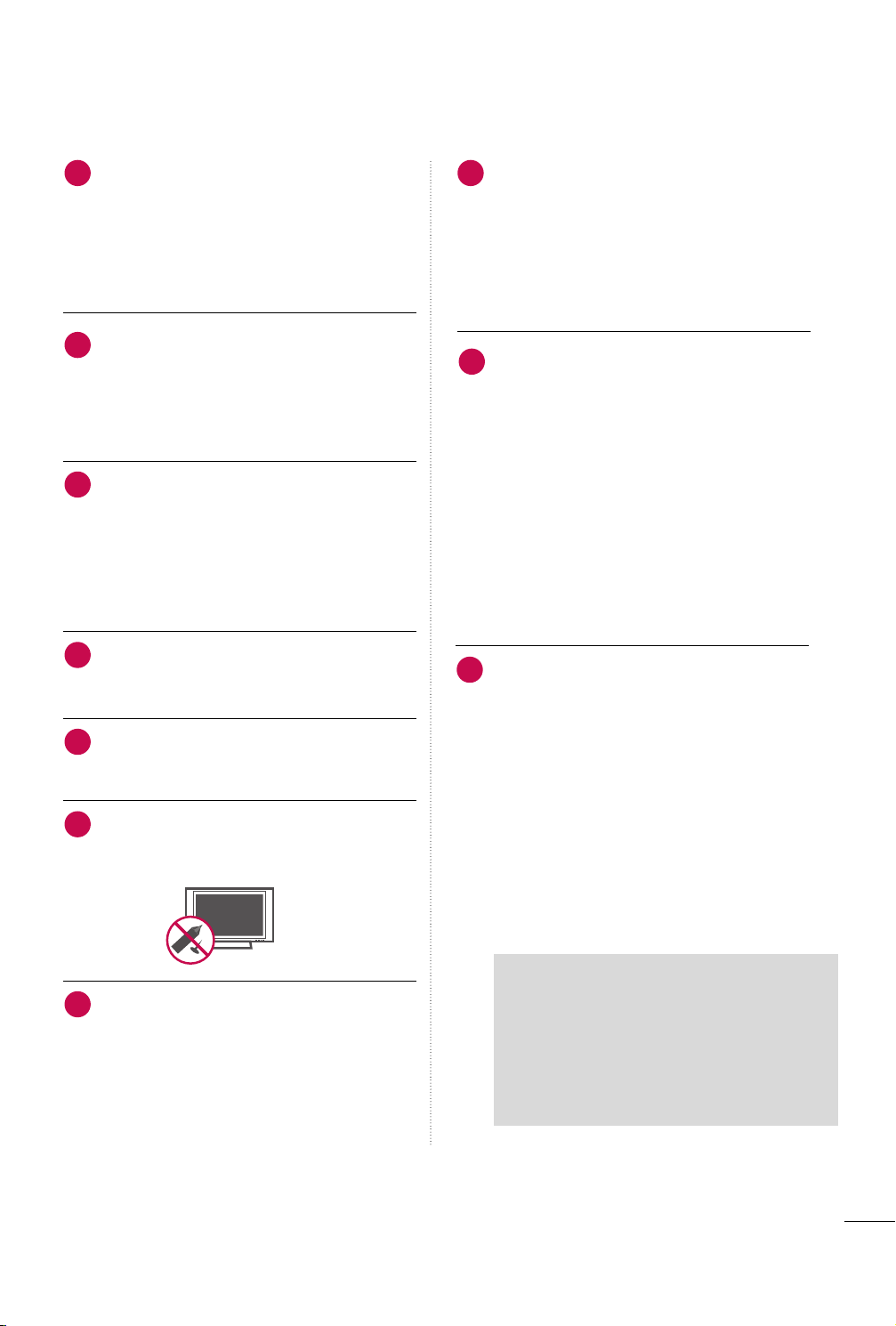
No presione en exceso el panel con sus manos u
24
objetos afilados, como tornillos, lápices o bolígrafos, y evite rayarlo.
DDoott DD eeffeecc tt
26
The Plasma or LCD panel is a high technology
product with resolution of two million to six
million pixels. In a very few cases, you could see
fine dots on the screen while you’reviewing the
TV. Those dots are deactivated pixels and do
not affect the performance and reliability of
the TV.
GGeenneerraatteedd SSoouunndd
27
“Cracking” noise: A cracking noise that occurs
when watching or turning off the TV is generated by plastic thermal contraction due to
temperature and humidity. This noise is common for products where thermal deformation
is required.
Electrical circuit humming/panel buzzing: A low
level noise is generated from a high-speed
switching circuit, which supplies a large
amount of current to operate a product. It
varies depending on the product.This generated sound does not affect the performance and
reliability of the product.
FFoorr LLCCDD TT VV
28
If the TV feels cold to the touch, there may be
a small “flicker” when it is turned on. This is
normal, there is nothing wrong with TV.
Some minute dot defects may be visible on the
screen, appearing as tiny red, green, or blue
spots. However, they have no adverse effect on
the monitor's performance.
Avoid touching the LCD screen or holding your
finger(s) against it for long periods of time.
Doing so may produce some temporary distortion effects on the screen.
Keep the product away from direct sunlight.
25
ON DISPOSAL
(Only Hg lamp used LCD TV)
The fluorescent lamp used in this product contains
a small amount of mercury. Do not dispose of
this product with general household waste.
Disposal of this product must be carried out in
accordance to the regulations of your local authority.
5

CONTENTS
WARNING / CAUTION
SAFETY INSTRUCTIONS
FEATURE OF THIS TV
. . . . . . . . . . . . . . . . . . . . . . . . . . . . 2
. . . . . . . . . . . . . . . . . . . . . . . . . . 3
. . . . . . . . . . . . . . . . . . . . . . . . . . . . . . . 8
PREPARATION
Accessories . . . . . . . . . . . . . . . . . . . . . . . . . . . . . . . . . . . . . . . . . . . . . . . . . . . . . . 9
Front Panel Information
. . . . . . . . . . . . . . . . . . . . . . . . . . . . . . . . . . .10
Back Panel Information . . . . . . . . . . . . . . . . . . . . . . . . . . . . . . . . . . . . .11
Stand Instructions
. . . . . . . . . . . . . . . . . . . . . . . . . . . . . . . . . . . . . . . . . . . 12
VESA Wall Mounting . . . . . . . . . . . . . . . . . . . . . . . . . . . . . . . . . . . . . . . . 14
Cable Management . . . . . . . . . . . . . . . . . . . . . . . . . . . . . . . . . . . . . . . . .
Desktop Pedestal Installation
Swivel Stand
. . . . . . . . . . . . . . . . . . . . . . . . . . . . . . . . . . . . . . . . . . . . . . . . . . . .16
Positioning your Display
. . . . . . . . . . . . . . . . . . . . . . . . . . . . 16
. . . . . . . . . . . . . . . . . . . . . . . . . . . . . . . . . . .16
15
Attaching the TV to a Desk . . . . . . . . . . . . . . . . . . . . . . . . . . . . . . 17
Kensington Security System
. . . . . . . . . . . . . . . . . . . . . . . . . . . . .17
Securing the TV to the wall to prevent falling when
the TV is used on a stand
. . . . . . . . . . . . . . . . . . . . . . . . . . . . . . . . 18
Antenna or Cable Connection . . . . . . . . . . . . . . . . . . . . . . . . . .19
EXTERNAL EQUIPMENT SETUP
HD Receiver Setup . . . . . . . . . . . . . . . . . . . . . . . . . . . . . . . . . . . . . . . . .20
DVD Setup
VCR Setup . . . . . . . . . . . . . . . . . . . . . . . . . . . . . . . . . . . . . . . . . . . . . . . . . . . . .24
Other A/V Source Setup
External Stereo Setup . . . . . . . . . . . . . . . . . . . . . . . . . . . . . . . . . . . . . .25
. . . . . . . . . . . . . . . . . . . . . . . . . . . . . . . . . . . . . . . . . . . . . . . . . . . . .22
. . . . . . . . . . . . . . . . . . . . . . . . . . . . . . . . . 25
Fine Tuning Adjustment
Favorite Channels Setup
. . . . . . . . . . . . . . . . . . . . . . . . . . . . . . . . . . .32
. . . . . . . . . . . . . . . . . . . . . . . . . . . . . . . . . . 33
Key Lock . . . . . . . . . . . . . . . . . . . . . . . . . . . . . . . . . . . . . . . . . . . . . . . . . . . . . . . . . 34
Factory Reset
. . . . . . . . . . . . . . . . . . . . . . . . . . . . . . . . . . . . . . . . . . . . . . . . . . 34
PICTURE CONTROL
Picture Size (Aspect Ratio) Control . . . . . . . . . . . . . . . . . .35
Preset Picture Settings (Picture Mode Preset)
Manual Picture Adjustment
Picture Improvement Technology
Picture Reset
Screen Setup
. . . . . . . . . . . . . . . . . . . . . . . . . . . . . . . . . . . . . . . . . . . . . . . . . 40
. . . . . . . . . . . . . . . . . . . . . . . . . . . . . . . . . . . . . . . . . . . . . . . . . . 41
. . . . . . . . . . . . . . . . . . . . . . . . . . . . . .37
. . . . . . . . . . . . . . . . . . . . . 38
. . . 36
SOUND & LANGUAGE CONTROL
Preset Sound Settings - Sound Mode . . . . . . . . . . . . . . . 43
Sound Setting Adjustment - User Mode
Audio Reset
. . . . . . . . . . . . . . . . . . . . . . . . . . . . . . . . . . . . . . . . . . . . . . . . . . . 45
Auto Volume Leveler (Auto Volume)
Balance
Stereo/SAP Broadcasts Setup
. . . . . . . . . . . . . . . . . . . . . . . . . . . . . . . . . . . . . . . . . . . . . . . . . . . . . . . . . .47
. . . . . . . . . . . . . . . . . . . . . . . . . . 48
On-Screen Menus Language Selection
Power Indicator
Closed Captions
. . . . . . . . . . . . . . . . . . . . . . . . . . . . . . . . . . . . . . . . . . . . . . .50
. . . . . . . . . . . . . . . . . . . . . . . . . . . . . . . . . . . . . . . . . . . . . 51
. . . . . . . . . . .44
. . . . . . . . . . . . . . . . .46
. . . . . . . . . . . . .
49
WATCHING TV / CHANNEL CONTROL
Remote Control Functions . . . . . . . . . . . . . . . . . . . . . . . . . . . . . . . 26
Turning On the TV
Channel Selection
. . . . . . . . . . . . . . . . . . . . . . . . . . . . . . . . . . . . . . . . . .
. . . . . . . . . . . . . . . . . . . . . . . . . . . . . . . . . . . . . . . . . . .
28
28
Volume Adjustment . . . . . . . . . . . . . . . . . . . . . . . . . . . . . . . . . . . . . . . . . 28
On-Screen Menus Selection
. . . . . . . . . . . . . . . . . . . . . . . . . . . . 29
Channel Search
- Auto Tuning . . . . . . . . . . . . . . . . . . . . . . . . . . . . . . . . . . . . . . . . . . . . . .30
- Manual Tuning
. . . . . . . . . . . . . . . . . . . . . . . . . . . . . . . . . . . . . . . . . . 31
6

TIME SETTING
Clock Setup . . . . . . . . . . . . . . . . . . . . . . . . . . . . . . . . . . . . . . . . . . . . . . . . . . . . 52
Auto On/Off Time Setting
Sleep Timer Setting
. . . . . . . . . . . . . . . . . . . . . . . . . . . . . .53
. . . . . . . . . . . . . . . . . . . . . . . . . . . . . . . . . . . . . . . . .54
APPENDIX
Troubleshooting . . . . . . . . . . . . . . . . . . . . . . . . . . . . . . . . . . . . . . . . . . . . . . 55
Maintenance
Product Specifications . . . . . . . . . . . . . . . . . . . . . . . . . . . . . . . . . . . . . 58
IR Codes
. . . . . . . . . . . . . . . . . . . . . . . . . . . . . . . . . . . . . . . . . . . . . . . . . . . 57
. . . . . . . . . . . . . . . . . . . . . . . . . . . . . . . . . . . . . . . . . . . . . . . . . . . . . . . . 59
7
FEATURE OF THIS TV
HDMI, the HDMI logo and High-Definition
Multimedia Interface are trademarks or registered
trademarks of HDMI Licensing LLC."
LG TV include a unique invisible speaker system,
tuned by renowned audio expert, Mr. Mark Levinson.
Speakers are embedded in strategic spots behind the
front cabinet and use minute vibrations to turn the
entire front bezel into the speaker system. The result
is a clean, polished look, and enhanced audio by
increasing the “sweet spot”, giving a wider and richer
sound field.
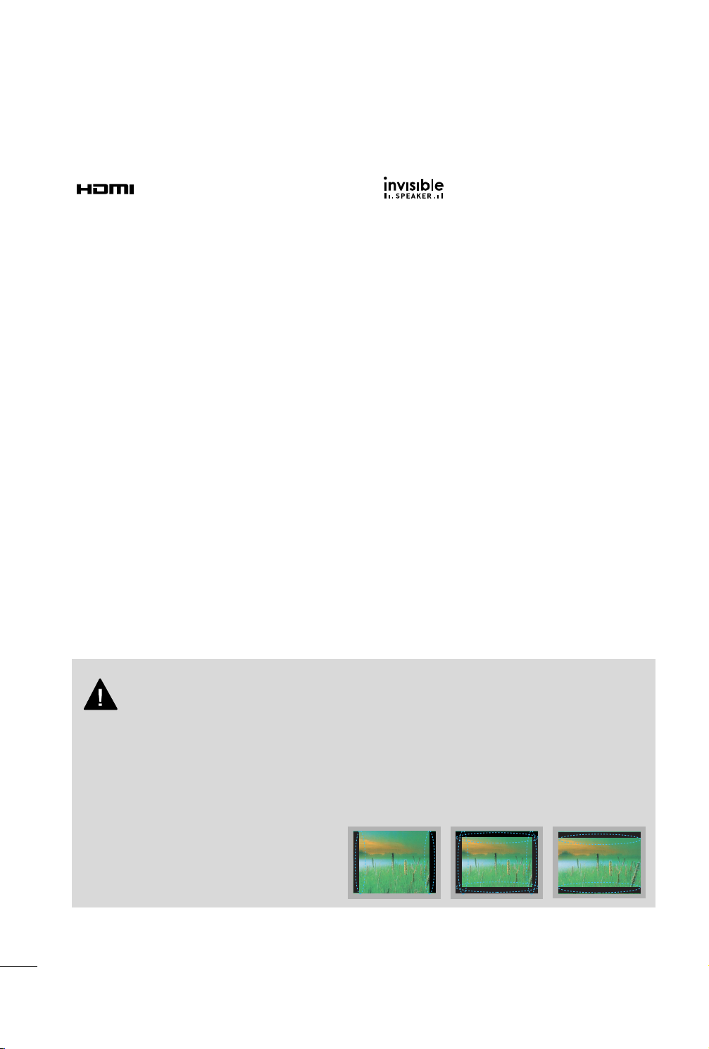
IMPORTANT INFORMATION TO PREVENT “IMAGE BURN
/ BURN-IN” ON YOUR TV SCREEN
■
When a fixed image (e.g. logos, screen menus, video game, and computer display) is displayed on the TV
for an extended period, it can become permanently imprinted on the screen. This phenomenon is known
as “image burn” or “burn-in.” Image burn is not covered under the manufacturer’s warranty.
■
In order to prevent image burn, avoid displaying a fixed image on your TV screen for a prolonged period
(2 or more hours for LCD, 1 or more hours for Plasma).
■
Image burn can also occur on the letterboxed
areas of your TV if you use the 4:3 aspect ratio
setting for an extended period.
8
PREPARATION
1.5V 1.5V
123
456
78
0
9
V
O
L
V
O
L
CH
CH
ENTER
MENU Q.VIEW SLEEP
SOUND RATIO
FAV
MUTE
O
G
MEMORY/ERASE
CAPTION
INPUT
123
456
78
0
9
V
O
L
V
O
L
CH
CH
ENTER
POWER
MENU Q.VIEW SLEEP
RATIO
MTS
FAV
MUTE
A
.P
R
O
G
CAPTION
TV INPUT
MEMORY/ERASE
SOUNDPICTURE
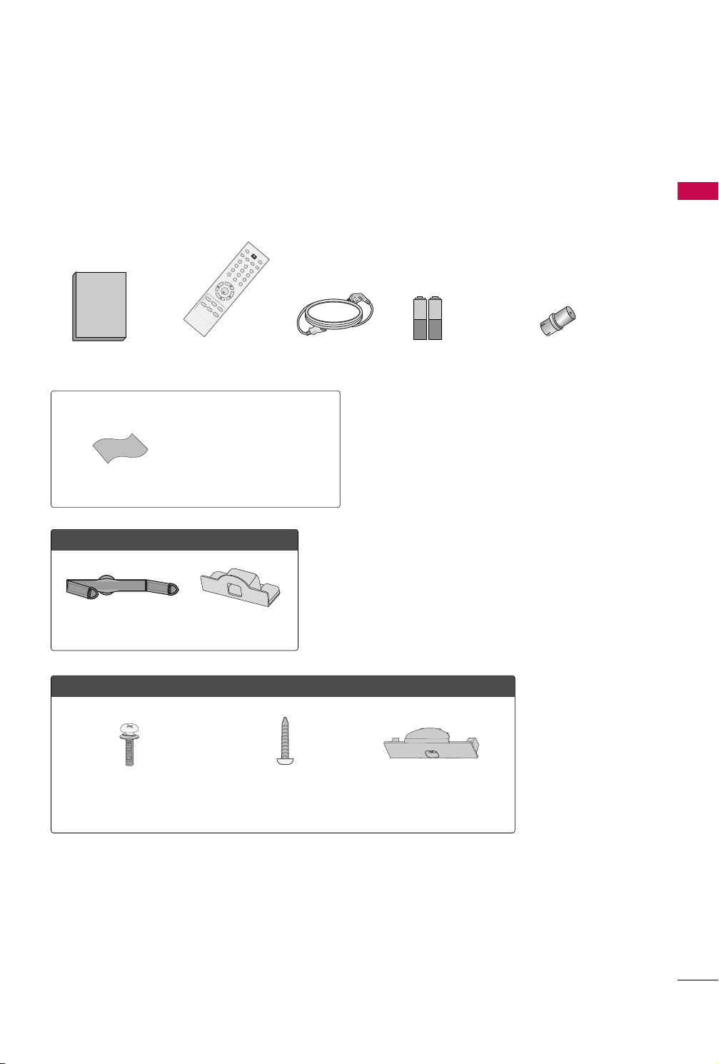
ACCESSORIES
Ensure that the following accessories are included with your TV. If an accessory is missing, please contact the
dealer where you purchased the TV.
The accessories included may differ from the images below.
PREPARATION
Owner’s Manual
Not included with all models
* Wipe spots on the exterior only with
* Do not wipe roughly when removing
Polishing Cloth
FFoorr 2222LLDD331100
Cable Management Clip
OOnnllyy 2266//3322LLDD331100
x 4
Remote Control
Power Cord
the polishing cloth.
stains. Excessive pressure may cause
scratches or discoloration.
Protection Cover
Batteries
(Some models)
RF Adapter
(Some models)
You must connect it to the antenna
wire after fixing in Antenna Input.
This adapter is For supplied in
AArrgg eenn ttiinn aa
.
(M4x24)
Screw for stand fixing Protection Cover
Bolts for stand assembly
9
PREPARATION
INPUT
MENU
ENTER
CH
VOL
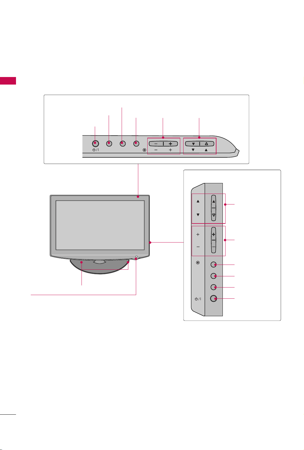
FRONT PANEL INFORMATION
■
Image shown may differ from your TV.
PREPARATION
22/26LD310
POWER Button
INPUT Button
MENU Button
ENTER
Button
VOLUME
(-, +) Buttons
CHANNEL
EE,DD
) Buttons
(
INPUT MENU
SPEAKER
Remote Control Sensor,
Power/Standby Indicator
Illuminates red in standby mode.
Illuminates blue when the TV is switched on.
(Can be adjusted
OPTION menu.
PP oowweerr IInn ddiiccaattoorr
pp..5500
)
GG
in the
ENTER
VOL
CH
32LD310
CHANNEL (DD,EE)
Buttons
VOLUME (+, -)
Buttons
ENTER Button
MENU Button
INPUT Button
POWER Button
10
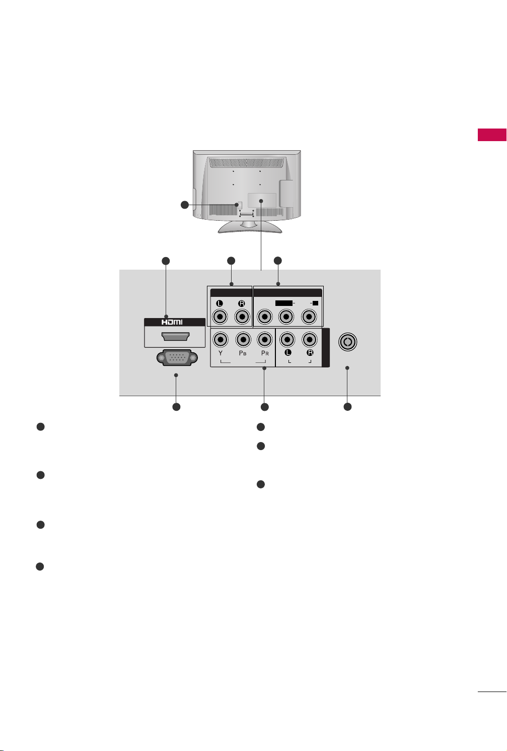
BACK PANEL INFORMATION
IN
SERVICE ONLY
AUDIOVIDEO
ANTENNA
IN
COMPONENT IN
AUDIO OUT
VIDEO
AUDIOAUDIO
L( MONO)
R
AV IN
■
Image shown may differ from your TV.
1
PREPARATION
2
5
1
Power Cord Socket
This TV operates on an AC power. The voltage is
indicated on the Specifications page. Never
attempt to operate the TV on DC power.
2
HDMI Input
Connect a HDMI signal to HDMI IN.
This TV does not support DVI(VIDEO) signal
using DVI to HDMI cable.
3
Audio Output
Connect an external amplifier, or add a subwoofer
to your surround sound system.
3
4
6
5
SERVICE ONLY PORT
Component Input
6
7
Connect a component video/audio device to
these jacks.
Antenna Input
7
Connect RF antenna to this jack.
Audio/Video Input (AV IN)
4
Connect audio/video output from an external
device to these jacks.
11
PREPARATION
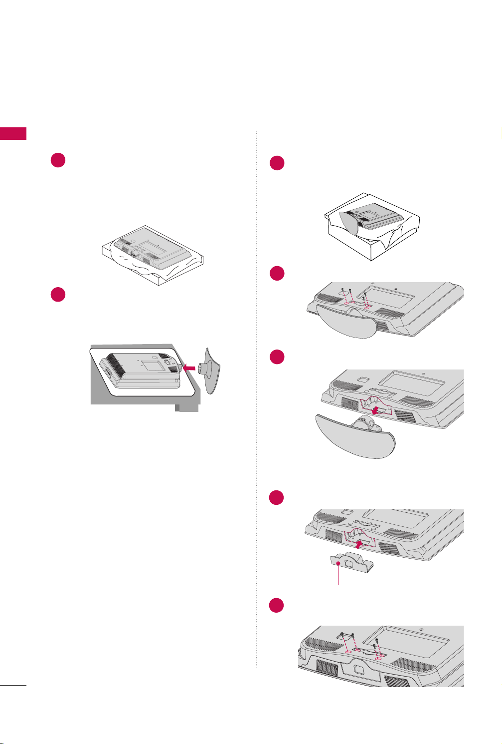
STAND INSTRUCTIONS (For 22LD310)
■
Image shown may differ from your TV.
PREPARATION
INSTALLATION
Carefully place the TV screen side down on a
1
cushioned surface to protect the screen from
damage.
Assemble the TV as shown until you hear it click.
2
DETACHMENT
Carefully place the TV screen side down on a
1
cushioned surface to protect the screen from
damage.
Loose the bolts from TV.
2
Detach the stand from TV.
3
12
PROTECTION COVER
Insert the
4
Fix the 4 bolts securely using the holes in the
5
back of the TV.
PPRROOTTEECCTT IIOONN CCOOVVEERR
PPRROOTTEECCTT IIOONN CCOOVVEERR
into the TV.
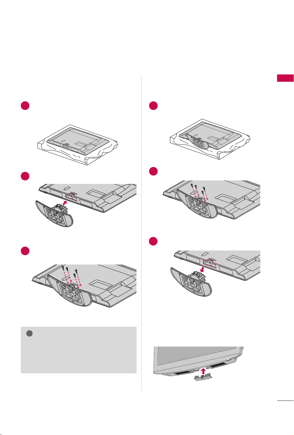
STAND INSTRUCTIONS (For 26/32LD310)
!
INSTALLATION
DETACHMENT
PREPARATION
Carefully place the TV screen side down on a
1
cushioned surface to protect the screen from
damage.
Assemble the TV as shown.
2
Fix the 4 bolts securely using the holes in the
3
back of the TV.
Carefully place the TV screen side down on a
1
cushioned surface to protect the screen from
damage.
Loose the bolts from TV.
2
Detach the stand from TV.
3
PROTECTION COVER
After removing the stand, install the included
pprroo tt eeccttiioo nn ccoo vv eerr
NOTE
When assembling the desk type stand, make sure
GG
the bolt is fully tightened (If not tightened fully,
the TV can tilt forward after the product installation). Do not over tighten.
Press the
until you hear it click.
PPRROOTTEECCTTIIOONN CCOOVVEERR
over the hole for the stand.
into the TV
13
PREPARATION
!
AA
BB
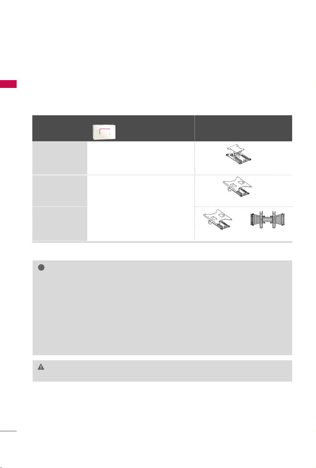
VESA WALL MOUNTING
Install your wall mount on a solid wall perpendicular to the floor. When attaching to other building materials, please
contact your nearest installer.
PREPARATION
If installed on a ceiling or slanted wall, it may fall and result in severe personal injury.
We recommend that you use an LG brand wall mount when mounting the TV to a wall.
LG recommends that wall mounting be performed by a qualified professional installer.
VESA (A *B)
Model
22LD310
26LD310
32LD310
10 0* 10 0 M 4 4
200* 10 0 M 4 4
Standard Screw Quantity
NOTE
Screw length needed depends on the wall mount
GG
used. For further information, refer to the instructions included with the mount.
Standard dimensions for wall mount kits are shown
GG
in the table.
When purchasing our wall mount kit, a detailed
GG
installation manual and all parts necessary for
assembly are provided.
Do not use screws longer then the standard dimen-
GG
sion, as they may cause damage to the inside to
the TV.
For wall mounts that do not comply with the VESA
GG
Wall Mounting Bracket
(sold separately)
RW120
RW230
RW230 AW-47LG30M
standard screw specifications, the length of the
screws may differ depending on their specifications.
Do not use screws that do not comply with the
GG
VESA standard screw specifications.
Do not use fasten the screws too strongly, this may
damage the TV or cause the TV to a fall, leading to
personal injury. LG is not liable for these kinds of
accidents.
LG is not liable for TV damage or personal injury
GG
when a non-VESA or non specified wall mount is
used or the consumer fails to follow the TV installation instructions.
Do not install your wall mount kit while your TV is turned on. It may result in personal
CAUTION
GG
injury due to electric shock.
14
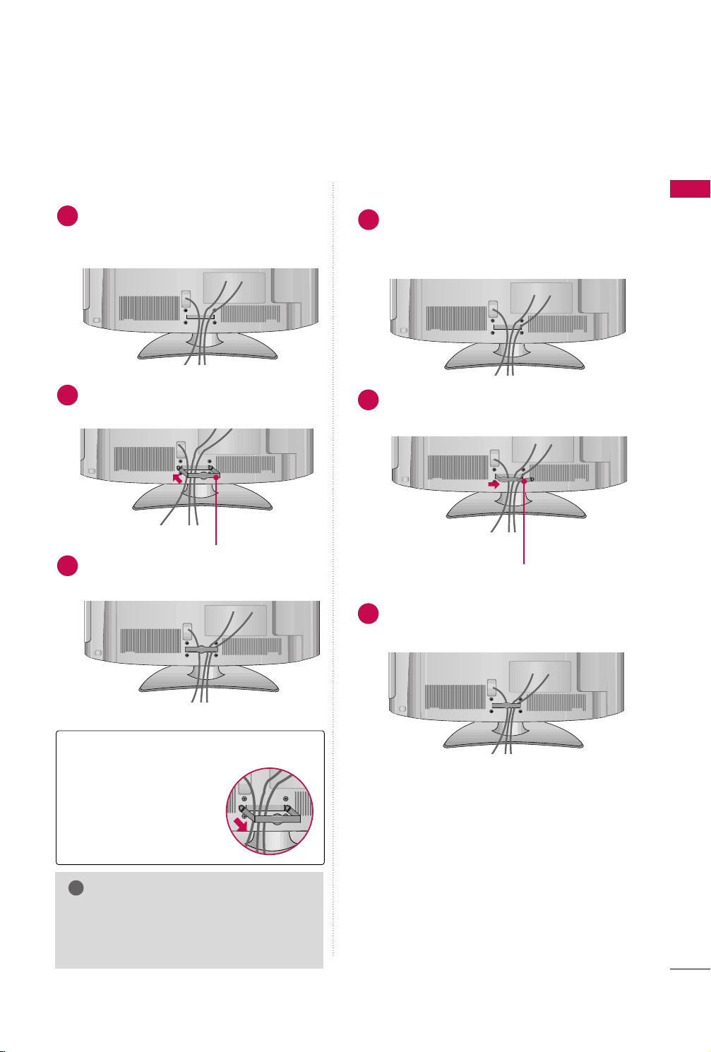
CABLE MANAGEMENT
!
■
Image shown may differ from your TV.
For 22LD310
Connect the cables as necessary.
1
To connect additional equipment, see the
EXTERNAL EQUIPMENT SETUP section.
Install the CABLE MANAGEMENT CLIP as
2
shown.
CABLE MANAGEMENT CLIP
Fit the CABLE MANAGEMENT CLIP as
3
shown.
For 26/32LD310
Connect the cables as necessary.
1
To connect additional equipment, see the
EXTERNAL EQUIPMENT SETUP section.
Install the CABLE MANAGEMENT CLIP as
2
shown.
CABLE MANAGEMENT CLIP
PREPARATION
How to remove the CABLE
MANAGEMENT CLIP
Hold the CABLE MAN-
GG
AGEMENT CLIP with
both hands and pull it
backward.
NOTE
Do not hold the CABLE MANAGEMENT
GG
CLIP when moving the TV.
- If the TV is dropped, you may be injured or
the product may be broken.
Put the cables inside the CABLE MANAGE-
3
MENT CLIP and snap it closed.
15
PREPARATION
12
0
3
0
DESKTOP PEDESTAL INSTALLATION
■
Image shown may differ from your TV.
PREPARATION
For proper ventilation, allow a clearance of 4 inches on all four sides from the wall.
CAUTION
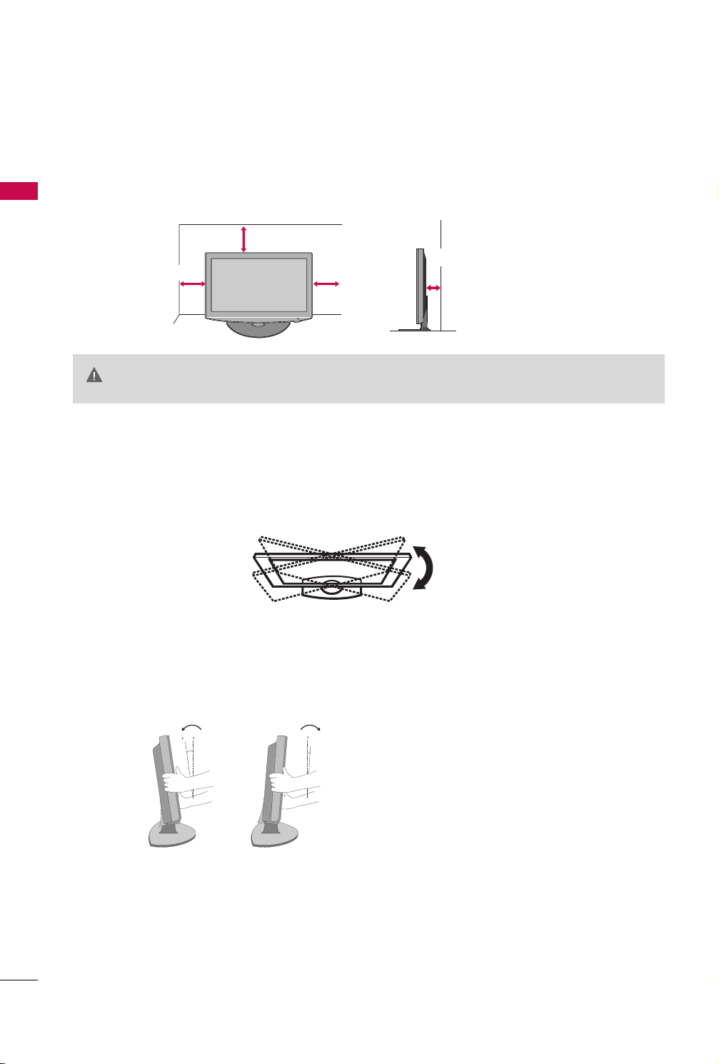
SWIVEL STAND (Except 22LD310)
After installing the TV, you can adjust the TV set manually to the left or right direction by 20 degrees to suit
your viewing position.
4 inches
4 inches
4 inches
Ensure adequate ventilation by following the clearance recommendations.
GG
Do not mount near or above any type of heat source.
GG
4 inches
16
POSITIONING YOUR DISPLAY (For 22LD310)
■
Here shown may be somewhat different from your TV.
■
Adjust the position of the panel in various ways for maximum comfort.
• Tilt range
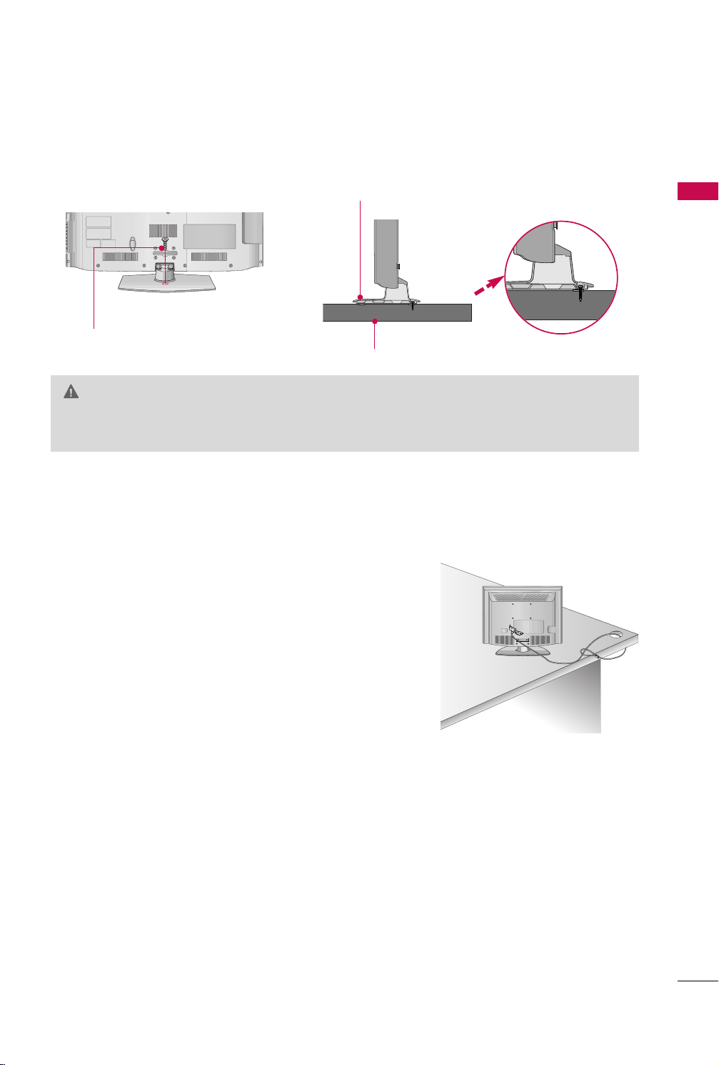
ATTACHING THE TV TO A DESK (Except 22LD310)
The TV must be attached to a desk so it cannot be pulled in a forward/backward direction, potentially causing
injury or damaging the product.
Stand
1-Screw
(provided as parts of the product)
Desk
WARNING
To prevent TV from falling over, the TV should be securely attached to the floor/wall per installation
GG
instructions. Tipping, shaking, or rocking the machine may cause injury.
KENSINGTON SECURITY SYSTEM
■
This feature is not available for all models.
PREPARATION
- The TV is equipped with a Kensington Security System connector on
the back panel. Connect the Kensington Security System cable as
shown below.
- For the detailed installation and use of the Kensington Security
System, refer to the user’s guide provided with the Kensington
Security System.
For further information, contact
the internet homepage of the Kensington company. Kensington sells
security systems for expensive electronic equipment such as notebook PCs and LCD projectors.
NOTE: The Kensington Security System is an optional accessory.
hh ttttpp ::////ww wwww..kkeennssiinn ggttoonn ..ccoomm
,
17
PREPARATION
!
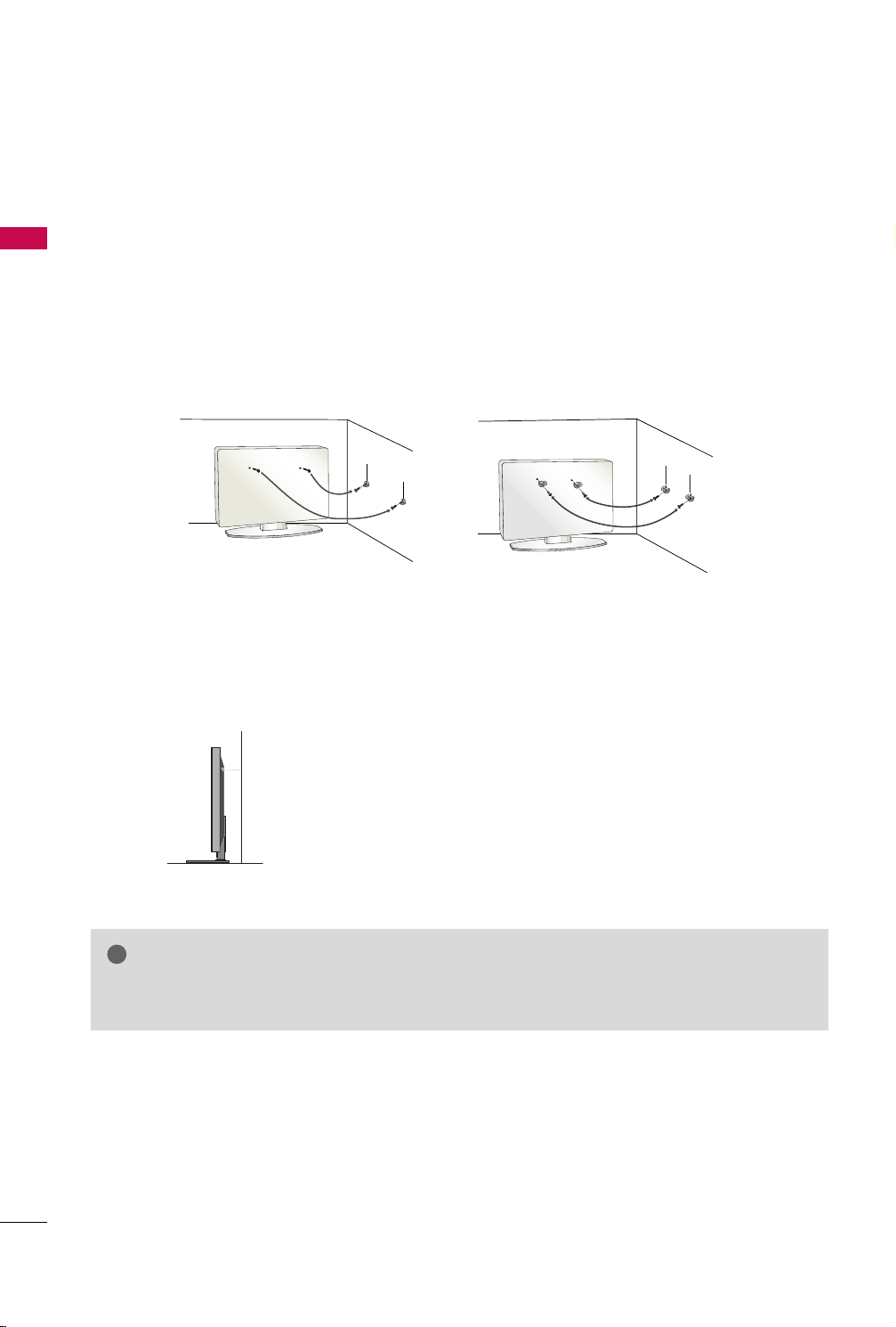
SECURING THE TV TO THE WALL TO PREVENT FALLING
WHEN THE TV IS USED ON A STAND
■
PREPARATION
You should purchase necessary components to prevent the TV from tipping over (when not using a wall mount).
■
Image shown may differ from your TV.
We recommend that you set up the TV close to a wall so it cannot fall over if pushed backwards.
Additionally, we recommend that the TV be attached to a wall so it cannot be pulled in a forward direction,
potentially causing injury or damaging the product.
Caution: Please make sure that children don’t climb on or hang from the TV.
■
Insert the eye-bolts (or TV brackets and bolts) to tighten the product to the wall as shown in the picture.
*If your product has the bolts in the eye-bolts position before inserting the eye-bolts, loosen the bolts.
* Insert the eye-bolts or TV brackets/bolts and tighten them securely in the upper holes.
Secure the wall brackets with the bolts (sold separately) to the wall. Match the height of the bracket that is
mounted on the wall to the holes in the product.
Ensure the eye-bolts or brackets are tightened securely.
18
■
Use a sturdy rope (sold separately) to tie the product. It is safer to tie
the rope so it becomes horizontal between the wall and the product.
NOTE
Use a platform or cabinet strong enough and large enough to support the size and weight of the TV.
GG
To use the TV safely make sure that the height of the bracket on the wall and the one on the TV are the same.
GG
ANTENNA
IN
ANTENNA
IN
■
To prevent damage do not connect to the power outlet until all connections are made between the devices.
■
Image shown may differ from your TV.
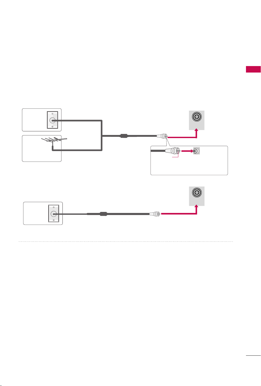
ANTENNA OR CABLE CONNECTION
1. Antenna (Analog)
Wall Antenna Socket or Outdoor Antenna without a Cable Box
Connections.
For optimum picture quality, adjust antenna direction if needed.
Wall
Multi-family Dwellings/Apartments
(Connect to wall antenna socket)
Antenna
Socket
Outdoor
RF Coaxial Wire (75 ohm)
Antenna
(VHF, UHF)
Single-family Dwellings /Houses
(Connect to wall jack for outdoor antenna)
2. Cable
Cable TV
Wall Jack
RF Coaxial Wire (75 ohm)
PREPARATION
Copper Wire
Be careful not to bend the copper wire
when connecting the antenna.
■
To improve the picture quality in a poor signal area, please purchase a signal amplifier and install properly.
■
If the antenna needs to be split for two TV’s, install a 2-Way Signal Splitter.
■
If the antenna is not installed properly, contact your dealer for assistance.
19
EXTERNAL EQUIPMENT SETUP
IN
SERVICE ONLY
ANTENNA
IN
AUDIO OUT
VIDEO
AUDIO
L(MONO)
R
AV IN
AUDIO
VIDEO
COMPONENT IN
■
To prevent the equipment damage, never plug in any power cords until you have finished connecting all equipment.
HD RECEIVER SETUP
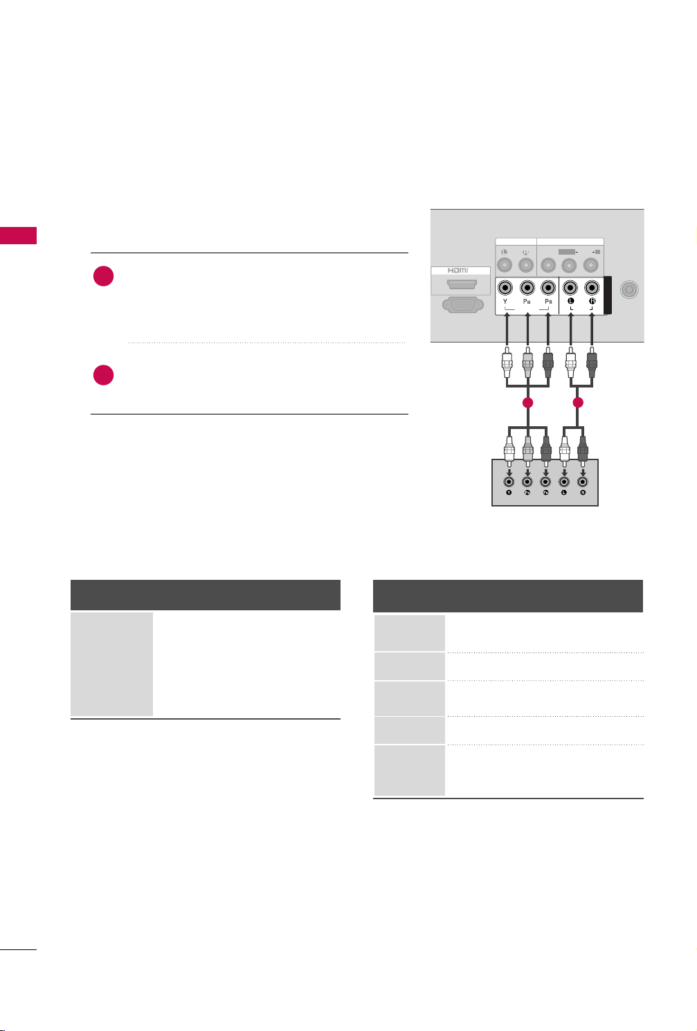
Component Connection
EXTERNAL EQUIPMENT SETUP
1. How to connect
Connect the video outputs (Y, P B, PR
1
top box to the
CCOOMMPPOONNEENNTT IINN VVII DDEEOO
the TV. Match the jack colors (Y = green, P
P
R = red).
Connect the audio output of the digital set-top box to
2
CCOOMMPPOONNEENNTT IINN AAUUDDIIOO
the
)
jacks on the TV.
2. How to use
■
Turn on the digital set-top box.
(
Refer to the owner’s manual for the digital set-top box operation.
■
Select the
IINNPP UUTT
Supported Resolutions
Signal
480i
480p
720 p
10 8 0 i
10 8 0 p
CCoo mmppoonneenntt
input source on the TV using the
button on the remote control.
Component
Yes
Yes
Yes
No
No
HDMI
No
Yes
Yes
No
No
of the digital set-
jacks on
B = blue, and
Y, C
Resolution
720x480i
720x576i
720x480p
)
B/PB
1
R
, CR/P
Horizontal Vertical
Frequency(KHz)Frequency(Hz
15 . 7 3 5 9 . 9 4
15.75 60.00
15.625 50.00
31 . 4 7 5 9 . 9 4
31.50 60.00
2
)
20
720x576p
1280x720p
31.25 50.00
44.96 59.94
45.00 60.00
37.50 50.00
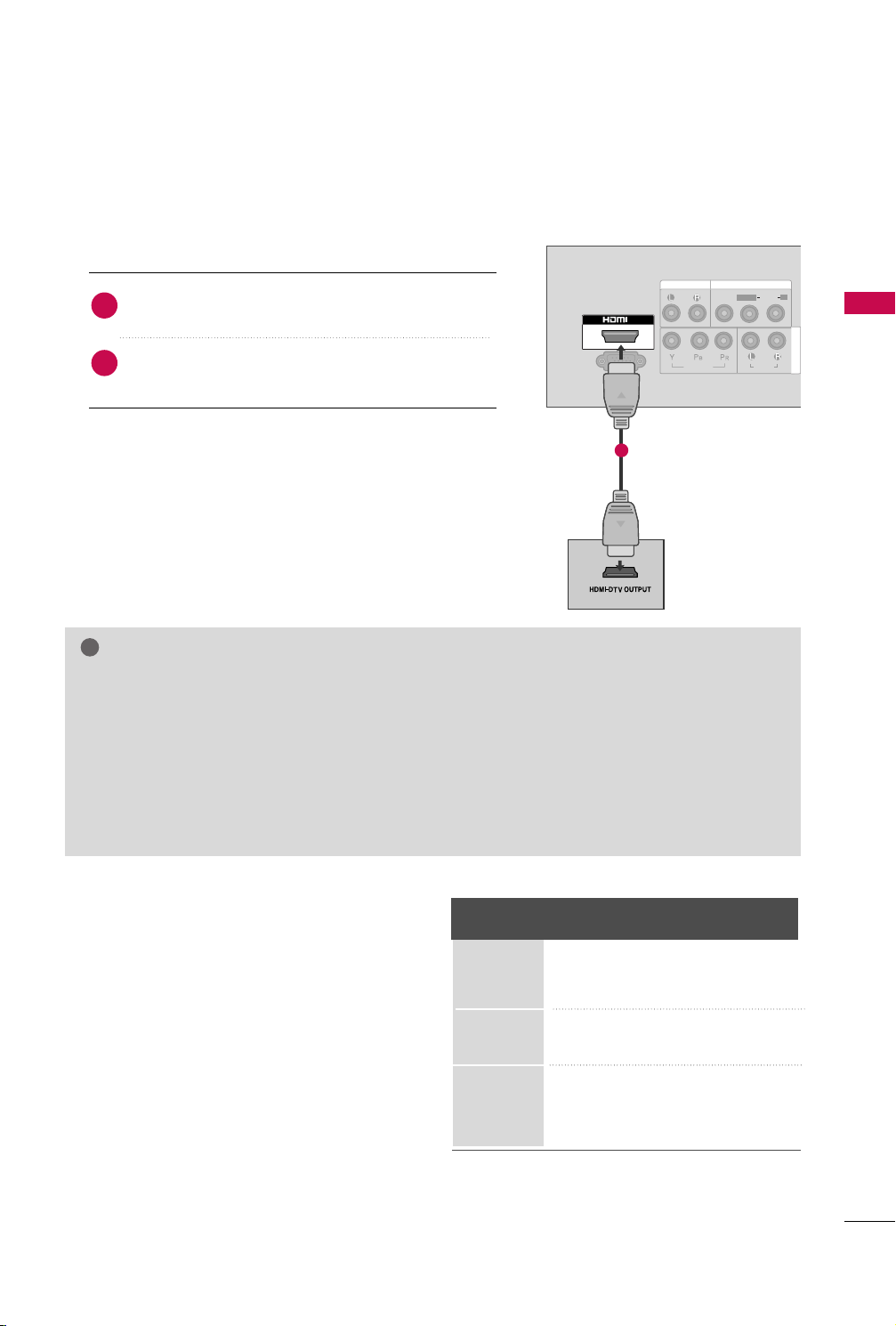
HDMI Connection
!
L/MONO
R
AUDIO
VIDEO
VARIABLE AUDIO OUT
HDMI IN HDMI DVI IN
HDMI/DVI IN
1
IN
SERVICE ONLY
AUDIO OUT
VIDEO
AUDIO
L(MONO)
R
AV IN
AUDIO
VIDEO
COMPONENT IN
1. How to connect
Connect the digital set-top box to the
1
jack on the TV.
No separate audio connection is necessary.
2
HHDDMMII IINN
HDMI supports both audio and video.
2. How to use
■
Turn on the digital set-top box.
(
Refer to the owner’s manual for the digital set-top box.
■
Select the
HHDDMMII
input source on the TV using the
)
IINNPPUUTT
1
button on the remote control.
NOTE
If the DVD player supports Auto HDMI function, the output resolution of the source device will be auto-
GG
matically TV to 1280*720p.
If the DVD player does not support Auto HDMI, you must TV the output resolution appropriately.
GG
To get the best picture quality, adjust the output resolution of the source device to 1280*720p.
We recommend less than 10m for HDMI cable.
GG
HDMI Audio Supported Format: PCM
GG
If the Auto setting is set to Dolby/DTS/Bitstream in some DVDP/STB, make sure to change the setting to
GG
PCM.
If the resolution of external equipment is over 1280*720p, there will be no picture on the TV.
GG
EXTERNAL EQUIPMENT SETUP
HDMI-DTV
Resolution
720x480p
720x576p
1280x720p
Horizontal Vertical
Frequency(kHz) Frequency(Hz)
31 . 4 7 59 . 9 4
31.5 60.00
31.25 50.00
44.96 59.94
45 60.00
37.5 50.00
21
EXTERNAL EQUIPMENT SETUP
IN
SERVICE ONLY
ANTENNA
IN
AUDIO OUT
VIDEO
AUDIO
L(MONO)
R
AV IN
AUDIO
VIDEO
COMPONENT IN
DVD SETUP
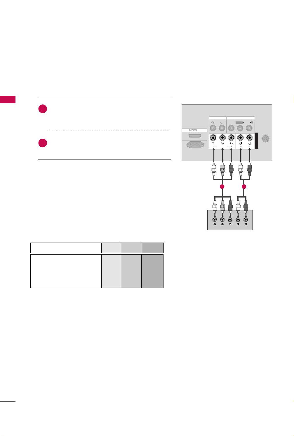
Component Connection
1. How to connect
EXTERNAL EQUIPMENT SETUP
Connect the video outputs (Y, PB, PR
1
2
CCOOMMPPOONNEENNTT IINN VVIIDDEEOO
the
the jack colors (Y = green, P
B = blue, and PR = red
Connect the audio outputs of the DVD to the
CCOOMMPPOONNEENNTT IINN AAUUDDIIOO
2. How to use
■
Turn on the DVD player, insert a DVD.
■
Select the
IINNPP UUTT
■
Refer to the DVD player's manual for operating instructions.
CCoo mmppoonneenntt
input source on the TV using the
button on the remote control.
)
jacks on the TV. Match
jacks on the TV.
of the DVD to
)
.
1 2
Component Input ports
To get better picture quality, connect a DVD player to the
component input ports as shown below.
Component ports on the TV
Video output ports
on DVD player
YPB PR
Y
Y
Y
Y
PB
B-Y
Cb
Pb
R-Y
R
P
Cr
Pr
22
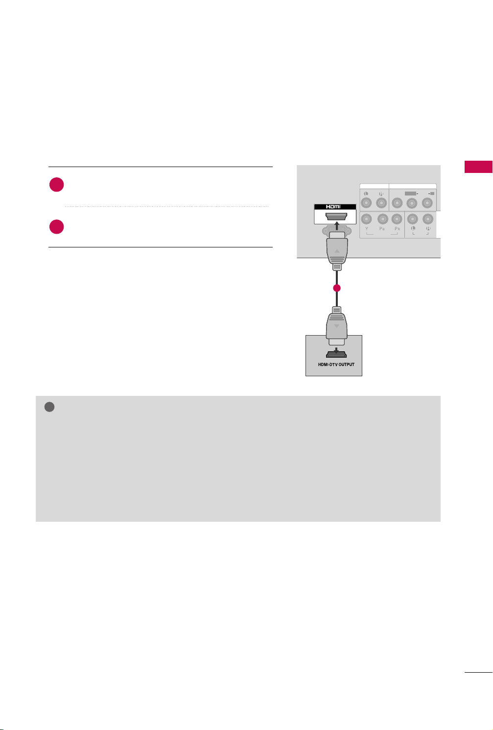
HDMI Connection
L/MONO
R
AUDIO
VIDEO
VARIABLE AUDIO OUT
HDMI IN HDMI DVI IN
HDMI/DVI IN
1
IN
SERVICE ONLY
AUDIO OUT
VIDEO
AUDIO
L(MONO)
R
AV IN
AUDIO
VIDEO
COMPONENT IN
!
1. How to connect
Connect the HDMI output of the DVD to the
1
II NN
jack on the TV.
HHDDMMII
No separated audio connection is necessary.
2
HDMI supports both audio and video.
2. How to use
■
Select the
button on the remote control.
■
Refer to the DVD player's manual for operating instructions.
NOTE
If the DVD player supports Auto HDMI function, the output resolution of the source device will be auto-
GG
matically TV to 1280*720p.
If the DVD player does not support Auto HDMI, you must TV the output resolution appropriately.
GG
To get the best picture quality, adjust the output resolution of the source device to 1280*720p.
We recommend less than 10m for HDMI cable.
GG
HDMI Audio Supported Format: PCM
GG
If the Auto setting is set to Dolby/DTS/Bitstream in some DVDP/STB, make sure to change the setting to
GG
PCM.
If the resolution of external equipment is over 1280*720p, there will be no picture on the TV.
GG
HHDDMMII
input source on the TV using the
IINNPP UU TT
1
EXTERNAL EQUIPMENT SETUP
23
EXTERNAL EQUIPMENT SETUP
!
AV IN 2
IN
ANTENNA
IN
AUDIO OUT
AUDIO
VIDEO
COMPONENT IN
AV IN
L
R
S-VIDEO
VIDEO
OUTPUT
SWITCH
ANT IN
ANT OUT
VIDEO
AUDIO
L(MONO)
R
ANTENNA
IN
DIO
R
IO
COMPONENT IN
OUTPUT
SWITCH
ANT IN
R
S-VIDEO VIDEO
ANT OUT
L
VCR SETUP
■
To avoid picture noise (interference), allow adequate distance between the VCR and TV.
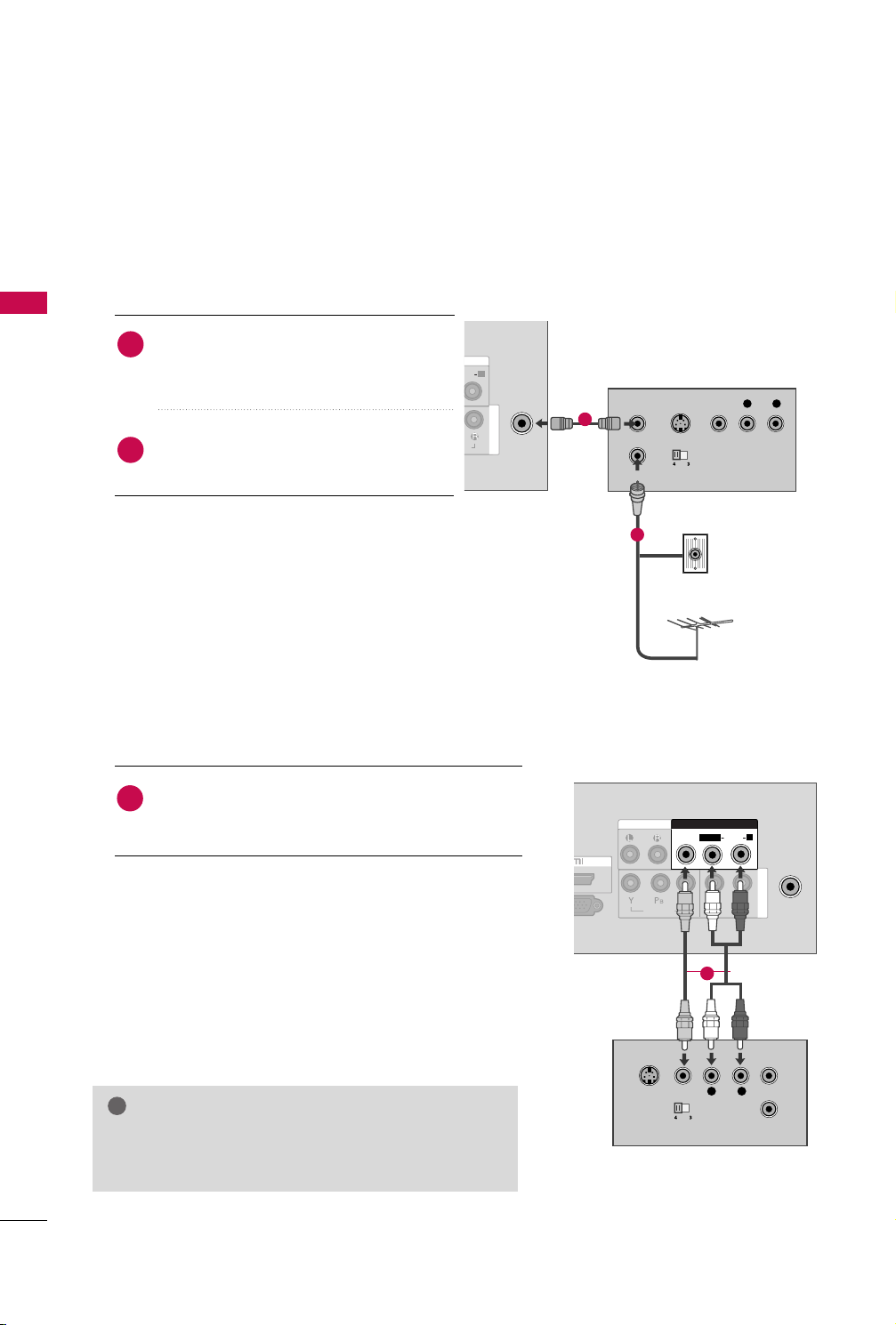
Antenna Connection
1. How to connect
EXTERNAL EQUIPMENT SETUP
Connect the RF antenna out socket of the
1
VCR to the
AANN TTEENN NNAA IINN
socket on the
TV.
Connect the antenna cable to the RF
2
antenna in socket of the VCR.
1
2. How to use
■
Set VCR output switch to 3 or 4 and then tune
TV to the same channel number.
■
Insert a video tape into the VCR and press PLAY
on the VCR. (Refer to the VCR owner’s manual.
Composite (RCA) Connection
1. How to connect
Connect the
1
VCR. Match the jack colors (Video = yellow, Audio Left
= white, and Audio Right = red).
2. How to use
■
Insert a video tape into the VCR and press PLAY on the
VCR. (Refer to the VCR owner’s manual.
■
Select the
button on the remote control.
AAUUDDIIOO/VVIIDDEEOO
AAVV
input source on the TV using the
jacks between TV and
)
)
IINNPP UUTT
2
Wall Jack
Antenna
1
AAUUDDIIOO LL //MMOONN OO
jack of the TV.
NOTE
If you have a mono VCR, connect the audio cable from
GG
the VCR to the
24
OTHER A/V SOURCE SETUP
IN
SERVICE ONLY
ANTENNA
IN
AUDIO OUT
AUDIO
VIDEO
COMPONENT IN
AV IN
L R
VIDEO
VIDEO
AUDIO
L(MONO)
R
L/MONO
R
AUDIO
VIDEO
VARIABLE
AUDIO OUT
IN
SERVICE ONLY
AUDIO
VIDEO
COMPONENT IN
VIDEO
AUDIO
L(MONO)
R
AUDIO OUT
AV IN
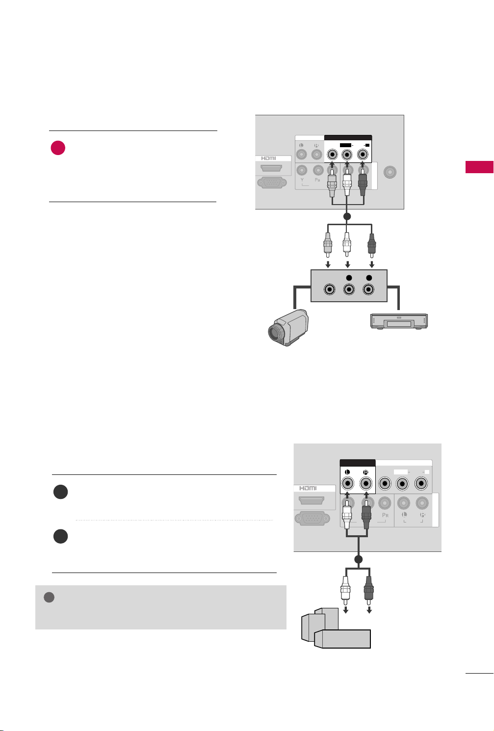
!
1. How to connect
Connect the
1
between TV and external equipment.
Match the jack colors
(
Video = yellow, Audio Left = white, and
Audio Right = red
AAUUDDIIOO/VVIIDDEEOO
.
)
jacks
2. How to use
■
Select the
IINNPP UUTT
■
Operate the corresponding external equipment.
AAVV
input source on the TV using the
button on the remote control.
EXTERNAL STEREO SETUP
EXTERNAL EQUIPMENT SETUP
1
Video Game Set
Camcorder
Use to connected either an external amplifier, or add a subwoofer to your surround sound system.
Connect the input jack of the stereo amplifier to the
1
This function works in following mode : TV, AV, Component, HDMI
GG
AAUUDD IIOO OOUU TT
Set up your speakers through your analog stereo
2
amplifier, according to the instructions provided with
the amplifier.
NOTE
jacks on the TV.
11
25
WATCHING TV / CHANNEL CONTROL
123
456
7809
VOL VOL
CH
CH
ENTER
POWER
MENU Q.VIEW SLEEP
PICTURE SOUND RATIO
MTS
FAVMUTE
A.PROG
MEMORY/ERASE
CAPTION
TV INPUT
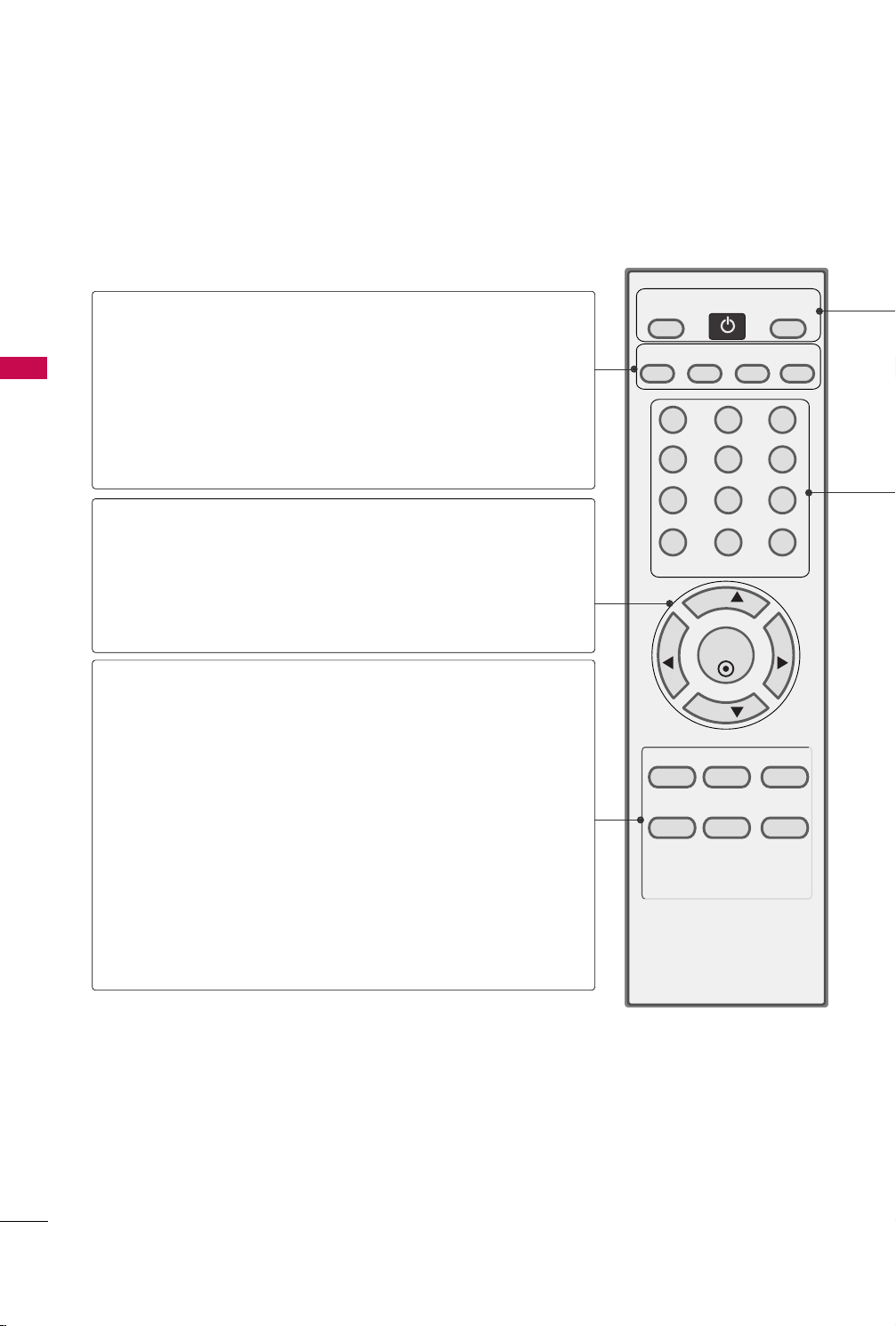
REMOTE CONTROL FUNCTIONS
When using the remote control, aim it at the remote control sensor on the TV.
(AUTO PROGRAM)
A.PROG
WATCHING TV / CHANNEL CONTROL
MEMORY/ERASE
CAPTION
CHANNEL
UP/DOWN
VOLUME UP
/DOWN
THUMBSTICK
(Up/Down/Left
Right/ENTER)
Q.VIEW
MTS
Selects the MTS sound: Mono, Stereo, or SAP.
Searches for available channels.
pp..3300
GG
Memorizes or erases selected channel.
Selects CAPTION mode.
pp..5511
GG
Select available channels.
Increase/decrease the sound level.
Navigate the on-screen menus and adjust the system settings to your preference.
Displays the main menu.
MENU
Tune to the last channel viewed.
Select the amount of time before your TV turns off auto-
SLEEP
matically.
pp..5544
GG
pp..4488
GG
pp..3311
GG
26
PICTURE
SOUND
RATIO
Selects the factory preset picture depend on the viewing
environment.
Selects the factory preset sound for type of program.
Change the aspect ratio.
pp..3366
GG
pp..44 33
GG
pp..3355
GG
POWER
TV
Turns your TV.
In AV, Component and HDMI input sources, screen returns to the last TV channel.
INPUT
Select the desired input source.
NUMBER button
MUTE
Switch the sound on or off.
FAV
Scroll through the programmed Favorite channels.
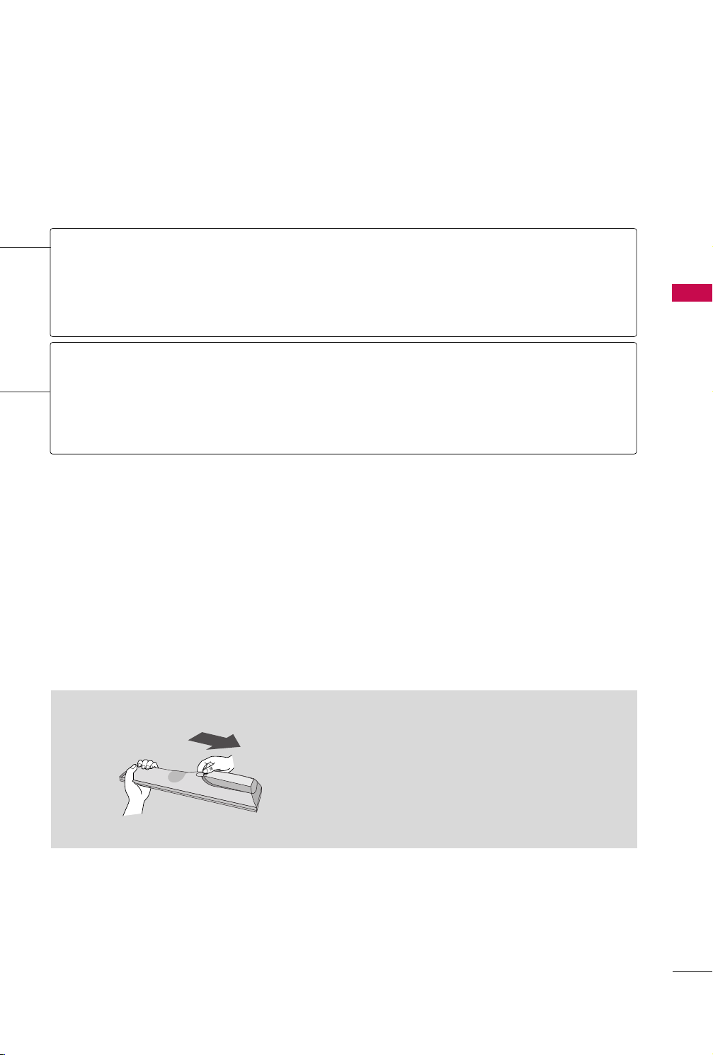
Installing Batteries
pp..3333
GG
■
Open the battery compartment cover on the back
side and install the batteries matching correct
polarity (+ with +, - with -).
■
Install two 1.5V AAA batteries. Don’t mix old or
used batteries with new ones.
■
Close cover.
WATCHING TV / CHANNEL CONTROL
27
WATCHING TV / CHANNEL CONTROL
!
TURNING ON THE TV
First, connect power cord correctly.
1
At this moment, the TV switches to standby mode.
■
In standby mode to turn TV on, press the button on the TV or press the
remote control.
PP OO WWEE RR
button on the
WATCHING TV / CHANNEL CONTROL
Select the viewing source by using the
2
■
This TV is programmed to remember which power state it was last set to, even if the power cord is out.
When finished using the TV, press the
3
mode.
IINNPP UUTT
PP OO WWEE RR
button on the remote control.
button on the remote control. The TV reverts to standby
NOTE
GG
If you intend to be away on vacation, disconnect the power plug from the wall power outlet.
GG
If you do not complete the
sseetttt iinngg
IInniittiiaalliizziinngg sseettuu pp
If the OSD (On Screen Display) is displayed on the screen after turning on the TV, you can adjust the
LLaann gguu aaggee, AAuu ttoo TTuu nniinngg
Note:
It will automatically disappear after approx. 40 seconds unless a button is pressed.
procedure is completed.
IInniittiiaall sseettttiinngg
.
, it will appear whenever the TV is switched on until the
CHANNEL SELECTION
IInniittii aall
1
Press the
CCHH ((
DD
or
EE
))
or
NNUUMMBBEERR
buttons to select a channel number.
VOLUME ADJUSTMENT
Adjust the volume to suit your personal preference.
FF
))
button to adjust the volume.
or
GG
MMUUTTEE
MMUUTTEE
button.
or
VVOOLL ((
FF
or
))
GG
Press the
1
If you want to switch the sound off, press the
2
You can cancel the Mute function by pressing the
3
button.
VVOOLL ((
28
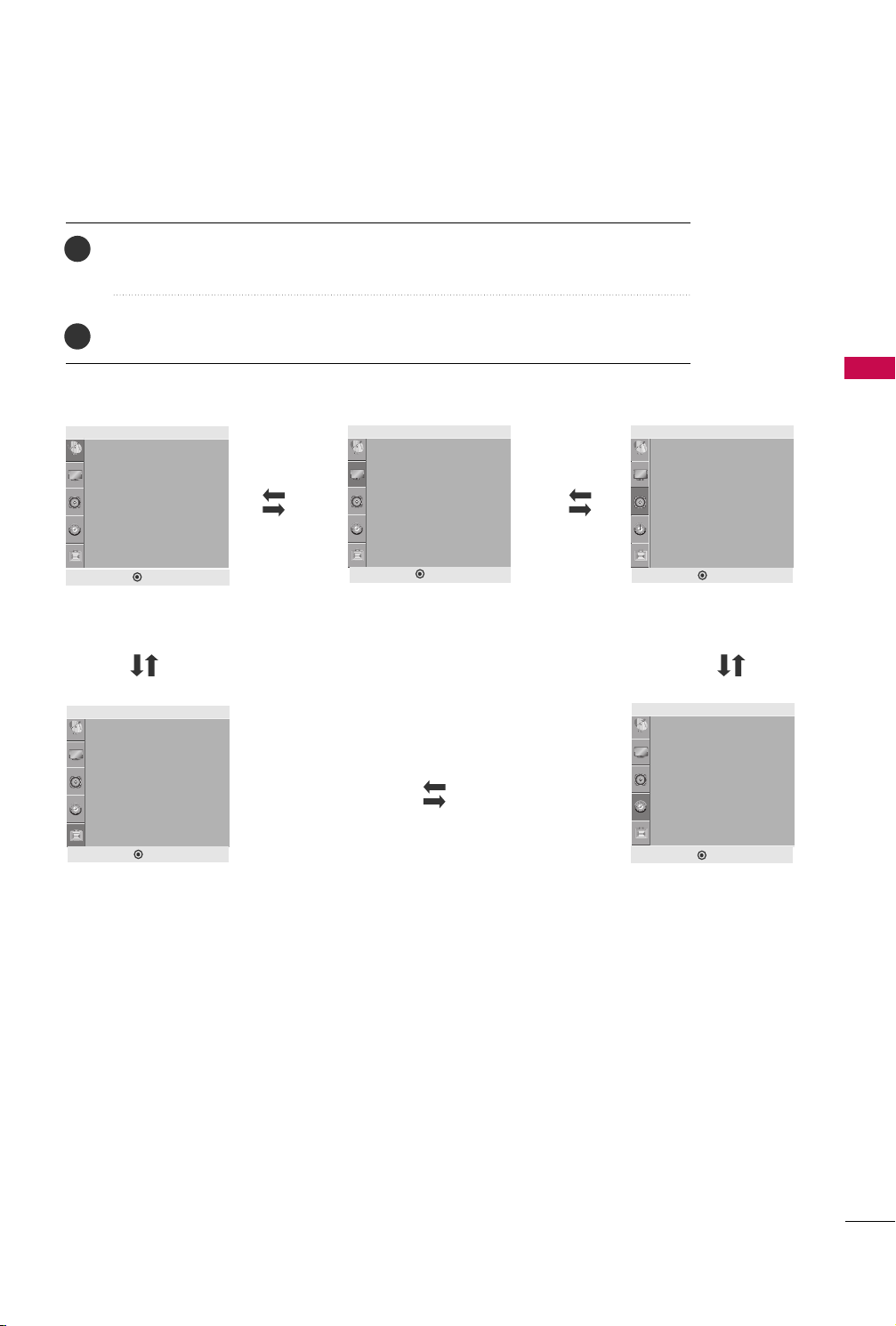
ON-SCREEN MENUS SELECTION
1
Press the
Press the
2
Setup
Auto Tuning
Manual Tuning
Favorite Channel
DEF G MENU
Setup MENU
Option
Language
Key Lock
Caption/Text
Power Indicator
Factory Reset
MMEENNUU
button and then use
button and then use
GG
or
DD
DD EE FF GG
Picture
Aspect Ratio
Picture Mode
• Backlight 100
• Contrast 100
• Brightness 50
• Sharpness 70
• Color 70
• Tint 0
DEF G MENU
Picture MENU
button to select the each menu.
EE
button to display the available menus.
E
Audio
Sound Mode
• Treble 50
• Bass 50
• Reset
Auto Volume
Balance 0
DEF G MENU
Audio MENU
Time
Clock
Off Time
On Time
Sleep Timer
WATCHING TV / CHANNEL CONTROL
DEF G MENU
Option MENU
DEF G MENU
Time MENU
29
WATCHING TV / CHANNEL CONTROL
CHANNEL SEARCH
Auto Tuning: Program Search
Auto Tuning should be used to memorize all the active channels in
your area before you are able to use the TV.
There are two ways of storing channels in the TV's memory. You
can use either.
WATCHING TV / CHANNEL CONTROL
One is called AUTO TUNING and the other is called MANUAL
TUNING.
In AUTO TUNING mode, the TV will memorize the channels in
ascending numerical order. If there are additional channels you
want to add or delete, you can manually add or delete those
channels with Manual Tuning.
- Redo Auto Tuning if the TV is ever moved to another location.
- Auto Tuning will search for channels only through the Antenna
jack.
- If channels numbers for broadcast over-the air TV and cable TV
are duplicated where different channels have the same number,
press the same number buttons again to toggle between:
Broadcast TV Channels
Cable TV Channels
(For example, press 17 to go to the channel, press 17 again to go
to the duplicated channel.)
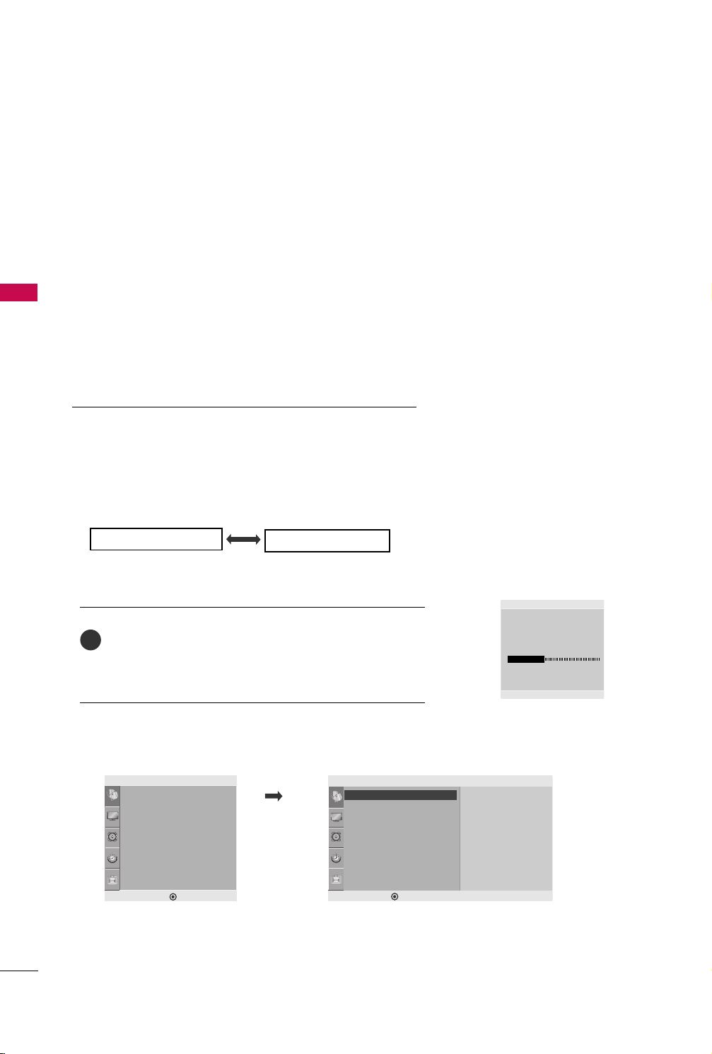
Press the
1
nel search. If you want to stop auto tuning, press the
AA..PPRR OO GG
AAUUTTOO TTUUNNIINN GG
button.
starts the chan-
MMEENNUU
button. Only the channels found up to at that time are memorized.
■
You can also use the
Setup
Auto Tuning
Manual Tuning
Favorite Channel
DE F G
MENU
SS eettuupp
menu to adjust
AAuu ttoo TTuu nniinngg
Setup
Auto Tuning G
Auto Tuning
Manual Tuning
Favorite Channel
DE F G
.
MENU
To Start
Auto Tuning
CATV
34
MENU Stop
49%
30
 Loading...