

Page 1
Internal Use Only
North/Latin America http://aic.lgservice.com
Europe/Africa http://eic.lgservice.com
Asia/Oceania http://biz.lgservice.com
COLOR MONITOR
SERVICE MANUAL
CHASSIS NO. : LM14B
MODEL: 24M35H
CAUTION
BEFORE SERVICING THE UNIT,
READ THE SAFETY PRECAUTIONS IN THIS MANUAL.
P/NO : MFL67715246 (1311-REV00) Printed in China
Page 2

CONTENTS
CONTENTS .............................................................................................. 2
PRECAUTION............................................................................................3
SERVICING PRECAUTIONS.....................................................................4
SPECIFICATIONS......................................................................................6
TIMING CHART .......................................................................................11
ADJUSTMENT .........................................................................................14
BLOCK DIAGRAM...................................................................................18
TROUBLE SHOOTING ............................................................................19
EXPLODED VIEW .................................................................................. 22
SVC. SHEET ...............................................................................................
Copyright © 2010 LG Electronics. Inc. All right reserved.
Only for training and service purposes
- 2 -
LGE Internal Use Only
Page 3
PRECAUTION
WARNING FOR THE SAFETY-RELATED COMPONENT.
• There are some special components used in LCD monitor that
are important for safety. These parts are marked on the
schematic diagram and the Exploded View. It is essential
that these critical parts should be replaced with the
manufacturer’s specified parts to prevent electric shock, fire or
other hazard.
• Do not modify original design without obtaining written
permission from manufacturer or you will void the original parts
and labor guarantee.
TAKE CARE DURING HANDLING THE LCD MODULE WITH
BACKLIGHT UNIT.
• Must mount the module using mounting holes arranged in four
corners.
• Do not press on the panel, edge of the frame strongly or electric
shock as this will result in damage to the screen.
• Do not scratch or press on the panel with any sharp objects,
such as pencil or pen as this may result in damage to the panel.
• Protect the module from the ESD as it may damage the
electronic circuit (C-MOS).
WARNING
BE CAREFUL ELECTRIC SHOCK !
• If you want to replace with the new backlight (CCFL) or LIPS
part, must disconnect the AC power because high voltage
appears at inverter circuit about 650Vrms.
• Handle with care wires or connectors of the inverter circuit. If
the wires are pressed cause short and may burn or take fire.
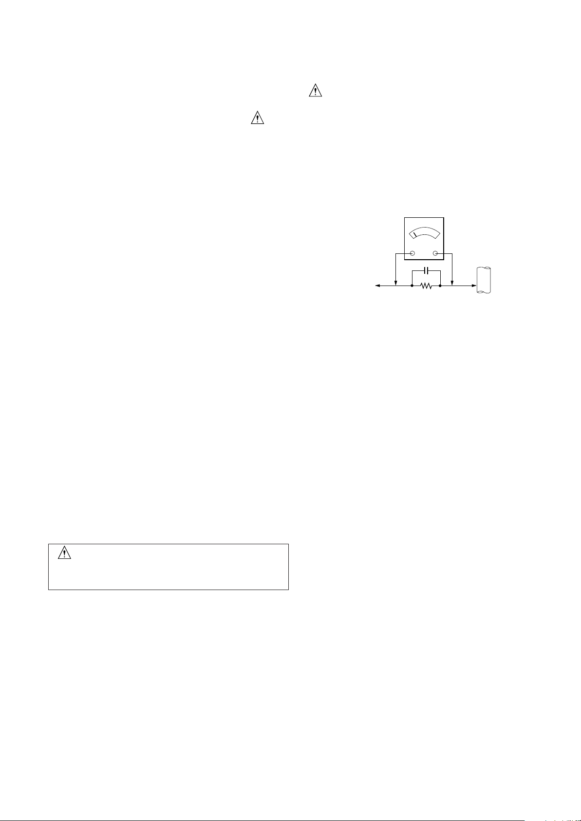
Leakage Current Hot Check Circuit
AC Volt-meter
Good Earth Ground
such as WATER PIPE,
To Instrument's
exposed
METALLIC PARTS
When 25A is impressed between Earth and 2nd Ground
for 1 second, Resistance must be less than 0.1
*Base on Adjustment standard
0.15uF
1.5 Kohm/10W
CONDUIT etc.
Ω
• Make certain that treatment person’s body are grounded
through wrist band.
• Do not leave the module in high temperature and in areas of
high humidity for a long time.
• The module not be exposed to the direct sunlight.
• Avoid contact with water as it may a short circuit within the
module.
• If the surface of panel become dirty, please wipe it off with a
softmaterial. (Cleaning with a dirty or rough cloth may damage
the panel.)
CAUTION
Please use only a plastic screwdriver to protect yourself
from shock hazard during service operation.
Copyright © 2010 LG Electronics. Inc. All right reserved.
Only for training and service purposes
- 3 -
LGE Internal Use Only
Page 4

SERVICING PRECAUTIONS
CAUTION: Before servicing receivers covered by this service
manual and its supplements and addenda, read and follow the
SAFETY PRECAUTIONS on page 3 of this publication.
NOTE: If unforeseen circumstances create conflict between the
following servicing precautions and any of the safety precautions on
page 3 of this publication, always follow the safety precautions.
Remember: Safety First.
General Servicing Precautions
1. Always unplug the receiver AC power cord from the AC power
source before;
a. Removing or reinstalling any component, circuit board
module or any other receiver assembly.
b. Disconnecting or re-connecting any receiver electrical plug or
other electrical connection.
c. Connecting a test substitute in parallel with an electrolytic
capacitor in the receiver.
CAUTION: A wrong part substitution or incorrect polarity
installation of electrolytic capacitors may result in an
explosion hazard.
2. Test high voltage only by measuring it with an appropriate high
voltage meter or other voltage measuring device (DVM,
FETVOM, etc) equipped with a suitable high voltage probe.
Do not test high voltage by "drawing an arc".
3. Do not spray chemicals on or near this receiver or any of its
assemblies.
4. Unless specified otherwise in this service manual, clean
electrical contacts only by applying the following mixture to the
contacts with a pipe cleaner, cotton-tipped stick or comparable
non-abrasive applicator; 10% (by volume) Acetone and 90% (by
volume) is opropyl alcohol (90%-99% strength)
CAUTION: This is a flammable mixture.
Unless specified otherwise in this service manual, lubrication of
contacts in not required.
5. Do not defeat any plug/socket B+ voltage interlocks with which
receivers covered by this service manual might be equipped.
6. Do not apply AC power to this instrument and/or any of its
electrical assemblies unless all solid-state device heat sinks are
correctly installed.
7. Always connect the test receiver ground lead to the receiver
chassis ground before connecting the test receiver positive
lead.
Always remove the test receiver ground lead last.
8. Use with this receiver only the test fixtures specified in this
service manual.
CAUTION: Do not connect the test fixture ground strap to any
heat sink in this receiver.
Electrostatically Sensitive (ES) Devices
Some semiconductor (solid-state) devices can be damaged easily
by static electricity. Such components commonly are called
Electrostatically Sensitive (ES) Devices. Examples of typical ES
devices are integrated circuits and some field-effect transistors and
semiconductor "chip" components. The following techniques
should be used to help reduce the incidence of component
damage caused by static by static electricity.
1. Immediately before handling any semiconductor component or
semiconductor-equipped assembly, drain off any electrostatic
charge on your body by touching a known earth ground.
Alternatively, obtain and wear a commercially available
discharging wrist strap device, which should be removed to
prevent potential shock reasons prior to applying power to the
unit under test.
Copyright © 2010 LG Electronics. Inc. All right reserved.
Only for training and service purposes
2. After removing an electrical assembly equipped with ES
devices, place the assembly on a conductive surface such as
aluminum foil, to prevent electrostatic charge buildup or
exposure of the assembly.
3. Use only a grounded-tip soldering iron to solder or unsolder ES
devices.
4. Use only an anti-static type solder removal device. Some solder
removal devices not classified as "anti-static" can generate
electrical charges sufficient to damage ES devices.
5. Do not use freon-propelled chemicals. These can generate
electrical charges sufficient to damage ES devices.
6. Do not remove a replacement ES device from its protective
package until immediately before you are ready to install it.
(Most replacement ES devices are packaged with leads
electrically shorted together by conductive foam, aluminum foil
or comparable conductive material).
7. Immediately before removing the protective material from the
leads of a replacement ES device, touch the protective material
to the chassis or circuit assembly into which the device will be
installed.
CAUTION: Be sure no power is applied to the chassis or circuit,
and observe all other safety precautions.
8. Minimize bodily motions when handling unpackaged
replacement ES devices. (Otherwise harmless motion such as
the brushing together of your clothes fabric or the lifting of your
foot from a carpeted floor can generate static electricity
sufficient to damage an ES device.)
General Soldering Guidelines
1. Use a grounded-tip, low-wattage soldering iron and appropriate
tip size and shape that will maintain tip temperature within the
range or 500ºF to 600ºF.
2. Use an appropriate gauge of RMA resin-core solder composed
of 60 parts tin/40 parts lead.
3. Keep the soldering iron tip clean and well tinned.
4. Thoroughly clean the surfaces to be soldered. Use a mall wirebristle (0.5 inch, or 1.25cm) brush with a metal handle.
Do not use freon-propelled spray-on cleaners.
5. Use the following unsoldering technique
a. Allow the soldering iron tip to reach normal temperature.
(500ºF to 600ºF)
b. Heat the component lead until the solder melts.
c. Quickly draw the melted solder with an anti-static, suction-
type solder removal device or with solder braid.
CAUTION: Work quickly to avoid overheating the circuit
board printed foil.
6. Use the following soldering technique.
a. Allow the soldering iron tip to reach a normal temperature
(500ºF to 600ºF)
b. First, hold the soldering iron tip and solder the strand against
the component lead until the solder melts.
c. Quickly move the soldering iron tip to the junction of the
component lead and the printed circuit foil, and hold it there
only until the solder flows onto and around both the
component lead and the foil.
CAUTION: Work quickly to avoid overheating the circuit
board printed foil.
d. Closely inspect the solder area and remove any excess or
splashed solder with a small wire-bristle brush.
- 4 -
LGE Internal Use Only
Page 5

IC Remove/Replacement
Some chassis circuit boards have slotted holes (oblong) through
which the IC leads are inserted and then bent flat against the
circuit foil. When holes are the slotted type, the following technique
should be used to remove and replace the IC. When working with
boards using the familiar round hole, use the standard technique
as outlined in paragraphs 5 and 6 above.
Removal
1. Desolder and straighten each IC lead in one operation by gently
prying up on the lead with the soldering iron tip as the solder
melts.
2. Draw away the melted solder with an anti-static suction-type
solder removal device (or with solder braid) before removing the
IC.
Replacement
1. Carefully insert the replacement IC in the circuit board.
2. Carefully bend each IC lead against the circuit foil pad and
solder it.
3. Clean the soldered areas with a small wire-bristle brush.
(It is not necessary to reapply acrylic coating to the areas).
"Small-Signal" Discrete TransistorRemoval/Replacement
1. Remove the defective transistor by clipping its leads as close as
possible to the component body.
2. Bend into a "U" shape the end of each of three leads remaining
on the circuit board.
3. Bend into a "U" shape the replacement transistor leads.
4. Connect the replacement transistor leads to the corresponding
leads extending from the circuit board and crimp the "U" with
long nose pliers to insure metal to metal contact then solder
each connection.
Power Output, Transistor Device
Removal/Replacement
1. Heat and remove all solder from around the transistor leads.
2. Remove the heat sink mounting screw (if so equipped).
3. Carefully remove the transistor from the heat sink of the circuit
board.
4. Insert new transistor in the circuit board.
5. Solder each transistor lead, and clip off excess lead.
6. Replace heat sink.
Circuit Board Foil Repair
Excessive heat applied to the copper foil of any printed circuit
board will weaken the adhesive that bonds the foil to the circuit
board causing the foil to separate from or "lift-off" the board. The
following guidelines and procedures should be followed whenever
this condition is encountered.
At IC Connections
To repair a defective copper pattern at IC connections use the
following procedure to install a jumper wire on the copper pattern
side of the circuit board. (Use this technique only on IC
connections).
1. Carefully remove the damaged copper pattern with a sharp
knife. (Remove only as much copper as absolutely necessary).
2. carefully scratch away the solder resist and acrylic coating (if
used) from the end of the remaining copper pattern.
3. Bend a small "U" in one end of a small gauge jumper wire and
carefully crimp it around the IC pin. Solder the IC connection.
4. Route the jumper wire along the path of the out-away copper
pattern and let it overlap the previously scraped end of the good
copper pattern. Solder the overlapped area and clip off any
excess jumper wire.
At Other Connections
Use the following technique to repair the defective copper pattern
at connections other than IC Pins. This technique involves the
installation of a jumper wire on the component side of the circuit
board.
1. Remove the defective copper pattern with a sharp knife.
Remove at least 1/4 inch of copper, to ensure that a hazardous
condition will not exist if the jumper wire opens.
2. Trace along the copper pattern from both sides of the pattern
break and locate the nearest component that is directly
connected to the affected copper pattern.
3. Connect insulated 20-gauge jumper wire from the lead of the
nearest component on one side of the pattern break to the lead
of the nearest component on the other side.
Carefully crimp and solder the connections.
CAUTION: Be sure the insulated jumper wire is dressed so the
it does not touch components or sharp edges.
Diode Removal/Replacement
1. Remove defective diode by clipping its leads as close as
possible to diode body.
2. Bend the two remaining leads perpendicular y to the circuit
board.
3. Observing diode polarity, wrap each lead of the new diode
around the corresponding lead on the circuit board.
4. Securely crimp each connection and solder it.
5. Inspect (on the circuit board copper side) the solder joints of
the two "original" leads. If they are not shiny, reheat them and if
necessary, apply additional solder.
Fuse and Conventional Resistor
Removal/Replacement
1. Clip each fuse or resistor lead at top of the circuit board hollow
stake.
2. Securely crimp the leads of replacement component around
notch at stake top.
3. Solder the connections.
CAUTION: Maintain original spacing between the replaced
component and adjacent components and the circuit board to
prevent excessive component temperatures.
Copyright © 2010 LG Electronics. Inc. All right reserved.
Only for training and service purposes
- 5 -
LGE Internal Use Only
Page 6
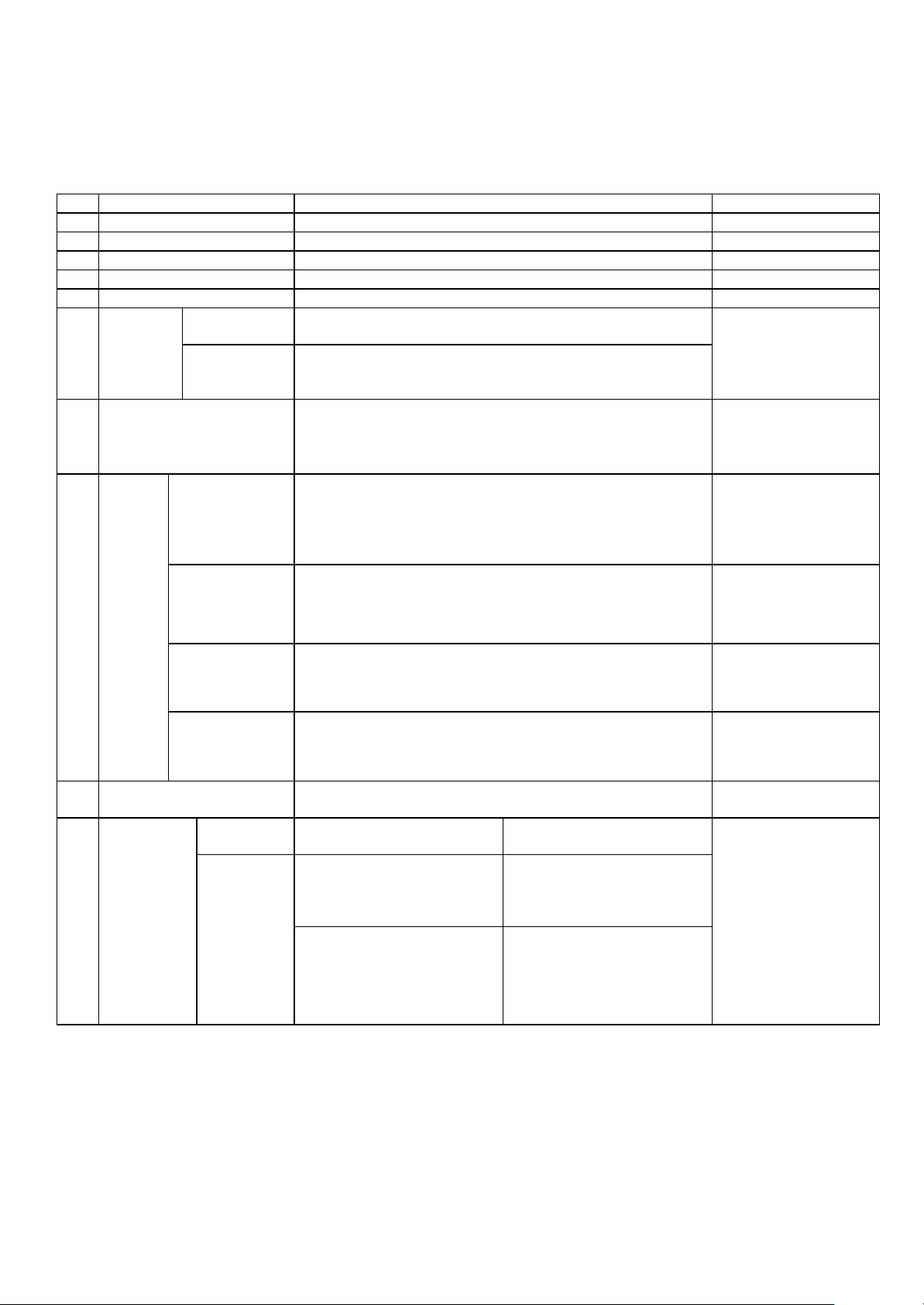
SPECIFICATIONS
1. General Specification
No Item
1 Customer BRAND
2 User Model Name 24M35
3 Sale region Refer to Suffix standard
4 Feature 23.6” Wide LCD MONITOR
5 Chassis Name LM14B
General External SW
Scope &Adj.
6
7
Power Cord
Signal Cable
(D-SUB)
Function OSD,DDC2B,DDC2AB, HDCP, Control Lock,
MENU,READER,FUNC,AUTO,INPUT/EXIT, POWER
Original Ratio / Wid
e, black level, Super Energy Saving, Picture mode
Length : 1.5±0.05 M
Shape : Wall-out
Color : Black
Length : 1.5m
Shape : Detachable Type
Color : Black
Pin : Triple Row, 15 Pin D-Sub
Content Remark
Refer to Suffix
standard and power
cord table
Refer to BOM
Length : 1.5m
DVI Do not Support
8 Cable
Audio Length : ,Shape : ,Color: ,Pin
TV Length : ,Shape : ,Color: ,Pin
9 Power Refer to BOM
P/No Specification
10
Applying
module list
Panel biz
Shape : Detachable Type
Color : Black
Pin : Triple Row, 18-Position DVI-D
Adapter
- Wall Mount Type
CMI(LGM236AC32)
CMI:EAJ62131901
BLU:EBV60978023
BOE(LGM236AB32)
BOE:EAJ62072001/2
BLU:EBV60978022
M236HGE-P02
LM23030023B
HM236WU3-100
LM23030023A
Do not Support
Do not Support
Copyright © 2010 LG Electronics. Inc. All right reserved.
Only for training and service purposes
- 6 -
LGE Internal Use Only
Page 7
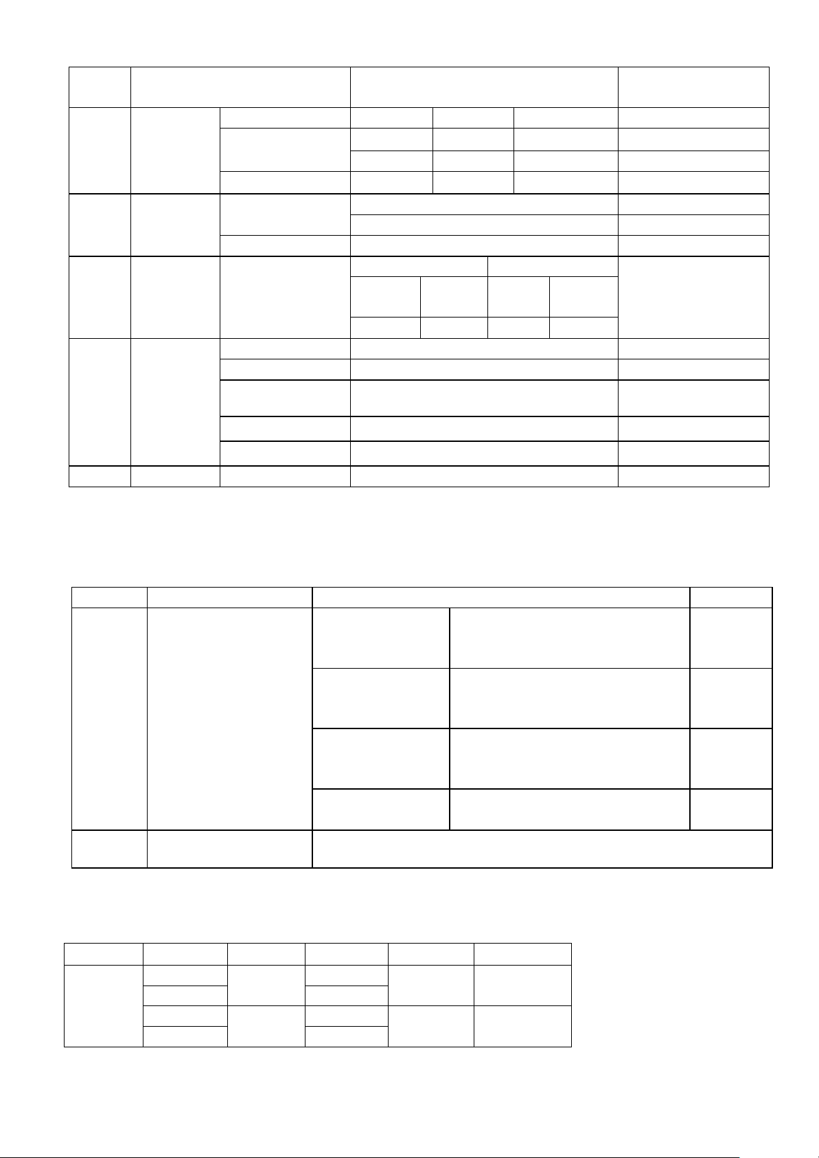
2. Mechanical specification
No
1
2
3
Product
Dimension
Product
Weight
Container
Loading
Quantity
4 Stand
Assy
Item Content Remark
Before Packing
Width (W) Length (D) Height (H)
55.6
21.5
43.8
With stand
55.6 9.8 34.1 Without stand
After Packing
Only SET
With BOX
Individual or
Palletizing
62.5
41.4
4.24kg
20ft 40ft
Individual Palletizi
ng
14.5
3.0kg With stand
2.7kg
Individu
al
Palletizin
g
Without stand
816 630 1664 1400
Type Base detachable
Size (W x D x H) 25.0*21.5*3.1
Tilt Degree
-3°(+/-3°)~ +20°(+5°/-0°)
Tilt force 0.8~1.3kgf
Folding Degree None
5 Appearance General Refer to Standard of LG(56)G2-1011
** C/A + B/C GAP: 0.5mm (Design gap)
3. Optical Character
3.1 Normal Mode
No Item Criteria Remark
1
2
Luminance(휘도)
Light Leakage Condition: Do not visible at 300 Lux
Average
Luminance
(cd/m
2
)
Average
Luminance
(cd/m )
2
Average
Luminance
(cd/m )
2
Luminance
Uniformity
120 (min)
(Full
white pattern, 0.7V)
150(min),200 (Typ.)
(Full white pattern, 0.7V)
120(min)
(Full white pattern, 0.7V)
75%(min),
Medium
Warm
Brightness:100
Contrast:100
Cool
3.2 Reader Mode
Pattern Coordinate
Wx 0.365
White
Wy 0.360
Wx 0.353
Wy 0.367
Copyright © 2010 LG Electronics. Inc. All right reserved.
Only for training and service purposes
Minimum Normal Maximum
Typ-0.030 Typ+0.030
Typ-0.030 Typ+0.030
- 7 -
Reader 1
Reader 2
LGE Internal Use Only
Page 8
4. Engineering Specification
1
2 Operating Frequency
3 Resolution
4 Power Voltage
5 Inrush Current Cold Start : 50 A Hot : 120 A
6
7
8
Supported Sync. Type
Separate Sync.Digital
Analog
HDMI
Analog
HDMI
Horizontal 30 ∼ 83kHz
Vertical 56 ∼ 75 Hz
Horizontal 30 ∼ 83kHz
Vertical 56~61HZ
Max. 1920×1080 @ 60Hz
Recommend 1920×1080 @ 60Hz
Input :100 – 240 Vac, 50 or 60Hz, 1.0A
Output:19V 1.2A
Operating Condition
Sync
(H/V)
Video LED Wattage
On Mode
(ENERGY STAR
On/On Active White 19W(Max)
@standard)
On Mode On/On Active White
Sleep Mode
Off Mode
(Power switch off)
Off/On
On/Off
Off
Off/Off
- - Off < 0.3W
White
Blinking
Super Energys Saving Low/High/Off On White
MTBF 30,000 HRS with 90%
Confidence level
Lamp Life : 30,000 Hours(Min)
25W (typ)
29W(max)
< 0.3W
Efficiency up to:
Low:15%±5%(≥2W)
High:25%±5%(≥4W)
Using Altitude 5,000 m (for Reliability) 3,000m(for FOS)
Test condition
EPA6.0 Metho
d
Refer to P51
Test condition
1. 1920x1080
@60Hz
2. burst patter
3. 100~240V
4. After aging
30min
-Test Condition
(1)
n
Copyright © 2010 LG Electronics. Inc. All right reserved.
Only for training and service purposes
- 8 -
LGE Internal Use Only
Page 9

9 Environme 0perating Temperature
nt
Condition
Storage Temperature
Humidity 10% ~ 80%
Humidity 5% ~ 90% non-condensing
BRIGHTNESS 0 ~ 100
COLOR TEMP
ORIGINAL RA
TIO
MENU
(Monitor b
lock)
BLACK LEVE BLACK LEVEL enabl
L e at HDMI input
10 °C ~ 35 °C
-20 °C ~ 60 °C
WARM
PRESET MEDIUM
COOL
RED
USER GREEN
BLUE
WIDE
ORIGINAL
▶ HIGH / LOW
OSD
MENU
MENU
(AV/TV bl
ock)
LANGUAGE ▶ ENGLISH
17 Language:
English, Germanic, F
rench, Spanish, Italia
n, Swedish, Finnish,
Portuguese Brazilian
Portuguese, Polish,
Russian, Greek, Chi
nese, Japanese, Kor
FACTORY RE
SET
▶ NO( /YES )
ean, Ukrainian
Hindi
CHANNEL
2~69(AIR) / 1 ~ 125(CABLE)
ADD/DEL CH ADD/DELETE
CHANNEL No Support:
AUTO CHANNEL ON/OFF
SELECT AIR/C
ABLE
FINE TUNE 0 ~ 100
CONTRAST 0~100
BRIGHTNESS 0~100
ADJUSTMENT SHARPNESS 0~100 No Support:
COLOR 0~100
TINT 0~100
AUDIO No Support:
VOLUME 0~100
BASS 0~100
TREBLE
0~100
SETUP
Copyright © 2010 LG Electronics. Inc. All right reserved.
Only for training and service purposes
MUTE ON/OFF
SOUND
MONO/STEREO
LANGUAGE▶ English/German/French/Espe
ranto
Italian/Korean…
IMAGE SIZE ▶ FULL/1:1
OSD POSITION
TRANSPARENCY 0~100
- 9 -
No Support:
LGE Internal Use Only
Page 10

5. Applying module Character
Maker BOE
Type TFT
Active Display Area 521.28 (H)x293.22(V)
Pixel Pitch [mm] 0.2715(H)mm x 0.2715(V)mm.
LCD Module
1
Feature
Viewing Angle
2
<CR≥10>
Contrast Ratio(명암 비)
3
Electrical Interface 2ch-LVDS
Color Depth 16.7M colors
Size (Outline) [mm] 545.1 (W) x 320.5(H) x7.1(T) (Typ.)
Surface Treatment
Operating Mode TN mode, normally White
Back light Unit White LED
Haze 25%,3H hard coating
Horizontal(R/L) : +45º/-45º ( (Typ.)
Vertical(Top/Bottom) : +20º/-45º (Typ.)
700(MIN), 1000(TYP), DFC->5,000,000:1(Typ.)
4
5
Response Time On/off:5ms(TYP),
W
White
X
Minimum Normal Maximum
Typ-0.030
WY 0.329
W
WY
W
WY
R
X
RY
G
X
GY
B
X
BY
X
Typ-0.030
X
Typ-0.030
Typ-0.03
CIE Color
Coordinates
(색 좌표)
White
White
Red
Green
Blue
0.313
0.302
0.311
0.283
0.298
0.643
0.342
0.317
0.628
0.148
0.064
Typ+0.030
Typ+0.030
Typ+0.030
Typ-0.03
Warm
(6500K)
Medium
(8000K)
Cool
(9300K)
Warm
(6500K)
5.1 Display Area
1) Active Display Area of the LCD Monitor Should be within Cabinet’s Bezel.
2) Distance Difference between Active Area and Bezel
| A-B|<1.0 mm , | C-D|<1.0 mm
A: The Distance from The Left of Active Area to the Bezel
B: The Distance from The Right of Active Area to the Bezel
C: The Distance from The Top of Active Area to the Bezel
D: The Distance from The Bottom of Active Area to the Bezel
Copyright © 2010 LG Electronics. Inc. All right reserved.
Only for training and service purposes
- 10 -
C
Active area
A
A A B
Bezel
D
LGE Internal Use Only
Page 11

6. EDID
6.1 24M35H
No Item Content
1 Manufacturer ID GSM 1E 6D
2 Product ID
3 Year 2013 17
4 Version 1 01
5 Revision Analog : 03 03
6 Serial Number
7 Week
8 Model Name
9 Check Sum
10 Special Item Need to Input Serial Number
* Protocol : DDC 2AB
Data ( 128 Bytes ) --Æ24M35H
EDID Ver. 1.3 FOR ANALOG ( 128Byte)
(Analog) 23118 5A4E
(HDMI) 23120 5A50
* *
** **
24M35
**** ****
16진 Data
--
EDID Ver. 1.3 FOR HDMI ( 256Byte)
Copyright © 2010 LG Electronics. Inc. All right reserved.
Only for training and service purposes
- 11 -
LGE Internal Use Only
Page 12

(1) Signal(Video & Sync)
Video
Sync
TIMING CHART
C
B
(2) H/V Timing
CLASSIF
MODE
ICATION
H(Pixels) -
1
V(Lines) + 70.08 449 400 12 2 35
H(Pixels) -
2
V(Lines) - 59.94 525 480 10 2 33
H(Pixels) -
3
V(Lines) - 75 500 480 1 3 16
H(Pixels) +
4
V(Lines) + 60.317 628 600 1 4 23
H(Pixels) +
5
V(Lines) + 75.0 625 600 1 3 21
H(Pixels) -
6
V(Lines) - 60.0 806 768 3 6 29
H(Pixels) +
7
V(Lines) + 75.029 800 768 1 3 28
H(Pixels) + 108.0 67.500 1600 1152 64 128 256
8
V(Lines) + 75.000 900 864 1 3 32
H(Pixels) +
9
V(Lines) + 60.02 1066 1024 1 3 38
H(Pixels) +
10
V(Lines) + 75.035 1066 1024 1 3 38
Polar
ity
DE
DOT
CLOCK
[MHz]
28.321
25.175
31.5
40.0
49.5
65.0
78.75
108.0
135.0
Frequency
[kHz]/
[Hz]
31.468 900 720 18 108 54
31.469 800 640 16 96 48
37.5 840 640 16 64 120
37.879 1056 800 40 128 88
46.875 1056 800 16 80 160
48.363 1344 1024 24 136 160
60.023 1312 1024 16 96 176
63.981 1688 1280 48 112 248
79.976 1688 1280 16 144 248
F
A
To ta l
Display
Period
(A)
(E)
Front
Porch
(D)
Sync.
(C)
Back
Resolut
Porch
ion
(B)
720 X
400
640 x
480
640 x
480
800 x
600
800 x
600
1024 x
768
1024 x
768
1152 x
864
1280 x
1024
1280 x
1024
11
12
H(Pixels) -
146.25
V(Lines) + 59.954 1089 1050 3 6 30
H(Pixels) +
148.50
V(Lines) + 60 1125 1080 4 5 36
65.290 2240 1680 104 176 280
67.50 2200 1920 88 44 148
z D-SUB/DVI DTV Mode is not supported (interlace mode)
Copyright © 2010 LG Electronics. Inc. All right reserved.
Only for training and service purposes
- 12 -
1680 x
1050
1920 x
1080
LGE Internal Use Only
Page 13

Factory support
(Preset Mode)
mode
Horizontal
frequency
(KHz)
Vertical
frequency
(Hz)
HDMI
1 480P 31.5 60 O
2 576P 31.25 50 O
3 720P 37.5 50 O
4 720P 45 60 O
5 1080i 28.12 50 O
6 1080i 33.75 60 O
7 1080P 56.25 50 O
8 1080P 67.5 60
(Recommend Mode)
O
Copyright © 2010 LG Electronics. Inc. All right reserved.
Only for training and service purposes
- 13 -
LGE Internal Use Only
Page 14

ADJUSTMENT
1. Coverage
Apply to 58.4
Gumi Korea) or made in accordance with the standard of Gumi
Factory process.
cm (23 inch)
Wide monitor made in Monitor Factory
2. Appointment
2.1 Adjustment must be done as fixed sequence, and adjustment
sequence can be modified after agreement withthe responsible
R&D engineer considering mass-production condition.
2.2 Power : AC 100 - 240 Voltage (Free)
2.3
Input signal:
2.3.1 RGB Input: As Product Standard (Signal ROM : LB800K
Ver1.6)
2.3.2 RJ-45 input : As Product Standard (Ethernet connection
through network from Host PC)
* PC spec for MK(Minikey) Loader (TBD): CPU - Dual core 2.0
GHzD, Memory - 2 GByteD
*PC spec for Host PC (TBD): CPU - Dual core 2.0 GHzD,
Memory - 2 GByteD
2.4 Warm-up Time: Over than 30 minutes
2.5 Adjustment
Display adjust equipment, VG-813(or VG819), Oscilloscope,
PC (More than 486
program.
equipment : White balance equipment (CA-110),
computer ) & White balance adjust
3. Adjustment
3.1 Overview
Use factory automation equipment and adjust automatic
movement. But, do via passivity adjust in erroroccurrence.
PC audio volume : MAX
* LAN cable
* Router
* PC: vSpace S/W for N+ ( Ver 4.5.xx.xx ) --- Caution: Ver
4.4.xx.xx for N1742L family
3.2.2 Total Assembly Line
· Ready : Heat-run during5 minutes in the state with signal
· Connect input signal to D-sub.
· Default value before adjustment : Contrast “70” , Brightness
‘100(Max)”
3.2.3 Adjustment of Horizontal/Verticality screen
position, Clock and Clock Phase at each Mode.
· There is no special factory mode adjustment. Writing initial value
of EEPROM in Board Assembly line is adjusting Preset Mode
and Reset mode. (EEPROM is initialized when AC Power is
ON first.)
· If the change of FOS data is needed after M.P, it is possible by
writing Mode Data with EEPROM write command or modifying
the Mode Data in MICOM itself.
3.2.4 Color coordinates adjustment and Luminance
adjustment.
3.2.4.1 Color coordinates adjustment
· Monitor Contrast / Brightness
- Contrast : 70
- Brightness : 100(Max)
· CA-110: Set “channel 9”
· Signal Generator : At cut-off and drive --> 16 step pattern for
ADC (Program No.: 31)
- Output Voltage : 700 mVp-p
- Output Mode : Mode 12 (SXGA 60 Hz)mode Setting.
3.2 Adjustment order
(refer to the Adjustment standard and adjustment command table)
3.2.1 Board Assembly Line
3.2.1.1 15pin D-sub (RGB)
· Connect input signal to 15pin D-sub.
· Check the firmware version & model name. And write the
firmware code to the serial Flash ROM by ISP.
· Ready for adjustment : check whether adjustment command
works normally or not and the operating state of each mode.
· Check the display state of gray color when 256 gray scale
patterns is embodied.
· Read by EEPROM Read Command to check whether initial
value is correct or not.
3.2.1.2 MK( Minikey ) Loading
· Open MK Loader Tool on MK Loader PC.
( * MK Loader PC should be connected Internet)
· Connect input signal to RJ-45 input with LAN cable connected
network devices such as routers.
· Turn on the Monitor set.
· Click the box when the °∞empty port °∞box is changed to “write
mini-key” in MK Loader Tool.
3.2.1.2 RJ-45 input
· Connect input signal to RJ-45 input with LAN cable connected
network devices such as routers.
· Check USB 1.1 Port (Keyboard/ Mouse) : @RJ-45 input
· Check USB 2.0 Port (USB Memory Stick 2port) : @RJ-45 input
· Check Audio (Ear-phone out/ Mic in/ Speaker) : @RJ-45 input,
3.2.4.2.Adjustment : Board Assembly Line
· Select RGB mode
16 step pattern for ADC (Program No.31 (Mode 12,Pattern
· Input
11)). (Video level : 700 mVp-p)
· Adjust by commanding AUTO_COLOR_ADJUST
· Confirm “Success” message in Screen or Check the data of
0xFE, 0xFF address of EEPROM(0XA6) is 0xAA after waiting 5
seconds.
· If there is “FAULT” message or the data of 0xFE, 0XFF address
of EEPROM(0xA6) is not 0xAA, do adjust again.
· If all Adjustment is completed, the values of 6500K, User Color
and 9300K are saved automatically.
· Select RGB mode
· Input 16 step pattern for ADC (Program No.31 (Mode 12,Pattern
11)). (Video level : 700mVp-p)
· Adjust by commanding AUTO_COLOR_ADJUST
· Confirm “Success” message in Screen or Check the data of
0xFE,0xFF address of EEPROM(0xA6) is 0xAA after waiting 5
seconds.
3.2.4.3. Confirm at Total Assembly Line: adjustment
· Check the data of 0xFE, 0xFF address of EEPROM(0xA6) is
0xAA.
· If the data of 0XFE, FF address of EEPROM(0xA6) is not
0xAA, do adjust again by 3.2.4.2.
Copyright © 2010 LG Electronics. Inc. All right reserved.
Only for training and service purposes
- 14 -
LGE Internal Use Only
Page 15

3.2.4.4. Confirm PRESET 6500K Color coordinates and Adjust
PRESET 9300K Color coordinates .
· Set as Aging mode ON, by commanding AGING_ON/OFF
command code.
· Select Module that is being used in present production by
commanding MODULE SELECT. ( It is not needed so far.
However, it will be needed to apply other modules)
· Send SYSTEM RESET command to set Module data.
· Input Full White Pattern (Video level : 700 mVp-p)
· Set as 9300K by commanding COLOR_MODE_CHANGE
Command code.
· Check to meet x = 0.283 ± 0.03, y=0.298 ± 0.03, and confirm.
· Only if it does not meet, adjust as below steps.
· Adjust to meet x = 0.283 ± 0.01, y=0.298 ± 0.01 in 5 minutes. and
confirm.
· Save 9300K Color by commanding COLOR SAVE Command
code.
· Set as 6500K by commanding COLOR_MODE_CHANGE
Command code.
· Check to meet x = 0.313 ± 0.03, y=0.329 ± 0.03, and confirm.
· Only if it does not meet, adjust as below steps.
· Adjust to meet x = 0.313 ± 0.01, y =0.329 ± 0.01, and confirm.
· Save 6500K Color by commanding COLOR SAVE Command
code.
· Set as sRGB by commanding COLOR_MODE_CHANGE
Command code.
· Adjust to meet Y = 150 ± 50, and confirm.
· Save sRGB Color by commanding COLOR SAVE Command
code.
3.2.4.5. Confirm User color coordinates .
· Confirm Whether User color is saved same as 6500K.
· After confirming Color coordinates, Must return to 6500K
3.2.5 Confirm Operation state.
3.2.5.1 Operation mode : Confirm whether each appointed mode
operate correctly or not.
3.2.5.2 Confirmation of Adjustment condition and operation :
Confirm whether it meet Auto/Manual equipment Adjustment
standard or not.
· Confirm Analog screen state : Confirm screen state at below
mode.
Appointment mode (RGB input):
640*480 @60Hz (Mode 1),
800*600@75Hz(Mode 5),
1024*768@60Hz(Mode 8),
1280*1024@60Hz(Mode 12),
SMPTE pattern(Check 0%,5%,95%,100%)
–Mode can be added.
3.2.5.3. Confirm Auto adjustment operation.
· Input Analog 1 Dot on/off & Rectangle Pattern at Mode
12(1280x1024@60 Hz)
· Confirm adjustment operation by changing Clock, Phase, H/V
Position.
· Check Clock, Phase by pressing AUTO Key.
· Confirm first set of new lot by periods
3.2.5.4 Other quality
· Confirm that each items satisfy under standard condition that was
written product spec.
· Confirm Applying Module & MICOM Setting --> Confirm with
Service OSD
- Confirm at Service OSD by “Menu + Power key” on .(from
Power off)
- Confirm first set of new lot by periods, and confirm periodically
Copyright © 2010 LG Electronics. Inc. All right reserved.
Only for training and service purposes
when there is Process change or Adjustment setting change.
3.2.5.5. OSD & Adjustment device Confirmation : Confirm
operation mentioned as product spec.
· Vary Brightness and Contrast and confirm the variation of
Luminance and display status.
· Operate the f-engine function and confirm variation of Luminance.
· Make sure to do FACTORY RESET after confirmation of OSD
function.
3.2.5.6. Confirm the display state by inputting 8 color Bar Pattern &
256 Gray Scale pattern.
3.2.5.7. DPM operation confirmation : Check if Power LED Color
and Power Consumption operates as standard.
· Measurement Condition : 230 V@ 50 Hz (Analog)
· Confirm DPM operation at the state of screen without Video
Signal.
3.2.5.8. RJ-45 input
· Connect input signal to RJ-45 input with LAN cable connected
network devices such as routers.
· Check USB 1.1 Port (Keyboard/ Mouse) : @RJ-45 input
· Check USB 2.0 Port (USB Memory Stick 2port) : @RJ-45 input
· Check Audio (Ear-phone out/Mic in/Speaker) : @RJ-45 input, PC
audio volume : MAX
* LAN cable
* Router
* PC: vSpace S/W for N+ ( Ver 4.5.xx.xx ) --- Caution: Ver
4.4.xx.xx for N1742L family
3.2.5.9. DDC EDID Write
( Set as Aging mode ON, by commanding AGING_ON/OFF
command code. )
1) SUFFIX: xxxxxPN
· Connect analog Signal Cable to D-sub wafer.
· Write EDID DATA to EEPROM(24C08) by using DDC2AB
protocol.
· Check whether written EDID data is correct or not.
(refer to Product spec).
--> After writing EDID, send Elapsed Time Clear command.
(Elapsed time should not be displayed, after EDID writing)
: Confirm periodically (in the first set of new lot, process change)
whether module name and aging time disappeared on the selfdiagnostics OSD with signal cable disconnected.
--> If Elapsed Time Clear command isn°Øt executed, module
name, aging time and TCO word appear on the self-diagnostics
OSD.(Module name and aging time should not appear after
writing EDID)
--> Make sure to do FACTORY RESET at the final process.
3.2.5.10. Shipping condition
· Contrast : 70
· Power Switch : Off
· Brightness : “100(Max)”
· Color Select : Preset ( 6500K )
· Language Select : Refer to product spec.
· OSD Position : Center
· Power indicator : ON
· Flatron f-engine : Normal
- 15 -
LGE Internal Use Only
Page 16

4.Standard of Auto/Manual equipment adjustment
No. Item Adjustment & measurement
standard
1 Voltage(V) 12V± 0.6 V
5V± 0.3V / 3.3V± 0.25V
2 Color
coordinates
(9300/6500K)
Color
3
coordinates
(6500K)
Color
coordinates
(9300K)
Luminance 6500K More than
Position
5 Screen
Compensation
6 DPM
Confirmation
(RGB/LAN)
7
8 Withstanding Voltage
9
10 Cutoff /ADC Adjustment Pattern
11 Network Test with PC
Gray scale Confirmation Linear gray Scale MODE 12 Pattern 9 Full screen
confirmation
Ground Confirmation
Black
Level
DRIVE1
DRIVE2
H 4 Screen
V
CLOCK
PHASE
AUTO FULL SIZE MODE
Normal Mode 40W(Typ) Pattern 4 Blue
Stand By Mode 1W/ - Pattern 6
Suspend Mode 1W/ - Pattern 7 Flicker
DPMS Off 1W/15W Pattern 8 Flicker
Power Switch
Off
2.5V± 0.2V
Auto Adjustment MODE 12 Pattern 0
u uí= 0. 198 ± 0. 00 5
v ví=0.468± 0.005
X
Y
220 cd/m2
FULL SIZE MODE
When 1500Vac or 2121Vdc is
impressed between the first of
power (Live/Neutral) and
ground (Earth) for 1 second,
check whether something
wrong happens or not.
When 25A is impressed
between Earth and 2nd Ground
for 1 second, Resistance must
be less than 0.1
1280*1024@60Hz (700mVp-p)
CPU : Dual core 2.0 GHz
Memory : 2 GByte
Teradiciís PCoIP Host Card
LAN cable
0.283± 0.004
0.298± 0.004
FULL SIZE
1W
16 step pattern for ADC
,
Operation
mode
MODE 13 Pattern4
MODE 12 Pattern1
MODE 12
(700 mVp-p)
MODE
1 - 13
12-13
12-13
MODE 12
MODE 12 Pattern11
,
1280 * 1024
Operation
Pattern
Pattern1
Pattern4 Full Screen
Pattern 4
Pattern 4
Measurement
Position
Each power
of Screen
of Screen
of Screen
Full screen
Full screen
TP of
Center
Center
Center
Flicker
off
*Check items No. 2, 3, 4, 5 and 7 at RGB input.
Copyright © 2010 LG Electronics. Inc. All right reserved.
Only for training and service purposes
- 16 -
LGE Internal Use Only
Page 17

5. Pattern for Adjustment
Pattern 0 : FULL BLACK (State of without video signal )
Pattern 1 : FULL WHITE (Don’t display other Character except for White Pattern)
Pattern 3 : FULL WHITE
Pattern 4 : Cross hatch pattern (Horizontal 10Line, Vertcial 8Line) & Rectangle Pattern
Pattern 5 : 1 Dot on, 1 Dot off & Rectangle Pattern
Pattern 6 : Vertical Sync only input (Use signal cable of which Pin #5 is GND)
Pattern 7 : Horizontal Sync only input (Use signal cable of which Pin #5 is GND)
Pattern 8 : State of without Vertical/Horizontal Sync and Video Signal. (Use signal cable of which Pin #5 is GND)
Pattern 9 : 8 Color Bar Pattern + 16 Gray Level Pattern
Pattern 10 : SMPTE Pattern
Pattern 11 : 16 Gray Step Pattern (700mV)
Copyright © 2010 LG Electronics. Inc. All right reserved.
Only for training and service purposes
- 14 -
LGE Internal Use Only
Page 18

BLOCK DIAGRAM (Main)
PANEL
S
FUNCTION/AUTO/INPUT(Exit)
(IPS ,FHD)
V_LED
21.5” 23.8”
LVDS
HDMI IIC
24C02
Embedded
LED Driver
NT6877x
(Novatek)
RGB IIC
HDMI_TMDS
HDMI 1
R/G/B/H/V
RGB
H/P
LED
SPI
(White)
CLK
Data/
Key 0/1
4M
SERIAL
6 Keys : Power/MENU/MY KEY/
Flash
LED B/L
19V
From Adapter
Copyright © 2010 LG Electronics. Inc. All right reserved.
Only for training and service purposes
T-Con 5V
19-to-5V DC/DC
- 15 -
2Ch LDO
System 3.3V
System 1.2V
LGE Internal Use Only
Page 19

TROUBLESHOOTING GUIDE
1. NO POWER
JK100
IC 102
IC 102
IC 102
IC 201
Copyright © 2010 LG Electronics. Inc. All right reserved.
Only for training and service purposes
- 16 -
LGE Internal Use Only
Page 20

2. NO RASTER (OSD IS NOT DISPLAYED) – MAIN
Copyright © 2010 LG Electronics. Inc. All right reserved.
Only for training and service purposes
- 17 -
LGE Internal Use Only
Page 21

3. TROUBLE IN DPM
Copyright © 2010 LG Electronics. Inc. All right reserved.
Only for training and service purposes
- 18 -
LGE Internal Use Only
Page 22

500
420
400
910
900
540
or
200
330
300
2010
Page 23

PDF created with pdfFactory Pro trial version www.pdffactory.com
Page 24

PDF created with pdfFactory Pro trial version www.pdffactory.com
Page 25

 Loading...