


Test Report No.: GETEC-E3-05-024
FCC Class B Certification
APPENDIX H
: USER’S MANUAL
EUT Type: 23” LCD TV/Monitor
FCC ID: BEJ23LX1RVC
LCD TV
OWNER’S MANUAL
MODEL: 23LX1RV
Please read Information Manual included together
before reading this manual and operating your set.
Retain it for future reference.
Record model number and serial number of the set.
See the label attached on the back cover and quote
this information to your dealer when you require service.
P/NO : 3828TUL000X(0502-REV00)
Printed in Korea
W
arning
W
arning
WARNING:
TO REDUCE THE RISK OF ELECTRIC SHOCK DO NOT REMOVE COVER (OR BACK). NO USER
SERVICEABLE PARTS INSIDE. REFER TO QUALIFIED SERVICE PERSONNEL.
The lightning flash with arrowhead symbol, within an equilateral triangle, is intended to alert the user to
the presence of uninsulated “dangerous voltage” within the product’s enclosure that may be of sufficient magnitude to constitute a risk of electric shock to persons.
The exclamation point within an equilateral triangle is intended to alert the user to the presence of
important operating and maintenance (servicing) instructions in the literature accompanying the appliance.
NOTE TO CABLE/TV INSTALLER:
This reminder is provided to call the CATV system installer’s attention to Article 820-40 of the National Electric
Code (U.S.A.). The code provides guidelines for proper grounding and, in particular, specifies that the cable
ground shall be connected to the grounding system of the building, as close to the point of the cable entry as practical.
CAUTION
RISK OF ELECTRIC SHOCK
DO NOT OPEN
REGULATORY INFORMATION
This equipment has been tested and found to comply with the limits for a Class B digital device, pursuant to Part
15 of the FCC Rules. These limits are designed to provide reasonable protection against harmful interference in
a residential installation. This equipment generates, uses and can radiate radio frequency energy and, if not
installed and used in accordance with the instructions, may cause harmful interference to radio communications.
However, there is no guarantee that interference will not occur in a particular installation. If this equipment does
cause harmful interference to radio or television reception, which can be determined by turning the equipment off
and on, the user is encouraged to try to correct the interference by one or more of the following measures:
- Reorient or relocate the receiving antenna.
- Increase the separation between the equipment and receiver.
- Connect the equipment into an outlet on a circuit different from that to which the receiver is connected.
- Consult the dealer or an experienced radio/TV technician for help.
Any changes or modifications not expressly approved by the party responsible for compliance could void the
user’s authority to operate the equipment.
CAUTION:
Do not attempt to modify this product in any way without written authorization from LG Electronics Corporation.
Unauthorized modification could void the user’s authority to operate this product.
U.S.A. only -----------------------------------------------
COMPLIANCE:
The responsible party for this product’s compliance is:
LG Electronics U.S.A., Inc.
1000 Sylvan Avenue, Englewood Cliffs, NJ 07632
Phone: 1-201-816-2000
http://www.lgusa.com
---------------------------------------------------------------
Introduction
Introduction
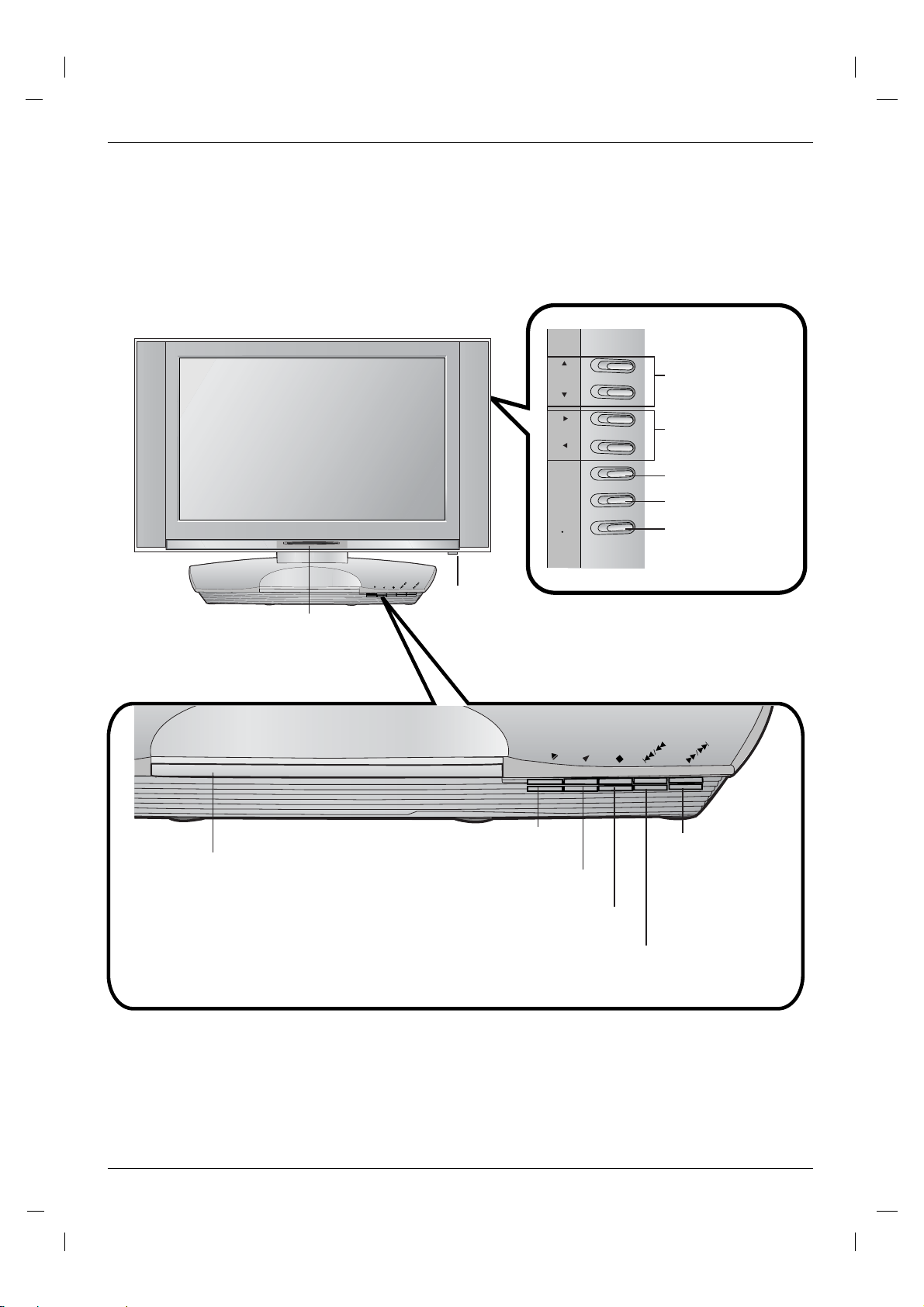
Controls
Controls
- This is a simplified representation of front panel.
- Here shown may be somewhat different from your TV.
DVD / CD PLAYER
Remote Control Sensor
Illuminates red in standby mode, illuminates
Power/Standby Indicator
green when the set is switched on.
DVD / CD PLAYER
CH
VOL
ENTER
MENU
TV
VIDEO
SKIP/
SKIP/
OPEN/
SCAN
SCAN
PLAY
CLOSE
STOP
ON/OFF Button
OPEN/
CLOSE
PLAY
STOP
Channel (
Buttons
Volume (F / G)
Buttons
ENTER Button
MENU Button
TVvVIDEO Button
SKIP/
SKIP/
SCAN
SCAN
D/E
)
Disc Tray
Insert a disc here.
OPEN/CLOSE Button
Opens or closes the disc tray
PLAY Button
Starts playback.
STOP Button
Stops playback.
Forward SKIP (GGI) /
SCAN ( GG) Button
• Go to the next chapter /
track.
• Press and hold for two
seconds for last forward
search.
Reverse SKIP (IFF) / SCAN (FF) Button
• Go to previous chapter/track or to the beginning.
• Press and hold for two seconds for fast reverse search.
Introduction
Introduction
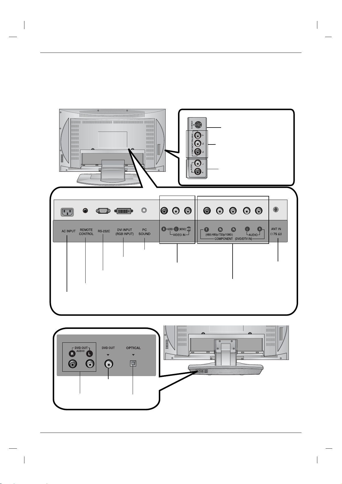
Connection Options
Connection Options
S-VIDEO INPUT
COMPONENT2 IN
(480i)
AUDIO INPUT
REMOTE CONTROL
AC INPUT
DVD Output
(Audio)
DVI INPUT
(RGB INPUT)
RS 232C JACK
JACK
VIDEO DIGITAL SOUND OUT
DVD Output
(Video)
(Digital Sound Output)
PC SOUND INPUT
OPTICAL
AUDIO/VIDEO
INPUT
1
ANTENNA
INPUT
COMPONENT1 (DVD/DTV IN)
((480i/480p/720p/1080i), Audio)
Installation
Installation
Basic Connection
Basic Connection
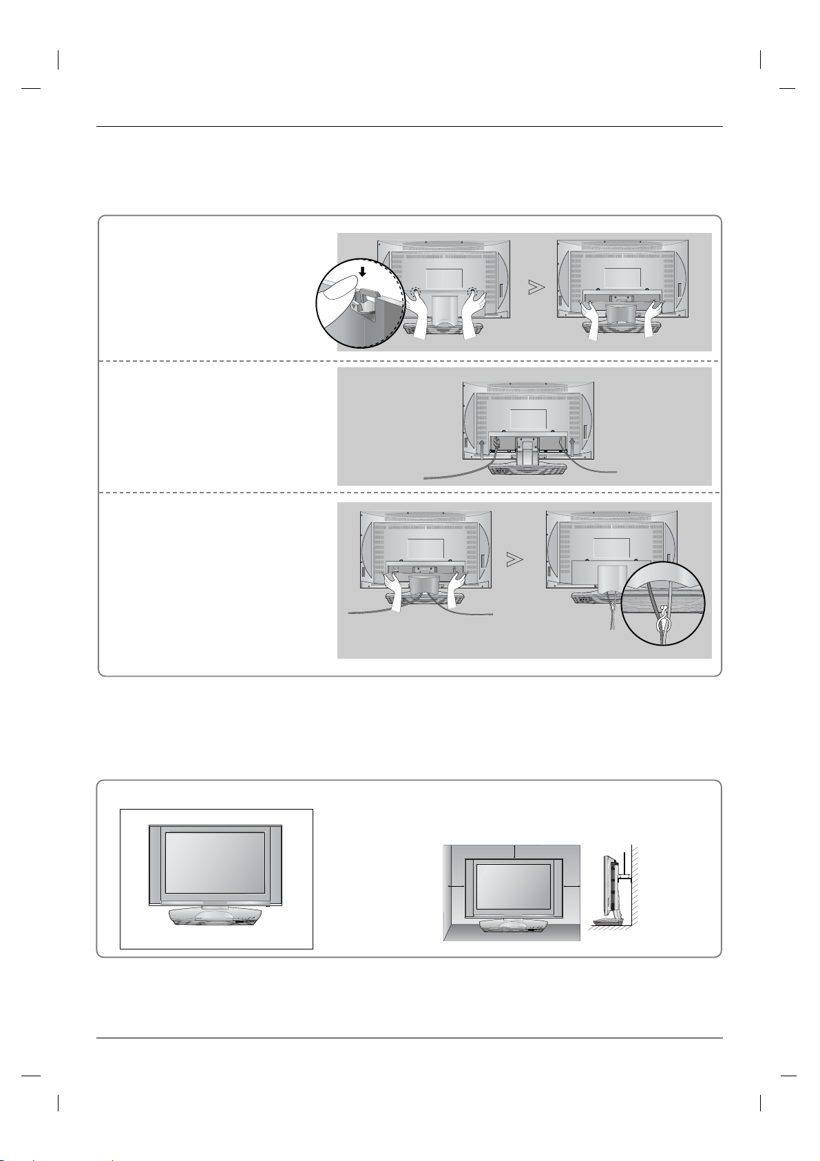
Pull the back cover backside
1
while pushing the two tabs and
then lift it up.
Connect the cables as necessary.
2
To connect an additional equipment,
see the External equipment
Connections section.
Align the holes on the TV back
3
panel with the four protuberance
on the rear AV cover and insert.
- Cable Arranagement
Pull the cables through the hole on
the set and bundle the cables using
the supplied twister holder.
Desktop Pedestal Installation
/
/
N
Y
/
PE
P
LA
E
I
KIP
SE
O
P
P
S
S
K
O
O
U
S
L
/
T
A
C
S
P
/
DVD / CD PLAYER
For proper ventilation, allow a clearance of 4" on each side and from
the wall.
4 inches
4 inches
4 inches
4 inches
/
N/
E
AY
P
/
I
E
L
E
P
IP
K
S
P
S
P
O
K
S
O
O
U
S
L
T
/
A
C
S
P
/
DVD / CD PLAYER
External Equipment Connections
External Equipment Connections
To prevent the equipment damage, never plug in any power cords until you have finished connecting all
equipment.
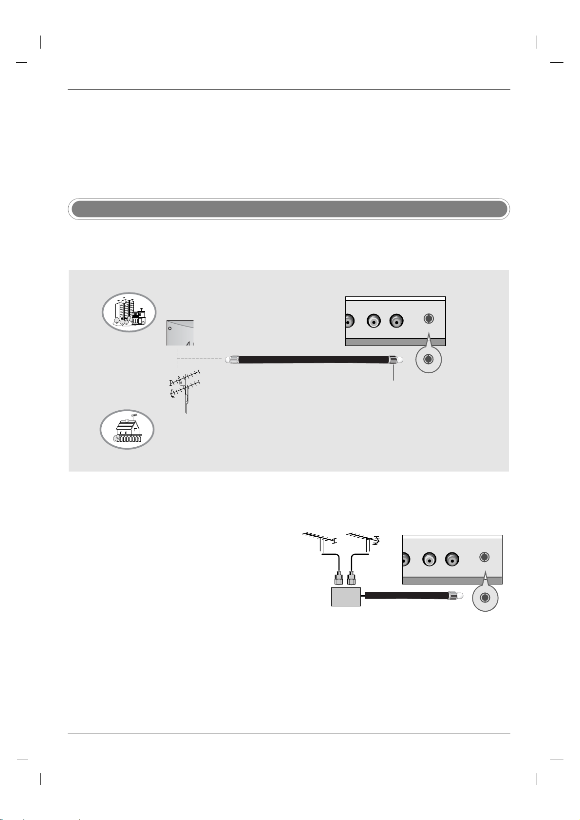
Antenna Connection
- For optimum picture quality, adjust antenna direction.
- An antenna cable and converter are not supplied.
Multi-family Dwellings/Apartments
(Connect to wall antenna socket)
Wall Antenna Socket
RF Coaxial Wire (75 ohm)
VHF Antenna
UHF Antenna
Outdoor Antenna
Single-family Dwellings /Houses
(Connect to wall jack for outdoor antenna)
• In poor signal areas, to get better picture quality, install a sig-
nal amplifier to the antenna as shown to the right.
• If signal needs to be split for two TVs, use an antenna sig-
nal splitter for connection.
Turn clockwise to tighten.
VHF
Signal
Amplifier
UHF
Installation
Installation
External Equipment Connections
External Equipment Connections
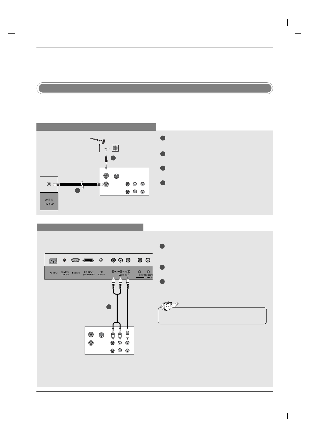
VCR Setup
- To avoid picture noise (interference), leave an adequate distance between the VCR and TV.
- Typically a frozen still picture from a VCR. If the 4:3 picture format is used; the fixed images on the sides of the
screen may remain visible on the screen.
When connecting with an antenna cable
1
Connect the RF antenna out socket of the VCR to
the Antenna socket on the set.
Connect the antenna cable to the RF antenna in
2
socket of the VCR.
Set VCR output switch to 3 or 4 and then tune TV
3
to the same channel number.
Insert a video tape into the VCR and press PLAY
4
on the VCR. (Refer to the VCR owner’s manual.)
TV Back panel
2
ANT IN
S-VIDEO
ANT OUT
1
OUT
(R) AUDIO (L)
IN
VIDEO
VCR
When connecting with a RCA cable
TV Back panel
1
ANT IN
S-VIDEO
ANT OUT
OUT
IN
VCR
(R) AUDIO (L)
VIDEO
1
Connect the AUDIO/VIDEO jacks between TV
and VCR. Match the jack colors (Video = yellow,
Audio Left = white, and Audio Right = red)
Insert a video tape into the VCR and press PLAY
2
on the VCR. (Refer to the VCR owner’s manual.)
3
Select Video input source with using the TV/AV
button on the remote control.
• If you have a mono VCR, connect the audio cable
from the VCR to the AUDIO L/MONO jack of the set.
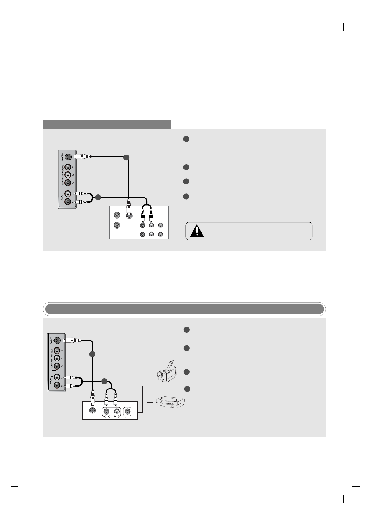
When connecting with an S-Video cable
TV side panel
1
2
ANT IN
S-VIDEO
ANT OUT
OUT
IN
VCR
(R) AUDIO (L)
VIDEO
1
Connect the an S-VIDEO output of the VCR to the
S-VIDEO input on the set. The picture quality is
improved; compared to connecting a regular VCR
to the Video input.
Connect the audio outputs of the VCR to the
2
AUDIO input jacks on the set.
3
Insert a video tape into the VCR and press PLAY
on the VCR. (Refer to the VCR owner’s manual.)
4
Select S-Video input source with using the TV/AV
button on the remote control.
Do not connect to both Video and S-Video at
the same time.
TV side panel
1
2
S-VIDEO
AUDIO VIDEO
RL
External Equipment
External AV Source Setup
1
Connect the S-VIDEO output of the external
equipment to the S-VIDEO input on the set.
Connect the AUDIO jacks between TV and exter-
2
nal equipment. Match the jack colors (Video = yellow, Audio Left = white, and Audio Right = red).
3
Select S-Video input source with using the TV/AV
Camcorder
Video Game Set
button on the remote control.
4
Operate the corresponding external equipment.
Refer to external equipment operating guide.
Installation
Installation
External Equipment Connections
External Equipment Connections
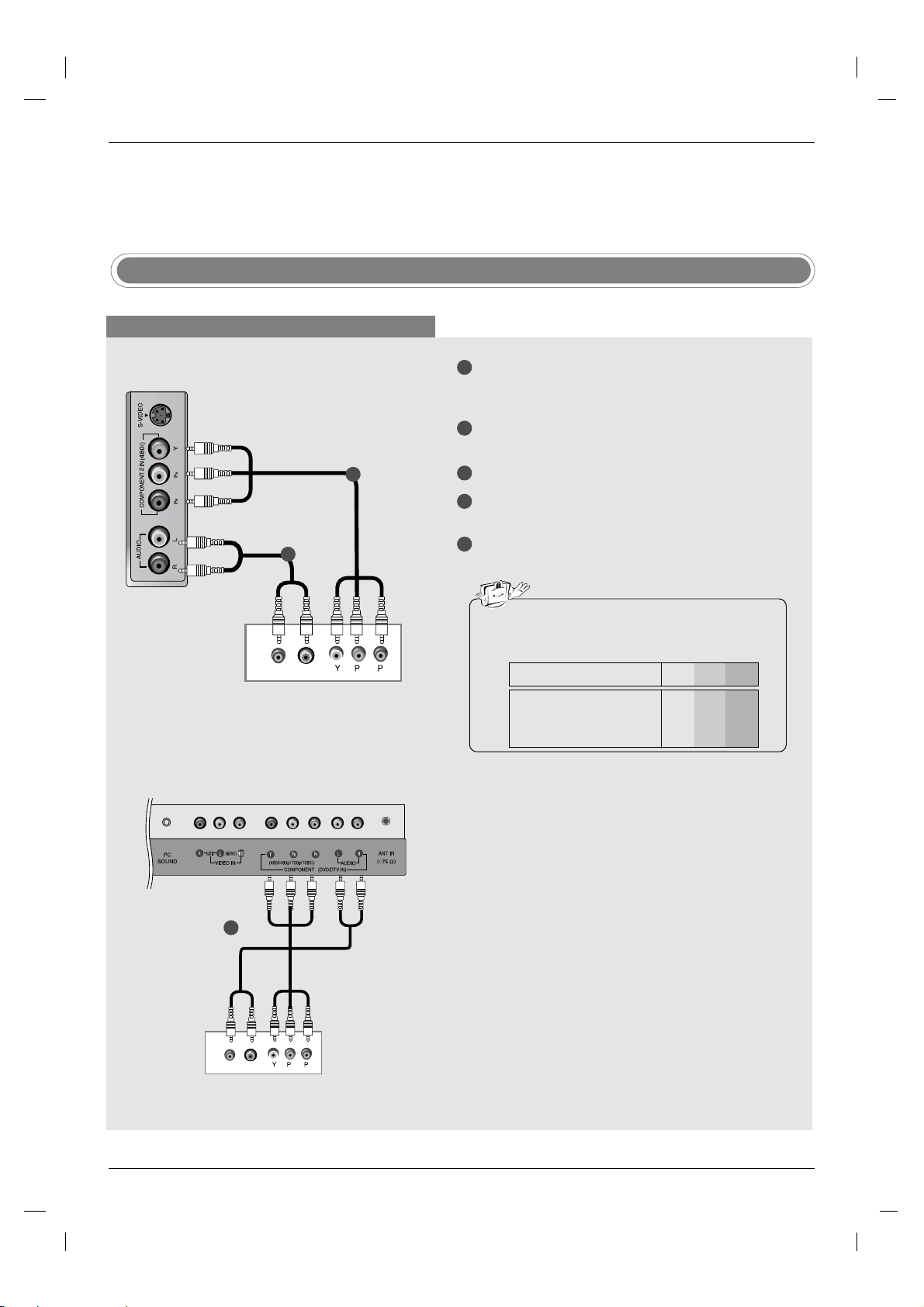
External DVD Setup
When connecting with a component cable
1
TV side panel
2
(R) AUDIO (L)
DVD
1
B
R
Connect the video outputs (Y, PB, PR) of the DVD
to the COMPONENT DVD IN (Y, P
the set.
2
Connect the audio outputs of the DVD to the
AUDIO input jacks on the set.
Turn on the DVD player, insert a DVD.
3
Select COMPONENT input source with using the
4
TV/AV button on the remote control.
5
Refer to the DVD player's manual for operating
instructions.
B, PR) jacks on
• Component Input ports
To get better picture quality, connect a DVD player
to the component input ports as shown below.
Y P
Component ports on the TV
Video output ports
on DVD player
B
Y
Pb
B-Y
Cb
P
R-Y
B
Y
Y
Y
PR
Pr
Cr
P
R
1
(R) AUDIO (L)
TV back panel
1
B
R
DVD

When connecting with a S-Video cable
TV side panel
1
Connect the S-VIDEO output of the DVD to the
S-VIDEO input on the set.
Connect the audio outputs of the DVD to the
2
AUDIO input jacks on the set.
1
2
Turn on the DVD player, insert a DVD.
3
4
Select S-VIDEO input source with using the
TV/AV button on the remote control.
5
Refer to the DVD player's manual for operating
instructions.
(R) AUDIO (L)
S-VIDEO
DVD
DVD Output Setup
The TV has a special signal output capability which allows you to hook up a second TV or monitor.
1
Connect the second TV or monitor to the TV’s DVD
OUT (VIDEO) and DVD OUT (AUDIO) jacks.
2
See the Operating Manual of the second TV or
monitor for further details regarding that device’s
input settings.
1
Connect the second TV or monitor to the TV’s DVD
OUT (VIDEO) and OPTICAL DIGITAL SOUND
OUT jacks.
2
See the Operating Manual of the second TV or
monitor for further details regarding that device’s
input settings.
DIGITAL SOUND OUT
VIDEO DIGITAL SOUND OUT
TV Back Panel
(Stand)
VIDEO
TV Back Panel
(Stand)
OR
DIGITAL AUDIO
VIDEO
AUDIO (L)
(R)
Second TV or Monitor
Notes
a.
If your second TV or monitor has no optical digital audio input jack, it’s impossible to use DVD digital sound
input terminals
VIDEO
Second TV or Monitor
input terminals
OPTICAL
output.
b.
Do not look into the optical output port. Looking at the laser beam may damage your vision.
c.
If your external audio equipment has a digital audio input optical port, you can connect it to your TV.

Installation
Installation
External Equipment Connections
External Equipment Connections
DTV Setup
When connecting with a component cable
TV side panel
1
2
1
2
3
4
Connect the video outputs (Y, PB, PR) of the digital set-top box to the COMPONENT DVD IN (Y,
PB, P
R) jacks on the set.
Connect the audio outputs of the digital set-top
box to the AUDIO input jacks on the set.
Turn on the digital set-top box. (Refer to the
owner’s manual for the digital set-top box.)
Select COMPONENT input source with using the
TV/AV button on the remote control.
(R) AUDIO (L)
B
R
DTV Receiver (Set-top Box)
PC Setup
1
Connect the TV to the PC with the PC cable.
2
Connect the PC audio output to the TV's PC SOUND input.
3
Turn on the PC.
Use the TV/AV button on the remote control to select PC.
4
NOTE
Connect the signal cable (DVI-D cable, Not
DVI to D-Sub cable) from the DVI output socket of the PC to the DVI input socket of the set
when using a PC with DVI output. In some
video cards, DVI-Analog output may not be
supported.

Monitor Display Specifications
MODE Resolution
VGA
640x480
Horizontal
Frequency(kHz)
31.4
Vertical
Frequency(Hz)
60
a. For optimum picture quality, use standard WXGA
Notes
1280x768 computer output at a 60Hz refresh rate.
Using other formats (VGA, SVGA, etc.) or refresh
SVGA
800x600
37.8
60
rates may result in reduced picture quality. (To
change the computer video output format, please
XGA
1024x768
48.3
60
refer to the operating manual for the computer you
are using).
WXGA
1280x768
1360x768
47.6
47.6
60
60
b. If the message
screen, adjust the PC output to a format listed in
the Monitor Display Specifications table.
c. The synchronization input form for Horizontal and
Vertical frequencies is separate.
DPM (Display Power Management) mode
If the PC goes to power saving mode, the monitor automatically switches to DPM mode.
If you don’t use the PC cable provided, DPM mode may not work.
Out of range appears on the
Power Cord Connection
- Connect the power cord correctly as shown.
AC INPUT

Setting up TV stations
Setting up TV stations
Memorizing the Channels with EZ scan
Channel
EZ Scan
Manual prog.
Favorite ch.
D
FG
OK MENU
E
- For Auto program to work, the programming source must be connected
Channel
EZ Scan
Manual prog.
Favorite ch.
D
FG
OK MENU
E
Press the MENU button and then use
1
To start
Channel menu.
D /E
to the TV and the TV must be receiving programming signals either overthe-air or from a cable-type service
provider.
Press the Gbutton and then use
2
Press the
3
G
button to begin the channel search.
button to select EZ Scan.
D /E
• Wait for auto program to complete the channel search cycle before
choosing a channel. The TV scans for over-the-air channels and
then channels provided by a cable service.
Notes
a. When the channel search is complete, use the
buttons to review the memorized channels.
D /E
b. If you press the ENTER button in auto programming, the function will stop and only channels program-
ming up to that time will remain.
c. Auto program function can memorize only the channels which are being received at that time.
button to select the

Add/Delete Channels with Manual program
Channel
EZ Scan
Manual prog.
Favorite ch.
D
FG
OK MENU
E
- You can manually include or erase
individual channels.
Channel
EZ Scan
Manual prog.
Favorite ch.
D
FG
OK MENUÂEXIT
E
1
Press the MENU button and then use
TV 30
Memory
The current channel number
is displayed.
button to select the Channel
D /E
menu.
2
Press the
Press the
3
G
button and then use
G
button and then use
button to select Manual prog..
D /E
button to select a channel you
D /E
want to add to memory or erase.
4
Press the
button and then use
E
button to select Memory (add)
D /E
or Erase (delete).
Press the ENTER button to save. The current channel is added to
5
Memory or Erased from the channel list.
Favourite Channels Setup
Channel Favorite Ch.
EZ Scan
Manual prog.
Favorite ch.
D
FG
OK MENU
E
- Favorite Channel lets you quickly
tune in up to 8 channels of your
To set
1
Press the MENU button and then use
menu.
choice without having to wait for the
TV to scan through all the inbetween channels.
FRC
FCR
AUDIO
PAUSE/STEP
SCAN
OPEN/CLOSE
CC
AUDIO
MTS
REPEAT
TV/AV
MULTIMEDIA
VIDEO
STOP
POWER
PLAY
SCAN
Press the
2
Press the
3
channel position.
Use the
4
channel.
Repeat steps 3 to 4 to memorize other channels.
5
Press the ENTER button to save.
6
G
G
F /G
- - - - - - - - - -
- - - - - - - - - -
- - - - - - - - - -
- - - - - - - - - -
- - - - - - - - - -
- - - - - - - - - -
- - - - - - - - - -
- - - - - - - - - -
D
FG
OK MENUÂEXIT
E
button to select the Channel
D /E
button and then use
button and then use
button to select Favorite ch..
D /E
button to select the first favorite
D /E
button to set the desired channel number for first favorite

Picture Menu Options
Picture Menu Options
EZ Video
Picture
EZ Video
User
Cinema
D
FG
OK MENU
E
-
This function adjusts the TV for the
best picture appearance.
FCR
AUDIO
PAUSE/STEP
OPEN/CLOSE
CC
AUDIO
MTS
REPEAT
TV/AV
MULTIMEDIA
Video
VIDEO
STOP
PLAY
Picture
EZ Video
User
Cinema
D
FG
E
POWER
OK MENU
Picture
EZ Video
User
Cinema
D
FG
OK MENU
E
Press the MENU button and then
1
Press the
2
Press the
3
G
button and then
G
button and then
Clear
Optimum
Soft
User
D /E
D /E
D /E
EZ Video menu.
Press the ENTER button.
4
Manual Picture Control (User option)
Picture
EZ Video
User
Cinema
D
FG
E
OK MENU
Contrast G
Brightness G
Color G
Sharpness G
Tint G
button to select the Picture menu.
button to select EZ Video.
button to select a picture setting on the
D
Contrast 85 F
E
G
Press the MENU button and then
- You can adjust picture contrast,
1
brightness, color, sharpness and tint
to the levels you prefer.
Press the Gbutton and then use
2
Press the
3
picture option (Contrast, Brightness, Color, Sharpness, Tint).
Use the
4
•
Contrast, Brightness, Color, and Sharpness are adjustable from 0 to 100.
• Tint is adjustable from - 50 to + 50.
Press the ENTER button to save.
5
Notes
a. Only Contrast and Brightness are displayed in PC mode.
D /E
button to select User.
D /E
G
button and then use
button to make appropriate adjustments.
D /E
button to select the desired
D /E
button to select the Picture menu.

Picture Menu Options
Picture Menu Options
Cinema Mode Setup
Picture
EZ Video
User
Cinema
D
FG
OK MENU
E
- Sets up the TV for the best picture
appearance for viewing movies.
Picture format (ARC-Aspect Ratio Correction)
Picture
EZ Video
User
Cinema
D
FG
OK MENU
E
1
Press the MENU button and then use
On
Off
menu.
G
Press the
2
Press the
3
Press the ENTER button to save.
4
button and then use
G
button and then use
button to select the
D /E
button to select Cimena.
D /E
button to to select On or Off.
D /E
Picture
TV/AV
MULTIMEDIA
VIDEO
STOP
SKIP
MENU
DISC MENU
VOL
POWER
PLAY
SCAN
ARC
TITLE
MUTE
FCR
AUDIO
PAUSE/STEP
SCAN
ARC
ENTER
DISPLAY
FLASHBK
OPEN/CLOSE
CC
AUDIO
MTS
REPEAT
SKIP
EXIT
RETURN
CH
- You can watch TV in various picture formats; 16:9, Zoom, 4:3.
Repeatedly press the ARC button to select your desired picture format.
• 16:9
Displays video in 16:9 Widescreen mode. A 4:3 signal will be stretched to fill
the screen.
• Zoom
A 4:3 signal is magnified to the upper / lower and left / right sides so that the
signal fills the16:9 screen. The bottom and top of the picture will be cut off.
• 4:3
Standard TV format.
Notes
a.
Zoom is not available in PC mode.

Sound Menu Options
Sound Menu Options
EZ Audio
Sound
EZ Audio
AVL
Balance
D
FG
OK MENU
E
- This function lets you enjoy the best
sound without any special adjustment because the TV selects the
appropriate sound option based on
the program content.
FCR
AUDIO
PAUSE/STEP
OPEN/CLOSE
CC
AUDIO
MTS
REPEAT
TV/AV
MULTIMEDIA
VIDEO
STOP
POWER
AUDIO
PLAY
Sound
EZ Audio
AVL
Balance
D
FG
OK MENU
E
Press the MENU button and then
1
G
Press the
2
Press the
3
button and then
G
button and then use the
Flat G
Music
Movie
Sports
User
D /E
D /E
sound option; Flat, Music, Movie, Sports.
Press the ENTER button to save.
4
button to select the Sound menu.
button to select EZ Audio.
button to select the appropriate
D /E
Sound
EZ Audio
AVL
Balance
D
FG
E
OK MENU
EQualizer Adjustments
Sound
EZ Audio
AVL
Balance
D
FG
OK MENU
E
Press the MENU button and then
1
Press the
2
3
Press the
Press the
4
G
G
G
want to adjust. Then, use the
Press the ENTER button to save.
5
Flat
Music
Movie
Sports
User
button and then
button and then use the
button and then use the
G
button to select the Sound menu.
D /E
button to select EZ Audio.
D /E
button to select User.
D /E
F /G
button to select the band you
button to adjust the band level.
D /E
0.1 0.5 1 5 10 KHz
D
FG
Move AdjustÂExit
E

Sound Menu Options
Sound Menu Options
AVL (
Auto Volume Leveler)
Sound
EZ Audio
AVL
Balance
D
F
OK MENU
E
- AVL (Auto Volume Leveler) maintains
an equal volume level automatically
even if the programme is changed.
Sound
EZ Audio
AVL
Balance
Sound
EZ Audio
AVL
Balance
D
F
OK MENU
E
1
Press the MENU button and then
G
Press the
2
3
Press the
Press the ENTER button to save.
4
button and then
G
button and then use the
Sound Balance
Sound
EZ Audio
AVL
Balance
On
Off
D /E
button to select AVL.
D /E
D /E
0
button to select the Sound menu.
button to select On or Off.
D
F
E
OK MENU
D
FG
OK MENU
E
1
Press the MENU button and then
2
Press the
3
Press the
G
button and then
G
button and then use the
D /E
button to select the Sound menu.
D /E
button to select Balance.
F /G
balance.
• Balance is adjustable from Left 50 to Right 50.
4
Press the ENTER button to save.
button to adjust the sound

Sound Menu Options
Sound Menu Options
Stereo/SAP Broadcasts Setup
- The TV can receive MTS stereo programs and any SAP (Secondary
Audio Program) that accompanies the stereo program, if the broadcaster
transmits an additional sound signal as well as the original one.
- Mono: The primary language is heard from left and right speakers.
Signal mode is mono.
- Stereo: The primary language is heard from left and right speakers.
Signal mode is stereo.
- SAP: The secondary language is heard from left and right speakers.
TV/AV
MULTIMEDIA
VIDEO
STOP
POWER
FCR
AUDIO
PLAY
OPEN/CLOSE
PAUSE/STEP
CC
AUDIO
MTS
MTS
REPEAT
SKIP
MENU
SCAN
ENTER
ARC
SCAN
SKIP
EXIT
1. Press the MTS button repeatedly.
• Select mono sound mode if the signal is not clear or in poor signal
reception areas.
• Stereo, SAP mode are available only if included on the broadcast signal.

imer menu Options
TTimer menu Options
Auto Clock Setup
Timer
Clock
Off timer
On timer
Auto off
D
FG
OK MENU
E
- The time can be automatically set
using information from your local
PBS TV station. The PBS channel
signal includes information for the
correct time and daylight savings
time.
Timer
Clock
Off timer
On timer
Auto off
D
FG
OK MENU
E
Press the MENU button and then use
1
menu.
Press the
2
Press the
3
Press the
4
for your viewing area. Your choices are: Auto, E.S.T. (Eastern
G
G
G
Standard Time), C
Auto G
Manual
button and then use
button and then use
button and then use
(Central Standard Time), M.S.T. (Mountain
.S.T.
D /E
button to select Clock.
D /E
button to select Auto.
D /E
button to select the time zone
D /E
Time zone Auto
PBS Ch. TV 1
D.S.T. Auto
FG
Move AdjustÂExit
button to select the Timer
Standard Time), P. S . T . (Pacific Standard Time), Alaska
Press the
5
Press the
6
Savings Time) Auto
G
button and then use
G
button and then use
, Off or On,
button to set PBS channel.
D /E
button to set D.S.T. (Daylight
D /E
depending on whether or not your
viewing area observes Daylight Savings Time.
Press the ENTER button to save.
7
Auto Clock
D
E
and Hawaii.
,
Timer
Clock
Off timer
On timer
Auto off
D
FG
OK MENU
E
- If the time on the clock is incorrect,
reset the clock manually.
Auto Clock Setup
Timer
Clock
Off timer
On timer
Auto off
D
FG
OK MENU
E
Press the MENU button and then
1
Press the
2
Press the
3
Press the
4
Press the ENTER button to save.
5
G
G
G
Auto
Manual
- - : - - AM
button and then
button and then
button and then
button to select the TIME menu.
D/E
button to select TIME.
D/E
button to adjust the hour.
D/E
button to adjust the minute.
D/E

A-B
SLEEP butt
RANDOM
SEARCH
MARKER
imer menu Options
TTimer menu Options
ANGLE
PROGRAM
SUB_T
ZOOM
To cancel the Sleep Timer, press the SLEEP button repeatedly until
4
Sleep --- appears.
on once.

Auto off
Timer
Clock
Off timer
On timer
Auto off
D
FG
OK MENU
E
- If you select On on the Auto off
menu, the set will automatically switch
itself to standby mode approximately
ten minutes after a TV station stops
broadcasting.
- In the
Component, or PC mode,
Auto off is not available.
Timer
Clock
Off timer
On timer
Auto off
D
FG
OK MENU
E
1
Press the MENU button and then
Press the
2
Press the
3
Press the ENTER button to save.
4
G
button and then
G
button and then
On
Off
button to select the TIME menu.
D/E
button to select Auto off.
D/E
button to select On or Off.
D/E

Special Menu Options
Special Menu Options
Closed Captions
Closed Captions
Closed captioning is a process which converts the audio portion of a television program into written words which then appear as subtitles on the television screen. Closed captions allow viewers to read the dialogue and narration of television programs.
Using Closed Captions
Captions are the subtitles of the dialogue and narration of television programs. For prerecorded
programs, program dialogue can be arranged into captions in advance. Its possible to caption a
live program by using a process called real-time captioning, which creates captions instantly.
Real-time captioning is normally done by professional reporters using a machine shorthand system and computer for translation into English.
Captioning is an effective system for the hearing-impaired, and it can also aid in teaching lan-
FOLLOW ME
guage skills.
• The picture at left shows a typical caption.
Caption Tips
• Not all TV broadcasts include closed caption signals.
• Sometimes TV stations broadcast four different caption signals on the same channel. By selecting
choose which signal you view.
programming information.
• Your TV might not receive caption signals normally in the following situations.
1. Poor reception conditions are encountered:
CC 1 is usually the signal with the captions, while Another mode might show demonstration or
From CC 1 to CC 4, you can
• IGNITION:
Picture may flutter, drift, suffer from black spots, or horizontal streaking. Usually caused by interference from automobile ignition systems, neon lamps, electrical drills, and other electrical appliances.
• GHOSTS:
Ghosts are caused when the TV signal splits and follows two paths. One is the direct path and the
other is reflected off tall buildings, hills or other objects. Changing the direction or position of the
antenna may improve reception.
• SNOW:
If your receiver is located at the weak, fringe area of a TV signal, your picture may be marred by
small dots. It may be necessary to install a special antenna to improve the picture.
2. An old, bad, or illegally recorded tape is being played.
3. Strong, random signals from a car or airplane interfere with the TV signal.
4. The signal from the antenna is weak.
5. The program wasn’t captioned when it was produced, transmitted, or taped.

Caption/Text
Special
Language
Caption/Text
Captions
Key lock
Parental
Logo
D
FG
OK MENU
E
Special
Language
Caption/Text
Captions
Key lock
Parental
Logo
D
FG
OK MENU
E
Press the MENU button and then use
1
CC1
CC2
CC3
CC4
Text1
Text2
Text3
Text4
D /E
button to select the Special
menu.
G
Press the
2
Press the Gbutton and then use
3
button and then use
button to select Caption / Text
D /E
button to select caption: CC1, CC2,
D /E
CC3, CC4, Text1, Text2, Text3, or Text4.
• CAPTION
The term for the words that scroll across the bottom of the TV screen;
usually the audio portion of the program provided for the hearing
impaired.
• TEXT
The term for the words that appear in a large black frame and almost
cover the entire screen; usually messages provided by the broadcaster.
Press the ENTER button to save.
4
.
TV/AV
MULTIMEDIA
VIDEO
STOP
POWER
FCR
AUDIO
PLAY
OPEN/CLOSE
PAUSE/STEP
CC
CC
AUDIO
MTS
REPEAT
Captions
Use the CC button repeatedly to select Caption Off, EZ Mute or On.
1
• EZ Mute shows the selected captions option (if available on program)
when the TV sound is muted
Press the ENTER button to save.
2

Key Lock
Special
Language
Caption/Text
Captions
Key lock
Parental
Logo
D
FG
OK MENU
E
- The TV can be set up so that it can
only be used with the remote control
to prevent unauthorized viewing.
Special
Language
Caption/Text
Captions
Key lock
Parental
Logo
Special
Language
Caption/Text
Captions
Key lock
Parental
Logo
D
FG
OK MENU
E
Press the MENU button and then
1
G
Press the
2
Press the Gbutton and then
3
Press the ENTER button to save.
4
button and then
On
Off
D /E
D /E
D /E
Lightening Logo Display Lamp
Special
Language
Caption/Text
Captions
Key lock
Parental
Logo
On
Off
button to select the Special menu.
button to select Key lock.
button to select On or Off.
D
FG
OK MENU
E
- If you select on, “Liquid Crystal
Display” of TV front panel turns
on.
D
FG
OK MENU
E
Press the MENU button and then
1
Press the
2
Press the Gbutton and then
3
Press the ENTER button to save.
4
G
button and then use
button to select the Special menu.
D /E
button to select Logo.
D /E
button to select On or Off.
D /E

Parental Menu Options
Parental Menu Options
Parental Control can be used to block specific channels, ratings and other viewing sources.
The Parental Control Function (V-Chip) is used to block program viewing based on the ratings sent by the broadcast station. The
default setting is to allow all programs to be viewed. Viewing can be blocked by the type of program and by the categories chosen
to be blocked. It is also possible to block all program viewing for a time period. To use this function, the following must be set :
1. Ratings and categories to be blocked.
2. Set a password
3. Enable the lock
V-Chip rating and categories
Rating guidelines are provided by broadcast stations. Most television programs and television movies can be blocked by TV
Rating and/or Individual Categories. Movies that have been shown at the theaters or direct-to-video movies use the Movie Rating
System (MPAA) only.
For Movies previously shown in theaters :
Movie Ratings :
• Unblocked
• G and Above (general audience)
• PG and Above (parental guidance suggested)
• PG-13 and Above (13 years and older)
• R and above (restricted)
• NC-17 and Above (18 years and older)
• X (adult)
If you set PG-13 and Above : G and PG movies will be available , PG-13, R, NC-17 and X will be blocked.
For Television programs including made-for-TV movies:
General TV Ratings:
• Unblocked
• TV-G and Above (general audience) (individual categories do not apply)
• TV-PG and Above (parental guidance suggested)
• TV-14 and Above (14 years and older)
• TV-MA (mature audience)
Children TV Ratings:
• Unblocked
• TV-Y and Above (youth) (individual content categories do not apply)
• TV-Y7 (youth, 7 years and up)
Content Categories:
• Dialog - sexual dialogue (applies to TV-PG and Above, TV-14)
• Language - adult language (applies to TV-PG and Above, TV-14 and Above, TV-MA)
• Sex scenes - sexual situations (applies to TV-PG and Above, TV-14 and Above, TV-MA)
• Violence (applies to TV-PG and Above, TV-14 and Above, TV-MA)
• F Violence - fantasy violence (applies only to TV-Y7)
• No Rating (blocks all viewing)
For Canadian English/French language rating system:
Canadian English language rating system:
• C and Above (Children)
• C8+ (8 years and older)
• G and Above (General programming. Suitable for all audiences.)
• PG and Above (Parental guidance suggested)
• 14+ (Viewer 14 years and older)
• 18+ (Adult programming)
Canadian French language rating system:
• G and Above (General)
• 8 ans+ (8 years and older)
• 13 ans+ (13 years and older)
• 16 ans+ (16 years and older)
• 18 ans+ (Adults only)

PC Menu Options
PC Menu Options
After setup, be sure to select PC source to see the PC image the on TV screen.
Auto Configure
PC
H-Position
V-Position
Clock
Phase
Auto Configure
Reset
D
FG
OK MENU
E
- Automatically adjusts the screen position, clock, and clock phase. (The displayed image will disappear for a few
seconds while Auto-configuration is in
progress.)
PC
H-Position
V-Position
Clock
Phase
Auto Configure
Reset
PC
H-Position
V-Position
Clock
Phase
Auto Configure
Reset
D
FG
OK MENU
E
Press the
1
MENU
button and then use the
menu.
G
Press the
2
button and then use the
Configure.
G
Press the
3
button to start Auto Configure.
H-Position / V-Position
PC
H-Position
V-Position
Clock
Phase
Auto Configure
Reset
To Set
button to select the PC
D /E
button to select Auto
D /E
85
Press the
1
D
E
FG
OK MENU
MENU
button and then use the
button to select the PC menu.
D /E
D
FG
OK MENU
E
• H position / V Position
This function is to adjust picture to
left/right and up/down as you prefer.
Press the
2
G
button and then use the
button to select H-Position or
D /E
V-Position.
F /G
Use the
3
button to make appropriate adjustments.
Notes
Depending on the specification of the PC you are playing the DVD VIDEO on, and the DVD's title, some
scenes may be skipped, or you may not be able to pause during multi-angle scenes.

Clock / Phase
PC
H-Position
V-Position
Clock
Phase
Auto Configure
Reset
D
FG
OK MENU
E
• Clock
This function is to minimize any vertical
bars or stripes visible on the screen background. And the horizontal screen size
will also change.
• Phase
This function allows you to remove any
horizontal noise and clear or sharpen the
image of characters.
PC
H-Position
V-Position
Clock
Phase
Auto Configure
Reset
PC
H-Position
V-Position
Clock
Phase
Auto Configure
Reset
D
FG
OK MENU
E
Press the
1
2
Press the
3
Use the
Press the ENTER button to save.
4
MENU
button and then use the
G
button and then use the
F /G
button to make appropriate adjustments.
Reset
PC
H-Position
V-Position
Clock
Phase
Auto Configure
Reset
To Set
85
button to select the PC menu.
D /E
button to select Clock or Phase.
D /E
D
FG
OK MENU
E
- Returns to the default settings programmed at the factory; default settings cannot be changed.
D
FG
OK MENU
E
Press the MENU button and then use the
1
G
Press the
2
Press the
3
button and then use the
G
button to start Reset.
button to select the PC menu.
D /E
button to select Reset.
D /E

Reference
Reference
External Control Device Setup ; RS-232C
External Control Device Setup ; RS-232C
- Connect the RS-232C input jack to an external control device (such as a computer or an A/V control system) and control the TV’s functions externally.
- Connect the serial port of the control device to the RS-232C jack on the TV back panel.
- RS-232C connection cable is not supplied with the TV.
RS-232C Setup
RS-232C Setup
PC
ype of Connector; D-Sub 9-Pin Male
TType of Connector; D-Sub 9-Pin Male
No. Pin name
1 No connection
2 RXD (Receive data)
3 TXD (Transmit data)
4 DTR (DTE side ready)
5 GND
6 DSR (DCE side ready)
7 RTS (Ready to send)
8 CTS (Clear to send)
9 No Connection
RS-232C Configurations
RS-232C Configurations
7-Wire Configurations
(Standard RS-232C cable)
RXD
TXD
GND
DTR
DSR
RTS
CTS
PC
2
3
5
4
6
7
8
TV
TXD
3
RXD
2
GND
5
DSR
6
DTR
4
CTS
8
RTS
7
RXD
TXD
GND
DTR
DSR
RTS
CTS
3-Wire Configurations
(Not standard)
PC
2
3
5
4
6
7
8
TV
1
5
9
6
TXD
3
RXD
2
GND
5
DTR
4
DSR
6
RTS
7
CTS
8
D-Sub 9
D-Sub 9
D-Sub 9
D-Sub 9

Reference
Reference
Maintenance
Maintenance
- Early malfunctions can be prevented. Careful and regular cleaning can extend the amount of time you will have
your new TV. Be sure to turn the power off and unplug the power cord before you begin any cleaning.
Cleaning the Screen
Cleaning the Screen
1. Here’s a great way to keep the dust off your screen for a while. Wet a soft cloth in a mixture of lukewarm water and a little fabric softener or dish washing detergent. Wring the cloth until it’s almost dry,
and then use it to wipe the screen.
2. Make sure the excess water is off the screen, and then let it air-dry before you turn on your TV.
Cleaning the Cabinet
Cleaning the Cabinet
To remove dirt or dust, wipe the cabinet with a soft, dry, lint-free cloth.
Please be sure not to use a wet cloth.
Extended
Extended
Product Specifications
Product Specifications
Absence
Absence
If you leave your TV dormant for a long time (such as a vacation), it’s a good idea to unplug
the power cord to protect against possible damage from lightning or power surges.
Power Requirement
Power Consumption
Television System
Television Channel
Television Screen
External Antenna Impedance
Audio Output
AC 100-240V~ 50/60Hz 1.4A
120W
NTSC , PAL - M/N
VHF : 2 ~ 13, UHF : 14 ~ 69, Cable : 01 ~ 125
LCD Panel
75 Ω
7 W + 7 W

 Loading...