

Page 1

LCD TV
SERVICE MANUAL
CAUTION
BEFORE SERVICING THE CHASSIS,
READ THE SAFETY PRECAUTIONS IN THIS MANUAL.
CHASSIS : LJ71A
MODEL : 23LS7D 23LS7D-JA
website:http://biz.LGservice.com
Page 2

- 2 -
CONTENTS
CONTENTS .............................................................................................. 2
SAFETY PRECAUTIONS ........................................................................ 3
SPECIFICATION ...................................................................................... 4
ADJUSTMENT INSTRUCTION ............................................................... 7
TROUBLE SHOOTING .......................................................................... 11
WIRING DIAGRAM ................................................................................ 17
BLOCK DIAGRAM ................................................................................. 18
EXPLODED VIEW .................................................................................. 20
REPLACEMENT PARTS LIST .............................................................. 22
SVC. SHEET ...............................................................................................
Page 3
- 3 -
SAFETY PRECAUTIONS
Many electrical and mechanical parts in this chassis have special safety-related characteristics. These parts are identified by in the
Schematic Diagram and Replacement Parts List.
It is essential that these special safety parts should be replaced with the same components as recommended in this manual to prevent
Shock, Fire, or other Hazards.
Do not modify the original design without permission of manufacturer.
General Guidance
An isolation Transformer should always be used during the
servicing of a receiver whose chassis is not isolated from the AC
power line. Use a transformer of adequate power rating as this
protects the technician from accidents resulting in personal injury
from electrical shocks.
It will also protect the receiver and it's components from being
damaged by accidental shorts of the circuitry that may be
inadvertently introduced during the service operation.
If any fuse (or Fusible Resistor) in this TV receiver is blown,
replace it with the specified.
When replacing a high wattage resistor (Oxide Metal Film Resistor,
over 1W), keep the resistor 10mm away from PCB.
Keep wires away from high voltage or high temperature parts.
Before returning the receiver to the customer,
always perform an AC leakage current check on the exposed
metallic parts of the cabinet, such as antennas, terminals, etc., to
be sure the set is safe to operate without damage of electrical
shock.
Leakage Current Cold Check(Antenna Cold Check)
With the instrument AC plug removed from AC source, connect an
electrical jumper across the two AC plug prongs. Place the AC
switch in the on position, connect one lead of ohm-meter to the AC
plug prongs tied together and touch other ohm-meter lead in turn to
each exposed metallic parts such as antenna terminals, phone
jacks, etc.
If the exposed metallic part has a return path to the chassis, the
measured resistance should be between 1MΩ and 5.2MΩ.
When the exposed metal has no return path to the chassis the
reading must be infinite.
An other abnormality exists that must be corrected before the
receiver is returned to the customer.
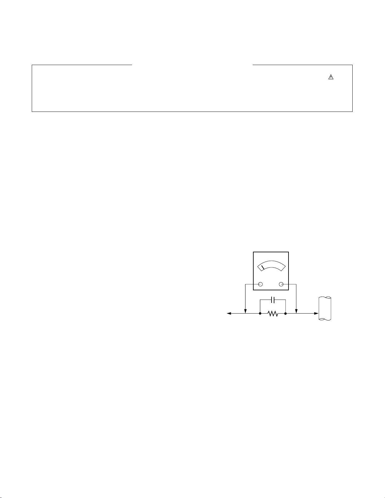
Leakage Current Hot Check (See below Figure)
Plug the AC cord directly into the AC outlet.
Do not use a line Isolation Transformer during this check.
Connect 1.5K/10watt resistor in parallel with a 0.15uF capacitor
between a known good earth ground (Water Pipe, Conduit, etc.)
and the exposed metallic parts.
Measure the AC voltage across the resistor using AC voltmeter
with 1000 ohms/volt or more sensitivity.
Reverse plug the AC cord into the AC outlet and repeat AC voltage
measurements for each exposed metallic part. Any voltage
measured must not exceed 0.75 volt RMS which is corresponds to
0.5mA.
In case any measurement is out of the limits specified, there is
possibility of shock hazard and the set must be checked and
repaired before it is returned to the customer.
Leakage Current Hot Check circuit
1.5 Kohm/10W
To Instrument’s
exposed
METALLIC PARTS
Good Earth Ground
such as WATER PIPE,
CONDUIT etc.
AC Volt-meter
IMPORTANT SAFETY NOTICE
0.15uF
Page 4

- 4 -
1. Application range
This specification sheet is applied to the 20”/ 23” Wide LCD
Digital TV used LJ71A chassis.
2. Requirement for Test
Each part is tested as below without special appointment.
(1) Power : Standard input voltage (100V, 50/60Hz)
(2) Specification and performance of each parts are followed
each drawing and specification by part number in
accordance with BOM
(3) The TV set must be operated for about 20 minutes prior to
the adjustment.
3. Test method
(1) Performance : LGE TV test method followed
(2) Demanded other specification
Safety : JQA Specification
EMC : JQA Specification
SPECIFICATION
NOTE : Specifications and others are subject to change without notice for improvement
.
4. General Specification(TV)
No Item Specification Remark
1 Video input applicable system NTSC-M/ ISDB-S
2 RF Input Channel 1) VHF : 1 ~ 12
2) UHF : 13 ~ 62
3) CATV : C13 ~ C38
4) Terr. digital : 000 ~ 999 (Logical CH Number)
5) BS digital : 000 ~ 999 (Logical CH Number)
6) CS digital : 000 ~ 999 (Logical CH Number)
3 Input Voltage 100V~, 50/60Hz
4 Market Japan
5 Tuning System FS
6 Operating Environment Temp : 0 ~ 40 deg
Humidity : 10~90 %RH
7 Storage Environment Temp : -20 ~ 50 deg
Humidity : 10~90 %RH
8 Display LCD Module
Page 5
1 Viewing Angle R/L 80/80
<CR≥10> U/D 80/80
2 Luminance Luminance (cd/m2) 400 500
3 Contrast Ratio CR 550 700 All white / All black
4 CIE Color Coordinates WHITE Wx Typ. 0.280 Typ. In AV input
Wy -0.03 0.292 +0.03 PSM : Dynamic
RED Rx 0.638 White (100 IRE)
Ry 0.337
GREEN Gx 0.299
Gy 0.604
BLUE Bx 0.145
By 0.059
5. Module Specification
5.1. 23”LCD Module (AUO T230XW01 V3)
5.2. Optical characteristic specifications
- 5 -
1 Display area 508.152 (H) x 285.696 (V) mm
2 Outline dimension 546.0 (H) x 318.3 (V) x 46.0 (D) mm Typ
3 Number of Pixels 1366 (H) x 768(V) 1Pixel=3RGB Cells
4 Cell pitch 372 μm (H) x 372 μm (V) μm 1Pixel=3RGB Cells
5 Color arrangement RGB vertical stripe
6 Weight(net) 3.3 Kg
7 Operating Environment Temperature 0 ~ 50 deg
Humidity 10 ~ 90 %
8 Storage Environment Temperature -20 ~ 60 deg
Humidity 10 ~ 90 %
9 Electrical Interface LVDS
10 Back light Unit 6 CCFL (6 lamps)
11 R/T 8ms Typ.
No. Item Min Typ. Max Unit Remark
No. Item
Specification
Min Typ. Max Remark
Page 6

- 6 -
7. Component Video Input (Y, PB, PR)
No Resolution H-freq(kHz) V-freq.(kHz) Pixel clock(MHz) Proposed
1 720*480 15.73 59.94 13.500 SDTV, DVD 480I
2 720*480 15.75 60.00 13.514 SDTV, DVD 480I
3 720*480 31.47 59.94 27.000 SDTV 480P
4 720*480 31.50 60.00 27.027 SDTV 480P
5 1280*720 44.96 59.94 74.176 HDTV 720P
6 1280*720 45.00 60.00 74.250 HDTV 720P
7 1920*1080 33.72 59.94 74.176 HDTV 1080I
8 1920*1080 33.75 60.00 74.250 HDTV 1080I
6. Model Specification
No. Item Specification Remark
1 Analog-terrestrial Broadcasting system NTSC-M
RF Input Channel VHF : 1~12
UHF : 13~62
CATV : C13~C38
2 Digital-terrestrial Broadcasting system ISDB-T
RF Input Channel 000~999 CH. Logical CH Number
3 Digital-BS/SC Broadcasting system ISDB-S
RF Input Channel 000~999 CH.
4 Video Input NTSC-3.58 NTSC4.43/PAL/PAL60/SECAM -> No Guarantee
5 S-Video Input NTSC-3.58 NTSC4.43/PAL/PAL60/SECAM -> No Guarantee
6 D-terminal Input Y/ Pb/Pr(D4: 480i/480P/720P/1080i) 576i/576p/720p(50Hz)/1080i(50Hz) -> No Guarantee
7 HDMI Input HDMI
8 Audio Input L/R Input 3EA : CVBS, S-video, D-terminal
9 Digital Optical Audio output AAC 5.1c Output Available for Digital TV only
PCM 2ch Output
10 Modem 2400bps(max)
11 Conditional Acess System B-CAS System
12 EPG
13 DATA Broadcasting
8. HDMI input (DTV)
No Resolution H-freq(kHz) V-freq.(kHz) Pixel clock(MHz) Proposed
1 720*480 15.73 59.94 13.500 SDTV 480I
2 1440*480 15.75 60.00 27.027 SDTV 480I
3 720*576 15.63 50.00 13.500 SDTV 576I
4 1440*576 15.63 50.00 27.000 SDTV 576I
5 720*480 31.47 59.94 27.000 SDTV 480P
6 720*480 31.50 60.00 27.027 SDTV 576P
7 720*576 31.25 50.00 27.000 SDTV 576P
8 1280*720 37.5 50.00 74.250 HDTV 720P
9 1280*720 44.96 59.94 74.176 HDTV 720P
10 1280*720 45.00 60.00 74.250 HDTV 720P
11 1920*1080 33.72 59.94 74.176 HDTV 1080I
12 1920*1080 33.75 60.00 74.250 HDTV 1080I
13 1920*1080 28.125 50.00 74.250 HDTV 1080I
Page 7
- 7 -
ADJUSTMENT INSTRUCTION
1. Application Range
This specification sheet is applied to 20”/ 23” LCD TV which is
manufactured in TV (or Monitor) Factory or is produced on the
basis of this data.
2. Specification
1) The adjustment is according to the order which is
designated and which must be followed, according to the
plan which can be changed only on agreeing.
2) Power Adjustment: 100V, 50/60Hz
3) Magnetic Field Condition: Nil.
4) Input signal Unit: Product Specification Standard
5) Reserve after operation: Above 30 Minutes
6) Adjustment equipments: Color Analyzer(CA-210 or CA-
110), Pattern Generator (MSPG-925L or Equivalent), DDC
Adjustment Jig equipment, SVC remote control
3. Main PCB check process
* APC - After Manual-Insert, executing APC
3.1. Download
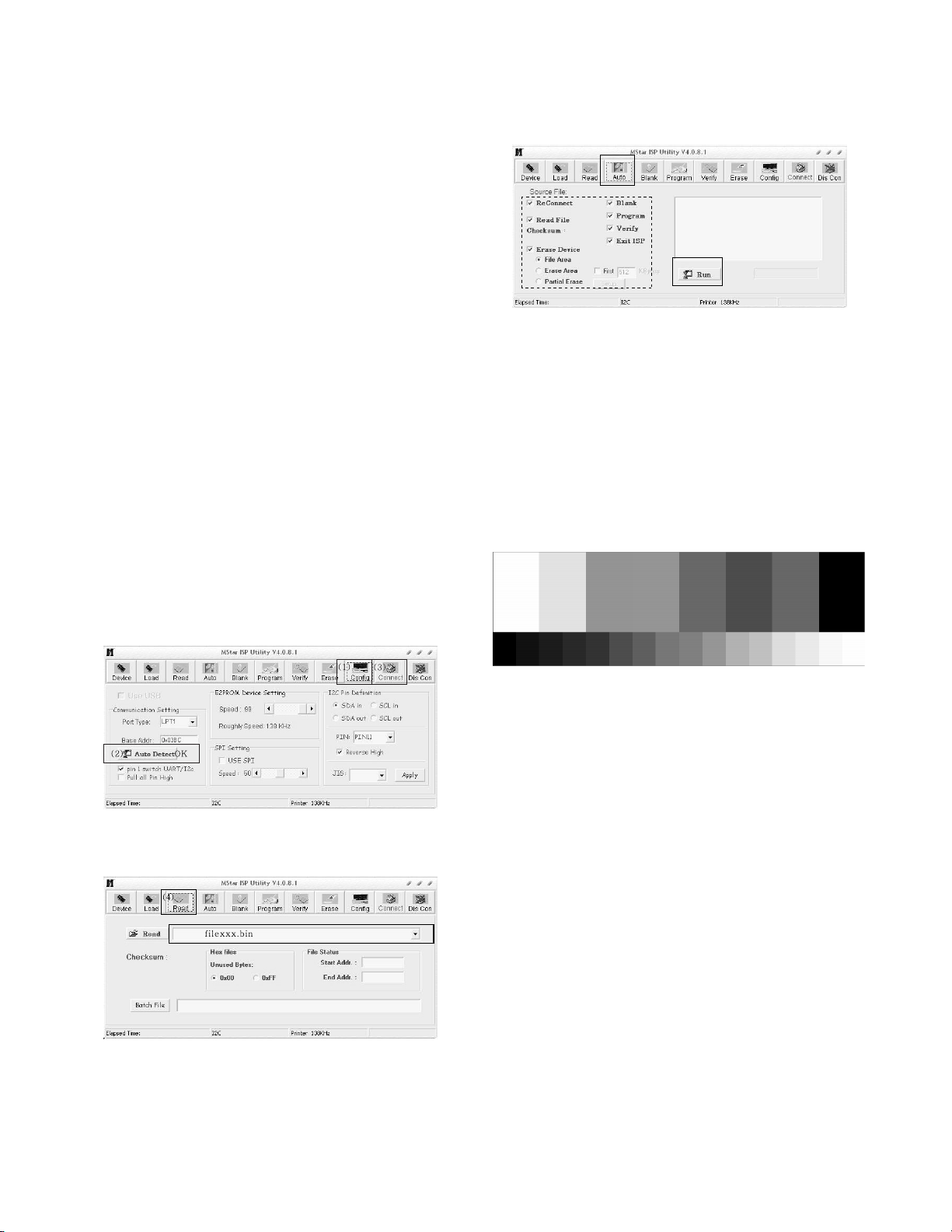
1) Execute ISP program “Mstar ISP Utility”
2) Click “Config” and set as below
3) Click “Auto Detect” and check “OK” message.
If “Error” is displayed, check connecting computer, jig, and
set again.
4) Click “Connect”.
If “Can’t” is displayed, check connecting computer, jig, and set.
5) Click “Read” tab, and then load download file(XXXX.bin) by
clicking “Read”.
6) Click “Auto” tab and set as below.
7) click “Run”.
8) After downloading, check “OK” message.
3.2. ADC Process
(1) COMPONENT input ADC
1) Component Gain/Offset Adjustment
- Convert to Component in Input-source
- Signal equipment displays
Impress Resolution 480P
MODEL : 212 in Pattern Generator
(480p Mode, Y : 100%, Pb/Pr : 100%)
PATTERN : 08 in Pattern Generator
(MSPG-925 Series)
- Adjust by commanding AUTO_COLOR_ADJUST
(0xF1) 0x00 0x02 instruction.
2) Confirmation
- We confirm whether “0x8E” address of EEPROM
“0xB4” is “0xAA” or not.
- If “0x8E” address of EEPROM “0xB4” isn’t “0xAA”, we
adjust once more.
- We can confirm the ADC values from “0x00~0x05”
addresses in a page “0xB4”.
3.3. Function Check
(1) Check display and sound
- Check Input and Signal items. (cf. work instructions)
1) TV
2) AV1 : CVBS
3) AV2 : CVBS/ S-Video
4) COMPONENT : D-terminal(D4)
5) HDMI
* Display and Sound check is executed by Remote control.
filexxx.bin
(5)
(7) .......OK
(6)
Page 8
- 8 -
4. Total Assembly line process
4.1. Adjustment Preparation
- Above 30 minutes H/run in RF no signal
4.2. Confirm color coordinate of component
(1) Set Input to COMPONENT.
(2) Input signal : 480P
Full white 216/255 gray level (85 IRE Model : 212, Pattern :
78 at MSPG925L)
(3) Set PSM : Dynamic / CSM : Cool
(4) Confirm whether x = 0.276+±0.03, y = 0.283±0.03 or not.
4.3. Confirm color coordinate of AV2
(1) Set Input to AV2
(2) Input signal : CVBS, NTSC-M
Full white 216/255 gray level (85 IRE, Model : 201, Pattern
: 78 at MSPG925L)
(3) Set PSM : Dynamic / CSM : Cool
(4) Confirm whether x = 0.276±0.03, y = 0.283±0.03 or not.
4.4. Other quality
- Confirm that each items satisfy under standard condition that
was written product spec.
- Confirm Video and Sound at each source
(1) Analog TV
- Select input Analog TV and check whether picture is
displayed or not.
(2) Terrestrial Digital TV
- Select input Terrestrial Digital TV and check whether
picture is displayed or not.
* Use ISDB-T Signal Generator(LG3802) and Stream
(Ch11, NHK1, Freq.473.143MHz) stored in the Generator.
Caution) It’s necessary to connect B-CAS CARD when you
check this source.
(3) Satellite Digital TV (BS/CS)
Select input BS satellite Digital TV and check whether
picture is displayed or not.
Caution) It’s necessary to connect B-CAS CARD when you
check this source.
(4) AV1
- Select input AV1 (CVBS) and whether picture is displayed
or not.
(5) AV2
- Select input AV2 (CVBS/S-video) and whether picture is
displayed or not
(6) COMPONENT
- Select input COMPONENT and whether picture is
displayed or not.
(7)HDMI
- Select input HDMI and whether picture is displayed or not
4.5. Power Consumption
1) Press “EYE” button on LG Adjust remocon and check
whether LED color is amber or not.
2) Press “POWER” button on LG Ajust remocon to enter
Stand-by mode.
3) Check the power consumption. (Under 1W)
4.6. HDCP setting
(High-Bandwidth Digital Contents Protection)
- Connect HDMI cable to HDMI jack.
- Input HDCP key with HDCP-key-in-program.
- HDCP key value is stored on EEPROM(AT24C64) which is
E00~F20 addresses of 0xBC~0xBE page.
- AC off/on and on HDCP button of MSPG925 and confirm
whether picture is displayed or not of using MSPG925.
- HDCP key value is different among the sets.
4.7 DDC EDID Write
1) Connect HDMI Signal Cable to HDMI Jack.
2) Write EDID DATA to EEPROM(24C02) by using DDC2B
protocol.
3) Check whether written EDID data is correct or not. (refer to
Product spec).
<DIGITAL DATA 256Byte>
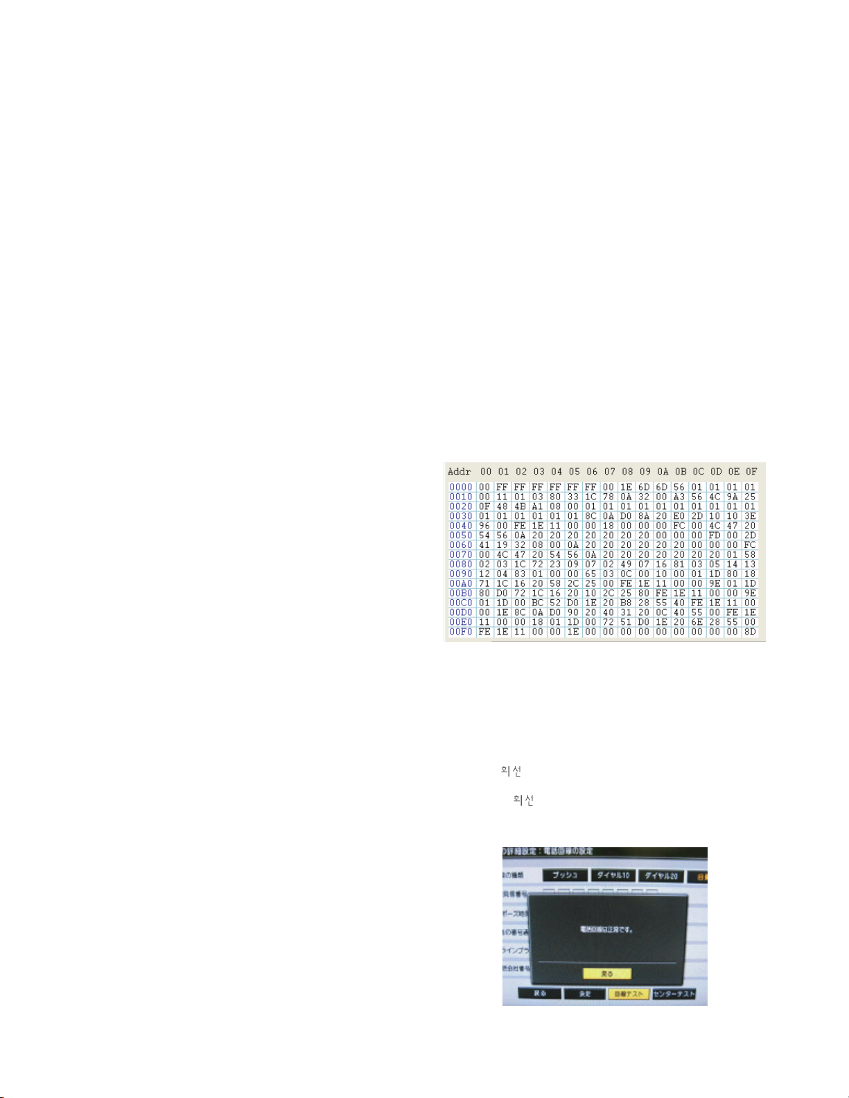
4.8. Modem Communication check
1) Connect a telephone wire between TV and Terminal
adapter (MN128mini-SV1)
2) Press “EYE” button on LG Adjust Remocon and chek
whether Power LED color is amber or not.
3) Press “MODE” button on LG Adjust Remocon and check
whether the other LED color is red or not.
4) After “
test” is progressing automatically in DTV menu,
check whether the message is displayed or not as below.
(During “
test”, color of the other LED is green.)
If the message is displayed, Modern communication test is
OK.
Page 9
4.9. Hi-POT
Confirm whether is normal or not when between power
board’s as block and GND is impacked on 1500 Vac or 2121
Vdc/1sec for one second.
(Judgment condition
: 1) Supply DC voltage -> set cut-off current to 10mA
2) Supply AC voltage -> set cut-off current to 100mA)
4.10. Insulation
After setting above condition, supply 500Vdc and then
measure the insultion resistance(Spec : above 4M ohm)
4.11. Outgoing condition Configuration
- Analog/ Digital TV Initializing
1) Press “EYE” button on LG ADJUST REMOCON.
(If Pressed “EYE” button on LG ADJUST REMOCON,
Color of Power LED will be Amber)
2) Press “IN-STOP” button on LG ADJUST REMOCON. It is
executed 3~15 procedure automatically by Software
program.(If pressed “IN-STOP” button, Color of “
” LED will be RED)
3) After Initializing is finished, the TV set turns off
automatically.
4.10. Option data setting(SVC OSD setting)
* Tool/Area option confirm.
If Tool option(17280)/Area option(0) is not, change the Tool
option(17280)/Area(0) value compulsorily.
5. Adjustment Command
5.1. Adjustment Commands(LENGTH=84)
- 9 -
TOOL OPTION 17280
AREA OPTION 0
OPTION 1 6
OPTION 2 2
OPTION 3 2
OPTION 4 0
OPTION 5 9
FACTORY ON E0 00 00 Factory mode on
FACTORY OFF E2 00 00 Factory mode off
EEPROM ALL INIT. E4 00 00 EEPROM All clear
EEPROM Read E7 00 00 EEPROM Read
EEPROM Write E8 00 data EEPROM Write by some values
COLOR SAVE (R/G/B cutoff, Drive, Contrast, Bright) EB 00 00 Color Save
H POSITION 20 00 00 – 100 They have different range each mode, FOS Adjustment.
V POSITION 30 00 00 – 100
CLOCK 90 00 00 – 100
PHASE 92 00 00 – 100
R DRIVE 16 00 00 – FF Drive adjustment
G DRIVE 18 00 00 – FF
B DRIVE 1A 00 00 – FF
R CUTOFF 80 00 00 – 7F Offset adjustment
G CUTOFF 82 00 00 – 7F
B CUTOFF 84 00 00 – 7F
BRIGHT 10 00 00 – 3F Bright adjustment
CONTRAST 12 00 00 - 64 Luminance adjustment
AUTO_COLOR_ADJUST F1 00 02 Auto COLOR Adjustment
CHANGE_COLOR_TEMP F2 00 0,1,2,3 0 : COOL, 1 : NORMAL, 2 : WARM, 3 : USER
FACTORY_DEFAULT F3 00 00 Factory mode off & II_SW is “1” & Input change to “ TV”
AUTO_INPUT CHANGE F4 00 0,1,2,4 0:ATV, 1:Video1, 2:Video2, 3:DTV, 4:D-TERMNAL, 5:HDMI
VAL DescriptionADRCMD(hex)Adjustment Contents
Page 10
- 10 -
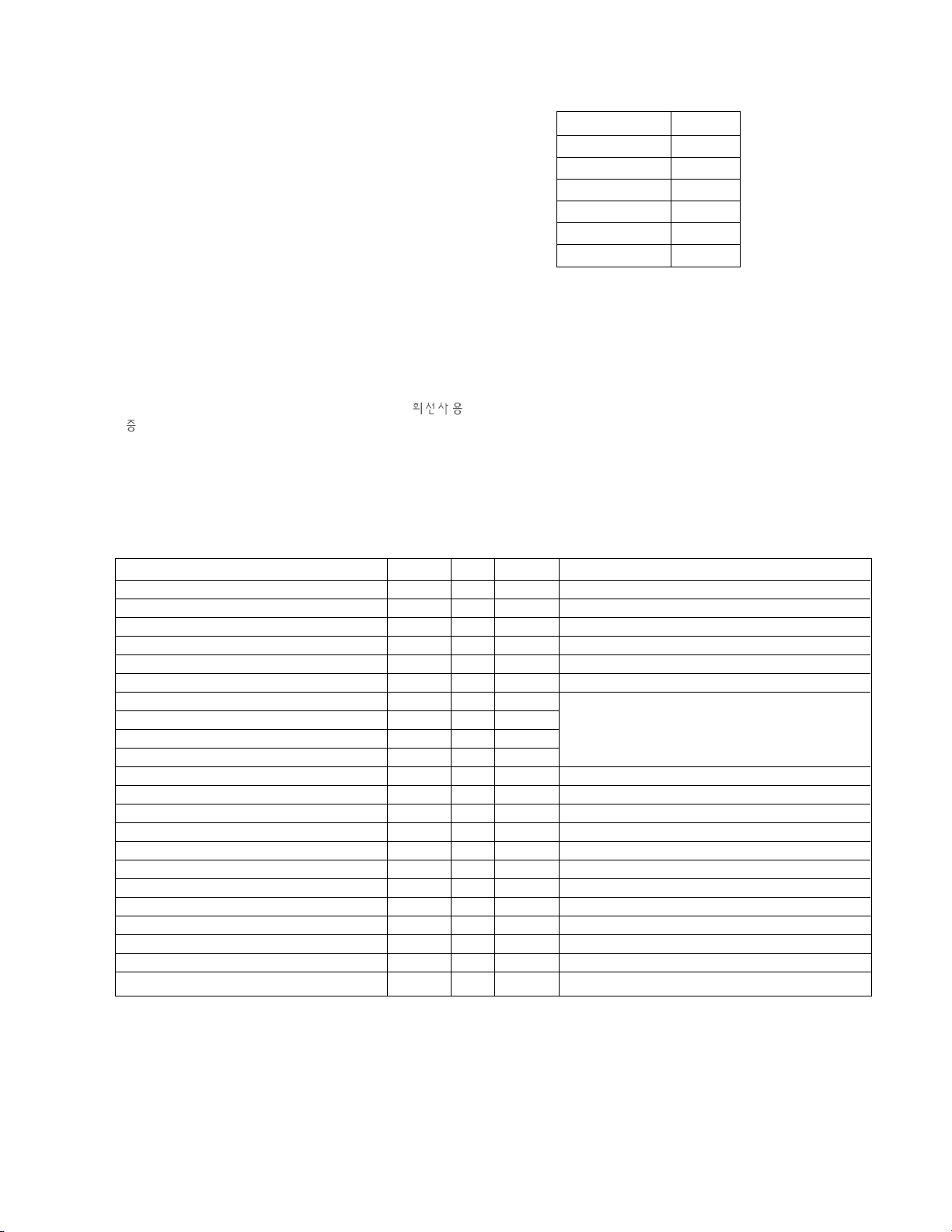
5.2 EEPROM DATA READ
(1) Signal Table
(2) Command Set
* Purpose : To read the appointment Address of E2PROM by
128(80h)-byte
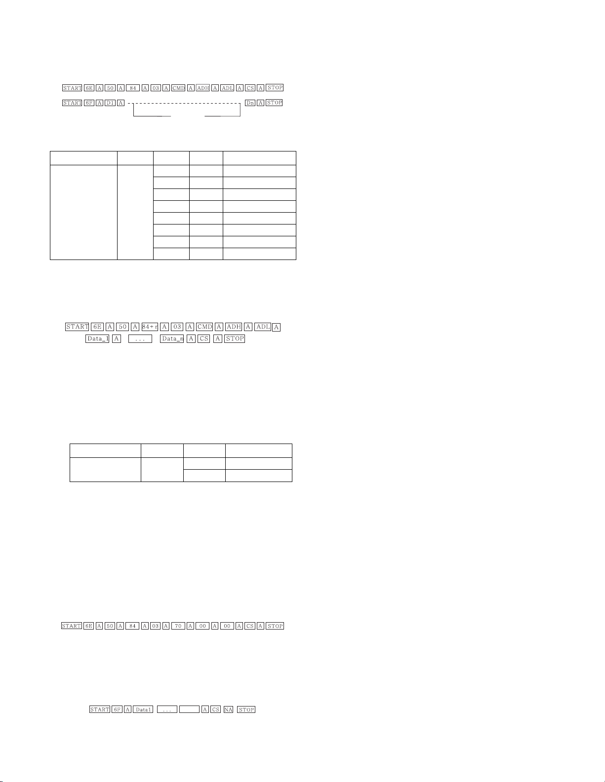
5.3. E2PROM Data Write
(1) Signal Table
LEN : 84h+Bytes
CMD : 8Eh
ADH : E
2
PROM Slave Address(A0,A2,A4,A6,A8), Not
00h(Reserved by BufferToEEPROM)
ADL : E
2
PROM Sub Address(00~FF)
Data : Write data
(2) Command Set
* Purpose
1) EDID write : 16-byte by 16-byte, 8 order (128-byte)
write(TO “00 – 7F” of “EEPROM Page A4”).
2) FOS Default write : 16-mode data (HFh, HFl, VF, STD,
HP, VP, Clk, ClkPh, PhFine) write.
3) Random Data write : write the appointment Address of
E
2
PROM.
5.4. VRAM Read
1) Send CMD(70h) to read Video RAM value from MICOM
And save its value to 128-Bytes Buffer.(Common Buffer for
the use of EDID)
2) Delay 500ms. (Time to Wait and Read Video RAM from
MICOM)
3) Be transmitted the contents of MICOM’s 128-bytes Buffer to
PC. (128th Data is the CheckSum of 127-bytes data :
That’s OK if the value of adding 128-bytes Data is Zero)
128 Bytes
Delay 100ms
Data 128
EEPROM READ E7 A0 0 0-Page 0~7F Read
80 0-Page 80~FF Read
A2 0 1-Page 0~7F Read
80 1-Page 80~FF Read
A4 0 2-Page 0~7F Read
80 2-Page 80~FF Read
A6 0 3-Page 0~7F Read
80 3-Page 80~FF Read
Adjustment contents CMD(hex) ADH(hex) ADL(hex) Details
EEPROM WRITE E8 94 16-Byte Write
84+n n-byte Write
Adjustment contents CMD(hex) ADH(hex) Details
Page 11
TROUBLE SHOOTING
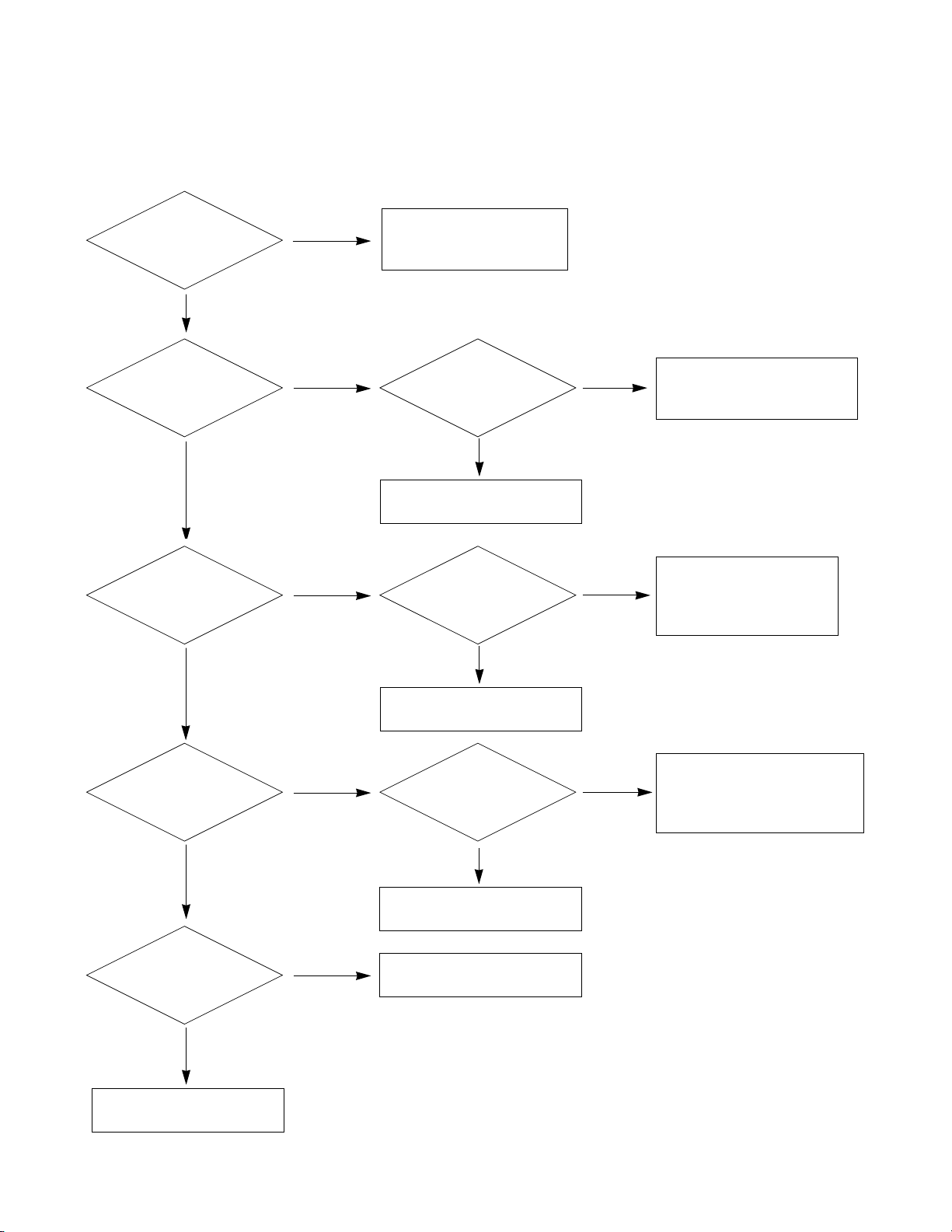
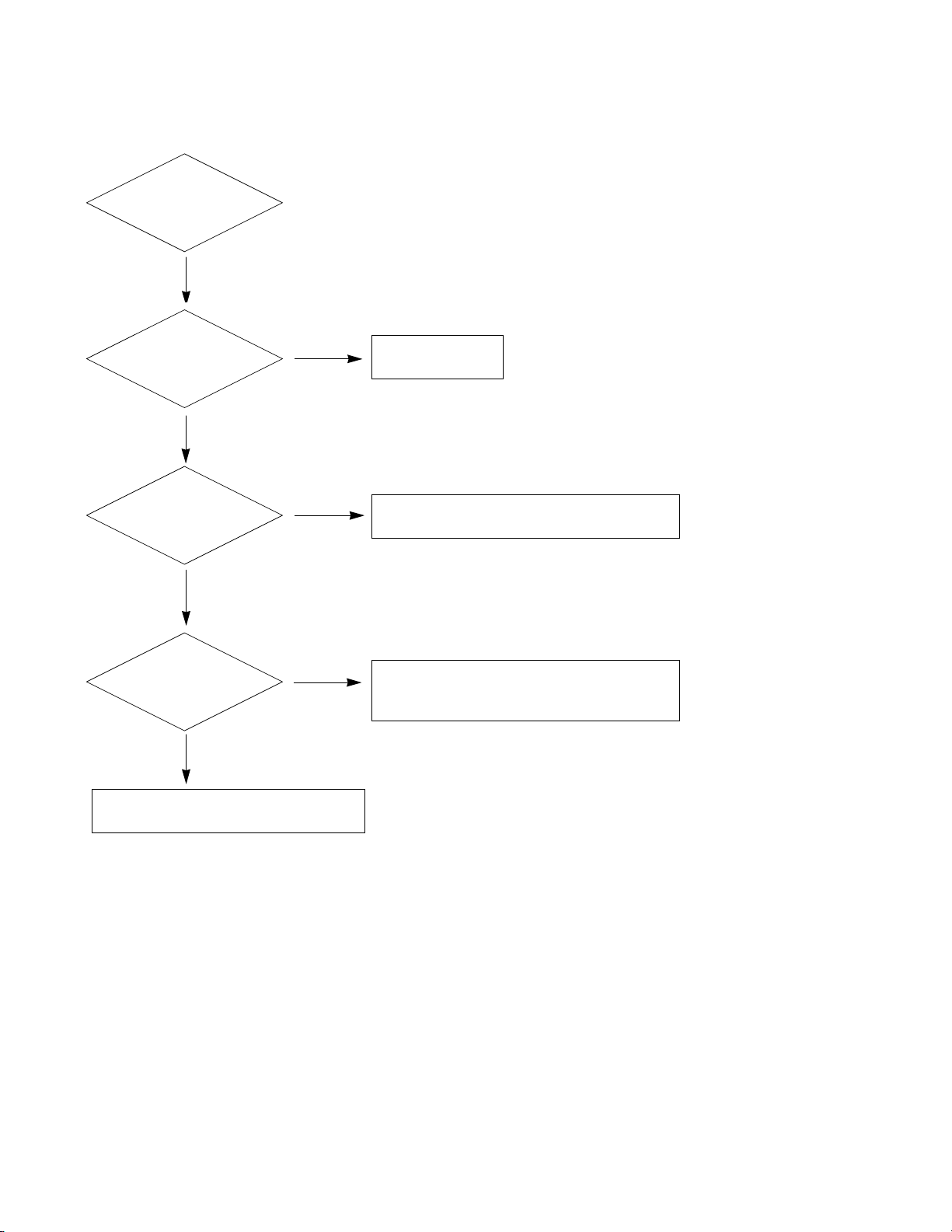
1. No Power (LED indicator off) : [A] Process
- 11 -
Check 12V or
ST_5V of Power B/D.
Fail
Pass
Check short of Main B/D
or Change Power B/D.
Check Output of
IC1000, IC1004.
Fail
Check short of
IC100, Q308.
Pass
Pass
Fail
Re-soldering or Change
defect part of IC100, Q308.
Change IC1000, IC1004.
Pass
Change IC1006, IC1005.
Check Output of
IC1006, IC1005.
Fail
Check short of
Q308, TU600, IC500.
Fail
Re-soldering or Change
defect part of Q308,
TU600, IC500.
Pass
Pass
Change IC1002, IC1003.
Change LED Assy.
Check Output of
IC1002, IC1003.
Pass
Check LED Assy.
Pass
Check P306 Connector.
Fail
Check short of
IC100, IC400.
Fail
Fail
Re-soldering or Change
defect part of IC100, IC400.
Page 12
- 12 -
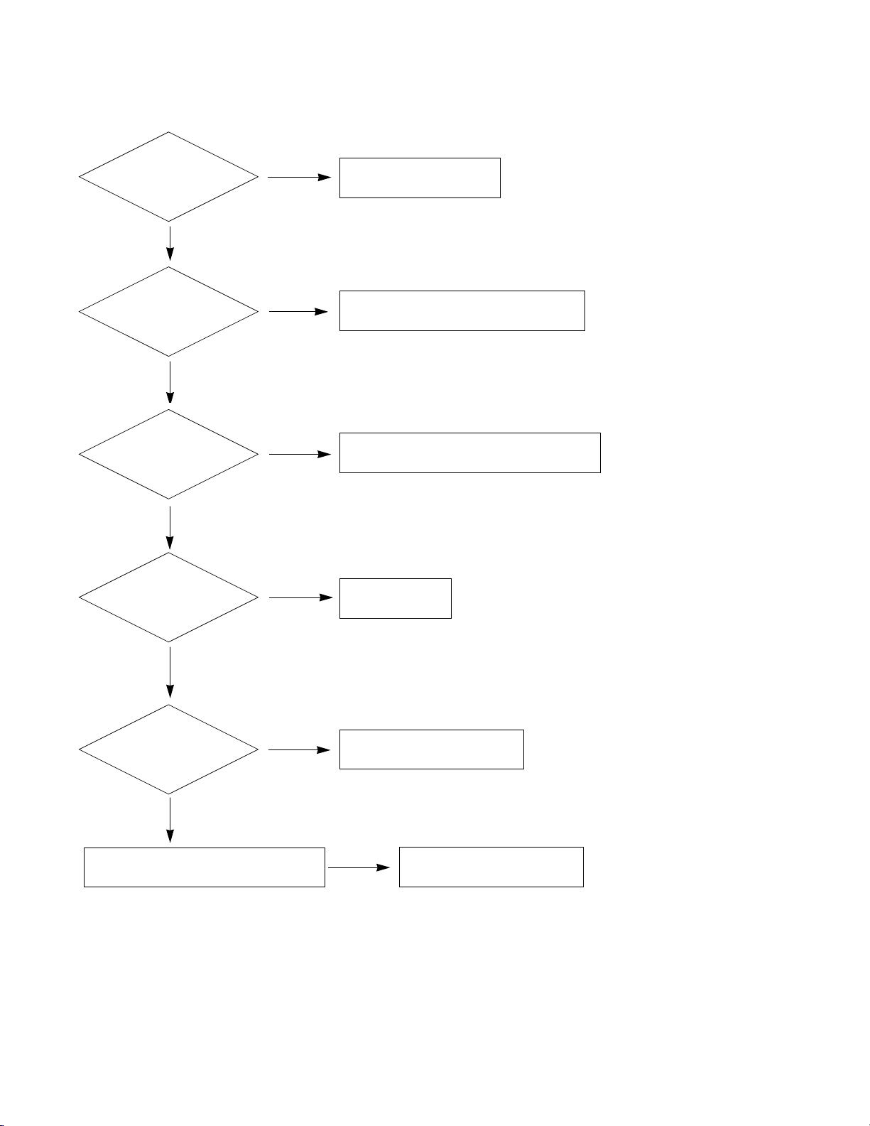
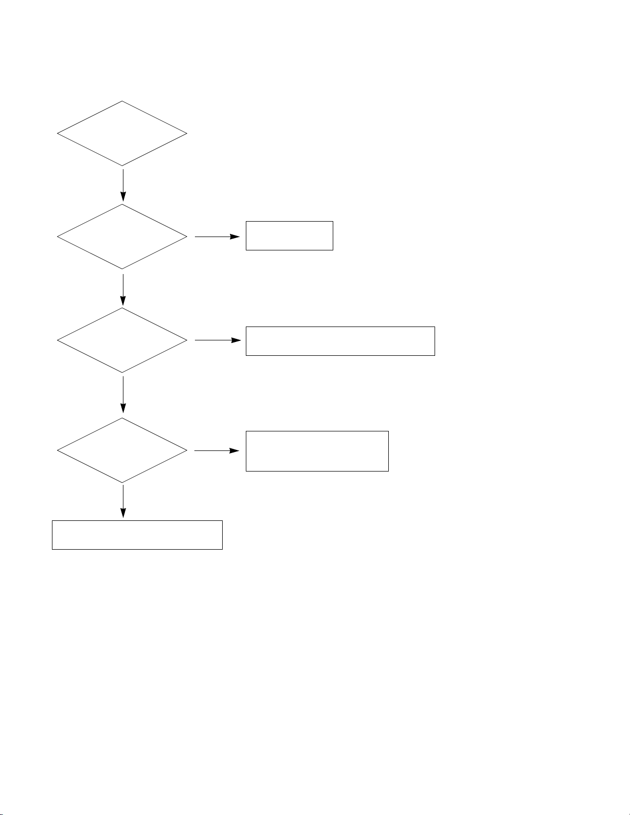
2. No RASTER : [B] Process
Check LED status
On Display Unit.
Fail
Pass
Repeat A PROCESS.
Check Panel Link
Cable or Module.
Pass
Fail
Change Panel Link Cable or Module.
Check Inverter
Connector or
inverter.
Fail
Change Inverter Connector or Inverter.
Pass
Change IC100
Check Output of
Q308.
Pass
Check the LVDS
Output of IC100
Pass
Check Input source Cable and Jack.
Fail
Change Module.
Fail
Fail
Change Q308.
Page 13
- 13 -
3. No RASTER on DTV Signal
Repeat [A,B] process
Pass
Check the input/
output of R918.
Fail
Check the P901.
Pass
Re-soldering or change the defect part.
Check the X100
Check the input/
output of R127.
Pass
Check the input/
output of IC100
Pass
Check and Change the Digital board.
Fail
Fail
Re-soldering or Change the defect part.
Page 14
- 14 -
4. No Raster on Component Signal
Repeat [A, B]
process.
Pass
Check the input/
output of R806.
Fail
Check the J801.
Pass
Re-soldering or change the
defect part, Check the X100.
Check
the input/output
of R121.
Pass
Check the
input/output of IC100.
Pass
Check input source cable and jack.
Fail
Fail
Re-soldering or Change the defect part.
Page 15

5. No Raster on HDMI Signal
6. No Raster on AV (Video,
S-Video) Signal
7. No Raster on TV(RF) Signal
- 15 -
Repeat [A, B]
process.
Pass
Check the input/
output of IC100.
Fail
Re-soldering or change the
defect part, Check the X100.
Pass
Check input source cable and jack.
Check input source cable and jack.
Repeat [A, B]
process.
Pass
Check the output
of TU600.
Pass
Pass
Fail
Check 5V of TU600.
Re-Soldering or change
the defect part.
Check the
input/output of L702,
R954, R948.
Fail
Change L702, R954,
R948.
Pass
Check input/output
of IC100.
Pass
Fail
Re-soldering of Change defect part.
Check the X100.
Page 16

8. No sound
- 16 -
Check the input
Source.
Fail
Pass
Change the source input.
Check input/Output
of IC100.
Fail
Pass
Re-soldering of Change the defect part.
Check the X110
Check the input/
output of IC500
Fail
Re-soldering or Change
the defect part.
Pass
Check the Speaker
Pass
Check the Speaker wire.
Fail
Change Speaker.
Page 17

- 17 -
WIRING DIAGRAM
Wiring Part List
6631T25026L12
6631T20010F13
EAD3850980111
6631900013B10
6631900048B9
EAD385990018
6631T20033C7
EAD385989016
5
EAD385988014
3
6631900012C2
EAD385991021
Part No.No.
2
6631T200
1
A
3
4
3
1
14
2
3
4
7 8
13
9
5
6
11
12
10
T
5
6631 22R
0
3
EAD3 399001
2
Page 18

- 18 -
Connect t o next page
Connect t o next page
Connect t o next page
Connect t o next page
BLOCK DIAGRAM
1. Digital
Page 19

- 19 -
HDMI
CVBS(AV1)
SP (R)
SP (L)
Audio
Amp
(YDA138)
LCD
Module
20LCD:AUO 20inch
23LCD:AUO 23inch
128MB
SDRAM
(HY5DU281622)
SYSTEM
EEPROM (6 4k)
Y/ C
Y/Pb/ Pr
4M bit
Serial
Flash
Memory
(
MX25L4005A)
EXT_ISP
TMDS Signal & IIC
D4
DIGITAL Bo ard Audio
SIDE AV Audio
EEPROM
(2k)
D-SUB
Tuner
TAFT-H003F
VID EO
SIF
L
R
LVDS Signal
L/ R
Scaler+Video
Decorder
(LGE9689AD-LF)
L/ R
Power Vol- Vol+ Ch- Ch+ SourcePower Vol- Vol+ Ch- Ch+ Source
LED(G)
IR
LED(R/ G)
IR receiver
Y/Pb/ Pr
DIGITAL
Board
SIDE S-VIDEO
Y&C
D4 Audio
L/ R
CVBS Audio
L/ R
SIDE CVBS(AV2)
Y&C
RS232
2. Analog
Page 20

- 20 -
300
200
LV1
550
600
601
551
120
590
591
910
920
900
930
570
560
561
580
520
521
400
531
530
581
EXPLODED VIEW
A21
A2
Page 21

- 21 -
EXPLODED VIEW PARTS LIST
No. PART NO. DESCRIPTION
120 EAB35995501
Speaker,Full Range A11 EN1227C-6710 3W 8OHM 80DB 300HZ 31 X 78.5 X 21 LUG KOREA TOPTONE
200 EAJ38281101 LCD,Module-TFT T230XW01-V3 viewing angle 160/160, TN mode(Normally White) AU OP
300 ABJ33891501 Cabinet Assembly 23LS7D-JA LJ71A 23” 23LS7D-JA Cabinet ass’y
400 ACQ33891601 Cover Assembly,Rear 23LS7D LJ71A 23” 23LS7D-JA Back cover ass’y
520 EBU38647701 Main Total Assembly 23LS7D-JA BRAND LJ71A
521 ADV33211702 Frame Assembly 23LS7D-JA LJ71A 23” METAL MAIN SHIELD ASSY
530 EBR38658101 PCB Assembly,Sub SUB T.T LJ71A 23LS7D-JA AJLWLAX CONTROL
531 MEY38698501 Knob MOLD ABS HF-350U MAIN/SMPS 6 23LS7D-JA 23” Control knob(JAPAN)
551 EBR36653604 Hand Insert PCB Assembly,Sub SUB M.I LJ71A 23LS7D-JA AJLWLAX B-CAS
551 MCK38699101 Cover MOLD HIPS 51SF 20LS7D-JA HIPS 51SF 20”” Cover,B_CAS(JAPAN)
560 EBR36698501 PCB Assembly,MPEG MDB2-J05 SUB T.T H2XLCD-H5JK MPEG BOARD FOR JAPAN MITSUMI
561 MGJ37787201 Plate,Shield PRESS SPTE 0.6T SHIELD SPTE HLS METAL, D-BOARD SHIELD
570 EBR37252602 Hand Insert PCB Assembly,Sub SUB M.I LJ71A INTERFACE_1 and INTERFACE_2
580 EAY33025102 SMPS,AC/DC LGLP 2627 HEP 90VTO264V 140W 47-63 UL/CSA/SEMKO JAPAN‚ DTV(HSL)
581 EAD38599102 Drawing,Assembly AC SOCKET AND SWITCH ASSEMBLY UL1015AWG22
590 EBR38656001 PCB Assembly,Sub SUB T.T LJ71A 2XLS7D-JA AJLWLAX IR/LED
591 MES38698301 Indicator MOLD PMMA HI-855M LED 20/23LS7D-JA PMMA 8 PHY IR LENS(JAPAN)
600 EBR36651102 Hand Insert PCB Assembly,Sub SUB M.I LJ71A 2xLS7D-JA AJLWLAX SIDE_AV
601 ABA34844001 Bracket Assembly BRACKET 20/23LS7D-JA LJ71A BRACKET, B-CAS & SIDE AV ASS’Y(JAPAN)
900 AAN32620501 Base Assembly BASE 23LS7D LA74E BASE ASSY 23”
910 ABA33891701 Bracket Assembly HINGE 20/23LS7D-JA LJ71A 20/23LS7D-JA Hinge body ass’y
920 MCK36500501 Cover,Rear MOLD ABS 380 19LS4R ABS, HF-380 19LS4R STAND BODY COVER
930 MCK30233401 Cover MOLD HIPS 51SF LS1R HIPS 51SF LS1R-holder cable management
A2 AKB33871402 Remote Controller Assembly 20/23LS7D-JA, JP D-TV, LJ71A
A21 MCK36759201 Cover MOLD ABS HF-380 MKJ339814 ABS, HF-380 TX BATTERY COVER
LV1 EAD39309201 12507HS FI-X30HL 12507HS-30 FI-X30HL 300MM
Page 22

- 22 -
C1 0CK104CK56A 0603B104K500CT 100nF 10% 50V X7R -55TO+125
C100 0CK104CK56A 0603B104K500CT 100nF 10% 50V X7R -55TO+125
C1000 0CE227WF6DC MVK8.0TP16VC220M 220uF 20% 16V 80MA -40TO+
C1001 0CK105DH56A C2012X7R105KFT 1uF 10% 25V X7R -55TO+125C
C1003 0CK105DH56A C2012X7R105KFT 1uF 10% 25V X7R -55TO+125C
C1004 0CE107WJ6DC MVK10TP35VC100M 100uF 20% 35V 310MA -40TO+
C1006 0CE337WJ6D8 MVK12.5TP35VC330M 330uF 20% 35V 480MA -40T
C1007 0CE477EJ618 KMG5.0TP35VB470M 470uF 20% 35V 547MA -55TO
C1008 0CK105DH56A C2012X7R105KFT 1uF 10% 25V X7R -55TO+125C
C1009 0CK105DH56A C2012X7R105KFT 1uF 10% 25V X7R -55TO+125C
C101 0CC200CK41A C1608C0G1H200JT 20pF 5% 50V C0G -55TO+125C
C1010 0CK474DH56A C2012X7R1E474KT 470nF 10% 25V X7R -55TO+12
C1012 0CE1072H638 WL1E107M6L011PA 100uF 20% 25V 280MA -40TO+
C1013 0CE1072H638 WL1E107M6L011PA 100uF 20% 25V 280MA -40TO+
C1016 0CK103CK56A 0603B103K500CT 10nF 10% 50V X7R -55TO+125C
C1017 0CK105CD56A C1608X7R1A105KT 1uF 10% 10V X7R -55TO+125C
C1018 0CE227WF6DC MVK8.0TP16VC220M 220uF 20% 16V 80MA -40TO+
C1019 0CE1072H638 WL1E107M6L011PA 100uF 20% 25V 280MA -40TO+
C1020 0CK104CK56A 0603B104K500CT 100nF 10% 50V X7R -55TO+125
C1022 0CE1072H638 WL1E107M6L011PA 100uF 20% 25V 280MA -40TO+
C1023 0CK104CK56A 0603B104K500CT 100nF 10% 50V X7R -55TO+125
C1025 0CK104CK56A 0603B104K500CT 100nF 10% 50V X7R -55TO+125
C1027 0CK272CK46A 0603B272J500CT 2.7nF 10% 50V X7R -55TO+125
C1028 0CE1072H638 WL1E107M6L011PA 100uF 20% 25V 280MA -40TO+
C1029 0CE1072H638 WL1E107M6L011PA 100uF 20% 25V 280MA -40TO+
C103 0CC200CK41A C1608C0G1H200JT 20pF 5% 50V C0G -55TO+125C
C1030 0CE1072H638 WL1E107M6L011PA 100uF 20% 25V 280MA -40TO+
C1031 0CK104CK56A 0603B104K500CT 100nF 10% 50V X7R -55TO+125
C1033 0CK104CK56A 0603B104K500CT 100nF 10% 50V X7R -55TO+125
C1034 0CK226FF67A EMK325BJ226MM-T 22uF 20% 16V X5R -55TO+85C
C1035 0CK104CK56A 0603B104K500CT 100nF 10% 50V X7R -55TO+125
C1039 0CK225DFK4A C2012Y5V1C225MT 2.2uF 20% 16V Y5V -30TO+85
C104 0CK104CK56A 0603B104K500CT 100nF 10% 50V X7R -55TO+125
C1040 0CE227WF6DC MVK8.0TP16VC220M 220uF 20% 16V 80MA -40TO+
C1041 0CK104CK56A 0603B104K500CT 100nF 10% 50V X7R -55TO+125
C1042 0CE2262K638 WL1H226M05011PA 22uF 20% 50V 150MA -40TO+1
C105 0CK104CK56A 0603B104K500CT 100nF 10% 50V X7R -55TO+125
C109 0CE106WFKDC MVK4.0TP16VC10M 10uF 20% 16V 16MA -40TO+10
C110 0CE106WFKDC MVK4.0TP16VC10M 10uF 20% 16V 16MA -40TO+10
C112 0CK104CK56A 0603B104K500CT 100nF 10% 50V X7R -55TO+125
C114 0CE106WFKDC MVK4.0TP16VC10M 10uF 20% 16V 16MA -40TO+10
C114 0CE475WJ6DC MVK4.0TP35VC4.7M 4.7uF 20% 35V 15MA -40TO+
C115 0CK104CK56A 0603B104K500CT 100nF 10% 50V X7R -55TO+125
C116 0CK104CK56A 0603B104K500CT 100nF 10% 50V X7R -55TO+125
C117 0CK104CK56A 0603B104K500CT 100nF 10% 50V X7R -55TO+125
C118 0CK104CK56A 0603B104K500CT 100nF 10% 50V X7R -55TO+125
C119 0CK104CK56A 0603B104K500CT 100nF 10% 50V X7R -55TO+125
C12 0CK104CK56A 0603B104K500CT 100nF 10% 50V X7R -55TO+125
C120 0CK104CK56A 0603B104K500CT 100nF 10% 50V X7R -55TO+125
C121 0CK104CK56A 0603B104K500CT 100nF 10% 50V X7R -55TO+125
C122 0CK104CK56A 0603B104K500CT 100nF 10% 50V X7R -55TO+125
C123 0CK104CK56A 0603B104K500CT 100nF 10% 50V X7R -55TO+125
C124 0CC102CK41A C1608C0G1H102JT 1nF 5% 50V C0G -55TO+125C
C125 0CK473CK56A C1608X7R1H473KT 47nF 10% 50V X7R -55TO+125
C126 0CC560CK41A C1608C0G1H560JT 56pF 5% 50V C0G -55TO+125C
C127 0CC560CK41A C1608C0G1H560JT 56pF 5% 50V C0G -55TO+125C
C128 0CK473CK56A C1608X7R1H473KT 47nF 10% 50V X7R -55TO+125
C129 0CK473CK56A C1608X7R1H473KT 47nF 10% 50V X7R -55TO+125
C13 0CE106BF618 ESM106M016T1G5C11G 10uF 20% 16V 45MA -55TO
C130 0CK473CK56A C1608X7R1H473KT 47nF 10% 50V X7R -55TO+125
C131 0CK473CK56A C1608X7R1H473KT 47nF 10% 50V X7R -55TO+125
C132 0CK473CK56A C1608X7R1H473KT 47nF 10% 50V X7R -55TO+125
C133 0CK473CK56A C1608X7R1H473KT 47nF 10% 50V X7R -55TO+125
C134 0CK473CK56A C1608X7R1H473KT 47nF 10% 50V X7R -55TO+125
C135 0CK473CK56A C1608X7R1H473KT 47nF 10% 50V X7R -55TO+125
C136 0CK473CK56A C1608X7R1H473KT 47nF 10% 50V X7R -55TO+125
C137 0CK473CK56A C1608X7R1H473KT 47nF 10% 50V X7R -55TO+125
C138 0CK473CK56A C1608X7R1H473KT 47nF 10% 50V X7R -55TO+125
C139 0CK473CK56A C1608X7R1H473KT 47nF 10% 50V X7R -55TO+125
C140 0CK473CK56A C1608X7R1H473KT 47nF 10% 50V X7R -55TO+125
C141 0CK473CK56A C1608X7R1H473KT 47nF 10% 50V X7R -55TO+125
C142 0CK473CK56A C1608X7R1H473KT 47nF 10% 50V X7R -55TO+125
C143 0CC102CK41A C1608C0G1H102JT 1nF 5% 50V C0G -55TO+125C
C144 0CK473CK56A C1608X7R1H473KT 47nF 10% 50V X7R -55TO+125
C145 0CK473CK56A C1608X7R1H473KT 47nF 10% 50V X7R -55TO+125
C146 0CK473CK56A C1608X7R1H473KT 47nF 10% 50V X7R -55TO+125
C147 0CK473CK56A C1608X7R1H473KT 47nF 10% 50V X7R -55TO+125
C148 0CK473CK56A C1608X7R1H473KT 47nF 10% 50V X7R -55TO+125
C149 0CK473CK56A C1608X7R1H473KT 47nF 10% 50V X7R -55TO+125
C150 0CK473CK56A C1608X7R1H473KT 47nF 10% 50V X7R -55TO+125
C152 0CK473CK56A C1608X7R1H473KT 47nF 10% 50V X7R -55TO+125
C153 0CK473CK56A C1608X7R1H473KT 47nF 10% 50V X7R -55TO+125
C154 0CK473CK56A C1608X7R1H473KT 47nF 10% 50V X7R -55TO+125
C155 0CK473CK56A C1608X7R1H473KT 47nF 10% 50V X7R -55TO+125
C156 0CK104CK56A 0603B104K500CT 100nF 10% 50V X7R -55TO+125
C157 0CK104CK56A 0603B104K500CT 100nF 10% 50V X7R -55TO+125
C158 0CE106WFKDC MVK4.0TP16VC10M 10uF 20% 16V 16MA -40TO+10
C159 0CK104CK56A 0603B104K500CT 100nF 10% 50V X7R -55TO+125
C160 0CK475CC94A C1608Y5V0J475ZT 4.7uF -20TO+80% 6.3V Y5V -
C161 0CK104CK56A 0603B104K500CT 100nF 10% 50V X7R -55TO+125
C162 0CK105CD56A C1608X7R1A105KT 1uF 10% 10V X7R -55TO+125C
C163 0CK225DFK4A C2012Y5V1C225MT 2.2uF 20% 16V Y5V -30TO+85
C164 0CK225DFK4A C2012Y5V1C225MT 2.2uF 20% 16V Y5V -30TO+85
C165 0CK225DFK4A C2012Y5V1C225MT 2.2uF 20% 16V Y5V -30TO+85
C166 0CK225DFK4A C2012Y5V1C225MT 2.2uF 20% 16V Y5V -30TO+85
C167 0CK225DFK4A C2012Y5V1C225MT 2.2uF 20% 16V Y5V -30TO+85
C168 0CK225DFK4A C2012Y5V1C225MT 2.2uF 20% 16V Y5V -30TO+85
C169 0CK225DFK4A C2012Y5V1C225MT 2.2uF 20% 16V Y5V -30TO+85
C170 0CK225DFK4A C2012Y5V1C225MT 2.2uF 20% 16V Y5V -30TO+85
LOC. NO. PART NO. DESCRIPTION / SPECIFICATION LOC. NO. PART NO. DESCRIPTION / SPECIFICATION
REPLACEMENT PARTS LIST
DATE: 2007. 08. 06.
CAPACITORs
Page 23

- 23 -
C171 0CK104CK56A 0603B104K500CT 100nF 10% 50V X7R -55TO+125
C172 0CK225DFK4A C2012Y5V1C225MT 2.2uF 20% 16V Y5V -30TO+85
C175 0CK104CK56A 0603B104K500CT 100nF 10% 50V X7R -55TO+125
C176 0CK103CK56A 0603B103K500CT 10nF 10% 50V X7R -55TO+125C
C177 0CK103CK56A 0603B103K500CT 10nF 10% 50V X7R -55TO+125C
C178 0CK104CK56A 0603B104K500CT 100nF 10% 50V X7R -55TO+125
C179 0CK104CK56A 0603B104K500CT 100nF 10% 50V X7R -55TO+125
C180 0CK104CK56A 0603B104K500CT 100nF 10% 50V X7R -55TO+125
C181 0CE106BF618 ESM106M016T1G5C11G 10uF 20% 16V 45MA -55TO
C182 0CK104CK56A 0603B104K500CT 100nF 10% 50V X7R -55TO+125
C183 0CK104CK56A 0603B104K500CT 100nF 10% 50V X7R -55TO+125
C184 0CK104CK56A 0603B104K500CT 100nF 10% 50V X7R -55TO+125
C185 0CK104CK56A 0603B104K500CT 100nF 10% 50V X7R -55TO+125
C186 0CK104CK56A 0603B104K500CT 100nF 10% 50V X7R -55TO+125
C187 0CK104CK56A 0603B104K500CT 100nF 10% 50V X7R -55TO+125
C188 0CK104CK56A 0603B104K500CT 100nF 10% 50V X7R -55TO+125
C189 0CK104CK56A 0603B104K500CT 100nF 10% 50V X7R -55TO+125
C190 0CC102CK41A C1608C0G1H102JT 1nF 5% 50V C0G -55TO+125C
C191 0CK104CK56A 0603B104K500CT 100nF 10% 50V X7R -55TO+125
C192 0CK104CK56A 0603B104K500CT 100nF 10% 50V X7R -55TO+125
C193 0CK104CK56A 0603B104K500CT 100nF 10% 50V X7R -55TO+125
C194 0CK104CK56A 0603B104K500CT 100nF 10% 50V X7R -55TO+125
C195 0CK104CK56A 0603B104K500CT 100nF 10% 50V X7R -55TO+125
C196 0CK104CK56A 0603B104K500CT 100nF 10% 50V X7R -55TO+125
C197 0CK104CK56A 0603B104K500CT 100nF 10% 50V X7R -55TO+125
C198 0CE106BF618 ESM106M016T1G5C11G 10uF 20% 16V 45MA -55TO
C200 0CK104CK56A 0603B104K500CT 100nF 10% 50V X7R -55TO+125
C201 0CK104CK56A 0603B104K500CT 100nF 10% 50V X7R -55TO+125
C202 0CK473CK56A C1608X7R1H473KT 47nF 10% 50V X7R -55TO+125
C3 0CE106BF618 ESM106M016T1G5C11G 10uF 20% 16V 45MA -55TO
C3000 0CC331CK41A C1608C0G1H331JT 330pF 5% 50V C0G -55TO+125
C3001 0CC331CK41A C1608C0G1H331JT 330pF 5% 50V C0G -55TO+125
C3002 0CK103CK56A 0603B103K500CT 10nF 10% 50V X7R -55TO+125C
C3003 0CK103CK56A 0603B103K500CT 10nF 10% 50V X7R -55TO+125C
C3005 0CC331CK41A C1608C0G1H331JT 330pF 5% 50V C0G -55TO+125
C3006 0CC561CK41A C1608C0G1H561JT 560pF 5% 50V C0G -55TO+125
C3007 0CC561CK41A C1608C0G1H561JT 560pF 5% 50V C0G -55TO+125
C3009 0CC331CK41A C1608C0G1H331JT 330pF 5% 50V C0G -55TO+125
C303 0CK102CK56A 0603B102K500CT 1nF 10% 50V X7R -55TO+125C
C304 0CE227EH638 KMG5.0TP25VB220M 220uF 20% 25V 277MA -55TO
C305 0CK474DH56A C2012X7R1E474KT 470nF 10% 25V X7R -55TO+12
C306 0CC102CK41A C1608C0G1H102JT 1nF 5% 50V C0G -55TO+125C
C307 0CC101CK41A C1608C0G1H101JT 100pF 5% 50V C0G -55TO+125
C308 0CC101CK41A C1608C0G1H101JT 100pF 5% 50V C0G -55TO+125
C310 0CC101CK41A C1608C0G1H101JT 100pF 5% 50V C0G -55TO+125
C311 0CC101CK41A C1608C0G1H101JT 100pF 5% 50V C0G -55TO+125
C312 0CC101CK41A C1608C0G1H101JT 100pF 5% 50V C0G -55TO+125
C313 0CC101CK41A C1608C0G1H101JT 100pF 5% 50V C0G -55TO+125
C314 0CC470CK41A C1608C0G1H470JT 47pF 5% 50V C0G -55TO+125C
C4 0CK104CK56A 0603B104K500CT 100nF 10% 50V X7R -55TO+125
C400 0CK104CK56A 0603B104K500CT 100nF 10% 50V X7R -55TO+125
C4000 0CK104CK56A 0603B104K500CT 100nF 10% 50V X7R -55TO+125
C4001 0CC470CK41A C1608C0G1H470JT 47pF 5% 50V C0G -55TO+125C
C401 0CK104CK56A 0603B104K500CT 100nF 10% 50V X7R -55TO+125
C402 0CK104CK56A 0603B104K500CT 100nF 10% 50V X7R -55TO+125
C403 0CK104CK56A 0603B104K500CT 100nF 10% 50V X7R -55TO+125
C404 0CK104CK56A 0603B104K500CT 100nF 10% 50V X7R -55TO+125
C405 0CK104CK56A 0603B104K500CT 100nF 10% 50V X7R -55TO+125
C406 0CK104CK56A 0603B104K500CT 100nF 10% 50V X7R -55TO+125
C407 0CC102CK41A C1608C0G1H102JT 1nF 5% 50V C0G -55TO+125C
C408 0CK104CK56A 0603B104K500CT 100nF 10% 50V X7R -55TO+125
C409 0CK104CK56A 0603B104K500CT 100nF 10% 50V X7R -55TO+125
C5 0CK104CK56A 0603B104K500CT 100nF 10% 50V X7R -55TO+125
C500 0CK225DH94A C2012Y5V225ZFT 2.2uF -20TO+80% 25V Y5V -30
C5000 0CN1040K949 CH UP050 F104Z-B-B Z 100nF -20TO+80% 50V Y
C5001 0CN1040K949 CH UP050 F104Z-B-B Z 100nF -20TO+80% 50V Y
C5002 0CN1040K949 CH UP050 F104Z-B-B Z 100nF -20TO+80% 50V Y
C501 0CE476WK6DC MVK8.0TP50VC47M 47uF 20% 50V 170MA -40TO+1
C502 0CK103CK56A 0603B103K500CT 10nF 10% 50V X7R -55TO+125C
C503 0CK474DK56A UMK212BJ474KG-T 470nF 10% 50V X7R -40TO+10
C504 0CK103CK56A 0603B103K500CT 10nF 10% 50V X7R -55TO+125C
C505 0CE1072H638 WL1E107M6L011PA 100uF 20% 25V 280MA -40TO+
C506 0CK105CD56A C1608X7R1A105KT 1uF 10% 10V X7R -55TO+125C
C507 0CK104CK56A 0603B104K500CT 100nF 10% 50V X7R -55TO+125
C508 0CK475EF56A C3216X7R1C475KT 4.7uF 10% 16V X7R -55TO+12
C509 0CK105CD56A C1608X7R1A105KT 1uF 10% 10V X7R -55TO+125C
C510 0CE337WH6DC MVK10TP25VC330M 330uF 20% 25V 450MA -40TO+
C511 0CK475EF56A C3216X7R1C475KT 4.7uF 10% 16V X7R -55TO+12
C512 0CC102CK41A C1608C0G1H102JT 1nF 5% 50V C0G -55TO+125C
C513 0CC102CK41A C1608C0G1H102JT 1nF 5% 50V C0G -55TO+125C
C514 0CC102CK41A C1608C0G1H102JT 1nF 5% 50V C0G -55TO+125C
C515 0CC102CK41A C1608C0G1H102JT 1nF 5% 50V C0G -55TO+125C
C516 0CK105CD56A C1608X7R1A105KT 1uF 10% 10V X7R -55TO+125C
C517 0CE337WH6DC MVK10TP25VC330M 330uF 20% 25V 450MA -40TO+
C518 0CK475EF56A C3216X7R1C475KT 4.7uF 10% 16V X7R -55TO+12
C519 0CK104CK56A 0603B104K500CT 100nF 10% 50V X7R -55TO+125
C520 0CK475EF56A C3216X7R1C475KT 4.7uF 10% 16V X7R -55TO+12
C521 0CE106BF618 ESM106M016T1G5C11G 10uF 20% 16V 45MA -55TO
C522 0CK105CD56A C1608X7R1A105KT 1uF 10% 10V X7R -55TO+125C
C523 0CK105CD56A C1608X7R1A105KT 1uF 10% 10V X7R -55TO+125C
C524 0CK105CD56A C1608X7R1A105KT 1uF 10% 10V X7R -55TO+125C
C525 0CK474DK56A UMK212BJ474KG-T 470nF 10% 50V X7R -40TO+10
C526 0CK103CK56A 0603B103K500CT 10nF 10% 50V X7R -55TO+125C
C527 0CK103CK56A 0603B103K500CT 10nF 10% 50V X7R -55TO+125C
C6 0CK104CK56A 0603B104K500CT 100nF 10% 50V X7R -55TO+125
C600 0CK103CK56A 0603B103K500CT 10nF 10% 50V X7R -55TO+125C
C602 0CK103CK56A 0603B103K500CT 10nF 10% 50V X7R -55TO+125C
C605 0CE107WF6DC MVK6.3TP16VC100M 100uF 20% 16V 110MA -40TO
C7 0CK104CK56A 0603B104K500CT 100nF 10% 50V X7R -55TO+125
C702 0CC331CK41A C1608C0G1H331JT 330pF 5% 50V C0G -55TO+125
C703 0CC331CK41A C1608C0G1H331JT 330pF 5% 50V C0G -55TO+125
C705 0CC561CK41A C1608C0G1H561JT 560pF 5% 50V C0G -55TO+125
C706 0CC561CK41A C1608C0G1H561JT 560pF 5% 50V C0G -55TO+125
C708 0CC331CK41A C1608C0G1H331JT 330pF 5% 50V C0G -55TO+125
C709 0CK104CK56A 0603B104K500CT 100nF 10% 50V X7R -55TO+125
C710 0CK475DD56A C2012X7R1A475KT 4.7uF 10% 10V X7R -55TO+12
C8 0CK104CK56A 0603B104K500CT 100nF 10% 50V X7R -55TO+125
C800 0CC102CK41A C1608C0G1H102JT 1nF 5% 50V C0G -55TO+125C
C801 0CC102CK41A C1608C0G1H102JT 1nF 5% 50V C0G -55TO+125C
C901 0CK104CK56A 0603B104K500CT 100nF 10% 50V X7R -55TO+125
LOC. NO. PART NO. DESCRIPTION / SPECIFICATION LOC. NO. PART NO. DESCRIPTION / SPECIFICATION
Page 24

- 24 -
C910 0CK103CK56A 0603B103K500CT 10nF 10% 50V X7R -55TO+125C
D1 0DSON00138A MMBD301LT1G 600MV 30V - - 1.5pF 200MW SOT2
D100 0DS181009AA KDS181 1.2V 85V 300MA 2A 4NSEC 150MW SOT23
D1000 0DS181009AA KDS181 1.2V 85V 300MA 2A 4NSEC 150MW SOT23
D1002 0DR340009AA MBRS340 525MV 40V 4A 0SEC 0F 0W DO214 R/TP
D1003 0DR140059DA 1N4005TB52 600V 1V 5UA 30A - DO41 TP 2P 1
D1004 0DR140059DA 1N4005TB52 600V 1V 5UA 30A - DO41 TP 2P 1
D101 0DS181009AA KDS181 1.2V 85V 300MA 2A 4NSEC 150MW SOT23
D500 0DS181009AA KDS181 1.2V 85V 300MA 2A 4NSEC 150MW SOT23
D501 0DS181009AA KDS181 1.2V 85V 300MA 2A 4NSEC 150MW SOT23
D502 0DS181009AA KDS181 1.2V 85V 300MA 2A 4NSEC 150MW SOT23
D503 0DD184009AA KDS184 KDS184 TP KEC - 85V - - - 300MA KEC
D700 0DSON00138A MMBD301LT1G 600MV 30V - - 1.5pF 200MW SOT2
D701 0DD184009AA KDS184 KDS184 TP KEC - 85V - - - 300MA KEC
ZD1 0DZ120009CF UDZ 12B 12V 11.74TO12.24V 30OHM 200MW SOD3
ZD3000 0DZ560009DA UDZS5.6B 5.6V 5.49TO5.73V 60OHM 200MW SOD3
ZD3001 0DZ560009DA UDZS5.6B 5.6V 5.49TO5.73V 60OHM 200MW SOD3
ZD3002 0DZ560009DA UDZS5.6B 5.6V 5.49TO5.73V 60OHM 200MW SOD3
ZD3003 0DZ560009DA UDZS5.6B 5.6V 5.49TO5.73V 60OHM 200MW SOD3
ZD3005 0DZ560009DA UDZS5.6B 5.6V 5.49TO5.73V 60OHM 200MW SOD3
ZD3006 0DZ560009DA UDZS5.6B 5.6V 5.49TO5.73V 60OHM 200MW SOD3
ZD3007 0DZ560009DA UDZS5.6B 5.6V 5.49TO5.73V 60OHM 200MW SOD3
ZD3008 0DZ560009DA UDZS5.6B 5.6V 5.49TO5.73V 60OHM 200MW SOD3
ZD3009 0DZ560009DA UDZS5.6B 5.6V 5.49TO5.73V 60OHM 200MW SOD3
ZD3010 0DZ560009DA UDZS5.6B 5.6V 5.49TO5.73V 60OHM 200MW SOD3
ZD3011 0DZ560009DA UDZS5.6B 5.6V 5.49TO5.73V 60OHM 200MW SOD3
ZD4000 0DZ560009DA UDZS5.6B 5.6V 5.49TO5.73V 60OHM 200MW SOD3
ZD4001 0DZ560009DA UDZS5.6B 5.6V 5.49TO5.73V 60OHM 200MW SOD3
ZD4002 0DZ560009DA UDZS5.6B 5.6V 5.49TO5.73V 60OHM 200MW SOD3
ZD4003 0DZ560009DA UDZS5.6B 5.6V 5.49TO5.73V 60OHM 200MW SOD3
ZD4004 0DZ560009DA UDZS5.6B 5.6V 5.49TO5.73V 60OHM 200MW SOD3
ZD5000 0DZ560009CF MTZJ5.6B 5.6V 5.45TO5.73V 40OHM 500MW DO34
ZD5001 0DZ560009CF MTZJ5.6B 5.6V 5.45TO5.73V 40OHM 500MW DO34
ZD5002 0DZ560009CF MTZJ5.6B 5.6V 5.45TO5.73V 40OHM 500MW DO34
ZD700 0DZ560009DA UDZS5.6B 5.6V 5.49TO5.73V 60OHM 200MW SOD3
ZD701 0DZ560009DA UDZS5.6B 5.6V 5.49TO5.73V 60OHM 200MW SOD3
ZD702 0DZ560009DA UDZS5.6B 5.6V 5.49TO5.73V 60OHM 200MW SOD3
ZD703 0DZ560009DA UDZS5.6B 5.6V 5.49TO5.73V 60OHM 200MW SOD3
ZD704 0DZ560009DA UDZS5.6B 5.6V 5.49TO5.73V 60OHM 200MW SOD3
ZD800 0DZ560009DA UDZS5.6B 5.6V 5.49TO5.73V 60OHM 200MW SOD3
ZD801 0DZ560009DA UDZS5.6B 5.6V 5.49TO5.73V 60OHM 200MW SOD3
ZD802 0DZ560009DA UDZS5.6B 5.6V 5.49TO5.73V 60OHM 200MW SOD3
ZD803 0DZ560009DA UDZS5.6B 5.6V 5.49TO5.73V 60OHM 200MW SOD3
ZD804 0DZ560009DA UDZS5.6B 5.6V 5.49TO5.73V 60OHM 200MW SOD3
ZD805 0DZ560009DA UDZS5.6B 5.6V 5.49TO5.73V 60OHM 200MW SOD3
ZD806 0DZ560009DA UDZS5.6B 5.6V 5.49TO5.73V 60OHM 200MW SOD3
ZD807 0DZ560009DA UDZS5.6B 5.6V 5.49TO5.73V 60OHM 200MW SOD3
ZD808 0DZ560009DA UDZS5.6B 5.6V 5.49TO5.73V 60OHM 200MW SOD3
ZD901 0DZ560009GB BZT52C5V6S-(F) 5.6V 5.2TO6V 40OHM 200MW SO
ZD906 0DZ560009GB BZT52C5V6S-(F) 5.6V 5.2TO6V 40OHM 200MW SO
ZD908 0DZ560009GB BZT52C5V6S-(F) 5.6V 5.2TO6V 40OHM 200MW SO
ZD909 0DZ560009GB BZT52C5V6S-(F) 5.6V 5.2TO6V 40OHM 200MW SO
IC1 0IPRPPH024A TDA8024T 2.7TO6.5V 1.5mA 2.2TO3.2MHZ SO R/
IC100 EAN33715803 LGE9689AD-LF 300MVTO3.6V,300MVTO2.75V,300M
IC1000 0IMCRKE006B KIA278R33PI 4TO10V 3.3V 1.5W TO200IS ST 4P
IC1002 0IPMG00107A AZ1117H-2.5TR/E1 15V 2.5V 0W SOT223 R/TP 3
IC1003 0IPMGRH001G BA33BC0FP-E2 4.3TO16V 3.3V 1.2W TO252 ST 3
IC1004 0IPMG78346A AZ1085S-ADJTR/E1 12V - - TO263 R/TP 3P AD
IC1005 0ISS780500H KA78M05RTM 7TO20V 5V - DPAK R/TP 3P FAIRC
IC1006 0IMCRMZ001A MP1583DN-Z,LF 4.75TO23V 21V 0W SOIC R/TP 8
IC103 0IMMRAL026C AT24C64AN-10SU-2.7 64KBIT 8192x8bit 2.7VTO
IC400 EAN32205201 HY5DU281622FTP-5 128MBIT 8 x 16bit 2.3VTO2
IC500 EAN33643401 YDA138-EZ(D-3) 9TO13.5V 7mV 0.02% 10W 1.45
IC701 0IMMR00014A M24C02-RMN6TP 2KBIT 256X8BIT 1.8VTO5.5V 10
IC901 0ISTL00031A MC74HC4066ADR2G MC74HC4066ADR2G,LF ON SEMI
Q1001 0TR387500AA 2SC3875S(ALY) NPN 5V 60V 50V 150MA 100NA 7
Q1002 0TR387500AA 2SC3875S(ALY) NPN 5V 60V 50V 150MA 100NA 7
Q1003 0TR387500AA 2SC3875S(ALY) NPN 5V 60V 50V 150MA 100NA 7
Q1005 EBK32753101 SI4925BDY P-CHANNEL MOSFET -30V +-20 -7.1A
Q302 0TR387500AA 2SC3875S(ALY) NPN 5V 60V 50V 150MA 100NA 7
Q304 0TR390609FA KST3906-MTF PNP -5V -40V -40V -0.2A -0.000
Q305 0TR390609FA KST3906-MTF PNP -5V -40V -40V -0.2A -0.000
Q306 0TR390609FA KST3906-MTF PNP -5V -40V -40V -0.2A -0.000
Q307 0TR390609FA KST3906-MTF PNP -5V -40V -40V -0.2A -0.000
Q308 0TFFC80009A FDC6326L N/P-CHANNEL 20V -20V +-8V 1.8A -1
Q500 0TR150400BA 2SA1504S(ASY) PNP -5V -50V -50V -0.15A -0.
Q501 0TR387500AA 2SC3875S(ALY) NPN 5V 60V 50V 150MA 100NA 7
Q602 0TR387500AA 2SC3875S(ALY) NPN 5V 60V 50V 150MA 100NA 7
Q603 0TR150400BA 2SA1504S(ASY) PNP -5V -50V -50V -0.15A -0.
Q604 0TR150400BA 2SA1504S(ASY) PNP -5V -50V -50V -0.15A -0.
Q700 0TR387500AA 2SC3875S(ALY) NPN 5V 60V 50V 150MA 100NA 7
Q900 0TR390409AE KST3904 NPN 6V 60V 40V 200MA 50NA 100TO300
R1 0RJ1002D677 MCR03EZPJ103 10KOHM 5% 1/10W 1608 R/TP
R1001 0RJ1000D677 MCR03EZPJ101 100OHM 5% 1/10W 1608 R/TP
R1002 0RJ0000D677 MCR03EZPJ000 0OHM 5% 1/10W 1608 R/TP
R1005 0RJ1001D677 MCR03EZPJ102 1KOHM 5% 1/10W 1608 R/TP
R1011 0RJ1002D677 MCR03EZPJ103 10KOHM 5% 1/10W 1608 R/TP
R1013 0RJ4701D677 MCR03EZPJ472 4.7KOHM 5% 1/10W 1608 R/TP
R1014 0RJ1002D677 MCR03EZPJ103 10KOHM 5% 1/10W 1608 R/TP
R1015 0RJ1001D677 MCR03EZPJ102 1KOHM 5% 1/10W 1608 R/TP
R1018 0RJ1001D677 MCR03EZPJ102 1KOHM 5% 1/10W 1608 R/TP
R1019 0RJ1002D677 MCR03EZPJ103 10KOHM 5% 1/10W 1608 R/TP
R102 0RJ1004D477 MCR03EZPF105 1MOHM 1% 1/10W 1608 R/TP
R1020 0RH0000D622 MCR10EZHJ000 0OHM 5% 1/8W 2012 R/TP
R1022 0RJ1002D677 MCR03EZPJ103 10KOHM 5% 1/10W 1608 R/TP
R1023 0RJ2202D677 MCR03EZPJ223 22KOHM 5% 1/10W 1608 R/TP
R1028 0RJ1002D677 MCR03EZPJ103 10KOHM 5% 1/10W 1608 R/TP
R1029 0RJ6801D477 MCR03EZPF682 6.8KOHM 1% 1/10W 1608 R/TP
R1031 0RJ0000D677 MCR03EZPJ000 0OHM 5% 1/10W 1608 R/TP
LOC. NO. PART NO. DESCRIPTION / SPECIFICATION LOC. NO. PART NO. DESCRIPTION / SPECIFICATION
ICs
TRANSISTORs & FETs
DIODEs
RESISTORs
Page 25

- 25 -
R1032 0RH0000D622 MCR10EZHJ000 0OHM 5% 1/8W 2012 R/TP
R1034 0RJ1002D677 MCR03EZPJ103 10KOHM 5% 1/10W 1608 R/TP
R1036 0RJ2702D477 MCR03EZPF273 27KOHM 1% 1/10W 1608 R/TP
R1037 0RX0332K607 RSD02T3J33R0 33OHM 5% 2W 12.0X4.0MM
R1038 0RX0332K607 RSD02T3J33R0 33OHM 5% 2W 12.0X4.0MM
R1039 0RJ0000D677 MCR03EZPJ000 0OHM 5% 1/10W 1608 R/TP
R1040 0RJ1500D477 MCR03EZPF151 150OHM 1% 1/10W 1608 R/TP
R1041 0RJ0752D477 MCR03EZPF750 75OHM 1% 1/10W 1608 R/TP
R105 0RJ0000D677 MCR03EZPJ000 0OHM 5% 1/10W 1608 R/TP
R107 0RJ3302D677 MCR03EZPJ333 33KOHM 5% 1/10W 1608 R/TP
R108 0RJ1000D677 MCR03EZPJ101 100OHM 5% 1/10W 1608 R/TP
R109 0RJ4700D677 MCR03EZPJ471 470OHM 5% 1/10W 1608 R/TP
R11 0RJ0000D677 MCR03EZPJ000 0OHM 5% 1/10W 1608 R/TP
R110 0RJ0472D677 MCR03EZPJ470 47OHM 5% 1/10W 1608 R/TP
R111 0RJ0472D677 MCR03EZPJ470 47OHM 5% 1/10W 1608 R/TP
R112 0RJ0472D677 MCR03EZPJ470 47OHM 5% 1/10W 1608 R/TP
R113 0RJ0472D677 MCR03EZPJ470 47OHM 5% 1/10W 1608 R/TP
R114 0RJ0472D677 MCR03EZPJ470 47OHM 5% 1/10W 1608 R/TP
R115 0RJ0472D677 MCR03EZPJ470 47OHM 5% 1/10W 1608 R/TP
R116 0RJ0472D677 MCR03EZPJ470 47OHM 5% 1/10W 1608 R/TP
R117 0RJ0472D677 MCR03EZPJ470 47OHM 5% 1/10W 1608 R/TP
R118 0RJ0472D677 MCR03EZPJ470 47OHM 5% 1/10W 1608 R/TP
R119 0RJ0472D677 MCR03EZPJ470 47OHM 5% 1/10W 1608 R/TP
R120 0RJ0472D677 MCR03EZPJ470 47OHM 5% 1/10W 1608 R/TP
R121 0RJ0472D677 MCR03EZPJ470 47OHM 5% 1/10W 1608 R/TP
R122 0RJ0472D677 MCR03EZPJ470 47OHM 5% 1/10W 1608 R/TP
R123 0RJ0472D677 MCR03EZPJ470 47OHM 5% 1/10W 1608 R/TP
R124 0RJ0472D677 MCR03EZPJ470 47OHM 5% 1/10W 1608 R/TP
R125 0RJ0472D677 MCR03EZPJ470 47OHM 5% 1/10W 1608 R/TP
R126 0RJ4700D677 MCR03EZPJ471 470OHM 5% 1/10W 1608 R/TP
R127 0RJ0472D677 MCR03EZPJ470 47OHM 5% 1/10W 1608 R/TP
R128 0RJ0472D677 MCR03EZPJ470 47OHM 5% 1/10W 1608 R/TP
R129 0RJ0472D677 MCR03EZPJ470 47OHM 5% 1/10W 1608 R/TP
R13 0RJ0000D677 MCR03EZPJ000 0OHM 5% 1/10W 1608 R/TP
R130 0RJ0472D677 MCR03EZPJ470 47OHM 5% 1/10W 1608 R/TP
R131 0RJ0472D677 MCR03EZPJ470 47OHM 5% 1/10W 1608 R/TP
R132 0RJ0472D677 MCR03EZPJ470 47OHM 5% 1/10W 1608 R/TP
R133 0RJ0472D677 MCR03EZPJ470 47OHM 5% 1/10W 1608 R/TP
R135 0RJ0472D677 MCR03EZPJ470 47OHM 5% 1/10W 1608 R/TP
R136 0RJ0472D677 MCR03EZPJ470 47OHM 5% 1/10W 1608 R/TP
R137 0RJ0472D677 MCR03EZPJ470 47OHM 5% 1/10W 1608 R/TP
R139 0RJ0222D677 MCR03EZPJ220 22OHM 5% 1/10W 1608 R/TP
R14 0RJ1002D677 MCR03EZPJ103 10KOHM 5% 1/10W 1608 R/TP
R140 0RJ0222D677 MCR03EZPJ220 22OHM 5% 1/10W 1608 R/TP
R141 0RJ3900D677 MCR03EZPJ391 390OHM 5% 1/10W 1608 R/TP
R142 0RJ1000D677 MCR03EZPJ101 100OHM 5% 1/10W 1608 R/TP
R143 0RJ0000D677 MCR03EZPJ000 0OHM 5% 1/10W 1608 R/TP
R144 0RJ1000D677 MCR03EZPJ101 100OHM 5% 1/10W 1608 R/TP
R145 0RJ1000D677 MCR03EZPJ101 100OHM 5% 1/10W 1608 R/TP
R147 0RJ1000D677 MCR03EZPJ101 100OHM 5% 1/10W 1608 R/TP
R148 0RJ1000D677 MCR03EZPJ101 100OHM 5% 1/10W 1608 R/TP
R149 0RJ0000D677 MCR03EZPJ000 0OHM 5% 1/10W 1608 R/TP
R15 0RJ0000D677 MCR03EZPJ000 0OHM 5% 1/10W 1608 R/TP
R150 0RJ0332D677 MCR03EZPJ330 33OHM 5% 1/10W 1608 R/TP
R152 0RJ0332D677 MCR03EZPJ330 33OHM 5% 1/10W 1608 R/TP
R159 0RJ1000D677 MCR03EZPJ101 100OHM 5% 1/10W 1608 R/TP
R16 0RJ0000D677 MCR03EZPJ000 0OHM 5% 1/10W 1608 R/TP
R160 0RJ1000D677 MCR03EZPJ101 100OHM 5% 1/10W 1608 R/TP
R161 0RJ1000D677 MCR03EZPJ101 100OHM 5% 1/10W 1608 R/TP
R162 0RJ1000D677 MCR03EZPJ101 100OHM 5% 1/10W 1608 R/TP
R164 0RJ2202D677 MCR03EZPJ223 22KOHM 5% 1/10W 1608 R/TP
R165 0RJ2202D677 MCR03EZPJ223 22KOHM 5% 1/10W 1608 R/TP
R166 0RJ1002D677 MCR03EZPJ103 10KOHM 5% 1/10W 1608 R/TP
R171 0RJ1001D677 MCR03EZPJ102 1KOHM 5% 1/10W 1608 R/TP
R172 0RJ0000D677 MCR03EZPJ000 0OHM 5% 1/10W 1608 R/TP
R175 0RJ1001D677 MCR03EZPJ102 1KOHM 5% 1/10W 1608 R/TP
R176 0RJ1000D677 MCR03EZPJ101 100OHM 5% 1/10W 1608 R/TP
R177 0RJ1000D677 MCR03EZPJ101 100OHM 5% 1/10W 1608 R/TP
R178 0RJ1000D677 MCR03EZPJ101 100OHM 5% 1/10W 1608 R/TP
R179 0RJ1000D677 MCR03EZPJ101 100OHM 5% 1/10W 1608 R/TP
R180 0RJ0332D677 MCR03EZPJ330 33OHM 5% 1/10W 1608 R/TP
R181 0RJ1002D677 MCR03EZPJ103 10KOHM 5% 1/10W 1608 R/TP
R182 0RJ1002D677 MCR03EZPJ103 10KOHM 5% 1/10W 1608 R/TP
R183 0RJ1000D677 MCR03EZPJ101 100OHM 5% 1/10W 1608 R/TP
R184 0RJ1000D677 MCR03EZPJ101 100OHM 5% 1/10W 1608 R/TP
R185 0RJ1000D677 MCR03EZPJ101 100OHM 5% 1/10W 1608 R/TP
R186 0RJ1000D677 MCR03EZPJ101 100OHM 5% 1/10W 1608 R/TP
R187 0RJ0332D677 MCR03EZPJ330 33OHM 5% 1/10W 1608 R/TP
R188 0RJ1000D677 MCR03EZPJ101 100OHM 5% 1/10W 1608 R/TP
R189 0RJ0332D677 MCR03EZPJ330 33OHM 5% 1/10W 1608 R/TP
R191 0RJ1000D677 MCR03EZPJ101 100OHM 5% 1/10W 1608 R/TP
R192 0RJ1000D677 MCR03EZPJ101 100OHM 5% 1/10W 1608 R/TP
R193 0RJ1000D677 MCR03EZPJ101 100OHM 5% 1/10W 1608 R/TP
R194 0RJ1000D677 MCR03EZPJ101 100OHM 5% 1/10W 1608 R/TP
R199 0RJ1000D677 MCR03EZPJ101 100OHM 5% 1/10W 1608 R/TP
R2 0RJ1002D677 MCR03EZPJ103 10KOHM 5% 1/10W 1608 R/TP
R202 0RJ0332D677 MCR03EZPJ330 33OHM 5% 1/10W 1608 R/TP
R203 0RJ0332D677 MCR03EZPJ330 33OHM 5% 1/10W 1608 R/TP
R204 0RJ0332D677 MCR03EZPJ330 33OHM 5% 1/10W 1608 R/TP
R205 0RJ0332D677 MCR03EZPJ330 33OHM 5% 1/10W 1608 R/TP
R206 0RJ0332D677 MCR03EZPJ330 33OHM 5% 1/10W 1608 R/TP
R207 0RJ0332D677 MCR03EZPJ330 33OHM 5% 1/10W 1608 R/TP
R208 0RJ0332D677 MCR03EZPJ330 33OHM 5% 1/10W 1608 R/TP
R210 0RJ3301D677 MCR03EZPJ332 3.3KOHM 5% 1/10W 1608 R/TP
R211 0RJ0332D677 MCR03EZPJ330 33OHM 5% 1/10W 1608 R/TP
R212 0RJ0332D677 MCR03EZPJ330 33OHM 5% 1/10W 1608 R/TP
R213 0RJ0332D677 MCR03EZPJ330 33OHM 5% 1/10W 1608 R/TP
R214 0RJ0332D677 MCR03EZPJ330 33OHM 5% 1/10W 1608 R/TP
R215 0RJ0332D677 MCR03EZPJ330 33OHM 5% 1/10W 1608 R/TP
R216 0RJ0332D677 MCR03EZPJ330 33OHM 5% 1/10W 1608 R/TP
R217 0RJ3301D677 MCR03EZPJ332 3.3KOHM 5% 1/10W 1608 R/TP
R218 0RJ3301D677 MCR03EZPJ332 3.3KOHM 5% 1/10W 1608 R/TP
R219 0RJ0000D677 MCR03EZPJ000 0OHM 5% 1/10W 1608 R/TP
R220 0RJ0000D677 MCR03EZPJ000 0OHM 5% 1/10W 1608 R/TP
R221 0RJ3301D677 MCR03EZPJ332 3.3KOHM 5% 1/10W 1608 R/TP
R222 0RJ3301D677 MCR03EZPJ332 3.3KOHM 5% 1/10W 1608 R/TP
R223 0RJ1000D677 MCR03EZPJ101 100OHM 5% 1/10W 1608 R/TP
R224 0RJ1000D677 MCR03EZPJ101 100OHM 5% 1/10W 1608 R/TP
R226 0RJ1002D677 MCR03EZPJ103 10KOHM 5% 1/10W 1608 R/TP
R227 0RJ3301D677 MCR03EZPJ332 3.3KOHM 5% 1/10W 1608 R/TP
LOC. NO. PART NO. DESCRIPTION / SPECIFICATION LOC. NO. PART NO. DESCRIPTION / SPECIFICATION
Page 26

- 26 -
R228 0RJ1002D677 MCR03EZPJ103 10KOHM 5% 1/10W 1608 R/TP
R229 0RJ1001D677 MCR03EZPJ102 1KOHM 5% 1/10W 1608 R/TP
R231 0RJ1000D677 MCR03EZPJ101 100OHM 5% 1/10W 1608 R/TP
R232 0RJ1002D677 MCR03EZPJ103 10KOHM 5% 1/10W 1608 R/TP
R235 0RJ4701D677 MCR03EZPJ472 4.7KOHM 5% 1/10W 1608 R/TP
R236 0RJ1000D677 MCR03EZPJ101 100OHM 5% 1/10W 1608 R/TP
R238 0RJ0000D677 MCR03EZPJ000 0OHM 5% 1/10W 1608 R/TP
R239 0RJ4701D677 MCR03EZPJ472 4.7KOHM 5% 1/10W 1608 R/TP
R242 0RJ4701D677 MCR03EZPJ472 4.7KOHM 5% 1/10W 1608 R/TP
R243 0RJ4701D677 MCR03EZPJ472 4.7KOHM 5% 1/10W 1608 R/TP
R244 0RJ4701D677 MCR03EZPJ472 4.7KOHM 5% 1/10W 1608 R/TP
R245 0RJ1001D677 MCR03EZPJ102 1KOHM 5% 1/10W 1608 R/TP
R247 0RJ4701D677 MCR03EZPJ472 4.7KOHM 5% 1/10W 1608 R/TP
R248 0RJ4701D677 MCR03EZPJ472 4.7KOHM 5% 1/10W 1608 R/TP
R249 0RJ0472D677 MCR03EZPJ470 47OHM 5% 1/10W 1608 R/TP
R250 0RJ1002D677 MCR03EZPJ103 10KOHM 5% 1/10W 1608 R/TP
R252 0RJ1000D677 MCR03EZPJ101 100OHM 5% 1/10W 1608 R/TP
R253 0RJ1000D677 MCR03EZPJ101 100OHM 5% 1/10W 1608 R/TP
R254 0RJ1000D677 MCR03EZPJ101 100OHM 5% 1/10W 1608 R/TP
R255 0RJ3301D677 MCR03EZPJ332 3.3KOHM 5% 1/10W 1608 R/TP
R256 0RJ1000D677 MCR03EZPJ101 100OHM 5% 1/10W 1608 R/TP
R257 0RJ3301D677 MCR03EZPJ332 3.3KOHM 5% 1/10W 1608 R/TP
R259 0RJ1002D677 MCR03EZPJ103 10KOHM 5% 1/10W 1608 R/TP
R261 0RJ1000D677 MCR03EZPJ101 100OHM 5% 1/10W 1608 R/TP
R262 0RJ1000D677 MCR03EZPJ101 100OHM 5% 1/10W 1608 R/TP
R263 0RJ3301D677 MCR03EZPJ332 3.3KOHM 5% 1/10W 1608 R/TP
R3 0RJ0222D677 MCR03EZPJ220 22OHM 5% 1/10W 1608 R/TP
R3000 0RJ0752D677 MCR03EZPJ750 75OHM 5% 1/10W 1608 R/TP
R3002 0RJ0752D677 MCR03EZPJ750 75OHM 5% 1/10W 1608 R/TP
R3003 0RJ4703D677 MCR03EZPJ474 470KOHM 5% 1/10W 1608 R/TP
R3004 0RJ4703D677 MCR03EZPJ474 470KOHM 5% 1/10W 1608 R/TP
R3005 0RJ0000D677 MCR03EZPJ000 0OHM 5% 1/10W 1608 R/TP
R3006 0RJ0752D677 MCR03EZPJ750 75OHM 5% 1/10W 1608 R/TP
R3007 0RJ0752D677 MCR03EZPJ750 75OHM 5% 1/10W 1608 R/TP
R3008 0RJ1002D677 MCR03EZPJ103 10KOHM 5% 1/10W 1608 R/TP
R3009 0RJ1002D677 MCR03EZPJ103 10KOHM 5% 1/10W 1608 R/TP
R3010 0RJ0561D677 MCR03EZPJ5R6 5.6OHM 5% 1/10W 1608 R/TP
R3011 0RJ0561D677 MCR03EZPJ5R6 5.6OHM 5% 1/10W 1608 R/TP
R3012 0RJ1202D677 MCR03EZPJ123 12KOHM 5% 1/10W 1608 R/TP
R3013 0RJ1202D677 MCR03EZPJ123 12KOHM 5% 1/10W 1608 R/TP
R3014 0RH0000D622 MCR10EZHJ000 0OHM 5% 1/8W 2012 R/TP
R302 0RJ1002D677 MCR03EZPJ103 10KOHM 5% 1/10W 1608 R/TP
R304 0RJ2202D677 MCR03EZPJ223 22KOHM 5% 1/10W 1608 R/TP
R305 0RJ1601E472 MCR10EZHF162 1.6KOHM 1% 1/8W 2012 R/TP
R306 0RJ1601E472 MCR10EZHF162 1.6KOHM 1% 1/8W 2012 R/TP
R307 0RJ2202D677 MCR03EZPJ223 22KOHM 5% 1/10W 1608 R/TP
R310 0RJ3301D677 MCR03EZPJ332 3.3KOHM 5% 1/10W 1608 R/TP
R314 0RJ3301D677 MCR03EZPJ332 3.3KOHM 5% 1/10W 1608 R/TP
R316 0RJ4701D677 MCR03EZPJ472 4.7KOHM 5% 1/10W 1608 R/TP
R317 0RJ4701D677 MCR03EZPJ472 4.7KOHM 5% 1/10W 1608 R/TP
R318 0RJ4701D677 MCR03EZPJ472 4.7KOHM 5% 1/10W 1608 R/TP
R319 0RJ4701D677 MCR03EZPJ472 4.7KOHM 5% 1/10W 1608 R/TP
R320 0RJ4701D677 MCR03EZPJ472 4.7KOHM 5% 1/10W 1608 R/TP
R321 0RJ4701D677 MCR03EZPJ472 4.7KOHM 5% 1/10W 1608 R/TP
R322 0RJ4701D677 MCR03EZPJ472 4.7KOHM 5% 1/10W 1608 R/TP
R323 0RJ4701D677 MCR03EZPJ472 4.7KOHM 5% 1/10W 1608 R/TP
R325 0RJ1000D677 MCR03EZPJ101 100OHM 5% 1/10W 1608 R/TP
R326 0RJ1000D677 MCR03EZPJ101 100OHM 5% 1/10W 1608 R/TP
R327 0RJ5600D677 MCR03EZPJ561 560OHM 5% 1/10W 1608 R/TP
R332 0RH0000D622 MCR10EZHJ000 0OHM 5% 1/8W 2012 R/TP
R333 0RJ1202D677 MCR03EZPJ123 12KOHM 5% 1/10W 1608 R/TP
R334 0RJ1000D677 MCR03EZPJ101 100OHM 5% 1/10W 1608 R/TP
R4 0RJ0000D677 MCR03EZPJ000 0OHM 5% 1/10W 1608 R/TP
R4000 0RJ2202D677 MCR03EZPJ223 22KOHM 5% 1/10W 1608 R/TP
R4001 0RJ1202D677 MCR03EZPJ123 12KOHM 5% 1/10W 1608 R/TP
R4002 0RJ1202D677 MCR03EZPJ123 12KOHM 5% 1/10W 1608 R/TP
R4003 0RJ2202D677 MCR03EZPJ223 22KOHM 5% 1/10W 1608 R/TP
R4004 0RJ1202D677 MCR03EZPJ123 12KOHM 5% 1/10W 1608 R/TP
R4005 0RJ1202D677 MCR03EZPJ123 12KOHM 5% 1/10W 1608 R/TP
R4006 0RJ2202D677 MCR03EZPJ223 22KOHM 5% 1/10W 1608 R/TP
R4007 0RJ2202D677 MCR03EZPJ223 22KOHM 5% 1/10W 1608 R/TP
R402 0RJ1000D677 MCR03EZPJ101 100OHM 5% 1/10W 1608 R/TP
R403 0RJ1000D677 MCR03EZPJ101 100OHM 5% 1/10W 1608 R/TP
R404 0RJ0222D677 MCR03EZPJ220 22OHM 5% 1/10W 1608 R/TP
R405 0RJ1001D677 MCR03EZPJ102 1KOHM 5% 1/10W 1608 R/TP
R406 0RJ1500D677 MCR03EZPJ151 150OHM 5% 1/10W 1608 R/TP
R409 0RJ1000D677 MCR03EZPJ101 100OHM 5% 1/10W 1608 R/TP
R410 0RJ1001D677 MCR03EZPJ102 1KOHM 5% 1/10W 1608 R/TP
R411 0RJ1000D677 MCR03EZPJ101 100OHM 5% 1/10W 1608 R/TP
R500 0RJ1001D677 MCR03EZPJ102 1KOHM 5% 1/10W 1608 R/TP
R5002 0RN1001F409 RN-96T1F1K00 1KOHM 1% 1/6W 3.2X1.8MM 5.0MM
R5003 0RN2201F409 RN-96T1F2K20 2.2KOHM 1% 1/6W 3.2X1.8MM NON
R5004 0RN6801F409 RN-96T1F6K80 6.8KOHM 1% 1/6W 3.2X1.8MM NON
R501 0RJ1003D677 MCR03EZPJ104 100KOHM 5% 1/10W 1608 R/TP
R503 0RJ0000D677 MCR03EZPJ000 0OHM 5% 1/10W 1608 R/TP
R504 0RJ1500D677 MCR03EZPJ151 150OHM 5% 1/10W 1608 R/TP
R505 0RJ4701D677 MCR03EZPJ472 4.7KOHM 5% 1/10W 1608 R/TP
R507 0RJ1002D677 MCR03EZPJ103 10KOHM 5% 1/10W 1608 R/TP
R508 0RJ4701D677 MCR03EZPJ472 4.7KOHM 5% 1/10W 1608 R/TP
R510 0RJ1000D677 MCR03EZPJ101 100OHM 5% 1/10W 1608 R/TP
R511 0RJ1003D677 MCR03EZPJ104 100KOHM 5% 1/10W 1608 R/TP
R512 0RJ0000D677 MCR03EZPJ000 0OHM 5% 1/10W 1608 R/TP
R514 0RJ1000D677 MCR03EZPJ101 100OHM 5% 1/10W 1608 R/TP
R515 0RJ1003D677 MCR03EZPJ104 100KOHM 5% 1/10W 1608 R/TP
R517 0RJ1001D677 MCR03EZPJ102 1KOHM 5% 1/10W 1608 R/TP
R518 0RJ1001D677 MCR03EZPJ102 1KOHM 5% 1/10W 1608 R/TP
R519 0RJ0000D677 MCR03EZPJ000 0OHM 5% 1/10W 1608 R/TP
R6 0RJ0000D677 MCR03EZPJ000 0OHM 5% 1/10W 1608 R/TP
R604 0RJ1002D677 MCR03EZPJ103 10KOHM 5% 1/10W 1608 R/TP
R605 0RJ1002D677 MCR03EZPJ103 10KOHM 5% 1/10W 1608 R/TP
R608 0RJ4700D677 MCR03EZPJ471 470OHM 5% 1/10W 1608 R/TP
R609 0RJ3300D677 MCR03EZPJ331 330OHM 5% 1/10W 1608 R/TP
R610 0RJ1500D677 MCR03EZPJ151 150OHM 5% 1/10W 1608 R/TP
R612 0RJ4701D677 MCR03EZPJ472 4.7KOHM 5% 1/10W 1608 R/TP
R613 0RJ4701D677 MCR03EZPJ472 4.7KOHM 5% 1/10W 1608 R/TP
R614 0RJ1000D677 MCR03EZPJ101 100OHM 5% 1/10W 1608 R/TP
R615 0RJ2700D677 MCR03EZPJ271 270OHM 5% 1/10W 1608 R/TP
R616 0RJ2700D677 MCR03EZPJ271 270OHM 5% 1/10W 1608 R/TP
R7 0RJ0222D677 MCR03EZPJ220 22OHM 5% 1/10W 1608 R/TP
R700 0RJ1001D677 MCR03EZPJ102 1KOHM 5% 1/10W 1608 R/TP
LOC. NO. PART NO. DESCRIPTION / SPECIFICATION LOC. NO. PART NO. DESCRIPTION / SPECIFICATION
Page 27

- 27 -
R702 0RJ1002D677 MCR03EZPJ103 10KOHM 5% 1/10W 1608 R/TP
R703 0RJ0752D477 MCR03EZPF750 75OHM 1% 1/10W 1608 R/TP
R707 0RJ4703D677 MCR03EZPJ474 470KOHM 5% 1/10W 1608 R/TP
R708 0RJ4703D677 MCR03EZPJ474 470KOHM 5% 1/10W 1608 R/TP
R709 0RJ1002D677 MCR03EZPJ103 10KOHM 5% 1/10W 1608 R/TP
R710 0RJ0752D477 MCR03EZPF750 75OHM 1% 1/10W 1608 R/TP
R711 0RJ1002D677 MCR03EZPJ103 10KOHM 5% 1/10W 1608 R/TP
R712 0RJ1202D677 MCR03EZPJ123 12KOHM 5% 1/10W 1608 R/TP
R713 0RJ1202D677 MCR03EZPJ123 12KOHM 5% 1/10W 1608 R/TP
R714 0RJ1000D677 MCR03EZPJ101 100OHM 5% 1/10W 1608 R/TP
R715 0RJ0102D677 MCR03EZPJ100 10OHM 5% 1/10W 1608 R/TP
R716 0RJ0102D677 MCR03EZPJ100 10OHM 5% 1/10W 1608 R/TP
R717 0RJ0102D677 MCR03EZPJ100 10OHM 5% 1/10W 1608 R/TP
R718 0RJ0102D677 MCR03EZPJ100 10OHM 5% 1/10W 1608 R/TP
R719 0RJ0102D677 MCR03EZPJ100 10OHM 5% 1/10W 1608 R/TP
R720 0RJ0102D677 MCR03EZPJ100 10OHM 5% 1/10W 1608 R/TP
R721 0RJ0102D677 MCR03EZPJ100 10OHM 5% 1/10W 1608 R/TP
R722 0RJ0102D677 MCR03EZPJ100 10OHM 5% 1/10W 1608 R/TP
R724 0RJ4701D677 MCR03EZPJ472 4.7KOHM 5% 1/10W 1608 R/TP
R725 0RJ4701D677 MCR03EZPJ472 4.7KOHM 5% 1/10W 1608 R/TP
R726 0RJ4701D677 MCR03EZPJ472 4.7KOHM 5% 1/10W 1608 R/TP
R727 0RJ0332D677 MCR03EZPJ330 33OHM 5% 1/10W 1608 R/TP
R728 0RJ0332D677 MCR03EZPJ330 33OHM 5% 1/10W 1608 R/TP
R729 0RJ1000D677 MCR03EZPJ101 100OHM 5% 1/10W 1608 R/TP
R800 0RJ0752D477 MCR03EZPF750 75OHM 1% 1/10W 1608 R/TP
R801 0RJ0752D477 MCR03EZPF750 75OHM 1% 1/10W 1608 R/TP
R803 0RJ0752D477 MCR03EZPF750 75OHM 1% 1/10W 1608 R/TP
R804 0RJ4703D677 MCR03EZPJ474 470KOHM 5% 1/10W 1608 R/TP
R805 0RJ4703D677 MCR03EZPJ474 470KOHM 5% 1/10W 1608 R/TP
R806 0RJ0222D677 MCR03EZPJ220 22OHM 5% 1/10W 1608 R/TP
R807 0RJ0222D677 MCR03EZPJ220 22OHM 5% 1/10W 1608 R/TP
R808 0RJ0222D677 MCR03EZPJ220 22OHM 5% 1/10W 1608 R/TP
R809 0RJ5601D477 MCR03EZPF562 5.6KOHM 1% 1/10W 1608 R/TP
R810 0RJ1002D677 MCR03EZPJ103 10KOHM 5% 1/10W 1608 R/TP
R811 0RJ1002D677 MCR03EZPJ103 10KOHM 5% 1/10W 1608 R/TP
R812 0RJ2702D477 MCR03EZPF273 27KOHM 1% 1/10W 1608 R/TP
R813 0RJ1202D677 MCR03EZPJ123 12KOHM 5% 1/10W 1608 R/TP
R814 0RJ1202D677 MCR03EZPJ123 12KOHM 5% 1/10W 1608 R/TP
R904 0RJ1002D477 MCR03EZPF103 10KOHM 1% 1/10W 1608 R/TP
R907 0RJ0472D677 MCR03EZPJ470 47OHM 5% 1/10W 1608 R/TP
R908 0RJ1001D677 MCR03EZPJ102 1KOHM 5% 1/10W 1608 R/TP
R918 0RJ0222D677 MCR03EZPJ220 22OHM 5% 1/10W 1608 R/TP
R919 0RJ0222D677 MCR03EZPJ220 22OHM 5% 1/10W 1608 R/TP
R920 0RJ0222D677 MCR03EZPJ220 22OHM 5% 1/10W 1608 R/TP
R921 0RJ0752D477 MCR03EZPF750 75OHM 1% 1/10W 1608 R/TP
R925 0RJ0752D477 MCR03EZPF750 75OHM 1% 1/10W 1608 R/TP
R932 0RJ0752D477 MCR03EZPF750 75OHM 1% 1/10W 1608 R/TP
R937 0RJ5601D477 MCR03EZPF562 5.6KOHM 1% 1/10W 1608 R/TP
R941 0RJ2702D477 MCR03EZPF273 27KOHM 1% 1/10W 1608 R/TP
R946 0RJ0752D677 MCR03EZPJ750 75OHM 5% 1/10W 1608 R/TP
R947 0RJ0000D677 MCR03EZPJ000 0OHM 5% 1/10W 1608 R/TP
R948 0RJ0000D677 MCR03EZPJ000 0OHM 5% 1/10W 1608 R/TP
R949 0RJ2702D477 MCR03EZPF273 27KOHM 1% 1/10W 1608 R/TP
R950 0RJ0000D677 MCR03EZPJ000 0OHM 5% 1/10W 1608 R/TP
R951 0RJ1002D677 MCR03EZPJ103 10KOHM 5% 1/10W 1608 R/TP
R952 0RJ1002D677 MCR03EZPJ103 10KOHM 5% 1/10W 1608 R/TP
R953 0RJ5601D477 MCR03EZPF562 5.6KOHM 1% 1/10W 1608 R/TP
R954 0RJ0000D677 MCR03EZPJ000 0OHM 5% 1/10W 1608 R/TP
R955 0RJ0000D677 MCR03EZPJ000 0OHM 5% 1/10W 1608 R/TP
R956 0RJ0000D677 MCR03EZPJ000 0OHM 5% 1/10W 1608 R/TP
R958 0RJ1002D677 MCR03EZPJ103 10KOHM 5% 1/10W 1608 R/TP
R959 0RJ1002D677 MCR03EZPJ103 10KOHM 5% 1/10W 1608 R/TP
RA400 0RJ1000C687 RCA86TRJ100R 100OHM 5% 1/16W 4 SMD R/TP 8P
RA401 0RJ1000C687 RCA86TRJ100R 100OHM 5% 1/16W 4 SMD R/TP 8P
RA407 0RJ1000C687 RCA86TRJ100R 100OHM 5% 1/16W 4 SMD R/TP 8P
RA408 0RJ1000C687 RCA86TRJ100R 100OHM 5% 1/16W 4 SMD R/TP 8P
L1 6210TCE001A Filter,Bead HB-1S2012-080JT 8OHM 2X1.25X1MM
L100 6210TCE001Z Filter,Bead HH-1M2012-600JT 60OHM 2X1.25X1MM
L1000 6210TCE001A Filter,Bead HB-1S2012-080JT 8OHM 2X1.25X1MM
L1001 6210TCE001A Filter,Bead HB-1S2012-080JT 8OHM 2X1.25X1MM
L1002 6210TCE001Z Filter,Bead HH-1M2012-600JT 60OHM 2X1.25X1MM
L1003 6210TCE001Z Filter,Bead HH-1M2012-600JT 60OHM 2X1.25X1MM
L1005 6140VR0008A Inductor,Wire Wound,Chip SLF12575T-330M3R2 33UH
L1006 6210TCE001Z Filter,Bead HH-1M2012-600JT 60OHM 2X1.25X1MM
L1009 6210TCE001Z Filter,Bead HH-1M2012-600JT 60OHM 2X1.25X1MM
L1011 6210TCE001Z Filter,Bead HH-1M2012-600JT 60OHM 2X1.25X1MM
L1012 6210TCE001Z Filter,Bead HH-1M2012-600JT 60OHM 2X1.25X1MM
L1013 6210TCE001Z Filter,Bead HH-1M2012-600JT 60OHM 2X1.25X1MM
L102 6210TCE001Z Filter,Bead HH-1M2012-600JT 60OHM 2X1.25X1MM
L108 6200J00005E Filter,Bead HH-1M2012-601JT 600OHM
L3000 0LC0233002A Inductor,Multilayer,Chip FI-B2012-332KJT 3.3UH
L3001 6210TCE001A Filter,Bead HB-1S2012-080JT 8OHM 2X1.25X1MM
L3002 6210TCE001A Filter,Bead HB-1S2012-080JT 8OHM 2X1.25X1MM
L3003 6210TCE001A Filter,Bead HB-1S2012-080JT 8OHM 2X1.25X1MM
L3004 6210TCE001A Filter,Bead HB-1S2012-080JT 8OHM 2X1.25X1MM
L3006 0LC0233002A Inductor,Multilayer,Chip FI-B2012-332KJT 3.3UH
L304 6210TCE001Z Filter,Bead HH-1M2012-600JT 60OHM 2X1.25X1MM
L305 6210TCE001A Filter,Bead HB-1S2012-080JT 8OHM 2X1.25X1MM
L501 61409B0002A Coil,Choke DBF-1030A 30uH - 2.5A 10.8X10MM
L502 61409B0002A Coil,Choke DBF-1030A 30uH - 2.5A 10.8X10MM
L503 6210TCE001G Filter,Bead HH-1M3216-501JT 500OHM
L504 6210TCE001G Filter,Bead HH-1M3216-501JT 500OHM
L505 6210TCE001G Filter,Bead HH-1M3216-501JT 500OHM
L506 6210TCE001G Filter,Bead HH-1M3216-501JT 500OHM
L507 6210TCE001G Filter,Bead HH-1M3216-501JT 500OHM
L508 6210TCE001G Filter,Bead HH-1M3216-501JT 500OHM
L509 6210TCE001G Filter,Bead HH-1M3216-501JT 500OHM
L510 6210TCE001G Filter,Bead HH-1M3216-501JT 500OHM
L511 61409B0002A Coil,Choke DBF-1030A 30uH - 2.5A 10.8X10MM
L512 61409B0002A Coil,Choke DBF-1030A 30uH - 2.5A 10.8X10MM
L700 6210TCE001A Filter,Bead HB-1S2012-080JT 8OHM 2X1.25X1MM
L701 6210TCE001A Filter,Bead HB-1S2012-080JT 8OHM 2X1.25X1MM
L702 0LC0233002A Inductor,Multilayer,Chip FI-B2012-332KJT 3.3UH
L800 6210TCE001A Filter,Bead HB-1S2012-080JT 8OHM 2X1.25X1MM
L801 6210TCE001A Filter,Bead HB-1S2012-080JT 8OHM 2X1.25X1MM
L900 6210TCE001A Filter,Bead HB-1S2012-080JT 8OHM 2X1.25X1MM
L901 6210TCE001A Filter,Bead HB-1S2012-080JT 8OHM 2X1.25X1MM
LOC. NO. PART NO. DESCRIPTION / SPECIFICATION LOC. NO. PART NO. DESCRIPTION / SPECIFICATION
COILs & FILTERs & INDUCTORs
Page 28

- 28 -
J801 6630GG00114 UEX-DC-043 D-SUB 14P 1.27MM STRAIGHT FEMAL
J900 6630TGA004K KCN-DS-1-0089 D-SUB 15P 2.29MM STRAIGHT FE
P1000 6602T20009N SMAW200-14P 14P 2.00MM 1R ANGLE DIP ST NAT
P1001 6602T25009M SMAW250-13P 13P 2.50MM 1R ANGLE DIP ST NAT
P1002 6602T25009J SMAW250-10 10P 2.50MM 1R ANGLE DIP BK WHIT
P3000 6602T20009C SMAW200-04P 4P 2.00MM 1R ANGLE DIP ST NATU
P3001 6602T20009L SMAW200-12P 12P 2.00MM 1R ANGLE DIP ST NAT
P301 6630VF00530 12507WR-30A00 30P 1.25MM 1R ANGLE SMD TP N
P304 6602T20009D SMAW200-05P 5P 2.00MM 1R ANGLE DIP ST NATU
P305 6602T20009G SMAW200-08P 8P 2.00MM 1R ANGLE DIP ST NATU
P4000 6602T20009G SMAW200-08P 8P 2.00MM 1R ANGLE DIP ST NATU
P500 6602T25009C SMAW250-04P 4P 2.50MM 1R ANGLE DIP ST NATU
P5000 6602T20009D SMAW200-05P 5P 2.00MM 1R ANGLE DIP ST NATU
P6000 EAG37737601 FAR285-20G01 20P 2.54MM 2R ANGLE DIP BK BL
P6001 6602T20008N SMW200-14P 14P 2.00MM 1R STRAIGHT DIP ST N
P6002 EAG37737601 FAR285-20G01 20P 2.54MM 2R ANGLE DIP BK BL
P6003 6602T20008P SMW200-15P 15P 2.00MM 1R STRAIGHT DIP ST N
P7000 EAG37737401 FAS285-10G01 10P 2.54MM 2R STRAIGHT DIP BK
P7001 6602T20008B SMW200-03P 3P 2.00MM 1R STRAIGHT DIP ST NA
P900 6602T20009L SMAW200-12P 12P 2.00MM 1R ANGLE DIP ST NAT
P901 6602T20008P SMW200-15P 15P 2.00MM 1R STRAIGHT DIP ST N
P902 6602T20009C SMAW200-04P 4P 2.00MM 1R ANGLE DIP ST NATU
P903 6602T20009B SMAW200-03P 3P 2.00MM 1R ANGLE DIP ST NATU
6631900012C SMH250 SMH250 200mM 2.50MM 10P UL1007 AWG2
6631900013B SMH200-12P SMH200-12P 150mM 2.00MM 12P UL1
6631900048B EAD00393302 SMH200 SMH200 150mM 2.00MM 4P
6631T20010F SMH200-03 SMH200-03 SMH200-03 180mM 2.00MM
6631T20032A 14P(INVERTER) PHR-14P PHR-14P 260mM 2.00MM
6631T20033C SMH200-5P SMH200-5P 220mM 2.00MM 5P UL1061
6631T25023R 6631T25023R SMH250 SMH250 140mM 2.50MM 13P
6631T25026L 4P TO TERMINAL(350/650) SMH250 35098T 600m
EAD38509801 8P(650) SMH200-08 SMH200-08 650mm 2.00MM 8
EAD38598801 SMH200-14(TUBE) SMH200-14 SMH200-14 100MM
EAD38598901 SMH-15(TUBE) SMH200-15(YEON HO) SMH200-15(
EAD38599001 10P(SHIELD) YDH200-10 (YEON HO) YDH200-10
EAD39242201 1 2 UL1617AWG22 N YH396-03V 250MM/250MM/13
J3000 6613V00018A PMJ026A 25P RCA3P,DIN,PHONE JACK 14/15.5/1
J700 6612B00015C DC1R019WDH. SOCKET 21P STRAIGHT SMD R/TP 3
J701 6612J10026A RCA-359HA-00A-01G 14.0MM 1RX3C STRAIGHT TR
J800 6612J10002D PPJ200-02 14.0MM 1RX2C STRAIGHT TR 2PORTS_
SW5000 140-313B KPT-1115AM 1C1P 12VDC 0.05A HORIZONTAL 160
SW5001 140-313B KPT-1115AM 1C1P 12VDC 0.05A HORIZONTAL 160
SW5002 140-313B KPT-1115AM 1C1P 12VDC 0.05A HORIZONTAL 160
SW5003 140-313B KPT-1115AM 1C1P 12VDC 0.05A HORIZONTAL 160
SW5004 140-313B KPT-1115AM 1C1P 12VDC 0.05A HORIZONTAL 160
SW5005 140-313B KPT-1115AM 1C1P 12VDC 0.05A HORIZONTAL 160
6600F00001D SDDJE11600 AC 2C1P 250VAC 10A ON-OFF HORIZ
D4000 0DLBE0138AA LED,DIP BL-BUBGE301 ROUND 3MM SUPER
D4001 0DLBE0138AA LED,DIP BL-BUBGE301 ROUND 3MM SUPER
IC102 SAA30927304 S/W,Firmware 3.00 042F JAPAN FLASH ROM
PA4000 6712SCA232A Receiver Module TSOP34838SO1 2.7TO5.5V 1.5MA
TU600 EBL35311216
Tuner/Modulator TAFT-H005F NTSC 55.25MHZTO867.25MHZ
64109JP002B Power Cord PP8F9QNBK0A-062 LP-51A LS-7C_7J 1.87M
6852TAZ015B Cable,Assembly 62LC-10M-P2_1 MODULAR PLUG
A1 MFL39444601 Manual,Owners USER LJ71A LG 20/23LS7D-JA Japane
A5 4950TKA320A Plate PRESS SBHG T1.2 SUPPORT UPSET
A6 FAB30006504 Screw,Machine FAB30006504 BH + 4MM 10MM MSWR10
A7 FAB30013204 Screw,TaptiteFAB30013204 BWH + P 3MM 10MM
LOC. NO. PART NO. DESCRIPTION / SPECIFICATION LOC. NO. PART NO. DESCRIPTION / SPECIFICATION
OTHERs
JACKs
SWITCHes
ACCESSORY
CONNECTOR
Page 29

Page 30

Page 31

Page 32

Page 33

Page 34

Page 35

Page 36

Page 37

Page 38

Page 39

Page 40

Page 41

Page 42

Page 43

Page 44

Page 45

Aug., 2007
Printed in KoreaP/NO : MFL38623703
 Loading...