

Page 1
Internal Use Only
North/Latin America http://aic.lgservice.com
Europe/Africa http://eic.lgservice.com
Asia/Oceania http://biz.lgservice.com
LED TV
SERVICE MANUAL
CHASSIS :
MODEL :
CAUTION
BEFORE SERVICING THE CHASSIS,
READ THE SAFETY PRECAUTIONS IN THIS MANUAL.
LW45A
22MT47A 22MT47A-PTP
MFL68127295 (1502-REV00)
Printed in KoreaP/NO :
Page 2

CONTENTS
CONTENTS .............................................................................................. 2
SAFETY PRECAUTIONS ......................................................................... 3
SERVICING PRECAUTIONS .................................................................... 4
SPECIFICATION ....................................................................................... 6
ADJUSTMENT INSTRUCTION ................................................................ 9
TROUBLE SHOOTING ........................................................................... 13
BLOCK DIAGRAM .................................................................................. 24
EXPLODED VIEW .................................................................................. 25
SCHEMATIC CIRCUIT DIAGRAM ............................................APPENDIX
Copyright © LG Electronics. Inc. All right reserved.
Only for training and service purposes
- 2 -
LGE Internal Use Only
Page 3
AC Volt-meter
SAFETY PRECAUTIONS
IMPORTANT SAFETY NOTICE
Many electrical and mechanical parts in this chassis have special safety-related characteristics. These parts are identified by in the
Schematic Diagram and Exploded View.
It is essential that these special safety parts should be replaced with the same components as recommended in this manual to prevent
Shock, Fire, or other Hazards.
Do not modify the original design without permission of manufacturer.
General Guidance
An isolation Transformer should always be used during the
servicing of a receiver whose chassis is not isolated from the AC
power line. Use a transformer of adequate power rating as this
protects the technician from accidents resulting in personal injury
from electrical shocks.
It will also protect the receiver and it's components from being
damaged by accidental shorts of the circuitry that may be
inadvertently introduced during the service operation.
If any fuse (or Fusible Resistor) in this TV receiver is blown,
replace it with the specified.
When replacing a high wattage resistor (Oxide Metal Film Resistor,
over 1W), keep the resistor 10mm away from PCB.
Keep wires away from high voltage or high temperature parts.
Before returning the receiver to the customer,
always perform an AC leakage current check on the exposed
metallic parts of the cabinet, such as antennas, terminals, etc., to
be sure the set is safe to operate without damage of electrical
shock.
Leakage Current Cold Check(Antenna Cold Check)
With the instrument AC plug removed from AC source, connect an
electrical jumper across the two AC plug prongs. Place the AC
switch in the on position, connect one lead of ohm-meter to the AC
plug prongs tied together and touch other ohm-meter lead in turn to
each exposed metallic parts such as antenna terminals, phone
jacks, etc.
If the exposed metallic part has a return path to the chassis, the
measured resistance should be between 1MΩ and 5.2MΩ.
When the exposed metal has no return path to the chassis the
reading must be infinite.
An other abnormality exists that must be corrected before the
receiver is returned to the customer.
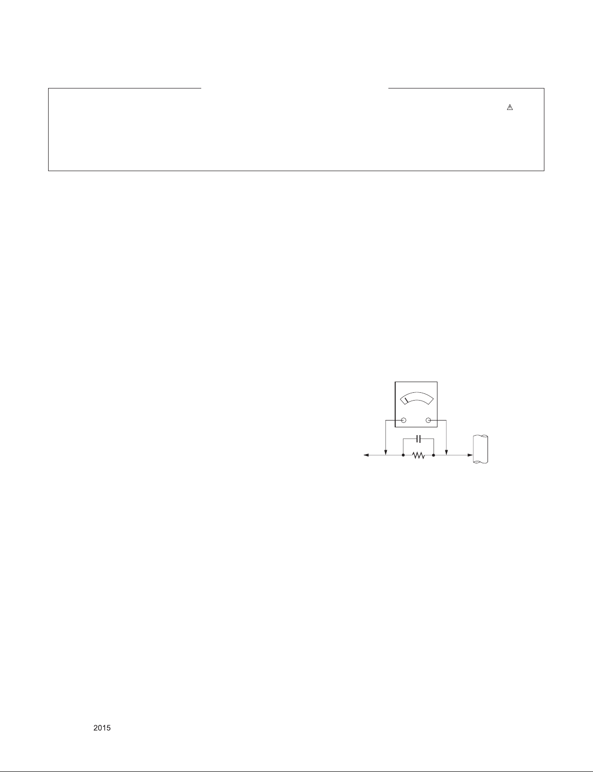
Leakage Current Hot Check (See below Figure)
Plug the AC cord directly into the AC outlet.
Do not use a line Isolation Transformer during this check.
Connect 1.5K/10watt resistor in parallel with a 0.15uF capacitor
between a known good earth ground (Water Pipe, Conduit, etc.)
and the exposed metallic parts.
Measure the AC voltage across the resistor using AC voltmeter
with 1000 ohms/volt or more sensitivity.
Reverse plug the AC cord into the AC outlet and repeat AC voltage
measurements for each exposed metallic part. Any voltage
measured must not exceed 0.75 volt RMS which is corresponds to
0.5mA.
In case any measurement is out of the limits specified, there is
possibility of shock hazard and the set must be checked and
repaired before it is returned to the customer.
Leakage Current Hot Check circuit
Good Earth Ground
such as WATER PIPE,
To Instrument's
exposed
METALLIC PARTS
When 25A is impressed between Earth and 2nd Ground
for 1 second, Resistance must be less than 0.1
*Base on Adjustment standard
0.15µF
1.5 Kohm/10W
CONDUIT etc.
Copyright © LG Electronics. Inc. All right reserved.
Only for training and service purposes
- 3 -
LGE Internal Use Only
Page 4

SERVICING PRECAUTIONS
CAUTION: Before servicing receivers covered by this service
manual and its supplements and addenda, read and follow the
SAFETY PRECAUTIONS on page 3 of this publication.
NOTE: If unforeseen circumstances create conflict between the
following servicing precautions and any of the safety precautions on
page 3 of this publication, always follow the safety precautions.
Remember: Safety First.
General Servicing Precautions
1. Always unplug the receiver AC power cord from the AC power
source before;
a. Removing or reinstalling any component, circuit board
module or any other receiver assembly.
b. Disconnecting or reconnecting any receiver electrical plug or
other electrical connection.
c. Connecting a test substitute in parallel with an electrolytic
capacitor in the receiver.
CAUTION: A wrong part substitution or incorrect polarity
installation of electrolytic capacitors may result in an
explosion hazard.
2. Test high voltage only by measuring it with an appropriate high
voltage meter or other voltage measuring device (DVM,
FETVOM, etc) equipped with a suitable high voltage probe.
Do not test high voltage by "drawing an arc".
3. Do not spray chemicals on or near this receiver or any of its
assemblies.
4. Unless specified otherwise in this service manual, clean
electrical contacts only by applying the following mixture to the
contacts with a pipe cleaner, cotton-tipped stick or comparable
non-abrasive applicator; 10% (by volume) Acetone and 90% (by
volume) isopropyl alcohol (90%-99% strength)
CAUTION: This is a flammable mixture.
Unless specified otherwise in this service manual, lubrication of
contacts in not required.
5. Do not defeat any plug/socket B+ voltage interlocks with which
receivers covered by this service manual might be equipped.
6. Do not apply AC power to this instrument and/or any of its
electrical assemblies unless all solid-state device heat sinks are
correctly installed.
7. Always connect the test receiver ground lead to the receiver
chassis ground before connecting the test receiver positive
lead.
Always remove the test receiver ground lead last.
8. Use with this receiver only the test fixtures specified in this
service manual.
CAUTION: Do not connect the test fixture ground strap to any
heat sink in this receiver.
Electrostatically Sensitive (ES) Devices
Some semiconductor (solid-state) devices can be damaged easily
by static electricity. Such components commonly are called
Electrostatically Sensitive (ES) Devices. Examples of typical ES
devices are integrated circuits and some field-effect transistors and
semiconductor "chip" components. The following techniques
should be used to help reduce the incidence of component
damage caused by static by static electricity.
1. Immediately before handling any semiconductor component or
semiconductor-equipped assembly, drain off any electrostatic
charge on your body by touching a known earth ground.
Alternatively, obtain and wear a commercially available
discharging wrist strap device, which should be removed to
prevent potential shock reasons prior to applying power to the
unit under test.
2. After removing an electrical assembly equipped with ES
devices, place the assembly on a conductive surface such as
aluminum foil, to prevent electrostatic charge buildup or
exposure of the assembly.
3. Use only a grounded-tip soldering iron to solder or unsolder ES
devices.
4. Use only an anti-static type solder removal device. Some solder
removal devices not classified as "anti-static" can generate
electrical charges sufficient to damage ES devices.
5. Do not use freon-propelled chemicals. These can generate
electrical charges sufficient to damage ES devices.
6. Do not remove a replacement ES device from its protective
package until immediately before you are ready to install it.
(Most replacement ES devices are packaged with leads
electrically shorted together by conductive foam, aluminum foil
or comparable conductive material).
7. Immediately before removing the protective material from the
leads of a replacement ES device, touch the protective material
to the chassis or circuit assembly into which the device will be
installed.
CAUTION: Be sure no power is applied to the chassis or circuit,
and observe all other safety precautions.
8. Minimize bodily motions when handling unpackaged
replacement ES devices. (Otherwise harmless motion such as
the brushing together of your clothes fabric or the lifting of your
foot from a carpeted floor can generate static electricity
sufficient to damage an ES device.)
General Soldering Guidelines
1. Use a grounded-tip, low-wattage soldering iron and appropriate
tip size and shape that will maintain tip temperature within the
range or 500 ˚F to 600 ˚F.
2. Use an appropriate gauge of RMA resin-core solder composed
of 60 parts tin/40 parts lead.
3. Keep the soldering iron tip clean and well tinned.
4. Thoroughly clean the surfaces to be soldered. Use a mall wirebristle (0.5 inch, or 1.25cm) brush with a metal handle.
Do not use freon-propelled spray-on cleaners.
5. Use the following unsoldering technique
a. Allow the soldering iron tip to reach normal temperature.
(500 ˚F to 600 ˚F)
b. Heat the component lead until the solder melts.
c. Quickly draw the melted solder with an anti-static, suction-
type solder removal device or with solder braid.
CAUTION: Work quickly to avoid overheating the circuit
board printed foil.
6. Use the following soldering technique.
a. Allow the soldering iron tip to reach a normal temperature
(500 ˚F to 600 ˚F)
b. First, hold the soldering iron tip and solder the strand against
the component lead until the solder melts.
c. Quickly move the soldering iron tip to the junction of the
component lead and the printed circuit foil, and hold it there
only until the solder flows onto and around both the
component lead and the foil.
CAUTION: Work quickly to avoid overheating the circuit
board printed foil.
d. Closely inspect the solder area and remove any excess or
splashed solder with a small wire-bristle brush.
Copyright © LG Electronics. Inc. All right reserved.
Only for training and service purposes
- 4 -
LGE Internal Use Only
Page 5

IC Remove/Replacement
Some chassis circuit boards have slotted holes (oblong) through
which the IC leads are inserted and then bent flat against the
circuit foil. When holes are the slotted type, the following technique
should be used to remove and replace the IC. When working with
boards using the familiar round hole, use the standard technique
as outlined in paragraphs 5 and 6 above.
Removal
1. Desolder and straighten each IC lead in one operation by gently
prying up on the lead with the soldering iron tip as the solder
melts.
2. Draw away the melted solder with an anti-static suction-type
solder removal device (or with solder braid) before removing the
IC.
Replacement
1. Carefully insert the replacement IC in the circuit board.
2. Carefully bend each IC lead against the circuit foil pad and
solder it.
3. Clean the soldered areas with a small wire-bristle brush.
(It is not necessary to reapply acrylic coating to the areas).
"Small-Signal" Discrete Transistor
Removal/Replacement
1. Remove the defective transistor by clipping its leads as close as
possible to the component body.
2. Bend into a "U" shape the end of each of three leads remaining
on the circuit board.
3. Bend into a "U" shape the replacement transistor leads.
4. Connect the replacement transistor leads to the corresponding
leads extending from the circuit board and crimp the "U" with
long nose pliers to insure metal to metal contact then solder
each connection.
CAUTION: Maintain original spacing between the replaced
component and adjacent components and the circuit board to
prevent excessive component temperatures.
Circuit Board Foil Repair
Excessive heat applied to the copper foil of any printed circuit
board will weaken the adhesive that bonds the foil to the circuit
board causing the foil to separate from or "lift-off" the board. The
following guidelines and procedures should be followed whenever
this condition is encountered.
At IC Connections
To repair a defective copper pattern at IC connections use the
following procedure to install a jumper wire on the copper pattern
side of the circuit board. (Use this technique only on IC
connections).
1. Carefully remove the damaged copper pattern with a sharp
knife. (Remove only as much copper as absolutely necessary).
2. carefully scratch away the solder resist and acrylic coating (if
used) from the end of the remaining copper pattern.
3. Bend a small "U" in one end of a small gauge jumper wire and
carefully crimp it around the IC pin. Solder the IC connection.
4. Route the jumper wire along the path of the out-away copper
pattern and let it overlap the previously scraped end of the good
copper pattern. Solder the overlapped area and clip off any
excess jumper wire.
At Other Connections
Use the following technique to repair the defective copper pattern
at connections other than IC Pins. This technique involves the
installation of a jumper wire on the component side of the circuit
board.
Power Output, Transistor Device
Removal/Replacement
1. Heat and remove all solder from around the transistor leads.
2. Remove the heat sink mounting screw (if so equipped).
3. Carefully remove the transistor from the heat sink of the circuit
board.
4. Insert new transistor in the circuit board.
5. Solder each transistor lead, and clip off excess lead.
6. Replace heat sink.
Diode Removal/Replacement
1. Remove defective diode by clipping its leads as close as
possible to diode body.
2. Bend the two remaining leads perpendicular y to the circuit
board.
3. Observing diode polarity, wrap each lead of the new diode
around the corresponding lead on the circuit board.
4. Securely crimp each connection and solder it.
5. Inspect (on the circuit board copper side) the solder joints of
the two "original" leads. If they are not shiny, reheat them and if
necessary, apply additional solder.
Fuse and Conventional Resistor
Removal/Replacement
1. Clip each fuse or resistor lead at top of the circuit board hollow
stake.
2. Securely crimp the leads of replacement component around
notch at stake top.
3. Solder the connections.
1. Remove the defective copper pattern with a sharp knife.
Remove at least 1/4 inch of copper, to ensure that a hazardous
condition will not exist if the jumper wire opens.
2. Trace along the copper pattern from both sides of the pattern
break and locate the nearest component that is directly
connected to the affected copper pattern.
3. Connect insulated 20-gauge jumper wire from the lead of the
nearest component on one side of the pattern break to the lead
of the nearest component on the other side.
Carefully crimp and solder the connections.
CAUTION: Be sure the insulated jumper wire is dressed so the
it does not touch components or sharp edges.
Copyright © LG Electronics. Inc. All right reserved.
Only for training and service purposes
- 5 -
LGE Internal Use Only
Page 6
SPECIFICATION
NOTE : Specications and others are subject to change without notice for improvement.
1. Application Range
This spec sheet is applied all of the TV used LW45A chassis.
2. Specication
Each part is tested as below without special appointment
1) Temperature : 25 ˚C ± 5 ˚C (77 ˚F ± 9 ˚F),
CST : 40 ˚C ± 5 ˚C
2) Relative Humidity : 65 % ± 10 %
3) Power Voltage : Standard input voltage
(100 V - 240 V ~, 50 / 60 Hz)
· Standard Voltage of each products is marked by models
4) Specication and performance of each parts are followed
each drawing and specication by part number in accord-
ance with BOM.
5) The receiver must be operated for about 5 minutes prior to
the adjustment.
3.Test method
1) Performance : LGE TV test method followed
2) Demanded other specication
- Safety : CE,IEC specication
- EMC : CE,IEC specication
4. General specication
4.1. Operating/Storage environment
1 Operating Environment
2 Storage Environment
4.2. RGB-PC
No. Item Specication Remarks
1 Supported Sync. Type Separate Sync.(RGB)
2 Operating Frequency Analog
3 Resolution Analog
Temp : 10 °C ~ 35 °C
Humidity : 20 % ~ 80 %
Temp : -10 °C ~ 60 °C non condensing
Humidity : 5 % ~ 90 % non condensing
Horizontal 30 ~ 69 kHz
Vertical 56 ~ 61 Hz
Max 1920×1080 @ 60 Hz
Recommend 1920×1080 @ 60 Hz
Max 1366×768 @ 60 Hz
Recommend 1366×768 @ 60 Hz
Max. 1600×900 @ 60Hz 1600×900 @ 60Hz
Recommend 1600×900 @ 60Hz 1600×900 @ 60Hz
22MT47A, 24MT47A,28MT47A,29MT47A
22MT48A,22MT48N,24MT48N
21MT47A,22MT47A, 22MT48A,22MT48N
24MT47A,24MT48N,28MT47A,29MT47A
Copyright © LG Electronics. Inc. All right reserved.
Only for training and service purposes
- 6 -
LGE Internal Use Only
Page 7
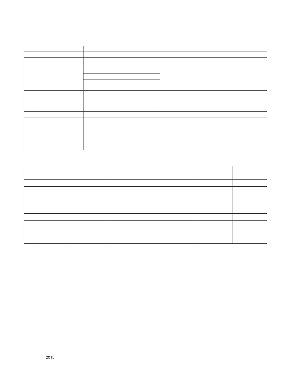
4.3. TV
No. Item Specication Remarks
1 Market NON EU
2 Broadcasting system
3 Available Channel
4 Receiving system Upper Heterodyne
5 Video Input PAL, SECAM, NTSC
6 RGB Input RGB-PC(Analog (D-SUB 15Pin) Rear (1EA)
7 USB Input MP3, JPEG, Movie Rear (1EA) or Side(1EA)
8 AV Audio Output RF/AV/HDMI Audio Output Rear (1EA)
9 HDMI Input HDMI-DTV Rear (1EA)
10 Audio Input (1EA) AV&RGB-PC
PAL/SECAM B/G/D/K,
PAL I, NTSC-M
PAL(BG,I) NTSC(M) China(DK)
S1~S47 1~71 S1~S47
Except for the 47M.01~C69 2~78 C1~C69
Rear (1EA) – MT47A/MT48A
Rear(2EA) – MT48N
Except for the 47M.
AV
RGB-PC
L/R Input(1EA) – MT47A/MT48A
L/R Input(2EA) – MT48N(AV1/AV2)
L/R Input(1EA) – MT47A/MT48A
L/R Input(1EA) – MT48N(Only AV1)
5. RGB-PC Input ( PC )
No. Resolution H-freq(kHz) V-freq.(Hz) Pixel clock(MHz) Proposed Remark
1 640*480 31.469 59.94 25.175
2 800*600 37.879 60.317 40.0
3 1024*768 48.363 60.0 65.0
4 1152*864 54.34 60.05 80
5 1280*1024 63.981 60.02 108.0
6 1600*900 55.54 60 97.75
7 1680*1050 64.674 59.883 119.0
8 1680*1050 65.290 59.954 146.25
Max Resolution
9 1920*1080 67.5 60 148.5
* Monitor Range Limits
Min Vertical Freq - 56 Hz/ Max Vertical Freq - 61 Hz
Min Horiz. Freq - 30 kHz/ Max Horiz. Freq - 69 kHz
Pixel Clock - 150 MHz
Recommend
Resolution
Copyright © LG Electronics. Inc. All right reserved.
Only for training and service purposes
- 7 -
LGE Internal Use Only
Page 8

6. HDMI Input (DTV)
No Resolution H-freq(kHz) V-freq.(kHz) Pixel clock(MHz) Proposed Remarks
1 720*480 15.73 59.94 13.500 SDTV, DVD 480I(525I)
Spec. out but display.2 720*480 15.75 60.00 13.514 SDTV, DVD 480I(525I)
3 720*576 15.625 50.00 13.500 SDTV, DVD 576I(625I) 50Hz
4 720*480 31.469 59.94 27 SDTV 480P
5 720*480 31.5 60.00 27.027 SDTV 480P
6 720*576 31.25 50.00 27 SDTV 576P
7 1280*720 44.96 59.94 74.176 HDTV 720P
8 1280*720 45 60.00 74.25 HDTV 720P
9 1280*720 37.5 50.00 74.25 HDTV 720P
10 1920*1080 28.125 50.00 74.25 HDTV 1080I
11 1920*1080 33.72 59.94 74.176 HDTV 1080I
12 1920*1080 33.75 60.00 74.25 HDTV 1080I
13 1920*1080 56.25 50.00 148.5 HDTV 1080P
14 1920*1080 67.432 59.94 148.350 HDTV 1080P
15 1920*1080 67.5 60.00 148.5 HDTV 1080P
16 1920*1080 27 24.00 74.25 HDTV 1080P
17 1920*1080 33.75 30.00 74.25 HDTV 1080P
18 1920*1080 26.97 23.97 74.25 HDTV 1080P
Max Resolution
19 1920*1080 33.716 29.976 74.25 HDTV 1080P
Recommend Resolution
Copyright © LG Electronics. Inc. All right reserved.
Only for training and service purposes
- 8 -
LGE Internal Use Only
Page 9

ADJUSTMENT INSTRUCTION
1. Application Range
This spec. sheet applies to LW45A Chassis applied TV all
models manufactured in TV factory
2. Specication
1) Because this is not a hot chassis, it is not necessary to
use an isolation transformer. However, the use of isolation
transformer will help protect test instrument.
2) Adjustment must be done in the correct order.
3) The adjustment must be performed in the circumstance of
25 °C ± 5 °C of temperature and 65 % ± 10 % of relative
humidity if there is no specic designation.
4) The input voltage of the receiver must keep AC 100-240
V~, 50/60 Hz.
5) The receiver must be operated for about 5 minutes prior to
the adjustment when module is in the circumstance of over
15. In case of keeping module is in the circumstance of 0
°C, it should be placed in the circumstance of above 15
°C for 2 hours. In case of keeping module is in the circumstance of below -20 °C, it should be placed in the circumstance of above 15 °C for 3 hours.
[Caution]
When still image is displayed for a period of 20 minutes or
longer (Especially where W/B scale is strong. Digital pattern
13ch and/or Cross hatch pattern 09ch), there can some afterimage in the black level area.
3. ADC calibration
3.1. PC input ADC
- An ADC calibration is automatically adjusted from DFT-Jig
- If it needs to adjust manually, refer to appendix.
NO Item CMD 1CMD 2Data 0
3.2.4. EDID DATA
- 21MT47A,22MT47A, 22MT48A ,22MT48N(RGB-PC)
** RGB-PC : 128Bytes
0 1 2 3 4 5 6 7 8 9 A B C D E F
0 00 FF FF FF FF FF FF 00 1E 6D C4 59 01 01 01 01
10 01 17 01 03 68 30 1B 78 EA EB F5 A6 56 51 9C 26
20 10 50 54 A1 08 00 B3 00 81 80 81 C0 71 40 A9 C0
30 95 00 90 40 81 00 02 3A 80 18 71 38 2D 40 58 2C
40 45 00
50 45 0F 00 0A 20 20 20 20 20 20 00 00 00 FC 00 32
60 44 20 46 48 44 20 4C 47 20 54 56 0A 00 00 00 FF
70 00 0A 20 20 20 20 20 20 20 20 20 20 20 20 00 FC
- 21MT47A,22MT47A, 22MT48A,22MT48N (HDMI)
** HDMI : 256Bytes
0 00 FF FF FF FF FF FF 00 1E 6D C6 59 01 01 01 01
10 01 17 01 03 80 30 1B 78 EA EB F5 A6 56 51 9C 26
20 10 50 54 21 08 00 B3 00 81 80 71 40 81 C0 81 00
30 95 00 90 40 A9 C0 02 3A 80 18 71 38 2D 40 58 2C
40 45 00 DC 0C 11 00 00 1E 21 39 90 30 62 1A 27 40
50 68 B0 36 00 DC 0C 11 00 00 1C 00 00 00 FD 00 38
60 3D 1E 45 0F 00 0A 20 20 20 20 20 20 00 00 00 FC
70 00 32 44 20 46 48 44 20 4C 47 20 54 56 0A 01 8A
80 02 03 21 F1 4F 04 05 03 02 20 22 90 11 12 13 14
90 1F 07 16 01 26 11 07 50 09 7F 07 65 03 0C 00 10
A0 00 02 3A 80 18 71 38 2D 40 58 2C 45 00 DC 0C 11
B0 00 00 1A 01 1D 80 18 71 1C 16 20 58 2C 25 00 DC
C0 0C 11 00 00 9E 01 1D 00 72 51 D0 1E 20 6E 28 55
D0 00 DC 0C 11 00 00 1E 01 1D 80 D0 72 1C 16 20 10
E0 2C 25 80 DC 0C 11 00 00 9E 02 3A 80 D0 72 38 2D
F0 40 10 2C 45 20 DC 0C 11 00 00 1E 00 00 00 00 1D
DC
0C 11 00 00 1E 00 00 00 FD 00 38 3D 1E
0 1 2 3 4 5 6 7 8 9 A B C D E F
Enter
Adjust MODE
ADC
adjust
Adjust
‘Mode In’
ADC
adjust
A A 0 0 When transfer the
A D 1 0 Automatically adjustment
‘Mode In’,
Carry the command.
Adjust Sequence
▪aa 00 00 [Enter Adjust Mode]
▪xb 00 60 [RGB Input (1024*768)]
▪ad 00 10 [Adjust 1024*768 RGB]
▪aa 00 90 End Adjust mode
3.2. EDID Download
3.2.1. Overview
- It is a VESA regulation. A PC or a MNT will display an
optimal resolution through information sharing without any
necessity of user input. It is a realization of “Plug and Play”.
3.2.2. Equipment
- Since EDID data is embedded, EDID download JIG, HDMI
cable and D-sub cable are not need.
3.2.3. Download method
- The EDID data is automatically saved.
Copyright © LG Electronics. Inc. All right reserved.
Only for training and service purposes
- 9 -
LGE Internal Use Only
Page 10

4. Final Assembly Adjustment
4.1. White Balance Adjustment
4.1.1. Overview
▪ W/B adj. Objective & How-it-works
(1) Objective: To reduce each Panel's W/B deviation
(2) How-it-works : When R/G/B gain in the OSD is at 192, it
means the panel is at its Full Dynamic Range. In order to
prevent saturation of Full Dynamic range and data, one of
R/G/B is xed at 192, and the other two is lowered to nd
the desired value.
(3) Adjustment condition : normal temperature
1) Surrounding Temperature : 25 °C ± 5 °C
2) Warm-up time: About 5 Min
3) Surrounding Humidity : 20 % ~ 80 %
4) Before White balance adjustment, Keep power on
status, don’t power off
* Adj. condition and cautionary items
(1) Lighting condition in surrounding area surrounding lighting
should be lower 10 lux. Try to isolate adj. area into dark
surrounding.
(2) Probe location: Color Analyzer (CA-210) probe should
be within 10cm and perpendicular of the module surface
(80°~ 100°)
(3) Aging time
1) After Aging Start, Keep the Power ON status during
5 Minutes.
2) In case of LCD, Back-light on should be checked
using no signal or Full-white pattern.
4.1.2. Equipment
(1) Color Analyzer: CA-210 (NCG: CH 9 / WCG: CH12 / LED:
CH14)
(2) Adj. Computer (During auto adj., RS-232C protocol is
needed)
(3) Adjust Remocon
(4) Video Signal Generator MSPG-925F 720p/204-
Gray(Model: 217, Pattern: 49)
* Color Analyzer Matrix should be calibrated using CS-1000
4.1.4. Adjustment Command (Protocol)
(1) RS-232C Command used during auto-adj.
RS-232C COMMAND
CMD ID DATA
wb 00 00 Begin White Balance adjustment
wb 00 ff
End White Balance adjustment
(internal pattern disappears )
(2) Adjustment Map
Command
(lower caseASCII)
CMD1 CMD2 MIN MAX
Cool
Medium
Warm
Adj. item
R Gain j g 00 C0
G Gain j h 00 C0
B Gain j i 00 C0
R Cut
G Cut
B Cut
R Gain j a 00 C0
G Gain j b 00 C0
B Gain j c 00 C0
R Cut
G Cut
B Cut
R Gain j d 00 C0
G Gain j e 00 C0
B Gain j f 00 C0
R Cut
G Cut
Explantion
Data Range
(Hex.)
Default
(Decimal)
4.1.3. Equipment connection
Color Analyzer
Probe
DFTJIG
RRGB Cable S-232C
Signal Source
* If TV internal pattern is used, not needed
Copyright © LG Electronics. Inc. All right reserved.
Only for training and service purposes
Computer
Pattern Generator
RS-232C
RS-232C
- 10 -
LGE Internal Use Only
Page 11

4.1.5. Adj. method
*Auto WB calibration
1) Set TV in ADJ mode using P-ONLY key (or POWER ON
key)
2) Place optical probe on the center of the display
- It need to check probe condition of zero calibration
before adjustment.
3) Connect RS-232C Cable
4) Select mode in ADJ Program and begin a adjustment.
5) When WB adjustment is completed with OK message,
check adjustment status of pre-set mode (Cool, Medium,
Warm)
6) Remove probe and RS-232C cable.
▪ W/B Adj. must begin as start command “wb 00 00” , and n-
ish as end command “wb 00 ff”, and Adj. offset if need.
* LED White balance table
If Model is Polaris Model, G-gain x is applied.
(1) Cool Mode
1) Purpose : Especially G-gain x adjust leads to the lu-
minance enhancement. Adjust the color temperature
to reduce the deviation of the module color temperature.
2) Principle : To adjust the white balance without the
saturation, Adjust the G gain more than 172 ( If R
gain or G gain is more than 255 , G gain can adjust
less than 172 ) and change the others ( R/B Gain ).
3) Adjustment mode : mode – Cool
(2) Medium / Warm Mode
1) Purpose : Adjust the color temperature to reduce the
deviation of the module color temperature.
2) Principle : To adjust the white balance without the
saturation, Fix the one of R/G/B gain to 192 (default
data) and decrease the others.
3)Adjustment mode : Two modes – Medium / Warm
4.1.6 Reference
(White Balance Adj. coordinate and color temperature)
1) Luminance: 204 Gray, 80IRE
2) Standard color coordinate and temperature using CS-1000
(over 26 inch)
4.1.7. Reference
(White Balance Adj. coordinate and color temperature)
* The spec of color temperature and coordinate.
Color
Temperature
Luminance
(cd/m²)
*Note : x,y coordinates are drifted about 0.007 after 30 mins
heat-run. So checking color coordinate within 5-min at total
assembly line, consider x,y coordinates might be up to 0.007
than x,y target of each color temperature.
Cool 9,300K °K x= 0.291 (±0.04)
Medium 8,000K °K x= 0.300 (±0.04)
Warm 6,500K °K x= 0.318 (±0.04)
Cool Min : 80 Typ : 110 <Test Signal>
Medium Min : 80 Typ : 110
Warm Min : 70 Typ : 110
y= 0.294 (±0.04)
y= 0.310 (±0.04)
y= 0.334 (±0.04)
<Test Signal>
- Inner pattern
for W/B adjust
- External white
pattern
(80IRE, 204gray)
Inner pattern
(204gray,80IRE)
5. Tool Option selection
▪ Method : Press "ADJ" key on the Adjustment remote control,
then select Tool option.
6. Ship-out mode check(In-stop)
▪ After nal inspection, press "IN-STOP" key of the Adjustment
remote control and check that the unit goes to Stand-by
mode.
7. GND and Hi-pot
7.1. GND & HI-POT auto-check preparation
1) Check the POWER CABLE and SIGNAL CABE insertion
condition
7.2. GND & HI-POT auto-check
1) Pallet moves in the station. (POWER CORD / AV CORD is
tightly inserted)
2) Connect the AV JACK Tester.
3) Controller (GWS103-4) on.
4) GND Test (Auto)
- If Test is failed, Buzzer operates.
- If Test is passed, execute next process (Hi-pot test).
(Remove A/V CORD from A/V JACK BOX)
5) HI-POT test (Auto)
- If Test is failed, Buzzer operates.
- If Test is passed, GOOD Lamp on and move to next
process automatically.
7.3. Checkpoint
1) Test voltage
- GND: 1.5KV/min at 100mA
- SIGNAL: 3KV/min at 100mA
2) TEST time: 1 second
3) TEST POINT
- GND Test = POWER CORD GND and SIGNAL CA-
BLE GND.
- Hi-pot Test = POWER CORD GND and LIVE & NEU-
TRAL.
4) LEAKAGE CURRENT: At 0.5mArms
8. Audio
Measurement condition:
1) RF input: Mono, 1 KHz sine wave signal, 100 % Modulation
2) CVBS, Component: 1 KHz sine wave signal 0.5 Vrms
3) RGB PC: 1 KHz sine wave signal 0.7 Vrms
No. Item Min Typ Max Unit Remark
Audio practical
max Output, L/R
1
(Distortion=10%
max Output)
4.5 5.0 6.0WVrms
(1) Measurement condition
- EQ/AVL/Clear Voice: Off
(2) Speaker(8Ω Impedance)
Copyright © LG Electronics. Inc. All right reserved.
Only for training and service purposes
- 11 -
LGE Internal Use Only
Page 12
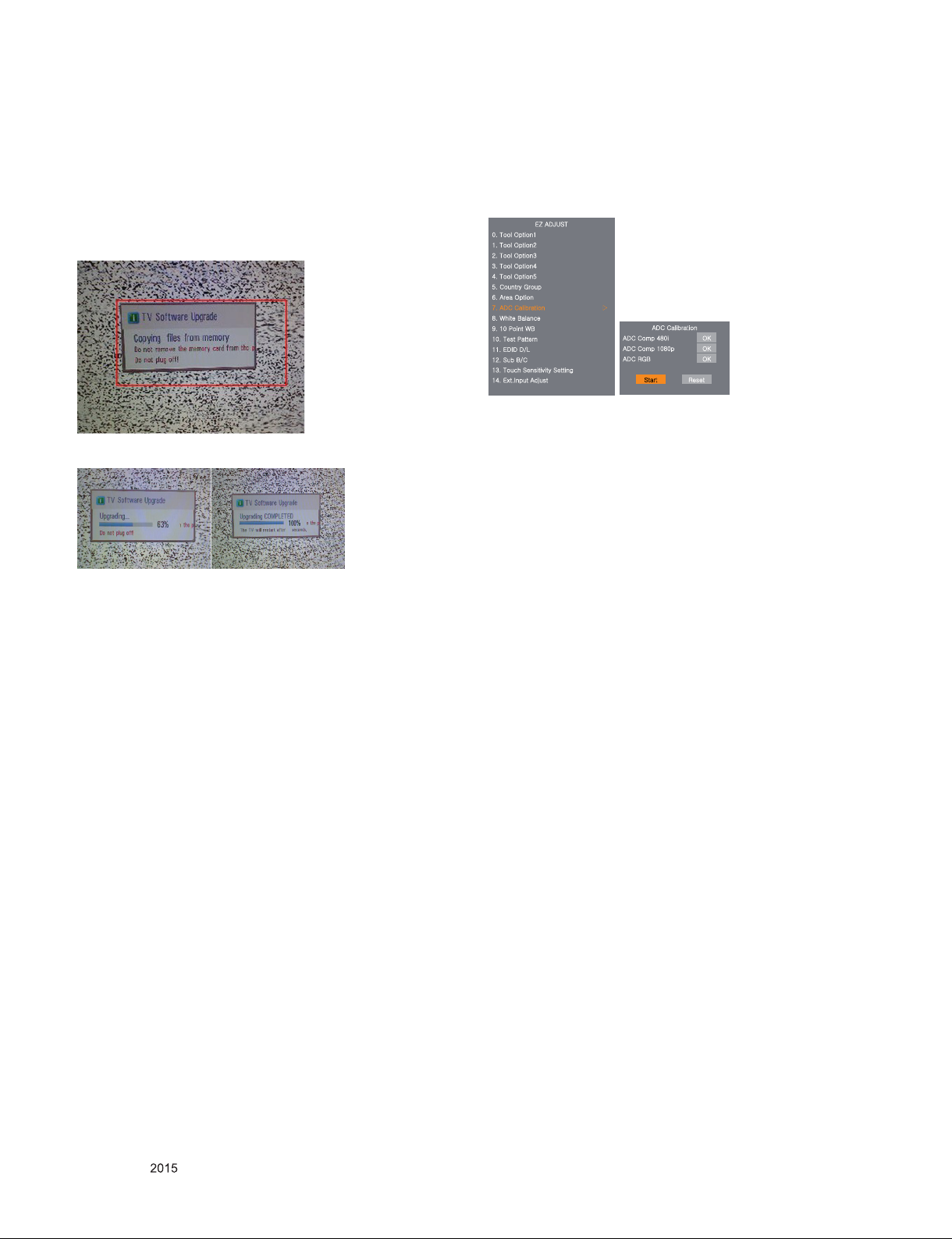
9. USB S/W Download(Service only)
1) Put the USB Stick to the USB socket.
2) Automatically detecting update le in USB Stick.
- If your downloaded program version in USB Stick is Low, it
didn't work. But your downloaded version is High, USB data
is automatically detecting.(Download Version High & Power
only mode, Set is automatically Download)
3) Show the message "Copying les from memory".
4) Updating is starting.
5) Updating Completed, The TV will restart automatically.
6) If your TV is turned on, check your updated version and
Tool option. (explain the Tool option, next stage)
* If downloading version is more high than your TV have, TV
can lost all channel data. In this case, you have to channel
recover. if all channel data is cleared, you didn’t have a DTV/
ATV test on production line.
* After downloading, have to adjust Tool Option again.
1) Push "IN-START" key in service remote control.
2) Select "Tool Option 1" and push "OK" key.
3) Punch in the number. (Each model has their number)
10. Optional adjustments
10.1. Manual ADC Calibration
■ Enter ‘EZ ADJUST’ mode by pressing ‘ADJ’ key.
■ Enter Internal ADC calibration mode by pressing ‘►’ or ‘OK’
key at ‘ADC Calibration’
lGhkq|z{G
WUG{GvXG G G
XUG{GvYG G G
YUG{GvZG G G
ZUG{Gv[G G G
[UG{Gv\G G G
\UGjGnG G G
]UGhGvG G G
^UGhkjGjG G ඖG
_UG~GiG G G
`UGXWGwG~iG G G
XWUG{GwG G G
XXUGlkpkGkVsG G G
XYUGzGiVjG
XZUG{GzGzG
X[UGlUpGhG
G
G G
→ Caution : Using ‘P-ONLY’ button of the Factory SVC remo-
con when turns TV on.
10.2. Manual White balance Adjustment
10.2.1. Adj. condition and cautionary items
(1) Lighting condition in surrounding area surrounding lighting
should be lower 10 lux. Try to isolate adj. area into dark
surrounding.
(2) Probe location: Color Analyzer (CA-210) probe should be
within 10cm and perpendicular of the module surface.(80°~
100°)
(3) Aging time
1) After Aging Start, Keep the Power ON status during 5
Minutes.
2) In case of LCD, Back-light on should be checked using no signal or Full-white pattern.
10.2.2. Equipment
(1) Color Analyzer: CA-210 (NCG: CH 9 / WCG: CH12 / LED:
CH14)
(2) Adj. Computer (During auto adj., RS-232C protocol is
needed)
(3) Adjust Remocon
(4) Video Signal Generator MSPG-925F 720p/216-Gray
(Model: 217, Pattern: 78)
hkjGjG
h
kjGjG[_WG vrG
hkjGjGXW_WG vrG
hkjGyniG vrG
G zG yG
G
G
Copyright © LG Electronics. Inc. All right reserved.
Only for training and service purposes
10.2.3. Adjustment
(1) Set TV in Adj. mode using POWER ON
(2) Zero Calibrate the probe of Color Analyzer, then place it on
the center of LCD module within 10cm of the surface.
(3) Press ADJ key → EZ adjust using adj. R/C → White Bal-
ance then press the cursor to the right (KEY►). When
KEY(►) is pressed 216 Gray internal pattern will be
displayed.
(4) One of R Gain / G Gain / B Gain should be xed at 192,
and the rest will be lowered to meet the desired value.
(5) Adj. is performed in COOL, MEDIUM, WARM 3 modes of
color temperature.
▪ If internal pattern is not available, use RF input. In EZ Adj.
menu 6.White Balance, you can select one of 2 Test-pattern:
ON, OFF. Default is inner(ON). By selecting OFF, you can
adjust using RF signal in 216 Gray pattern.
- 12 -
LGE Internal Use Only
Page 13
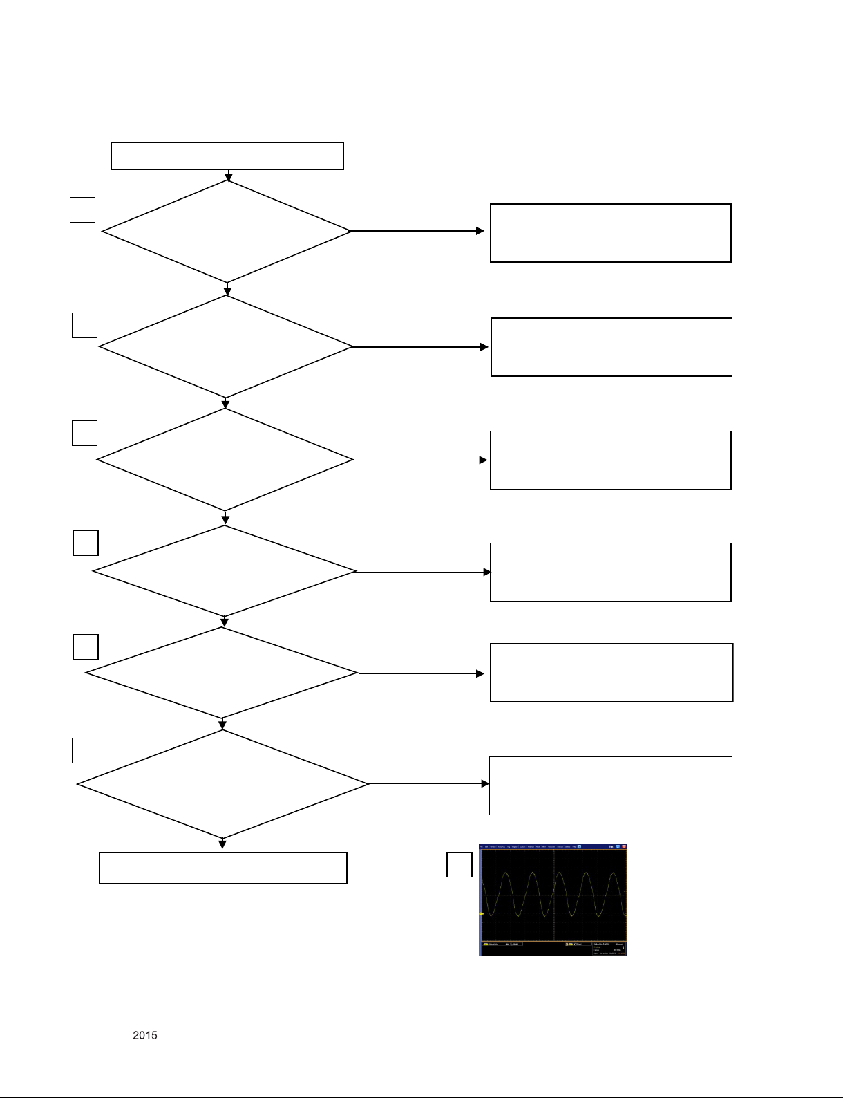
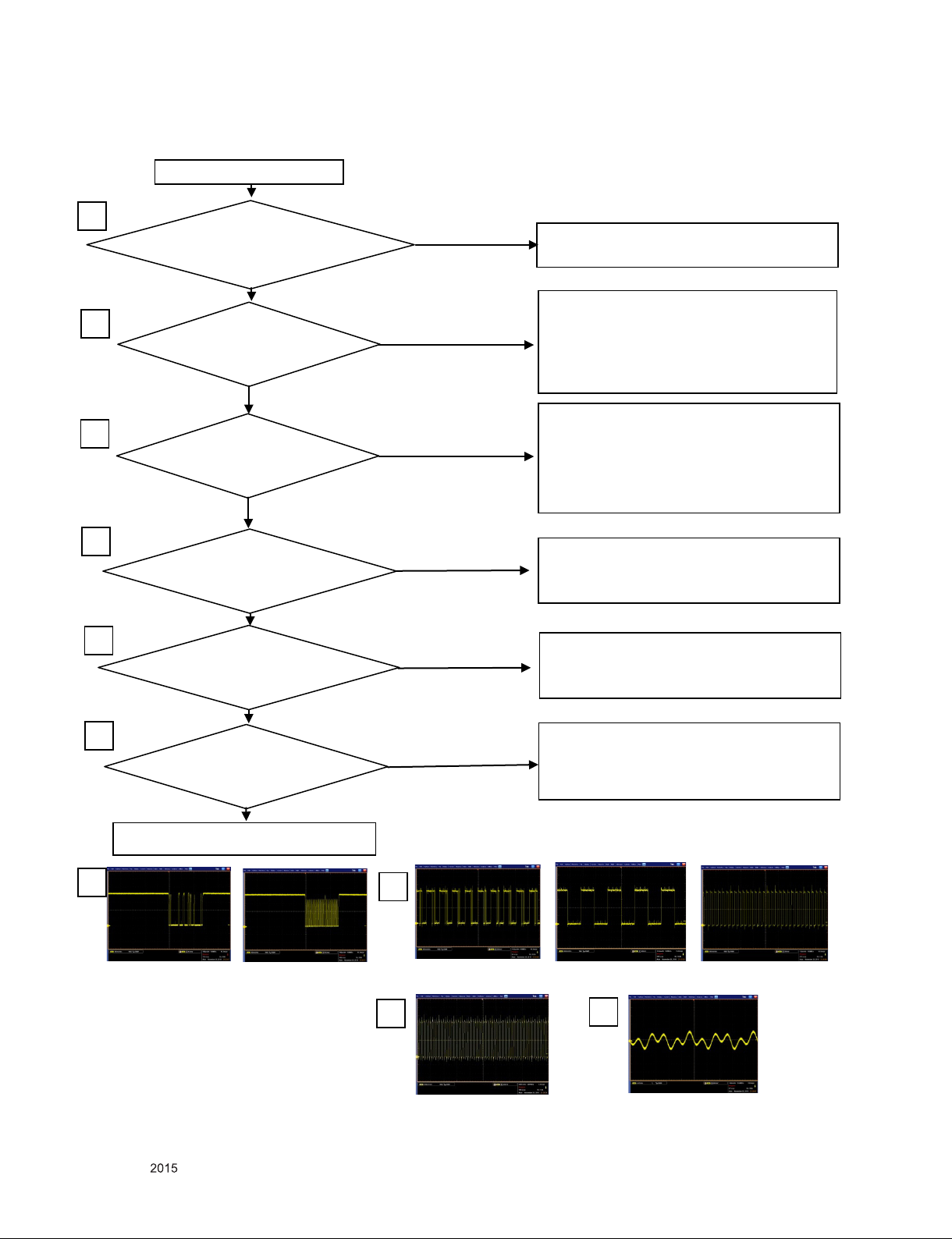
1. NO POWER-Main PCBA
Is Adapter
Output VOLTAGE 19.4V
thr ou gh of JK700?
NO POWER
Is 3.3V at C708?
Chec k wave form of X501
YES
NO
YES
NO
YES
check o pen or short at Line.
or change Adapter.
check the Lines of IC701,
If there is any pro blem at Line,
Change IC701
NO
Check Line short or o pen between
IC501 and X501,
Change IC501 or change X501
1
2
4
Is 1.8V at C745?
is 1.25V at C742?
3
YES
check the Lines of IC711,IC704
If there is any pro blem at Line,
Change IC704,IC706.
NO
Insert F/W
is 3.3V at 1pin of P 120?
when push power key,
Is 0v at 2pin of P120?
Change c ontrol
Or check Line short o r open o f P120
5
is ther e any wa ver at 11pin of P120,
when use remote controller?
6
NO
YES
chang e IR board
Or check Line short o r open o f P120
NO
4
X501
TROUBLE SHOOTING
Copyright © LG Electronics. Inc. All right reserved.
Only for training and service purposes
- 13 -
LGE Internal Use Only
Page 14
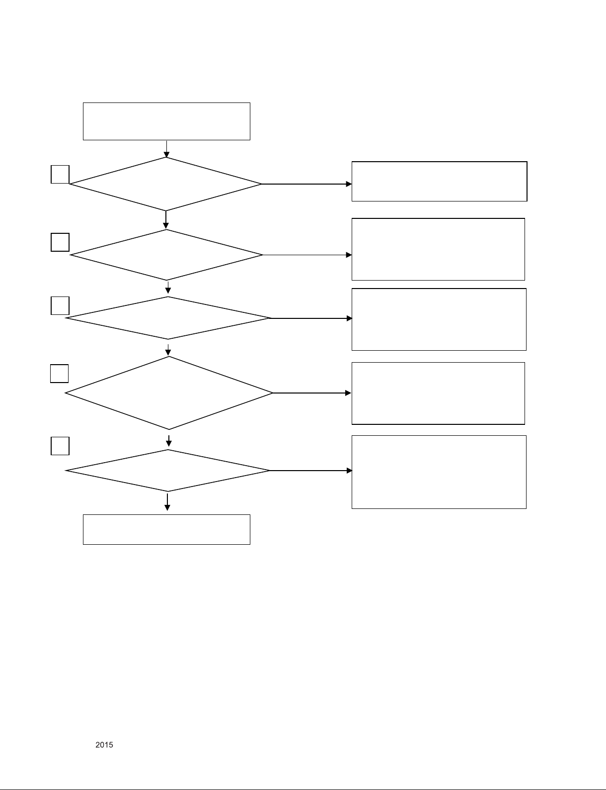
2. No raster (Power LED blue, black screen)
Is 19.4V a t JK700?
NO RASTER
(Screen is not d isplayed)
Insert the F/W back
or RE PLACE LCD MODULE
Is 1.25V at 4pin of IC704?
Is 1.8V at 2pin of IC711?
YES
NO
YES
Check Line short or o pen between
IC711/IC704 and IC501,
If there is any pro blem at Line,
Change IC711/IC704 or change IC501
NO
1
2
is 3V at 1pin of IC601?
YES
It is not over 3V at 1p in of IC601.
Change Q601.
Or check Line short o r open b etween
R603 and 95pin of IC501.
Change IC 501.
4
3
NO
check o pen or short at Line.
or change Adapter
is 5V at 1pin of P 101?
If is not under 1.5V at R722,
chang e Q721 or check o pen and s hort
of Line amo ng Q720 and Q721.
If is under 4.5V at L110,
Check open and short
Of line between L110 and P101.
NO
Put into LVDS cable completely?
LVDS cable have damage?
NO
If LVDS cable isn’t insulted enough,
Insult LVDS cab le until lock ing hook.
If LVDS cable have damage,
Change LVDS cable
5
YES
YES
Copyright © LG Electronics. Inc. All right reserved.
Only for training and service purposes
- 14 -
LGE Internal Use Only
Page 15
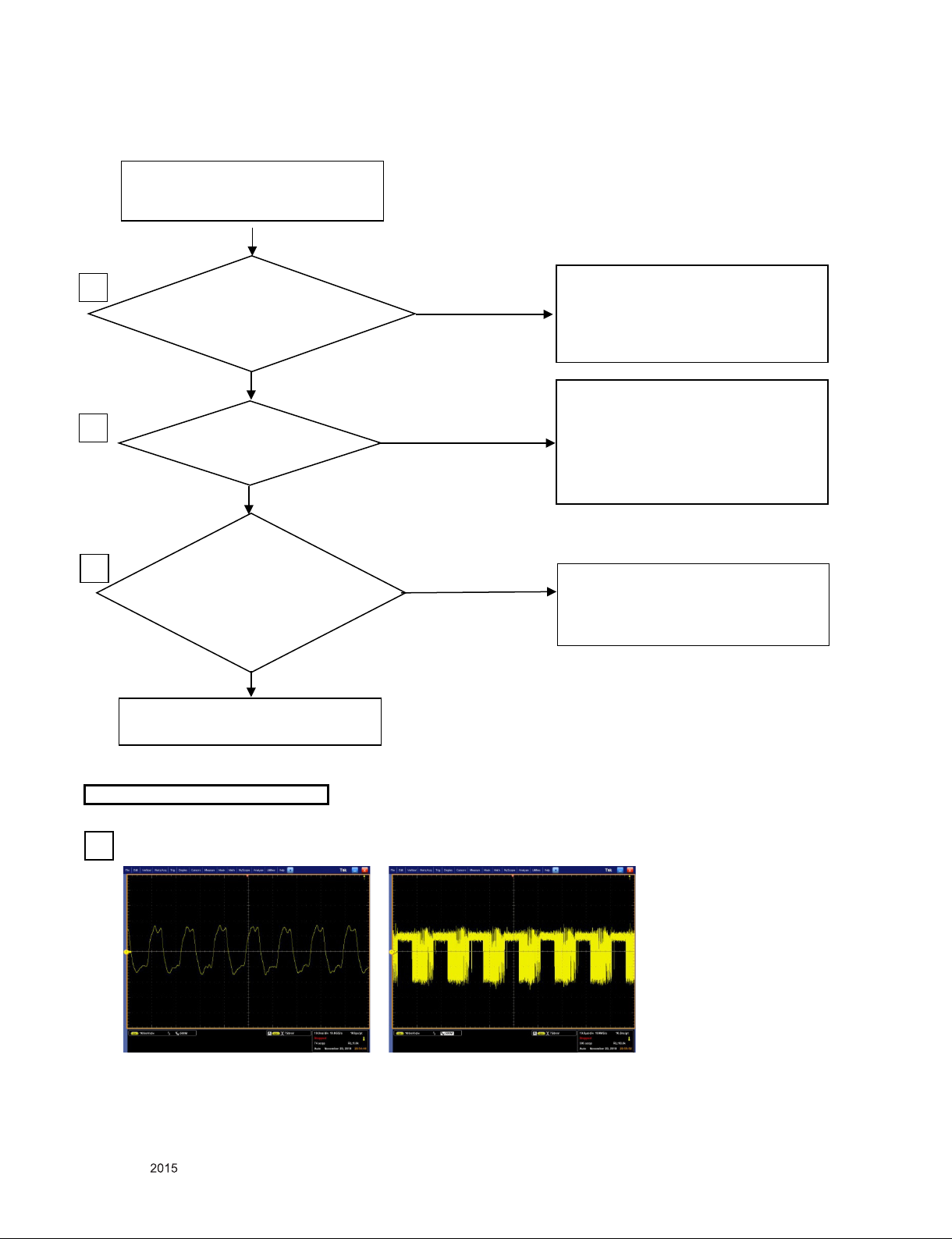
3. Abnormal/No screen (All input)-Main PCBA
Put into LVDS cable completely?
LVDS cable have damage?
Ab normal/No screen
(all input)
Check waveform at signal
lin e of P101 (Clock:9,10
Data: 6,7,12, 13,15,1 6,18,1 9)
YES
NO
YES
NO
YES
If LVDS cable isn’t insulted enough,
Insult LVDS cab le until lock ing hook.
If LVDS cable have damage,
Change LVDS cable
1
Change mod ule
WAVE FORMS
3
Is 12V a t 1pin of P 101?
If is not under 1.5V at R722,
chang e Q721 or check o pen and s hort
of Line amo ng Q720 and Q721.
If is under 11V at L110,
Check open and short
Of line between L110 and P101.
2
3
NO
Check open and short
Of line between Q720 and P101.
Or Check LVDS cable have damage.
Ano ther is change IC501.
6,7,12,13,15,1 6,18,1 9 Pin of 1201
(Data Line)
9,10Pin of P101
(Clock line)
Copyright © LG Electronics. Inc. All right reserved.
Only for training and service purposes
- 15 -
LGE Internal Use Only
Page 16
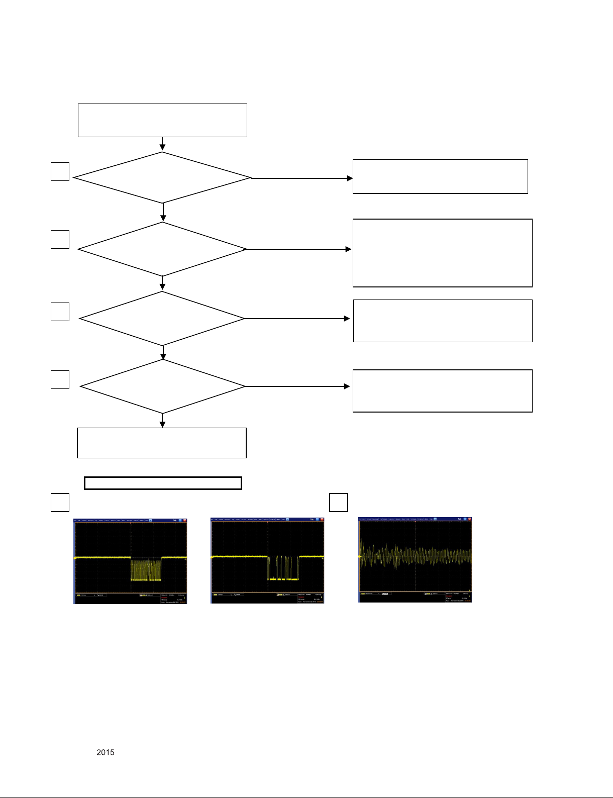
4. Abnormal screen (TV)-Main PCBA
Put into RF cable completely?
Ab normal screen (TV)
YES
NO
NO
insult RF cable tig ht and then
Cable nut screw tight.
1
Change Main PCBA
WAVE FORMS
Is 1.8V at 7pin of TU401?
2
Is I2C wavefor m
At 3,4pin of TU401?
3
4
Is IF wa ve form at 43
,44 pin of IC501?
NO
NO
3
3Pin of TU401 (SCL)
4Pin of TU401 (SDA)
4
43,44pin of IC501
If 1.7V is no t at plus pin of TU401, check
It is over 3V at 2pin of IC711,
if it is not, Check Line between TU401
and IC711 is op en or sho rt.
Ano ther is change IC711 or TU401
Check Line between TU401 and IC501
is op en or short, Another is change
IC501 or TU401
Check Line between TU401 and IC501
is op en or short, Another is change
IC501 or TU401
Copyright © LG Electronics. Inc. All right reserved.
Only for training and service purposes
- 16 -
LGE Internal Use Only
Page 17
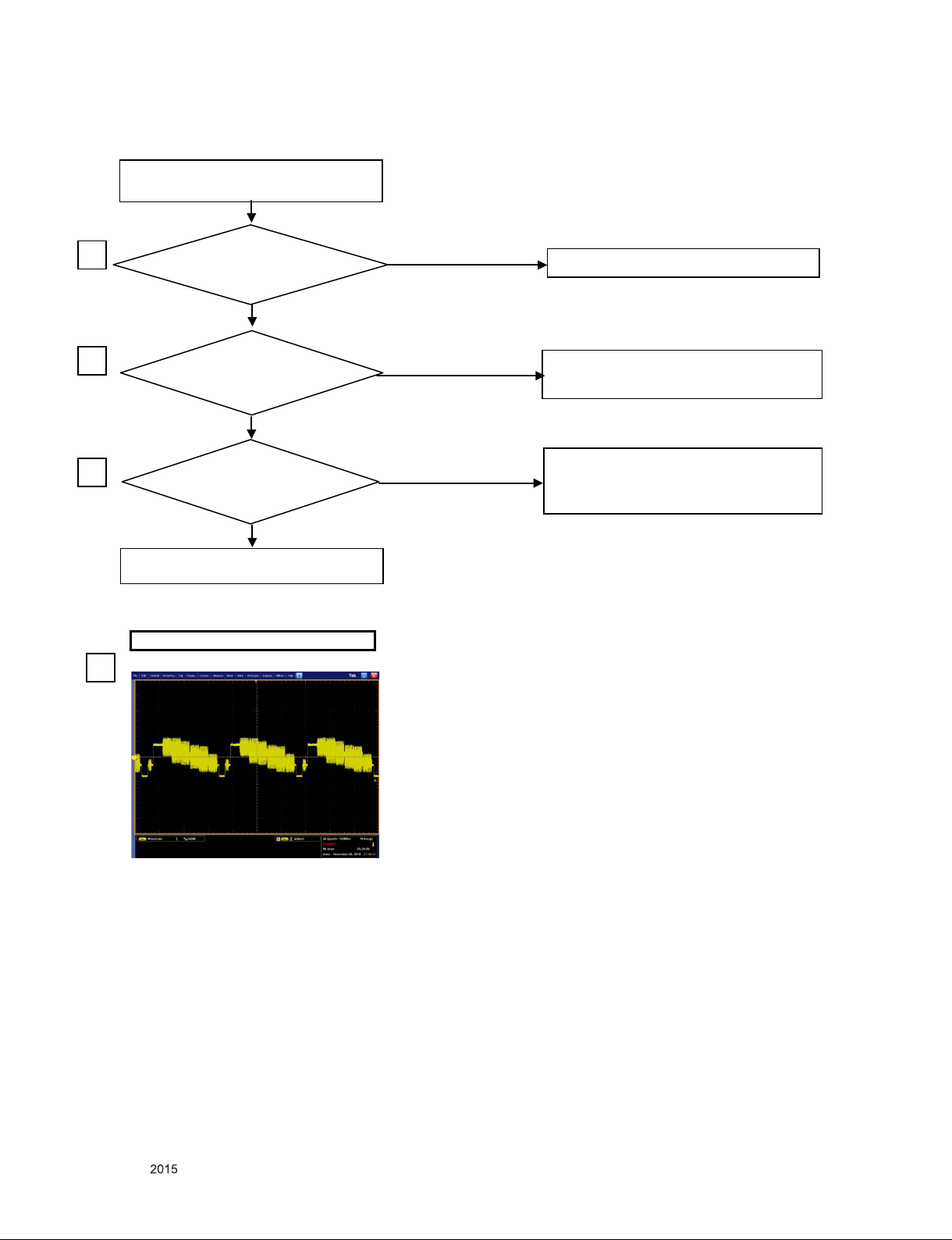
5. Abnormal screen (AV)-Main PCBA
Put into AV cable completely?
Abnormal screen (AV)
YES
NO
NO
Insult AV cable tight
1
Change IC501
WAVEFORMS
Is Input signal timing
and format in spec?
Change Timing to 480I, 576I
Or change format CVBS
2
Is waveform at R505
3
Check Line between JK101 and IC501
is open or short, Another is
change AV cable
NO
YES
YES
R505 (CVBS)
3
Copyright © LG Electronics. Inc. All right reserved.
Only for training and service purposes
- 17 -
LGE Internal Use Only
Page 18
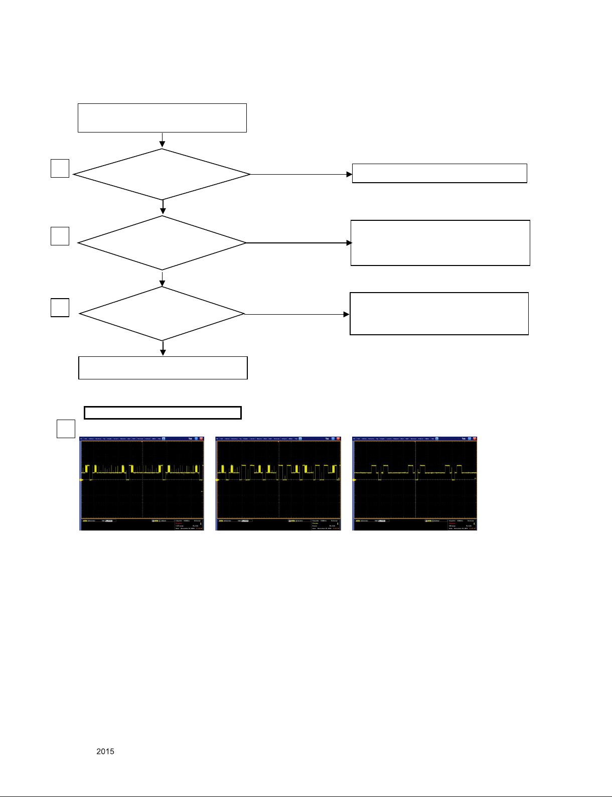
6. Abnormal screen (RGB PC)-Main PCBA
P u t i n to RGB
cable completely?
Ab normal screen (RGB PC)
YES
NO
NO
insult RGB cable tight
1
Change IC501
WAVE FORMS
Is Input signal timing
and format in s pec?
Change Timing acco rding to
product sp ec, Or change f ormat to RGB
2
Is wave form at R501
R502, R504
3
Check Line between JK201 and IC501
is op en or short, Another is
Change RGB cab le
NO
YES
YES
3
R502(G)
R604(R)
R601(B)
Copyright © LG Electronics. Inc. All right reserved.
Only for training and service purposes
- 18 -
LGE Internal Use Only
Page 19
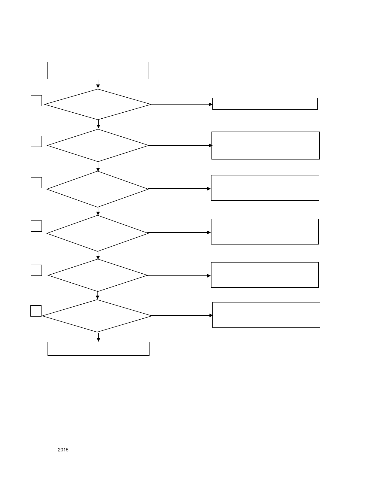
7. Abnormal screen (HDMI)-Main PCBA
P u t i n to HDMI
cable completely?
Ab normal screen (HDMI)
YES
NO
NO
insulted HDMI cable
1
Change IC501
Is Input signal timing
and format in s pec?
Change Timing acco rding to
product sp ec, change f ormat
under 8 bit in Ycbcr, Ypbpr, RGB
2
Is wave form at 10,12pin
of JK203?
3
Check Line between JK203 and IC501
is op en or short, Another is
Change HD MI cable
NO
YES
YES
Is waveform a t 1,3,4,6,7,9pin
Of JK203?
YES
4
Check Line between JK203 and IC501
is op en or short, Another is
Change HD MI cable
NO
Can read EDID and
HDCP key though
16,15pin of JK203
Check Line between JK203 and IC501
is op en or short, Another is
Change HD MI cab le
YES
Is 5V at 19pin of JK203?
Check Line between JK203 and IC501
is op en or short, Another is
Change IC501 or HDMI cable
5
YES
6
Copyright © LG Electronics. Inc. All right reserved.
Only for training and service purposes
- 19 -
LGE Internal Use Only
Page 20
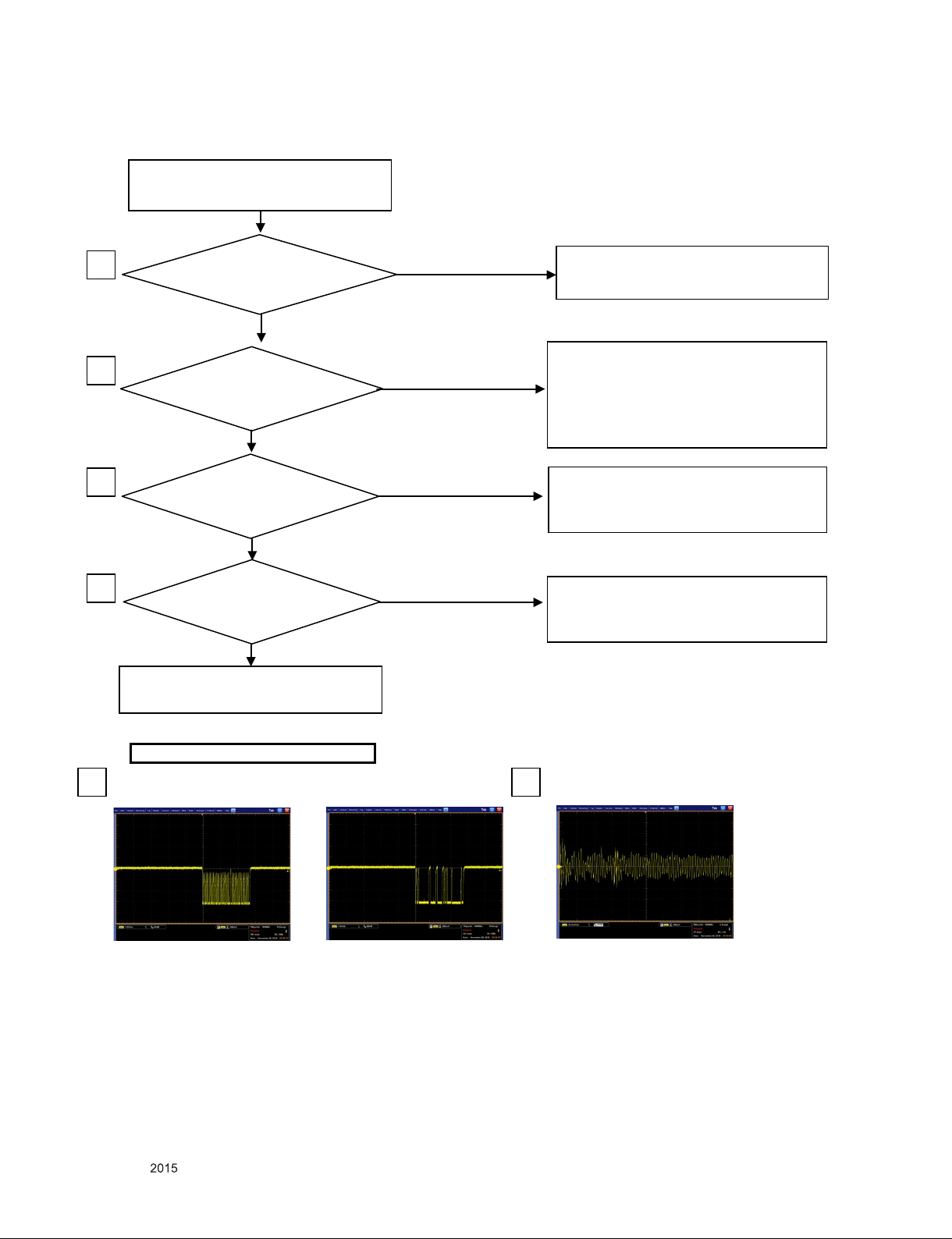
8. No sound (all source )-Main PCBA
Does wire connect P301 with speaker?
NO sound (All source)
YES
NO
YES
NO
YES
Connect wire between P301 and speaker.
1
Change speaker and wire
Is 19.4V at 19,20,31,32pin
of IC301 ?
If 8V is not plus at L703, check
of JK700 is open.
If is not Check Line between L703
and IC301 is open or short.
.Another is change IC301
2
NO
Is 3.3V at 40pin of IC301?
If 3V is not plus 30pin of IC301,
check It is over 3V at L301
if it is not, Check Line between L301
and IC301 is open or short.
Another is change IC701,IC301
NO
3
4
YES
Is I2C waveform at
10,11pin of IC301?
Check Line between IC301 and IC501
is open or short, Another is change
IC301 or IC501.
NO
5
Is I2S waveform at
R301,R302,R303,R304?
6
Check Line between IC301 and IC501
is open or short, Another is change
IC301 or IC501.
YES
Is there any waveform P301?
Check Line between IC301 and P301
is open or short. And then check resistance
of speaker is under 4ohm.
Another is change IC301
NO
4
10pin of IC301
11pin of IC301
5
R301(SDO)
R302(WS)
R303(SCK)
5
R304(MCLK)
6
1pin of P301(Audio out)
Copyright © LG Electronics. Inc. All right reserved.
Only for training and service purposes
- 20 -
LGE Internal Use Only
Page 21
9. Abnormal sound (TV)-Main PCBA
Put into RF cable completely?
Abnormal sound (TV)
YES
NO
insult RF cable tight and then
Cable nut screw tight.
1
2
3
4
NO
Change Main PCBA
WAVEFORMS
Is 1.8V at 7pin of TU401?
Is I2C waveform
At 3,4pin of TU401?
Is IF waveform at 43
,44 pin of IC501?
NO
NO
3
3Pin of TU401 (SCL)
4Pin of TU401 (SDA)
4
43,44pin of IC501
If 1.7V is not at plus pin of TU401, check
It is over 3V at 2pin of IC711,
if it is not, Check Line between TU401
and IC711 is open or short.
Another is change IC401 or TU401
Check Line between TU401 and IC501
is open or short, Another is change
IC501 or TU401
Check Line between TU401 and IC501
is open or short, Another is change
IC501 or TU401
Copyright © LG Electronics. Inc. All right reserved.
Only for training and service purposes
- 21 -
LGE Internal Use Only
Page 22
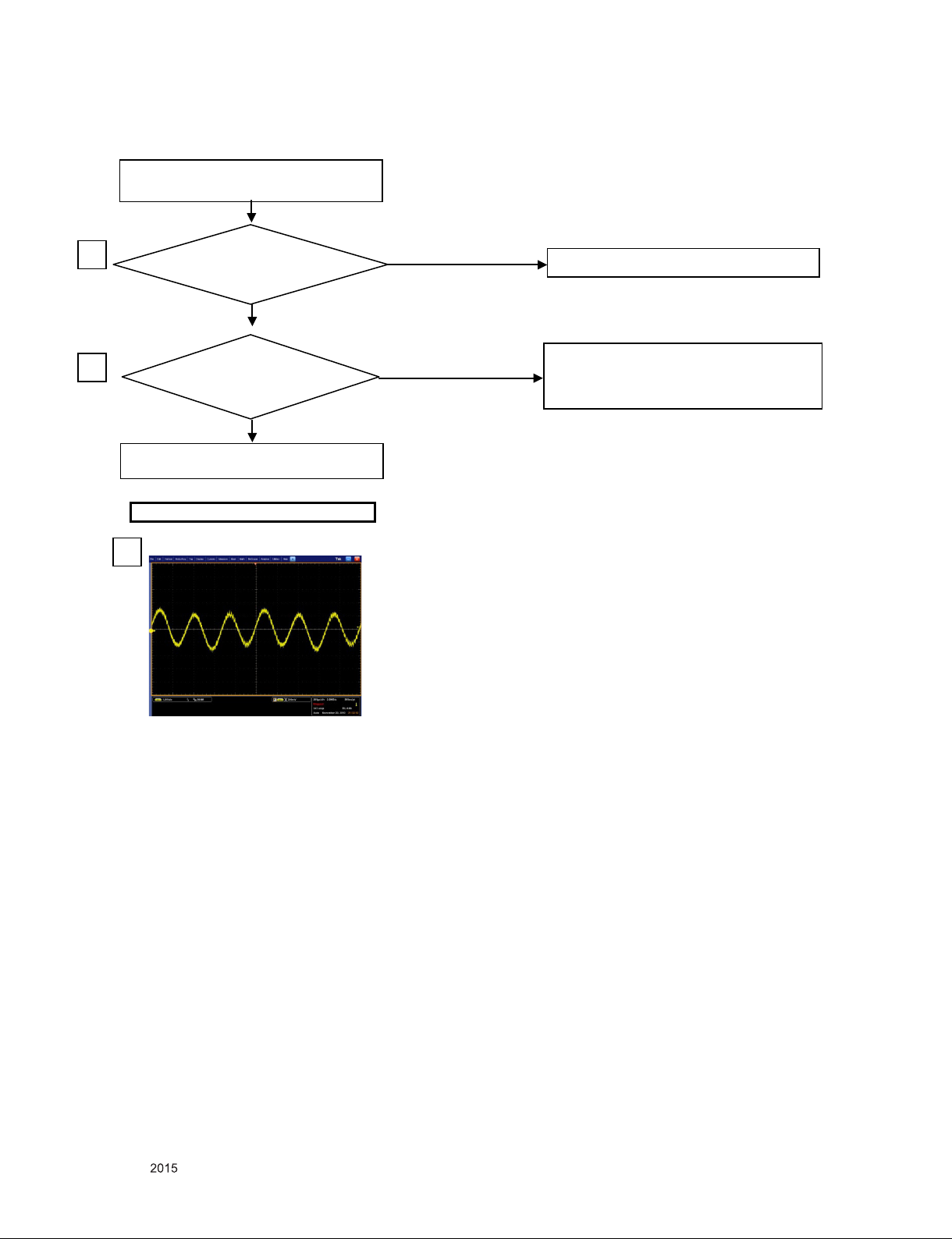
10. Abnormal sound (AV)-Main PCBA
Put into AV cable completely?
Abnormal sound (AV)
YES
NO
Insult AV cable tight
1
Change IC501
WAVEFORMS
Is waveform at C520,C521
2
Check Line between JK101 and IC501
is open or short, Another is
change AV cable
NO
YES
C520,C521(audio in)
2
Copyright © LG Electronics. Inc. All right reserved.
Only for training and service purposes
- 22 -
LGE Internal Use Only
Page 23
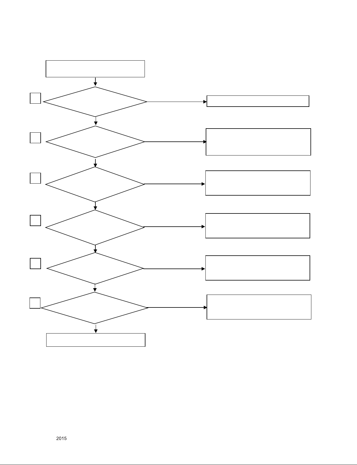
11. Abnormal sound (HDMI)-Main PCBA
Ab normal sound (HDMI)
P u t i n to HDMI
cable completely?
YES
NO
NO
insulted HDMI cable
1
Change IC501
Is Input signal timing
and format in s pec?
Change Timing acco rding to
product sp ec, change f ormat
under 8 bit in Ycbcr, Ypbpr, RGB
2
Is wave form at 10,12pin
of JK203?
3
Check Line between JK203 and IC501
is op en or short, Another is
Change HD MI cable
NO
YES
YES
Is waveform a t 1,3,4,6,7,9pin
Of JK203?
YES
4
Check Line between JK203 and IC501
is op en or short, Another is
Change HD MI cable
NO
Can read EDID and
HDCP key though
16,15pin of JK203
Check Line between JK203 and IC501
is op en or short, Another is
Change HD MI cab le
YES
Is 5V at 19pin of JK203?
Check Line between JK203 and IC501
is op en or short, Another is
Change IC501 or HDMI cable
5
YES
6
Copyright © LG Electronics. Inc. All right reserved.
Only for training and service purposes
- 23 -
LGE Internal Use Only
Page 24
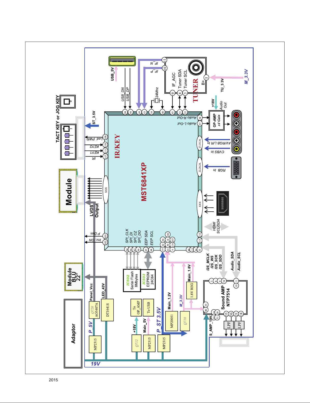
BLOCK DIAGRAM
Copyright © LG Electronics. Inc. All right reserved.
Only for training and service purposes
- 24 -
LGE Internal Use Only
Page 25
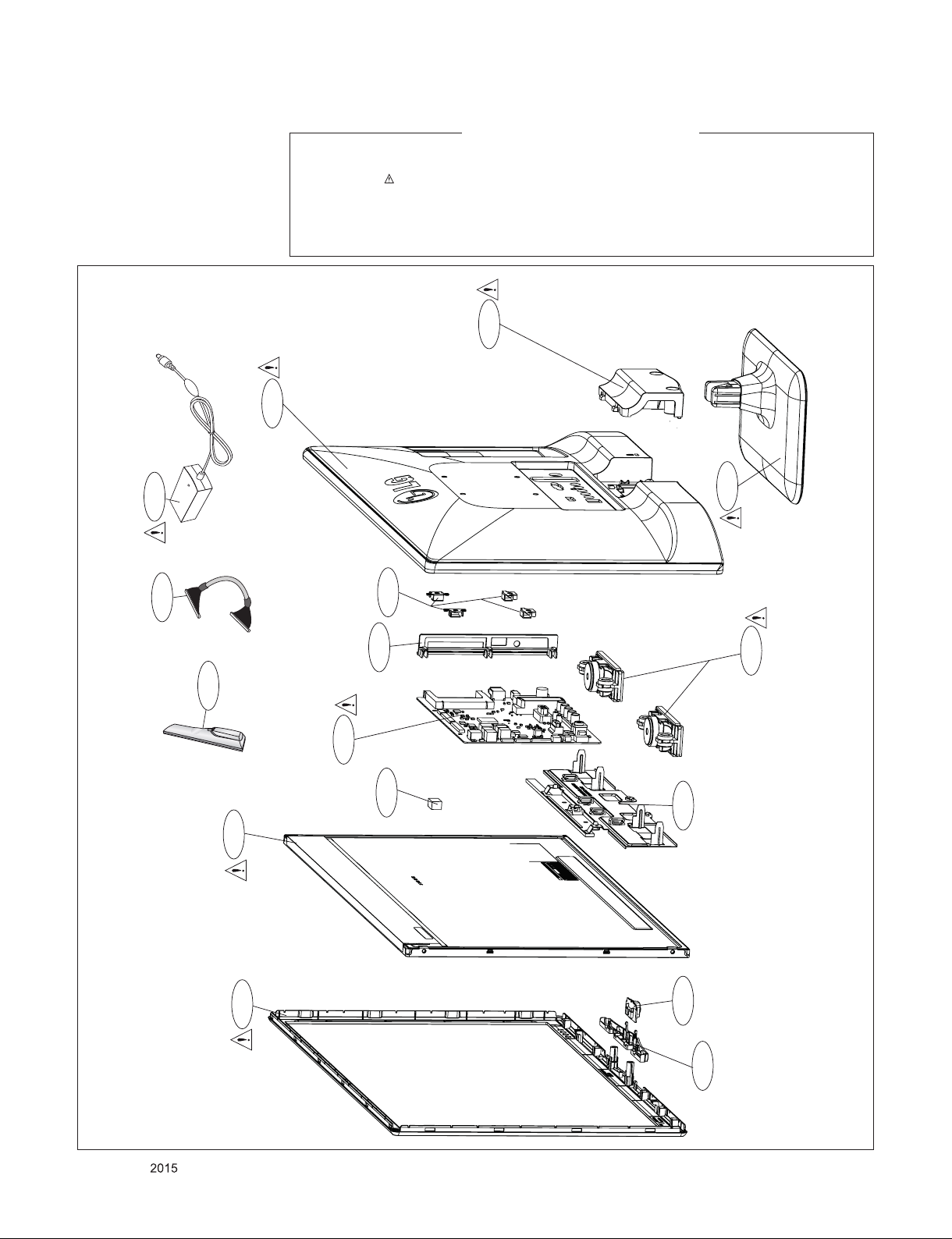
EXPLODED VIEW
IMPORTANT SAFETY NOTICE
Many electrical and mechanical parts in this chassis have special safety-related characteristics. These parts
are identified by in the Schematic Diagram and EXPLODED VIEW.
It is essential that these special safety parts should be replaced with the same components as recommended
in this manual to prevent Shock, Fire, or other Hazards.
Do not modify the original design without permission of manufacturer.
910
400
535
LV1
A2
200
540
401
820
810
900
120
800
300
Copyright © LG Electronics. Inc. All right reserved.
Only for training and service purposes
- 25 -
510
305
LGE Internal Use Only
Page 26
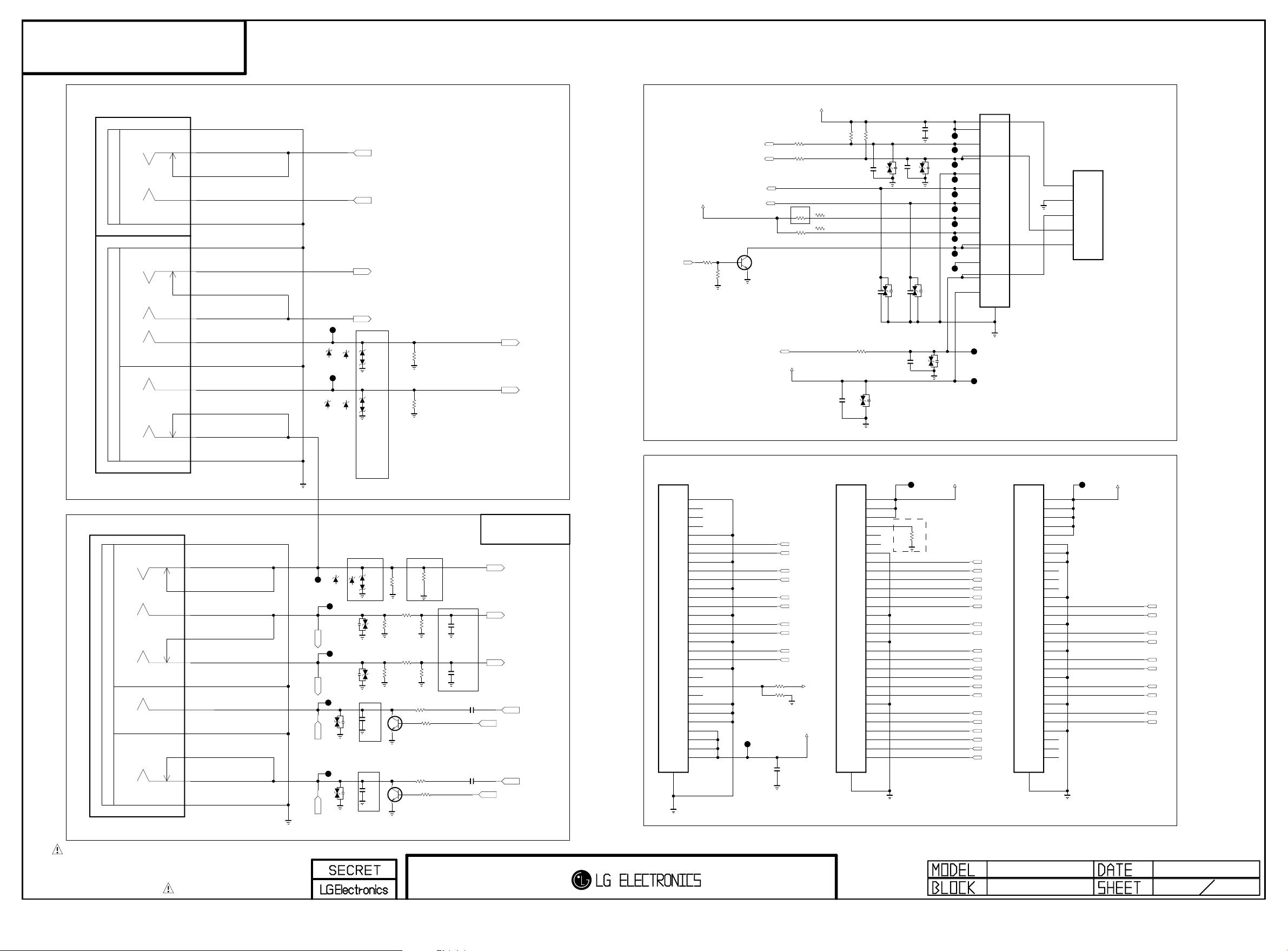
EAX65643103
Copyright ⓒ 2015 LG Electronics. Inc. All right reserved.
Only for training and service purposes
LGE Internal Use Only
44A/45A/450A
JK102
PPJ243-21
COMPONENT
[RD1]E-LUG
6B
[RD1]C-SPRING
5B
[RD1]CONTACT
4B
[WH1]C-SPRING
5A
[WH1]E-LUG
6A
[RD3]E-LUG
6G
[RD3]C-SPRING
5G
[RD3]CONTACT
4G
[WH2]C-SPRING
5F
[RD2]C-SPRING
5E
[RD2]E-LUG-S
7E
[BL]C-SPRING
5D
[GN/YL]CONTACT
4C
[GN/YL]C-SPRING
5C
JP108
5.6V
5.6V
ZD105-*1
ZD106-*1
COMPONENT_KDZ5.6V
COMPONENT_KDZ5.6V
JP107
5.6V
5.6V
ZD103-*1
ZD104-*1
COMPONENT_KDZ5.6V
COMPONENT_KDZ5.6V
ROUT
LOUT
RIN
LIN
COMPONENT_UDZS5.6B
ZD105
SD05
ZD106
SD05
COMPONENT_UDZS5.6B
COMPONENT_UDZS5.6B
ZD103
SD05
ZD104
SD05
COMPONENT_UDZS5.6B
COMPONENT/AV_IN/OUT
COMPONENT
R145
75
COMPONENT
R146
75
COMMON_R
COMMON_B
CONTROL Key
IR & LED
+3.5V_ST
R126
10K
READY
R127
10K
B
LED_B
KEY1
KEY2
EEP_SCL
EEP_SDA
LED_MT45_270ohm
C
Q120
MMBT3904(NXP)
E
IR
+3.5V_ST
R122
100
R123
100
2013.10.18 CJLIM
LED current setting
R124-*2
R124
100
270
R124-*1
READY
680
R125
100
+3.5V_ST
R120
3.3K
C120
0.1uF
16V
LED_MT44_100ohm
LED_LB45_680ohm
R130
100
C125
4.7uF
10V
R121
3.3K
C122
READY
D124
5.6V
50V
100pF
20V
D126
C121
0.1uF
20V
D120
C123
READY
16V
50V
100pF
C124
1000pF
50V
20V
D127
C126
4.7uF
10V
D121
45A/450A
P120
12507WR-12L
1
JP120
2
JP121
3
JP122
20V
20V
D123
JP123
JP124
JP125
JP126
JP127
JP128
JP129
4
5
6
7
8
9
10
11
12
13
JP130
JP131
44A
P121
SMAW200-05
1
2
3
4
5
JK101
PPJ234-03
[GN/YL]E-LUG
6C
Composite Jack
[YL]E-LUG
6E
[YL]O-SPRING
5E
[YL]CONTACT
4E
[WH2]O-SPRING
5D
[RD2]CONTACT
4C
[RD2]O-SPRING
5C
[RD2]E-LUG-S
7C
[WH1]O-SPRING
5B
[WH1]E-LUG-S
7B
[RD1]CONTACT
4A
[RD1]O-SPRING
5A
[RD1]E-LUG
6A
12.12.19. ESD(Add zenerDiode)
12.12.18 : ESD(Add to zener diode)
UDZS5.6B
ZD101
KDZ5.6V
JP101
5.6V
ZD102-*2
SD05
ZD102
SD05
UDZS5.6B
D103
20V
JP103
5.6V
ZD101-*1
KDZ5.6V
LIN
JP102
D102
20V
RIN
JP104
C103
D104
1000pF
20V
50V
LOUT
To improve EMS S2a issue.
2013.11.27 by BJ.KIM
JP105
C105
D105
1000pF
20V
50V
ROUT
READY
R147
R101
75
75
1/4W
Size Check~!!! 3216 size..
R106
10K
R103
10K
C
B
E
Q101
MMBT3904(NXP)
C
B
E
Q103
MMBT3904(NXP)
R108
1K
R109
1K
R112
3.9K
R113
3.9K
R107
12K
R104
12K
R105
220K
R102
220K
To improve EMS S2a issue.
2013.11.27 by BJ.KIM
C102
1000pF
50V
EMS Improve(12.12.28)
C101
1000pF
50V
C10 4
10u F
10V
C10 6
10u F
10V
AV_IN/OUT
COMMON_VIN
AUDIO_LIN
READY -> 1000PF
AUDIO_RIN
MUTE_AOUT
POP NOISE
MUTE_AOUT
POP NOISE
MNT_LOUT
MNT_ROUT
MODULE_HD
P101
10031HR-30
31
MODULE_FHD
LVDS
1
2
3
4
5
6
7
8
9
10
11
12
13
14
15
16
17
18
19
20
21
22
23
24
25
26
27
28
29
30
JP110
READY
R110
10K
R111
10K
READY
C112
10uF
16V
RXA3+
RXA3-
RXACK+
RXACK-
RXA2+
RXA2-
RXA1+
RXA1-
RXA0+
RXA0-
+3.3V_M
PANEL_VCC
P102
10031HR-30
31
PANEL_VCC
JP111
1
2
3
4
5
6
7
8
9
10
11
12
13
14
15
16
17
18
19
20
21
22
23
24
25
26
27
28
29
30
INTERLACE MODE
22inch FHD IPS
Change Option Name.(22LN4300 -> 22LB)
-. TN FHD : PWM OUT(If not use : NC)
R100
-. IPS FHD : Interlace(If not use : GND)
0
RXA3+
RXA3-
RXACK+
RXACK-
RXA2+
RXA2-
RXA1+
RXA1-
RXA0+
RXA0-
RXB3+
RXB3-
RXBCK+
RXBCK-
RXB2+
RXB2-
RXB1+
RXB1-
RXB0+
RXB0-
RXA3+
RXA3RXACK+
RXACKRXA2+
RXA2-
RXA1+
RXA1-
RXA0+
RXA0RXB3+
RXB3RXBCK+
RXBCK-
RXB2+
RXB2RXB1+
RXB1RXB0+
RXB0-
MODULE_HD_18.5
P103
10031HR-30
10
11
12
13
14
15
16
17
18
19
20
21
22
23
24
25
26
27
28
29
30
31
PANEL_VCC
JP112
1
2
3
4
5
6
7
8
9
RXA3+
RXA3-
RXACK+
RXACK-
RXA2+
RXA2-
RXA1+
RXA1-
RXA0+
RXA0-
THE SYMBOL MARK OF THIS SCHEMETIC DIAGRAM INCORPORATES
SPECIAL FEATURES IMPORTANT FOR PROTECTION FROM X-RADIATION.
FIRE AND ELECTRICAL SHOCK HAZARDS, WHEN SERVICING IF IS
ESSENTIAL THAT ONLY MANUFACTURES SPECIFIED PARTS BE USED FOR
THE CRITICAL COMPONENTS IN THE SYMBOL MARK OF THE SCHEMETIC.
INPUT1/LVDS
44A/45A/450A
INPUT1/LVDS
2013/08/21
1 8
Page 27
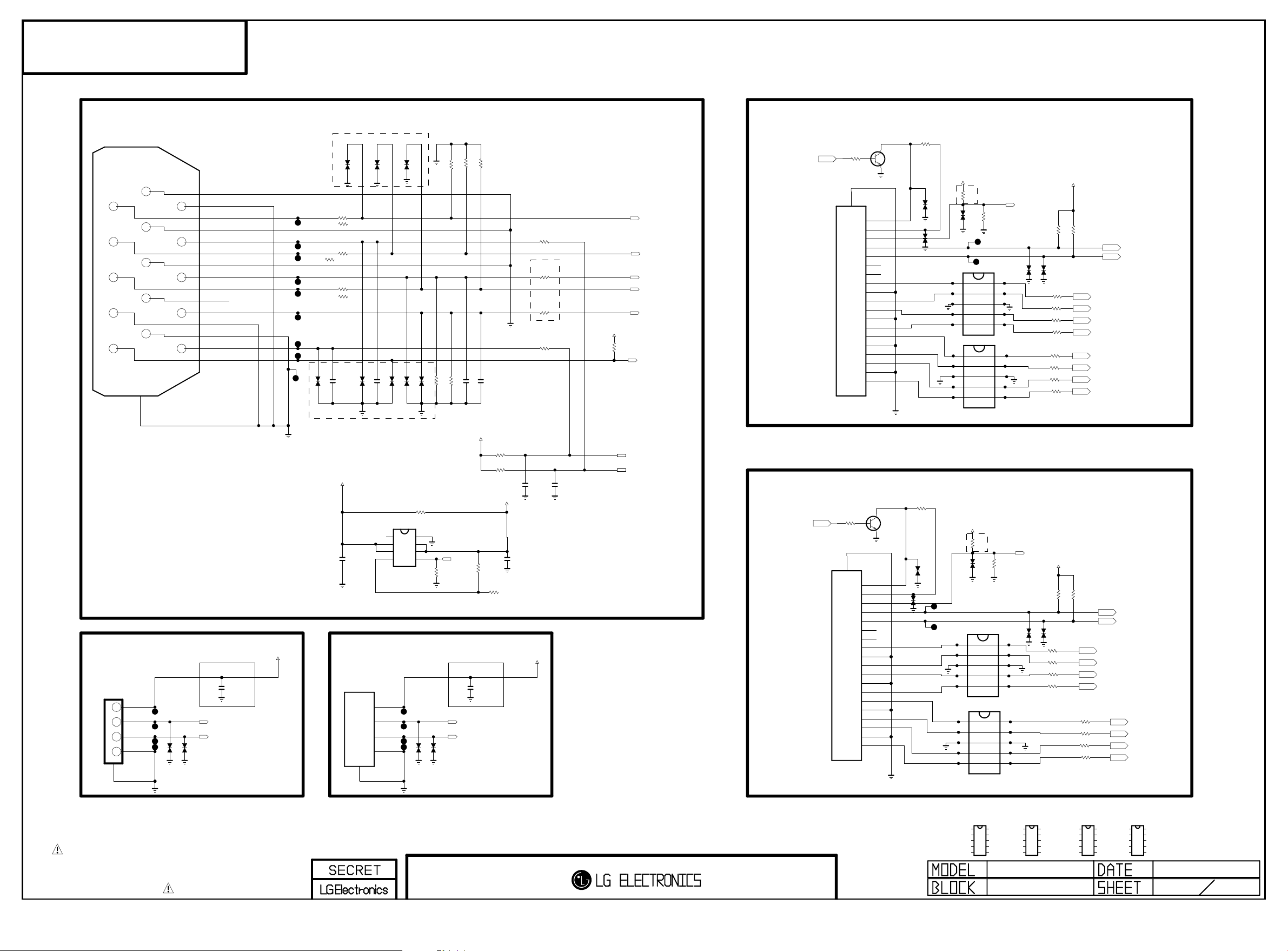
EAX65643103
Copyright ⓒ 2015 LG Electronics. Inc. All right reserved.
Only for training and service purposes
LGE Internal Use Only
44A/45A/450A
JK201
SPG09-DB-010
6
1
11
7
2
12
8
3
13
9
4
14
10
5
1.RED
2.GRN
3.BLU
4.NC
5.ST-DET
7.GNC
8.B_GND
9.G_GND
10.R_GND
11.GND
12.SDA
13.HSYNC
14.VSYNC
15.SCL
16
SHILED
15
SIDE USB
SIDE_USB
3AU04S-305-ZC-(LG)
JK202
1234
USB DOWN STREAM
5
JP211
JP208
JP209
JP210
READY
ZD220
READY
ZD221
RGB
RED_GND
GND_2
RED
GREEN_GND
DDC_DATA
GREEN
BLUE_GND
H_SYNC
BLUE
NC
V_SYNC
GND_1
SYNC_GND
DDC_CLOCK
DDC_GND
Close to SIDE_USB
SIDE_USB
C221
22uF
6.3V
SIDE_USB_DN
SIDE_USB_DP
JP220
JP226
JP227
JP228
+5V_USB_OUT
JP225
JP221
JP222
JP223
JP224
EAH39491601 -> EAF61771401
2013.11.27 by BJ.KIM
RGB
RGB
D201
D202
RGB
R214
15
COMPONENT
R214-*1
0
RGB
R215
15
COMPONENT
R215-*1
0
RGB
R216
15
COMPONENT
R216-*1
0
READY
C201
68pF
50V
READY
C202
68pF
D205
D206
D204
50V
RGB
EAH39491601 -> EAF61771401
2013.11.27 by BJ.KIM
+5V_USB_OUT
NC
OUT_2
C200
0.1uF
16V
OUT_1
FLG
REAR USB
REAR_USB
JK205
US-04A-VSD
1
2
3
JP253
4
5
RGB
NON_USB_OCP
IC200
AP2191DSG
8
USB_OCP
7
6
5
1
2
3
4
JP250
JP251
JP252
D203
D207
RGB
2012
R217
0
GND
IN_1
IN_2
EN
READY
ZD222
D208
RGB
R21 2 22 K
RGB
R218
READY
ZD223
RGB
RGB
91
R20 1
91
R21 3 22 K
C203 68pF
RGB
RGB
USB_CTL
4.7K
READY
Close to SIDE_USB
REAR_USB
REAR_USB_DN
REAR_USB_DP
R20 2
+5V_USB
R200
10K
C222
22uF
6.3V
RGB
R20 3
91
GND_R
GND_G
GND_B
C204 68pF
RGB
R211
47
R210
4.7K
R209
4.7K
+5V_USB
2013.05.30 CJ.LIM
READY
C205
18pF
50V
C207
0.1uF
16V
+5V_USB_OUT
R204
33
RGB
R205
RGB
R206
R207
33
READY
18pF
33
33
C206
50V
+3.3V_ST
RGB
R208
10K
COMMON_R
DSUB_G
DSUB_HSYNC
COMMON_B
DSUB_VSYNC
DSUB_DET
DSUB_SCL
DSUB_SDA
HDMI2
HDMI1_HPD
HDMI1
HDMI2_HPD
HDMI2
SHIELD
JK203
HDMI2
HDMI1
R241
10K
SHIELD
20
JK204
HDMI1
R230
10K
20
10
19
18
17
16
15
14
13
12
11
10
9
8
7
6
5
4
3
2
1
C
B
E
HPD
19
+5V_POWER
18
DDC/CEC_GND
17
SDA
16
SCL
15
NC
14
CEC
13
CLK-
12
CLK_SHIELD
11
CLK+
DATA0-
9
DATA0_SHIELD
8
DATA0+
7
DATA1-
6
DATA1_SHIELD
5
DATA1+
4
DATA2-
3
DATA2_SHIELD
2
DATA2+
1
C
HDMI1
B
Q240
MMBT3904(NXP)
E
HPD
+5V_POWER
DDC/CEC_GND
SDA
SCL
NC
CEC
CLKCLK_SHIELD
CLK+
DATA0DATA0_SHIELD
DATA0+
DATA1-
DATA1_SHIELD
DATA1+
DATA2DATA2_SHIELD
DATA2+
Q230
MMBT3904(NXP)
HDMI2
D247
HDMI2
R231
1K
D231
D248
HDMI1
R242
1K
HDMI1
D241
READY
EAH39491601 -> EAF61771401
2013.11.27 by BJ.KIM
To improve HDMI Detect speed.(OPT(HDMI2)->Apply)
2013.11.27 by BJ.KIM
+3.5V_ST
10K
OPT
R235
HDMI2
READY
JP206
JP207
D209
ESD_HDMI2_IP4283
TMDS_CH1-
TMDS_CH1+
GND_1
TMDS_CH2-
TMDS_CH2+
TMDS_CH1-
TMDS_CH1+
GND_1
TMDS_CH2-
TMDS_CH2+
+3.5V_ST
D246
TMDS_CH1-
TMDS_CH1+
GND_1
TMDS_CH2-
TMDS_CH2+
TMDS_CH1-
TMDS_CH1+
GND_1
TMDS_CH2-
TMDS_CH2+
READY
JP204
JP205
D234
IP4283CZ10-TBA
1
2
3
4
5
D235
ESD_HDMI2_IP4283
IP4283CZ10-TBA
1
2
3
4
5
10K
R816
READY
ESD_HDMI1_IP4283
D244
IP4283CZ10-TBA
1
2
3
4
5
ESD_HDMI1_IP4283
D245
IP4283CZ10-TBA
1
2
3
4
5
10
OPT
R220
HDMI1_DET
0
R219
D232
HDMI2
NC_4
NC_3
9
GND_2
8
NC_2
7
NC_1
6
NC_4
10
NC_3
9
GND_2
8
NC_2
7
NC_1
6
EAH39491601 -> EAF61771401
2013.11.27 by BJ.KIM
To improve HDMI Detect speed.(OPT(HDMI1)->Apply)
2013.11.27 by BJ.KIM
0
HDMI1
D242
NC_4
10
NC_3
9
GND_2
8
NC_2
7
NC_1
6
NC_4
10
NC_3
9
GND_2
8
NC_2
7
NC_1
6
HDMI2_DET
HDMI1
HDMI1
HDMI1
+5V_USB
HDMI2
HDMI2
R233
R232
2.7K
2.7K
D233
EAH39491601 -> EAF61771401
HDMI2
2013.11.27 by BJ.KIM
HDMI2
R253
5.6
HDMI2
R254
5.6
HDMI2
R255
5.6
HDMI2
R256
5.6
HDMI2
R257
5.6
HDMI2
R258
5.6
HDMI2
R259
5.6
HDMI2
R260
5.6
+5V_USB
HDMI1
HDMI1
R243
R244
2.7K
2.7K
HDMI1
D243
R245
5.6
R246
5.6
HDMI1
R247
5.6
R248
5.6
HDMI1
R249
5.6
HDMI1
R250
5.6
HDMI1
R251
5.6
HDMI1
R252
5.6
HDMI1_SDA
HDMI1_SCL
HDMI1_CKHDMI1_CK+
HDMI1_D0HDMI1_D0+
HDMI1_D1HDMI1_D1+
HDMI1_D2HDMI1_D2+
HDMI2_SDA
HDMI2_SCL
HDMI2_CKHDMI2_CK+
HDMI2_D0HDMI2_D0+
HDMI2_D1HDMI2_D1+
HDMI2_D2HDMI2_D2+
THE SYMBOL MARK OF THIS SCHEMETIC DIAGRAM INCORPORATES
SPECIAL FEATURES IMPORTANT FOR PROTECTION FROM X-RADIATION.
FIRE AND ELECTRICAL SHOCK HAZARDS, WHEN SERVICING IF IS
ESSENTIAL THAT ONLY MANUFACTURES SPECIFIED PARTS BE USED FOR
THE CRITICAL COMPONENTS IN THE SYMBOL MARK OF THE SCHEMETIC.
INPUT2
ESD_HDMI2_IP4294
D234-*1
IP4294CZ10-TBR
1
10
2
9
3
8
7
4
6
5
ESD_HDMI2_IP4294
D235-*1
IP4294CZ10-TBR
1
10
2
9
3
8
7
4
6
5
44A/45A/450A
INPUT2
ESD_HDMI1_IP4294
D244-*1
IP4294CZ10-TBR
1
10
2
9
3
8
7
4
6
5
ESD_HDMI1_IP4294
D245-*1
IP4294CZ10-TBR
1
10
2
9
3
8
7
4
6
5
2013/08/21
2 8
Page 28
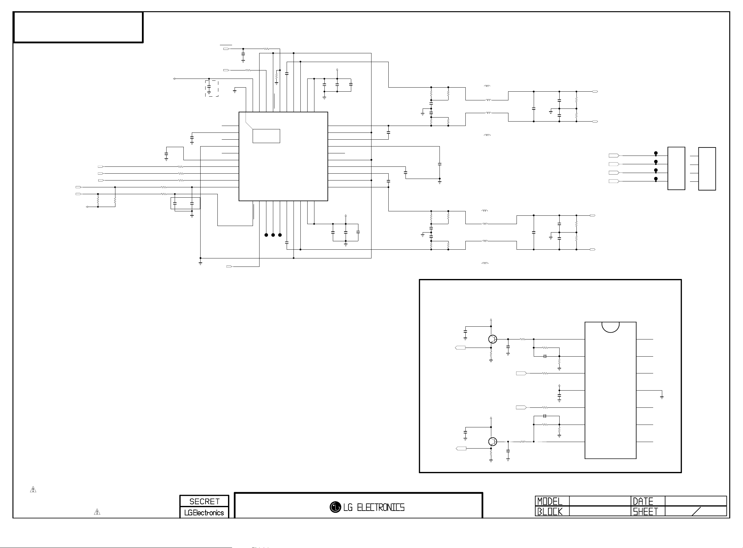
EAX65643103
Copyright ⓒ 2015 LG Electronics. Inc. All right reserved.
Only for training and service purposes
LGE Internal Use Only
44A/45A/450A
AUAMP_SDA
AUAMP_SCL
+3.3V_M
I2S_SDO
I2S_WS
I2S_SCK
R308
4.7K
R309
4.7K
R305 100
R306 100
20130914 cjlim
READY -> APPLY
+3.3V_M
To improve CST issue.(X5R -> X7R)
EAE31360401->EAE52158501
2013.11.27
C301
1uF
10V
C303
1uF
10V
R301 100
R302 100
R303 100
C305
C306
33pF
33pF
50V
50V
SW_RESET
C321
10uF
10V
NC_1
VDD_PLL
NC_2
NC_3
DVDD
SDATA
POWER_DET
I2S_MCLK
GND
WCK
BCK
SDA
C320
1000pF
50V
R304 100
R310 100
VDD_IO
[EP]GND
40
1
2
THERMAL
3
4
5
6
7
8
9
10
11
SCL
AD
CLK_I
GND_IO
37
38
39
41
NTP7514
12
13
14
FAULT
MONITOR_0
MONITOR_1
50V
C319
22000pF
R311 4.7K
BST1A
RESET
35
36
IC301
0x54
15
16
BST2B
MONITOR_2
C308
22000pF
50V
OUT1A
PGND1A
33
34
17
18
OUT2B
PGND2B
PVDD1B
PVDD1A
31
32
30
29
28
27
26
25
24
23
22
21
19
PVDD2B20PVDD2A
+19V
C318
0.1uF
25V
OUT1B
PGND1B
BST1B
VDR1
NC_4
AGND
VDR2
BST2A
PGND2A
OUT2A
C30 9
0.1 uF
C317
10uF
25V
+19V
25V
C310
10uF
25V
READY
C348
10uF
25V
READY
C349
10uF
25V
C315
22000pF
50V
C311
22000pF
50V
C31 2
1uF
10V
R313
12
C325
390pF
50V
C326
390pF
50V
R315
12
R317
12
C327
390pF
50V
C328
390pF
50V
R319
12
C314
1uF
10V
R314
R316
R318
R320
TAIYO YUDEN
L303-*1
10.0uH
ABCO
12
12
12
12
L303
10uH
ABCO
L304
10uH
TAIYO YUDEN
L304-*1
10.0uH
TAIYO YUDEN
L305-*1
10.0uH
ABCO
L305
10uH
ABCO
L306
10uH
TAIYO YUDEN
L306-*1
10.0uH
C329
0.47uF
50V
C333
0.47uF
50V
C330
0.1uF
50V
C331
0.1uF
50V
C334
0.1uF
50V
C335
0.1uF
50V
R322
4.7K
R323
4.7K
R324
4.7K
R325
4.7K
SPK_L+
SPEAKER_L
SPK_L-
SPK_L+
SPK_LSPK_R+
SPK_R-
SPK_R+
SPEAKER_R
SPK_R-
JP304
JP303
JP302
JP301
SPK_L+
SPK_L-
SPK_R+
SPK_R-
4
3
2
1
.
SMAW250-H04R
P301
Non Box type
4
3
2
1
250A1-WR-H04M
P301-*1
Box type
AUDIO_OUT AMP : GAIN X 4
IC341
AS324MTR-E1
MNT_LOUT
MNT_ROUT
C341
0.1uF
25V
C346
0.1uF
25V
+18V
Q341
MMBT3904(NXP)
C
B
E
R341
4.7K
MNT_L_AMP
MNT_R_AMP
+18V
Q342
MMBT3904(NXP)
C
B
E
R34 8
4.7 K
R342 1K
C342
0.0068uF
50V
R349
C347
0.0068uF
50V
1K
10K
R343
33pF 50V
C343
R345 5.6K
R346 5.6K
33pF
C345
R347
10K
+18V
50V
R344
6.8K
C344
0.1uF
25V
R350
6.8K
1 OUT1
2 INPUT1-
3 INPUT1+
4 VCC
5 INPUT2+
6 INPUT2-
7 OUT2 8OUT3
14OUT4
13INPUT4-
12INPUT4+
11GND
10INPUT3+
9INPUT3-
THE SYMBOL MARK OF THIS SCHEMETIC DIAGRAM INCORPORATES
SPECIAL FEATURES IMPORTANT FOR PROTECTION FROM X-RADIATION.
FIRE AND ELECTRICAL SHOCK HAZARDS, WHEN SERVICING IF IS
ESSENTIAL THAT ONLY MANUFACTURES SPECIFIED PARTS BE USED FOR
THE CRITICAL COMPONENTS IN THE SYMBOL MARK OF THE SCHEMETIC.
AUDIO
44A/45A/450A
AUDIO
2013/08/21
3 8
Page 29
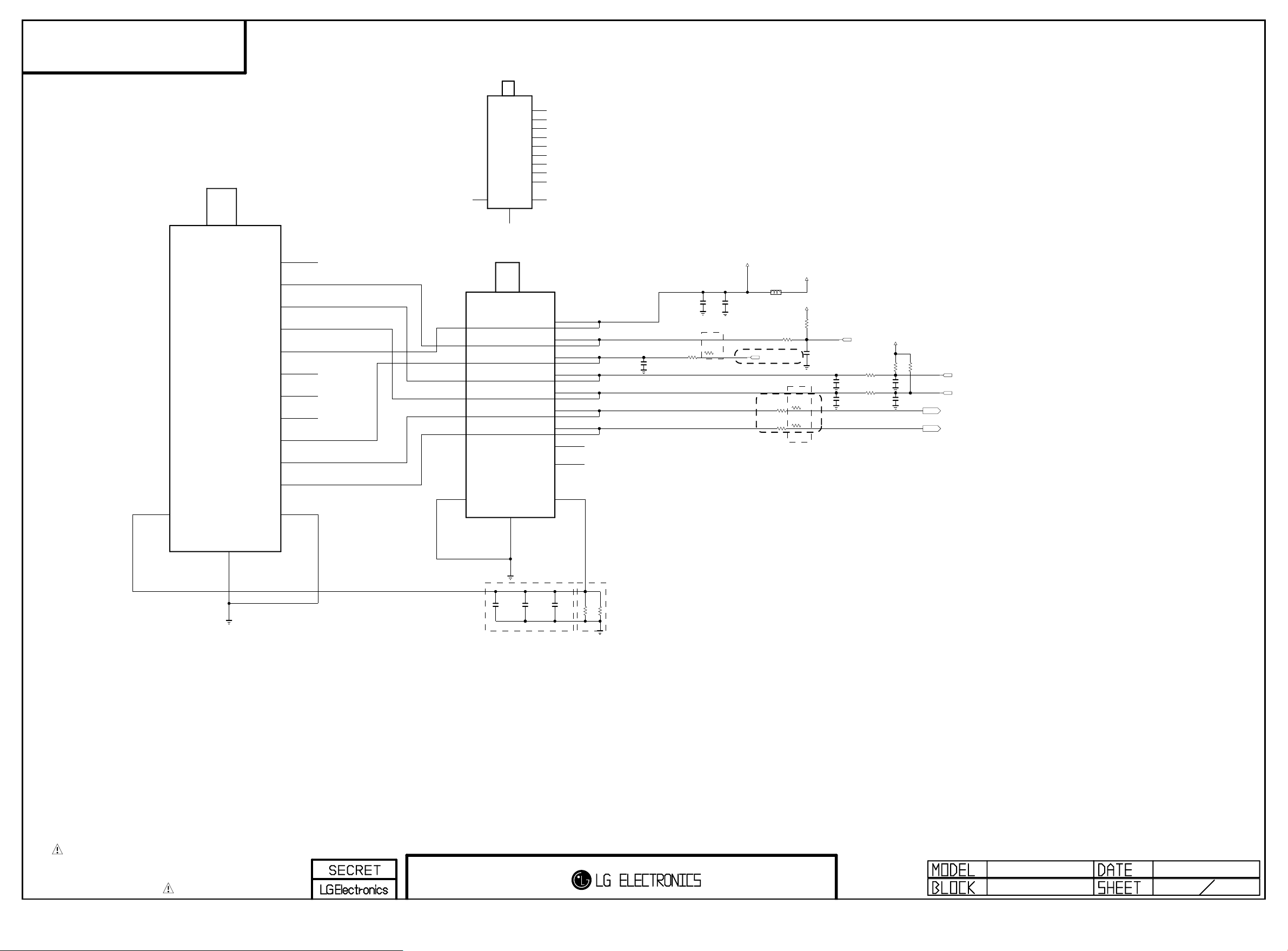
TBD
Copyright ⓒ 2015 LG Electronics. Inc. All right reserved.
Only for training and service purposes
LGE Internal Use Only
44A/45A/450A
IF
NTSC
TU402
TDSS-H701F
TU401-*1
TDJH-G301D
+3.3V
Y15_PAL_TUNER
1
NC_1
2
IF_AGC
3
SCL_RF
4
SDA_RF
5
IF[P]
6
IF[N]
7
SIF
8
CVBS
9
A1
A1
47
SHIELD
B1
B1
B1
B1
12
1
2
3
4
5
6
7
8
9
10
11
A1
NC_1
NC_2
SCL
SDA
+B1[3.3V]
NC_3
NC_4
NC_5
IF_AGC
DIF[P]
DIF[N]
A1
A1
A1
47
SHIELD
MULTI_TUNER
TU401
TDJH-G101D
B1[+3.3V]
1
NC_1
2
IF_AGC
3
SCL
4
SDA
5
IF[P]
6
IF[N]
7
NC_2
8
NC_3
9
B1
B1
Near the pin
To set multi option for NTSC
2013.11.27 by BJ.KIM
R412
100
should be guarded by ground
C410
0.1uF
16V
TUNER
PAL
TUNER
R412-*1
1K
C405
0.1uF
16V
NTSC
TUNER
C404
22uF
6.3V
+3.3V_TU
+3.3V_M
TUNER
L401
BLM18PG121SN1D
+3.3V_TU
READY
R404
100K
READY
R403
100
READY
C401
0.1uF
IF_AGC
PAL
R413
10
PAL
R414
10
Close to the tuner
16V
TUNER
C402
20pF
50V
TUNER
NTSC
R413-*1
33
NTSC
R414-*1
33
To change the value from 0ohm to 33ohm at NTSC.
2013.11.27 by BJ.KIM
C403
20pF
50V
TUNER
TUNER
+3.3V_TU
R407
1K
33
33
TUNER_RESET
R415
R416
TUNER
C406
20pF
50V
READY
C407
20pF
50V
READY
R408
1K
TUNER
TUNER_SCL
TUNER_SDA
IF_P
IF_N
SHIELD
THE SYMBOL MARK OF THIS SCHEMETIC DIAGRAM INCORPORATES
SPECIAL FEATURES IMPORTANT FOR PROTECTION FROM X-RADIATION.
FIRE AND ELECTRICAL SHOCK HAZARDS, WHEN SERVICING IF IS
ESSENTIAL THAT ONLY MANUFACTURES SPECIFIED PARTS BE USED FOR
THE CRITICAL COMPONENTS IN THE SYMBOL MARK OF THE SCHEMETIC.
TUNER
PAL
PAL
C411
C414
1000pF
1000pF
630V
630V
To improve RF Noise issue.(
Apply -> Only use Asis Model
PAL
C413
1000pF
630V
To improve RF Noise issue.
READY -> Only use NTSC
Size Up
1608->2012
R402
R401
NTSC
NTSC
0
0
)
44A/45A/450A
TUNER & IR
2013/08/21
4 8
Page 30
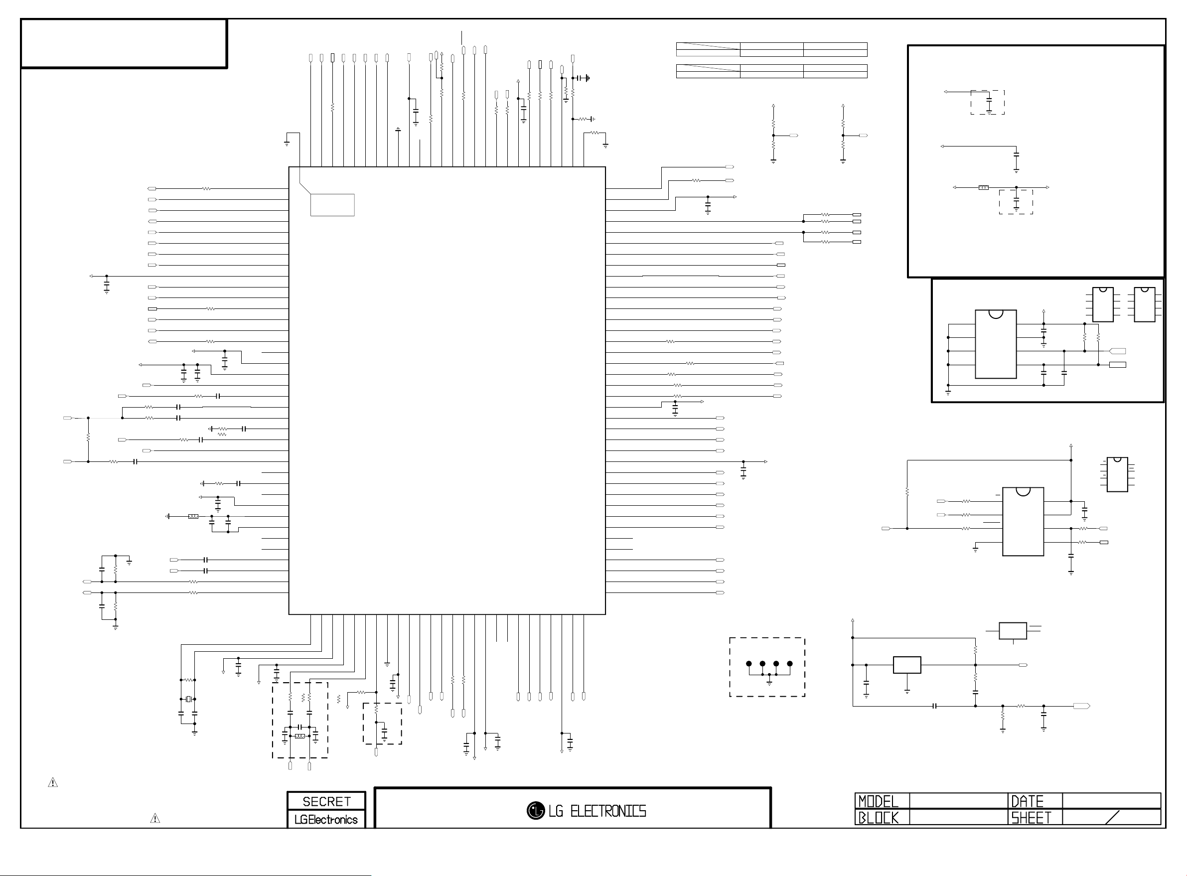
TBD
Copyright ⓒ 2015 LG Electronics. Inc. All right reserved.
Only for training and service purposes
LGE Internal Use Only
HDMI1_SDA
HDMI1_D0+
HDMI1_D1-
TUNER
[EP]
1
2
3
4
5
6
7
8
9
10
11
12
13
14
15
16
17
18
19
20
21
22
23
24
25
26
27
28
29
30
31
32
33
34
35
36
37
38
R513-*1
READY
C551
220pF
50V
L521
100NH
READY
IF_P
NTSC
0
HDMI1_D1+
33
HDMI2
R528
RX0P_D
DDCDD_DA
RX1N_D
RX1P_D
125
126
127
128
THERMAL
129
LGE6841 (ATV_13)
39
41
42
XTALO40XTALI
AVDD3P3_DADC
AVDD3P3_DMPLL
PAL
NTSC
R514
100
R514-*1
0
C535
0.1uF
+3.3V_M
TUNER
PAL
C537
33pF
Close to MSTAR
IF_N
44A/45A/450A
HDMI2
R500
RGB/COMPONENT
R501
C509
1000pF
RGB/COMPONENT
C510
0.047uF
R504
33
0.047uF
33
R505
33
HDMI1
R824
33
HDMI1
C507
0.1uF
33
RGB/COMPONENT
RGB/COMPONENT
C550
C506
0.1uF
C508
0.047uF
DSUB_G
COMMON_VIN
+3.3V_ST
COMPONENT
R515
0
C505
0.1uF
COMMON_B
COMMON_R
DSUB_HSYNC
DSUB_VSYNC
R506
33
HDMI1_SCL
HDMI1_D2-
HDMI1_D2+
HDMI2_HPD
HDMI2_CK-
HDMI2_CK+
HDMI2_D0-
HDMI2_D0+
HDMI2_D1-
HDMI2_D1+
HDMI2_SDA
HDMI2_D2-
HDMI2_D2+
HDMI2_SCL
+3.3V_ST
RGB/COMPONENT
RGB/COMPONENT
C513
0.047uF
R523
470
R502
33
+1.2V_VDDC
C512
4.7uF
10V
RGB/COMPONENT
RGB/COMPONENT
+3.3V_ST
L506
120-ohm
C530
15pF
C520 2.2uF
C521 2.2uF
R508
100
R509
100
R512
1M
X501
24MHz
C531
15pF
C536,C537 : 390pF->33pF
C536,C537 : 33pF use only PAL(Not use NTSC)
2013.11.27 by BJ.KIM
MNT_L_AMP
MNT_R_AMP
C522
220pF
C523
220pF
R510
220K
R511
220K
AUDIO_LIN
AUDIO_RIN
THE SYMBOL MARK OF THIS SCHEMETIC DIAGRAM INCORPORATES
SPECIAL FEATURES IMPORTANT FOR PROTECTION FROM X-RADIATION.
FIRE AND ELECTRICAL SHOCK HAZARDS, WHEN SERVICING IF IS
ESSENTIAL THAT ONLY MANUFACTURES SPECIFIED PARTS BE USED FOR
THE CRITICAL COMPONENTS IN THE SYMBOL MARK OF THE SCHEMETIC.
MAIN SOC
DDCDD_CK
RX2N_D
RX2P_D
HOTPLUG_A
RXCKN_A
RXCKP_A
RX0N_A
RX0P_A
AVDD_MOD_1
RX1N_A
RX1P_A
DDCDA_DA
RX2N_A
RX2P_A
DDCDA_CK
ARC
VDD
AVDD3P3_ADC
HSYNC1
BIN1P
SOGIN1
C511
0.047uF
GIN1P
GIN1M
RIN1P
R503
RGB
75
COMPONENT
R503-*1 68
VSYNC1
CVBS1
CVBS0
C514
R507
C516
10uF
16V
68
0.1uF
C515
0.047uF
C517
0.1uF
VCOM
CVBSOUT1
AVDD_AU33
AUREF
VAG
LINEIN_L1
LINEIN_R1
LINEIN_L3
LINEIN_R3
LINEOUTL3
LINEOUTR3
C532
0.1uF
+3.3V_ST
To add multi option for NTSC
R513,R514 : 0 ohm
2013.11.27 by BJ.KIM
13.01.14
+3.3V_ST
PAL
C536
33pF
C533
0.1uF
R513
C534
0.1uF
PAL
100
HDMI1_D0-
HDMI1_CK+
RXCKN_D
RXCKP_D
RX0N_D
123
124
43
VIFP44VIFM
IFAGC
R517
10K
R524
0
TUNER
IF_AGC
HDMI1_HPD
HDMI1_CK-
GND
HOTPLUG_D
120
121
122
45
46
47
VSS
AVDD_DDR
C542
0.1uF
+1.8V_M
TUNER
TUNER
C541
0.022uF
16V
Close to MSTAR
SW_RESET
HW_RESET
C553
0.1uF
IRIN
CEC
HWRESET
117
118
119
MUTE_AOUT
IR
+3.3V_ST
R519
4.7K
R518
100
R546
100
GPIO70
116
AUAMP_SDA
I2S_MCLK
R545
100
SAR3/GPIO72
GPIO68
GPIO69/I2S_OUT_MCK
113
114
115
IC501
48
49
50
51
52
54
GPIO56
GPIO55/I2S_OUT_WS
GPIO58/I2S_OUT_SD
GPIO57/I2S_OUT_BCK
I2S_SCK
I2S_WS
TUNER_RESET
GPIO6053GPIO61
33
R52 033R52 1
I2S_SDO
TUNER_SCL
C543
0.1uF
VDDP
TUNER_SDA
+3.3V_ST
AUAMP_SCL
+1.8V_M
KEY2
KEY1
C549
0.1uF
R542
R541
100
100
GPIO67
AVDD_DDR_2
SAR0/GPIO75
SAR1/GPIO74
SAR2/GPIO73
109
110
111
112
55
56
LVA4P57LVA4M58LVA3P59LVA3M
VDDC_1
RXA3+
RXA3+
C544
0.1uF
+1.2V_VDDC
LED_B
R540
R537
1K
22
DDCA_DA
107
108
60
LVACLKP
RXA3-
RXACK+
RXA3-
RXACK+
PWM_DIM
BLU_CURRENT_CTL
DSUB_SCL
DSUB_SDA
1K
R535
R536
22
R531 10K
PWM0/GPIO26
PWM1/GPIO25
DDCA_CK
104
105
106
61
62
63
LVA2P64LVA2M
LVACLKM
AVDD_MOD_2
RXA2+
RXACK-
RXA2+
RXACK-
C545
0.1uF
+3.3V_ST
C552
2.2uF
READY
READY
R534
1K
R533
0
TESTPIN
103
102
101
100
99
98
97
96
95
94
93
92
91
90
89
88
87
86
85
84
83
82
81
80
79
78
77
76
75
74
73
72
71
70
69
68
67
66
65
RXA2-
RXA2-
GPIO64
GPIO63
AVDD_MOD_4
USB0_DP
USB0_DM
SPI_CZ
SPI_DO
SPI_DI
SPI_CK
PWM3/GPIO25
PWM2/GPIO24
GPIO0
GPIO1
GPIO2
GPIO3
GPIO4
GPIO5
GPIO6
GPIO7
INT/GPIO65
VDDC_2
LVB0M
LVB0P
LVB1M
LVB1P
AVDD_MOD_3
LVB2M
LVB2P
LVBCKM
LVBCKP
LVB3M
LVB3P
LVB4M
LVB4P
LVA0M
LVA0P
LVA1M
LVA1P
*H/W OPTION
HW_OPT2 LOW
100R522
C548
0.1uF
R527
10K
R529
100
R526
33
R525
33
R516
100
+1.2V_VDDC
C547
0.1uF
RXB0-
RXB0+
RXB1-
RXB1+
RXB2-
RXB2+
RXBCK-
RXBCK+
RXB3-
RXB3+
RXA0-
RXA0+
RXA1-
RXA1+
INV_ON
USB_CTL
+3.3V_ST
RXB0-
RXB0+
RXB1-
RXB1+
RXB2-
RXB2+
RXBCK-
RXBCK+
RXB3-
RXB3+
RXA0-
RXA0+
RXA1-
RXA1+
HD FHD
LOW
SMALL INCH
+3.3V_M
FHD
R550
4.7K
HD
R551
4.7K
SPI_CZ
HDMI2_DET
HDMI1_DET
POWER_SW
PANEL_ON
HW_OPT1
EEP_SDA
EEP_SCL
+3.3V_ST
C546
0.1uF
JP502
JP501
JP503
HW_OPT1
SPI_DO
SPI_DI
SPI_CLK
FLASH_WP
HW_OPT2
DSUB_DET
POWER_DET
JP504
HIGHHW_OPT1
BIG INCH
HIGH
BIG INCH
SMALL INCH
SIDE_USB
R552 0
REAR_USB
R553 0
SIDE_USB
R554 0
REAR_USB
R555 0
+3.3V_M
R590
4.7K
R591
4.7K
+3.5V_ST
HW_OPT2
SIDE_USB_DP
REAR_USB_DP
SIDE_USB_DN
REAR_USB_DN
FLASH_WP
C560
0.1uF
MSTAR Vcc
+1.2V_VDDC
+1.8V_M
+3.5V_ST
SERIAL FLASH(8MB)
10K
R581
SPI_CZ
SPI_DO
H/W RESET
RESET_ROHM
ROHM-MAIN
IC504
BD48K28G
VDD
VOUT
2
3
1
GND
44A/45A/450A
MAIN SOC 5 8
C562
BLM18PG121SN1D
EEPROM(256K)
VSS
R571
100
R572
100
R576
100
R561
4.7uF
10V
C501
10uF
10V
C501 X5R(EAE31360401) -> X7R(EAE52158501)
To improve CST Issue
2013.11.27 by BJ.Kim
L502
R1EX24256BSAS0A
A0
1
A1
2
A2
3
4
10K
R562
470
C561
4.7uF
10V
ST 1.26V
DDR 1.8V
C503
22uF
6.3V
ST 3.3V
C504
10uF
10V
C501 X5R(EAE31360401) -> X7R(EAE52158501)
To improve CST Issue
2013.11.27 by BJ.Kim
Renesas_EEPROM
IC503
DO[IO1]
WP[IO2]
GND
VCC
W25Q64FVSSIG
CS
DIODES-SUB
RESET_DIODES
IC504-*1
APX803D29
3
GND
62K
R563
VCC
8
WP
7
SCL
6
SDA
5
FLASH_WINBOND
IC502
1
2
3
4
2
1
R564
0
+3.5V_ST
C573
22pF
READY
8
7
6
5
RESET
POWER_DET
C563
0.1uF
16V
C572
0.1uF
VCC
%HOLD[IO3]
CLK
DI[IO0]
+3.3V_ST
Rohm_EEPROM
16V
22pF
READY
Add ROHM & ATMEL
2013.11.27 by BJ.KIM
C574
+3.5V_ST
IC503-*1
BR24G256FJ-3
A0
1
A1
2
A2
3
GND
4
R577
R569
4.7K
4.7K
MX25L6406EM2I-12G
CS
SO/SIO1
WP
GND
C575
0.1uF
16V
R574
100
R575
100
C576
0.1uF
16V
READY
HW_RESET
2013/08/21
VCC
8
WP
7
SCL
6
SDA
5
Atmel_EEPROM
FLASH_MXIC
IC502-*1
1
8
7
2
3
6
4
5
SPI_CLK
SPI_DI
IC503-*2
AT24C256C-SSHL-T
A0
8
1
A1
7
2
A2
6
3
GND
4
5
EEP_SCL
EEP_SDA
VCC
HOLD
SCLK
SI/SIO0
VCC
WP
SCL
SDA
Page 31
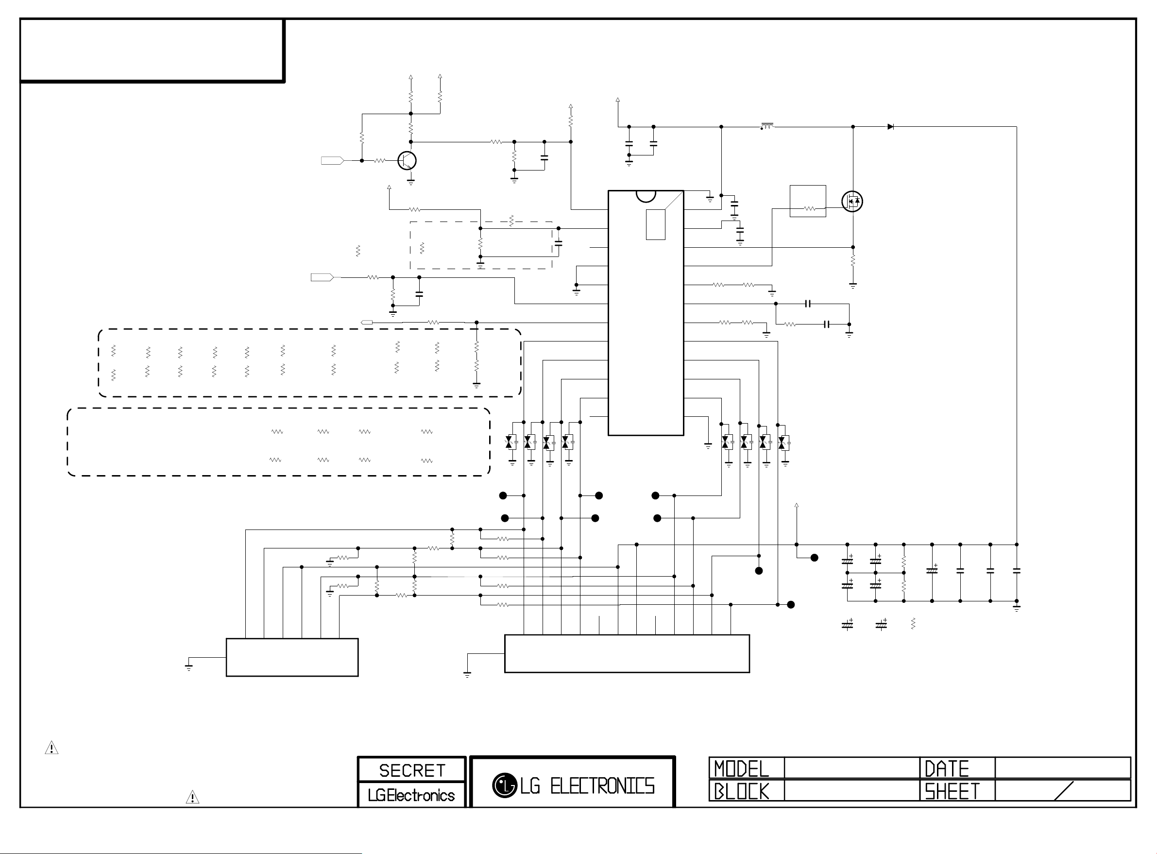
TBD
Copyright ⓒ 2015 LG Electronics. Inc. All right reserved.
Only for training and service purposes
LGE Internal Use Only
44A/45A/450A
19.5_AUO
R611-*10
2.2K
5%
19.5_AUO
R612-*10
33K
1%
28_Heesung
R611-*8
28_Heesung
R612-*8
24_INNOLUX
27K
1%
24_INNOLUX
1K
5%
28_BOE & 22_LGD(HD)
R611-*7
22K
1%
R612-*7
1.6K
1%
R611-*6
18K
1%
R612-*6
1K
5%
28_BOE & 22_LGD(HD)
18.5_AUO
R611-*4
2.7K
1%
18.5_AUO
R612-*4
33K
1%
20.7_BOE(BM)
R611-*13
18K 1%
20.7_BOE(BM)
R612-*13
2.7K 1%
INV_ON
DRIVER_Only 20.7 BOE_BM(OVP)
PWM_DIM
BLU_CURRENT_CTL
1%
39K
1%
22_LGD_BM
47K
22_LGD_BM
2.49K
18.5_CMI/21.5_AUO
R611-*12
1/16W
R612-*12
1/16W
18.5_BOE
R611-*3
1.8K
18.5_BOE
R612-*3
LED_Driver_EN_3.3V
READY
R601
10K
DRIVER
R608
100
R611-*2
2.7K
18.5_CMI/21.5_AUO
R612-*2
36K
20.7_BOE
R611-*11
6.8K
1%
1%
1%
1/16W
20.7_BOE
R612-*11
33K
1%
1/16W
+3.3V_M
R628
0
R602
3K
R603
10K
VOUT
DRIVER_Only 28inch(OVP)
R607-*3
47K 1%
READY
R609
100K
FHD_22_HEESUNG
C
Q601
B
MMBT3904(NXP)
E
DRIVER
R606
560K
1%
READY
C603
50V
100pF
R611-*5
2.4K
FHD_22_HEESUNG
R612-*5
39K
15Y model
22_LGD_P15
R611-*9
6.8K
1/16W
22_LGD_P15
R612-*9
18K
1/16W
R607-*1
24K
1%
READY
R610
100K
1%
1%
+5V_USB
LED_Driver_EN_5V
R629
0
R604
1K
1%
DRIVER_Only 24inch(OVP)
DRIVER_Except 24/28inch(OVP)
FHD_24
R611-*1
0
FHD_24
R612-*1
39K
R607
27K
1%
HD_24/FHD_22
R611
680
HD_24/FHD_22
R612
20K
READY
DRIVER
R605
100K
1%
R607-*2
33K
1%
VA600
READY
DRIVER
VA601
READY
BLU_ON
C601
1000pF
50V
DRIVER
VA602
C602
1000pF
50V
READY
BOOST
R627
0
VA603
OVP
NC_1
PGND_1
PGND_2
PDIM
RISET
LS8
LS7
LS6
LS5
NC_2
EN
+19V
DRIVER
DT1641AS
1
2
3
4
5
6
7
8
9
10
11
12
C606
10uF
25V
DRIVER
IC601
DRIVER
C607
10uF
25V
25
THERMAL
24
23
22
21
20
19
18
17
16
15
14
13
[EP]GND
VIN
VREF
CS
NDRV
RSS
COMP
RT
LS1
LS2
LS3
LS4
LGND
DRIVER
R616
240K
DRIVER
R613
39K
1%
1%
READY
DRIVER
C616
1uF
25V
DRIVER
C614
1uF
25V
DRIVER
R617
10K
DRIVER
R614
1.5K
VA604
READY
DRIVER
L601
33UH
EMI Improve
0-> 3.3ohm(12.12.25)
3.3-> 5.6ohm(12.12.25)
1%
4700pF
DRIVER
R615
1%
1.5K
VA606
VA605
READY
VA607
READY
DRIVER
R620
5.6
DRIVER
C605
50V
1%
R618
DRIVER
DRIVER
C604
0.047uF
25V
0.1
DRIVER
D602
BR210
100V
D
DRIVER
Q602
AOD478
G
S
1%
R632
INNOLUX
0
R633
0
R635 0
NOT_Innolux
R630 0
R631
INNOLUX
0
R634
INNOLUX
0
LED Driver NC Pin.5
R625
0
LED Driver NC Pin.2
R626
0
INNOLUX
NOT_Innolux
1
2
3
4
5
6
7
P602
12507WR-06L
1CH/2CH/4CH_Wafer
THE SYMBOL MARK OF THIS SCHEMETIC DIAGRAM INCORPORATES
SPECIAL FEATURES IMPORTANT FOR PROTECTION FROM X-RADIATION.
FIRE AND ELECTRICAL SHOCK HAZARDS, WHEN SERVICING IF IS
ESSENTIAL THAT ONLY MANUFACTURES SPECIFIED PARTS BE USED FOR
THE CRITICAL COMPONENTS IN THE SYMBOL MARK OF THE SCHEMETIC.
LED DRIVER
JP601
JP602
2CH/4CH
2CH/4CH
R621 0
2CH/4CH
R622 0
R623 0
R624
0
2CH/4CH
13
JP605
JP603
JP604
JP606
JP607
1
2
3
4
5
6
7
8
9
10
11
12
VOUT
JP609
JP608
8CH
P601
05002HR-H12 J05
44A/45A/450A
LED_Driver
NON_MLCC
C609
68uF
35V
NON_MLCC
C600
68uF
35V
MLCC_IN
C609-*1
10uF
100V
NON_MLCC
C610
68uF
35V
NON_MLCC
C608
68uF
35V
MLCC_IN
C610-*1
10uF
100V
NON_MLCC
E637
1M
1/8W
NON_MLCC
R638
1M
1/8W
MLCC_IN
R638-*1
0
1/8W
READY
C615
10uF
100V
C611_MLCC_IN
C611
1uF
100V
MLCC_IN
MLCC_IN
C612
1uF
100V
C613
1uF
100V
2013/08/21
6 8
Page 32
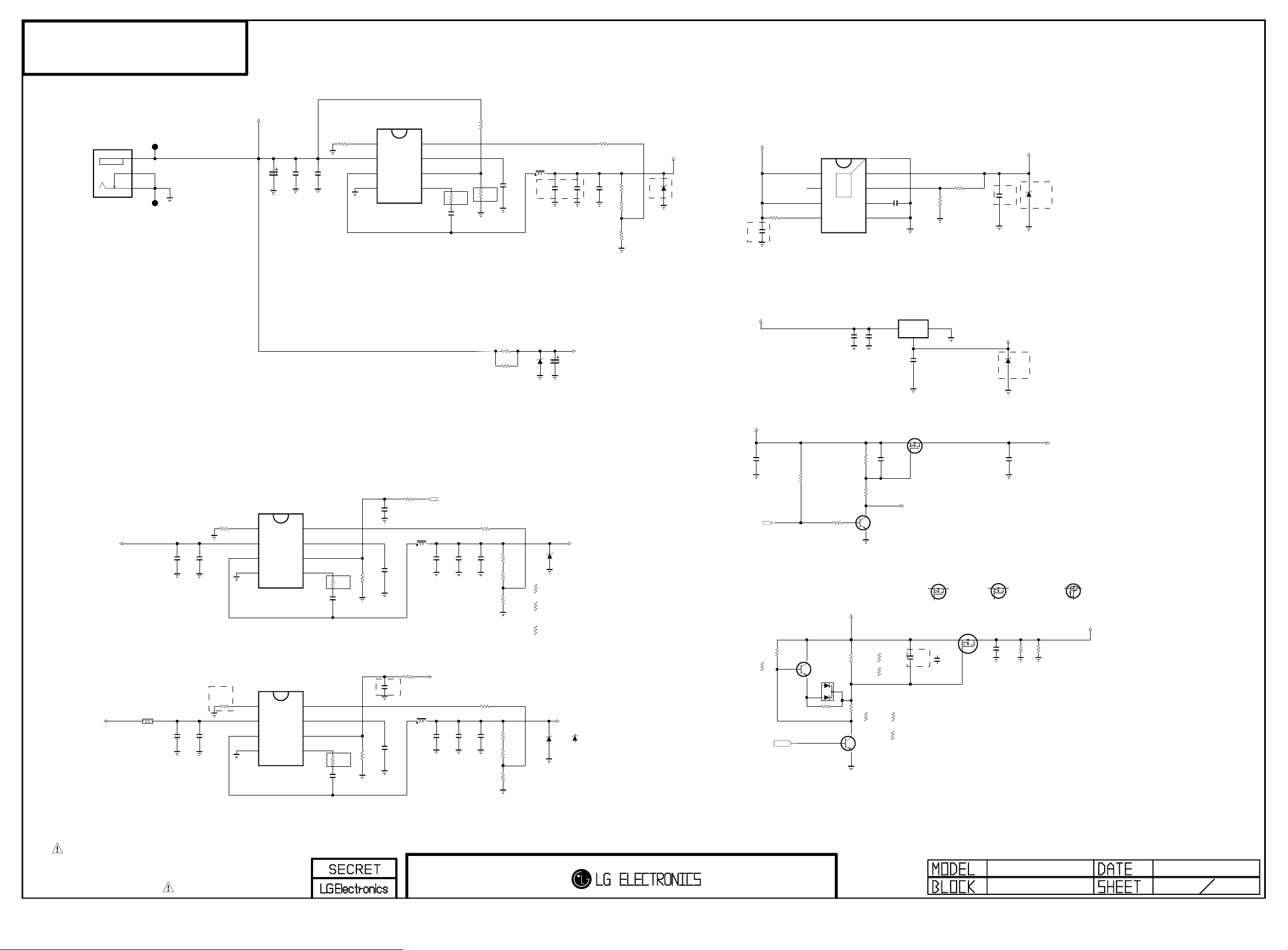
TBD
Copyright ⓒ 2015 LG Electronics. Inc. All right reserved.
Only for training and service purposes
LGE Internal Use Only
44A/45A/450A
19V TO ST3.3V DCDC CONVERTER
KJA-DC-1-0032
+19V
+19V
JK700
JP701
4
4
2
2
1
1
JP702
19V TO PANEL VCC(12V/5V) DCDC CONVERTER
R720
47K
C721
C720
0.1uF
10uF
25V
25V
19V TO USB 5V DCDC CONVERTER
L710
UBW2012-121F
2013.08.09
APPLY -> READY
DCM -> CCM
C770
10uF
25V
C771
0.1uF
25V
READY
R770
47K
+19V
AAM
IN
SW
GND
AAM
IN
SW
GND
IC702
MP2315GJ
1
2
NEW
3
3A
4
IC709
MP2315GJ
1
2
NEW
3
3A
4
C701
68uF
35V
C703
10uF
25V
8
7
6
5
8
7
6
5
FB
VCC
EN/SYNC
BST
FB
VCC
EN/SYNC
BST
R701
47K
C704
0.1uF
25V
20130528 cJ.LIM
R721
68
C722
0.1uF
50V
20130528 cJ.LIM
R772
68
C772
0.1uF
50V
AAM
IN
SW
GND
READY
R722
20K
READY
R773
20K
MP2315GJ
1
2
3
4
20130821
IC701
NEW
3A
READY
C724
0.47uF
16V
C723
0.1uF
25V
C777
1uF
10V
C773
0.1uF
25V
R723
4.7K
R771
20K
8
7
6
5
L720
10uH
L770
10uH
C725
10uF
C774
10uF
FB
VCC
EN/SYNC
BST
POWER_SW
16V
+3.3V_M
10V
20130528 cJ.LIM
R703
68
C705
0.1uF
50V
C727
C726
0.1uF
10uF
25V
16V
C776
C775
0.1uF
10uF
25V
10V
R702
100K
R704
20K
R724
33K
PANEL_12V
R72 5
PANEL_12V
R72 6
100 K
PANEL_12V
R72 7
10K
1%
R774
33K
R77 5
R77 6
R77 7
** 3.5V_ST -> 1.26V VDDC
L702
10uH
C706
0.1uF
25V
X5R(EAE31360401) -> X7R(EAE52158501)
To improve CST Issue.
2013.11.27 by BJ.KIM
C707
10uF
C708
10uF
10V
10V
C709
0.1uF
25V
R705
33K
R70 6
5.1 K
R70 7
R70 8
+3.5V_ST
+3.5V_ST
2013.08.07
5.6B->5V
5V
READY->APPLY
1%
27K
1%
10K
1%
ZD702
R744
10K
C740
10uF
10V
X5R(EAE31360401) -> X7R(EAE52158501)
To improve CST Issue.
2013.11.27 by BJ.KIM
V0 = 0.8*(1+(R2/R1))
AP7173-SPG-13 HF(DIODES)
IC704
IN
1
PG
2
VCC
3
EN
4
9
THERMAL
8
7
6
5
[EP]
OUT
FB
SS
GND
C746
560pF
50V
R1
1%
1%
R740
R741
2.7K
4.7K
X5R(EAE31360401) -> X7R(EAE52158501)
To improve CST Issue.
2013.11.27 by BJ.KIM
C742
10uF
10V
+1.2V_VDDC
OUT:1.26V
ZD703
2.5V
Add for imporving main IC burn Issue.
** 3.3V_M -> 1.8V_M
IC711
+3.3V_M
C743
10uF
R714
470
R715
470
D711
READY
+18V
C714
47uF
18V
25V
X5R(EAE31360401) -> X7R(EAE52158501)
To improve CST Issue.
2013.11.27 by BJ.KIM
10V
** +3.5V_ST -> 3.3V_M
+3.5V_ST
C750
0.1uF
16V
R750
10K
R747
10K
D802
BAT54C
R768
0
B
P_12V
PANEL_12V
R761
39K
PANEL_5V For 20LB450A
C
PANEL_12V
R762
39K
C
B
Q721
MMBT3904(NXP)
E
POWER_SW
P_12V
43K
1%
1%
47K
1%
33K
1%
15K
1%
15V
ZD701
READY
PANEL_5V
R725-*1
47K
1%
PANEL_5V
R726-*1
33K
1%
PANEL_5V
R727-*1
15K
1%
+5V_USB
5.6B
ZD700
+5V_USB_Zener_UDZS5.6B
5.6V
ZD700-*1
+5V_USB_Zener_KDZ5.6V
** Switch Panel-Vcc
PANEL_12V
R767
PANEL_5V
R767-*1
2K
24K
PANEL_ON
B
Q722
C
MMBT3904(NXP)
PANEL_12V
E
A2
A1
PANEL_5V
IN
C744
0.1uF
16V
C753
R748
4.7uF
33K
10V
R749
2.2K
C
Q711
MMBT3904(NXP)
E
PANEL_5V
R761-*1
120K
R761-*2
75K
PANEL_5V
R762-*1
20K
AP1117E18G-13
3
PANEL_5V For 20LB450A
R762-*2
PANEL_5V For 21.5 AUO
ADJ/GND
1
2
OUT
C745
10uF
10V
Q710
AO3435
D
S
G
BOOST_EN
FET Multi_DMP2130L_DIODE
Q720-*1
DMP2130L
D
S
G
FET Multi_AO3407B
Q720
AO3407B
4.7uF_25V_Madrian(Not Used)
C760
4.7uF
25V
C760 X5R(EAE58111501) -> X7R(EAE62772301)
To improve CST Issue.
2013.11.27 by BJ.KIM
12K
R762-*3
18K
C760-*1
4.7uF
4.7uF_16V(Use)
16V
S
+1.8V_M
FET Multi_PMV48XP_NXP
Q720-*2
PMV48XP
D
S
G
D
C761
0.1uF
16V
G
ZD704
5V
Add for imporving main IC burn Issue.
+3.3V_M
C754
10uF
10V
X5R(EAE31360401) -> X7R(EAE52158501)
To improve CST Issue.
2013.11.27 by BJ.KIM
FET Multi_SSM3J332R_TOSHIBA
Q720-*3
SSM3J332R
S
G
PANEL_VCC
READY
R766
R765
4.7K
3.3K
D
THE SYMBOL MARK OF THIS SCHEMETIC DIAGRAM INCORPORATES
SPECIAL FEATURES IMPORTANT FOR PROTECTION FROM X-RADIATION.
FIRE AND ELECTRICAL SHOCK HAZARDS, WHEN SERVICING IF IS
ESSENTIAL THAT ONLY MANUFACTURES SPECIFIED PARTS BE USED FOR
THE CRITICAL COMPONENTS IN THE SYMBOL MARK OF THE SCHEMETIC.
POWER
44A/45A/450A
2013/08/21
7 8POWER
Page 33
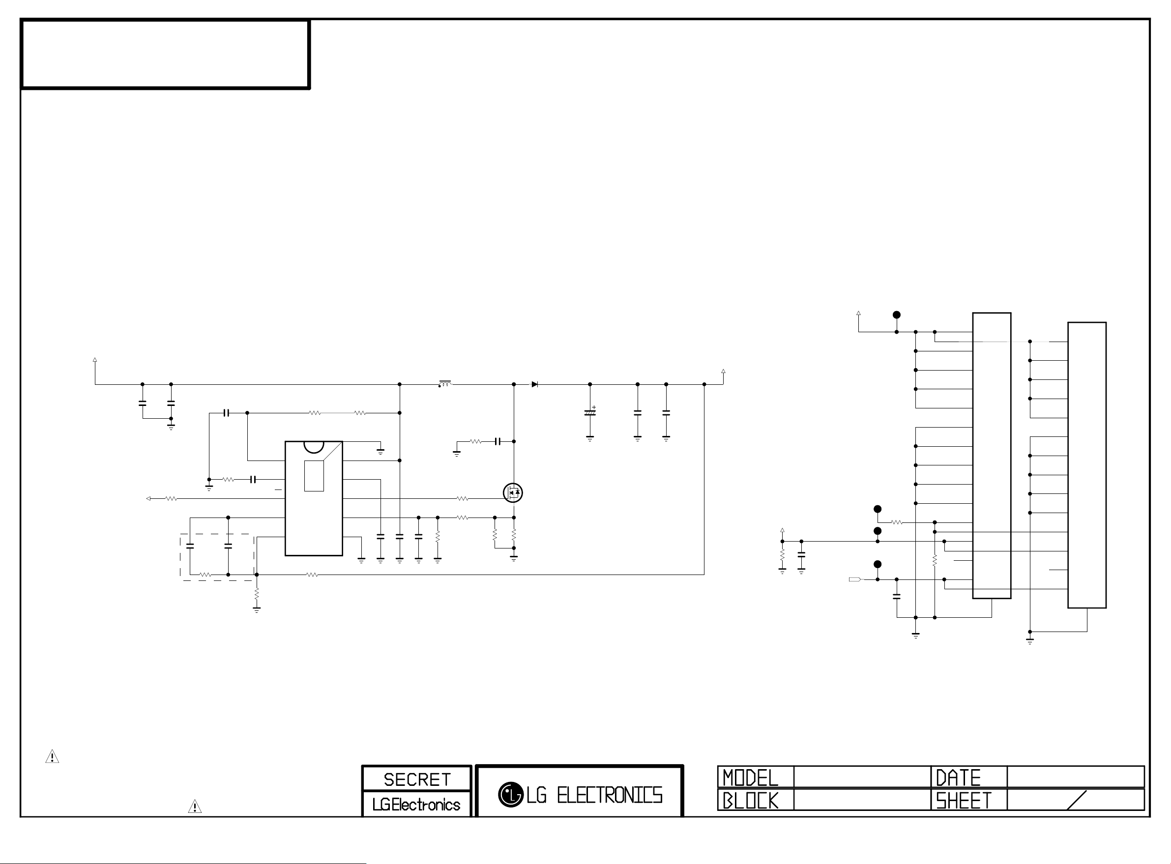
TBD
Copyright ⓒ 2015 LG Electronics. Inc. All right reserved.
Only for training and service purposes
LGE Internal Use Only
44A/45A/450A
+19V
BOOST
C802
10uF
25V
BOOST
R802
BOOST_EN
12.05.17 To improve audible noise
C1103 2200pF->47pF
C1105 47pF->OPT
12.07.03 To improve backlight blinking
C1103 47pF->2200pF
C1105 47pF->Apply
R1103 18K->470K
1K
READY
C803
0.1uF
25V
BOOST
C806
2200pF
50V
BOOST
R805
470K
BOOST
C804
100pF
50V
BOOST
R801
10K
BOOST
C807
47pF
50V
BOOST
R806
1.5K
BOOST
C805
0.22uF
16V
DIS/EN
COMP
TPS40210DGQR
RC
1
SS
2
3
4
FB
5
BOOST
R812
220K
BOOST
IC801
BOOST
R807
51K
11
THERMAL
22/26 HD
P801
24V
24V
24V
24V
24V
GND
GND
GND
GND
GND
ERROR_OUT
INV_ON
READY
PWN_DIM
SM14B-SRSS-TB
1
2
3
4
5
6
7
8
9
10
11
12
NC
13
14
15
GND
+24V_BLU
G
BOOST
R809
0.1
D
S
BOOST
D801
BR210
100V
BOOST
Q801
AOD478
BOOST
C811
68uF
35V
BOOST
C814
1uF
50V
READY
C815
1uF
50V
BOOST
L801
10uH
BOOST
R813
30K
BOOST
C816
BOOST
270pF
R814
[EP]
VDD
10
BP
9
GDRV
8
ISNS
7
GND
6
BOOST
C808
1uF
10V
BOOST
C809
0.1uF
25V
READY
C810
100pF
50V
BOOST
R815
1K
BOOST
R811
5.6
BOOST
R810
1K
50V
10
R808
0.1
READY
+24V_BLU
READY
R822
4.7K
BLU_ON
BOOST
C821
0.1uF
25V
PWM_DIM
JP802
JP803
JP804
READY
C820
1uF
10V
READY
R820
100
JP801
R821
0
27.5 HD(NOT_HEESUNG)
P802
20022WR-14A00
1
2
3
4
5
6
7
8
9
10
11
12
13
14
15
THE SYMBOL MARK OF THIS SCHEMETIC DIAGRAM INCORPORATES
SPECIAL FEATURES IMPORTANT FOR PROTECTION FROM X-RADIATION.
FIRE AND ELECTRICAL SHOCK HAZARDS, WHEN SERVICING IF IS
ESSENTIAL THAT ONLY MANUFACTURES SPECIFIED PARTS BE USED FOR
THE CRITICAL COMPONENTS IN THE SYMBOL MARK OF THE SCHEMETIC.
BOOST-UP
44A/45A/450A
DC BOOST UP
2013/08/21
8 8
Page 34

 Loading...