

LG 20M35D, 24M35D, 24M35A, 22M35A, 22M35D User Manual
...
ENGLISH
OWNER’S MANUAL
LED LCD MONITOR
Please read this manual carefully before operating
your set and retain it for future reference.
LED LCD MONITOR MODEL
19M35A
20M35A
22M35A
24M35A
19M35D
20M35D
22M35D
24M35D
www.lg.com

WARNING: This product contains chemicals known to the State of California to cause cancer and birth defects or other
reproductive harm. Wash hands after handling.

TABLE OF CONTENTS
2
ENGLISH
ENG
CONTENTS
3 ASSEMBLING AND PREPAR-
ING
3 Unpacking
4 Parts and buttons
5 Moving and Lifting the Monitor
6 Setting up the Monitor set
6 - Attaching the Stand Base
6 - Detaching the Stand Base
7 - Mounting on a table
7 - Using the cable holder
9 - Mounting on a wall
10 USING THE MONITOR SET
10 Connecting to a PC
10 - D-SUB connection
10 - DVI-D connection
22 TROUBLESHOOTING
24 SPECIFICATIONS
24 19M35A
25 19M35D
26 20M35A
28 20M35D
30 22M35A
31 22M35D
32 24M35A
33 24M35D
34 Preset Modes (Resolution)
35 Indicator
36 PROPER POSTURE
36 Proper posture for using the Monitor set.
12 CUSTOMIZING SETTINGS
13 Customizing Settings
13 - Menu Settings
14 - Picture
15 - Color
16 - Display
17 - Others
18 READER Setting
19 FUNC. Setting
19 - SUPER ENERGY SAVING
20 - Picture Mode
21 - DUAL DISPLAY
21 - DUAL WEB
ASSEMBLING AND PREPARING
3
ASSEMBLING AND PREPARING
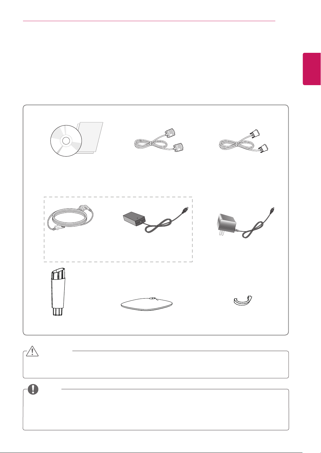
Unpacking
Check your product box for the following items. If there are any missing accessories, contact the local
dealer where you purchased your product. The illustrations in this manual may differ from the actual product
and accessories.
CD(Owner's Manual) /
Card
D-SUB Cable
(This cable is not included in all
(19M35D,20M35D,22M35D,24M35D)
or
DVI-D Cable
countries.)
ENGLISH
ENG
Power Cord
( Depending on the country ) ( Depending on the country )
Stand Body Stand Base
AC-DC Adapter
AC-DC Adapter
Cable holder
CAUTION
Do not use any unapproved accessories to ensure the safety and product life span.
y
Any damages or injuries by using unapproved accessories are not covered by the warranty.
y
NOTE
The accessories supplied with your product may vary depending on the model.
y
Product specifications or contents in this manual may be changed without prior notice due to upgrade
y
of product functions.
ENGLISH
ENG
ASSEMBLING AND PREPARING
4
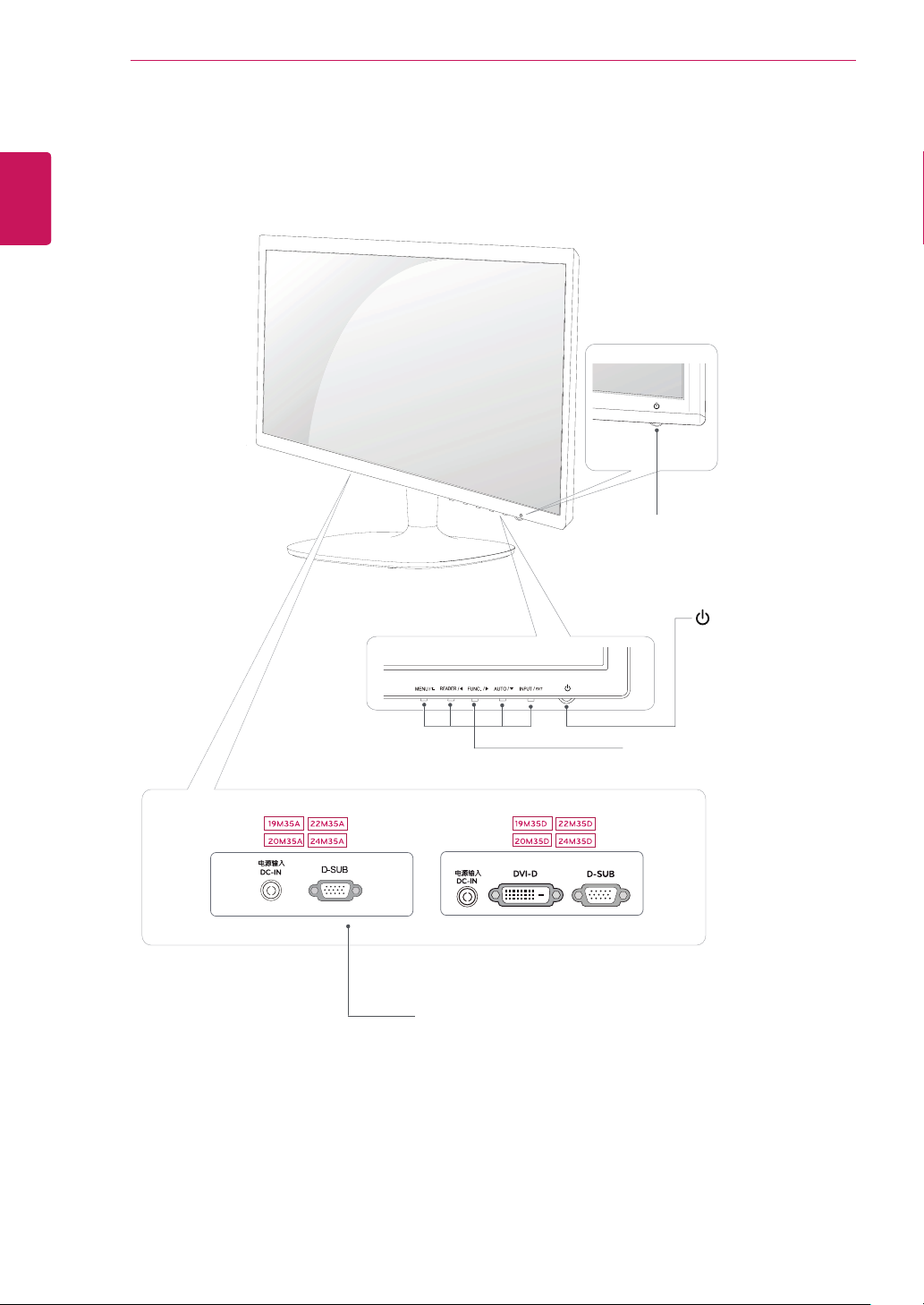
Parts and buttons
Power Indicator
Lighting On: Turned on
y
Lighting Off: Turned off
y
Connection panel (See p.10)
(Power Button)
Button (See p.12)
ASSEMBLING AND PREPARING
5
Moving and Lifting the Monitor
When moving or lifting the monitor, follow these
instructions to prevent the monitor from being
scratched or damaged and to ensure safe transportation regardless of its shape or size.
It is advisable to place the monitor in the
y
original box or packing material before attempting to move it.
Before moving or lifting the monitor, discon-
y
nect the power cord and all cables.
Hold the top and bottom of the monitor frame
y
firmly. Do not hold the panel itself.
When holding the monitor, the screen should
y
face away from you to prevent it being
scratched.
When moving the monitor, avoid any strong
y
shock or vibrations to the product.
When moving the monitor, keep it upright,
y
never turn the monitor on its side or tilt it
sideways.
CAUTION
As far as possible, avoid touching the moni-
y
tor screen. This may result in damage to the
screen or some of the pixels used to create
images.
ENGLISH
ENG
ASSEMBLING AND PREPARING
6
ENGLISH
ENG
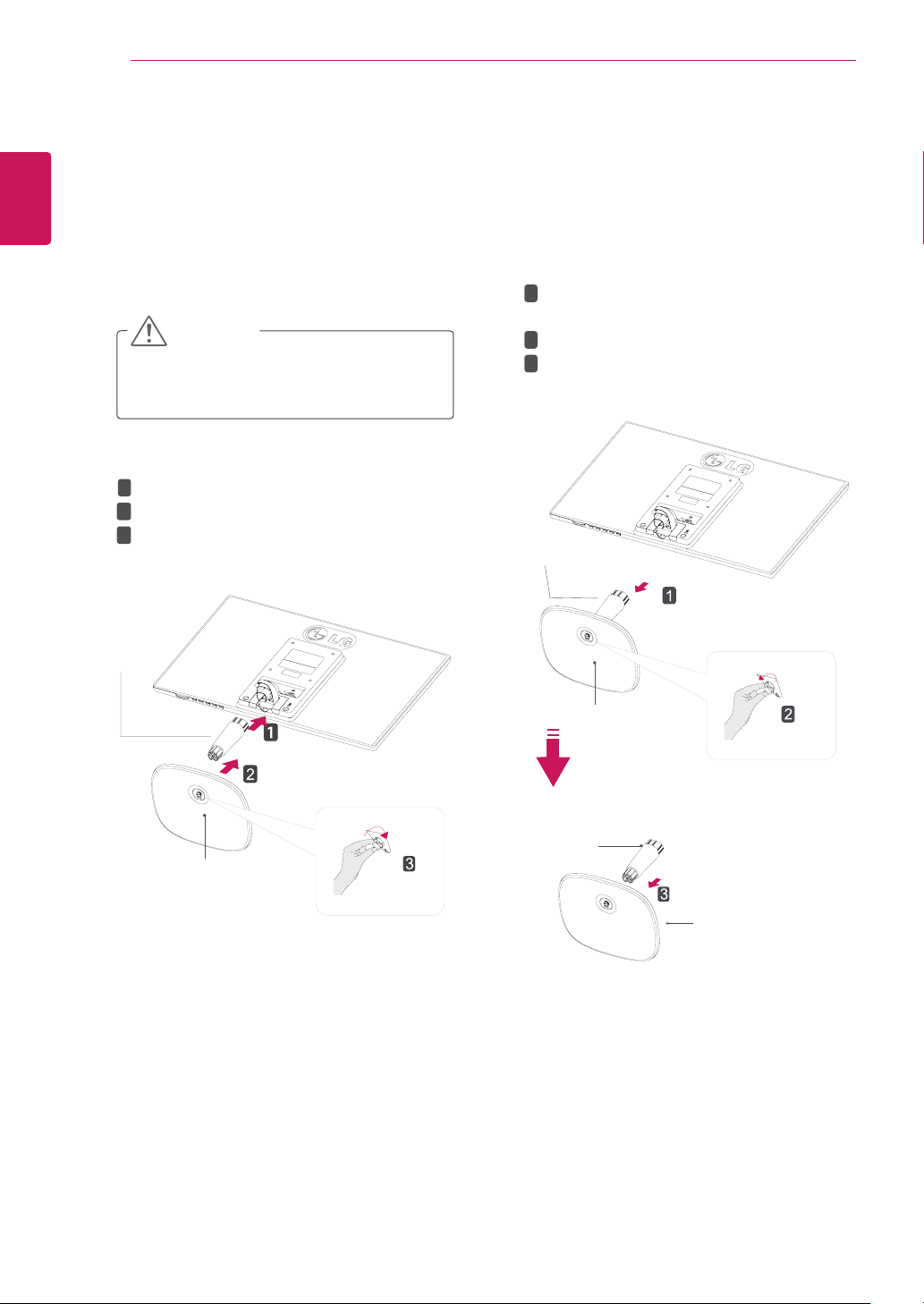
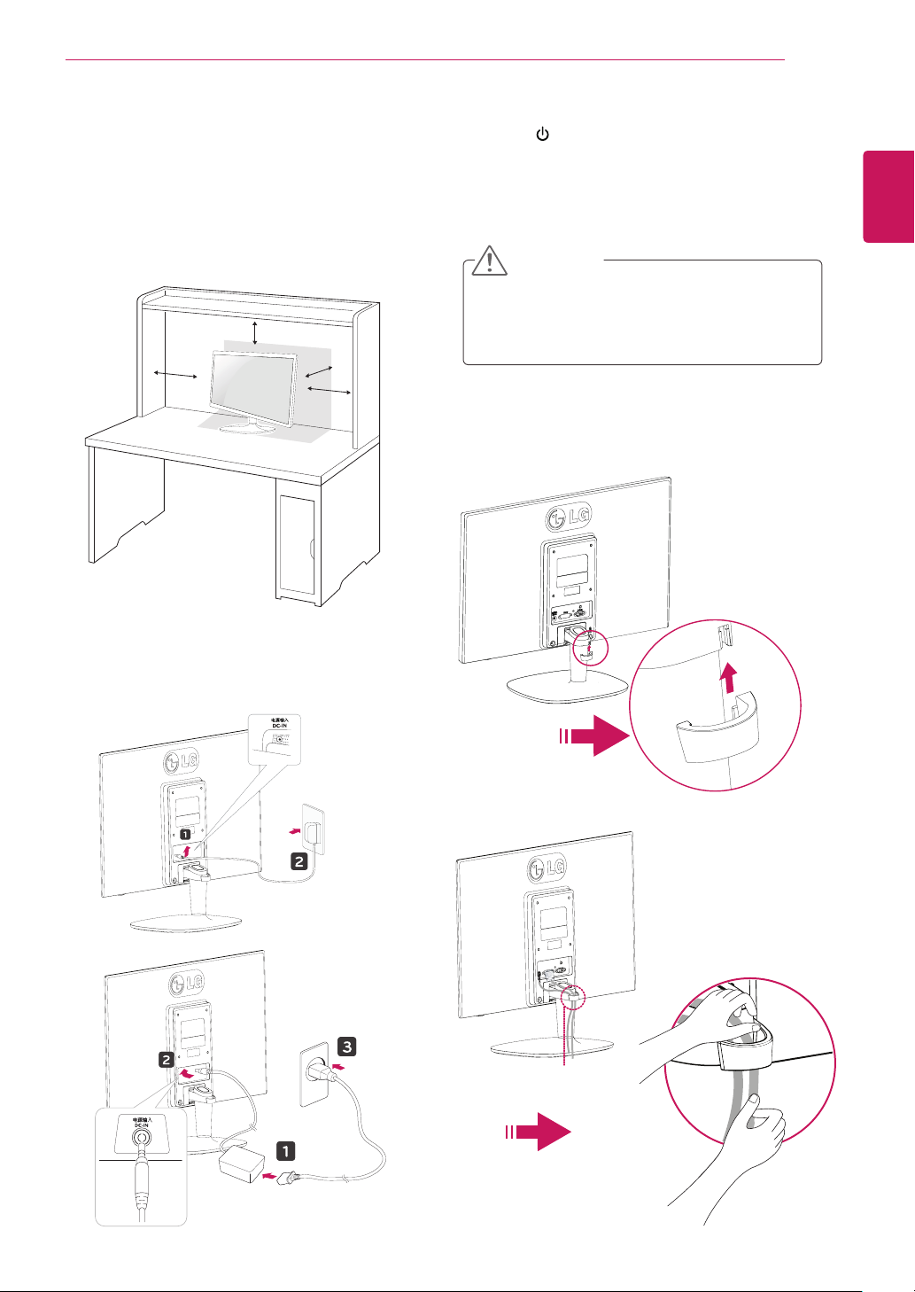
Setting up the Monitor set
Attaching the Stand Base
Place the Monitor set with the screen side
1
down on a flat and cushioned surface.
CAUTION
Lay a foam mat or soft protective cloth
on the surface to protect the screen from
damage.
1
Attach the
2
Attach the
2
Tighten the screw to the right.
3
Stand Body
Stand Base
to the monitor set.
.
Detaching the Stand Base
Place the Monitor set with the screen side
1
down on a flat and cushioned surface.
2
1
Pull out the
from the monitor set.
Turn the screw to the left.
2
Pull out the
3
Stand Body
Stand Body
Stand Base
and
.
Stand Base
Stand Body
Stand Base
Stand Body
Stand Base
Stand Base
ASSEMBLING AND PREPARING
7
Mounting on a table
Lift and tilt the Monitor set into its upright
1
position on a table.
Leave a 10 cm (minimum) space from the wall
for proper ventilation.
10 cm
10 cm
10 cm
10 cm
Press (Power) button on the bottom switch
3
panel to turn the power on.
CAUTION
Unplug the power cord before moving the
Monitor to another location. Otherwise electric
shock may occur.
Using the cable holder
ENGLISH
ENG
Connect the AC-DC Adapter and Power Cord
2
to a wall outlet.
or
Cable holder
ASSEMBLING AND PREPARING
8
ENGLISH
ENG
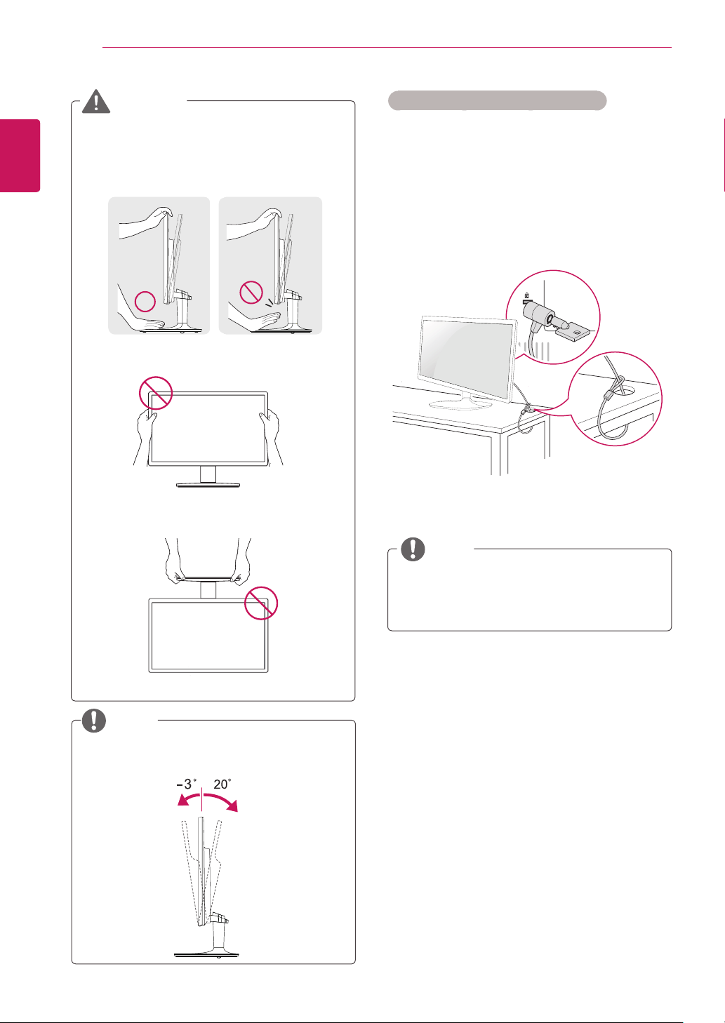
WARNING
When you adjust the angle, do not hold the
bottom of the Monitor set frame as shown on
the following illustration, as may injure your
fingers.
Do not touch or press the screen when
adjusting the angle of the monitor.
Do not hold this set like below picture.Monitor
screen can detach from stand base and injure
your body.
Using the Kensington security system
The Kensington security system connector is
located at the back of the Monitor set. For more
information of installation and using, refer to the
manual supplied with the Kensington security
system or visit
Connect the Kensington security system cable
between the Monitor set and a table.
http://www.kensington.com
.
NOTE
NOTE
Tilt from +20 to -3 degrees up or down to adjust
the angle of the Monitor set to suit your view.
Front Rear
The Kensington security system is optional.
You can obtain it from most electronics stores.
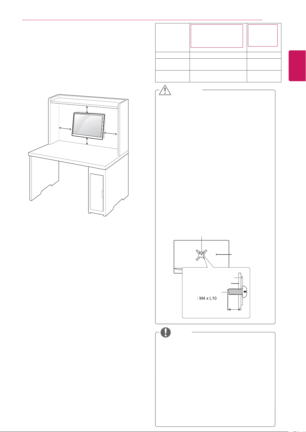
Mounting on a wall
For proper ventilation, allow a clearance of 10 cm
on each side and from the wall. Detailed
instructions are available from your dealer, see the
optional Tilt Wall Mounting Bracket Installation and
Setup Guide.
10 cm
10 cm
If you intend to mount the Monitor set to a wall,
attach Wall mounting interface (optional parts) to
the back of the set.
When you install the Monitor set using a wall
mounting interface (optional parts), attach it
carefully so it will not drop.
Please, Use the screw and wall mount interface
1
in accordance with VESA Standards.
If you use screw longer than standard, the
2
monitor might be damaged internally.
10 cm
10 cm
ASSEMBLING AND PREPARING
Model
VESA (A x B) 75 x 75 100 x 100
Standard
screw
Number of
screws
19M35A 19M35D
20M35A 20M35D
22M35A 22M35D
M4 M4
4 4
24M35A
24M35D
CAUTION
Disconnect the power cord first, and then
y
move or install the Monitor set. Otherwise
electric shock may occur.
If you install the Monitor set on a ceiling or
y
slanted wall, it may fall and result in severe
injury.
Use only an authorized LG wall mount
y
and contact the local dealer or qualified
personnel.
Do not over tighten the screws as this may
y
cause damage to the Monitor set and void
your warranty.
Use only screws and wall mounts that
y
meet the VESA standard. Any damages
or injuries by misuse or using an improper
accessory are not covered by the warranty.
Screw length from outer surface of back
y
cover should be under 8mm.
Wall mount Pad
Back Cover
Wall mount Pad
Back Cover
Standard screw
9
ENGLISH
ENG
If you use improper screw, the product might be
3
damaged and drop from mounted position. In
this case, LG Electronics is not responsible for
it.
VESA compatible only with respect to screw
4
mounting interface dimensions and mounting
screw specifications.
Please use VESA standard as below.
5
784.8 mm (30.9 inch) and under
y
* Wall Mount Pad Thickness : 2.6 mm
* Screw : Φ 4.0 mm x Pitch 0.7 mm x
Length 10 mm
787.4 mm (31.0 inch) and above
y
* Please use VESA standard wall mount pad
and screws.
Max.8mm
NOTE
Use the screws that are listed on the VESA
y
standard screw specifications.
The wall mount kit will include an installation
y
manual and necessary parts.
The wall mount bracket is optional. You can
y
obtain additional accessories from your local
dealer.
The length of screws may differ depending
y
on the wall mount. Be sure to use the proper
length.
For more information, refer to the
y
instructions supplied with the wall mount.
USING THE MONITOR SET
10
ENGLISH
ENG
USING THE MONITOR SET
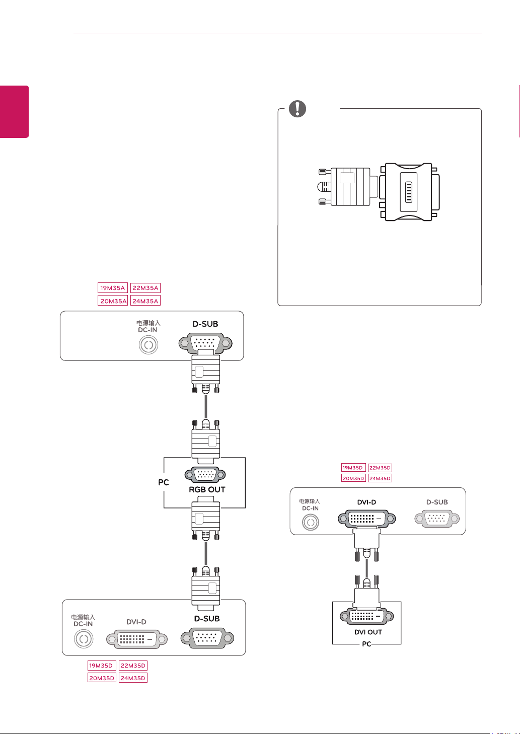
Connecting to a PC
Your Monitor set supports Plug & Play*.
y
*Plug & Play: A PC recognizes a connected
device that users connect to a PC and turn
on, without device configuration or user
intervention.
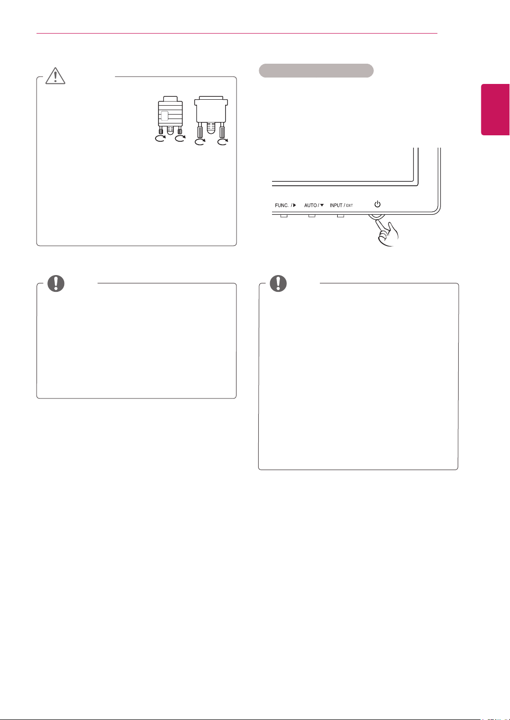
D-SUB connection
Transmits analog video from your PC to the
Monitor set. Connect the PC and the Monitor set
with the supplied D-sub 15 pin signal cable as
shown in the following illustrations.
DVI-D connection
NOTE
When using a D-Sub signal input cable
y
connector for Macintosh
Mac adapter
y
For Apple Macintosh use, a separate plug
adapter is needed to change the 15 pin
high density (3 row) D-SUB VGA connector
on the supplied cable to a 15 pin 2 row
connector.
Transmits a digital video signal from your PC to
the Monitor set. Connect the PC and the Monitor
set with a DVI cable as shown in the following
illustrations.
USING THE MONITOR SET
11
CAUTION
Connect the signal
y
input cable and tighten
it by turning the screws
clockwise.
Do not press the screen with your finger for
y
a long time as this may result in temporary
distortion on the screen.
Avoid displaying a fixed image on the
y
screen for a long period of time to prevent
image burn. Use a screensaver if possible.
Self Image Setting Function
Press the power button on the bottom panel to
turn the power on. When monitor power is turned
on, the "
automatically. (Only supported in Analog Mode)
NOTE NOTE
When you want to use two PC in our Monitor,
y
please connect the signal cable(D-SUB/
DVI-D) respectively in Monitor set.
If you turn the Monitor set on while it is cold,
y
the screen may flicker. This is normal.
Some red, green, or blue spots may appear
y
on the screen. This is normal.
Self Image Setting
"Self Image Setting" Function.
y
This function provides the user with optimal
display settings.When the user connects
the monitor for the first time, this function
automatically adjusts the display to optimal
settings for individual input signals.(Only
supported in Analog Mode)
‘AUTO’ Function.
y
When you encounter problems such as
blurry screen, blurred letters, screen flicker
or tilted screen while using the device or
after changing screen resolution, press the
AUTO function button to improve resolution.
(Only supported in Analog Mode)
" Function is executed
ENGLISH
ENG
 Loading...